EP2974709A1 - Device for spine correction - Google Patents
Device for spine correction Download PDFInfo
- Publication number
- EP2974709A1 EP2974709A1 EP15460003.5A EP15460003A EP2974709A1 EP 2974709 A1 EP2974709 A1 EP 2974709A1 EP 15460003 A EP15460003 A EP 15460003A EP 2974709 A1 EP2974709 A1 EP 2974709A1
- Authority
- EP
- European Patent Office
- Prior art keywords
- spine
- elements
- frame
- support
- segments
- Prior art date
- Legal status (The legal status is an assumption and is not a legal conclusion. Google has not performed a legal analysis and makes no representation as to the accuracy of the status listed.)
- Granted
Links
Images




Classifications
-
- A—HUMAN NECESSITIES
- A61—MEDICAL OR VETERINARY SCIENCE; HYGIENE
- A61H—PHYSICAL THERAPY APPARATUS, e.g. DEVICES FOR LOCATING OR STIMULATING REFLEX POINTS IN THE BODY; ARTIFICIAL RESPIRATION; MASSAGE; BATHING DEVICES FOR SPECIAL THERAPEUTIC OR HYGIENIC PURPOSES OR SPECIFIC PARTS OF THE BODY
- A61H1/00—Apparatus for passive exercising; Vibrating apparatus; Chiropractic devices, e.g. body impacting devices, external devices for briefly extending or aligning unbroken bones
- A61H1/001—Apparatus for applying movements to the whole body
- A61H1/003—Rocking or oscillating around a horizontal axis transverse to the body
-
- A—HUMAN NECESSITIES
- A61—MEDICAL OR VETERINARY SCIENCE; HYGIENE
- A61H—PHYSICAL THERAPY APPARATUS, e.g. DEVICES FOR LOCATING OR STIMULATING REFLEX POINTS IN THE BODY; ARTIFICIAL RESPIRATION; MASSAGE; BATHING DEVICES FOR SPECIAL THERAPEUTIC OR HYGIENIC PURPOSES OR SPECIFIC PARTS OF THE BODY
- A61H1/00—Apparatus for passive exercising; Vibrating apparatus; Chiropractic devices, e.g. body impacting devices, external devices for briefly extending or aligning unbroken bones
- A61H1/008—Apparatus for applying pressure or blows almost perpendicular to the body or limb axis, e.g. chiropractic devices for repositioning vertebrae, correcting deformation
-
- A—HUMAN NECESSITIES
- A61—MEDICAL OR VETERINARY SCIENCE; HYGIENE
- A61H—PHYSICAL THERAPY APPARATUS, e.g. DEVICES FOR LOCATING OR STIMULATING REFLEX POINTS IN THE BODY; ARTIFICIAL RESPIRATION; MASSAGE; BATHING DEVICES FOR SPECIAL THERAPEUTIC OR HYGIENIC PURPOSES OR SPECIFIC PARTS OF THE BODY
- A61H2201/00—Characteristics of apparatus not provided for in the preceding codes
- A61H2201/16—Physical interface with patient
- A61H2201/1602—Physical interface with patient kind of interface, e.g. head rest, knee support or lumbar support
- A61H2201/1623—Back
-
- A—HUMAN NECESSITIES
- A61—MEDICAL OR VETERINARY SCIENCE; HYGIENE
- A61H—PHYSICAL THERAPY APPARATUS, e.g. DEVICES FOR LOCATING OR STIMULATING REFLEX POINTS IN THE BODY; ARTIFICIAL RESPIRATION; MASSAGE; BATHING DEVICES FOR SPECIAL THERAPEUTIC OR HYGIENIC PURPOSES OR SPECIFIC PARTS OF THE BODY
- A61H2201/00—Characteristics of apparatus not provided for in the preceding codes
- A61H2201/16—Physical interface with patient
- A61H2201/1657—Movement of interface, i.e. force application means
- A61H2201/1676—Pivoting
-
- A—HUMAN NECESSITIES
- A61—MEDICAL OR VETERINARY SCIENCE; HYGIENE
- A61H—PHYSICAL THERAPY APPARATUS, e.g. DEVICES FOR LOCATING OR STIMULATING REFLEX POINTS IN THE BODY; ARTIFICIAL RESPIRATION; MASSAGE; BATHING DEVICES FOR SPECIAL THERAPEUTIC OR HYGIENIC PURPOSES OR SPECIFIC PARTS OF THE BODY
- A61H2201/00—Characteristics of apparatus not provided for in the preceding codes
- A61H2201/50—Control means thereof
- A61H2201/5007—Control means thereof computer controlled
-
- A—HUMAN NECESSITIES
- A61—MEDICAL OR VETERINARY SCIENCE; HYGIENE
- A61H—PHYSICAL THERAPY APPARATUS, e.g. DEVICES FOR LOCATING OR STIMULATING REFLEX POINTS IN THE BODY; ARTIFICIAL RESPIRATION; MASSAGE; BATHING DEVICES FOR SPECIAL THERAPEUTIC OR HYGIENIC PURPOSES OR SPECIFIC PARTS OF THE BODY
- A61H2201/00—Characteristics of apparatus not provided for in the preceding codes
- A61H2201/50—Control means thereof
- A61H2201/5058—Sensors or detectors
- A61H2201/5061—Force sensors
-
- A—HUMAN NECESSITIES
- A61—MEDICAL OR VETERINARY SCIENCE; HYGIENE
- A61H—PHYSICAL THERAPY APPARATUS, e.g. DEVICES FOR LOCATING OR STIMULATING REFLEX POINTS IN THE BODY; ARTIFICIAL RESPIRATION; MASSAGE; BATHING DEVICES FOR SPECIAL THERAPEUTIC OR HYGIENIC PURPOSES OR SPECIFIC PARTS OF THE BODY
- A61H2201/00—Characteristics of apparatus not provided for in the preceding codes
- A61H2201/50—Control means thereof
- A61H2201/5058—Sensors or detectors
- A61H2201/5069—Angle sensors
-
- A—HUMAN NECESSITIES
- A61—MEDICAL OR VETERINARY SCIENCE; HYGIENE
- A61H—PHYSICAL THERAPY APPARATUS, e.g. DEVICES FOR LOCATING OR STIMULATING REFLEX POINTS IN THE BODY; ARTIFICIAL RESPIRATION; MASSAGE; BATHING DEVICES FOR SPECIAL THERAPEUTIC OR HYGIENIC PURPOSES OR SPECIFIC PARTS OF THE BODY
- A61H2203/00—Additional characteristics concerning the patient
- A61H2203/04—Position of the patient
- A61H2203/0443—Position of the patient substantially horizontal
- A61H2203/045—Position of the patient substantially horizontal with legs in a kneeled 90°/90°-position
-
- A—HUMAN NECESSITIES
- A61—MEDICAL OR VETERINARY SCIENCE; HYGIENE
- A61H—PHYSICAL THERAPY APPARATUS, e.g. DEVICES FOR LOCATING OR STIMULATING REFLEX POINTS IN THE BODY; ARTIFICIAL RESPIRATION; MASSAGE; BATHING DEVICES FOR SPECIAL THERAPEUTIC OR HYGIENIC PURPOSES OR SPECIFIC PARTS OF THE BODY
- A61H2203/00—Additional characteristics concerning the patient
- A61H2203/04—Position of the patient
- A61H2203/0443—Position of the patient substantially horizontal
- A61H2203/0456—Supine
-
- A—HUMAN NECESSITIES
- A61—MEDICAL OR VETERINARY SCIENCE; HYGIENE
- A61H—PHYSICAL THERAPY APPARATUS, e.g. DEVICES FOR LOCATING OR STIMULATING REFLEX POINTS IN THE BODY; ARTIFICIAL RESPIRATION; MASSAGE; BATHING DEVICES FOR SPECIAL THERAPEUTIC OR HYGIENIC PURPOSES OR SPECIFIC PARTS OF THE BODY
- A61H2205/00—Devices for specific parts of the body
- A61H2205/08—Trunk
- A61H2205/081—Back
Definitions
- the subject matter of this invention is a device for correction of the spine, used for dynamic correction of the spine, in particular in humans, which results in restored physiological joint mobility in the blocked joints of the spine.
- the invention is a member of a group of physiotherapeutic gymnastic-correction devices and is intended to support physiotherapy of the spine. It is used mostly by specialists providing medical physiotherapy services, such as physicians, persons holding master's degrees in movement rehabilitation, physiotherapists and, in particular, specialists in manual medicine, namely chiropractors.
- the subject matter of the invention is also a measurement system that enables recording the progress of the patient.
- Patent application no. US6132004A describes a system of pillows that support the spine in the sitting position, which is intended for persons suffering from pain of the spine.
- Patent application no. EP0712286B1 describes an adjustable support of a seat with a profile that matches the curvature of the spine of the sitting person.
- Patent application no. WO2013088182A1 describes a device for treatment and rehabilitation of patients with spinal pain.
- the device comprises a frame, divided into two parts, which enables performance of procedures in the sitting position and with the patient lying face down.
- the principle of operation of the device is based on appropriate stretching (pulling) of the vertebrae of the patient's spine, in the sitting position with traction devices fixed to the patient's arms, and in the case of the lying position by means of traction devices fixed to the patient's ankles.
- the use of drive devices enables the performance of dynamic procedures.
- Patent application no. WO2013087009A1 describes a system for changing the line of vertebrae as a result of stretching.
- the patient is placed on a bed or table of the device, on a supporting element located on the level of the lumbar lordosis. Stretching with an appropriate force and at an appropriate angle affects the vertebrae of the spine.
- Document PL 215141 B1 presents an orthopaedic curvature corrector, especially the human body, intended for correcting bad posture.
- the device comprises arched cams with a curved arch surface, curvilinear surface or components in the form of a convex upper support in the case of a neck lordosis, concave central support in the case of breast kyphosis and a convex lower support in the case of lumbar lordosis, which form a surface or elements of supports in the form of convex, concave or ellipsoidal cams with curvilinear shapes and curved arch surfaces of arched shapes, which are tangent to the back and, thanks to their shape, are automatically shortened or extended depending on the size, shape and structure of the elements that support the patient, on the shape of the spine or on the shape on the back.
- the arches of those elements represent, in a negative and inertia-based manner, the correct bends of the spine as a result of pressure tangential to the supported elements, namely the back.
- the elements mutually interact with each other - by moving in a complex rolling and sliding motion, thanks to the fixing connections in the guiding holes and correct proper bends of the spine.
- Patent description no. PL 215142 B1 discloses a device for dynamic correction of the spine, in particular the human body, during which physiological joint mobility is restored in blocked joints of the spine.
- the actuators which are set tangentially in the vicinity of the bases of the spinous processes in the individual segments of the spine.
- the actuators correct the spine by restoring joint mobility in the blocked joints of the spine, in particular the human body, during dynamic rotational movement of the relieved spine.
- Rotational movement of the spine is achieved thanks to the action of the entire kinematic chain, which is the movement of alternately moving upper and lower limbs.
- the starting position for movement in this device is the position of the spine described as neutral, i.e. intermediate position between a bent position and a straight position. In this position, the joint surfaces are under the lowest load in the so-called movement part, and the stabilising system, namely the muscles, the ligaments and the joint capsule, are under the least tension.
- the purpose of the invention is a device that ensures dynamic correction that restores precise and accurate physiological joint mobility in blocked spine joints. Thanks to the device according to the invention, a specific stabilisation and correction of the spine is achieved, in the traction position, which enables simultaneous muscular training, while restoring the mobility of spine joints in a very broadly defined therapy of the spine in men.
- the device according to the invention is designed so that it can be used to conduct very thorough muscular training, enabling performance of rotational movements of individual elements of the spine, which are both corrective movements and movements that mobilise the joints of the spine.
- the device according to the invention enables achieving spine rotation movement in the corrected position by way of alternating movements of the upper and lower limbs and by way of alternating use of an external force for this purpose, namely a passive movement drive - the movement drive of the torsional axis, thus resulting in passive movement or another predefined movement.
- the purpose of the invention is to develop a device for rehabilitation of all sections of the spine, which, using rotational exercises performed by the patient, increases the range of movement of the vertebrae of the spine, improves movement coordination, corrects bad posture and positively influences physical fitness and the general well-being of the patient.
- the distinguishing feature of this solution is its universality, the broad group of interested patients who can use the device, with regard to both the patient's size and his or her disease, and the possibility to adjust movement resistance according to the patient's fitness level and to safety.
- the purpose of the invention is the possibility to record, using a measurement system, the progress and the changes in different patients as a result of the rehabilitation performed using the device according to the invention. This increases safety and ensures control over the rehabilitation process.
- the device for spine correction is characterised by the fact that it comprises at least one keyboard, with at least one set of cooperating segments A, B and C supported on curved arch elements, whereby the framework comprises a support frame and a mobile frame on which the keyboard is located.
- segments A, B and C each have a support part and two ribs, whereby the longer arms of the support part of segment A are narrower than the longer arms of the support parts of segment B and segment C; also, the lower brackets of the elastic elements of segment B are rotated 180 degrees in relation to the lower brackets of the elastic elements of segment C.
- the rib has a separate base that is swivel connected, through a kinematic couple, with a back support on the side of the patient rolling axis and additionally through a spring assembly, whereby the back support on the side of the patient rolling axis ends with a pushing device, and on the bottom of the base of the rib, there is a curvature.
- segments A, B and C cooperate with each other through flexible elastic elements.
- the support part comprises adjusting calibrating elements in the form of at least two guide grooves located symmetrically in the lower support part; additionally, preferably in the guide groove, there is at least one curved arch element, on which at least one curvature of the rib is supported.
- the factor that corrects the curvature of the back is constituted by curved arch elements with predefined, finite shapes.
- the device has a set of curved arch elements located symmetrically along the plane passing through the patient rolling axis.
- At the base of the support part there are sensors for measuring the rotation angle of the individual segments of the spine.
- the support part on the external ends of the opposite longer arms has shaped cut-outs, in which the zeroing rod is located.
- each thigh frame connected, through a kinematic couple, to the shin frame ending in a stirrup; wherein, the thigh frame is connected to the shin frame with a resistance assembly that comprises elastic elements that comprise a pulling gas spring and a hydraulic choke, whereby on the inner side of the thigh frame, a profiled support is located.
- the mobile frame ends at the top in two symmetrical resistance mechanisms for the upper limbs, whose shared part is a mounting base connected, through a kinematic couple, to at least one arm, connected through a kinematic couple to the forearm, ending with an end assembly; also, the arm and the forearm are connected to the main resistance assembly, which comprises elastic elements comprising a pulling gas spring and a hydraulic choke, and on the outside, they are surrounded with a parallelogram mechanism, namely a connection of the articulated joint node with the spreader of the arm and the spreader of the forearm; wherein, the arm is connected to the mounting base with the auxiliary resistance assembly.
- the main resistance assembly which comprises elastic elements comprising a pulling gas spring and a hydraulic choke
- the measurement system is characterised by the fact that the controller is connected to a set of sensors of segments A, B and C of the device for spine correction and with a server connected to a screen.
- the server and the screen constitute a PC monoblock which is connected to the controller.
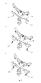
- fig. 1a shows a schematic view of the side of the device for spine correction, in the sitting position
- fig. 1b shows a schematic view of the side of the device for spine correction, in the lying position
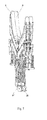
- fig. 2 shows the schematic view of a single segment of the keyboard
- fig. 3 shows the schematic view of the side of a single rib of a keyboard segment
- fig. 4 shows the schematic view of the front of a single keyboard segment with the segment ribs extended the furthest
- fig. 5 shows the schematic view of a part of the keyboard with the rolling axis marked
- fig. 6 shows the schematic exploded view of segments A, B and C, fig.
- FIG. 7 shows the schematic view of a side of a part of the keyboard of the device for spine correction
- fig. 8 shows the schematic view of the side of the keyboard with marked curved arch elements A, B and C
- fig. 9 shows the schematic view of the keyboard with the zeroing mechanism marked
- fig. 10 shows the schematic view of the right resistance mechanism for the lower limbs
- fig. 11 shows the schematic view of the resistance mechanism for the upper limbs
- fig. 12 shows the schematic view of the end assembly of the resistance mechanism for the upper limbs
- fig. 13 shows the functional diagram of the system.
- the device for spine correction has a fixed arm 1 that is 1,600 mm long and 560 mm high, at the highest point, i.e. in the part where the mobile frame 2 is mounted, and 1,100 mm wide.
- the mobile frame 2 is fixed in a movable manner on the fixed frame 1, which is 1,450 mm high, 1,050 mm wide and 800 mm deep.
- a Glisson loop 8 is mounted, and the distance measured from the base of the frame 2 to the end of the Glisson loop 8 is equal to 1,800 mm.
- This starting position guarantees that the patient starts the procedure in a safe foetal position.
- the drive of the torsional axis 11 is mounted, which acts as an element that supports rehabilitation.
- a lock of the side belt 9 is located, which, together with the Glisson loop 8, ensures safety and stabilisation of the patient.
- a keyboard 3 is also located, which is 750 mm long and comprises 37 segments.
- each segment consists of a support part 13 and two identical ribs 12.
- the support part 13 is a welded structure consisting of sheet metal parts, such as brackets and separators, and of spreading elements.
- the support part 13 cooperates with the beam of the mobile frame 2 though a slide bearing set in the main sleeve.
- the axis of the beam is the patient rolling axis 48, namely the rotation axis, with simultaneous extension with the correction of the spine's curves maintained in the neutral positions.
- brackets 45, 46A and 46B of the elastic elements that position and secure the elastic elements 44, which connect the neighbouring segments A, B and C of keyboard 3.
- the elastic elements 44 that are used are fixed symmetrically between segments A, B and C, on both sides of each segment.
- This solution enables even distribution of the torsional moment on the individual segments of the keyboard 3, thus enabling even working of the spine along its entire length, while preserving its anatomic bends.
- the maximum total angle of torsion of the keyboard 3 between the first and the last segment is up to 90 degrees. Consequently, two neighbouring segments must be able to turn in relation to each other by about 2.5 degrees in both directions.
- This solution secures and enables use of the maximum mobility of successive segments of the patient's spine in relation to each other and of a predefined movement.
- each support part 13 comprises adjusting calibrating elements in the form of two guide grooves 19 located symmetrically in the lower section of the support part 13.
- the keyboard 3, through the set of support parts 13, represents the variable geometry of the surface of the human back, thus constituting mobile dynamic support for the human back.
- Each rib 12 of the segment comprises a separate base 14, which is swivel-connected on the side of the patient rolling axis 48 through a kinetic couple of the 5th class with the back support 15.
- the kinematic couple of the 5th class can be a roller articulation, such as a slide bearing.
- a rib 12 with the base 14 of the rib is connected on the external end through the spring assembly 16.
- the back support 15, on the side of the patient rolling axis 48 ends with a pushing device 17, which, by pressing the space in the vicinity of the perivertebral muscles, massages those muscles, i.e. presses and rubs them, thus fixing the geometry of the spine.
- the base 14 of the rib 12 In the lower part of the base 14 of the rib 12, there is the curvature 18, on which the base 14 of the rib 12 is supported on the curved arch elements 10 located in the guide grooves 19 of the support parts 13.
- the base 14 of the rib 12 shapes the bends of the spine and forces the patient to achieve proper curves.
- the back support 15 adjusts to the back by pressing, thus achieving a negative image of the back.
- curved arch elements 10 shown in fig. 8 , which are elements of predefined strictly defined shapes. They are distributed into two sets with three curved arch elements each (10A, 10B and 10C), as shown in fig. 1a and fig. 8 . Each set consists of two smaller curved arch elements 10A and 10C located on the opposite ends of the larger curved arch element 10C.
- the curved arch elements 10A and 10C are convex on both sides and are used for proper lordotization of the cervical and the lumbar sections of the spine, while the central curved arch element 10B, which is concave on one side, is much longer and ensures correction of the shape of the thoracic kyphosis.
- the support part 13 on the external ends of the opposite longer arms has shaped cut-outs 47 in which the zeroing rod 25 is located.
- the zeroing mechanism 5 of the keyboard 3 is used for forcing relative movement of successive neighbouring segments of the keyboard 3 in order to locate the base of the segment sensor.
- the zeroing mechanism 5 constitutes the modular part fixed to the mobile frame 2.
- Zeroing of the keyboard 3 is performed by placing the zeroing rod 25 between the interlocking shaped cut-outs 47 in the support parts 13 of the segments of the keyboard 3.
- the shaped cut-outs 47 are selected so that in the final phase, they enable permanent blocking of the keyboard 3, and, after the zeroing rod 25 is moved back, the keyboard 3 returns to the zero position thanks to its own elastic elements 44. Due to the large number of segments, at the first stage of zeroing, the zeroing rod 25 is pressed to the segments on one side only. By pressing on the other side, the successive segments of the keyboard 3 are then gradually forced to move.
- the resistance mechanisms 4 and 6 for the upper limbs and the lower limbs are fixed to the mobile frame 2.
- the resistance mechanisms 4 and 6 are modular structures and are independent of the structure of the mobile frame 2. Consequently, replacement or modification of the resistance mechanisms 4 and 6 does not require changes to the structure of the mobile frame 2.
- Each resistance mechanism 4 for the lower limbs comprises the thigh frame 29 connected, through a kinematic couple of the 5th class, to the shin frame 30 and ended with a stirrup.
- the stirrup consists of a foot support 31, a proper support and a foot lock.
- the shin frame 30 constitutes a guide for the foot support 31, forming with it a progressive couple; also, the shin frame 30 has a device to block the position of the foot support 31, in the form of a compression lever.
- a force measurement sensor mechanism is located in the structure of the stirrup or, more exactly, in the structure of the proper support.
- the thigh frame 29 with the shin frame 30 additionally provides connection to the resistance assembly 32, which is spread between the fixed lock 28 and the shin frame 30.
- the resistance assembly 32 comprises active resistance elements and passive resistance elements.
- An active resistance element is the gas spring, which ensures the initial resistance force and brings the mechanism to the starting position during rest. Operation of the active resistance elements ensures that the resistance assembly 32 is brought to the fixed position, where the thigh frame 29 and the shin frame 30 are in constant orientation in relation to the lock 28.
- a passive resistance element is the hydraulic choke of regulated chocking action, which is used for adjusting the resistance force in the pushing direction.
- the lock 28 is used for controlling the initial configuration of resistance of the lower limbs.
- a change in the orientation of the lock 28 in relation to the mobile frame 2 results in a change in the initial, forced position of the lower limbs, from the sitting position to the curled-up position.
- the profiled support 33 is located on the inner side of the thigh frame 29, the profiled support 33 is located.
- the purpose of both thigh frames 29, the left one and the right one, is to approximately replicate the movement of the patient's thighs, thus constituting additional support for them in the rest position by using the profiled foot supports 31.
- the two upper limb resistance mechanisms 6 (ULRM), installed symmetrically in the upper part of the mobile frame 2, are intended to provide a load on the upper limbs during the performance of exercises in the horizontal position.
- the shared part of both resistance mechanisms 6 is the mounting base 34, which is a welded structure with assembly elements, connected through a kinematic couple to the arm 36.
- the kinematic couple is a rotating couple of the 5th class, namely a rotating articulated joint with a single degree of freedom.
- the arm 36 is further connected, through the kinematic couple of the 5th class, to the forearm 38 ending, respectively, to the left and right end assembly 40 and 41.
- the arm 36 and the forearm 38 are welded structures consisting of steel profiles and assembly elements.
- the distance between the left kinematic couple, which connects the arm 36 to the forearm 38, and the right kinematic couple, in the folded position is equal to 1,220 mm, and in the furthest open position -to 1,630 mm
- the arm 36 and the forearm 38 are connected to the main resistance assembly 42, which comprises elastic elements.
- the main resistance assembly 42 ensures regulated resistance force acting against the upper limbs during the performance of exercise.
- the elastic elements that are used are active resistance elements and passive resistance elements.
- An active resistance element is the pulling gas spring, which ensures the initial resistance force and brings the mechanism to the starting position.
- the passive resistance elements are used to adjust the resistance force in the pushing direction; an example is the hydraulic choke with regulation of appropriate choking.
- the arm 36 is connected to the mounting base 34 with the auxiliary resistance assembly 43 in the form of a pushing gas spring.
- the auxiliary resistance assembly 43 ensures return of the mechanism to the initial configuration, i.e. the position with the arms open, and secures the limb mechanism against a free, uncontrolled drop of the mobile frame 2 to the horizontal position.
- the arm 36 and the forearm 38 are surrounded on the outside by the parallelogram mechanism, i.e. a connection between the articulated joint node 35 to the spreader of the arm 37 and the spreader of the forearm 39.
- the two symmetrical parallelogram mechanisms ensure constant orientation of the ends 40 and 41 together with the handle 22 in relation to the mounting base 34.
- the assemblies of the ends 40 and 41 are welded structures, which constitute the framework for the adjustable handle 22.
- the distance between the left end assembly 40 and the right end assembly 41 in the folded position is equal to 300 mm, and in the most opened position - 720 mm.
- the handle 22 is adjusted by releasing the positioning pin, i.e. the position lock 23. Protection against dropping and constant orientation of the handle 22 in relation to the end 20 is provided by the blocking pin, i.e. the drop lock 24.
- the handle 22 is fixed to the welded end 20 through the handle mount 21, which enables adjustment of its height.
- the handle 22 has an additional articulated joint, which enables setting its orientation in relation to the end 20.
- Another embodiment of the device for spine correction is a wheelchair with adjustable back support and a lying rest position, for ill persons and for mobile observing of ill persons by medical staff.
- a torso support is fixed, which, on the bottom, has curved arch elements 10, and the entire framework is covered with soft padding.
- To the supports of the legs are fixed chair mechanisms that push the lower limbs to the fully straightened position, so that, together with the segments of the keyboard 3 and the seat, they form a couch.
- Another embodiment of the device for spine correction is an airplane seat for space crafts, constituting an integrated unit for physical exercises in closed kinematic arches, for example in conditions of no gravity.
- the load-bearing structures of the resistance mechanisms 4 and 6 improved-quality S335J0 steel, formerly designated as 18GA, is used.
- rubber is used, and plastics are used in the liners.
- Small elements of the structure and elements of the segments of the keyboard 3 are made from duraluminium, designated as EN-AW 6060, formerly designated as PA 38.
- the material used for pins, pads, spacer elements and load-bearing structures of the resistance mechanisms 4 and 6 is 4H13 stainless steel. In order to avoid excessive friction, thus avoiding generation of unpleasant sounds by the elements that move in relation to each other, PTFE foil is applied.
- the device for spine correction analyses the position assumed by the person while sitting - this is a negative reproduction of the spine and the surface of the back on the tangential arched segments of the device for spine correction.
- automatic reproduction i.e. assumption and rendering of the shape of the back and the spine.
- the back of the patient who undergoes the procedure constitutes a model of the shape that is implemented by the device for spine correction.
- the basic movement of the device for spine correction is rotation of the spine along the long axis.
- direct and indirect action is effected on the intervertebral joints, i.e. the so-called movement parts, the intervertebral disks and the intervertebral joints and the stabilising system, i.e.
- both these systems constitute a functional entity and interact with the neighbouring functional entities of the spine, providing in each segment support for the entire body; as a result, all the mechanical functions of the movement segment are strictly related with the posture of the body and enable mobilisation of all joints of the spine in a position that relieves the spaces between the joints.
- the rehabilitation starting position for the movement of the device for spine correction is the position of the spine described as neutral, i.e. intermediate position between a bent position and a straight position.
- the joint surfaces are under the lowest load in the so-called movement part and the stabilising system, namely the muscles, the ligaments and the joint capsule, are under the least tension.
- the measurement system comprises the controller 49 connected to the set of sensors 26 of segments A, B and C of the device for spine correction and to the server 50, which is connected to the screen 51.
- the sensors 26 and the magnetic tape 28 form the measurement system located in the lower section of the support part 13.
- the sensor 26, located on one segment reads its position and, consequently, reads the position of the segment to which it is fixed.
- the information is taken from the magnetic tape 27 located on the neighbouring segment.
- the degree of torsion of the keyboard 3, and indirectly of the spine of the patient lying on the keyboard is measured. This enables physiotherapeutic monitoring of the safe performance of the procedure. Changes in the differences in mobility in time are recorded and analysed by the analysing program.
- the measurements of segment positions are read by sensors 26, the magnetic tapes 27 located on each of the segments of the keyboard 3.
- the signal from the measurement assemblies is sent by the controller 49 to the local server 50.
- the sensors 26 are electronic elements in which Hall effect magnetic sensors are used, which ensure readout of the relative displacement of the sensors 26 in relation to the magnetic tape 27 located at a distance that is not greater than 1 mm from the sensor.
- the server 50 together with the screen 51 constitute a PC monoblock that is connected to the controller 49, which enables collecting the measurement signals from the device and transmitting them to the local server 50.
- the controller 49 using an application, records the measurements in the database, at a given time, i.e. at the time the physical therapist presses the examination start button. In another embodiment, the start/stop button on the device is pressed.
- the controller 49 is an electronic device that enables collecting and transforming the signals from the sensors 26 and transmitting them via a USB connection to the local server 50, where the application visualises the signals on the screen 51 and saves them in a database, in the form of relative readouts.
- the local application and database server 50 is used for recording of the measurements performed by the device, according to the invention, in the rehabilitation, for recording patient data and their handling within the scope of the services provided that are connected to the device for spine correction and other data that is necessary for the functioning of the device for spine correction.
- the screen 51 is a touch screen connected to the local server 50 and is used for presentation and approval of patient data, as well as for presentation of instruction materials.
- the system uses an application, which is software in the form of a desktop application working on the local server 50; the application enables work with the administrative functionalities of the device for spine correction, as well as recording and viewing the measurement results and the patients' data.
- the application is suitable for use with a touch screen 51.
- the system uses the Web PU application, i.e. software in the form of a web application, working on the local server 50, which enables managing patient data and entering it into the measurement system.
- the Web PU application i.e. software in the form of a web application, working on the local server 50, which enables managing patient data and entering it into the measurement system.
- the system comprises sensors installed on the device for spine correction, which enable measuring the relative position of the segments of the keyboard 3 and measuring the movement activity of the individual parts of the spine, as well as a sensor of the horizontal position of the keyboard 3, which indicates the proper start and end of the rehabilitation procedure.
- Each rehabilitation procedure is recorded with reference to the data of the specific patient, the date and the time, as well as the data pertaining to the patient's condition.
- the basic minimum data is the patient's weight, pressure and heart rate before and after the rehabilitation procedure performed on the device for spine correction using the measurement system.
- the process of measurement and recording of change in the position of segments of the keyboard 3 starts when the physiotherapist pushes the examination start button in the application or the start/stop button on the device for spine correction.
- a sitting patient, with his or her back positioned along the keyboard 3, together with the mechanism of the keyboard 3, is moved into the horizontal position.
- the horizontal position sensor sends a signal to the application and indicates the time of commencement of recording of the proper part of the rehabilitation procedure. Recording of the measurements ends when the physiotherapist presses the examination end button in the application or the start/stop button on the device for spine correction; after that, the keyboard 3 with the patient returns to the vertical position.
- Another embodiment of the device for spine correction with a measurement system is an anti-pressure-sore hospital bed for exercises and upright standing.
- the assembly of the mobile frame 2 with the upright standing drive, i.e. the drive assembly 7, to which a typical foot rest, the same as in airplane seats, is fitted, is fixed to the typical structure of a hospital bed.
- the control mechanism is programmed so that the bed's movements are controlled by voice commands from the patient or the medical staff.
- the device for spine correction enables performance of any number of rotational and upright standing movements without involving unnecessary human assistance in the process, which also reduces the workload of the medical staff. In special cases, the patient is fixed with typical stabilisation belts.
- the advantage of the device for spine correction and the measurement system is its action that, to an extent, has so far been unknown, namely as a device that automatically adjusts the size of the supports to the size of the patient.
- dynamic muscular training takes place, as well as directed, specifically predefined movement for simultaneous unblocking of blocked mobility in the joints of the spine. Additionally, these actions are controlled, measurable and repeatable until the intended effect, performed directly by the patient and under the control of the physical therapist and the measurement system, which records the entire session of physiotherapeutic action on the patient.
- the patient's parameters are read and recorded, including those that define the changes in the range of the angular movement of the rotating segments, as well as the force used by the individual limbs, the duration of the procedure and other predefined parameters.
- the device for spine correction together with the measurement system, enables measurement, collection, processing and analysis of data pertaining to the condition of the patient and his or her rehabilitation at a given time.
Landscapes
- Health & Medical Sciences (AREA)
- Epidemiology (AREA)
- Pain & Pain Management (AREA)
- Physical Education & Sports Medicine (AREA)
- Rehabilitation Therapy (AREA)
- Life Sciences & Earth Sciences (AREA)
- Animal Behavior & Ethology (AREA)
- General Health & Medical Sciences (AREA)
- Public Health (AREA)
- Veterinary Medicine (AREA)
- Orthopedics, Nursing, And Contraception (AREA)
- Measuring And Recording Apparatus For Diagnosis (AREA)
- Measurement Of The Respiration, Hearing Ability, Form, And Blood Characteristics Of Living Organisms (AREA)
Abstract
Description
- The subject matter of this invention is a device for correction of the spine, used for dynamic correction of the spine, in particular in humans, which results in restored physiological joint mobility in the blocked joints of the spine. The invention is a member of a group of physiotherapeutic gymnastic-correction devices and is intended to support physiotherapy of the spine. It is used mostly by specialists providing medical physiotherapy services, such as physicians, persons holding master's degrees in movement rehabilitation, physiotherapists and, in particular, specialists in manual medicine, namely chiropractors. The subject matter of the invention is also a measurement system that enables recording the progress of the patient.
- There are known scoliosis correctors and stretching-correction devices used for therapy of pain of perivertebral muscles, for example in discopathy. However, these solutions do not enable the performance of full dynamic correction which restores physiological joint mobility in the blocked joints of the spine.
- Patent application no.
US6132004A describes a system of pillows that support the spine in the sitting position, which is intended for persons suffering from pain of the spine. - Patent application no.
EP0712286B1 describes an adjustable support of a seat with a profile that matches the curvature of the spine of the sitting person. - Patent application no.
WO2013088182A1 describes a device for treatment and rehabilitation of patients with spinal pain. The device comprises a frame, divided into two parts, which enables performance of procedures in the sitting position and with the patient lying face down. The principle of operation of the device is based on appropriate stretching (pulling) of the vertebrae of the patient's spine, in the sitting position with traction devices fixed to the patient's arms, and in the case of the lying position by means of traction devices fixed to the patient's ankles. The use of drive devices enables the performance of dynamic procedures. - Patent application no.
WO2013087009A1 describes a system for changing the line of vertebrae as a result of stretching. The patient is placed on a bed or table of the device, on a supporting element located on the level of the lumbar lordosis. Stretching with an appropriate force and at an appropriate angle affects the vertebrae of the spine. - The state of the art also includes two solutions of the Applicant, disclosed in patent documents nos.
PL 215141 B1 PL 215142 B1 - Document
PL 215141 B1 - Patent description no.
PL 215142 B1 - This solution enables physiological joint mobility in blocked joints, but the representation of movement in the joints is not completely precise.
- The purpose of the invention is a device that ensures dynamic correction that restores precise and accurate physiological joint mobility in blocked spine joints. Thanks to the device according to the invention, a specific stabilisation and correction of the spine is achieved, in the traction position, which enables simultaneous muscular training, while restoring the mobility of spine joints in a very broadly defined therapy of the spine in men. The device according to the invention is designed so that it can be used to conduct very thorough muscular training, enabling performance of rotational movements of individual elements of the spine, which are both corrective movements and movements that mobilise the joints of the spine. The device according to the invention enables achieving spine rotation movement in the corrected position by way of alternating movements of the upper and lower limbs and by way of alternating use of an external force for this purpose, namely a passive movement drive - the movement drive of the torsional axis, thus resulting in passive movement or another predefined movement.
- In other words, the purpose of the invention is to develop a device for rehabilitation of all sections of the spine, which, using rotational exercises performed by the patient, increases the range of movement of the vertebrae of the spine, improves movement coordination, corrects bad posture and positively influences physical fitness and the general well-being of the patient. The distinguishing feature of this solution is its universality, the broad group of interested patients who can use the device, with regard to both the patient's size and his or her disease, and the possibility to adjust movement resistance according to the patient's fitness level and to safety.
- Moreover, the purpose of the invention is the possibility to record, using a measurement system, the progress and the changes in different patients as a result of the rehabilitation performed using the device according to the invention. This increases safety and ensures control over the rehabilitation process.
- The device for spine correction is characterised by the fact that it comprises at least one keyboard, with at least one set of cooperating segments A, B and C supported on curved arch elements, whereby the framework comprises a support frame and a mobile frame on which the keyboard is located.
- Preferably, segments A, B and C each have a support part and two ribs, whereby the longer arms of the support part of segment A are narrower than the longer arms of the support parts of segment B and segment C; also, the lower brackets of the elastic elements of segment B are rotated 180 degrees in relation to the lower brackets of the elastic elements of segment C.
- Preferably, the rib has a separate base that is swivel connected, through a kinematic couple, with a back support on the side of the patient rolling axis and additionally through a spring assembly, whereby the back support on the side of the patient rolling axis ends with a pushing device, and on the bottom of the base of the rib, there is a curvature.
- Preferably, segments A, B and C cooperate with each other through flexible elastic elements.
- Preferably, the support part comprises adjusting calibrating elements in the form of at least two guide grooves located symmetrically in the lower support part; additionally, preferably in the guide groove, there is at least one curved arch element, on which at least one curvature of the rib is supported.
- Preferably, the factor that corrects the curvature of the back is constituted by curved arch elements with predefined, finite shapes.
- Preferably, the device has a set of curved arch elements located symmetrically along the plane passing through the patient rolling axis.
- Preferably, at the base of the support part, there are sensors for measuring the rotation angle of the individual segments of the spine.
- Preferably, the support part on the external ends of the opposite longer arms has shaped cut-outs, in which the zeroing rod is located.
- Preferably, at the base of the mobile frame, there are two symmetrically positioned resistance mechanisms for the lower limbs, comprising each a thigh frame connected, through a kinematic couple, to the shin frame ending in a stirrup; wherein, the thigh frame is connected to the shin frame with a resistance assembly that comprises elastic elements that comprise a pulling gas spring and a hydraulic choke, whereby on the inner side of the thigh frame, a profiled support is located.
- Preferably, the mobile frame ends at the top in two symmetrical resistance mechanisms for the upper limbs, whose shared part is a mounting base connected, through a kinematic couple, to at least one arm, connected through a kinematic couple to the forearm, ending with an end assembly; also, the arm and the forearm are connected to the main resistance assembly, which comprises elastic elements comprising a pulling gas spring and a hydraulic choke, and on the outside, they are surrounded with a parallelogram mechanism, namely a connection of the articulated joint node with the spreader of the arm and the spreader of the forearm; wherein, the arm is connected to the mounting base with the auxiliary resistance assembly.
- The measurement system is characterised by the fact that the controller is connected to a set of sensors of segments A, B and C of the device for spine correction and with a server connected to a screen.
- Preferably, the server and the screen constitute a PC monoblock which is connected to the controller.
- The purpose of the invention is shown in the drawing, in which
fig. 1a shows a schematic view of the side of the device for spine correction, in the sitting position,fig. 1b shows a schematic view of the side of the device for spine correction, in the lying position,fig. 2 shows the schematic view of a single segment of the keyboard,fig. 3 shows the schematic view of the side of a single rib of a keyboard segment,fig. 4 shows the schematic view of the front of a single keyboard segment with the segment ribs extended the furthest,fig. 5 shows the schematic view of a part of the keyboard with the rolling axis marked,fig. 6 shows the schematic exploded view of segments A, B and C,fig. 7 shows the schematic view of a side of a part of the keyboard of the device for spine correction,fig. 8 shows the schematic view of the side of the keyboard with marked curved arch elements A, B and C,fig. 9 shows the schematic view of the keyboard with the zeroing mechanism marked,fig. 10 shows the schematic view of the right resistance mechanism for the lower limbs,fig. 11 shows the schematic view of the resistance mechanism for the upper limbs,fig. 12 shows the schematic view of the end assembly of the resistance mechanism for the upper limbs, andfig. 13 shows the functional diagram of the system. - In one embodiment, the device for spine correction has a fixed arm 1 that is 1,600 mm long and 560 mm high, at the highest point, i.e. in the part where the mobile frame 2 is mounted, and 1,100 mm wide. On the other hand, the mobile frame 2 is fixed in a movable manner on the fixed frame 1, which is 1,450 mm high, 1,050 mm wide and 800 mm deep. Centrally, in the upper part of the mobile frame 2, a Glisson loop 8 is mounted, and the distance measured from the base of the frame 2 to the end of the Glisson loop 8 is equal to 1,800 mm. The mobile frame 2, thanks to the
driving assembly 7, can change its position in relation to the fixed frame 1, from the initial position, namely the vertical position, to the working position, namely the horizontal position. This starting position guarantees that the patient starts the procedure in a safe foetal position. On the side of the mobile frame 2, facing the fixed frame 1, the drive of thetorsional axis 11 is mounted, which acts as an element that supports rehabilitation. On the opposite side of the mobile frame 2, in its lower part, a lock of the side belt 9 is located, which, together with the Glisson loop 8, ensures safety and stabilisation of the patient. On the mobile frame 2, akeyboard 3 is also located, which is 750 mm long and comprises 37 segments. - In the
keyboard 3, there are three types of segments - segments A, B and C, which cooperate with each other throughelastic elements 44, such as the spring. Each segment consists of asupport part 13 and twoidentical ribs 12. Thesupport part 13 is a welded structure consisting of sheet metal parts, such as brackets and separators, and of spreading elements. Thesupport part 13 cooperates with the beam of the mobile frame 2 though a slide bearing set in the main sleeve. The axis of the beam is thepatient rolling axis 48, namely the rotation axis, with simultaneous extension with the correction of the spine's curves maintained in the neutral positions. In the structure of thesupport part 13, there arebrackets elastic elements 44, which connect the neighbouring segments A, B and C ofkeyboard 3. Theelastic elements 44 that are used are fixed symmetrically between segments A, B and C, on both sides of each segment. This solution enables even distribution of the torsional moment on the individual segments of thekeyboard 3, thus enabling even working of the spine along its entire length, while preserving its anatomic bends. The maximum total angle of torsion of thekeyboard 3 between the first and the last segment is up to 90 degrees. Consequently, two neighbouring segments must be able to turn in relation to each other by about 2.5 degrees in both directions. This solution secures and enables use of the maximum mobility of successive segments of the patient's spine in relation to each other and of a predefined movement. - As has been mentioned, the segments A, B and C each have a
support part 13 and tworibs 12. The longer arms of thesupport part 13A of segment A are narrower than the longer arms of thesupport parts 13B of segment B and segment C; also, thelower brackets 46A of the elastic elements of segment B are rotated 180 degrees in relation to thelower brackets 46B of the elastic elements of segment C and the separateupper brackets 45 of the elastic elements are located in thesupport part 13A of segment A. Additionally, eachsupport part 13 comprises adjusting calibrating elements in the form of twoguide grooves 19 located symmetrically in the lower section of thesupport part 13. - The
keyboard 3, through the set ofsupport parts 13, represents the variable geometry of the surface of the human back, thus constituting mobile dynamic support for the human back. - Each
rib 12 of the segment comprises aseparate base 14, which is swivel-connected on the side of thepatient rolling axis 48 through a kinetic couple of the 5th class with theback support 15. The kinematic couple of the 5th class can be a roller articulation, such as a slide bearing. Additionally, arib 12 with thebase 14 of the rib is connected on the external end through thespring assembly 16. Theback support 15, on the side of thepatient rolling axis 48, ends with a pushingdevice 17, which, by pressing the space in the vicinity of the perivertebral muscles, massages those muscles, i.e. presses and rubs them, thus fixing the geometry of the spine. In the lower part of thebase 14 of therib 12, there is thecurvature 18, on which thebase 14 of therib 12 is supported on the curvedarch elements 10 located in theguide grooves 19 of thesupport parts 13. By being supported on the curvedarch elements 10, thebase 14 of therib 12 shapes the bends of the spine and forces the patient to achieve proper curves. Thanks to the use of theassembly 16 of elastic elements, theback support 15 adjusts to the back by pressing, thus achieving a negative image of the back. - In the embodiment, there are 6 curved
arch elements 10, shown infig. 8 , which are elements of predefined strictly defined shapes. They are distributed into two sets with three curved arch elements each (10A, 10B and 10C), as shown infig. 1a andfig. 8 . Each set consists of two smaller curvedarch elements 10A and 10C located on the opposite ends of the larger curved arch element 10C. The curvedarch elements 10A and 10C are convex on both sides and are used for proper lordotization of the cervical and the lumbar sections of the spine, while the central curvedarch element 10B, which is concave on one side, is much longer and ensures correction of the shape of the thoracic kyphosis. - In the embodiment, the
support part 13 on the external ends of the opposite longer arms has shaped cut-outs 47 in which the zeroingrod 25 is located. Thezeroing mechanism 5 of thekeyboard 3 is used for forcing relative movement of successive neighbouring segments of thekeyboard 3 in order to locate the base of the segment sensor. Thezeroing mechanism 5 constitutes the modular part fixed to the mobile frame 2. Zeroing of thekeyboard 3 is performed by placing the zeroingrod 25 between the interlocking shaped cut-outs 47 in thesupport parts 13 of the segments of thekeyboard 3. The shaped cut-outs 47 are selected so that in the final phase, they enable permanent blocking of thekeyboard 3, and, after the zeroingrod 25 is moved back, thekeyboard 3 returns to the zero position thanks to its ownelastic elements 44. Due to the large number of segments, at the first stage of zeroing, the zeroingrod 25 is pressed to the segments on one side only. By pressing on the other side, the successive segments of thekeyboard 3 are then gradually forced to move. - The
resistance mechanisms resistance mechanisms resistance mechanisms - At the base of the mobile frame 2, there are, symmetrically located, two
resistance mechanisms 4 for the lower limbs (RMLL), working with the right and the left lower limb, respectively, whose function is to provide a load during the performance of exercises in the horizontal position of the mobile frame 2. Eachresistance mechanism 4 for the lower limbs comprises thethigh frame 29 connected, through a kinematic couple of the 5th class, to theshin frame 30 and ended with a stirrup. The stirrup consists of afoot support 31, a proper support and a foot lock. Theshin frame 30 constitutes a guide for thefoot support 31, forming with it a progressive couple; also, theshin frame 30 has a device to block the position of thefoot support 31, in the form of a compression lever. - In another embodiment, in the structure of the stirrup or, more exactly, in the structure of the proper support, a force measurement sensor mechanism is located.
- The
thigh frame 29 with theshin frame 30 additionally provides connection to theresistance assembly 32, which is spread between the fixedlock 28 and theshin frame 30. Theresistance assembly 32 comprises active resistance elements and passive resistance elements. An active resistance element is the gas spring, which ensures the initial resistance force and brings the mechanism to the starting position during rest. Operation of the active resistance elements ensures that theresistance assembly 32 is brought to the fixed position, where thethigh frame 29 and theshin frame 30 are in constant orientation in relation to thelock 28. A passive resistance element is the hydraulic choke of regulated chocking action, which is used for adjusting the resistance force in the pushing direction. - The
lock 28 is used for controlling the initial configuration of resistance of the lower limbs. A change in the orientation of thelock 28 in relation to the mobile frame 2 results in a change in the initial, forced position of the lower limbs, from the sitting position to the curled-up position. - On the inner side of the
thigh frame 29, the profiledsupport 33 is located. The purpose of both thigh frames 29, the left one and the right one, is to approximately replicate the movement of the patient's thighs, thus constituting additional support for them in the rest position by using the profiled foot supports 31. - The two upper limb resistance mechanisms 6 (ULRM), installed symmetrically in the upper part of the mobile frame 2, are intended to provide a load on the upper limbs during the performance of exercises in the horizontal position. The shared part of both
resistance mechanisms 6 is the mountingbase 34, which is a welded structure with assembly elements, connected through a kinematic couple to thearm 36. In the embodiment, the kinematic couple is a rotating couple of the 5th class, namely a rotating articulated joint with a single degree of freedom. Thearm 36 is further connected, through the kinematic couple of the 5th class, to the forearm 38 ending, respectively, to the left andright end assembly arm 36 and the forearm 38 are welded structures consisting of steel profiles and assembly elements. The distance between the left kinematic couple, which connects thearm 36 to the forearm 38, and the right kinematic couple, in the folded position, is equal to 1,220 mm, and in the furthest open position -to 1,630 mm. - Moreover, the
arm 36 and the forearm 38 are connected to themain resistance assembly 42, which comprises elastic elements. Themain resistance assembly 42 ensures regulated resistance force acting against the upper limbs during the performance of exercise. The elastic elements that are used are active resistance elements and passive resistance elements. An active resistance element is the pulling gas spring, which ensures the initial resistance force and brings the mechanism to the starting position. The passive resistance elements are used to adjust the resistance force in the pushing direction; an example is the hydraulic choke with regulation of appropriate choking. - Additionally, the
arm 36 is connected to the mountingbase 34 with theauxiliary resistance assembly 43 in the form of a pushing gas spring. Theauxiliary resistance assembly 43 ensures return of the mechanism to the initial configuration, i.e. the position with the arms open, and secures the limb mechanism against a free, uncontrolled drop of the mobile frame 2 to the horizontal position. - The
arm 36 and the forearm 38 are surrounded on the outside by the parallelogram mechanism, i.e. a connection between the articulatedjoint node 35 to the spreader of thearm 37 and the spreader of theforearm 39. The two symmetrical parallelogram mechanisms ensure constant orientation of theends handle 22 in relation to the mountingbase 34. - The assemblies of the
ends adjustable handle 22. The distance between theleft end assembly 40 and theright end assembly 41 in the folded position is equal to 300 mm, and in the most opened position - 720 mm. - The
handle 22 is adjusted by releasing the positioning pin, i.e. theposition lock 23. Protection against dropping and constant orientation of thehandle 22 in relation to theend 20 is provided by the blocking pin, i.e. thedrop lock 24. Thehandle 22 is fixed to the weldedend 20 through thehandle mount 21, which enables adjustment of its height. Thehandle 22 has an additional articulated joint, which enables setting its orientation in relation to theend 20. - Another embodiment of the device for spine correction is a wheelchair with adjustable back support and a lying rest position, for ill persons and for mobile observing of ill persons by medical staff. On a typical framework of a wheelchair, a torso support is fixed, which, on the bottom, has curved
arch elements 10, and the entire framework is covered with soft padding. To the supports of the legs are fixed chair mechanisms that push the lower limbs to the fully straightened position, so that, together with the segments of thekeyboard 3 and the seat, they form a couch. - Another embodiment of the device for spine correction is an airplane seat for space crafts, constituting an integrated unit for physical exercises in closed kinematic arches, for example in conditions of no gravity.
- In the embodiments, in the case of most structures, namely the welded frames, the load-bearing structures of the
resistance mechanisms keyboard 3 are made from duraluminium, designated as EN-AW 6060, formerly designated as PA 38. The material used for pins, pads, spacer elements and load-bearing structures of theresistance mechanisms - In the first phase of rehabilitation, the device for spine correction analyses the position assumed by the person while sitting - this is a negative reproduction of the spine and the surface of the back on the tangential arched segments of the device for spine correction. In the next phase, automatic reproduction, i.e. assumption and rendering of the shape of the back and the spine, is performed. The back of the patient who undergoes the procedure constitutes a model of the shape that is implemented by the device for spine correction. The basic movement of the device for spine correction is rotation of the spine along the long axis. In the therapy, direct and indirect action is effected on the intervertebral joints, i.e. the so-called movement parts, the intervertebral disks and the intervertebral joints and the stabilising system, i.e. the ligaments and the muscles, which are stretched. Both these systems constitute a functional entity and interact with the neighbouring functional entities of the spine, providing in each segment support for the entire body; as a result, all the mechanical functions of the movement segment are strictly related with the posture of the body and enable mobilisation of all joints of the spine in a position that relieves the spaces between the joints.
- The rehabilitation starting position for the movement of the device for spine correction is the position of the spine described as neutral, i.e. intermediate position between a bent position and a straight position. In this position, the joint surfaces are under the lowest load in the so-called movement part and the stabilising system, namely the muscles, the ligaments and the joint capsule, are under the least tension. This is very important for this invention, because none of the known devices secures so perfectly the position evenly along the entire spine, while correcting it thoroughly.
- The measurement system, according to the invention, comprises the
controller 49 connected to the set ofsensors 26 of segments A, B and C of the device for spine correction and to theserver 50, which is connected to thescreen 51. - The
sensors 26 and themagnetic tape 28 form the measurement system located in the lower section of thesupport part 13. During the operation of the device, thesensor 26, located on one segment, reads its position and, consequently, reads the position of the segment to which it is fixed. The information is taken from themagnetic tape 27 located on the neighbouring segment. Thus, the degree of torsion of thekeyboard 3, and indirectly of the spine of the patient lying on the keyboard, is measured. This enables physiotherapeutic monitoring of the safe performance of the procedure. Changes in the differences in mobility in time are recorded and analysed by the analysing program. - As has been mentioned, the measurements of segment positions are read by
sensors 26, themagnetic tapes 27 located on each of the segments of thekeyboard 3. The signal from the measurement assemblies is sent by thecontroller 49 to thelocal server 50. Thesensors 26 are electronic elements in which Hall effect magnetic sensors are used, which ensure readout of the relative displacement of thesensors 26 in relation to themagnetic tape 27 located at a distance that is not greater than 1 mm from the sensor. - In one embodiment, in the system, the
server 50 together with thescreen 51 constitute a PC monoblock that is connected to thecontroller 49, which enables collecting the measurement signals from the device and transmitting them to thelocal server 50. Thecontroller 49, using an application, records the measurements in the database, at a given time, i.e. at the time the physical therapist presses the examination start button. In another embodiment, the start/stop button on the device is pressed. - The
controller 49 is an electronic device that enables collecting and transforming the signals from thesensors 26 and transmitting them via a USB connection to thelocal server 50, where the application visualises the signals on thescreen 51 and saves them in a database, in the form of relative readouts. - The local application and
database server 50 is used for recording of the measurements performed by the device, according to the invention, in the rehabilitation, for recording patient data and their handling within the scope of the services provided that are connected to the device for spine correction and other data that is necessary for the functioning of the device for spine correction. - In the embodiment, the
screen 51 is a touch screen connected to thelocal server 50 and is used for presentation and approval of patient data, as well as for presentation of instruction materials. - In the embodiment, the system uses an application, which is software in the form of a desktop application working on the
local server 50; the application enables work with the administrative functionalities of the device for spine correction, as well as recording and viewing the measurement results and the patients' data. The application is suitable for use with atouch screen 51. - Also, in the embodiment, the system uses the Web PU application, i.e. software in the form of a web application, working on the
local server 50, which enables managing patient data and entering it into the measurement system. - In the embodiment, the system comprises sensors installed on the device for spine correction, which enable measuring the relative position of the segments of the
keyboard 3 and measuring the movement activity of the individual parts of the spine, as well as a sensor of the horizontal position of thekeyboard 3, which indicates the proper start and end of the rehabilitation procedure. Each rehabilitation procedure is recorded with reference to the data of the specific patient, the date and the time, as well as the data pertaining to the patient's condition. The basic minimum data is the patient's weight, pressure and heart rate before and after the rehabilitation procedure performed on the device for spine correction using the measurement system. - In the embodiment, in the measurement system, the process of measurement and recording of change in the position of segments of the
keyboard 3 starts when the physiotherapist pushes the examination start button in the application or the start/stop button on the device for spine correction. A sitting patient, with his or her back positioned along thekeyboard 3, together with the mechanism of thekeyboard 3, is moved into the horizontal position. When thekeyboard 3 reaches the horizontal position, the horizontal position sensor sends a signal to the application and indicates the time of commencement of recording of the proper part of the rehabilitation procedure. Recording of the measurements ends when the physiotherapist presses the examination end button in the application or the start/stop button on the device for spine correction; after that, thekeyboard 3 with the patient returns to the vertical position. - Another embodiment of the device for spine correction with a measurement system is an anti-pressure-sore hospital bed for exercises and upright standing. The assembly of the mobile frame 2 with the upright standing drive, i.e. the
drive assembly 7, to which a typical foot rest, the same as in airplane seats, is fitted, is fixed to the typical structure of a hospital bed. The control mechanism is programmed so that the bed's movements are controlled by voice commands from the patient or the medical staff. The device for spine correction enables performance of any number of rotational and upright standing movements without involving unnecessary human assistance in the process, which also reduces the workload of the medical staff. In special cases, the patient is fixed with typical stabilisation belts. - The advantage of the device for spine correction and the measurement system is its action that, to an extent, has so far been unknown, namely as a device that automatically adjusts the size of the supports to the size of the patient. During the rehabilitation - procedure, dynamic muscular training takes place, as well as directed, specifically predefined movement for simultaneous unblocking of blocked mobility in the joints of the spine. Additionally, these actions are controlled, measurable and repeatable until the intended effect, performed directly by the patient and under the control of the physical therapist and the measurement system, which records the entire session of physiotherapeutic action on the patient. Automatically, in the software that is specially designed for this purpose, the patient's parameters are read and recorded, including those that define the changes in the range of the angular movement of the rotating segments, as well as the force used by the individual limbs, the duration of the procedure and other predefined parameters. The device for spine correction, together with the measurement system, enables measurement, collection, processing and analysis of data pertaining to the condition of the patient and his or her rehabilitation at a given time.
List of designators: 1 Fixed frame 14 Rib base 2 Mobile frame 15 Back support 3 Keyboard 16 Spring assembly 4 Resistance mechanism for the lower limbs 17 Pushing device 18 Curvature 5 Keyboard zeroing mechanism 19 Guide groove 20 Welded end 6 Resistance mechanism for the upper limbs 21 Handle mount 22 Handle 7 Drive assembly 23 Position lock 8 Glisson's loop 24 Drop lock 9 Side belt lock 25 Zeroing rod 10 Curved arch elements 26 Sensor 11 Torsional axis drive 27 Magnetic tape 12 Rib 28 Lock 13 Support part 29 Thigh frame 30 Shin frame 10C Curved arch surface C 31 Foot support 13A Support part of segment A 32 Resistance assembly 13B Support part of segment B 33 Profiled support A Segment A 34 Mounting base B Segment B 35 Articulated joint node C Segment C 36 Arm 37 Arm spreader 38 Forearm 39 Forearm spreader 40 Left end 41 Right end 42 Main resistance assembly 43 Auxiliary resistance assembly 44 Elastic elements 45 Upper flexible element bracket 46A Lower flexible element bracket 46B Lower flexible element bracket 47 Shape cuts 48 Patient rolling axis 49 Controller 50 Server 51 Screen 10A Curved arch surface A 10B Curved arch surface B
Claims (14)
- A device for spine correction, in particular of a human, having a framework and a keyboard with curved arch elements, characterised in that it comprises at least one keyboard (3), with at least one set of cooperating segments A, B and C supported on curved arch elements (10), whereby the framework comprises a support frame (1) and a mobile frame (2) on which the keyboard (3) is located.
- A device according to claim 1, characterised in that each of segments A, B and C has a support part (13) and two ribs (12), whereby the longer arms of the support part (13) of segment A are narrower than the longer arms of the support parts (13) of segment B and segment C; also, the lower brackets (46A) of the elastic elements of segment B are rotated 180 degrees in relation to the lower brackets (46B) of the elastic elements of segment C.
- A device according to claim 2, characterised in that the rib (12) has a separate base (14) that is swivel connected, through a kinematic couple, to a back support (15) on the side of the patient rolling axis (48) and additionally through a spring assembly (16), whereby the back support (15) on the side of the patient rolling axis (48) ends with a pushing device (17), and on the bottom of the base (14) of the rib (12), there is a curvature (18).
- A device according to claim 1, characterised in that segments A, B and C cooperate with each other through flexible elastic elements (44).
- A device according to claim 2, characterised in that the support part (13) comprises adjusting calibrating elements in the form of at least two guide grooves (19) located symmetrically in the lower support part (13).
- A device according to claim 5, characterised in that in the guide groove (19), at least one curved arch element (10) is located, on which at least one curvature (18) of the rib (12) is supported.
- A device according to claim 1, characterised in that the factor that corrects the curvature of the back is constituted by the curved arch elements (10) with predefined, finite shapes.
- A device according to claim 1, characterised in that it has a set of curved arch elements (10) located symmetrically along the plane passing through the patient rolling axis (48).
- A device according to claim 2, characterised in that at the base of the support part (13), there are sensors (26) for measuring the rotation angle of the individual segments of the spine.
- A device according to claim 2, characterised in that the support part (13) on the external ends of the opposite longer arms has shaped cut-outs (47), in which the zeroing rod (25) is located.
- A device according to claim 1, characterised in that at the base of the mobile frame (2), there are two symmetrically positioned resistance mechanisms (4) for the lower limbs, comprising each a thigh frame (29) connected, through a kinematic couple, to the shin frame (30) ending in a stirrup; wherein, the thigh frame (29) is connected to the shin frame (30) with a resistance assembly (32) that comprises elastic elements that comprise a pulling gas spring and a hydraulic choke, whereby on the inner side of the thigh frame (29), a profiled support (33) is located.
- A device according to claim 1, characterised in that the mobile frame (2) ends at the top in two symmetrical resistance mechanisms for the upper limbs (6), whose shared part is a mounting base (34) connected, through a kinematic couple, to at least one arm (36), connected through a kinematic couple to the forearm (38), ending with an end (40, 41) assembly; also, the arm (36) and the forearm (38) are connected to the main resistance assembly (42), which comprises elastic elements comprising a pulling gas spring and a hydraulic choke, and on the outside, they are surrounded with a parallelogram mechanism, namely a connection of the articulated joint node (35) with the spreader of the arm (37) and the spreader of the forearm (39); wherein the arm (36) is connected to the mounting base (34) using the auxiliary resistance assembly (43).
- A measurement system comprising a controller, a server and a screen, characterised in that the controller (49) is connected to a set of sensors (26) of segments A, B and C of the device for spine correction and a server (50) connected to a screen (51).
- A system, according to claim 13, characterised in that the server (50) and the screen (51) constitute a PC monoblock which is connected to the controller (49).
Applications Claiming Priority (1)
| Application Number | Priority Date | Filing Date | Title |
|---|---|---|---|
| PL408841A PL229766B1 (en) | 2014-07-14 | 2014-07-14 | Device for correction of vertebral column and measuring system |
Publications (2)
| Publication Number | Publication Date |
|---|---|
| EP2974709A1 true EP2974709A1 (en) | 2016-01-20 |
| EP2974709B1 EP2974709B1 (en) | 2022-08-24 |
Family
ID=52477758
Family Applications (1)
| Application Number | Title | Priority Date | Filing Date |
|---|---|---|---|
| EP15460003.5A Active EP2974709B1 (en) | 2014-07-14 | 2015-01-30 | Device for spine correction |
Country Status (3)
| Country | Link |
|---|---|
| US (1) | US9949884B2 (en) |
| EP (1) | EP2974709B1 (en) |
| PL (1) | PL229766B1 (en) |
Cited By (2)
| Publication number | Priority date | Publication date | Assignee | Title |
|---|---|---|---|---|
| CN110812150A (en) * | 2019-11-10 | 2020-02-21 | 郭萌萌 | Device is relaxed to shank manadesma |
| WO2023060300A1 (en) * | 2021-10-11 | 2023-04-20 | Bhm Ip Pty. Ltd. | Apparatus for spinal segmentation |
Families Citing this family (6)
| Publication number | Priority date | Publication date | Assignee | Title |
|---|---|---|---|---|
| EP3481358B1 (en) | 2016-07-08 | 2023-08-23 | Vibwife AG | Birth assisting module and birthing furniture |
| US12048664B2 (en) | 2020-09-28 | 2024-07-30 | Lance Gard | Apparatus and method for spinal alignment therapy |
| CN112316376B (en) * | 2020-11-16 | 2024-10-11 | 沈阳工业大学 | High-safety core strength training device |
| CN113545962B (en) * | 2021-07-20 | 2022-05-06 | 王同心 | Medical intelligent spine straightening machine |
| US12697268B2 (en) * | 2021-08-19 | 2026-08-04 | David Hyun Jong Cho | Spine exercise equipment |
| US20230363970A1 (en) * | 2022-05-13 | 2023-11-16 | Adal Bermann | Spine piano |
Citations (8)
| Publication number | Priority date | Publication date | Assignee | Title |
|---|---|---|---|---|
| US4085738A (en) * | 1976-07-23 | 1978-04-25 | Katsuji Kodera | Automatic disease-detecting treatment apparatus for the spine |
| EP0712286B1 (en) | 1993-08-05 | 1997-12-29 | Bosaro Biotech Inc. | Adjustable backrest |
| WO2000041666A1 (en) * | 1999-01-15 | 2000-07-20 | Moore Albert Edward Jr | Apparatus and method for massaging a user's back |
| US6132004A (en) | 1998-11-13 | 2000-10-17 | Carlino; Lawrence | Back support pillow system |
| WO2013087009A1 (en) | 2011-12-13 | 2013-06-20 | Beijing Ryzur Axiom Medical Investment Co., Ltd | System for differential realignment of vertebra under tension |
| WO2013088182A1 (en) | 2011-12-13 | 2013-06-20 | Csapo Gyoergy | Apparatus for spine recovery |
| PL215142B1 (en) | 2003-11-12 | 2013-10-31 | Wojciech Kaczmarek | Dynamic spine corrector |
| PL215141B1 (en) | 2003-11-12 | 2013-10-31 | Wojciech Kaczmarek | Orthopaedic curve corrector |
Family Cites Families (14)
| Publication number | Priority date | Publication date | Assignee | Title |
|---|---|---|---|---|
| TW338044B (en) | 1994-11-15 | 1998-08-11 | Shell Internattonale Res Mij B V | A cross linked resin |
| US6152950A (en) | 1998-03-31 | 2000-11-28 | Cluster Technology Corp. | Apparatus for therapeutic treatment of low back pain |
| DE10153286A1 (en) * | 2001-10-29 | 2003-05-15 | Frank Schulmann | Spinal column calibration apparatus, applies external static or dynamic pressure to spinous process to correct spinal curvature |
| US20040158176A1 (en) * | 2003-01-29 | 2004-08-12 | Joon Park | Hot acupressure and massage machine |
| WO2006138045A2 (en) | 2005-06-16 | 2006-12-28 | Axiom Worldwide, Inc. | System for patient specific spinal therapy |
| US20070173750A1 (en) * | 2006-01-26 | 2007-07-26 | Hudock Anne L | Massage apparatus with spherical elements |
| WO2008039519A1 (en) * | 2006-09-27 | 2008-04-03 | Rogachevsky Richard J | Reclining chair system for spiral traction |
| CN201076536Y (en) | 2007-09-07 | 2008-06-25 | 柳进耀 | Spine correcting device |
| US20110288586A1 (en) * | 2010-05-18 | 2011-11-24 | Auman Christopher M | Closed-Loop Automated Chiropractic Adjustment Device |
| CN201755264U (en) | 2010-06-29 | 2011-03-09 | 张新民 | Non-operation spinal column pressure reduction treating device |
| CN103156753B (en) * | 2011-12-13 | 2014-12-24 | 北京瑞德埃克森医疗投资有限公司 | System dynamically regulating therapy angle under decompression tension to enable therapy angle to adapt to spine form change |
| KR101392687B1 (en) * | 2012-12-10 | 2014-05-07 | 이영준 | Apparatus for spinal column correction |
| KR101384199B1 (en) * | 2013-03-07 | 2014-05-27 | 주식회사 제라진코리아 | Functional chair equipped with massage balls |
| CN103230314B (en) | 2013-05-07 | 2016-08-10 | 黄家南 | A kind of spinal column four dimension solid dynamic traction is vertebra reduction bed |
-
2014
- 2014-07-14 PL PL408841A patent/PL229766B1/en unknown
-
2015
- 2015-01-30 EP EP15460003.5A patent/EP2974709B1/en active Active
- 2015-03-06 US US14/641,050 patent/US9949884B2/en active Active
Patent Citations (8)
| Publication number | Priority date | Publication date | Assignee | Title |
|---|---|---|---|---|
| US4085738A (en) * | 1976-07-23 | 1978-04-25 | Katsuji Kodera | Automatic disease-detecting treatment apparatus for the spine |
| EP0712286B1 (en) | 1993-08-05 | 1997-12-29 | Bosaro Biotech Inc. | Adjustable backrest |
| US6132004A (en) | 1998-11-13 | 2000-10-17 | Carlino; Lawrence | Back support pillow system |
| WO2000041666A1 (en) * | 1999-01-15 | 2000-07-20 | Moore Albert Edward Jr | Apparatus and method for massaging a user's back |
| PL215142B1 (en) | 2003-11-12 | 2013-10-31 | Wojciech Kaczmarek | Dynamic spine corrector |
| PL215141B1 (en) | 2003-11-12 | 2013-10-31 | Wojciech Kaczmarek | Orthopaedic curve corrector |
| WO2013087009A1 (en) | 2011-12-13 | 2013-06-20 | Beijing Ryzur Axiom Medical Investment Co., Ltd | System for differential realignment of vertebra under tension |
| WO2013088182A1 (en) | 2011-12-13 | 2013-06-20 | Csapo Gyoergy | Apparatus for spine recovery |
Cited By (4)
| Publication number | Priority date | Publication date | Assignee | Title |
|---|---|---|---|---|
| CN110812150A (en) * | 2019-11-10 | 2020-02-21 | 郭萌萌 | Device is relaxed to shank manadesma |
| CN110812150B (en) * | 2019-11-10 | 2021-08-20 | 义乌市万博创意设计有限公司 | A leg fascia relaxation device |
| WO2023060300A1 (en) * | 2021-10-11 | 2023-04-20 | Bhm Ip Pty. Ltd. | Apparatus for spinal segmentation |
| US12642731B2 (en) | 2021-10-11 | 2026-06-02 | Bhm Ip Pty. Ltd. | Apparatus for spinal segmentation |
Also Published As
| Publication number | Publication date |
|---|---|
| EP2974709B1 (en) | 2022-08-24 |
| PL229766B1 (en) | 2018-08-31 |
| US20160008203A1 (en) | 2016-01-14 |
| PL408841A1 (en) | 2016-01-18 |
| US9949884B2 (en) | 2018-04-24 |
Similar Documents
| Publication | Publication Date | Title |
|---|---|---|
| EP2974709B1 (en) | Device for spine correction | |
| Lin et al. | Effect of different sitting postures on lung capacity, expiratory flow, and lumbar lordosis | |
| JP6609268B2 (en) | Rehabilitation mechanism for bedridden patients and bed with rehabilitation mechanism | |
| US10893997B2 (en) | Rehabilitation mechanism for patients confined to bed | |
| US8840570B2 (en) | Multi-section limb and ligament evaluation apparatus and associated methods for using same | |
| US6224521B1 (en) | Orthopedic exerciser | |
| KR101875038B1 (en) | Three-dimensional spine correction exercise device | |
| EP2603142A1 (en) | Robotic knee testing device, subjective patient input device and methods for using same | |
| US20180256433A1 (en) | Knee rehabilitation therapy device | |
| US12226126B2 (en) | Cantilever protraction device | |
| JP2020527963A (en) | Measuring methods and devices for determining the length condition, position and / or radius of motion of the lower limbs of a bedridden patient | |
| US20250345096A1 (en) | Cantilever protraction device | |
| CN110433022A (en) | A lumbar traction device driven by pneumatic muscles | |
| KR101739686B1 (en) | exercising equipment for spine correction | |
| WO2015019351A2 (en) | Novik mehanurgichesky table or portable traction apparatus for manual therapy and massage | |
| KR101931432B1 (en) | Health Instrument for spine revision | |
| CN207101284U (en) | A kind of servicing unit of joint of vertebral column Weight carrying position medical imaging | |
| CN210932330U (en) | Multifunctional bed structure for patient | |
| KR20230109216A (en) | Multifunctional cervical support device | |
| RU2816046C1 (en) | Method of rehabilitation after hip joint surgery | |
| CN114129389B (en) | Gait monitoring device and analysis method for knee osteoarthritis | |
| Ozturk et al. | Evaluation of the Effects of Therapeutic Posture Exercise on Spine Problems with Digital Analysis Method | |
| CN115006202B (en) | A kind of nursing frame for external fixation of leg during postoperative rehabilitation | |
| CN110721436B (en) | Exercise aid | |
| CN218306014U (en) | A lower limb muscle strength training device |
Legal Events
| Date | Code | Title | Description |
|---|---|---|---|
| PUAI | Public reference made under article 153(3) epc to a published international application that has entered the european phase |
Free format text: ORIGINAL CODE: 0009012 |
|
| 17P | Request for examination filed |
Effective date: 20150217 |
|
| AK | Designated contracting states |
Kind code of ref document: A1 Designated state(s): AL AT BE BG CH CY CZ DE DK EE ES FI FR GB GR HR HU IE IS IT LI LT LU LV MC MK MT NL NO PL PT RO RS SE SI SK SM TR |
|
| AX | Request for extension of the european patent |
Extension state: BA ME |
|
| STAA | Information on the status of an ep patent application or granted ep patent |
Free format text: STATUS: EXAMINATION IS IN PROGRESS |
|
| GRAP | Despatch of communication of intention to grant a patent |
Free format text: ORIGINAL CODE: EPIDOSNIGR1 |
|
| STAA | Information on the status of an ep patent application or granted ep patent |
Free format text: STATUS: GRANT OF PATENT IS INTENDED |
|
| GRAJ | Information related to disapproval of communication of intention to grant by the applicant or resumption of examination proceedings by the epo deleted |
Free format text: ORIGINAL CODE: EPIDOSDIGR1 |
|
| GRAP | Despatch of communication of intention to grant a patent |
Free format text: ORIGINAL CODE: EPIDOSNIGR1 |
|
| STAA | Information on the status of an ep patent application or granted ep patent |
Free format text: STATUS: EXAMINATION IS IN PROGRESS |
|
| INTG | Intention to grant announced |
Effective date: 20220110 |
|
| GRAJ | Information related to disapproval of communication of intention to grant by the applicant or resumption of examination proceedings by the epo deleted |
Free format text: ORIGINAL CODE: EPIDOSDIGR1 |
|
| GRAP | Despatch of communication of intention to grant a patent |
Free format text: ORIGINAL CODE: EPIDOSNIGR1 |
|
| GRAJ | Information related to disapproval of communication of intention to grant by the applicant or resumption of examination proceedings by the epo deleted |
Free format text: ORIGINAL CODE: EPIDOSDIGR1 |
|
| GRAP | Despatch of communication of intention to grant a patent |
Free format text: ORIGINAL CODE: EPIDOSNIGR1 |
|
| INTC | Intention to grant announced (deleted) | ||
| GRAJ | Information related to disapproval of communication of intention to grant by the applicant or resumption of examination proceedings by the epo deleted |
Free format text: ORIGINAL CODE: EPIDOSDIGR1 |
|
| GRAP | Despatch of communication of intention to grant a patent |
Free format text: ORIGINAL CODE: EPIDOSNIGR1 |
|
| GRAP | Despatch of communication of intention to grant a patent |
Free format text: ORIGINAL CODE: EPIDOSNIGR1 |
|
| STAA | Information on the status of an ep patent application or granted ep patent |
Free format text: STATUS: GRANT OF PATENT IS INTENDED |
|
| INTG | Intention to grant announced |
Effective date: 20220216 |
|
| INTC | Intention to grant announced (deleted) | ||
| INTG | Intention to grant announced |
Effective date: 20220310 |
|
| GRAS | Grant fee paid |
Free format text: ORIGINAL CODE: EPIDOSNIGR3 |
|
| GRAA | (expected) grant |
Free format text: ORIGINAL CODE: 0009210 |
|
| STAA | Information on the status of an ep patent application or granted ep patent |
Free format text: STATUS: THE PATENT HAS BEEN GRANTED |
|
| AK | Designated contracting states |
Kind code of ref document: B1 Designated state(s): AL AT BE BG CH CY CZ DE DK EE ES FI FR GB GR HR HU IE IS IT LI LT LU LV MC MK MT NL NO PL PT RO RS SE SI SK SM TR |
|
| REG | Reference to a national code |
Ref country code: CH Ref legal event code: EP |
|
| REG | Reference to a national code |
Ref country code: IE Ref legal event code: FG4D |
|
| REG | Reference to a national code |
Ref country code: AT Ref legal event code: REF Ref document number: 1513166 Country of ref document: AT Kind code of ref document: T Effective date: 20220915 Ref country code: DE Ref legal event code: R096 Ref document number: 602015080455 Country of ref document: DE |
|
| REG | Reference to a national code |
Ref country code: LT Ref legal event code: MG9D |
|
| REG | Reference to a national code |
Ref country code: NL Ref legal event code: MP Effective date: 20220824 |
|
| PG25 | Lapsed in a contracting state [announced via postgrant information from national office to epo] |
Ref country code: SE Free format text: LAPSE BECAUSE OF FAILURE TO SUBMIT A TRANSLATION OF THE DESCRIPTION OR TO PAY THE FEE WITHIN THE PRESCRIBED TIME-LIMIT Effective date: 20220824 Ref country code: RS Free format text: LAPSE BECAUSE OF FAILURE TO SUBMIT A TRANSLATION OF THE DESCRIPTION OR TO PAY THE FEE WITHIN THE PRESCRIBED TIME-LIMIT Effective date: 20220824 Ref country code: PT Free format text: LAPSE BECAUSE OF FAILURE TO SUBMIT A TRANSLATION OF THE DESCRIPTION OR TO PAY THE FEE WITHIN THE PRESCRIBED TIME-LIMIT Effective date: 20221226 Ref country code: NO Free format text: LAPSE BECAUSE OF FAILURE TO SUBMIT A TRANSLATION OF THE DESCRIPTION OR TO PAY THE FEE WITHIN THE PRESCRIBED TIME-LIMIT Effective date: 20221124 Ref country code: NL Free format text: LAPSE BECAUSE OF FAILURE TO SUBMIT A TRANSLATION OF THE DESCRIPTION OR TO PAY THE FEE WITHIN THE PRESCRIBED TIME-LIMIT Effective date: 20220824 Ref country code: LV Free format text: LAPSE BECAUSE OF FAILURE TO SUBMIT A TRANSLATION OF THE DESCRIPTION OR TO PAY THE FEE WITHIN THE PRESCRIBED TIME-LIMIT Effective date: 20220824 Ref country code: LT Free format text: LAPSE BECAUSE OF FAILURE TO SUBMIT A TRANSLATION OF THE DESCRIPTION OR TO PAY THE FEE WITHIN THE PRESCRIBED TIME-LIMIT Effective date: 20220824 Ref country code: FI Free format text: LAPSE BECAUSE OF FAILURE TO SUBMIT A TRANSLATION OF THE DESCRIPTION OR TO PAY THE FEE WITHIN THE PRESCRIBED TIME-LIMIT Effective date: 20220824 Ref country code: ES Free format text: LAPSE BECAUSE OF FAILURE TO SUBMIT A TRANSLATION OF THE DESCRIPTION OR TO PAY THE FEE WITHIN THE PRESCRIBED TIME-LIMIT Effective date: 20220824 |
|
| REG | Reference to a national code |
Ref country code: AT Ref legal event code: MK05 Ref document number: 1513166 Country of ref document: AT Kind code of ref document: T Effective date: 20220824 |
|
| PG25 | Lapsed in a contracting state [announced via postgrant information from national office to epo] |
Ref country code: PL Free format text: LAPSE BECAUSE OF FAILURE TO SUBMIT A TRANSLATION OF THE DESCRIPTION OR TO PAY THE FEE WITHIN THE PRESCRIBED TIME-LIMIT Effective date: 20220824 Ref country code: IS Free format text: LAPSE BECAUSE OF FAILURE TO SUBMIT A TRANSLATION OF THE DESCRIPTION OR TO PAY THE FEE WITHIN THE PRESCRIBED TIME-LIMIT Effective date: 20221224 Ref country code: HR Free format text: LAPSE BECAUSE OF FAILURE TO SUBMIT A TRANSLATION OF THE DESCRIPTION OR TO PAY THE FEE WITHIN THE PRESCRIBED TIME-LIMIT Effective date: 20220824 Ref country code: GR Free format text: LAPSE BECAUSE OF FAILURE TO SUBMIT A TRANSLATION OF THE DESCRIPTION OR TO PAY THE FEE WITHIN THE PRESCRIBED TIME-LIMIT Effective date: 20221125 |
|
| PG25 | Lapsed in a contracting state [announced via postgrant information from national office to epo] |
Ref country code: SM Free format text: LAPSE BECAUSE OF FAILURE TO SUBMIT A TRANSLATION OF THE DESCRIPTION OR TO PAY THE FEE WITHIN THE PRESCRIBED TIME-LIMIT Effective date: 20220824 Ref country code: RO Free format text: LAPSE BECAUSE OF FAILURE TO SUBMIT A TRANSLATION OF THE DESCRIPTION OR TO PAY THE FEE WITHIN THE PRESCRIBED TIME-LIMIT Effective date: 20220824 Ref country code: DK Free format text: LAPSE BECAUSE OF FAILURE TO SUBMIT A TRANSLATION OF THE DESCRIPTION OR TO PAY THE FEE WITHIN THE PRESCRIBED TIME-LIMIT Effective date: 20220824 Ref country code: CZ Free format text: LAPSE BECAUSE OF FAILURE TO SUBMIT A TRANSLATION OF THE DESCRIPTION OR TO PAY THE FEE WITHIN THE PRESCRIBED TIME-LIMIT Effective date: 20220824 Ref country code: AT Free format text: LAPSE BECAUSE OF FAILURE TO SUBMIT A TRANSLATION OF THE DESCRIPTION OR TO PAY THE FEE WITHIN THE PRESCRIBED TIME-LIMIT Effective date: 20220824 |
|
| REG | Reference to a national code |
Ref country code: DE Ref legal event code: R097 Ref document number: 602015080455 Country of ref document: DE |
|
| PG25 | Lapsed in a contracting state [announced via postgrant information from national office to epo] |
Ref country code: SK Free format text: LAPSE BECAUSE OF FAILURE TO SUBMIT A TRANSLATION OF THE DESCRIPTION OR TO PAY THE FEE WITHIN THE PRESCRIBED TIME-LIMIT Effective date: 20220824 Ref country code: EE Free format text: LAPSE BECAUSE OF FAILURE TO SUBMIT A TRANSLATION OF THE DESCRIPTION OR TO PAY THE FEE WITHIN THE PRESCRIBED TIME-LIMIT Effective date: 20220824 |
|
| PG25 | Lapsed in a contracting state [announced via postgrant information from national office to epo] |
Ref country code: AL Free format text: LAPSE BECAUSE OF FAILURE TO SUBMIT A TRANSLATION OF THE DESCRIPTION OR TO PAY THE FEE WITHIN THE PRESCRIBED TIME-LIMIT Effective date: 20220824 |
|
| PLBE | No opposition filed within time limit |
Free format text: ORIGINAL CODE: 0009261 |
|
| STAA | Information on the status of an ep patent application or granted ep patent |
Free format text: STATUS: NO OPPOSITION FILED WITHIN TIME LIMIT |
|
| 26N | No opposition filed |
Effective date: 20230525 |
|
| PG25 | Lapsed in a contracting state [announced via postgrant information from national office to epo] |
Ref country code: SI Free format text: LAPSE BECAUSE OF FAILURE TO SUBMIT A TRANSLATION OF THE DESCRIPTION OR TO PAY THE FEE WITHIN THE PRESCRIBED TIME-LIMIT Effective date: 20220824 |
|
| REG | Reference to a national code |
Ref country code: CH Ref legal event code: PL |
|
| GBPC | Gb: european patent ceased through non-payment of renewal fee |
Effective date: 20230130 |
|
| PG25 | Lapsed in a contracting state [announced via postgrant information from national office to epo] |
Ref country code: LU Free format text: LAPSE BECAUSE OF NON-PAYMENT OF DUE FEES Effective date: 20230130 |
|
| REG | Reference to a national code |
Ref country code: BE Ref legal event code: MM Effective date: 20230131 |
|
| PG25 | Lapsed in a contracting state [announced via postgrant information from national office to epo] |
Ref country code: LI Free format text: LAPSE BECAUSE OF NON-PAYMENT OF DUE FEES Effective date: 20230131 Ref country code: GB Free format text: LAPSE BECAUSE OF NON-PAYMENT OF DUE FEES Effective date: 20230130 Ref country code: CH Free format text: LAPSE BECAUSE OF NON-PAYMENT OF DUE FEES Effective date: 20230131 |
|
| PG25 | Lapsed in a contracting state [announced via postgrant information from national office to epo] |
Ref country code: FR Free format text: LAPSE BECAUSE OF NON-PAYMENT OF DUE FEES Effective date: 20230131 Ref country code: BE Free format text: LAPSE BECAUSE OF NON-PAYMENT OF DUE FEES Effective date: 20230131 |
|
| PG25 | Lapsed in a contracting state [announced via postgrant information from national office to epo] |
Ref country code: IE Free format text: LAPSE BECAUSE OF NON-PAYMENT OF DUE FEES Effective date: 20230130 |
|
| PG25 | Lapsed in a contracting state [announced via postgrant information from national office to epo] |
Ref country code: IT Free format text: LAPSE BECAUSE OF FAILURE TO SUBMIT A TRANSLATION OF THE DESCRIPTION OR TO PAY THE FEE WITHIN THE PRESCRIBED TIME-LIMIT Effective date: 20220824 |
|
| PG25 | Lapsed in a contracting state [announced via postgrant information from national office to epo] |
Ref country code: MC Free format text: LAPSE BECAUSE OF FAILURE TO SUBMIT A TRANSLATION OF THE DESCRIPTION OR TO PAY THE FEE WITHIN THE PRESCRIBED TIME-LIMIT Effective date: 20220824 |
|
| PG25 | Lapsed in a contracting state [announced via postgrant information from national office to epo] |
Ref country code: MC Free format text: LAPSE BECAUSE OF FAILURE TO SUBMIT A TRANSLATION OF THE DESCRIPTION OR TO PAY THE FEE WITHIN THE PRESCRIBED TIME-LIMIT Effective date: 20220824 |
|
| PG25 | Lapsed in a contracting state [announced via postgrant information from national office to epo] |
Ref country code: BG Free format text: LAPSE BECAUSE OF FAILURE TO SUBMIT A TRANSLATION OF THE DESCRIPTION OR TO PAY THE FEE WITHIN THE PRESCRIBED TIME-LIMIT Effective date: 20220824 |
|
| PG25 | Lapsed in a contracting state [announced via postgrant information from national office to epo] |
Ref country code: BG Free format text: LAPSE BECAUSE OF FAILURE TO SUBMIT A TRANSLATION OF THE DESCRIPTION OR TO PAY THE FEE WITHIN THE PRESCRIBED TIME-LIMIT Effective date: 20220824 |
|
| PG25 | Lapsed in a contracting state [announced via postgrant information from national office to epo] |
Ref country code: CY Free format text: LAPSE BECAUSE OF FAILURE TO SUBMIT A TRANSLATION OF THE DESCRIPTION OR TO PAY THE FEE WITHIN THE PRESCRIBED TIME-LIMIT; INVALID AB INITIO Effective date: 20150130 |
|
| PG25 | Lapsed in a contracting state [announced via postgrant information from national office to epo] |
Ref country code: HU Free format text: LAPSE BECAUSE OF FAILURE TO SUBMIT A TRANSLATION OF THE DESCRIPTION OR TO PAY THE FEE WITHIN THE PRESCRIBED TIME-LIMIT; INVALID AB INITIO Effective date: 20150130 |
|
| PG25 | Lapsed in a contracting state [announced via postgrant information from national office to epo] |
Ref country code: TR Free format text: LAPSE BECAUSE OF FAILURE TO SUBMIT A TRANSLATION OF THE DESCRIPTION OR TO PAY THE FEE WITHIN THE PRESCRIBED TIME-LIMIT Effective date: 20220824 |
|
| PGFP | Annual fee paid to national office [announced via postgrant information from national office to epo] |
Ref country code: DE Payment date: 20260129 Year of fee payment: 12 |