EP2972630B1 - Mass flow controller with near field communication and/or usb interface - Google Patents
Mass flow controller with near field communication and/or usb interface Download PDFInfo
- Publication number
- EP2972630B1 EP2972630B1 EP14714069.3A EP14714069A EP2972630B1 EP 2972630 B1 EP2972630 B1 EP 2972630B1 EP 14714069 A EP14714069 A EP 14714069A EP 2972630 B1 EP2972630 B1 EP 2972630B1
- Authority
- EP
- European Patent Office
- Prior art keywords
- mass flow
- flow controller
- configuration parameter
- user input
- response
- Prior art date
- Legal status (The legal status is an assumption and is not a legal conclusion. Google has not performed a legal analysis and makes no representation as to the accuracy of the status listed.)
- Active
Links
- 238000004891 communication Methods 0.000 title claims description 24
- 239000012530 fluid Substances 0.000 claims description 33
- 238000000034 method Methods 0.000 claims description 14
- 230000004044 response Effects 0.000 claims description 13
- 238000012545 processing Methods 0.000 claims description 6
- 230000001276 controlling effect Effects 0.000 claims description 2
- 230000001105 regulatory effect Effects 0.000 claims description 2
- 238000004804 winding Methods 0.000 description 9
- 238000004519 manufacturing process Methods 0.000 description 7
- 230000008569 process Effects 0.000 description 7
- 230000008901 benefit Effects 0.000 description 5
- 238000010586 diagram Methods 0.000 description 4
- 239000007789 gas Substances 0.000 description 4
- 230000002596 correlated effect Effects 0.000 description 3
- 238000013480 data collection Methods 0.000 description 3
- 238000003860 storage Methods 0.000 description 3
- 238000012546 transfer Methods 0.000 description 3
- 230000008859 change Effects 0.000 description 2
- 239000004020 conductor Substances 0.000 description 2
- 230000000875 corresponding effect Effects 0.000 description 2
- 238000011144 upstream manufacturing Methods 0.000 description 2
- 230000000694 effects Effects 0.000 description 1
- 230000005672 electromagnetic field Effects 0.000 description 1
- 238000005516 engineering process Methods 0.000 description 1
- 230000006870 function Effects 0.000 description 1
- 239000007788 liquid Substances 0.000 description 1
- 238000003754 machining Methods 0.000 description 1
- 238000012986 modification Methods 0.000 description 1
- 230000004048 modification Effects 0.000 description 1
- 239000004065 semiconductor Substances 0.000 description 1
- 239000002002 slurry Substances 0.000 description 1
- 239000000126 substance Substances 0.000 description 1
- -1 vapors Substances 0.000 description 1
Images


Classifications
-
- G—PHYSICS
- G05—CONTROLLING; REGULATING
- G05D—SYSTEMS FOR CONTROLLING OR REGULATING NON-ELECTRIC VARIABLES
- G05D7/00—Control of flow
- G05D7/06—Control of flow characterised by the use of electric means
- G05D7/0617—Control of flow characterised by the use of electric means specially adapted for fluid materials
- G05D7/0629—Control of flow characterised by the use of electric means specially adapted for fluid materials characterised by the type of regulator means
- G05D7/0635—Control of flow characterised by the use of electric means specially adapted for fluid materials characterised by the type of regulator means by action on throttling means
-
- G—PHYSICS
- G05—CONTROLLING; REGULATING
- G05B—CONTROL OR REGULATING SYSTEMS IN GENERAL; FUNCTIONAL ELEMENTS OF SUCH SYSTEMS; MONITORING OR TESTING ARRANGEMENTS FOR SUCH SYSTEMS OR ELEMENTS
- G05B15/00—Systems controlled by a computer
- G05B15/02—Systems controlled by a computer electric
-
- H—ELECTRICITY
- H04—ELECTRIC COMMUNICATION TECHNIQUE
- H04W—WIRELESS COMMUNICATION NETWORKS
- H04W4/00—Services specially adapted for wireless communication networks; Facilities therefor
- H04W4/80—Services using short range communication, e.g. near-field communication [NFC], radio-frequency identification [RFID] or low energy communication
Definitions
- the present invention relates generally to the operation of a mass flow controller (MFC).
- MFC mass flow controller
- a mass flow controller as defined in the preamble of claim 1 and to a method for configuring a mass flow controller.
- Such a mass flow controller is known from EP 1 790 898 A1 .
- fluid is used herein to describe any type of matter in any state that is capable of flow.
- fluid may apply to liquids, gases, vapors, and slurries comprising any combination of matter or substance to which controlled flow may be of interest.
- a mass flow controller comprises an inlet for receiving fluid; a flow path in which the fluid passes through the mass flow controller; a near-field communication component; a mass flow sensor for providing a signal corresponding to mass flow of the fluid through the flow path; a valve for regulating a flow of the fluid out of an outlet of the mass flow controller; and at least one processing component configured to execute instructions to perform operations comprising controlling the valve based on a desired mass flow rate.
- the mass flow controller automatically displays a current configuration parameter in response to receiving power from an external device using the near-field communication component of the mass flow controller, wherein the at least one processing component is configured to execute instructions to perform operations further comprising: adjusting the configuration parameter based on user input; and storing the configuration parameter in memory while being powered by the external device, wherein adjusting the configuration parameter based on user input is performed in response to receiving user input from one or more push buttons located on the mass flow controller.
- MFCs mass flow controllers
- MacID Media Access Control Identifier
- baud rate configuration individualized for each unit on a tool.
- This configuration process is currently being done using rotary switches that are customer accessible and require a screwdriver to modify.
- rotary switches to set the MacID is an expensive solution to the problem.
- the process requires openings in the MFC enclosure, which translates into cost (extra machining and labor), and source of electrical noise.
- power is eventually needed to verify that the changes were made and took effect correctly.
- MFCs with electrical configuration typically require custom cables and software to connect to, configure, and collect data from. Further, data collection currently requires a computer to be physically connected to the MFC to perform any real time data collection.
- the disclosed inventions seek to provide one more or solutions to the above problems.
- the disclosed inventions include an MFC that enables changing of the MacID and baud rate settings without the use of expensive switches and without requiring power cables.
- the disclosed inventions include an MFC that includes a standard Universal Serial Bus (USB) connection that will enable the use of off-the-shelf cables and hubs for manufacturing processes, data exchange, and communication while installed at the customer's site.
- USB Universal Serial Bus
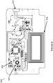
- FIG. 1 illustrates components of a mass flow controller 100 in accordance with the disclosed embodiments.
- mass flow controller 100 includes a block 110, which is the platform on which the components of the mass flow controller are mounted. The majority of the components of the MFC are integrated within a housing 104.
- a thermal mass flow meter 140 and a valve assembly 150 are mounted on the block 110 between a fluid inlet 120 and a fluid outlet 130. In other embodiments, the thermal mass flow meter 140 may be bolted directly to the valve assembly 150 without the use of the block 110.
- the valve assembly 150 includes a control valve 170. In certain embodiments, the control valve 170 may be one of a solenoid valve or a Piezo valve.
- the thermal mass flow meter 140 includes a bypass 142 through which typically a majority of fluid flows and a thermal flow sensor 146 through which a smaller portion of the fluid flows.
- Thermal flow sensor 146 is contained within a sensor housing 102 (portion shown removed to show sensor 146) mounted on a mounting plate or base 108.
- Sensor 146 is a small diameter tube, typically referred to as a capillary tube, with a sensor inlet portion 146A, a sensor outlet portion 146B, and a sensor measuring portion 146C about which two resistive coils or windings 147, 148 are disposed.
- electrical current is provided to the two resistive windings 147, 148, which are in thermal contact with the sensor measuring portion 146C.
- the current in the resistive windings 147, 148 heats the fluid flowing in measuring portion 146 to a temperature above that of the fluid flowing through the bypass 142.
- the resistance of windings 147, 148 varies with temperature. As fluid flows through the sensor conduit, heat is carried from the upstream resistor 147 toward the downstream resistor 148, with the temperature difference being proportional to the mass flow rate through the sensor.
- An electrical signal related to the fluid flow through the sensor is derived from the two resistive windings 147,148.
- the electrical signal may be derived in a number of different ways, such as from the difference in the resistance of the resistive windings or from a difference in the amount of energy provided to each resistive winding to maintain each winding at a particular temperature. Examples of various ways in which an electrical signal correlating to the flow rate of a fluid in a thermal mass flow meter may be determined are described, for example, in commonly owned U.S. Pat. No. 6,845,659 , which is hereby incorporated by reference.
- the electrical signals derived from the resistive windings 147,148 after signal processing comprise a sensor output signal.
- the sensor output signal is correlated to mass flow in the mass flow meter so that the fluid flow can be determined when the electrical signal is measured.
- the sensor output signal is typically first correlated to the flow in sensor 146, which is then correlated to the mass flow in the bypass 142, so that the total flow through the flow meter can be determined and the control valve 170 can be controlled accordingly.
- the correlation between the sensor output signal and the fluid flow is complex and depends on a number of operating conditions including fluid species, flow rate, inlet and/or outlet pressure, temperature, etc.
- a bypass 142 may then be mounted to the sensor, and the bypass 142 is tuned with the known fluid to determine an appropriate relationship between fluid flowing in the mass flow sensor and the fluid flowing in the bypass at various known flow rates, so that the total flow through the flow meter can be determined from the sensor output signal.
- no bypass is used, and the entire flow passes through the sensor.
- the mass flow sensor portion and bypass 142 may then be mated to the control valve and control electronics portions and then tuned again, under known conditions. The responses of the control electronics and the control valve are then characterized so that the overall response of the system to a change in set point or input pressure is known, and the response can be used to control the system to provide the desired response.
- the mass flow controller 100 may include a pressure transducer 112 coupled to flow path at some point, typically, but not limited to, upstream of the bypass 142 to measure pressure in the flow path.
- Pressure transducer 112 provides a pressure signal indicative of the pressure.
- Control electronics 160 is used to control the position of the control valve 170 in accordance with a set point indicating the desired mass flow rate, and an electrical flow signal from the mass flow sensor indicative of the actual mass flow rate of the fluid flowing in the sensor conduit.
- traditional feedback control methods such as proportional control, integral control, proportional-integral (PI) control, derivative control, proportional-derivative (PD) control, integral-derivative (ID) control, and proportional-integral-derivative (PID) control are then used to control the flow of fluid in the mass flow controller.
- Other embodiments may employ a model based controller that does not use any PID type control.
- a control signal (e.g., a control valve drive signal) is generated based upon an error signal that is the difference between a set point signal indicative of the desired mass flow rate of the fluid and a feedback signal that is related to the actual mass flow rate sensed by the mass flow sensor.
- the control valve is positioned in the main fluid flow path (typically downstream of the bypass and mass flow sensor) and can be controlled (e.g., opened or closed) to vary the mass flow rate of fluid flowing through the main fluid flow path, the control being provided by the mass flow controller.
- the flow rate is supplied by electrical conductors 158 to a closed loop system controller 160 as a voltage signal.
- the signal is amplified, processed and supplied using electrical conductors 159 to the valve assembly 150 to modify the flow.
- the controller 160 compares the signal from the mass flow sensor 140 to predetermined values and adjusts the control valve 170 accordingly to achieve the desired flow.
- the mass flow controller 100 may utilize other types of mass flow sensors including a Coriolis type sensor or a differential pressure type sensor.
- a Coriolis-based sensor is that it is capable of determining mass flow independent of temperature, flow profile, density, viscosity, and homogeneity.
- differential pressure type sensors are becoming popular for gas control.
- the mass flow controller 100 may include distributed electronics where the signals will be digital commands to and from the sensor and to and from the valve.
- a mass flow controller that enables the changing of settings within the MFC without the use of expensive switches and without requiring power cables.
- a mass flow controller is modified to include a Near Field Communication (NFC) circuit component 200 such as, but not limited to, the example printed circuit board (PCB) depicted in Figure 2 .
- NFC Near Field Communication
- NFC is a set of standards for smartphones and similar devices to establish radio communication with each other by touching them together or bringing them into close proximity, usually no more than a few centimeters.
- NFC standards cover communications protocols and data exchange formats, and are based on existing radio-frequency identification (RFID) standards.
- RFID radio-frequency identification
- Radio-frequency identification is the use of a wireless non-contact system that uses radio-frequency electromagnetic fields to transfer data from a tag attached to an object, for such purposes as, but not limited to, automatic identification and tracking.
- the NFC circuit component 200 includes an antenna 214 for providing a radio-frequency (RF) interface.
- RF radio-frequency
- the Near Field Communication (NFC) communication circuit component 200 may also include one or more of a microprocessor 202, a temperature sensor 204, a micro-electromechanical systems (MEMS) component 206.
- the NFC circuit component 200 may be configured in a RFID mode using a RFID communication interface switch 210 for reading and writing to the Electrically Erasable Programmable Read-Only Memory (EEPROM) 212 or other memory components.
- EEPROM Electrically Erasable Programmable Read-Only Memory
- the NFC circuit component 200 may be configured to read and write directly to a memory component of the MFC.
- the NFC circuit component 200 is used a means to provide power to the MFC.
- the limited amount of power available is sufficient to power the circuit in the MFC that is responsible for setting the MacID.
- the mass flow controller may include a LCD display that displays the MacID of the device, and may also include a set of push buttons used to change the MacID to the desired new value.
- the disclosed mass flow controller may then communicate with any device having an RFID reader. For example, most modern phones now provide a NFC power source. Also, any RFID wand reader and mouse pad type RFID reader could also be used.
- a mass flow controller is programmed to automatically execute an algorithm 300 when the NFC power is applied (step 302) to automatically display the current MacID or other settings (step 304).
- the algorithm 300 then adjusts the MacID or other settings based on user input (step 306).
- the MacID can be changed accordingly (up or down) using one or more push buttons located on the mass flow controller.
- the MacID may flash or provide some other indication that it is changing.
- the algorithm 300 writes the new value(s) to nonvolatile memory while being powered by the NFC source (step 308).
- a NFC host device could simply be positioned next to the MFC and the display would light up and show the current MacID.
- the MacID may be displayed on the host device.
- the host NFC device could also run an application or software that communicates over the NFC protocol to send new baud rate and MacID configuration settings to the mass flow controller. In this embodiment, physically touching the MFC is not necessary. Security can be handled through encryption.
- software running on the RFID reader (or an "app" on a smart phone) may be used to set certain parameters inside the MFC including, but not limited to, the MacID.
- the disclosed inventions include an MFC that includes one or more Universal Serial Bus (USB) connections 182 that will enable the use of off-the-shelf cables and hubs for manufacturing processes.
- USB Universal Serial Bus
- the USB connection 182 is positioned at the top of the mass flow controller. However, the USB connection 182 may be positioned elsewhere such as, but not limited to, one or more sides of the mass flow controller.
- the USB protocol is used to exchange or retrieve information with the MFC or configure the MFC (e.g., changing the MacID) without requiring the user to power up the MFC.
- the USB protocol allows for up to 500 mA at 5V, which is enough to power the logic components of the MFC without requiring an external power supply.
- the USB interface can be used to power the logic functions of the device to enable data exchange, but not the control portion of the device such as the valve or the sensors.
- the mass flow controller would execute instructions to use the USB cable to communicate from an external system (such as, but not limited to, a personal computer or laptop) to the MFC for all manufacturing processes, to setup Multiflo, or perform other customer configuration.
- an external system such as, but not limited to, a personal computer or laptop
- the MFC 410 may be connected though the USB cable 420 and appear on the host computer 430 as a COM port that can be accessed using existing software, so no changes are required on the host side.
- the MFC appears as a "mass storage device," for example, like a USB storage drive and the host computer could transfer data files to and from the device.
- data that can be transferred from the device include, but are not limited to: log files of past events, log files of previous recipes run on the device, and "black box recorder" type information.
- data that can be transferred to the device include, but are not limited to: future recipes to run, new calibration tables, new tuning tables, new gas tables for multi gas devices, data streaming logs, factory configuration etc.
- Firmware and databases can also be stored in protected area for retrieval by field service engineers. Data collection can be setup once or enabled by default and log files are created in the mass storage section of the device.
- the MFC could be powered though a "battery in a USB stick" module to enable settings of parameters as described in the NFC portion.
- a smart phone, tablet, or other mobile device could be connected to the MFC through the USB port to enable data exchange and device configuration using the mobile device.
- the MFC may act as a host while a standard USB memory stick is plugged into the device.
- the MFC can then be instructed, through various means, to transfer data to and or from the memory stick as described above already.
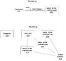
- Figure 5 illustrates an example of a multiple MFCs configuration for manufacturing.
- Power is provided by a separate power supply 510.
- the computer can calibrate or run other processes, simultaneously or one at a time, on multiple mass flow controllers such as, but not limited to, mass flow controllers 512-516.
- the mass flow controllers 512-516 may be connected directly to a host computer 520 or alternatively, the mass flow controllers 512-516 may be connected to a USB hub 518, which in turn is coupled to the host computer 520 as shown in Figure 5 .
- the disclosed inventions provide various embodiments of an MFC.
- Examples of the disclosed inventions include an MFC that enables changing of the MacID using near field communication.
- the disclosed inventions include an MFC that includes a standard USB connection that will enable the use of off the shelf cables and hubs for manufacturing processes.
- the MFC may be configured with both a NFC communication circuit component and a USB communication interface.
- MFC mass flow meter
- pressure gages pressure controller, variable area meter, pressure based MFC, or other similar measuring device.
- pressure controller variable area meter, pressure based MFC, or other similar measuring device.
Landscapes
- Engineering & Computer Science (AREA)
- Physics & Mathematics (AREA)
- General Physics & Mathematics (AREA)
- Automation & Control Theory (AREA)
- Computer Networks & Wireless Communication (AREA)
- Signal Processing (AREA)
- General Engineering & Computer Science (AREA)
- Flow Control (AREA)
Description
- The present invention relates generally to the operation of a mass flow controller (MFC). In particular, it relates to a mass flow controller as defined in the preamble of claim 1 and to a method for configuring a mass flow controller. Such a mass flow controller is known from
EP 1 790 898 A1 . - Many industrial processes require precise control of various process fluids. For example, in the semiconductor industries, mass flow controllers are used to precisely measure and control the amount of a process fluid that is introduced to a process chamber. The term fluid is used herein to describe any type of matter in any state that is capable of flow. For example, it is to be understood that the term fluid may apply to liquids, gases, vapors, and slurries comprising any combination of matter or substance to which controlled flow may be of interest.
- A mass flow controller according to the present invention comprises an inlet for receiving fluid; a flow path in which the fluid passes through the mass flow controller; a near-field communication component; a mass flow sensor for providing a signal corresponding to mass flow of the fluid through the flow path; a valve for regulating a flow of the fluid out of an outlet of the mass flow controller; and at least one processing component configured to execute instructions to perform operations comprising controlling the valve based on a desired mass flow rate. The mass flow controller automatically displays a current configuration parameter in response to receiving power from an external device using the near-field communication component of the mass flow controller, wherein the at least one processing component is configured to execute instructions to perform operations further comprising: adjusting the configuration parameter based on user input; and storing the configuration parameter in memory while being powered by the external device, wherein adjusting the configuration parameter based on user input is performed in response to receiving user input from one or more push buttons located on the mass flow controller.
- Illustrative embodiments of the present invention are described in detail below with reference to the attached figures, which are incorporated by reference herein and wherein:
-
Figure 1 is a diagram that illustrates components of a mass flow controller in accordance with the disclosed embodiments; -
Figure 2 is a diagram that illustrates an example of a Near Field Communication (NFC) circuit component in accordance with the disclosed embodiments; -
Figure 3 is a flow chart depicting a process for adjusting the parameters of a mass flow controller in accordance with the disclosed embodiments; -
Figure 4 is a diagram that illustrates an example a communication network using a mass flow controller having a standard Universal Serial Bus (USB) connection in accordance with the disclosed embodiments; and -
Figure 5 is a diagram that illustrates an example a communication network with multiple USB configured mass flow controllers in accordance with the disclosed embodiments. - Currently, mass flow controllers (MFCs) that have some electrical configuration (e.g., DeviceNet or EtherCAT) typically require Media Access Control Identifier (MacID) and baud rate configuration (individualized for each unit on a tool). This configuration process is currently being done using rotary switches that are customer accessible and require a screwdriver to modify. Using rotary switches to set the MacID is an expensive solution to the problem. In addition, the process requires openings in the MFC enclosure, which translates into cost (extra machining and labor), and source of electrical noise. Further, although using rotary switches to set MacID can be done without applying power, power is eventually needed to verify that the changes were made and took effect correctly.
- Additionally, MFCs with electrical configuration typically require custom cables and software to connect to, configure, and collect data from. Further, data collection currently requires a computer to be physically connected to the MFC to perform any real time data collection.
- Accordingly, the disclosed inventions seek to provide one more or solutions to the above problems. For instance, in one embodiment, the disclosed inventions include an MFC that enables changing of the MacID and baud rate settings without the use of expensive switches and without requiring power cables. In another embodiment, the disclosed inventions include an MFC that includes a standard Universal Serial Bus (USB) connection that will enable the use of off-the-shelf cables and hubs for manufacturing processes, data exchange, and communication while installed at the customer's site.
- The disclosed embodiments and advantages thereof are best understood by referring to
Figures 1-5 of the drawings, like numerals being used for like and corresponding parts of the various drawings. Other features and advantages of the disclosed embodiments will be or will become apparent to one of ordinary skill in the art upon examination of the following figures and detailed description -
Figure 1 illustrates components of amass flow controller 100 in accordance with the disclosed embodiments. In one embodiment,mass flow controller 100 includes ablock 110, which is the platform on which the components of the mass flow controller are mounted. The majority of the components of the MFC are integrated within ahousing 104. A thermalmass flow meter 140 and avalve assembly 150 are mounted on theblock 110 between afluid inlet 120 and afluid outlet 130. In other embodiments, the thermalmass flow meter 140 may be bolted directly to thevalve assembly 150 without the use of theblock 110. Thevalve assembly 150 includes acontrol valve 170. In certain embodiments, thecontrol valve 170 may be one of a solenoid valve or a Piezo valve. The thermalmass flow meter 140 includes abypass 142 through which typically a majority of fluid flows and athermal flow sensor 146 through which a smaller portion of the fluid flows. -
Thermal flow sensor 146 is contained within a sensor housing 102 (portion shown removed to show sensor 146) mounted on a mounting plate orbase 108.Sensor 146 is a small diameter tube, typically referred to as a capillary tube, with asensor inlet portion 146A, asensor outlet portion 146B, and asensor measuring portion 146C about which two resistive coils orwindings resistive windings sensor measuring portion 146C. The current in theresistive windings portion 146 to a temperature above that of the fluid flowing through thebypass 142. The resistance ofwindings upstream resistor 147 toward thedownstream resistor 148, with the temperature difference being proportional to the mass flow rate through the sensor. - An electrical signal related to the fluid flow through the sensor is derived from the two resistive windings 147,148. The electrical signal may be derived in a number of different ways, such as from the difference in the resistance of the resistive windings or from a difference in the amount of energy provided to each resistive winding to maintain each winding at a particular temperature. Examples of various ways in which an electrical signal correlating to the flow rate of a fluid in a thermal mass flow meter may be determined are described, for example, in commonly owned
U.S. Pat. No. 6,845,659 , which is hereby incorporated by reference. The electrical signals derived from the resistive windings 147,148 after signal processing comprise a sensor output signal. - The sensor output signal is correlated to mass flow in the mass flow meter so that the fluid flow can be determined when the electrical signal is measured. The sensor output signal is typically first correlated to the flow in
sensor 146, which is then correlated to the mass flow in thebypass 142, so that the total flow through the flow meter can be determined and thecontrol valve 170 can be controlled accordingly. The correlation between the sensor output signal and the fluid flow is complex and depends on a number of operating conditions including fluid species, flow rate, inlet and/or outlet pressure, temperature, etc. - A
bypass 142 may then be mounted to the sensor, and thebypass 142 is tuned with the known fluid to determine an appropriate relationship between fluid flowing in the mass flow sensor and the fluid flowing in the bypass at various known flow rates, so that the total flow through the flow meter can be determined from the sensor output signal. In some mass flow controllers, no bypass is used, and the entire flow passes through the sensor. The mass flow sensor portion andbypass 142 may then be mated to the control valve and control electronics portions and then tuned again, under known conditions. The responses of the control electronics and the control valve are then characterized so that the overall response of the system to a change in set point or input pressure is known, and the response can be used to control the system to provide the desired response. - In addition, the
mass flow controller 100 may include apressure transducer 112 coupled to flow path at some point, typically, but not limited to, upstream of thebypass 142 to measure pressure in the flow path.Pressure transducer 112 provides a pressure signal indicative of the pressure. -
Control electronics 160 is used to control the position of thecontrol valve 170 in accordance with a set point indicating the desired mass flow rate, and an electrical flow signal from the mass flow sensor indicative of the actual mass flow rate of the fluid flowing in the sensor conduit. In certain embodiments, traditional feedback control methods such as proportional control, integral control, proportional-integral (PI) control, derivative control, proportional-derivative (PD) control, integral-derivative (ID) control, and proportional-integral-derivative (PID) control are then used to control the flow of fluid in the mass flow controller. Other embodiments may employ a model based controller that does not use any PID type control. A control signal (e.g., a control valve drive signal) is generated based upon an error signal that is the difference between a set point signal indicative of the desired mass flow rate of the fluid and a feedback signal that is related to the actual mass flow rate sensed by the mass flow sensor. The control valve is positioned in the main fluid flow path (typically downstream of the bypass and mass flow sensor) and can be controlled (e.g., opened or closed) to vary the mass flow rate of fluid flowing through the main fluid flow path, the control being provided by the mass flow controller. - In the illustrated example, the flow rate is supplied by
electrical conductors 158 to a closedloop system controller 160 as a voltage signal. The signal is amplified, processed and supplied usingelectrical conductors 159 to thevalve assembly 150 to modify the flow. To this end, thecontroller 160 compares the signal from themass flow sensor 140 to predetermined values and adjusts thecontrol valve 170 accordingly to achieve the desired flow. - Although
Figure 1 depicts that themass flow controller 100 includes a thermal mass flow sensor, themass flow controller 100, in accordance with the disclosed embodiments, may utilize other types of mass flow sensors including a Coriolis type sensor or a differential pressure type sensor. An advantage of using a Coriolis-based sensor is that it is capable of determining mass flow independent of temperature, flow profile, density, viscosity, and homogeneity. Additionally, differential pressure type sensors are becoming popular for gas control. - Additionally, while the above description of the
mass flow controller 100 discloses the use of voltage signals, in certain embodiments, themass flow controller 100 may include distributed electronics where the signals will be digital commands to and from the sensor and to and from the valve. - As stated above, in accordance with one embodiment, a mass flow controller is disclosed that enables the changing of settings within the MFC without the use of expensive switches and without requiring power cables. For example, in one embodiment, a mass flow controller is modified to include a Near Field Communication (NFC)
circuit component 200 such as, but not limited to, the example printed circuit board (PCB) depicted inFigure 2 . - NFC is a set of standards for smartphones and similar devices to establish radio communication with each other by touching them together or bringing them into close proximity, usually no more than a few centimeters. NFC standards cover communications protocols and data exchange formats, and are based on existing radio-frequency identification (RFID) standards. Radio-frequency identification is the use of a wireless non-contact system that uses radio-frequency electromagnetic fields to transfer data from a tag attached to an object, for such purposes as, but not limited to, automatic identification and tracking. For instance, in one embodiment, the
NFC circuit component 200 includes anantenna 214 for providing a radio-frequency (RF) interface. - In one embodiment, the Near Field Communication (NFC)
communication circuit component 200 may also include one or more of amicroprocessor 202, atemperature sensor 204, a micro-electromechanical systems (MEMS)component 206. In certain embodiments, theNFC circuit component 200 may be configured in a RFID mode using a RFIDcommunication interface switch 210 for reading and writing to the Electrically Erasable Programmable Read-Only Memory (EEPROM) 212 or other memory components. Alternatively, in some embodiments, theNFC circuit component 200 may be configured to read and write directly to a memory component of the MFC. - In a first embodiment, the
NFC circuit component 200 is used a means to provide power to the MFC. In one embodiment, the limited amount of power available is sufficient to power the circuit in the MFC that is responsible for setting the MacID. In this embodiment, the mass flow controller may include a LCD display that displays the MacID of the device, and may also include a set of push buttons used to change the MacID to the desired new value. The disclosed mass flow controller may then communicate with any device having an RFID reader. For example, most modern phones now provide a NFC power source. Also, any RFID wand reader and mouse pad type RFID reader could also be used. - In one embodiment, as depicted in
Figure 3 , a mass flow controller is programmed to automatically execute analgorithm 300 when the NFC power is applied (step 302) to automatically display the current MacID or other settings (step 304). Thealgorithm 300 then adjusts the MacID or other settings based on user input (step 306). For example, in one embodiment, the MacID can be changed accordingly (up or down) using one or more push buttons located on the mass flow controller. In certain embodiments, the MacID may flash or provide some other indication that it is changing. Afterwards, thealgorithm 300 writes the new value(s) to nonvolatile memory while being powered by the NFC source (step 308). To simply check on the settings, a NFC host device could simply be positioned next to the MFC and the display would light up and show the current MacID. In certain embodiments, the MacID may be displayed on the host device. - In a second embodiment, the host NFC device could also run an application or software that communicates over the NFC protocol to send new baud rate and MacID configuration settings to the mass flow controller. In this embodiment, physically touching the MFC is not necessary. Security can be handled through encryption. In one embodiment, software running on the RFID reader (or an "app" on a smart phone) may be used to set certain parameters inside the MFC including, but not limited to, the MacID.
- Still, in another embodiment, the disclosed inventions include an MFC that includes one or more Universal Serial Bus (USB)
connections 182 that will enable the use of off-the-shelf cables and hubs for manufacturing processes. In one embodiment, theUSB connection 182 is positioned at the top of the mass flow controller. However, theUSB connection 182 may be positioned elsewhere such as, but not limited to, one or more sides of the mass flow controller. - In one embodiment, the USB protocol is used to exchange or retrieve information with the MFC or configure the MFC (e.g., changing the MacID) without requiring the user to power up the MFC. For example, the USB protocol allows for up to 500 mA at 5V, which is enough to power the logic components of the MFC without requiring an external power supply. The USB interface can be used to power the logic functions of the device to enable data exchange, but not the control portion of the device such as the valve or the sensors.
- The mass flow controller would execute instructions to use the USB cable to communicate from an external system (such as, but not limited to, a personal computer or laptop) to the MFC for all manufacturing processes, to setup Multiflo, or perform other customer configuration. In one embodiment, as depicted in
Figure 4 , theMFC 410 may be connected though theUSB cable 420 and appear on thehost computer 430 as a COM port that can be accessed using existing software, so no changes are required on the host side. One advantage of the above configuration is that it allows for existing manufacturing process to take advantage of the new technology while being compatible with installed software. - In another embodiment, the MFC appears as a "mass storage device," for example, like a USB storage drive and the host computer could transfer data files to and from the device. Examples of data that can be transferred from the device include, but are not limited to: log files of past events, log files of previous recipes run on the device, and "black box recorder" type information. Examples of data that can be transferred to the device include, but are not limited to: future recipes to run, new calibration tables, new tuning tables, new gas tables for multi gas devices, data streaming logs, factory configuration etc. Firmware and databases can also be stored in protected area for retrieval by field service engineers. Data collection can be setup once or enabled by default and log files are created in the mass storage section of the device.
- In another embodiment, the MFC could be powered though a "battery in a USB stick" module to enable settings of parameters as described in the NFC portion. In another embodiment a smart phone, tablet, or other mobile device could be connected to the MFC through the USB port to enable data exchange and device configuration using the mobile device.
- Still, in another embodiment, the MFC may act as a host while a standard USB memory stick is plugged into the device. The MFC can then be instructed, through various means, to transfer data to and or from the memory stick as described above already.
-
Figure 5 illustrates an example of a multiple MFCs configuration for manufacturing. Power is provided by aseparate power supply 510. In one embodiment, the computer can calibrate or run other processes, simultaneously or one at a time, on multiple mass flow controllers such as, but not limited to, mass flow controllers 512-516. The mass flow controllers 512-516 may be connected directly to ahost computer 520 or alternatively, the mass flow controllers 512-516 may be connected to a USB hub 518, which in turn is coupled to thehost computer 520 as shown inFigure 5 . - Accordingly, the disclosed inventions provide various embodiments of an MFC. Examples of the disclosed inventions include an MFC that enables changing of the MacID using near field communication. In another embodiment, the disclosed inventions include an MFC that includes a standard USB connection that will enable the use of off the shelf cables and hubs for manufacturing processes. Still, in certain embodiments, the MFC may be configured with both a NFC communication circuit component and a USB communication interface.
- Those skilled in the art will recognize that the present teachings are amenable to a variety of modifications and/or enhancements. For instance, while the above description specifically describes an MFC, one of ordinary skill in the art would recognize that certain of the disclosed embodiments may also be implemented in a mass flow meter (MFM), pressure gages, pressure controller, variable area meter, pressure based MFC, or other similar measuring device.
gages, pressure controller, variable area meter, pressure based MFC, or other similar measuring device.
Claims (9)
- A mass flow controller (100) comprising:an inlet (120) for receiving fluid;a flow path in which the fluid passes through the mass flow controller (100);a near-field communication component (200);a mass flow sensor (146) for providing a signal corresponding to mass flow of the fluid through the flow path;a valve (170) for regulating a flow of the fluid out of an outlet of the mass flow controller (100); andat least one processing component (160) configured to execute instructions to perform operations comprising controlling the valve (170) based on a desired mass flow rate,characterized by
automatically displaying a current configuration parameter of the mass flow controller (100) in response to receiving power from an external device using the near-field communication component (200) of the mass flow controller (100),
wherein the at least one processing component (160) is configured to execute instructions to perform operations further comprising:adjusting the configuration parameter based on user input; andstoring the configuration parameter in memory while being powered by the external device,wherein adjusting the configuration parameter based on user input is performed in response to receiving user input from one or more push buttons located on the mass flow controller (100). - The mass flow controller of Claim 1, wherein the configuration parameter is a media access control identifier of the mass flow controller (100).
- The mass flow controller of one of the preceding Claims, wherein the configuration parameter is a baud rate of the mass flow controller (100).
- The mass flow controller of one of Claims1 to 3, wherein adjusting the configuration parameter based on user input is performed in response to receiving the configuration parameters from the external device.
- The mass flow controller of one of the preceding claims, further comprising a universal serial bus communication interface (182);
the at least one processing component (160) configured to execute instructions to perform operations comprising automatically displaying a current configuration parameter in response to receiving power from an external device through the universal serial bus communication interface (182) of the mass flow controller (100). - A method for configuring a mass flow controller (100), the method comprising:automatically displaying a current configuration parameter in response to receiving power at a communication interface of the mass flow controller (100)from an external device;adjusting the configuration parameter based on user input; andstoring the configuration parameter in memory while being powered by the external device;wherein the communication interface that provides power to the mass flow controller is a near-field communication interface (200) and/ or a universal serial bus communication interface (182),
wherein adjusting the configuration parameter based on user input is performed in response to receiving user input from one or more push buttons located on the mass flow controller (100). - The method of Claim 6, wherein the configuration parameter is a media access control identifier of the mass flow controller (100).
- The method of Claim 6, wherein the configuration parameter is a baud rate of the mass flow controller (100).
- The method of one of Claims 6 to 8, wherein adjusting the configuration parameter based on user input is performed in response to receiving the configuration parameters from the external device.
Applications Claiming Priority (2)
| Application Number | Priority Date | Filing Date | Title |
|---|---|---|---|
| US201361777224P | 2013-03-12 | 2013-03-12 | |
| PCT/US2014/021976 WO2014164336A1 (en) | 2013-03-12 | 2014-03-07 | Mass flow controller with near field communication and/or usb interface |
Publications (2)
| Publication Number | Publication Date |
|---|---|
| EP2972630A1 EP2972630A1 (en) | 2016-01-20 |
| EP2972630B1 true EP2972630B1 (en) | 2019-01-16 |
Family
ID=50391476
Family Applications (1)
| Application Number | Title | Priority Date | Filing Date |
|---|---|---|---|
| EP14714069.3A Active EP2972630B1 (en) | 2013-03-12 | 2014-03-07 | Mass flow controller with near field communication and/or usb interface |
Country Status (4)
| Country | Link |
|---|---|
| US (1) | US10114387B2 (en) |
| EP (1) | EP2972630B1 (en) |
| JP (1) | JP6408550B2 (en) |
| WO (1) | WO2014164336A1 (en) |
Families Citing this family (9)
| Publication number | Priority date | Publication date | Assignee | Title |
|---|---|---|---|---|
| US9732977B2 (en) | 2014-09-02 | 2017-08-15 | Johnson Controls Technology Company | Systems and methods for configuring and communicating with HVAC devices |
| US10409295B2 (en) * | 2016-12-31 | 2019-09-10 | Applied Materials, Inc. | Methods and apparatus for enhanced flow detection repeatability of thermal-based mass flow controllers (MFCS) |
| US10983537B2 (en) | 2017-02-27 | 2021-04-20 | Flow Devices And Systems Inc. | Systems and methods for flow sensor back pressure adjustment for mass flow controller |
| WO2018174701A1 (en) * | 2017-03-22 | 2018-09-27 | MONTOYA BUGARÍN, Maurilio | Automated device and system for remotely controlling the distribution of fluids |
| US10783290B2 (en) * | 2017-09-28 | 2020-09-22 | Taiwan Semiconductor Manufacturing Company, Ltd. | IC manufacturing recipe similarity evaluation methods and systems |
| CN109978486A (en) * | 2017-12-28 | 2019-07-05 | 北京京东尚科信息技术有限公司 | Method, apparatus, system and medium for Row control |
| JP7382339B2 (en) * | 2018-03-30 | 2023-11-16 | ラム リサーチ コーポレーション | Coriolis mass flow controller based on MEMS |
| DE102018111547A1 (en) * | 2018-05-15 | 2019-11-21 | E. Zoller Gmbh & Co. Kg | Method for transmitting at least one stored on a storage medium tool data set of a cutting tool to a CNC machine tool with a data communication unit |
| EP4330777A1 (en) * | 2021-04-30 | 2024-03-06 | GEA Tuchenhagen GmbH | Valve control device |
Citations (2)
| Publication number | Priority date | Publication date | Assignee | Title |
|---|---|---|---|---|
| WO2004010234A2 (en) * | 2002-07-19 | 2004-01-29 | Celerity Group, Inc. | Methods and apparatus for pressure compensation in a mass flow controller |
| US20100190436A1 (en) * | 2008-08-26 | 2010-07-29 | Qualcomm Incorporated | Concurrent wireless power transmission and near-field communication |
Family Cites Families (19)
| Publication number | Priority date | Publication date | Assignee | Title |
|---|---|---|---|---|
| US5080131A (en) * | 1989-09-26 | 1992-01-14 | Lintec Co., Ltd. | Mass flow controller |
| US5062446A (en) | 1991-01-07 | 1991-11-05 | Sematech, Inc. | Intelligent mass flow controller |
| US6810308B2 (en) | 2002-06-24 | 2004-10-26 | Mks Instruments, Inc. | Apparatus and method for mass flow controller with network access to diagnostics |
| US7004191B2 (en) | 2002-06-24 | 2006-02-28 | Mks Instruments, Inc. | Apparatus and method for mass flow controller with embedded web server |
| US7809473B2 (en) * | 2002-06-24 | 2010-10-05 | Mks Instruments, Inc. | Apparatus and method for pressure fluctuation insensitive mass flow control |
| US7136767B2 (en) | 2002-06-24 | 2006-11-14 | Mks Instruments, Inc. | Apparatus and method for calibration of mass flow controller |
| US6845659B2 (en) | 2002-07-19 | 2005-01-25 | Celerity Group, Inc. | Variable resistance sensor with common reference leg |
| US6843139B2 (en) | 2003-03-12 | 2005-01-18 | Rosemount Inc. | Flow instrument with multisensors |
| JP2006083959A (en) | 2004-09-16 | 2006-03-30 | Fujikin Inc | Joint member with sensor |
| US20060249507A1 (en) | 2005-04-11 | 2006-11-09 | Watlow Electric Manufacturing Company | Modular controller user interface and method |
| US20080147332A1 (en) * | 2006-12-14 | 2008-06-19 | Arikara Muralidharan P | System for and method of fluid delivery, monitoring and/or mangement |
| US7874208B2 (en) | 2007-10-10 | 2011-01-25 | Brooks Instrument, Llc | System for and method of providing a wide-range flow controller |
| US7769493B2 (en) * | 2008-03-19 | 2010-08-03 | King Fahd University Of Petroleum And Minerals | System and method for controlling flow characteristics |
| US20090303013A1 (en) * | 2008-06-05 | 2009-12-10 | The University Of Akron | Systems and methods for wireless control of equipment |
| FR2938096B1 (en) * | 2008-11-03 | 2010-11-26 | Oberthur Technologies | ELECTRONIC DEVICE ALLOWING NEAR - FIELD CONTACT - FREE COMMUNICATIONS. |
| US8224246B2 (en) | 2010-05-10 | 2012-07-17 | Nokia Corporation | Device to device connection setup using near-field communication |
| WO2012011289A1 (en) * | 2010-07-23 | 2012-01-26 | パナソニック株式会社 | Nfc communication apparatus and method for controlling same |
| WO2014059359A1 (en) * | 2012-10-11 | 2014-04-17 | Marinez Luis | Intelligent valve network |
| US9146563B2 (en) * | 2013-03-01 | 2015-09-29 | Hitachi Metals, Ltd. | Mass flow controller and method for improved performance across fluid types |
-
2014
- 2014-03-07 JP JP2016500888A patent/JP6408550B2/en active Active
- 2014-03-07 US US14/772,868 patent/US10114387B2/en active Active
- 2014-03-07 WO PCT/US2014/021976 patent/WO2014164336A1/en active Application Filing
- 2014-03-07 EP EP14714069.3A patent/EP2972630B1/en active Active
Patent Citations (2)
| Publication number | Priority date | Publication date | Assignee | Title |
|---|---|---|---|---|
| WO2004010234A2 (en) * | 2002-07-19 | 2004-01-29 | Celerity Group, Inc. | Methods and apparatus for pressure compensation in a mass flow controller |
| US20100190436A1 (en) * | 2008-08-26 | 2010-07-29 | Qualcomm Incorporated | Concurrent wireless power transmission and near-field communication |
Also Published As
| Publication number | Publication date |
|---|---|
| EP2972630A1 (en) | 2016-01-20 |
| WO2014164336A1 (en) | 2014-10-09 |
| US20160018829A1 (en) | 2016-01-21 |
| JP6408550B2 (en) | 2018-10-17 |
| US10114387B2 (en) | 2018-10-30 |
| JP2016514331A (en) | 2016-05-19 |
Similar Documents
| Publication | Publication Date | Title |
|---|---|---|
| EP2972630B1 (en) | Mass flow controller with near field communication and/or usb interface | |
| EP2005765B1 (en) | System and method for identification of process components | |
| CN105324725B (en) | Control device, component and mobile service device for HVAC facilities | |
| US10048105B2 (en) | System and method for providing a self validating mass flow controller and mass flow meter | |
| JP6014705B2 (en) | Equipment with process diagnosis | |
| KR100718209B1 (en) | Mass flow controller, method for regulating the flow of mass through a mass flow controller and method for calibrating a mass flow controller | |
| EP2628060B1 (en) | Field device with self description | |
| WO2008063270A2 (en) | Adapter for providing digital communication between a field device and a computer | |
| EP1314044A2 (en) | Controlling of the temperature of a dut using external current sensors | |
| CN101655483A (en) | Column temperature monitoring apparatus and chromatographic apparatus | |
| US20190050003A1 (en) | Systems and methods to dynamically configure data values stored on a mass flow controller | |
| US20150113180A1 (en) | Method for Servicing a Field Device | |
| EP3871059B1 (en) | Mass flow controller with advanced zero trending diagnostics | |
| US20210231335A1 (en) | Intelligent measuring apparatus | |
| KR20170075333A (en) | A smart control device for use in an air conditioner for heating and cooling and energy management system | |
| EP2612209B1 (en) | A valve system | |
| US20160003492A1 (en) | Thermistor Emulating CT Clamp | |
| US20200132536A1 (en) | Mass flow controller with advanced back streaming diagnostics | |
| US9410834B2 (en) | System and method for providing a self validating mass flow controller or a mass flow meter utilizing a software protocol | |
| CN203771715U (en) | Display control device of water heater and gas water heater with same |
Legal Events
| Date | Code | Title | Description |
|---|---|---|---|
| PUAI | Public reference made under article 153(3) epc to a published international application that has entered the european phase |
Free format text: ORIGINAL CODE: 0009012 |
|
| 17P | Request for examination filed |
Effective date: 20150819 |
|
| AK | Designated contracting states |
Kind code of ref document: A1 Designated state(s): AL AT BE BG CH CY CZ DE DK EE ES FI FR GB GR HR HU IE IS IT LI LT LU LV MC MK MT NL NO PL PT RO RS SE SI SK SM TR |
|
| AX | Request for extension of the european patent |
Extension state: BA ME |
|
| DAX | Request for extension of the european patent (deleted) | ||
| STAA | Information on the status of an ep patent application or granted ep patent |
Free format text: STATUS: EXAMINATION IS IN PROGRESS |
|
| 17Q | First examination report despatched |
Effective date: 20180209 |
|
| REG | Reference to a national code |
Ref country code: DE Ref legal event code: R079 Ref document number: 602014039961 Country of ref document: DE Free format text: PREVIOUS MAIN CLASS: G05D0007060000 Ipc: H04W0004800000 |
|
| GRAP | Despatch of communication of intention to grant a patent |
Free format text: ORIGINAL CODE: EPIDOSNIGR1 |
|
| STAA | Information on the status of an ep patent application or granted ep patent |
Free format text: STATUS: GRANT OF PATENT IS INTENDED |
|
| RIC1 | Information provided on ipc code assigned before grant |
Ipc: G05D 7/06 20060101ALI20180829BHEP Ipc: G05B 15/02 20060101ALI20180829BHEP Ipc: H04W 4/80 20180101AFI20180829BHEP |
|
| INTG | Intention to grant announced |
Effective date: 20180920 |
|
| RIN1 | Information on inventor provided before grant (corrected) |
Inventor name: ELLEC, CHRISTOPHE Inventor name: BANARES, BERWIN |
|
| GRAS | Grant fee paid |
Free format text: ORIGINAL CODE: EPIDOSNIGR3 |
|
| GRAA | (expected) grant |
Free format text: ORIGINAL CODE: 0009210 |
|
| STAA | Information on the status of an ep patent application or granted ep patent |
Free format text: STATUS: THE PATENT HAS BEEN GRANTED |
|
| AK | Designated contracting states |
Kind code of ref document: B1 Designated state(s): AL AT BE BG CH CY CZ DE DK EE ES FI FR GB GR HR HU IE IS IT LI LT LU LV MC MK MT NL NO PL PT RO RS SE SI SK SM TR |
|
| REG | Reference to a national code |
Ref country code: GB Ref legal event code: FG4D |
|
| REG | Reference to a national code |
Ref country code: CH Ref legal event code: EP |
|
| REG | Reference to a national code |
Ref country code: IE Ref legal event code: FG4D |
|
| REG | Reference to a national code |
Ref country code: DE Ref legal event code: R096 Ref document number: 602014039961 Country of ref document: DE |
|
| REG | Reference to a national code |
Ref country code: AT Ref legal event code: REF Ref document number: 1090660 Country of ref document: AT Kind code of ref document: T Effective date: 20190215 |
|
| REG | Reference to a national code |
Ref country code: NL Ref legal event code: MP Effective date: 20190116 |
|
| REG | Reference to a national code |
Ref country code: LT Ref legal event code: MG4D |
|
| PG25 | Lapsed in a contracting state [announced via postgrant information from national office to epo] |
Ref country code: NL Free format text: LAPSE BECAUSE OF FAILURE TO SUBMIT A TRANSLATION OF THE DESCRIPTION OR TO PAY THE FEE WITHIN THE PRESCRIBED TIME-LIMIT Effective date: 20190116 |
|
| REG | Reference to a national code |
Ref country code: AT Ref legal event code: MK05 Ref document number: 1090660 Country of ref document: AT Kind code of ref document: T Effective date: 20190116 |
|
| PG25 | Lapsed in a contracting state [announced via postgrant information from national office to epo] |
Ref country code: ES Free format text: LAPSE BECAUSE OF FAILURE TO SUBMIT A TRANSLATION OF THE DESCRIPTION OR TO PAY THE FEE WITHIN THE PRESCRIBED TIME-LIMIT Effective date: 20190116 Ref country code: NO Free format text: LAPSE BECAUSE OF FAILURE TO SUBMIT A TRANSLATION OF THE DESCRIPTION OR TO PAY THE FEE WITHIN THE PRESCRIBED TIME-LIMIT Effective date: 20190416 Ref country code: FI Free format text: LAPSE BECAUSE OF FAILURE TO SUBMIT A TRANSLATION OF THE DESCRIPTION OR TO PAY THE FEE WITHIN THE PRESCRIBED TIME-LIMIT Effective date: 20190116 Ref country code: LT Free format text: LAPSE BECAUSE OF FAILURE TO SUBMIT A TRANSLATION OF THE DESCRIPTION OR TO PAY THE FEE WITHIN THE PRESCRIBED TIME-LIMIT Effective date: 20190116 Ref country code: PL Free format text: LAPSE BECAUSE OF FAILURE TO SUBMIT A TRANSLATION OF THE DESCRIPTION OR TO PAY THE FEE WITHIN THE PRESCRIBED TIME-LIMIT Effective date: 20190116 Ref country code: SE Free format text: LAPSE BECAUSE OF FAILURE TO SUBMIT A TRANSLATION OF THE DESCRIPTION OR TO PAY THE FEE WITHIN THE PRESCRIBED TIME-LIMIT Effective date: 20190116 Ref country code: PT Free format text: LAPSE BECAUSE OF FAILURE TO SUBMIT A TRANSLATION OF THE DESCRIPTION OR TO PAY THE FEE WITHIN THE PRESCRIBED TIME-LIMIT Effective date: 20190516 |
|
| PG25 | Lapsed in a contracting state [announced via postgrant information from national office to epo] |
Ref country code: BG Free format text: LAPSE BECAUSE OF FAILURE TO SUBMIT A TRANSLATION OF THE DESCRIPTION OR TO PAY THE FEE WITHIN THE PRESCRIBED TIME-LIMIT Effective date: 20190416 Ref country code: GR Free format text: LAPSE BECAUSE OF FAILURE TO SUBMIT A TRANSLATION OF THE DESCRIPTION OR TO PAY THE FEE WITHIN THE PRESCRIBED TIME-LIMIT Effective date: 20190417 Ref country code: HR Free format text: LAPSE BECAUSE OF FAILURE TO SUBMIT A TRANSLATION OF THE DESCRIPTION OR TO PAY THE FEE WITHIN THE PRESCRIBED TIME-LIMIT Effective date: 20190116 Ref country code: RS Free format text: LAPSE BECAUSE OF FAILURE TO SUBMIT A TRANSLATION OF THE DESCRIPTION OR TO PAY THE FEE WITHIN THE PRESCRIBED TIME-LIMIT Effective date: 20190116 Ref country code: IS Free format text: LAPSE BECAUSE OF FAILURE TO SUBMIT A TRANSLATION OF THE DESCRIPTION OR TO PAY THE FEE WITHIN THE PRESCRIBED TIME-LIMIT Effective date: 20190516 Ref country code: LV Free format text: LAPSE BECAUSE OF FAILURE TO SUBMIT A TRANSLATION OF THE DESCRIPTION OR TO PAY THE FEE WITHIN THE PRESCRIBED TIME-LIMIT Effective date: 20190116 |
|
| REG | Reference to a national code |
Ref country code: DE Ref legal event code: R097 Ref document number: 602014039961 Country of ref document: DE |
|
| PG25 | Lapsed in a contracting state [announced via postgrant information from national office to epo] |
Ref country code: IT Free format text: LAPSE BECAUSE OF FAILURE TO SUBMIT A TRANSLATION OF THE DESCRIPTION OR TO PAY THE FEE WITHIN THE PRESCRIBED TIME-LIMIT Effective date: 20190116 Ref country code: RO Free format text: LAPSE BECAUSE OF FAILURE TO SUBMIT A TRANSLATION OF THE DESCRIPTION OR TO PAY THE FEE WITHIN THE PRESCRIBED TIME-LIMIT Effective date: 20190116 Ref country code: CZ Free format text: LAPSE BECAUSE OF FAILURE TO SUBMIT A TRANSLATION OF THE DESCRIPTION OR TO PAY THE FEE WITHIN THE PRESCRIBED TIME-LIMIT Effective date: 20190116 Ref country code: SK Free format text: LAPSE BECAUSE OF FAILURE TO SUBMIT A TRANSLATION OF THE DESCRIPTION OR TO PAY THE FEE WITHIN THE PRESCRIBED TIME-LIMIT Effective date: 20190116 Ref country code: AT Free format text: LAPSE BECAUSE OF FAILURE TO SUBMIT A TRANSLATION OF THE DESCRIPTION OR TO PAY THE FEE WITHIN THE PRESCRIBED TIME-LIMIT Effective date: 20190116 Ref country code: MC Free format text: LAPSE BECAUSE OF FAILURE TO SUBMIT A TRANSLATION OF THE DESCRIPTION OR TO PAY THE FEE WITHIN THE PRESCRIBED TIME-LIMIT Effective date: 20190116 Ref country code: AL Free format text: LAPSE BECAUSE OF FAILURE TO SUBMIT A TRANSLATION OF THE DESCRIPTION OR TO PAY THE FEE WITHIN THE PRESCRIBED TIME-LIMIT Effective date: 20190116 Ref country code: EE Free format text: LAPSE BECAUSE OF FAILURE TO SUBMIT A TRANSLATION OF THE DESCRIPTION OR TO PAY THE FEE WITHIN THE PRESCRIBED TIME-LIMIT Effective date: 20190116 Ref country code: DK Free format text: LAPSE BECAUSE OF FAILURE TO SUBMIT A TRANSLATION OF THE DESCRIPTION OR TO PAY THE FEE WITHIN THE PRESCRIBED TIME-LIMIT Effective date: 20190116 |
|
| REG | Reference to a national code |
Ref country code: CH Ref legal event code: PL |
|
| PLBE | No opposition filed within time limit |
Free format text: ORIGINAL CODE: 0009261 |
|
| STAA | Information on the status of an ep patent application or granted ep patent |
Free format text: STATUS: NO OPPOSITION FILED WITHIN TIME LIMIT |
|
| PG25 | Lapsed in a contracting state [announced via postgrant information from national office to epo] |
Ref country code: SM Free format text: LAPSE BECAUSE OF FAILURE TO SUBMIT A TRANSLATION OF THE DESCRIPTION OR TO PAY THE FEE WITHIN THE PRESCRIBED TIME-LIMIT Effective date: 20190116 Ref country code: LU Free format text: LAPSE BECAUSE OF NON-PAYMENT OF DUE FEES Effective date: 20190307 |
|
| REG | Reference to a national code |
Ref country code: BE Ref legal event code: MM Effective date: 20190331 |
|
| 26N | No opposition filed |
Effective date: 20191017 |
|
| PG25 | Lapsed in a contracting state [announced via postgrant information from national office to epo] |
Ref country code: LI Free format text: LAPSE BECAUSE OF NON-PAYMENT OF DUE FEES Effective date: 20190331 Ref country code: CH Free format text: LAPSE BECAUSE OF NON-PAYMENT OF DUE FEES Effective date: 20190331 |
|
| PG25 | Lapsed in a contracting state [announced via postgrant information from national office to epo] |
Ref country code: SI Free format text: LAPSE BECAUSE OF FAILURE TO SUBMIT A TRANSLATION OF THE DESCRIPTION OR TO PAY THE FEE WITHIN THE PRESCRIBED TIME-LIMIT Effective date: 20190116 Ref country code: BE Free format text: LAPSE BECAUSE OF NON-PAYMENT OF DUE FEES Effective date: 20190331 |
|
| PG25 | Lapsed in a contracting state [announced via postgrant information from national office to epo] |
Ref country code: TR Free format text: LAPSE BECAUSE OF FAILURE TO SUBMIT A TRANSLATION OF THE DESCRIPTION OR TO PAY THE FEE WITHIN THE PRESCRIBED TIME-LIMIT Effective date: 20190116 |
|
| PG25 | Lapsed in a contracting state [announced via postgrant information from national office to epo] |
Ref country code: MT Free format text: LAPSE BECAUSE OF NON-PAYMENT OF DUE FEES Effective date: 20190307 |
|
| PG25 | Lapsed in a contracting state [announced via postgrant information from national office to epo] |
Ref country code: CY Free format text: LAPSE BECAUSE OF FAILURE TO SUBMIT A TRANSLATION OF THE DESCRIPTION OR TO PAY THE FEE WITHIN THE PRESCRIBED TIME-LIMIT Effective date: 20190116 |
|
| PG25 | Lapsed in a contracting state [announced via postgrant information from national office to epo] |
Ref country code: HU Free format text: LAPSE BECAUSE OF FAILURE TO SUBMIT A TRANSLATION OF THE DESCRIPTION OR TO PAY THE FEE WITHIN THE PRESCRIBED TIME-LIMIT; INVALID AB INITIO Effective date: 20140307 |
|
| PG25 | Lapsed in a contracting state [announced via postgrant information from national office to epo] |
Ref country code: MK Free format text: LAPSE BECAUSE OF FAILURE TO SUBMIT A TRANSLATION OF THE DESCRIPTION OR TO PAY THE FEE WITHIN THE PRESCRIBED TIME-LIMIT Effective date: 20190116 |
|
| PGFP | Annual fee paid to national office [announced via postgrant information from national office to epo] |
Ref country code: IE Payment date: 20230327 Year of fee payment: 10 Ref country code: FR Payment date: 20230327 Year of fee payment: 10 |
|
| PGFP | Annual fee paid to national office [announced via postgrant information from national office to epo] |
Ref country code: GB Payment date: 20230327 Year of fee payment: 10 Ref country code: DE Payment date: 20230329 Year of fee payment: 10 |
|
| P01 | Opt-out of the competence of the unified patent court (upc) registered |
Effective date: 20230606 |
|
| PGFP | Annual fee paid to national office [announced via postgrant information from national office to epo] |
Ref country code: IE Payment date: 20240327 Year of fee payment: 11 |