EP2972096B1 - Automatic driving route planning application - Google Patents
Automatic driving route planning application Download PDFInfo
- Publication number
- EP2972096B1 EP2972096B1 EP14708839.7A EP14708839A EP2972096B1 EP 2972096 B1 EP2972096 B1 EP 2972096B1 EP 14708839 A EP14708839 A EP 14708839A EP 2972096 B1 EP2972096 B1 EP 2972096B1
- Authority
- EP
- European Patent Office
- Prior art keywords
- route
- vehicle
- routes
- value
- data
- Prior art date
- Legal status (The legal status is an assumption and is not a legal conclusion. Google has not performed a legal analysis and makes no representation as to the accuracy of the status listed.)
- Active
Links
Images


Classifications
-
- G—PHYSICS
- G01—MEASURING; TESTING
- G01C—MEASURING DISTANCES, LEVELS OR BEARINGS; SURVEYING; NAVIGATION; GYROSCOPIC INSTRUMENTS; PHOTOGRAMMETRY OR VIDEOGRAMMETRY
- G01C21/00—Navigation; Navigational instruments not provided for in groups G01C1/00 - G01C19/00
- G01C21/26—Navigation; Navigational instruments not provided for in groups G01C1/00 - G01C19/00 specially adapted for navigation in a road network
- G01C21/34—Route searching; Route guidance
- G01C21/3453—Special cost functions, i.e. other than distance or default speed limit of road segments
-
- G—PHYSICS
- G01—MEASURING; TESTING
- G01C—MEASURING DISTANCES, LEVELS OR BEARINGS; SURVEYING; NAVIGATION; GYROSCOPIC INSTRUMENTS; PHOTOGRAMMETRY OR VIDEOGRAMMETRY
- G01C21/00—Navigation; Navigational instruments not provided for in groups G01C1/00 - G01C19/00
- G01C21/26—Navigation; Navigational instruments not provided for in groups G01C1/00 - G01C19/00 specially adapted for navigation in a road network
- G01C21/34—Route searching; Route guidance
- G01C21/36—Input/output arrangements for on-board computers
- G01C21/3667—Display of a road map
- G01C21/3676—Overview of the route on the road map
-
- G—PHYSICS
- G05—CONTROLLING; REGULATING
- G05D—SYSTEMS FOR CONTROLLING OR REGULATING NON-ELECTRIC VARIABLES
- G05D1/00—Control of position, course or altitude of land, water, air, or space vehicles, e.g. automatic pilot
- G05D1/02—Control of position or course in two dimensions
-
- G—PHYSICS
- G01—MEASURING; TESTING
- G01C—MEASURING DISTANCES, LEVELS OR BEARINGS; SURVEYING; NAVIGATION; GYROSCOPIC INSTRUMENTS; PHOTOGRAMMETRY OR VIDEOGRAMMETRY
- G01C21/00—Navigation; Navigational instruments not provided for in groups G01C1/00 - G01C19/00
- G01C21/26—Navigation; Navigational instruments not provided for in groups G01C1/00 - G01C19/00 specially adapted for navigation in a road network
- G01C21/34—Route searching; Route guidance
Definitions
- the present disclosure relates to vehicle navigation systems and more specifically to an automatic driving route planning application running on navigation equipment within a vehicle or running on a mobile device.
- Today's navigation applications on mobile devices such as smart phones, desktop computers, or in-vehicle navigation systems assist users in devising optimum travel routes to destinations, help users understand vehicle orientation and direction of travel, illustrate various places of interest, and inform the driver about driving conditions on a road network (e.g., traffic density, weather, accidents, construction, etc.).
- a road network e.g., traffic density, weather, accidents, construction, etc.
- Some recent advances within the navigation systems include algorithms and interfaces that perform optimization of route planning according to carbon footprint (e.g., eco-driving route planning), battery efficiency (e.g., electric vehicle route planning), comfort (e.g., scenic route planning), and safety (e.g., avoid high crime area route planning).
- Others have proposed various systems and methods for determining the optimum route to a destination.
- such conventional systems are focused specifically on defining systems and methods for optimizing route plans with non-autonomous vehicles, meaning that routes are ultimately selected only through the physical decisions and actions of the user after taking into account historical data, weather conditions, traffic density, and a host of other variables that can impact travel time and/or distance.
- the conventional art does not provide a system and method for planning and optimizing routes for semi-autonomous and/or fully autonomous vehicles, which limit and even eliminate the need for user interaction. Moreover, the conventional art does not factor in variables to calculate a percentage of a route that can be driven autonomously with a vehicle that has the requisite technology to do so.
- US2012/0179361 A1 describes a system and method, in which a plurality of routes is calculated and displayed with map data comprising information relating to the length value for each of the routes.
- EP 1 308 812 A2 describes identification of sections that can be driven autonomously within a route.
- an exemplary feature of the present disclosure is to provide a system and method suitable for autonomously and/or semi-autonomously planning and optimizing a route to a specific destination desired by a user.
- a system and method for planning and calculating routes for a vehicle that has the requisite technology to drive autonomously, without human input or intervention, for the entire length (e.g., fully autonomous vehicle) or a portion (semi-autonomous vehicle) of a planned route.
- a method and system tangibly embodied in a computer software application deployed on a processing device such as a smartphone, tablet, laptop, desktop computer, or in-vehicle navigation system, is disclosed for planning and calculating a route for the user of a vehicle that has a certain degree of automatic driving capability (e.g., semi-autonomous vehicle).
- a system for processing and optimizing a route to a specific destination via a vehicle that has the capability to drive autonomously.
- the system may include a data collection device configured to aggregate data from various sources to thereby position and orient the vehicle, a component configured to assign a percent autonomous value to different route segments, a selection component configured to minimize a distance between a start position and a destination position and configured to maximize the percent autonomous value assigned, and a display adapted to display at least one route.
- a method for planning and optimizing a route to a specific destination via a vehicle that has the capability to drive autonomously.
- the method may include the operations of aggregating data from various sources to thereby position and orient the vehicle, assigning a percent autonomous value to different route segments, determining an optimal route by minimizing a distance between a start position and a destination position and maximizing the percent autonomous value assigned, and displaying the optimal route.
- a system configured to calculate a plurality of routes to a destination.
- One or more of the routes may comprise a plurality of route segments.
- the system may include a data collection device configured to aggregate route planning data from a plurality of sources, a calculating device configured to calculate a percent autonomous value for each of the plurality of route segments of each of the plurality of routes, and a route optimizing component configured to determine an optimal route to the destination based on the length of each route and the percent autonomous value for each route segment.
- a method of navigating a vehicle comprises the operations of entering a destination, generating a plurality of routes to a destination, the routes each having a length, assigning a percent autonomous value to each of the plurality of routes, and presenting each of the plurality of routes to a user, wherein each of the routes indicating the percent autonomous value and the length of the route, selecting one of the plurality of routes and operating the vehicle along the selected route.
- Autonomous vehicles also known as driverless cars, self-driving cars or robot cars
- Autonomous vehicles are an autonomous vehicle capable of fulfilling the human transportation capabilities of a traditional car.
- Autonomous vehicles may be equipped with a high precision GPS navigation system and several laser scanners which it uses to detect obstacles.
- Autonomous vehicles may also be configured to sense their surroundings using technologies such as radar, Light Detection and Ranging (LIDAR), GPS, and computer vision.
- LIDAR Light Detection and Ranging
- Advanced control systems interpret sensory information to identify appropriate navigation paths, as well as obstacles and relevant signage.
- Some autonomous vehicles update their maps based on sensory input, allowing the vehicles to keep track of their position even when conditions change or when they enter uncharted environments.
- Semi-autonomous (or quasi-autonomous) vehicles are vehicles that are capable of switching between an autonomous mode and a driver-controlled mode, and/or vehicles that are configured with autonomous driving features but require some driver input.
- Navigation systems and particularly automotive navigation system, are typically embodied as a GPS navigation device used to acquire position data to locate the user on a road in a unit's map database. Using the road database, the unit can give directions to other locations along roads also in its database.
- Deduced reckoning (or “dead reckoning") that uses distance data from sensors attached to the drivetrain, a gyroscope and an accelerometer can be configured for greater reliability, as GPS signal loss and/or multipath can occur due to urban canyons or tunnels.
- navigation systems While conventional navigation systems are configured to provide navigational data and guidance based on factors such as distance traveled, traffic, highway travel, etc., few, if any, navigation systems account for autonomous and/or semi-autonomous driving factors. As autonomous and semi-autonomous vehicles become more commonplace in commercial and/or consumer use, navigation systems will need to adapt so that navigational data and guidance includes autonomous driving factors.
- An automatic driving route planning application is an one important component for semi-autonomous vehicles, and may fall into one of at least two types of autonomic driving capability categories: a first type is referred to as a Destination Not Set (DNS) and a second type can be called a Destination Set (DS).
- DNS Destination Not Set
- DS Destination Set
- Certain DNS systems may be configured to provide a combination of adaptive cruise control (ACC) and Active Lane Guidance (ALG).
- ACC adaptive cruise control
- ALG Active Lane Guidance
- the combination of these two technologies essentially means the vehicle is automatically controlling both the longitudinal and lateral movements of the vehicle, albeit in very limited driving contexts. In this configuration, the vehicle is performing automated driving, but is not performing automated navigation. That is, the vehicle has no idea where it is going, what the destination is, or even what the next upcoming maneuver is.
- the DS category combines autonomous driving and navigation.
- the combination of these two technologies means that not only is the vehicle automatically controlling both the longitudinal and lateral movements of the vehicle, but it is also making decisions about upcoming maneuvers that are required to reach a destination. This type of vehicle, therefore, is performing automatic driving and navigation.
- the DS category of semi-autonomous vehicles is a focus of the various systems and methods for planning and calculating routes. Planning of a route for a vehicle that has some degree of autonomous driving capability may be advantageous, particularly where a destination may be known, along with alternative routes to the destination, and each alternative route affords different amounts of autonomous driving.
- systems and methods are configured to process, plan and optimize a route to one or more destinations using a semi-autonomous or fully autonomous vehicle (e.g., an automatic driving route planning application or "ADRPA").
- ADRPA automatic driving route planning application
- Route optimization for typical navigation systems are mostly concerned with analyzing parameters of travel time and/or distance, and reducing one and/or he other.
- navigation systems may be optimized according to parameters set by a user, such as the avoidance to toll roads, traveling along a scenic route, etc.
- a navigation system may be configured to process any and all of the conventional navigation parameters, and further process parameters basing on an autonomous value for given routes and/or route segments (e.g., a percentage of a route that can be driven autonomously).
- an autonomous value e.g., a percentage of a route that can be driven autonomously.
- the autonomous value is referred to as "Percent Autonomous" (PA). It should be appreciated by those skilled in the art, that, while the autonomous value is depicted as a percentage, various other values, ratios, and numerical relationships are contemplated in this disclosure.
- the PA value is advantageous as a navigation optimization parameter, particularly for a driver of a semi-autonomous vehicle because, as a practical matter, it is not likely that all possible routes between two locations are capable of being driven 100% autonomously.
- a semi-autonomous vehicle may not have data pertaining to one or more segments of a navigational route. This lack of data may be the result of: (1) the data having never been collected and stored into a database for subsequent use by automated vehicles; (2) the data that was collected was not of sufficient quality for subsequent use by automated vehicles; and/or (3) the data that was collected for subsequent use by automated vehicles is no longer useful because the physical characteristics of the navigational roadway on which the data is based are no longer visible, or obscured by dynamic environmental elements (e .g. , snow, rain or ice covers the roadway). It also might be the case that the data was collected and is generally suitable for navigation, but restrictions on the route (e.g., private property/road, school zone) prevent it from being utilized.
- a navigation system may be configured to process a variety of data for purposes of route planning and optimization for a semi-autonomous vehicle.
- This data can come from a variety of sources (e.g., aerial, satellite, and terrestrial laser scans and photography, etc.).
- sources e.g., aerial, satellite, and terrestrial laser scans and photography, etc.
- Such data may be used for automatic driving for positioning, orienting, and navigating the vehicle and to provide an accurate representation of the surrounding environment with respect to roads, buildings, structures, mountains, etc.
- this data may be processed for route planning and optimization. For example, it is possible that there are multiple routes available from a starting location to a specific destination location.
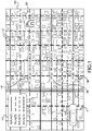
- FIG. 1 illustrates a map 100, which may be displayed on a display screen (e .g., navigation system display screen, dedicated in-vehicle display screen, dashboard mounted display screen, heads-up display, mobile device display screen, etc.) according to certain exemplary embodiments.
- map 100 illustrates an image of an area surrounding a vehicle V.
- the map 100 also illustrates a current position of the vehicle V and an icon 108 indicating a destination.
- the map also illustrates a number of possible routes 102, 104, 106 from a current location of a vehicle to a destination 108 (e.g., a user's home).
- three routes are provided (102, 104, 106). It is noted however, that any suitable number of routes may be provided.
- Route (or "path") planning may be defined as the process of determining a route based on and expressed in terms of an abstract world model. Algorithms may be configured to optimize a specific parameter such as a generic path cost or path length and may be classified based on the particular world model used.
- the specific route planning may be based on any number of approaches, including a network or graph-based approach and a grid-based approach. For network-based route planning, sometimes referred to as route planning, finds the shortest path using a network or directed weighted graph as a world model. Such approaches may be useful when the solution set for a path planning algorithm must be chosen from a fixed set of predefined paths. Furthermore, with network based analysis, no paths outside of the initial fixed set can be considered.
- the most recognizable application for this kind of modeling is the selection of the "best" route in a network of roads.
- the basic model for this application treats road intersections as graph nodes and roads as graph edges. Edge weights may be assigned based on physical properties of the road such as distance or travel time.
- Network-based algorithms may use local optimization at each stage to reach a global optimum.
- One example utilizes Dijkstra's algorithm to compute a minimum total path cost from a source node to all other nodes in a non-negative edge weighted graph (a network) and assigns an identifier to the previous node in the shortest path to each vertex. This previous node value can be used to reconstruct the least cost path from any node back to the source.
- Dijkstra's algorithm can also be used to solve a directed graph shortest path problem. In the case in which a least cost path between two given vertices is required, one vertex is chosen as a source vertex and the algorithm terminates when the destination vertex is reached.
- Dijkstra's algorithm advantageously finds the shortest cost path from one point to another without any additional information about the graph or edge weights.
- Dijkstra's algorithm can be computationally inefficient because a global structure often exists that can be used to further optimize the searching algorithm.
- the minimum possible distance between any node and the destination node is the Euclidean distance between the two corresponding intersections.
- the A* (“A Star") algorithm uses this minimal heuristic measurement to improve path finding efficiency over Dijkstra's algorithm.
- the minimal heuristic is a simplified measure that is guaranteed to be less than or equal to the shortest graph distance between two given nodes. In most route planning algorithms the Euclidean distance may be used as minimal heuristic between two nodes because it is simple and easy to calculate.
- a minimal heuristic can be any function that meets the same criteria.
- the speed up is largely based on the quality of the heuristic; the better the minimum heuristic estimates the shortest graph distance, the larger the speedup over standard Dijkstra's algorithm.
- the A* algorithm uses two main strategies to increase efficiency.
- the A* algorithm uses the path distance from the source plus the given minimal heuristic measure to the destination to determine the search order of potential nodes. This strategy may be advantageous because this value represents the minimum possible path distance through the given node and also generally serves as a good estimation of total path length. Also, it uses the heuristic to prune the search tree of unnecessary branches by comparing the minimum possible path distance (again the path distance from the source plus the minimal heuristic) through the given node with previous computed path lengths.
- Network-based path planning is very useful when there exists a fixed set of paths to choose from. But for a general case with unstructured terrain and off road driving, a grid-based path planning technique may be more appropriate.
- Such algorithms represent the terrain as a discrete grid where each cell has a cost to move through.
- the least cost path in a gridded algorithm is the collection of cells such that the cost of moving from the center of a source cell to the center of a destination cell is minimized.
- Most grid-based path planning algorithms are related forms of the network-based algorithms, discussed above. To apply the network based algorithm to the raster data, a node/link representation may be used.
- the gridded data set forms a lattice in which each cell center represents a node with edges to its direct neighbors. Edge weights are assigned based on cost values of the two adjacent cells and the travel direction as well as other potential directional weights.
- GIS implementations can apply network algorithms such as A* and Dijkstra's Algorithm to solve path planning algorithms on the raster datasets.
- Route planning that utilizes a grid-based path planning algorithms may include an accumulated cost surface method.
- This exemplary method may use a cost layer that represents the relative difficulty of moving through a particular cell and then finds the path from a source cell to a destination cell (through cell centers) that has the least total cost. This is accomplished by creating a layer, called an accumulated cost surface, in which each cell is accumulated cost of the shortest path from that cell to the given source cell. Simultaneously, a layer (“backtrack layer”) is generated in which each cell represents the direction to the previous cell in the shortest path. Using this backtrack layer a least cost path can be traced from any cell back to the source cell.
- the accumulated surface stores the list of shortest distance values while the backtrack layer stores a value that represents the next neighbor along the least cost path. Since each cell location is only connected to its neighbors in the node/link representation, the backtrack value can be represented as an integer in the range of one to eight that specifies the specific neighbor cell along the least cost path.
- Data for each of the routes may be provided from a plurality of different navigational data sources.
- data may be communicated/received from satellite data 202, a vehicle data source (e.g., Google Maps, GPS, etc.) 204, and/or a probe car 206.
- Satellite data 202 may comprise image data and/or other navigation, GPS and map-related data. Satellite data may be based on one or more formats or platforms including GeoEye, DigitalGlobe, Spotlmage, RapidEye, Earth Resource Observation Satellites (EROS), Meteosat, and others.
- the map image data illustrated in FIG. 1 may be provided via satellite or aerial photography.
- tangibly embodied software and algorithms may be used to process and store aerial remote sensing data.
- aerial LIDAR data may be used for vehicle path planning.
- Aerial LIDAR is especially suited to path planning for several reasons.
- aerial LIDAR data can have a very high spatial resolution and vertical accuracy.
- important path planning features such potential obstacles, terrain slope, and terrain roughness can be derived from aerial LIDAR data.
- a vehicle LIDAR system is configured to function on the principal of laser ranging.
- a laser pulse may be sent at a specific (sensor relative) angle and the time of flight is measured and used to determine a distance.
- attitude and positional data are captured using a high accuracy GPS system (e.g., Differential or DGPS; see FIG. 2 ).
- the LIDAR scanner and the position and orientation system are preferably time synchronized.
- the range and angle data capture by the LIDAR system are then coordinated with the position and orientation measurements to geo-reference the laser returns.
- direct measurements of position and orientation are used in geo-referencing, instead of correlating data to known reference points.
- the map data may not be entirely accurate as the satellite image may be outdated and may not reflect a current map layout.
- the quality of the data may be fairly low and not accurate for determining if the vehicle can drive autonomously.
- data may be provided from a vehicle data source/database (e.g., Google Maps, GPS, etc.) 204.
- a vehicle data source/database e.g., Google Maps, GPS, etc.
- a subset of the different routes that populates the area between the vehicle's current location and destination may have been stored (e.g., photographed, scanned, etc.). Again, this data may become outdated, depending on the physical changes occurring over time in the area.
- probe cars 206 may be provided by probe cars 206, which have travelled along various routes that comprise possible routes between the vehicle's current location and destination within the last hour, and this data was subsequently uploaded to the server for autonomous driving usage.
- the data from each data source may be factored into the calculation of the PA value to provide an accurate picture of which routes and their constituent segments are more optimal for driving autonomously.
- the system uses the data obtained from the data sources illustrated in FIG. 2 to generate the map 100 illustrated in FIG. 1 .
- the data from the individual data sources is aggregated to obtain a most accurate depiction of the area surrounding the vehicle.
- the data aggregation is preferably performed on a server (e.g., incorporated into vehicle, remote server at vehicle manufacturer, etc.) using a dedicated application.
- the application is designed such that it will query all drivable roadways (e.g., in United States, other countries, etc.) for necessary data used for calculating a vehicle's position and orientation.
- Such data includes, but is not limited to, LIDAR, radar, acoustic/ultrasonic, GPS, Car-to-x, street-view, aerial and space photography.
- the data for calculating position and orientation will either exist or not exist for the different segments along the variably calculated routes that exist between a current location of the vehicle and a destination.
- Existing data from the above sources may be summed for the different segments that comprise a route between the current location of the vehicle and the destination.
- the system determines a number of possible routes (102, 104, 106) from the starting point/current location of the vehicle V to the destination 108.
- Each of the possible routes 102, 104, 106 in the example is displayed on the map 100 as shown. Under one exemplary embodiment, the route with the highest PA value be displayed first, followed by N items in descending order of PA.
- Map 100 may be separated into a plurality of route segments 112, illustrated as a grid on map 100.
- a route segment is not necessarily a specific length of roadway, but rather a general term referring to any portion of roadway that can be driven on by a vehicle.
- the system determines and assigns, as detailed further below, a PA value to each of the route segments.
- Each route segment 112 is provided with a different line format (e.g., full line, dashed line, etc.).
- the map 100 may also include a legend 110 identifying the PA value associated with each line format.
- each potential route includes an augmented section (depicted by respective informational icons or windows in 102, 104, and 106) with information describing the route.
- the augmented section may indicate the distance the vehicle will travel along the route and the PA value for the route.
- the segmented section may include further information as necessary, such as the estimated amount of time the vehicle will travel along the route. The specific manner in which the map 100 and its contents are generated is discussed in further detail below.
- the exemplary embodiments disclosed herein are configured to address the need for a driver of a semi-autonomous vehicle to have optional routes that vary in the amount of autonomous driving offered.
- One advantage in offering such options is that the driver can choose to drive a route that affords 95% or 5% autonomous driving, depending on the current needs of the driver. Additionally, it provides the driver the opportunity to trade off the length (distance and/or time) of the route against the PA value.
- the system may employ a plurality of different techniques for calculating a route, which are described below.
- One technique assigns a continuous (c-method) value to the constituent segments of roadways in a given area and one that assigns a binary (b-method) value to the constituent segments of roadways in a given area.
- a c-method may be implemented after aggregating data from the different data sources illustrated in FIG. 2 .
- the system can assign a PA value to the different route segments populating the entire section that contains the current location of the vehicle V and the destination 108, as illustrated in FIG. 1 .
- the PA value for each route segment is calculated after data aggregation of the variable data sources used for calculating vehicle position and orientation.
- a particular route segment may have data for its entire length or a portion of its entire length. If data exists for the entire length of the segment, then the particular segment has a PA value of 100%. If data exists for only a portion of the route's length, then that particular segment has a PA value of N%.
- all N% values may be summed across all segments of a particular route to calculate a PA value for that route.
- the PA values of the route segments by themselves in FIG. 1 range from 25% to 100%.
- a route segment with a PA of 25% can only be driven on in autonomous mode for 25% of the length of the roadway and a segment with a PA of 100% can be driven on in autonomous mode for 100% of its length. This information is now available for a routing strategy algorithm to be used in calculating a route between the current position and destination.
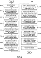
- an exemplary method 300 is disclosed, utilizing any of the configurations disclosed above.
- a user may input a destination location 302 using a user device, such as a smart phone, computer, vehicle infotainment system, etc.
- a first route is processed in the system 304, which minimizes length (e.g., distance and/or time) between a starting position and the destination location input by the user.
- the route is calculated using a routing algorithm, which may include any number of software and/or hardware components.
- a computer program product in accordance with one embodiment comprises a tangible computer usable medium (e.g., standard RAM, an optical disc, a USB drive, or the like) having computer-readable program code embodied therein, wherein the computer-readable program code is adapted to be executed by a processor (working in connection with an operating system) to implement one or more functions and methods as described herein.
- the program code may be implemented in any desired language, and may be implemented as machine code, assembly code, byte code, interpretable source code or the like (e.g., via C, C++, C#, Java, Actionscript, Objective-C, Javascript, CSS, XML, etc.). Routing algorithms may be further coupled to routing databases or libraries, such as DGLib, Graphserver, pgRouting, Libosmscout, Spacialite and GraphHopper, among others.
- PA values for the calculated route are then assigned 306 to individual route segments that comprise the overall route.
- the PA values for each segment are then weighted 308 according to each segment's length and then summed across all segments to get an overall PA value for the calculated route.
- the routing algorithm 300 may calculate a second route 310 that provides the second best minimization of distance and/or time between the starting position and the destination location.
- PA values for the calculated route are again assigned 312 to the individual segments that comprise the route.
- the PA values for each segment are then weighted 312 according to each segment's length and then summed across all segments to get an overall PA value for this second route.
- PA values for routes one and two are then compared 314, and, if the PA value for the first route is greater than the second route, then the second route is discarded 318 as a route option. Alternatively, if the PA value for the first route is less than the second route, then the second route is kept as an option.
- n-best list is created 320 wherein distance between start position and destination has been minimized and the PA values for the calculated routes have been maximized.
- the results of the n-best list are then depicted in graphical format and may be displayed on an in-vehicle display screen or mobile device display screen in the format illustrated in FIG. 1 or presented in a text format (e.g., on a user's mobile device) for selection (322).
- the selected route is displayed to the user and the vehicle then navigates 324 along the selected route in variable modes (e.g., autonomous and manual modes).
- variable modes e.g., autonomous and manual modes.
- the vehicle's human-machine interface HMI
- the vehicle's HMI indicates to the driver that autonomous mode can be engaged 328. The process is continued until the destination is reached 330.
- FIG. 4 an exemplary embodiment for a b-method is illustrated.
- the process in FIG. 4 is similar to the c-method of FIG. 3 , except that the constituent segments of the route are not assigned a probabilistic value (e.g., .001 ⁇ p ⁇ 1.00), but instead are assigned binary values (e.g., 1 for "yes” can be driven autonomously and 0 for "no" can't be driven autonomously).
- operations 402-424 and 430 are equivalent to operations 302-324 and 330 in FIG. 3 and, for purposes of brevity, the details of each will not be discussed.
- the operations in the b-method that differ from the operations in the c-method are operations (426) and (428).
- the vehicle's HMI upon approaching a segment on the route wherein the PA value is 0, the vehicle's HMI will warn the driver ahead of time 426 to take manual control of the vehicle.
- the vehicle's HMI upon approaching a segment on the route wherein the PA value is 1, the vehicle's HMI indicates to the driver that autonomous mode can be engaged.
- map 500 is illustrated, which may be generated using the b-method technique described above.
- route segments 504 are identified by either a full line, indicating a PA binary value of 1, or a dashed line, indicating a PA binary value of 0.
- Map 500 also includes a legend 502, identifying the binary PA values. It can be appreciated by those skilled in the art that the c-method provides greater granularity in the processing and presentation of autonomous-based navigation, while the b-method provides greater simplicity. Additionally, the b-method processing may be based on a specific PA value, and/or a PA value meeting or exceeding one or more thresholds.
- a "0" b-method value may be assigned. Conversely, if the PA value meets or exceeds a predetermined threshold value, a "1" b-method value may be assigned.
- the system disclosed herein may calculate n-number of routes between a starting location and a destination location wherein each successively calculated route might be a slightly longer, but the PA value of the route is increased.
- the driver may advantageously choose from the list of alternatives presented in an "n-best" list.
- there might be a desire by the user to reach a destination in the shortest amount of time and/or distance and may select the appropriate route.
- the present disclosure provides techniques for maximizing the PA while minimizing the distance and/or time travelled.
- the decision of route selection for autonomous driving may be left up to the individual user to decide by making a selection from a n-best list.
- the system may be configured to make a selection for the user based on a predefined balancing of PA value and time/distance travelled.
- the PA value is contrasted with optimal travel time and/or distance across n-options (e.g., n-best list) for purposes of making a decision about which route to choose to drive.
- AL iA represents the total length of roadway along a route that can be driven autonomously and L TOT represents the total length of roadway.
- FIG. 6 illustrates a use case 600 under one exemplary embodiment, where a driver may enter a destination into a processing device, such as a mobile terminal 602 (e.g., smart phone).
- a processing device such as a mobile terminal 602 (e.g., smart phone).
- the present disclosure is not limited to mobile terminals, may include other suitable devices, such as a desktop computer, laptop, or an in-vehicle navigation system.
- the ADRPA algorithm may then calculate an n-best list of possible routes between a specified start location and destination.
- the route planning process may also incorporate stopovers or waypoints such as stopping at a gas station on the way to a destination.
- the returned route options are then displayed to the user on a map screen that is augmented with information about each route (604).
- the routes may be prioritized according to one or more characteristics, including routes that (i) afford the greatest amount of autonomous driving, (ii) provides for the least amount of travel time, and/or (iii) provide the shortest travel distance.
- routes that (i) afford the greatest amount of autonomous driving, (ii) provides for the least amount of travel time, and/or (iii) provide the shortest travel distance.
- n-best list may be shown in many different ways. For exmple, the results could be shown simply in a list of text, showing a larger number (e.g., ten) of options prioritized around PA.
- the results could be depicted in graphic or iconic format, using color, shading, texture, type, and design to indicate the various decision parameters of PA, time, and distance.
- the entire application could also be incorporated into a voice user interface, such the all the user operations and application events are performed via speech input and audio output.
- the user in our example can simply place the mobile device near the navigation system to send the selected destination to the vehicle's navigation system via near field communication (NFC) (606) or other suitable wireless communication protocols such as Wi-Fi or Bluetooth.
- NFC near field communication
- Wi-Fi wireless fidelity
- Bluetooth wireless fidelity
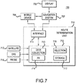
- FIG. 7 illustrates an automatic driving route planning system 700 according to another exemplary embodiment.
- the system 700 is configured to perform the processes and methods described above.
- the system includes a route determination unit 710.
- the route determination unit 710 includes a processing unit 712 configured to perform numerous tasks in accordance with the automatic driving route planning described above.
- Processing unit 712 may comprise a single dedicated hardware component, or multiple dedicated hardware components. Alternatively, the processing unit 712 may be incorporated into an integrated vehicle computing system or a vehicle navigation system.
- processing unit 712 may be configured to receive inputs, both from user input and database/data source input, process the received inputs, and provides output and processing results to the user.
- processing unit 712 may include a data collection device 713 configured to receive and aggregate data from various sources, a PA component 714 configured to assign a percent autonomous value, an optimization/selection component 715 configured to minimize a distance between a start position and a destination position and configured to maximize the percent autonomous value assigned, and a data storage device 717 configured to store data input as well as historically driving/location/destination data.
- the data collection unit 713 may be configured to receive data from a plurality of data sources including, but not limited to, a satellite source 722, a vehicle data source 724, and/or a probe car 726.
- Route determination unit 710 may also be configured to interact with a mobile device (e.g., smartphone, laptop computer, etc.) 704 and a navigation system 702 of a vehicle (V).
- the system 700 may include an interface 711 (e.g., HMI) configured to receive and transmit data to and from the mobile device 704.
- a user may input a destination using the mobile device 704.
- the mobile device 704 is connectable to the interface 711 either by a direct connection (e.g., a docking station within a vehicle) or through a wireless connection.
- Data from the mobile device 704 may be transferred through the interface 711 for processing.
- the system may provide data/results with respect to potential driving routes to the mobile device 704.
- the results may be presented in text format or as an image (e.g., map) to be displayed on a display screen of the mobile device.
- the user may then operate the mobile device 704 to select a desired route, whereby the selection is sent back through the interface 711.
- Interface 711 may also be configured to receive and transmit data to and from the navigation system 702. Once a user has selected a desired route, the data corresponding to the selected route is sent to the navigation system 702.
- the navigation system 702 displays the selected route on an in-vehicle display screen. Additionally, in the autonomous driving mode, navigation system 702 may navigate the vehicle according to the selected route. Additionally, a user may interact with the system 700 directly through the navigation system 702 and vehicle mounted controls. Specifically, the user may enter the destination input directly through the vehicle mounted controls of the navigation system 702. Driving route options may then be displayed on the in-vehicle display 706 and the user may select a desired option using the vehicle mounted controls of the navigation system 702.
- the system 700 described above may be incorporated into a vehicle. That is, the route determination unit 710 and its components may be incorporated into a vehicle. Alternatively, the route determination unit may operate as a remote system (e.g., remote from the user's vehicle). The mobile device 704 and the navigation system 702 may interact with the route determination unit 710 via wired or wireless connection.
- a computer-implemented method may be employed for performing at least certain operations in the present disclosure. Such a method may be implemented, for example, by operating a computer, as embodied by a digital data processing apparatus, to execute a sequence of machine-readable instructions. These instructions may reside in various types of storage media.
- this aspect of the present disclosure covers a programmed product, including storage media (or a storage device) tangibly embodying a program of machine-readable instructions executable by a digital data processor.
- the storage media may include, for example, a RAM contained within the CPU, as represented by the fast-access storage for example.
- the instructions may be contained in another storage media, such as a magnetic data storage diskette, compact disc, or other removable storage media/device, directly or indirectly accessible by the CPU.
- U.S. Patent Application Publication No. 2002/0120396 discloses the use of historical data to allow the user to plan and optimize a route according to the user's particular preferences.
- a user may enter information into the system regarding areas the user would like to avoid. For example, the user may wish to avoid areas with significantly higher crime rates than the average crime rates for the region of travel. Subsequently, a user may set a route from their current start location to a destination location. If, along the calculated route, there is a traversal across an area with high crime rates, the user will then be informed and offered an alternative route. The user can again make the decision about which is the optimum route of travel.
- U.S. Patent No. 7,865,298 allows the driver of an electric vehicle to optimize routes for battery performance improvements. That is, the system will factor in weather conditions, traffic flow, and terrain for purposes of predicting charge depletion time, range, travel time, etc. The driver can then be informed about the impact of these variables and make a choice of an optimum route.
- U.S. Patent Application Publication No. 2008/0183381 discloses a navigation system that is capable of making a route search by specifying the propriety of use of individual special roads (e.g., toll roads) to the destination.
- the propriety of use of the special roads may be individually selected and the route is then researched based on the selected propriety of use for the special road.
- the conventional art is focused specifically on defining systems and methods for optimizing route plans with non-autonomous vehicles, meaning that routes are ultimately selected only through the physical decisions and actions of the user after taking into account historical data, weather conditions, traffic density, and a host of other variables that can impact travel time and/or distance.
- the conventional art does not provide a system and method for planning and optimizing routes for semi-autonomous and/or fully autonomous vehicles, which limit and even eliminate the need for user interaction.
- the conventional art does not factor in variables to calculate a percentage of a route that can be driven autonomously with a vehicle that has the requisite technology to do so.
Description
- The present disclosure relates to vehicle navigation systems and more specifically to an automatic driving route planning application running on navigation equipment within a vehicle or running on a mobile device.
- Today's navigation applications on mobile devices such as smart phones, desktop computers, or in-vehicle navigation systems assist users in devising optimum travel routes to destinations, help users understand vehicle orientation and direction of travel, illustrate various places of interest, and inform the driver about driving conditions on a road network (e.g., traffic density, weather, accidents, construction, etc.).
- Some recent advances within the navigation systems include algorithms and interfaces that perform optimization of route planning according to carbon footprint (e.g., eco-driving route planning), battery efficiency (e.g., electric vehicle route planning), comfort (e.g., scenic route planning), and safety (e.g., avoid high crime area route planning). Others have proposed various systems and methods for determining the optimum route to a destination. However, such conventional systems are focused specifically on defining systems and methods for optimizing route plans with non-autonomous vehicles, meaning that routes are ultimately selected only through the physical decisions and actions of the user after taking into account historical data, weather conditions, traffic density, and a host of other variables that can impact travel time and/or distance. The conventional art, however, does not provide a system and method for planning and optimizing routes for semi-autonomous and/or fully autonomous vehicles, which limit and even eliminate the need for user interaction. Moreover, the conventional art does not factor in variables to calculate a percentage of a route that can be driven autonomously with a vehicle that has the requisite technology to do so.
-
US2012/0179361 A1 describes a system and method, in which a plurality of routes is calculated and displayed with map data comprising information relating to the length value for each of the routes.EP 1 308 812 A2 - In view of the foregoing and other exemplary problems, drawbacks, and disadvantages of the conventional methods and structures, an exemplary feature of the present disclosure is to provide a system and method suitable for autonomously and/or semi-autonomously planning and optimizing a route to a specific destination desired by a user.
- A system and method according to the invention are defined in
claims - Under certain exemplary embodiments, a system and method is disclosed for planning and calculating routes for a vehicle that has the requisite technology to drive autonomously, without human input or intervention, for the entire length (e.g., fully autonomous vehicle) or a portion (semi-autonomous vehicle) of a planned route. To this end, a method and system tangibly embodied in a computer software application deployed on a processing device, such as a smartphone, tablet, laptop, desktop computer, or in-vehicle navigation system, is disclosed for planning and calculating a route for the user of a vehicle that has a certain degree of automatic driving capability (e.g., semi-autonomous vehicle).
- Under at least one exemplary embodiment, a system is disclosed for processing and optimizing a route to a specific destination via a vehicle that has the capability to drive autonomously. The system may include a data collection device configured to aggregate data from various sources to thereby position and orient the vehicle, a component configured to assign a percent autonomous value to different route segments, a selection component configured to minimize a distance between a start position and a destination position and configured to maximize the percent autonomous value assigned, and a display adapted to display at least one route.
- Under at least one exemplary embodiment, a method is disclosed for planning and optimizing a route to a specific destination via a vehicle that has the capability to drive autonomously. The method may include the operations of aggregating data from various sources to thereby position and orient the vehicle, assigning a percent autonomous value to different route segments, determining an optimal route by minimizing a distance between a start position and a destination position and maximizing the percent autonomous value assigned, and displaying the optimal route.
- Under at least one exemplary embodiment, a system is disclosed that includes a route device configured to calculate a plurality of routes to a destination. One or more of the routes may comprise a plurality of route segments. The system may include a data collection device configured to aggregate route planning data from a plurality of sources, a calculating device configured to calculate a percent autonomous value for each of the plurality of route segments of each of the plurality of routes, and a route optimizing component configured to determine an optimal route to the destination based on the length of each route and the percent autonomous value for each route segment.
- Under yet at least one exemplary embodiment, a method of navigating a vehicle is disclosed, wherein the method comprises the operations of entering a destination, generating a plurality of routes to a destination, the routes each having a length, assigning a percent autonomous value to each of the plurality of routes, and presenting each of the plurality of routes to a user, wherein each of the routes indicating the percent autonomous value and the length of the route, selecting one of the plurality of routes and operating the vehicle along the selected route.
- Further scope of applicability of the present disclosure will become apparent from the detailed description given hereinafter. However, it should be understood that the detailed description and specific examples, while indicating preferred embodiments, are given by way of illustration only.
- The present disclosure will become more fully understood from the detailed description given herein below and the accompanying drawings which are given by way of illustration only, and thus, do not limit the present disclosure, and wherein:
-
FIG. 1 illustrates an exemplary driving route map for a vehicle generated and displayed according to one embodiment, where a plurality of navigational routes are processed, evaluated and presented according to an autonomous driving value; -
FIG. 2 illustrates exemplary data sources for a vehicle, where the data sources include satellite, vehicle data source and/or a probe car for use with navigation under certain exemplary embodiments; -
FIG. 3 illustrates an exemplary embodiment for determining and processing percent autonomous (PA) values for route navigation, where the PA values are derived from a continuous (c-method) value to constituent segments of roadways in a given area; -
FIG. 4 illustrates an exemplary embodiment for determining and processing percent autonomous (PA) values for route and route segment navigation where the PA values are derived from a binary (b-method) value to constituent segments of roadways in a given area; -
FIG. 5 illustrates an exemplary driving route map generated by the configuration illustrated inFIGs. 3 and/or 4 where a plurality of navigational routes are processed, evaluated and presented according to an autonomous driving value; -
FIG. 6 illustrates an exemplary embodiment for processing and communicating routes to a user where a driver may enter a destination into a processing device, and a navigational algorithm may then calculate an n-best list of possible routes between a specified start location and destination.; and -
FIG. 7 illustrates a block diagram of a driving route planning system under another exemplary embodiment, where a determination unit performs navigational processing to assign a percent autonomous value and minimize a distance between a start position and a destination position and further configured to maximize the percent autonomous value assigned. - The figures and descriptions provided herein may have been simplified to illustrate aspects that are relevant for a clear understanding of the herein described devices, systems, and methods, while eliminating, for the purpose of clarity, other aspects that may be found in typical devices, systems, and methods. Those of ordinary skill may recognize that other elements and/or operations may be desirable and/or necessary to implement the devices, systems, and methods described herein. Because such elements and operations are well known in the art, and because they do not facilitate a better understanding of the present disclosure, a discussion of such elements and operations may not be provided herein. However, the present disclosure is deemed to inherently include all such elements, variations, and modifications to the described aspects that would be known to those of ordinary skill in the art.
- Autonomous vehicles (also known as driverless cars, self-driving cars or robot cars) are an autonomous vehicle capable of fulfilling the human transportation capabilities of a traditional car. As an autonomous vehicle, it is capable of sensing its environment and navigating without human input. Autonomous vehicles may be equipped with a high precision GPS navigation system and several laser scanners which it uses to detect obstacles. Autonomous vehicles may also be configured to sense their surroundings using technologies such as radar, Light Detection and Ranging (LIDAR), GPS, and computer vision. Advanced control systems interpret sensory information to identify appropriate navigation paths, as well as obstacles and relevant signage. Some autonomous vehicles update their maps based on sensory input, allowing the vehicles to keep track of their position even when conditions change or when they enter uncharted environments. Semi-autonomous (or quasi-autonomous) vehicles are vehicles that are capable of switching between an autonomous mode and a driver-controlled mode, and/or vehicles that are configured with autonomous driving features but require some driver input.
- Navigation systems, and particularly automotive navigation system, are typically embodied as a GPS navigation device used to acquire position data to locate the user on a road in a unit's map database. Using the road database, the unit can give directions to other locations along roads also in its database. Deduced reckoning (or "dead reckoning") that uses distance data from sensors attached to the drivetrain, a gyroscope and an accelerometer can be configured for greater reliability, as GPS signal loss and/or multipath can occur due to urban canyons or tunnels.
- While conventional navigation systems are configured to provide navigational data and guidance based on factors such as distance traveled, traffic, highway travel, etc., few, if any, navigation systems account for autonomous and/or semi-autonomous driving factors. As autonomous and semi-autonomous vehicles become more commonplace in commercial and/or consumer use, navigation systems will need to adapt so that navigational data and guidance includes autonomous driving factors.
- An automatic driving route planning application (ADRPA) is an one important component for semi-autonomous vehicles, and may fall into one of at least two types of autonomic driving capability categories: a first type is referred to as a Destination Not Set (DNS) and a second type can be called a Destination Set (DS). Certain DNS systems may be configured to provide a combination of adaptive cruise control (ACC) and Active Lane Guidance (ALG). The combination of these two technologies essentially means the vehicle is automatically controlling both the longitudinal and lateral movements of the vehicle, albeit in very limited driving contexts. In this configuration, the vehicle is performing automated driving, but is not performing automated navigation. That is, the vehicle has no idea where it is going, what the destination is, or even what the next upcoming maneuver is.
- The DS category combines autonomous driving and navigation. The combination of these two technologies means that not only is the vehicle automatically controlling both the longitudinal and lateral movements of the vehicle, but it is also making decisions about upcoming maneuvers that are required to reach a destination. This type of vehicle, therefore, is performing automatic driving and navigation. Thus, the DS category of semi-autonomous vehicles, according to certain exemplary embodiments disclosed herein, is a focus of the various systems and methods for planning and calculating routes. Planning of a route for a vehicle that has some degree of autonomous driving capability may be advantageous, particularly where a destination may be known, along with alternative routes to the destination, and each alternative route affords different amounts of autonomous driving.
- According to certain exemplary embodiments disclosed herein, systems and methods are configured to process, plan and optimize a route to one or more destinations using a semi-autonomous or fully autonomous vehicle (e.g., an automatic driving route planning application or "ADRPA"). Route optimization for typical navigation systems are mostly concerned with analyzing parameters of travel time and/or distance, and reducing one and/or he other. In other configurations, navigation systems may be optimized according to parameters set by a user, such as the avoidance to toll roads, traveling along a scenic route, etc. In certain exemplary embodiments disclosed herein, a navigation system may be configured to process any and all of the conventional navigation parameters, and further process parameters basing on an autonomous value for given routes and/or route segments (e.g., a percentage of a route that can be driven autonomously). As will be seen in the disclosure herein, the autonomous value is referred to as "Percent Autonomous" (PA). It should be appreciated by those skilled in the art, that, while the autonomous value is depicted as a percentage, various other values, ratios, and numerical relationships are contemplated in this disclosure.
- The PA value is advantageous as a navigation optimization parameter, particularly for a driver of a semi-autonomous vehicle because, as a practical matter, it is not likely that all possible routes between two locations are capable of being driven 100% autonomously. During operation, a semi-autonomous vehicle may not have data pertaining to one or more segments of a navigational route. This lack of data may be the result of: (1) the data having never been collected and stored into a database for subsequent use by automated vehicles; (2) the data that was collected was not of sufficient quality for subsequent use by automated vehicles; and/or (3) the data that was collected for subsequent use by automated vehicles is no longer useful because the physical characteristics of the navigational roadway on which the data is based are no longer visible, or obscured by dynamic environmental elements (e .g. , snow, rain or ice covers the roadway). It also might be the case that the data was collected and is generally suitable for navigation, but restrictions on the route (e.g., private property/road, school zone) prevent it from being utilized.
- Under certain exemplary embodiments, a navigation system may be configured to process a variety of data for purposes of route planning and optimization for a semi-autonomous vehicle. This data can come from a variety of sources (e.g., aerial, satellite, and terrestrial laser scans and photography, etc.). Such data may be used for automatic driving for positioning, orienting, and navigating the vehicle and to provide an accurate representation of the surrounding environment with respect to roads, buildings, structures, mountains, etc. Furthermore this data may be processed for route planning and optimization. For example, it is possible that there are multiple routes available from a starting location to a specific destination location.
-
FIG. 1 illustrates amap 100, which may be displayed on a display screen (e .g., navigation system display screen, dedicated in-vehicle display screen, dashboard mounted display screen, heads-up display, mobile device display screen, etc.) according to certain exemplary embodiments. In the example illustrated inFIG. 1 ,map 100 illustrates an image of an area surrounding a vehicle V. Themap 100 also illustrates a current position of the vehicle V and anicon 108 indicating a destination. The map also illustrates a number ofpossible routes FIG. 1 , three routes are provided (102, 104, 106). It is noted however, that any suitable number of routes may be provided. - Route (or "path") planning may be defined as the process of determining a route based on and expressed in terms of an abstract world model. Algorithms may be configured to optimize a specific parameter such as a generic path cost or path length and may be classified based on the particular world model used. The specific route planning may be based on any number of approaches, including a network or graph-based approach and a grid-based approach. For network-based route planning, sometimes referred to as route planning, finds the shortest path using a network or directed weighted graph as a world model. Such approaches may be useful when the solution set for a path planning algorithm must be chosen from a fixed set of predefined paths. Furthermore, with network based analysis, no paths outside of the initial fixed set can be considered. The most recognizable application for this kind of modeling is the selection of the "best" route in a network of roads. The basic model for this application treats road intersections as graph nodes and roads as graph edges. Edge weights may be assigned based on physical properties of the road such as distance or travel time.
- Network-based algorithms may use local optimization at each stage to reach a global optimum. One example utilizes Dijkstra's algorithm to compute a minimum total path cost from a source node to all other nodes in a non-negative edge weighted graph (a network) and assigns an identifier to the previous node in the shortest path to each vertex. This previous node value can be used to reconstruct the least cost path from any node back to the source. Dijkstra's algorithm can also be used to solve a directed graph shortest path problem. In the case in which a least cost path between two given vertices is required, one vertex is chosen as a source vertex and the algorithm terminates when the destination vertex is reached. Dijkstra's algorithm advantageously finds the shortest cost path from one point to another without any additional information about the graph or edge weights. However for real world route planning, Dijkstra's algorithm can be computationally inefficient because a global structure often exists that can be used to further optimize the searching algorithm.
- Specifically, there may exist a simple function that gives a lower bound estimation of the graph distance between a given node and the destination node. For example, in a road network where an edge weights represent road lengths and nodes represent road intersections, the minimum possible distance between any node and the destination node is the Euclidean distance between the two corresponding intersections. The A* ("A Star") algorithm uses this minimal heuristic measurement to improve path finding efficiency over Dijkstra's algorithm. The minimal heuristic is a simplified measure that is guaranteed to be less than or equal to the shortest graph distance between two given nodes. In most route planning algorithms the Euclidean distance may be used as minimal heuristic between two nodes because it is simple and easy to calculate. However, a minimal heuristic can be any function that meets the same criteria. The speed up is largely based on the quality of the heuristic; the better the minimum heuristic estimates the shortest graph distance, the larger the speedup over standard Dijkstra's algorithm.
- The A* algorithm uses two main strategies to increase efficiency. First, the A* algorithm uses the path distance from the source plus the given minimal heuristic measure to the destination to determine the search order of potential nodes. This strategy may be advantageous because this value represents the minimum possible path distance through the given node and also generally serves as a good estimation of total path length. Also, it uses the heuristic to prune the search tree of unnecessary branches by comparing the minimum possible path distance (again the path distance from the source plus the minimal heuristic) through the given node with previous computed path lengths.
- Network-based path planning is very useful when there exists a fixed set of paths to choose from. But for a general case with unstructured terrain and off road driving, a grid-based path planning technique may be more appropriate. Such algorithms represent the terrain as a discrete grid where each cell has a cost to move through. The least cost path in a gridded algorithm is the collection of cells such that the cost of moving from the center of a source cell to the center of a destination cell is minimized. Most grid-based path planning algorithms are related forms of the network-based algorithms, discussed above. To apply the network based algorithm to the raster data, a node/link representation may be used. In this representation, the gridded data set forms a lattice in which each cell center represents a node with edges to its direct neighbors. Edge weights are assigned based on cost values of the two adjacent cells and the travel direction as well as other potential directional weights. Using this method GIS implementations can apply network algorithms such as A* and Dijkstra's Algorithm to solve path planning algorithms on the raster datasets.
- Route planning that utilizes a grid-based path planning algorithms may include an accumulated cost surface method. This exemplary method may use a cost layer that represents the relative difficulty of moving through a particular cell and then finds the path from a source cell to a destination cell (through cell centers) that has the least total cost. This is accomplished by creating a layer, called an accumulated cost surface, in which each cell is accumulated cost of the shortest path from that cell to the given source cell. Simultaneously, a layer ("backtrack layer") is generated in which each cell represents the direction to the previous cell in the shortest path. Using this backtrack layer a least cost path can be traced from any cell back to the source cell. The accumulated surface stores the list of shortest distance values while the backtrack layer stores a value that represents the next neighbor along the least cost path. Since each cell location is only connected to its neighbors in the node/link representation, the backtrack value can be represented as an integer in the range of one to eight that specifies the specific neighbor cell along the least cost path.
- Data for each of the routes may be provided from a plurality of different navigational data sources. As can be seen from
FIG. 2 , an exemplary configuration is provided, where data may be communicated/received fromsatellite data 202, a vehicle data source (e.g., Google Maps, GPS, etc.) 204, and/or aprobe car 206.Satellite data 202 may comprise image data and/or other navigation, GPS and map-related data. Satellite data may be based on one or more formats or platforms including GeoEye, DigitalGlobe, Spotlmage, RapidEye, Earth Resource Observation Satellites (EROS), Meteosat, and others. - The map image data illustrated in
FIG. 1 may be provided via satellite or aerial photography. As will be discussed in greater detail below, tangibly embodied software and algorithms may be used to process and store aerial remote sensing data. In one exemplary embodiment, aerial LIDAR data may be used for vehicle path planning. Aerial LIDAR is especially suited to path planning for several reasons. First, aerial LIDAR data can have a very high spatial resolution and vertical accuracy. Furthermore, because aerial LIDAR records the distance to physical objects, important path planning features such potential obstacles, terrain slope, and terrain roughness can be derived from aerial LIDAR data. - A vehicle LIDAR system is configured to function on the principal of laser ranging. A laser pulse may be sent at a specific (sensor relative) angle and the time of flight is measured and used to determine a distance. Simultaneously, attitude and positional data are captured using a high accuracy GPS system (e.g., Differential or DGPS; see
FIG. 2 ). The LIDAR scanner and the position and orientation system are preferably time synchronized. The range and angle data capture by the LIDAR system are then coordinated with the position and orientation measurements to geo-reference the laser returns. Under one exemplary embodiment, direct measurements of position and orientation are used in geo-referencing, instead of correlating data to known reference points. - In certain cases however, the map data may not be entirely accurate as the satellite image may be outdated and may not reflect a current map layout. Thus, the quality of the data may be fairly low and not accurate for determining if the vehicle can drive autonomously. In addition to the satellite imagery, data may be provided from a vehicle data source/database (e.g., Google Maps, GPS, etc.) 204. For example, a subset of the different routes that populates the area between the vehicle's current location and destination may have been stored (e.g., photographed, scanned, etc.). Again, this data may become outdated, depending on the physical changes occurring over time in the area. Lastly, data may be provided by
probe cars 206, which have travelled along various routes that comprise possible routes between the vehicle's current location and destination within the last hour, and this data was subsequently uploaded to the server for autonomous driving usage. The data from each data source may be factored into the calculation of the PA value to provide an accurate picture of which routes and their constituent segments are more optimal for driving autonomously. - Using the data obtained from the data sources illustrated in
FIG. 2 , the system generates themap 100 illustrated inFIG. 1 . Specifically, the data from the individual data sources is aggregated to obtain a most accurate depiction of the area surrounding the vehicle. The data aggregation is preferably performed on a server (e.g., incorporated into vehicle, remote server at vehicle manufacturer, etc.) using a dedicated application. The application is designed such that it will query all drivable roadways (e.g., in United States, other countries, etc.) for necessary data used for calculating a vehicle's position and orientation. Such data includes, but is not limited to, LIDAR, radar, acoustic/ultrasonic, GPS, Car-to-x, street-view, aerial and space photography. The data for calculating position and orientation will either exist or not exist for the different segments along the variably calculated routes that exist between a current location of the vehicle and a destination. Existing data from the above sources may be summed for the different segments that comprise a route between the current location of the vehicle and the destination. Based on the aggregated data, the system determines a number of possible routes (102, 104, 106) from the starting point/current location of the vehicle V to thedestination 108. Each of thepossible routes map 100 as shown. Under one exemplary embodiment, the route with the highest PA value be displayed first, followed by N items in descending order of PA. -
Map 100 may be separated into a plurality ofroute segments 112, illustrated as a grid onmap 100. For purposes of the present disclosure, a route segment is not necessarily a specific length of roadway, but rather a general term referring to any portion of roadway that can be driven on by a vehicle. Based on the aggregated data, the system determines and assigns, as detailed further below, a PA value to each of the route segments. Eachroute segment 112 is provided with a different line format (e.g., full line, dashed line, etc.). Themap 100 may also include alegend 110 identifying the PA value associated with each line format. Once the PA value for eachroute segment 112 is determined, an overall PA value for each entire route is calculated. As is illustrated inFIG. 1 , each potential route includes an augmented section (depicted by respective informational icons or windows in 102, 104, and 106) with information describing the route. As can be seen from the figure, the augmented section may indicate the distance the vehicle will travel along the route and the PA value for the route. The segmented section may include further information as necessary, such as the estimated amount of time the vehicle will travel along the route. The specific manner in which themap 100 and its contents are generated is discussed in further detail below. - As can be appreciated by those skilled in the art, the exemplary embodiments disclosed herein are configured to address the need for a driver of a semi-autonomous vehicle to have optional routes that vary in the amount of autonomous driving offered. One advantage in offering such options is that the driver can choose to drive a route that affords 95% or 5% autonomous driving, depending on the current needs of the driver. Additionally, it provides the driver the opportunity to trade off the length (distance and/or time) of the route against the PA value.
- In certain embodiments, the system may employ a plurality of different techniques for calculating a route, which are described below. One technique assigns a continuous (c-method) value to the constituent segments of roadways in a given area and one that assigns a binary (b-method) value to the constituent segments of roadways in a given area.
- A c-method may be implemented after aggregating data from the different data sources illustrated in
FIG. 2 . Once the data is aggregated from the different sources, the system can assign a PA value to the different route segments populating the entire section that contains the current location of the vehicle V and thedestination 108, as illustrated inFIG. 1 . The PA value for each route segment is calculated after data aggregation of the variable data sources used for calculating vehicle position and orientation. A particular route segment may have data for its entire length or a portion of its entire length. If data exists for the entire length of the segment, then the particular segment has a PA value of 100%. If data exists for only a portion of the route's length, then that particular segment has a PA value of N%. Lastly, all N% values may be summed across all segments of a particular route to calculate a PA value for that route. For illustration purposes only, the PA values of the route segments by themselves inFIG. 1 range from 25% to 100%. In general, a route segment with a PA of 25% can only be driven on in autonomous mode for 25% of the length of the roadway and a segment with a PA of 100% can be driven on in autonomous mode for 100% of its length. This information is now available for a routing strategy algorithm to be used in calculating a route between the current position and destination. - Turning now to
FIG. 3 , anexemplary method 300 is disclosed, utilizing any of the configurations disclosed above. Here, an exemplary c-method process is illustrated, where a user may input adestination location 302 using a user device, such as a smart phone, computer, vehicle infotainment system, etc. A first route is processed in thesystem 304, which minimizes length (e.g., distance and/or time) between a starting position and the destination location input by the user. According to certain exemplary embodiments, the route is calculated using a routing algorithm, which may include any number of software and/or hardware components. - In general, a computer program product in accordance with one embodiment comprises a tangible computer usable medium (e.g., standard RAM, an optical disc, a USB drive, or the like) having computer-readable program code embodied therein, wherein the computer-readable program code is adapted to be executed by a processor (working in connection with an operating system) to implement one or more functions and methods as described herein. In this regard, the program code may be implemented in any desired language, and may be implemented as machine code, assembly code, byte code, interpretable source code or the like (e.g., via C, C++, C#, Java, Actionscript, Objective-C, Javascript, CSS, XML, etc.). Routing algorithms may be further coupled to routing databases or libraries, such as DGLib, Graphserver, pgRouting, Libosmscout, Spacialite and GraphHopper, among others.
- PA values for the calculated route are then assigned 306 to individual route segments that comprise the overall route. The PA values for each segment are then weighted 308 according to each segment's length and then summed across all segments to get an overall PA value for the calculated route. The
routing algorithm 300 may calculate asecond route 310 that provides the second best minimization of distance and/or time between the starting position and the destination location. PA values for the calculated route are again assigned 312 to the individual segments that comprise the route. The PA values for each segment are then weighted 312 according to each segment's length and then summed across all segments to get an overall PA value for this second route. PA values for routes one and two are then compared 314, and, if the PA value for the first route is greater than the second route, then the second route is discarded 318 as a route option. Alternatively, if the PA value for the first route is less than the second route, then the second route is kept as an option. - The process of
FIG. 3 continues until an n-best list is created 320 wherein distance between start position and destination has been minimized and the PA values for the calculated routes have been maximized. The results of the n-best list are then depicted in graphical format and may be displayed on an in-vehicle display screen or mobile device display screen in the format illustrated inFIG. 1 or presented in a text format (e.g., on a user's mobile device) for selection (322). - Once a specific route is selected (e.g., by user selection), the selected route is displayed to the user and the vehicle then navigates 324 along the selected route in variable modes (e.g., autonomous and manual modes). Upon approaching a segment on the route wherein the PA value is below a certain threshold, the vehicle's human-machine interface (HMI) will warn the
driver 326 ahead of time to take manual control of the vehicle. Then, upon approaching a segment on the route where the PA value is above a certain threshold, the vehicle's HMI indicates to the driver that autonomous mode can be engaged 328. The process is continued until the destination is reached 330. - Turning to
FIG. 4 , an exemplary embodiment for a b-method is illustrated. The process inFIG. 4 is similar to the c-method ofFIG. 3 , except that the constituent segments of the route are not assigned a probabilistic value (e.g., .001 < p <1.00), but instead are assigned binary values (e.g., 1 for "yes" can be driven autonomously and 0 for "no" can't be driven autonomously). In this example, operations 402-424 and 430 are equivalent to operations 302-324 and 330 inFIG. 3 and, for purposes of brevity, the details of each will not be discussed. The operations in the b-method that differ from the operations in the c-method are operations (426) and (428). In the b-method process 400 ofFIG. 4 , upon approaching a segment on the route wherein the PA value is 0, the vehicle's HMI will warn the driver ahead oftime 426 to take manual control of the vehicle. Inoperation 428, upon approaching a segment on the route wherein the PA value is 1, the vehicle's HMI indicates to the driver that autonomous mode can be engaged. - Turning now to
FIG. 5 ,map 500 is illustrated, which may be generated using the b-method technique described above. Here,route segments 504 are identified by either a full line, indicating a PA binary value of 1, or a dashed line, indicating a PA binary value of 0.Map 500 also includes alegend 502, identifying the binary PA values. It can be appreciated by those skilled in the art that the c-method provides greater granularity in the processing and presentation of autonomous-based navigation, while the b-method provides greater simplicity. Additionally, the b-method processing may be based on a specific PA value, and/or a PA value meeting or exceeding one or more thresholds. In one example, if a PA value fails to meet or exceed a predetermined threshold value, a "0" b-method value may be assigned. Conversely, if the PA value meets or exceeds a predetermined threshold value, a "1" b-method value may be assigned. - Accordingly, the system disclosed herein may calculate n-number of routes between a starting location and a destination location wherein each successively calculated route might be a slightly longer, but the PA value of the route is increased. As such, the driver may advantageously choose from the list of alternatives presented in an "n-best" list. In one example, there might be a desire by the user to reach a destination in the shortest amount of time and/or distance, and may select the appropriate route. In another example, there may be a desire by the user to reach a destination while driving autonomously to get some work done or be entertained. The present disclosure provides techniques for maximizing the PA while minimizing the distance and/or time travelled. The decision of route selection for autonomous driving may be left up to the individual user to decide by making a selection from a n-best list. Alternatively, it is noted that the system may be configured to make a selection for the user based on a predefined balancing of PA value and time/distance travelled.
- In the disclosure discussed above, the PA value is contrasted with optimal travel time and/or distance across n-options (e.g., n-best list) for purposes of making a decision about which route to choose to drive. The PA value for the c-method can be determined by the following formula:

- The PA value for the b-method can be determined by the following formula:

-
FIG. 6 illustrates ause case 600 under one exemplary embodiment, where a driver may enter a destination into a processing device, such as a mobile terminal 602 (e.g., smart phone). As discussed above, the present disclosure is not limited to mobile terminals, may include other suitable devices, such as a desktop computer, laptop, or an in-vehicle navigation system. The ADRPA algorithm may then calculate an n-best list of possible routes between a specified start location and destination. The route planning process may also incorporate stopovers or waypoints such as stopping at a gas station on the way to a destination. The returned route options are then displayed to the user on a map screen that is augmented with information about each route (604). - In this example, the routes may be prioritized according to one or more characteristics, including routes that (i) afford the greatest amount of autonomous driving, (ii) provides for the least amount of travel time, and/or (iii) provide the shortest travel distance. One skilled in the art would appreciate that the results of an n-best list may be shown in many different ways. For exmple, the results could be shown simply in a list of text, showing a larger number (e.g., ten) of options prioritized around PA. The results could be depicted in graphic or iconic format, using color, shading, texture, type, and design to indicate the various decision parameters of PA, time, and distance. The entire application could also be incorporated into a voice user interface, such the all the user operations and application events are performed via speech input and audio output. After a route option is selected, the user in our example can simply place the mobile device near the navigation system to send the selected destination to the vehicle's navigation system via near field communication (NFC) (606) or other suitable wireless communication protocols such as Wi-Fi or Bluetooth. Lastly, the vehicle and its occupants travel to the selected destination via a combination of manual and
autonomous driving modes 608. -
FIG. 7 illustrates an automatic drivingroute planning system 700 according to another exemplary embodiment. Specifically, thesystem 700 is configured to perform the processes and methods described above. The system includes aroute determination unit 710. Theroute determination unit 710 includes aprocessing unit 712 configured to perform numerous tasks in accordance with the automatic driving route planning described above.Processing unit 712 may comprise a single dedicated hardware component, or multiple dedicated hardware components. Alternatively, theprocessing unit 712 may be incorporated into an integrated vehicle computing system or a vehicle navigation system. Specifically, processingunit 712 may be configured to receive inputs, both from user input and database/data source input, process the received inputs, and provides output and processing results to the user. To this end, processingunit 712 may include adata collection device 713 configured to receive and aggregate data from various sources, aPA component 714 configured to assign a percent autonomous value, an optimization/selection component 715 configured to minimize a distance between a start position and a destination position and configured to maximize the percent autonomous value assigned, and adata storage device 717 configured to store data input as well as historically driving/location/destination data. As detailed above, with respect toFIG. 2 , thedata collection unit 713 may be configured to receive data from a plurality of data sources including, but not limited to, a satellite source 722, a vehicle data source 724, and/or a probe car 726. -
Route determination unit 710 may also be configured to interact with a mobile device (e.g., smartphone, laptop computer, etc.) 704 and anavigation system 702 of a vehicle (V). To this end, thesystem 700 may include an interface 711 (e.g., HMI) configured to receive and transmit data to and from themobile device 704. As detailed above, a user may input a destination using themobile device 704. Themobile device 704 is connectable to theinterface 711 either by a direct connection (e.g., a docking station within a vehicle) or through a wireless connection. Data from themobile device 704 may be transferred through theinterface 711 for processing. Additionally, the system may provide data/results with respect to potential driving routes to themobile device 704. The results may be presented in text format or as an image (e.g., map) to be displayed on a display screen of the mobile device. The user may then operate themobile device 704 to select a desired route, whereby the selection is sent back through theinterface 711. -
Interface 711 may also be configured to receive and transmit data to and from thenavigation system 702. Once a user has selected a desired route, the data corresponding to the selected route is sent to thenavigation system 702. Thenavigation system 702 displays the selected route on an in-vehicle display screen. Additionally, in the autonomous driving mode,navigation system 702 may navigate the vehicle according to the selected route. Additionally, a user may interact with thesystem 700 directly through thenavigation system 702 and vehicle mounted controls. Specifically, the user may enter the destination input directly through the vehicle mounted controls of thenavigation system 702. Driving route options may then be displayed on the in-vehicle display 706 and the user may select a desired option using the vehicle mounted controls of thenavigation system 702. - The
system 700 described above may be incorporated into a vehicle. That is, theroute determination unit 710 and its components may be incorporated into a vehicle. Alternatively, the route determination unit may operate as a remote system (e.g., remote from the user's vehicle). Themobile device 704 and thenavigation system 702 may interact with theroute determination unit 710 via wired or wireless connection. - The techniques disclosed herein may be implemented in a typical computer hardware configuration, which may be incorporated into the vehicle (or may be incorporated into the existing vehicle navigation system and/or overall vehicle computer system). Additionally, a computer-implemented method may be employed for performing at least certain operations in the present disclosure. Such a method may be implemented, for example, by operating a computer, as embodied by a digital data processing apparatus, to execute a sequence of machine-readable instructions. These instructions may reside in various types of storage media. Thus, this aspect of the present disclosure covers a programmed product, including storage media (or a storage device) tangibly embodying a program of machine-readable instructions executable by a digital data processor. As discussed above, the storage media may include, for example, a RAM contained within the CPU, as represented by the fast-access storage for example. Alternatively, the instructions may be contained in another storage media, such as a magnetic data storage diskette, compact disc, or other removable storage media/device, directly or indirectly accessible by the CPU.
- As mentioned above, recent conventional advances within the navigation systems include algorithms and interfaces that perform optimization of route planning according to carbon footprint (e.g., eco-driving route planning), battery efficiency (e.g., electric vehicle route planning), comfort (e.g., scenic route planning), and safety (e.g., avoid high crime area route planning). Others have proposed various systems and methods for determining the optimum route to a destination. For example,
U.S. Patent Application Publication No. 2010/0312466 proposes a device and method for calculating a route from a start to an end location, and assigns a penalty attribute to one or more segments along the route for such conditions as road construction, accidents, or heavy traffic. This penalty attribute can result in increased travel time and/or distance. Following an initial route calculation and penalty assignment, one or more alternative routes may be calculated to determine if travel time and/or distance is decreased. The user can then make a decision about which is the optimal route of travel. -
U.S. Patent Application Publication No. 2002/0120396 discloses the use of historical data to allow the user to plan and optimize a route according to the user's particular preferences. A user may enter information into the system regarding areas the user would like to avoid. For example, the user may wish to avoid areas with significantly higher crime rates than the average crime rates for the region of travel. Subsequently, a user may set a route from their current start location to a destination location. If, along the calculated route, there is a traversal across an area with high crime rates, the user will then be informed and offered an alternative route. The user can again make the decision about which is the optimum route of travel. - For electric vehicle applications,
U.S. Patent No. 7,865,298 allows the driver of an electric vehicle to optimize routes for battery performance improvements. That is, the system will factor in weather conditions, traffic flow, and terrain for purposes of predicting charge depletion time, range, travel time, etc. The driver can then be informed about the impact of these variables and make a choice of an optimum route. - Furthermore,
U.S. Patent Application Publication No. 2008/0183381 discloses a navigation system that is capable of making a route search by specifying the propriety of use of individual special roads (e.g., toll roads) to the destination. When the search route contains such special roads, the propriety of use of the special roads may be individually selected and the route is then researched based on the selected propriety of use for the special road. - The conventional art, however, is focused specifically on defining systems and methods for optimizing route plans with non-autonomous vehicles, meaning that routes are ultimately selected only through the physical decisions and actions of the user after taking into account historical data, weather conditions, traffic density, and a host of other variables that can impact travel time and/or distance. The conventional art, however, does not provide a system and method for planning and optimizing routes for semi-autonomous and/or fully autonomous vehicles, which limit and even eliminate the need for user interaction. Moreover, the conventional art does not factor in variables to calculate a percentage of a route that can be driven autonomously with a vehicle that has the requisite technology to do so.
- The embodiments disclosed herein, thus, provide a technical effect or solution to such conventional deficiencies by providing a system and method suitable for autonomously and/or semi-autonomously planning and optimizing a route to a specific destination desired by a user
- In the foregoing Detailed Description, it can be seen that various features are grouped together in individual embodiments for the purpose of streamlining the disclosure. This method of disclosure is not to be interpreted as reflecting an intention that the claimed embodiments require more features than are expressly recited in each claim. Rather, as the following claims reflect, inventive subject matter lies in less than all features of a single disclosed embodiment.
Claims (10)
- A system for providing navigation information for a vehicle (V), comprising:a storage for storing map data (717);a first input for receiving data from one or more navigational data sources;a second input for receiving a destination for the vehicle; anda processing apparatus (712), operatively coupled to the first input, second input and storage (717), wherein the processing apparatus (712) is configured to determine a location for the vehicle, generate a plurality of routes from the location to the received destination, calculate a length value for each of the plurality of routes, calculate an autonomous driving value, i.e., a percentage of a route that can be driven autonomously, for each of the plurality of routes, and process the length values and autonomous driving values with the map data to generate a navigation map comprising information relating to the autonomous driving values and length values calculated for each of the plurality of routes.
- A processor-based method for providing navigation information for a vehicle (V), comprising:determining a location for the vehicle (V);receiving a destination (302) for the vehicle (V);generating a plurality of routes (304, 310) from the location to the destination (108);calculating a length value for each of the plurality of routes (102, 104, 106);calculating an autonomous driving value, i.e., a percentage of a route that can be driven autonomously, for each of the plurality of routes (102, 104, 106); andprocessing the length values and autonomous driving values with map data (100, 500) to generate a navigation map comprising information relating to the autonomous driving values and length values calculated for each of the plurality of routes (102, 104, 106).
- The processor-based method of claim 2, wherein the at least some of the plurality of routes (102, 104, 106) respectively comprise a plurality of route segments (112, 504), and wherein autonomous driving values are calculated for each route segment (112, 504).
- The processor-based method of claim 3, further comprising:determining, for one of the plurality of route segments (112, 504), if an autonomous driving value is below a predetermined threshold; andcommunicating a warning if the autonomous driving value is determined to be below the predetermined threshold.
- The processor-based method of claim 3, further comprising:determining, for one of the plurality of route segments (112, 504), if an autonomous driving value is above a predetermined threshold; andcommunicating an autonomous driving mode engagement message if the autonomous driving value determined to be above the predetermined threshold.
- The processor-based method of claim 2, wherein the destination value is received from a portable computing device (704).
- The processor-based method of claim 6, wherein the generated navigational map is communicated to the portable computing device (704).
- The processor-based method of claim 7, further comprising:receiving a navigational map route selection from the portable computing device; andcommunicating the route selection to an in-vehicle navigation system.
- The processor-based method of claim 2, further comprising communicating the navigational map to a user.
- The processor-based method of claim 9, wherein the navigational map is communicated to at least one of a portable computing device (704) and an in-vehicle display screen (706).
Applications Claiming Priority (2)
| Application Number | Priority Date | Filing Date | Title |
|---|---|---|---|
| US201361798341P | 2013-03-15 | 2013-03-15 | |
| PCT/EP2014/054084 WO2014139821A1 (en) | 2013-03-15 | 2014-03-03 | Automatic driving route planning application |
Publications (2)
| Publication Number | Publication Date |
|---|---|
| EP2972096A1 EP2972096A1 (en) | 2016-01-20 |
| EP2972096B1 true EP2972096B1 (en) | 2019-01-09 |
Family
ID=50239608
Family Applications (1)
| Application Number | Title | Priority Date | Filing Date |
|---|---|---|---|
| EP14708839.7A Active EP2972096B1 (en) | 2013-03-15 | 2014-03-03 | Automatic driving route planning application |
Country Status (5)
| Country | Link |
|---|---|
| US (1) | US10451428B2 (en) |
| EP (1) | EP2972096B1 (en) |
| KR (1) | KR101751163B1 (en) |
| CN (1) | CN105229422B (en) |
| WO (1) | WO2014139821A1 (en) |
Cited By (3)
| Publication number | Priority date | Publication date | Assignee | Title |
|---|---|---|---|---|
| US10921810B2 (en) | 2016-08-02 | 2021-02-16 | Pcms Holdings, Inc. | System and method for optimizing autonomous vehicle capabilities in route planning |
| US11293765B2 (en) | 2016-12-08 | 2022-04-05 | Pcms Holdings, Inc. | System and method for routing and reorganization of a vehicle platoon in a smart city |
| WO2024068184A1 (en) * | 2022-09-26 | 2024-04-04 | Bayerische Motoren Werke Aktiengesellschaft | Method and system for route planning for automated driving vehicles |
Families Citing this family (184)
| Publication number | Priority date | Publication date | Assignee | Title |
|---|---|---|---|---|
| US10096038B2 (en) | 2007-05-10 | 2018-10-09 | Allstate Insurance Company | Road segment safety rating system |
| US8606512B1 (en) | 2007-05-10 | 2013-12-10 | Allstate Insurance Company | Route risk mitigation |
| US9932033B2 (en) * | 2007-05-10 | 2018-04-03 | Allstate Insurance Company | Route risk mitigation |
| DE102013110864A1 (en) * | 2013-10-01 | 2015-04-02 | Volkswagen Aktiengesellschaft | Method for a driver assistance system of a vehicle |
| US10088844B2 (en) * | 2013-11-22 | 2018-10-02 | Ford Global Technologies, Llc | Wearable computer in an autonomous vehicle |
| US9355423B1 (en) | 2014-01-24 | 2016-05-31 | Allstate Insurance Company | Reward system related to a vehicle-to-vehicle communication system |
| US10096067B1 (en) | 2014-01-24 | 2018-10-09 | Allstate Insurance Company | Reward system related to a vehicle-to-vehicle communication system |
| US9940676B1 (en) | 2014-02-19 | 2018-04-10 | Allstate Insurance Company | Insurance system for analysis of autonomous driving |
| EP3114574A4 (en) * | 2014-03-03 | 2018-03-07 | Inrix, Inc. | Traffic obstruction detection |
| EP2916190B1 (en) | 2014-03-04 | 2019-05-08 | Volvo Car Corporation | Apparatus and method for prediction of time available for autonomous driving, in a vehicle having autonomous driving cap |
| EP2915718B1 (en) | 2014-03-04 | 2018-07-11 | Volvo Car Corporation | Apparatus and method for continuously establishing a boundary for autonomous driving availability and an automotive vehicle comprising such an apparatus |
| EP3312561A1 (en) * | 2014-03-12 | 2018-04-25 | Nissan Motor Co., Ltd. | Vehicle operation device and method |
| US10599155B1 (en) | 2014-05-20 | 2020-03-24 | State Farm Mutual Automobile Insurance Company | Autonomous vehicle operation feature monitoring and evaluation of effectiveness |
| US10373259B1 (en) | 2014-05-20 | 2019-08-06 | State Farm Mutual Automobile Insurance Company | Fully autonomous vehicle insurance pricing |
| US9754325B1 (en) | 2014-05-20 | 2017-09-05 | State Farm Mutual Automobile Insurance Company | Autonomous vehicle operation feature monitoring and evaluation of effectiveness |
| US10185999B1 (en) | 2014-05-20 | 2019-01-22 | State Farm Mutual Automobile Insurance Company | Autonomous feature use monitoring and telematics |
| US9972054B1 (en) | 2014-05-20 | 2018-05-15 | State Farm Mutual Automobile Insurance Company | Accident fault determination for autonomous vehicles |
| US10319039B1 (en) | 2014-05-20 | 2019-06-11 | State Farm Mutual Automobile Insurance Company | Accident fault determination for autonomous vehicles |
| US11669090B2 (en) | 2014-05-20 | 2023-06-06 | State Farm Mutual Automobile Insurance Company | Autonomous vehicle operation feature monitoring and evaluation of effectiveness |
| US9714831B2 (en) * | 2014-07-07 | 2017-07-25 | Microsoft Technology Licensing, Llc | Travel path identification based upon statistical relationships between path costs |
| DE102014213326A1 (en) * | 2014-07-09 | 2016-01-14 | Bayerische Motoren Werke Aktiengesellschaft | Method for processing data of a route profile, decoding method, coding and decoding method, system, computer program and computer program product |
| US10102587B1 (en) | 2014-07-21 | 2018-10-16 | State Farm Mutual Automobile Insurance Company | Methods of pre-generating insurance claims |
| US10007263B1 (en) | 2014-11-13 | 2018-06-26 | State Farm Mutual Automobile Insurance Company | Autonomous vehicle accident and emergency response |
| WO2016090282A1 (en) * | 2014-12-05 | 2016-06-09 | Cowbyt Technologies Llc | Autonomous navigation system |
| EP3240997B1 (en) * | 2014-12-30 | 2020-08-19 | Robert Bosch GmbH | Route selection based on automatic-manual driving preference ratio |
| US10274330B2 (en) * | 2014-12-30 | 2019-04-30 | Here Global B.V. | Method and apparatus for providing a navigation route |
| JP6112123B2 (en) * | 2015-01-19 | 2017-04-12 | トヨタ自動車株式会社 | Automatic driving device |
| US9580012B2 (en) * | 2015-03-02 | 2017-02-28 | Tk Holdings Inc. | Vehicle object detection and notification system |
| JP6437629B2 (en) * | 2015-03-03 | 2018-12-12 | パイオニア株式会社 | Route search apparatus, control method, program, and storage medium |
| WO2016151750A1 (en) * | 2015-03-24 | 2016-09-29 | パイオニア株式会社 | Map information storage device, automatic drive control device, control method, program, and storage medium |
| JP6428493B2 (en) * | 2015-06-05 | 2018-11-28 | 株式会社デンソー | Automatic traveling control device, in-vehicle device for automatic traveling, automatic traveling control method |
| DE102015211562A1 (en) * | 2015-06-23 | 2016-12-29 | Bayerische Motoren Werke Aktiengesellschaft | Method for determining a time course of a motor vehicle and motor vehicle |
| US10131446B1 (en) * | 2015-07-16 | 2018-11-20 | Near Earth Autonomy, Inc. | Addressing multiple time around (MTA) ambiguities, particularly for lidar systems, and particularly for autonomous aircraft |
| KR102135088B1 (en) * | 2015-07-20 | 2020-07-17 | 엘지전자 주식회사 | Autonomous Driving Vehicle |
| JP6380274B2 (en) | 2015-07-28 | 2018-08-29 | トヨタ自動車株式会社 | Navigation device for autonomous vehicles |
| KR20170015115A (en) * | 2015-07-30 | 2017-02-08 | 삼성전자주식회사 | Autonomous vehicle and method for controlling the autonomous vehicle |
| US9869560B2 (en) | 2015-07-31 | 2018-01-16 | International Business Machines Corporation | Self-driving vehicle's response to a proximate emergency vehicle |
| US9870649B1 (en) | 2015-08-28 | 2018-01-16 | State Farm Mutual Automobile Insurance Company | Shared vehicle usage, monitoring and feedback |
| US9940625B2 (en) * | 2015-09-02 | 2018-04-10 | Ford Global Technologies, Llc | Autonomous driving certification generalizer |
| DE102015218042A1 (en) | 2015-09-21 | 2017-03-23 | Bayerische Motoren Werke Aktiengesellschaft | Method and device for operating a vehicle and driver assistance system |
| US10976178B2 (en) * | 2015-09-24 | 2021-04-13 | Apple Inc. | Systems and methods for generating an interactive user interface |
| US11100673B2 (en) | 2015-09-24 | 2021-08-24 | Apple Inc. | Systems and methods for localization using surface imaging |
| WO2017053415A1 (en) | 2015-09-24 | 2017-03-30 | Quovard Management Llc | Systems and methods for surface monitoring |
| US20180283895A1 (en) * | 2015-09-24 | 2018-10-04 | Apple Inc. | Navigation system and method |
| JP2017072440A (en) * | 2015-10-06 | 2017-04-13 | クラリオン株式会社 | Driving comfort level calculation device, driving comfort level calculation method, and driving comfort level calculation system |
| US9944291B2 (en) | 2015-10-27 | 2018-04-17 | International Business Machines Corporation | Controlling driving modes of self-driving vehicles |
| US10176525B2 (en) * | 2015-11-09 | 2019-01-08 | International Business Machines Corporation | Dynamically adjusting insurance policy parameters for a self-driving vehicle |
| DE102015223823A1 (en) * | 2015-12-01 | 2017-06-01 | Bayerische Motoren Werke Aktiengesellschaft | Navigation system for automated vehicles |
| DE102015225161A1 (en) * | 2015-12-14 | 2017-06-14 | Robert Bosch Gmbh | Method and device for receiving data values and for operating a vehicle |
| US9796388B2 (en) | 2015-12-17 | 2017-10-24 | Ford Global Technologies, Llc | Vehicle mode determination |
| CN105717939B (en) * | 2016-01-20 | 2018-10-02 | 李万鸿 | A kind of informationization of the pavement of road for supporting automobile unmanned automatic driving and networking implementation |
| EP3196858B1 (en) | 2016-01-21 | 2020-10-21 | HERE Global B.V. | An apparatus and associated methods for indicating road data gatherer upload zones |
| US11441916B1 (en) | 2016-01-22 | 2022-09-13 | State Farm Mutual Automobile Insurance Company | Autonomous vehicle trip routing |
| US11242051B1 (en) | 2016-01-22 | 2022-02-08 | State Farm Mutual Automobile Insurance Company | Autonomous vehicle action communications |
| US10134278B1 (en) | 2016-01-22 | 2018-11-20 | State Farm Mutual Automobile Insurance Company | Autonomous vehicle application |
| US10324463B1 (en) | 2016-01-22 | 2019-06-18 | State Farm Mutual Automobile Insurance Company | Autonomous vehicle operation adjustment based upon route |
| US20210295439A1 (en) | 2016-01-22 | 2021-09-23 | State Farm Mutual Automobile Insurance Company | Component malfunction impact assessment |
| US10395332B1 (en) | 2016-01-22 | 2019-08-27 | State Farm Mutual Automobile Insurance Company | Coordinated autonomous vehicle automatic area scanning |
| US11719545B2 (en) | 2016-01-22 | 2023-08-08 | Hyundai Motor Company | Autonomous vehicle component damage and salvage assessment |
| US9940834B1 (en) | 2016-01-22 | 2018-04-10 | State Farm Mutual Automobile Insurance Company | Autonomous vehicle application |
| US10198009B2 (en) * | 2016-01-26 | 2019-02-05 | GM Global Technology Operations LLC | Vehicle automation and operator engagment level prediction |
| US10269075B2 (en) | 2016-02-02 | 2019-04-23 | Allstate Insurance Company | Subjective route risk mapping and mitigation |
| CA3014656C (en) | 2016-02-15 | 2021-10-26 | Allstate Insurance Company | Early notification of non-autonomous area |
| EP3417242B1 (en) * | 2016-02-15 | 2022-12-21 | Allstate Insurance Company | Real time risk assessment and operational changes with semi-autonomous vehicles |
| WO2017147802A1 (en) * | 2016-03-02 | 2017-09-08 | 吴伟民 | Automatic driving method and system for vehicle |
| US9645577B1 (en) | 2016-03-23 | 2017-05-09 | nuTonomy Inc. | Facilitating vehicle driving and self-driving |
| US9581460B1 (en) * | 2016-03-29 | 2017-02-28 | Toyota Motor Engineering & Manufacturing North America, Inc. | Apparatus and method transitioning between driving states during navigation for highly automated vechicle |
| JP6493282B2 (en) | 2016-04-14 | 2019-04-03 | トヨタ自動車株式会社 | Server and information providing apparatus |
| US9851212B2 (en) * | 2016-05-06 | 2017-12-26 | Ford Global Technologies, Llc | Route generation using road lane line quality |
| US10054454B2 (en) * | 2016-05-06 | 2018-08-21 | Ford Global Technologies, Llc | Network based storage of vehicle and infrastructure data for optimizing vehicle routing |
| US10303166B2 (en) | 2016-05-23 | 2019-05-28 | nuTonomy Inc. | Supervisory control of vehicles |
| US10685391B2 (en) | 2016-05-24 | 2020-06-16 | International Business Machines Corporation | Directing movement of a self-driving vehicle based on sales activity |
| US10309792B2 (en) | 2016-06-14 | 2019-06-04 | nuTonomy Inc. | Route planning for an autonomous vehicle |
| CN109641589B (en) * | 2016-06-14 | 2023-10-13 | 动态Ad有限责任公司 | Route planning for autonomous vehicles |
| US10126136B2 (en) | 2016-06-14 | 2018-11-13 | nuTonomy Inc. | Route planning for an autonomous vehicle |
| US11092446B2 (en) | 2016-06-14 | 2021-08-17 | Motional Ad Llc | Route planning for an autonomous vehicle |
| US10240943B2 (en) * | 2016-06-17 | 2019-03-26 | Here Global B.V. | Method, apparatus and computer program product for a navigation user interface |
| US9857188B1 (en) * | 2016-06-29 | 2018-01-02 | Uber Technologies, Inc. | Providing alternative routing options to a rider of a transportation management system |
| US10331141B2 (en) | 2016-06-30 | 2019-06-25 | GM Global Technology Operations LLC | Systems for autonomous vehicle route selection and execution |
| US10829116B2 (en) | 2016-07-01 | 2020-11-10 | nuTonomy Inc. | Affecting functions of a vehicle based on function-related information about its environment |
| FR3053948B1 (en) * | 2016-07-12 | 2018-07-20 | Peugeot Citroen Automobiles Sa | METHOD FOR ASSISTING A DRIVER OF A VEHICLE BASED ON INFORMATION PROVIDED BY A PILOT VEHICLE, AND DEVICE THEREFOR |
| WO2018017094A1 (en) * | 2016-07-21 | 2018-01-25 | Ford Global Technologies, Llc | Assisted self parking |
| FR3054684B1 (en) * | 2016-07-29 | 2018-08-24 | Institut Vedecom | SYSTEM FOR CONTROLLING AN AUTONOMOUS VEHICLE |
| US10244094B2 (en) | 2016-08-18 | 2019-03-26 | nuTonomy Inc. | Hailing a vehicle |
| US10107635B2 (en) | 2016-08-19 | 2018-10-23 | Waymo Llc | Method and system for determining and dynamically updating a route and driving style for passenger comfort |
| US10438493B2 (en) * | 2016-08-24 | 2019-10-08 | Uber Technologies, Inc. | Hybrid trip planning for autonomous vehicles |
| CN107784846A (en) * | 2016-08-25 | 2018-03-09 | 大连楼兰科技股份有限公司 | Unmanned taxi vehicle control and control method |
| CN114756031A (en) * | 2016-08-26 | 2022-07-15 | 克朗设备公司 | Materials handling vehicle and method of performing path validation logic with respect to a materials handling vehicle |
| US10643256B2 (en) | 2016-09-16 | 2020-05-05 | International Business Machines Corporation | Configuring a self-driving vehicle for charitable donations pickup and delivery |
| US10274331B2 (en) * | 2016-09-16 | 2019-04-30 | Polaris Industries Inc. | Device and method for improving route planning computing devices |
| US10681513B2 (en) | 2016-10-20 | 2020-06-09 | nuTonomy Inc. | Identifying a stopping place for an autonomous vehicle |
| US10331129B2 (en) | 2016-10-20 | 2019-06-25 | nuTonomy Inc. | Identifying a stopping place for an autonomous vehicle |
| US10857994B2 (en) | 2016-10-20 | 2020-12-08 | Motional Ad Llc | Identifying a stopping place for an autonomous vehicle |
| US10473470B2 (en) | 2016-10-20 | 2019-11-12 | nuTonomy Inc. | Identifying a stopping place for an autonomous vehicle |
| FR3058214B1 (en) * | 2016-11-02 | 2020-06-12 | Safran Electronics & Defense | METHOD FOR DEVELOPING A SELF-NAVIGATION MAP FOR A VEHICLE |
| US10042362B2 (en) * | 2016-11-18 | 2018-08-07 | Waymo Llc | Dynamic routing for autonomous vehicles |
| US10699305B2 (en) | 2016-11-21 | 2020-06-30 | Nio Usa, Inc. | Smart refill assistant for electric vehicles |
| US10480947B2 (en) | 2016-12-21 | 2019-11-19 | X Development Llc | Boolean satisfiability (SAT) reduction for geometry and kinematics agnostic multi-agent planning |
| US10459441B2 (en) * | 2016-12-30 | 2019-10-29 | Baidu Usa Llc | Method and system for operating autonomous driving vehicles based on motion plans |
| US10363893B2 (en) | 2017-01-05 | 2019-07-30 | International Business Machines Corporation | Self-driving vehicle contextual lock control system |
| US10529147B2 (en) | 2017-01-05 | 2020-01-07 | International Business Machines Corporation | Self-driving vehicle road safety flare deploying system |
| US10471829B2 (en) | 2017-01-16 | 2019-11-12 | Nio Usa, Inc. | Self-destruct zone and autonomous vehicle navigation |
| US10286915B2 (en) | 2017-01-17 | 2019-05-14 | Nio Usa, Inc. | Machine learning for personalized driving |
| US10254121B2 (en) | 2017-01-23 | 2019-04-09 | Uber Technologies, Inc. | Dynamic routing for self-driving vehicles |
| US11243534B2 (en) | 2017-01-31 | 2022-02-08 | Pioneer Corporation | Information processing device, information processing method, and non-transitory computer readable medium |
| JP7021236B2 (en) * | 2017-02-09 | 2022-02-16 | グーグル エルエルシー | Agent navigation using visual input |
| DE102017203022A1 (en) * | 2017-02-24 | 2018-08-30 | Bayerische Motoren Werke Aktiengesellschaft | System and method for the safe and efficient provision of at least semi-autonomous driving modes |
| US11168993B1 (en) * | 2017-03-29 | 2021-11-09 | Apple Inc. | Constrained registration of map information |
| US11578981B1 (en) | 2017-03-29 | 2023-02-14 | Apple Inc. | Constrained registration of map information |
| KR20190122241A (en) * | 2017-03-31 | 2019-10-29 | 닛산 지도우샤 가부시키가이샤 | Driving control method and driving control device |
| US10471963B2 (en) * | 2017-04-07 | 2019-11-12 | TuSimple | System and method for transitioning between an autonomous and manual driving mode based on detection of a drivers capacity to control a vehicle |
| DE112018001586T5 (en) * | 2017-04-27 | 2020-01-02 | Hitachi Automotive Systems, Ltd. | Vehicle control device |
| DE102017208307A1 (en) | 2017-05-17 | 2018-11-22 | Bayerische Motoren Werke Aktiengesellschaft | Device for secure control transfer for a motor vehicle |
| JP2018194471A (en) * | 2017-05-18 | 2018-12-06 | 現代自動車株式会社Hyundai Motor Company | Route guide system and route guide method using life log |
| US10488205B2 (en) * | 2017-05-22 | 2019-11-26 | Baidu Usa Llc | Method and system for updating maps based on control feedbacks of autonomous driving vehicles |
| US10803536B1 (en) | 2017-06-13 | 2020-10-13 | Wells Fargo Bank, N.A. | Property hunting trip in an autonomous vehicle |
| CN107203211A (en) * | 2017-06-19 | 2017-09-26 | 上海名护机器人有限公司 | A kind of method of robot interactive motion |
| US10234302B2 (en) | 2017-06-27 | 2019-03-19 | Nio Usa, Inc. | Adaptive route and motion planning based on learned external and internal vehicle environment |
| US10571919B2 (en) | 2017-07-26 | 2020-02-25 | Lenovo (Singapore) Pte. Ltd. | Systems and methods to identify directions based on use of autonomous vehicle function |
| US10837790B2 (en) | 2017-08-01 | 2020-11-17 | Nio Usa, Inc. | Productive and accident-free driving modes for a vehicle |
| US10345110B2 (en) | 2017-08-14 | 2019-07-09 | Toyota Motor Engineering & Manufacturing North America, Inc. | Autonomous vehicle routing based on chaos assessment |
| US10401858B2 (en) | 2017-08-29 | 2019-09-03 | Waymo Llc | Arranging passenger pickups for autonomous vehicles |
| US10656645B1 (en) * | 2017-10-10 | 2020-05-19 | Uatc, Llc | Determining autonomous vehicle routes |
| DE102017009435B4 (en) * | 2017-10-10 | 2023-05-11 | Volkswagen Ag | Evaluation of components of automatic driving functions and lane recognition at different processing levels |
| US10635109B2 (en) | 2017-10-17 | 2020-04-28 | Nio Usa, Inc. | Vehicle path-planner monitor and controller |
| US20190120640A1 (en) | 2017-10-19 | 2019-04-25 | rideOS | Autonomous vehicle routing |
| US10606274B2 (en) | 2017-10-30 | 2020-03-31 | Nio Usa, Inc. | Visual place recognition based self-localization for autonomous vehicles |
| US10935978B2 (en) | 2017-10-30 | 2021-03-02 | Nio Usa, Inc. | Vehicle self-localization using particle filters and visual odometry |
| DE102017220094A1 (en) * | 2017-11-10 | 2019-05-16 | Volkswagen Aktiengesellschaft | Method and driver assistance system for improving a ride comfort of a means of transportation and means of transportation |
| US10416677B2 (en) | 2017-11-14 | 2019-09-17 | Uber Technologies, Inc. | Autonomous vehicle routing using annotated maps |
| US20190146508A1 (en) * | 2017-11-14 | 2019-05-16 | Uber Technologies, Inc. | Dynamic vehicle routing using annotated maps and profiles |
| US10795367B2 (en) * | 2018-01-11 | 2020-10-06 | Uatc, Llc | Mapped driving paths for autonomous vehicle |
| DE102018200815A1 (en) * | 2018-01-18 | 2019-07-18 | Bayerische Motoren Werke Aktiengesellschaft | Information of a driver of a motor vehicle about a future route |
| TWI656998B (en) * | 2018-02-09 | 2019-04-21 | 光陽工業股份有限公司 | Navigation method and system using vehicle information to improve navigation accuracy |
| US10710607B2 (en) * | 2018-02-12 | 2020-07-14 | Lenovo (Singapore) Pte. Ltd. | Systems and methods for identifying first route to destination as involving less human driving of vehicle than second route to destination |
| GB201802475D0 (en) * | 2018-02-15 | 2018-04-04 | Jaguar Land Rover Ltd | Controller and vehicle |
| AU2019231196B2 (en) | 2018-03-05 | 2023-11-23 | Mobileye Vision Technologies Ltd. | Systems and methods for anonymizing navigation information |
| CN108875998A (en) * | 2018-04-20 | 2018-11-23 | 北京智行者科技有限公司 | A kind of automatic driving vehicle method and system for planning |
| CN108819946B (en) * | 2018-06-12 | 2020-06-12 | 成都鹰明智通科技股份有限公司 | Automatic vehicle driving switching control system and control method |
| CN109000672A (en) * | 2018-06-15 | 2018-12-14 | 安徽美图信息科技有限公司 | Optimum path planning method based on open source pgRounting |
| DE102018209980A1 (en) * | 2018-06-20 | 2019-12-24 | Robert Bosch Gmbh | Procedure for choosing a route for a vehicle |
| US10816345B2 (en) | 2018-06-22 | 2020-10-27 | Qualcomm Incorporated | Enhancing navigation experience using V2X supplemental information |
| US10773732B1 (en) | 2018-06-27 | 2020-09-15 | Direct Current Capital LLC | Systems and methods for interfacing with an occupant |
| CN108981741B (en) * | 2018-08-23 | 2021-02-05 | 武汉中海庭数据技术有限公司 | Path planning device and method based on high-precision map |
| CN109214580B (en) * | 2018-09-06 | 2021-07-30 | 东南大学 | Commercial land layout optimization method based on traffic system performance |
| US11144055B2 (en) * | 2018-09-19 | 2021-10-12 | Caterpillar Paving Products Inc. | Construction site planning for autonomous construction vehicles |
| US11359926B2 (en) * | 2018-09-27 | 2022-06-14 | Intel Corporation | Technologies for autonomous driving quality of service determination and communication |
| US11161465B2 (en) * | 2018-10-15 | 2021-11-02 | Ford Global Technologies, Llc | Method and apparatus for improved vehicle control accommodating fuel economy |
| EP3647728B1 (en) | 2018-11-05 | 2023-06-21 | Toyota Jidosha Kabushiki Kaisha | Map information system |
| US11938969B2 (en) * | 2018-11-23 | 2024-03-26 | International Business Machines Corporation | Intelligent dynamic parking for autonomous vehicles |
| CN109572526B (en) * | 2018-11-28 | 2020-12-15 | 北京理工大学 | Intelligent sharing bicycle transfer trolley |
| US11035685B2 (en) * | 2018-12-28 | 2021-06-15 | Zenuity Ab | Route planning algorithm for efficiently searching through meaningful links within a defined topology |
| US11169519B2 (en) | 2019-01-03 | 2021-11-09 | Toyota Motor Engineering & Manufacturing North America, Inc. | Route modification to continue fully-autonomous driving |
| WO2020142717A1 (en) * | 2019-01-04 | 2020-07-09 | Cerence Operating Company | Methods and systems for increasing autonomous vehicle safety and flexibility using voice interaction |
| CN109521449B (en) * | 2019-01-23 | 2022-10-28 | 吉林大学 | Method for selecting cruising destination based on taxi GPS track |
| US11112794B2 (en) | 2019-02-20 | 2021-09-07 | Gm Cruise Holdings Llc | Autonomous vehicle routing based upon risk of autonomous vehicle takeover |
| US11292486B2 (en) * | 2019-02-27 | 2022-04-05 | Denso International America, Inc. | System and apparatus for a connected vehicle |
| CN113498391B (en) * | 2019-03-08 | 2023-05-16 | 马自达汽车株式会社 | Automobile computing device |
| EP3708961A1 (en) * | 2019-03-13 | 2020-09-16 | Visteon Global Technologies, Inc. | System and method and map for determining a driving route of a vehicle |
| US11443394B2 (en) * | 2019-03-22 | 2022-09-13 | International Business Machines Corporation | Blockchain based building action management |
| CN109945882B (en) * | 2019-03-27 | 2021-11-02 | 上海交通大学 | Unmanned vehicle path planning and control system and method |
| CA3136262A1 (en) * | 2019-04-16 | 2020-10-22 | rideOS, Inc. | Systems and methods of generating composite routing maps |
| DE102019205942A1 (en) * | 2019-04-25 | 2020-10-29 | Volkswagen Aktiengesellschaft | Method for providing a route for a motor vehicle with at least one driver assistance system and motor vehicle |
| DE102019207294A1 (en) * | 2019-05-20 | 2020-11-26 | Audi Ag | Navigation method and coupling device for a motor vehicle and motor vehicle with a coupling device |
| US11875678B2 (en) | 2019-07-19 | 2024-01-16 | Zoox, Inc. | Unstructured vehicle path planner |
| DE102019211137A1 (en) * | 2019-07-26 | 2021-01-28 | Robert Bosch Gmbh | Method and device for creating a map and for operating a vehicle |
| US20210048825A1 (en) * | 2019-08-13 | 2021-02-18 | GM Global Technology Operations LLC | Predictive and reactive field-of-view-based planning for autonomous driving |
| KR102195935B1 (en) * | 2019-08-13 | 2020-12-30 | 엘지전자 주식회사 | Driving mode and path determinaion method and system of autonomous vehicle |
| CN113393009B (en) * | 2020-03-11 | 2024-03-19 | 中国移动通信集团辽宁有限公司 | Path planning method and device for transmission pipeline and computing equipment |
| US11725954B2 (en) * | 2020-08-07 | 2023-08-15 | Waymo Llc | Pre-computing routes for autonomous vehicles using map shards |
| US20220063653A1 (en) * | 2020-08-27 | 2022-03-03 | Here Global B.V. | Selecting an autonomous vehicle from a set of autonomous vehicles |
| US11691643B2 (en) | 2020-08-27 | 2023-07-04 | Here Global B.V. | Method and apparatus to improve interaction models and user experience for autonomous driving in transition regions |
| US11687094B2 (en) | 2020-08-27 | 2023-06-27 | Here Global B.V. | Method, apparatus, and computer program product for organizing autonomous vehicles in an autonomous transition region |
| US11713979B2 (en) | 2020-08-27 | 2023-08-01 | Here Global B.V. | Method, apparatus, and computer program product for generating a transition variability index related to autonomous driving |
| CN112527941A (en) * | 2020-12-18 | 2021-03-19 | 贵州黔西能源开发有限公司 | Personnel accurate positioning track reduction algorithm based on PgRouting graph calculation |
| US20220214181A1 (en) * | 2021-01-05 | 2022-07-07 | GM Global Technology Operations LLC | Systems and methods for translating navigational route into behavioral decision making in autonomous vehicles |
| DE102021000246A1 (en) | 2021-01-19 | 2022-07-21 | Mercedes-Benz Group AG | Control method for the automatic establishment or for the automatic switching of a vehicle communication for data exchange between a vehicle and a remote station |
| CN113175934A (en) * | 2021-04-08 | 2021-07-27 | 上海七十迈数字科技有限公司 | Navigation method and equipment based on electric bicycle |
| CN113467455A (en) * | 2021-07-06 | 2021-10-01 | 河北工业大学 | Intelligent trolley path planning method and equipment under multi-working-condition unknown complex environment |
| DE102021207570A1 (en) | 2021-07-15 | 2023-01-19 | Volkswagen Aktiengesellschaft | Method for determining a trajectory to be followed by a motor vehicle, electronic computing device and motor vehicle |
| CN113587949A (en) * | 2021-08-05 | 2021-11-02 | 上海连尚网络科技有限公司 | Navigation route pushing method and equipment |
| KR102639177B1 (en) * | 2021-09-28 | 2024-02-22 | 충북대학교 산학협력단 | Providing Method of route of automobile and electronic device supporting the same |
| FR3131778A1 (en) * | 2022-01-11 | 2023-07-14 | Psa Automobiles Sa | Method and device for determining a route for a vehicle |
| CN114422885B (en) * | 2022-01-20 | 2023-07-04 | 中国联合网络通信集团有限公司 | Route searching method, device, equipment and medium based on topology route |
Citations (1)
| Publication number | Priority date | Publication date | Assignee | Title |
|---|---|---|---|---|
| US20120179361A1 (en) * | 2011-01-07 | 2012-07-12 | Honda Motor Co., Ltd. | System and Method for Displaying a Route Based on a Vehicle State |
Family Cites Families (34)
| Publication number | Priority date | Publication date | Assignee | Title |
|---|---|---|---|---|
| JPH0683445A (en) | 1992-08-31 | 1994-03-25 | Shinko Electric Co Ltd | Travel path selecting method of unmanned conveyance system by automatic travel moving body |
| US6026373A (en) * | 1997-10-30 | 2000-02-15 | Ncr Corporation | Method of sending messages to an electronic price label |
| EP0913751B1 (en) | 1997-11-03 | 2003-09-03 | Volkswagen Aktiengesellschaft | Autonomous vehicle and guiding method for an autonomous vehicle |
| US6615133B2 (en) | 2001-02-27 | 2003-09-02 | International Business Machines Corporation | Apparatus, system, method and computer program product for determining an optimum route based on historical information |
| JP3980868B2 (en) * | 2001-11-02 | 2007-09-26 | パイオニア株式会社 | Vehicle automatic guidance system, control device in vehicle automatic guidance system, vehicle automatic guidance method, and automatic guidance processing program. |
| TWI268342B (en) * | 2004-12-31 | 2006-12-11 | Giga Byte Tech Co Ltd | System and method for planning route |
| JP4629019B2 (en) | 2006-11-10 | 2011-02-09 | 三菱電機株式会社 | Navigation device |
| US7865298B2 (en) | 2007-05-03 | 2011-01-04 | Ford Motor Company | System and method for providing route information to a driver of a vehicle |
| DE102010006702A1 (en) | 2009-02-26 | 2010-09-02 | Navigon Ag | Method and device for calculating alternative routes in a navigation system |
| DE102009047410A1 (en) * | 2009-12-02 | 2011-06-09 | Robert Bosch Gmbh | Method for dynamic determination of route characteristics by navigation system of vehicle, involves selecting subset of navigation routes, and outputting route characteristics to branching points or travel destination |
| JP5506423B2 (en) * | 2010-01-21 | 2014-05-28 | 株式会社Ihiエアロスペース | Semi-autonomous driving system for unmanned vehicles |
| JP5498178B2 (en) * | 2010-01-21 | 2014-05-21 | 株式会社Ihiエアロスペース | Method for controlling unmanned mobile body and unmanned mobile body |
| JP5503419B2 (en) * | 2010-06-03 | 2014-05-28 | 株式会社日立製作所 | Automated guided vehicle and travel control method |
| WO2012086029A1 (en) * | 2010-12-22 | 2012-06-28 | 株式会社日立製作所 | Autonomous movement system |
| CN102288187B (en) * | 2011-03-31 | 2013-07-31 | 北京腾瑞万里信息技术有限公司 | Real-time road condition and route planning method and equipment |
| DE112012003061T5 (en) * | 2011-07-21 | 2014-05-15 | Bendix Commercial Vehicle Systems, Llc | Vehicle Fleet Management System and Methods to Control and Improve Driver Performance in Fleet Vehicles |
| EP2741270B1 (en) * | 2011-08-02 | 2020-11-25 | Nissan Motor Co., Ltd. | Driving assistance apparatus and driving assistance method |
| CN102759357B (en) * | 2012-05-10 | 2014-11-26 | 西北工业大学 | Cooperative real-time path planning method for multiple unmanned aerial vehicles (UAVs) in case of communication latency |
| US9188985B1 (en) * | 2012-09-28 | 2015-11-17 | Google Inc. | Suggesting a route based on desired amount of driver interaction |
| FR3006088B1 (en) * | 2013-05-27 | 2015-11-27 | Renault Sas | DEVICE FOR ESTIMATING THE PERMANENT MODE OF OPERATION OF A MOTOR VEHICLE AND ASSOCIATED METHOD |
| DE102013110864A1 (en) * | 2013-10-01 | 2015-04-02 | Volkswagen Aktiengesellschaft | Method for a driver assistance system of a vehicle |
| JP6467773B2 (en) * | 2014-02-25 | 2019-02-13 | アイシン・エィ・ダブリュ株式会社 | Route search system, route search method and computer program |
| US9754325B1 (en) * | 2014-05-20 | 2017-09-05 | State Farm Mutual Automobile Insurance Company | Autonomous vehicle operation feature monitoring and evaluation of effectiveness |
| EP3240997B1 (en) * | 2014-12-30 | 2020-08-19 | Robert Bosch GmbH | Route selection based on automatic-manual driving preference ratio |
| US10607293B2 (en) * | 2015-10-30 | 2020-03-31 | International Business Machines Corporation | Automated insurance toggling for self-driving vehicles |
| US9754490B2 (en) * | 2015-11-04 | 2017-09-05 | Zoox, Inc. | Software application to request and control an autonomous vehicle service |
| US20210295439A1 (en) * | 2016-01-22 | 2021-09-23 | State Farm Mutual Automobile Insurance Company | Component malfunction impact assessment |
| US9688288B1 (en) * | 2016-03-08 | 2017-06-27 | VOLKSWAGEN AG et al. | Geofencing for auto drive route planning |
| US10054454B2 (en) * | 2016-05-06 | 2018-08-21 | Ford Global Technologies, Llc | Network based storage of vehicle and infrastructure data for optimizing vehicle routing |
| US11092446B2 (en) * | 2016-06-14 | 2021-08-17 | Motional Ad Llc | Route planning for an autonomous vehicle |
| US20170356748A1 (en) * | 2016-06-14 | 2017-12-14 | nuTonomy Inc. | Route Planning for an Autonomous Vehicle |
| US10438493B2 (en) * | 2016-08-24 | 2019-10-08 | Uber Technologies, Inc. | Hybrid trip planning for autonomous vehicles |
| US10710603B2 (en) * | 2016-10-19 | 2020-07-14 | Here Global B.V. | Segment activity planning based on route characteristics |
| US10126137B2 (en) * | 2017-02-09 | 2018-11-13 | GM Global Technology Operations LLC | Methods and systems to convey autonomous/semi-autonomous feature available roadways |
-
2014
- 2014-03-03 US US15/501,189 patent/US10451428B2/en active Active
- 2014-03-03 WO PCT/EP2014/054084 patent/WO2014139821A1/en active Application Filing
- 2014-03-03 KR KR1020157029850A patent/KR101751163B1/en active IP Right Grant
- 2014-03-03 EP EP14708839.7A patent/EP2972096B1/en active Active
- 2014-03-03 CN CN201480015792.8A patent/CN105229422B/en active Active
Patent Citations (1)
| Publication number | Priority date | Publication date | Assignee | Title |
|---|---|---|---|---|
| US20120179361A1 (en) * | 2011-01-07 | 2012-07-12 | Honda Motor Co., Ltd. | System and Method for Displaying a Route Based on a Vehicle State |
Cited By (3)
| Publication number | Priority date | Publication date | Assignee | Title |
|---|---|---|---|---|
| US10921810B2 (en) | 2016-08-02 | 2021-02-16 | Pcms Holdings, Inc. | System and method for optimizing autonomous vehicle capabilities in route planning |
| US11293765B2 (en) | 2016-12-08 | 2022-04-05 | Pcms Holdings, Inc. | System and method for routing and reorganization of a vehicle platoon in a smart city |
| WO2024068184A1 (en) * | 2022-09-26 | 2024-04-04 | Bayerische Motoren Werke Aktiengesellschaft | Method and system for route planning for automated driving vehicles |
Also Published As
| Publication number | Publication date |
|---|---|
| EP2972096A1 (en) | 2016-01-20 |
| US10451428B2 (en) | 2019-10-22 |
| WO2014139821A1 (en) | 2014-09-18 |
| US20170219364A1 (en) | 2017-08-03 |
| KR101751163B1 (en) | 2017-06-26 |
| KR20150131348A (en) | 2015-11-24 |
| CN105229422B (en) | 2018-04-27 |
| CN105229422A (en) | 2016-01-06 |
Similar Documents
| Publication | Publication Date | Title |
|---|---|---|
| EP2972096B1 (en) | Automatic driving route planning application | |
| EP3673407B1 (en) | Automatic occlusion detection in road network data | |
| KR102480417B1 (en) | Electronic device and method of controlling vechicle thereof, sever and method of providing map data thereof | |
| US10471955B2 (en) | Stop sign and traffic light alert | |
| US10970542B2 (en) | Scalable three dimensional object segmentation | |
| RU2640660C2 (en) | Cartographic system of vehicle | |
| US10876844B2 (en) | Systems and methods for loading and tracking maps on a vehicle | |
| US20200209005A1 (en) | Systems and methods for loading object geometry data on a vehicle | |
| EP3648003A1 (en) | Method and apparatus for predicting feature decay using variational auto-encoders | |
| JP7165586B2 (en) | Method and system for determining safe return range | |
| JP2009500765A (en) | Method for determining traffic information and apparatus configured to perform the method | |
| EP3671547A1 (en) | Automatic 3d positioning of road signs detected in 2d images | |
| US20210072041A1 (en) | Sensor localization from external source data | |
| EP4177570A1 (en) | Standard-definition to high-definition navigation route determination | |
| WO2015006178A1 (en) | Systems and methods for displaying navigational information | |
| US20220269281A1 (en) | Method and system for generating a topological graph map | |
| US20230280180A1 (en) | Systems and methods for performing data collection missions | |
| US11670090B2 (en) | Automatic detection and positioning of structure faces | |
| CN114072784A (en) | System and method for loading object geometric data on a vehicle | |
| US11697432B2 (en) | Method, apparatus and computer program product for creating hazard probability boundaries with confidence bands | |
| WO2020139330A1 (en) | Systems and methods for loading and tracking maps on a vehicle | |
| US11970185B2 (en) | Data structure for storing information relating to an environment of an autonomous vehicle and methods of use thereof | |
| US20230105871A1 (en) | Data structure for storing information relating to an environment of an autonomous vehicle and methods of use thereof |
Legal Events
| Date | Code | Title | Description |
|---|---|---|---|
| PUAI | Public reference made under article 153(3) epc to a published international application that has entered the european phase |
Free format text: ORIGINAL CODE: 0009012 |
|
| 17P | Request for examination filed |
Effective date: 20151015 |
|
| AK | Designated contracting states |
Kind code of ref document: A1 Designated state(s): AL AT BE BG CH CY CZ DE DK EE ES FI FR GB GR HR HU IE IS IT LI LT LU LV MC MK MT NL NO PL PT RO RS SE SI SK SM TR |
|
| AX | Request for extension of the european patent |
Extension state: BA ME |
|
| RIN1 | Information on inventor provided before grant (corrected) |
Inventor name: TOGGWEILER, JAMES LEIGH Inventor name: LIPINSKI, DANIEL Inventor name: GLASER, ERIK Inventor name: LATHROP, WILLIAM BRIAN Inventor name: COSER, NATHANIEL COSER Inventor name: OEL, PETER |
|
| GRAP | Despatch of communication of intention to grant a patent |
Free format text: ORIGINAL CODE: EPIDOSNIGR1 |
|
| STAA | Information on the status of an ep patent application or granted ep patent |
Free format text: STATUS: GRANT OF PATENT IS INTENDED |
|
| INTG | Intention to grant announced |
Effective date: 20180820 |
|
| GRAS | Grant fee paid |
Free format text: ORIGINAL CODE: EPIDOSNIGR3 |
|
| GRAA | (expected) grant |
Free format text: ORIGINAL CODE: 0009210 |
|
| STAA | Information on the status of an ep patent application or granted ep patent |
Free format text: STATUS: THE PATENT HAS BEEN GRANTED |
|
| AK | Designated contracting states |
Kind code of ref document: B1 Designated state(s): AL AT BE BG CH CY CZ DE DK EE ES FI FR GB GR HR HU IE IS IT LI LT LU LV MC MK MT NL NO PL PT RO RS SE SI SK SM TR |
|
| AX | Request for extension of the european patent |
Extension state: BA ME |
|
| REG | Reference to a national code |
Ref country code: GB Ref legal event code: FG4D |
|
| REG | Reference to a national code |
Ref country code: CH Ref legal event code: EP Ref country code: AT Ref legal event code: REF Ref document number: 1087872 Country of ref document: AT Kind code of ref document: T Effective date: 20190115 |
|
| REG | Reference to a national code |
Ref country code: IE Ref legal event code: FG4D |
|
| REG | Reference to a national code |
Ref country code: DE Ref legal event code: R096 Ref document number: 602014039500 Country of ref document: DE |
|
| REG | Reference to a national code |
Ref country code: SE Ref legal event code: TRGR |
|
| REG | Reference to a national code |
Ref country code: NL Ref legal event code: MP Effective date: 20190109 |
|
| REG | Reference to a national code |
Ref country code: LT Ref legal event code: MG4D |
|
| PG25 | Lapsed in a contracting state [announced via postgrant information from national office to epo] |
Ref country code: NL Free format text: LAPSE BECAUSE OF FAILURE TO SUBMIT A TRANSLATION OF THE DESCRIPTION OR TO PAY THE FEE WITHIN THE PRESCRIBED TIME-LIMIT Effective date: 20190109 |
|
| REG | Reference to a national code |
Ref country code: AT Ref legal event code: MK05 Ref document number: 1087872 Country of ref document: AT Kind code of ref document: T Effective date: 20190109 |
|
| PG25 | Lapsed in a contracting state [announced via postgrant information from national office to epo] |
Ref country code: PT Free format text: LAPSE BECAUSE OF FAILURE TO SUBMIT A TRANSLATION OF THE DESCRIPTION OR TO PAY THE FEE WITHIN THE PRESCRIBED TIME-LIMIT Effective date: 20190509 Ref country code: ES Free format text: LAPSE BECAUSE OF FAILURE TO SUBMIT A TRANSLATION OF THE DESCRIPTION OR TO PAY THE FEE WITHIN THE PRESCRIBED TIME-LIMIT Effective date: 20190109 Ref country code: LT Free format text: LAPSE BECAUSE OF FAILURE TO SUBMIT A TRANSLATION OF THE DESCRIPTION OR TO PAY THE FEE WITHIN THE PRESCRIBED TIME-LIMIT Effective date: 20190109 Ref country code: PL Free format text: LAPSE BECAUSE OF FAILURE TO SUBMIT A TRANSLATION OF THE DESCRIPTION OR TO PAY THE FEE WITHIN THE PRESCRIBED TIME-LIMIT Effective date: 20190109 Ref country code: NO Free format text: LAPSE BECAUSE OF FAILURE TO SUBMIT A TRANSLATION OF THE DESCRIPTION OR TO PAY THE FEE WITHIN THE PRESCRIBED TIME-LIMIT Effective date: 20190409 Ref country code: FI Free format text: LAPSE BECAUSE OF FAILURE TO SUBMIT A TRANSLATION OF THE DESCRIPTION OR TO PAY THE FEE WITHIN THE PRESCRIBED TIME-LIMIT Effective date: 20190109 |
|
| PG25 | Lapsed in a contracting state [announced via postgrant information from national office to epo] |
Ref country code: IS Free format text: LAPSE BECAUSE OF FAILURE TO SUBMIT A TRANSLATION OF THE DESCRIPTION OR TO PAY THE FEE WITHIN THE PRESCRIBED TIME-LIMIT Effective date: 20190509 Ref country code: BG Free format text: LAPSE BECAUSE OF FAILURE TO SUBMIT A TRANSLATION OF THE DESCRIPTION OR TO PAY THE FEE WITHIN THE PRESCRIBED TIME-LIMIT Effective date: 20190409 Ref country code: GR Free format text: LAPSE BECAUSE OF FAILURE TO SUBMIT A TRANSLATION OF THE DESCRIPTION OR TO PAY THE FEE WITHIN THE PRESCRIBED TIME-LIMIT Effective date: 20190410 Ref country code: LV Free format text: LAPSE BECAUSE OF FAILURE TO SUBMIT A TRANSLATION OF THE DESCRIPTION OR TO PAY THE FEE WITHIN THE PRESCRIBED TIME-LIMIT Effective date: 20190109 Ref country code: RS Free format text: LAPSE BECAUSE OF FAILURE TO SUBMIT A TRANSLATION OF THE DESCRIPTION OR TO PAY THE FEE WITHIN THE PRESCRIBED TIME-LIMIT Effective date: 20190109 Ref country code: HR Free format text: LAPSE BECAUSE OF FAILURE TO SUBMIT A TRANSLATION OF THE DESCRIPTION OR TO PAY THE FEE WITHIN THE PRESCRIBED TIME-LIMIT Effective date: 20190109 |
|
| REG | Reference to a national code |
Ref country code: DE Ref legal event code: R097 Ref document number: 602014039500 Country of ref document: DE |
|
| PG25 | Lapsed in a contracting state [announced via postgrant information from national office to epo] |
Ref country code: CZ Free format text: LAPSE BECAUSE OF FAILURE TO SUBMIT A TRANSLATION OF THE DESCRIPTION OR TO PAY THE FEE WITHIN THE PRESCRIBED TIME-LIMIT Effective date: 20190109 Ref country code: RO Free format text: LAPSE BECAUSE OF FAILURE TO SUBMIT A TRANSLATION OF THE DESCRIPTION OR TO PAY THE FEE WITHIN THE PRESCRIBED TIME-LIMIT Effective date: 20190109 Ref country code: MC Free format text: LAPSE BECAUSE OF FAILURE TO SUBMIT A TRANSLATION OF THE DESCRIPTION OR TO PAY THE FEE WITHIN THE PRESCRIBED TIME-LIMIT Effective date: 20190109 Ref country code: AL Free format text: LAPSE BECAUSE OF FAILURE TO SUBMIT A TRANSLATION OF THE DESCRIPTION OR TO PAY THE FEE WITHIN THE PRESCRIBED TIME-LIMIT Effective date: 20190109 Ref country code: SK Free format text: LAPSE BECAUSE OF FAILURE TO SUBMIT A TRANSLATION OF THE DESCRIPTION OR TO PAY THE FEE WITHIN THE PRESCRIBED TIME-LIMIT Effective date: 20190109 Ref country code: DK Free format text: LAPSE BECAUSE OF FAILURE TO SUBMIT A TRANSLATION OF THE DESCRIPTION OR TO PAY THE FEE WITHIN THE PRESCRIBED TIME-LIMIT Effective date: 20190109 Ref country code: EE Free format text: LAPSE BECAUSE OF FAILURE TO SUBMIT A TRANSLATION OF THE DESCRIPTION OR TO PAY THE FEE WITHIN THE PRESCRIBED TIME-LIMIT Effective date: 20190109 Ref country code: AT Free format text: LAPSE BECAUSE OF FAILURE TO SUBMIT A TRANSLATION OF THE DESCRIPTION OR TO PAY THE FEE WITHIN THE PRESCRIBED TIME-LIMIT Effective date: 20190109 |
|
| REG | Reference to a national code |
Ref country code: CH Ref legal event code: PL |
|
| PLBE | No opposition filed within time limit |
Free format text: ORIGINAL CODE: 0009261 |
|
| STAA | Information on the status of an ep patent application or granted ep patent |
Free format text: STATUS: NO OPPOSITION FILED WITHIN TIME LIMIT |
|
| PG25 | Lapsed in a contracting state [announced via postgrant information from national office to epo] |
Ref country code: SM Free format text: LAPSE BECAUSE OF FAILURE TO SUBMIT A TRANSLATION OF THE DESCRIPTION OR TO PAY THE FEE WITHIN THE PRESCRIBED TIME-LIMIT Effective date: 20190109 Ref country code: LU Free format text: LAPSE BECAUSE OF NON-PAYMENT OF DUE FEES Effective date: 20190303 |
|
| REG | Reference to a national code |
Ref country code: BE Ref legal event code: MM Effective date: 20190331 |
|
| 26N | No opposition filed |
Effective date: 20191010 |
|
| PG25 | Lapsed in a contracting state [announced via postgrant information from national office to epo] |
Ref country code: CH Free format text: LAPSE BECAUSE OF NON-PAYMENT OF DUE FEES Effective date: 20190331 Ref country code: LI Free format text: LAPSE BECAUSE OF NON-PAYMENT OF DUE FEES Effective date: 20190331 Ref country code: IE Free format text: LAPSE BECAUSE OF NON-PAYMENT OF DUE FEES Effective date: 20190303 |
|
| PG25 | Lapsed in a contracting state [announced via postgrant information from national office to epo] |
Ref country code: SI Free format text: LAPSE BECAUSE OF FAILURE TO SUBMIT A TRANSLATION OF THE DESCRIPTION OR TO PAY THE FEE WITHIN THE PRESCRIBED TIME-LIMIT Effective date: 20190109 Ref country code: BE Free format text: LAPSE BECAUSE OF NON-PAYMENT OF DUE FEES Effective date: 20190331 |
|
| PG25 | Lapsed in a contracting state [announced via postgrant information from national office to epo] |
Ref country code: TR Free format text: LAPSE BECAUSE OF FAILURE TO SUBMIT A TRANSLATION OF THE DESCRIPTION OR TO PAY THE FEE WITHIN THE PRESCRIBED TIME-LIMIT Effective date: 20190109 |
|
| PG25 | Lapsed in a contracting state [announced via postgrant information from national office to epo] |
Ref country code: MT Free format text: LAPSE BECAUSE OF NON-PAYMENT OF DUE FEES Effective date: 20190303 |
|
| PG25 | Lapsed in a contracting state [announced via postgrant information from national office to epo] |
Ref country code: CY Free format text: LAPSE BECAUSE OF FAILURE TO SUBMIT A TRANSLATION OF THE DESCRIPTION OR TO PAY THE FEE WITHIN THE PRESCRIBED TIME-LIMIT Effective date: 20190109 |
|
| PG25 | Lapsed in a contracting state [announced via postgrant information from national office to epo] |
Ref country code: HU Free format text: LAPSE BECAUSE OF FAILURE TO SUBMIT A TRANSLATION OF THE DESCRIPTION OR TO PAY THE FEE WITHIN THE PRESCRIBED TIME-LIMIT; INVALID AB INITIO Effective date: 20140303 |
|
| PG25 | Lapsed in a contracting state [announced via postgrant information from national office to epo] |
Ref country code: MK Free format text: LAPSE BECAUSE OF FAILURE TO SUBMIT A TRANSLATION OF THE DESCRIPTION OR TO PAY THE FEE WITHIN THE PRESCRIBED TIME-LIMIT Effective date: 20190109 |
|
| PGFP | Annual fee paid to national office [announced via postgrant information from national office to epo] |
Ref country code: FR Payment date: 20230320 Year of fee payment: 10 |
|
| PGFP | Annual fee paid to national office [announced via postgrant information from national office to epo] |
Ref country code: SE Payment date: 20230315 Year of fee payment: 10 Ref country code: GB Payment date: 20230323 Year of fee payment: 10 Ref country code: DE Payment date: 20230329 Year of fee payment: 10 |
|
| P01 | Opt-out of the competence of the unified patent court (upc) registered |
Effective date: 20230530 |
|
| PGFP | Annual fee paid to national office [announced via postgrant information from national office to epo] |
Ref country code: IT Payment date: 20230331 Year of fee payment: 10 |