EP2915718B1 - Apparatus and method for continuously establishing a boundary for autonomous driving availability and an automotive vehicle comprising such an apparatus - Google Patents
Apparatus and method for continuously establishing a boundary for autonomous driving availability and an automotive vehicle comprising such an apparatus Download PDFInfo
- Publication number
- EP2915718B1 EP2915718B1 EP14157579.5A EP14157579A EP2915718B1 EP 2915718 B1 EP2915718 B1 EP 2915718B1 EP 14157579 A EP14157579 A EP 14157579A EP 2915718 B1 EP2915718 B1 EP 2915718B1
- Authority
- EP
- European Patent Office
- Prior art keywords
- vehicle
- information
- autonomous driving
- real time
- boundary
- Prior art date
- Legal status (The legal status is an assumption and is not a legal conclusion. Google has not performed a legal analysis and makes no representation as to the accuracy of the status listed.)
- Active
Links
- 238000000034 method Methods 0.000 title claims description 12
- 238000004891 communication Methods 0.000 claims description 31
- 238000012544 monitoring process Methods 0.000 claims description 22
- 238000001514 detection method Methods 0.000 description 4
- 230000006978 adaptation Effects 0.000 description 3
- 238000005516 engineering process Methods 0.000 description 2
- 238000011156 evaluation Methods 0.000 description 2
- 230000007704 transition Effects 0.000 description 2
- LFQSCWFLJHTTHZ-UHFFFAOYSA-N Ethanol Chemical compound CCO LFQSCWFLJHTTHZ-UHFFFAOYSA-N 0.000 description 1
- 230000003044 adaptive effect Effects 0.000 description 1
- 230000003321 amplification Effects 0.000 description 1
- 230000001419 dependent effect Effects 0.000 description 1
- 238000013461 design Methods 0.000 description 1
- 239000003814 drug Substances 0.000 description 1
- 229940079593 drug Drugs 0.000 description 1
- 230000000694 effects Effects 0.000 description 1
- 230000007613 environmental effect Effects 0.000 description 1
- 238000003199 nucleic acid amplification method Methods 0.000 description 1
- 238000012545 processing Methods 0.000 description 1
- 230000005855 radiation Effects 0.000 description 1
- 230000000284 resting effect Effects 0.000 description 1
- 238000000926 separation method Methods 0.000 description 1
- 238000006467 substitution reaction Methods 0.000 description 1
- 238000002604 ultrasonography Methods 0.000 description 1
Images


Classifications
-
- B—PERFORMING OPERATIONS; TRANSPORTING
- B60—VEHICLES IN GENERAL
- B60W—CONJOINT CONTROL OF VEHICLE SUB-UNITS OF DIFFERENT TYPE OR DIFFERENT FUNCTION; CONTROL SYSTEMS SPECIALLY ADAPTED FOR HYBRID VEHICLES; ROAD VEHICLE DRIVE CONTROL SYSTEMS FOR PURPOSES NOT RELATED TO THE CONTROL OF A PARTICULAR SUB-UNIT
- B60W60/00—Drive control systems specially adapted for autonomous road vehicles
- B60W60/001—Planning or execution of driving tasks
- B60W60/0011—Planning or execution of driving tasks involving control alternatives for a single driving scenario, e.g. planning several paths to avoid obstacles
-
- G—PHYSICS
- G05—CONTROLLING; REGULATING
- G05D—SYSTEMS FOR CONTROLLING OR REGULATING NON-ELECTRIC VARIABLES
- G05D1/00—Control of position, course or altitude of land, water, air, or space vehicles, e.g. automatic pilot
- G05D1/0055—Control of position, course or altitude of land, water, air, or space vehicles, e.g. automatic pilot with safety arrangements
- G05D1/0061—Control of position, course or altitude of land, water, air, or space vehicles, e.g. automatic pilot with safety arrangements for transition from automatic pilot to manual pilot and vice versa
-
- B—PERFORMING OPERATIONS; TRANSPORTING
- B60—VEHICLES IN GENERAL
- B60W—CONJOINT CONTROL OF VEHICLE SUB-UNITS OF DIFFERENT TYPE OR DIFFERENT FUNCTION; CONTROL SYSTEMS SPECIALLY ADAPTED FOR HYBRID VEHICLES; ROAD VEHICLE DRIVE CONTROL SYSTEMS FOR PURPOSES NOT RELATED TO THE CONTROL OF A PARTICULAR SUB-UNIT
- B60W50/00—Details of control systems for road vehicle drive control not related to the control of a particular sub-unit, e.g. process diagnostic or vehicle driver interfaces
- B60W50/08—Interaction between the driver and the control system
- B60W50/082—Selecting or switching between different modes of propelling
-
- B—PERFORMING OPERATIONS; TRANSPORTING
- B60—VEHICLES IN GENERAL
- B60W—CONJOINT CONTROL OF VEHICLE SUB-UNITS OF DIFFERENT TYPE OR DIFFERENT FUNCTION; CONTROL SYSTEMS SPECIALLY ADAPTED FOR HYBRID VEHICLES; ROAD VEHICLE DRIVE CONTROL SYSTEMS FOR PURPOSES NOT RELATED TO THE CONTROL OF A PARTICULAR SUB-UNIT
- B60W50/00—Details of control systems for road vehicle drive control not related to the control of a particular sub-unit, e.g. process diagnostic or vehicle driver interfaces
- B60W50/08—Interaction between the driver and the control system
- B60W50/14—Means for informing the driver, warning the driver or prompting a driver intervention
-
- B—PERFORMING OPERATIONS; TRANSPORTING
- B60—VEHICLES IN GENERAL
- B60W—CONJOINT CONTROL OF VEHICLE SUB-UNITS OF DIFFERENT TYPE OR DIFFERENT FUNCTION; CONTROL SYSTEMS SPECIALLY ADAPTED FOR HYBRID VEHICLES; ROAD VEHICLE DRIVE CONTROL SYSTEMS FOR PURPOSES NOT RELATED TO THE CONTROL OF A PARTICULAR SUB-UNIT
- B60W60/00—Drive control systems specially adapted for autonomous road vehicles
- B60W60/005—Handover processes
- B60W60/0053—Handover processes from vehicle to occupant
-
- B—PERFORMING OPERATIONS; TRANSPORTING
- B60—VEHICLES IN GENERAL
- B60W—CONJOINT CONTROL OF VEHICLE SUB-UNITS OF DIFFERENT TYPE OR DIFFERENT FUNCTION; CONTROL SYSTEMS SPECIALLY ADAPTED FOR HYBRID VEHICLES; ROAD VEHICLE DRIVE CONTROL SYSTEMS FOR PURPOSES NOT RELATED TO THE CONTROL OF A PARTICULAR SUB-UNIT
- B60W60/00—Drive control systems specially adapted for autonomous road vehicles
- B60W60/005—Handover processes
- B60W60/0057—Estimation of the time available or required for the handover
-
- G—PHYSICS
- G05—CONTROLLING; REGULATING
- G05D—SYSTEMS FOR CONTROLLING OR REGULATING NON-ELECTRIC VARIABLES
- G05D1/00—Control of position, course or altitude of land, water, air, or space vehicles, e.g. automatic pilot
- G05D1/02—Control of position or course in two dimensions
- G05D1/021—Control of position or course in two dimensions specially adapted to land vehicles
- G05D1/0212—Control of position or course in two dimensions specially adapted to land vehicles with means for defining a desired trajectory
-
- G—PHYSICS
- G05—CONTROLLING; REGULATING
- G05D—SYSTEMS FOR CONTROLLING OR REGULATING NON-ELECTRIC VARIABLES
- G05D1/00—Control of position, course or altitude of land, water, air, or space vehicles, e.g. automatic pilot
- G05D1/02—Control of position or course in two dimensions
- G05D1/021—Control of position or course in two dimensions specially adapted to land vehicles
- G05D1/0276—Control of position or course in two dimensions specially adapted to land vehicles using signals provided by a source external to the vehicle
-
- G—PHYSICS
- G08—SIGNALLING
- G08G—TRAFFIC CONTROL SYSTEMS
- G08G1/00—Traffic control systems for road vehicles
- G08G1/16—Anti-collision systems
-
- B—PERFORMING OPERATIONS; TRANSPORTING
- B60—VEHICLES IN GENERAL
- B60W—CONJOINT CONTROL OF VEHICLE SUB-UNITS OF DIFFERENT TYPE OR DIFFERENT FUNCTION; CONTROL SYSTEMS SPECIALLY ADAPTED FOR HYBRID VEHICLES; ROAD VEHICLE DRIVE CONTROL SYSTEMS FOR PURPOSES NOT RELATED TO THE CONTROL OF A PARTICULAR SUB-UNIT
- B60W50/00—Details of control systems for road vehicle drive control not related to the control of a particular sub-unit, e.g. process diagnostic or vehicle driver interfaces
- B60W50/08—Interaction between the driver and the control system
- B60W50/14—Means for informing the driver, warning the driver or prompting a driver intervention
- B60W2050/143—Alarm means
-
- B—PERFORMING OPERATIONS; TRANSPORTING
- B60—VEHICLES IN GENERAL
- B60W—CONJOINT CONTROL OF VEHICLE SUB-UNITS OF DIFFERENT TYPE OR DIFFERENT FUNCTION; CONTROL SYSTEMS SPECIALLY ADAPTED FOR HYBRID VEHICLES; ROAD VEHICLE DRIVE CONTROL SYSTEMS FOR PURPOSES NOT RELATED TO THE CONTROL OF A PARTICULAR SUB-UNIT
- B60W50/00—Details of control systems for road vehicle drive control not related to the control of a particular sub-unit, e.g. process diagnostic or vehicle driver interfaces
- B60W50/08—Interaction between the driver and the control system
- B60W50/14—Means for informing the driver, warning the driver or prompting a driver intervention
- B60W2050/146—Display means
-
- B—PERFORMING OPERATIONS; TRANSPORTING
- B60—VEHICLES IN GENERAL
- B60W—CONJOINT CONTROL OF VEHICLE SUB-UNITS OF DIFFERENT TYPE OR DIFFERENT FUNCTION; CONTROL SYSTEMS SPECIALLY ADAPTED FOR HYBRID VEHICLES; ROAD VEHICLE DRIVE CONTROL SYSTEMS FOR PURPOSES NOT RELATED TO THE CONTROL OF A PARTICULAR SUB-UNIT
- B60W2420/00—Indexing codes relating to the type of sensors based on the principle of their operation
- B60W2420/40—Photo or light sensitive means, e.g. infrared sensors
- B60W2420/403—Image sensing, e.g. optical camera
-
- B—PERFORMING OPERATIONS; TRANSPORTING
- B60—VEHICLES IN GENERAL
- B60W—CONJOINT CONTROL OF VEHICLE SUB-UNITS OF DIFFERENT TYPE OR DIFFERENT FUNCTION; CONTROL SYSTEMS SPECIALLY ADAPTED FOR HYBRID VEHICLES; ROAD VEHICLE DRIVE CONTROL SYSTEMS FOR PURPOSES NOT RELATED TO THE CONTROL OF A PARTICULAR SUB-UNIT
- B60W2520/00—Input parameters relating to overall vehicle dynamics
- B60W2520/10—Longitudinal speed
-
- B—PERFORMING OPERATIONS; TRANSPORTING
- B60—VEHICLES IN GENERAL
- B60W—CONJOINT CONTROL OF VEHICLE SUB-UNITS OF DIFFERENT TYPE OR DIFFERENT FUNCTION; CONTROL SYSTEMS SPECIALLY ADAPTED FOR HYBRID VEHICLES; ROAD VEHICLE DRIVE CONTROL SYSTEMS FOR PURPOSES NOT RELATED TO THE CONTROL OF A PARTICULAR SUB-UNIT
- B60W2540/00—Input parameters relating to occupants
- B60W2540/30—Driving style
-
- B—PERFORMING OPERATIONS; TRANSPORTING
- B60—VEHICLES IN GENERAL
- B60W—CONJOINT CONTROL OF VEHICLE SUB-UNITS OF DIFFERENT TYPE OR DIFFERENT FUNCTION; CONTROL SYSTEMS SPECIALLY ADAPTED FOR HYBRID VEHICLES; ROAD VEHICLE DRIVE CONTROL SYSTEMS FOR PURPOSES NOT RELATED TO THE CONTROL OF A PARTICULAR SUB-UNIT
- B60W2552/00—Input parameters relating to infrastructure
- B60W2552/05—Type of road
-
- B—PERFORMING OPERATIONS; TRANSPORTING
- B60—VEHICLES IN GENERAL
- B60W—CONJOINT CONTROL OF VEHICLE SUB-UNITS OF DIFFERENT TYPE OR DIFFERENT FUNCTION; CONTROL SYSTEMS SPECIALLY ADAPTED FOR HYBRID VEHICLES; ROAD VEHICLE DRIVE CONTROL SYSTEMS FOR PURPOSES NOT RELATED TO THE CONTROL OF A PARTICULAR SUB-UNIT
- B60W2552/00—Input parameters relating to infrastructure
- B60W2552/10—Number of lanes
-
- B—PERFORMING OPERATIONS; TRANSPORTING
- B60—VEHICLES IN GENERAL
- B60W—CONJOINT CONTROL OF VEHICLE SUB-UNITS OF DIFFERENT TYPE OR DIFFERENT FUNCTION; CONTROL SYSTEMS SPECIALLY ADAPTED FOR HYBRID VEHICLES; ROAD VEHICLE DRIVE CONTROL SYSTEMS FOR PURPOSES NOT RELATED TO THE CONTROL OF A PARTICULAR SUB-UNIT
- B60W2554/00—Input parameters relating to objects
- B60W2554/80—Spatial relation or speed relative to objects
-
- B—PERFORMING OPERATIONS; TRANSPORTING
- B60—VEHICLES IN GENERAL
- B60W—CONJOINT CONTROL OF VEHICLE SUB-UNITS OF DIFFERENT TYPE OR DIFFERENT FUNCTION; CONTROL SYSTEMS SPECIALLY ADAPTED FOR HYBRID VEHICLES; ROAD VEHICLE DRIVE CONTROL SYSTEMS FOR PURPOSES NOT RELATED TO THE CONTROL OF A PARTICULAR SUB-UNIT
- B60W2555/00—Input parameters relating to exterior conditions, not covered by groups B60W2552/00, B60W2554/00
- B60W2555/20—Ambient conditions, e.g. wind or rain
-
- B—PERFORMING OPERATIONS; TRANSPORTING
- B60—VEHICLES IN GENERAL
- B60W—CONJOINT CONTROL OF VEHICLE SUB-UNITS OF DIFFERENT TYPE OR DIFFERENT FUNCTION; CONTROL SYSTEMS SPECIALLY ADAPTED FOR HYBRID VEHICLES; ROAD VEHICLE DRIVE CONTROL SYSTEMS FOR PURPOSES NOT RELATED TO THE CONTROL OF A PARTICULAR SUB-UNIT
- B60W2555/00—Input parameters relating to exterior conditions, not covered by groups B60W2552/00, B60W2554/00
- B60W2555/60—Traffic rules, e.g. speed limits or right of way
-
- B—PERFORMING OPERATIONS; TRANSPORTING
- B60—VEHICLES IN GENERAL
- B60W—CONJOINT CONTROL OF VEHICLE SUB-UNITS OF DIFFERENT TYPE OR DIFFERENT FUNCTION; CONTROL SYSTEMS SPECIALLY ADAPTED FOR HYBRID VEHICLES; ROAD VEHICLE DRIVE CONTROL SYSTEMS FOR PURPOSES NOT RELATED TO THE CONTROL OF A PARTICULAR SUB-UNIT
- B60W2556/00—Input parameters relating to data
- B60W2556/45—External transmission of data to or from the vehicle
- B60W2556/50—External transmission of data to or from the vehicle for navigation systems
-
- B—PERFORMING OPERATIONS; TRANSPORTING
- B60—VEHICLES IN GENERAL
- B60W—CONJOINT CONTROL OF VEHICLE SUB-UNITS OF DIFFERENT TYPE OR DIFFERENT FUNCTION; CONTROL SYSTEMS SPECIALLY ADAPTED FOR HYBRID VEHICLES; ROAD VEHICLE DRIVE CONTROL SYSTEMS FOR PURPOSES NOT RELATED TO THE CONTROL OF A PARTICULAR SUB-UNIT
- B60W2556/00—Input parameters relating to data
- B60W2556/45—External transmission of data to or from the vehicle
- B60W2556/55—External transmission of data to or from the vehicle using telemetry
-
- B—PERFORMING OPERATIONS; TRANSPORTING
- B60—VEHICLES IN GENERAL
- B60W—CONJOINT CONTROL OF VEHICLE SUB-UNITS OF DIFFERENT TYPE OR DIFFERENT FUNCTION; CONTROL SYSTEMS SPECIALLY ADAPTED FOR HYBRID VEHICLES; ROAD VEHICLE DRIVE CONTROL SYSTEMS FOR PURPOSES NOT RELATED TO THE CONTROL OF A PARTICULAR SUB-UNIT
- B60W2556/00—Input parameters relating to data
- B60W2556/45—External transmission of data to or from the vehicle
- B60W2556/65—Data transmitted between vehicles
Definitions
- Embodiments herein relate to an apparatus and method for continuously establishing a boundary for autonomous driving availability, in a vehicle having autonomous driving capabilities as well as an automotive vehicle having autonomous driving capabilities that comprises such an apparatus.
- a previous document, US8433470 relates to a user interface for displaying an internal state of an autonomous driving system.
- a control computer of the automated vehicle it may immediately convey this information to a passenger in a variety of ways. For example, if the control computer is no longer able to control the vehicle safely, illuminated indicators may change color, to inform the user of the immediate need to take control of the steering wheel.
- the control computer may also send audio alerts to the passenger stating that there is an emergency and the passenger is required to take control of the steering wheel.
- the control computer may further use cameras to scan the passenger's eyes and/or other features. If the control computer determines that the eyes are closed or the body is slumped over (e.g. the passenger is sleeping or under the influence of drugs or alcohol), the control computer may take emergency control of the vehicle and use audible alerts to wake or otherwise get the attention of the driver.
- a vehicle driver may desire to use the time when the vehicle runs in autonomous mode, and the driver is not required to perform maneuvers, to perform other activities, e.g. resting, reading, watching a movie or similar. Being otherwise occupied will, depending on the circumstances, of course affect the vehicle driver's readiness to respond to a request to assume manual control of the vehicle.
- an auto-drive control unit which can switch a vehicle provided with an auto-drive mode from the auto-drive mode to a manual drive mode at a desired point.
- the scheduled location (desired point) where the vehicle is to run in the manual drive is assumed to be a safety zone of the auto-drive lane, such as an interchange.
- an auto-drive controller controls an actuator to perform auto-drive.
- a changeover switch is provided to switch between the auto-drive and manual drive.
- an expected time of arrival at the destination namely the scheduled location (desired point) where the drive should be changed to the manual drive
- a shifting time to complete the shift to the manual drive timing for operating the changeover switch is determined, and a message is shown on a warning display to urge a driver to operate the switch.
- it is judged in view of a prescribed shifting time whether or not the shift from the auto-drive mode to the manual drive mode can be completed before the vehicle has reached a destination and an appropriate measure is taken according to the judged result, so that the changeover to the manual drive can be made reliably at the desired point.
- the message shown on the warning display urging the driver to operate the changeover switch will potentially catch an otherwise occupied driver off guard. Being caught off guard will most likely affect the vehicle driver's readiness to respond to the request to assume manual control of the vehicle.
- Embodiments herein aim to provide an improved apparatus for continuously establishing a boundary for autonomous driving availability, in a vehicle having autonomous driving capabilities, the vehicle comprising: remote sensors arranged to acquire vehicle surrounding information; and vehicle dynamics sensors arranged to determine vehicle dynamics parameters.
- the apparatus further comprises at least one of: a positioning arrangement arranged to provide map data with associated speed limit and road infrastructure information; a route planning arrangement; a vehicle driver monitoring arrangement arranged to provide vehicle driver monitoring information; and an arrangement for acquiring real time information, including at least one of real time traffic information and real time weather information, and further: a processor arranged to continuously calculate a boundary for autonomous driving availability based on a planned route and at least one of vehicle surrounding information, vehicle dynamics parameters, vehicle driver monitoring information, map data with associated speed limit and infrastructure information, real time traffic information and real time weather information, associated with the planned route, and a human machine interface arranged to output to a vehicle passenger compartment information on any changes in the calculated boundary for autonomous driving availability along the planned route.
- the processor is further arranged to calculate a hand over time, required for hand over from autonomous driving to manual driving, and to compare the calculated hand over time with the calculated boundary for autonomous driving availability and to provide a request for hand over from autonomous driving to manual driving should the comparison indicate that the calculated boundary for autonomous driving availability is within a predetermined range of the calculated hand over time.
- the provision of providing a request for hand over from autonomous driving to manual driving should a comparison indicate that the calculated boundary for autonomous driving availability is within a predetermined range of the calculated hand over time ensures that the boundary will always be such that it provides sufficient time for safe hand over from autonomous driving to manual driving, thus ensuring that the vehicle driver does not suffer a stressful and potentially dangerous transition to manual driving.
- the apparatus further comprises an interface for communicating the information on any changes in the calculated boundary for autonomous driving availability along the planned route to an autonomous drive control unit of the vehicle.
- the provision of communicating the information on any changes in the calculated boundary for autonomous driving availability along the planned route to an autonomous drive control unit of the vehicle enables vehicle systems to perform adaptations in dependence upon the available degree of automation indicated by the calculated boundary for autonomous driving availability.
- the human machine interface is further arranged to output to the vehicle passenger compartment information relating to changes in automation level available with the current calculated boundary for autonomous driving availability.
- a human machine interface arranged to output to the vehicle passenger compartment information relating to changes in automation level available with the current calculated boundary for autonomous driving availability enables a driver of the vehicle to become aware of why adaptations in in the autonomous drive, e.g. towards a higher or lower degree of automation, is made and also enables the driver to continuously monitor the autonomous drive whilst retaining a feeling of control.
- the human machine interface is arranged to output the information to the vehicle passenger compartment through at least one of a graphical, an audio or a tactile output arrangement.
- the provision of outputting the information to the vehicle passenger compartment through at least one of a graphical, an audio or a tactile output arrangement provides several options for ensuring that the information reaches the vehicle driver, irrespective of his/her current focus.
- the arrangement for acquiring real time information when present, comprises an interface for communication via one or more portable communication devices of vehicle occupants for acquiring the real time information.
- the provision of an interface for communication via one or more portable communication devices of vehicle occupants for acquiring the real time information enables either the realization of a less complex and more cost effective apparatus or alternatively the provision of a redundant back-up channel for acquiring the real time information.
- the arrangement for acquiring real time information when present, comprises an interface for performing at least one of vehicle-to-vehicle and vehicle-to-infrastructure communication for acquiring the real time information.
- the provision of an interface for performing at least one of vehicle-to-vehicle and vehicle-to-infrastructure communication for acquiring the real time information enables the realization of an effective apparatus for acquiring real time information which is highly relevant for the current surroundings.
- it further comprises an interface for communicating the information on any changes in the calculated boundary for autonomous driving availability along the planned route externally of the vehicle using at least one or more portable communication devices of vehicle occupants, vehicle-to-vehicle communication and vehicle-to-infrastructure communication.
- an interface for communicating the information externally of the vehicle using at least one or more portable communication devices of vehicle occupants, vehicle-to-vehicle communication and vehicle-to-infrastructure communication enables traffic control centers and vehicles travelling in the vicinity of the own vehicle to make use of the information on any changes in the calculated boundary for autonomous driving availability along the planned route.
- This method comprises at least one of the steps of: providing map data with associated speed limit and road infrastructure information using a positioning arrangement performing route planning using a route planning arrangement monitoring a vehicle driver and providing vehicle driver monitoring information using a vehicle driver monitoring arrangement; and acquiring real time information, including at least one of real time traffic information and real time weather information, and the steps of: continuously calculating, using a processor, a boundary for autonomous driving availability based on based on a planned route and at least one of vehicle surrounding information, vehicle dynamics parameters, vehicle driver monitoring information, map data with associated speed limit and infrastructure information, real time traffic information and real time weather information, associated with the planned route, and outputting, to a human machine interface arranged in a vehicle passenger compartment, information on any changes in the calculated boundary for autonomous driving availability along the planned route.
- an automotive vehicle having autonomous driving capabilities which comprises an apparatus for continuously establishing a boundary for autonomous driving availability as above.
- the automotive vehicle is defined in appended claim 8.
- An automotive vehicle which comprises an apparatus for continuously establishing a boundary for autonomous driving availability in a vehicle having autonomous driving capabilities and to output to a vehicle passenger compartment this calculated boundary for autonomous driving availability enables a driver of the vehicle to confidently use an available autonomous driving capability of the vehicle whilst being prepared to respond to a request to assume manual control of the vehicle.
- embodiments herein relate to an apparatus 1 for continuously establishing a boundary for autonomous driving availability in a vehicle 2 having autonomous driving capabilities, the vehicle 2 comprising: remote sensors 3 arranged to acquire vehicle surrounding information 4; and vehicle dynamics sensors 5 arranged to determine vehicle dynamics parameters 6, as illustrated in figure 1
- a vehicle 2 having autonomous driving capabilities will include a vehicle controller (not shown) for controlling unmanned autonomous driving.
- the vehicle controller will e.g. pursue a route to a final destination, and control the vehicle 2 so that the vehicle 2 can perform autonomous driving along the route to the final destination in an unmanned manner.
- vehicle controller will detect the object, using vehicle remote sensor systems 3 such as one or more of a Radio Detection And Ranging (RADAR) sensor, a Light Detection And Ranging (LIDAR) sensor, a Light Amplification by Stimulated Emission of Radiation (LASER) sensor, an ultrasound sensor, an infrared sensor, an image sensor, or any combination thereof.
- the vehicle controller will control vehicle actuators (not shown), such as steering, braking and throttle actuators, in order to avoid the detected obstacle, or temporarily halt vehicle 2 travel in order to avoid a collision with the detected object.
- vehicle actuators such as steering, braking and throttle actuators
- the vehicle controller of the vehicle 2 having autonomous driving capabilities, may also comprise or be arranged to control sub-systems such as cruise control systems, so-called ACC (Adaptive Cruise Control) systems, which monitor the front area of the vehicle 2, with the aid of e.g. a radar sensor, and automatically regulate the distance to a preceding vehicle, as well as automatic lane-keeping systems and combinations of such systems.
- ACC Adaptive Cruise Control
- the apparatus 1 further comprises at least one of: a positioning arrangement 7 arranged to provide map data with associated speed limit and road infrastructure information; a route planning arrangement 8; a vehicle driver monitoring arrangement 9 arranged to provide vehicle driver monitoring information 10; and an arrangement for acquiring real time information 11, including at least one of real time traffic information 11a and real time weather information 11b.
- the positioning arrangement 7, when present, is, as mentioned above, arranged to provide map data with associated speed limit and road infrastructure information.
- the positioning arrangement may comprise a navigation system, such as a global positioning system (GPS) or equivalent.
- GPS global positioning system
- the route planning arrangement 8 when present, is provided by the apparatus 1, such that a route to be travelled may be planned by a vehicle 2 driver, a traffic control center, a logistics center or similar. Route planning may be made using an interface (not shown) provided in a passenger compartment 14 of the vehicle 2 or alternatively via a remote interface (not shown) arranged to communicate with the route planning arrangement 8, e.g. through a wireless communication network.
- the autonomous driving capability is simply activated on a road travelled, without any knowledge of a planned route, establishing of a boundary for autonomous driving availability will suitably be based on road infrastructure, such as the presence of motorway exits, crossings and other potentially limiting infrastructure elements along the road travelled.
- the boundary for autonomous driving availability will have to be adapted to allow a driver to take control before e.g. the next exit, in order to be able to make a decision to exit the road or to continue driving thereupon.
- the vehicle driver monitoring arrangement 9, when present, is arranged to provide vehicle driver monitoring information 10, e.g. from a driver monitoring camera.
- the arrangement for acquiring real time information 11, when present, includes an arrangement for acquiring at least one of real time traffic information 11a and real time weather information 11b.
- a processor 12 is arranged to continuously calculate a boundary for autonomous driving availability based on a planned route and at least one of vehicle surrounding information 4, vehicle dynamics parameters 6, vehicle driver monitoring information 10, map data with associated speed limit and infrastructure information, real time traffic information 11a and real time weather information 11a, associated with the planned route. If a predefined route has been planned more information will be available to the processor 12, thus enabling it to more accurately establish the boundary for autonomous driving availability.
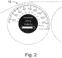
- a human machine interface (HMI) 13 is arranged to output to a vehicle 2 passenger compartment 14 information on any changes in the calculated boundary for autonomous driving availability along the planned route.
- HMI 13 An example embodiment of such an HMI 13, arranged at the dashboard of a vehicle 2, is illustrated in figure 2 .
- the HMI 13 may be arranged to present the information graphically to a display, e.g. as an automation level, where the bar indicates a distance to the calculated boundary for autonomous driving availability.
- the proximity to the calculated boundary for autonomous driving availability is here indicated by the extension of the bar from the marking "0" towards the marking "1".
- the HMI 13 may also be arranged to present the information as any suitable graphical element, as audible information and/or as tactile information, e.g. through vibrations to a vehicle driver seat or similar, or any combination of the above elements.
- the apparatus 1 continuously informs a driver of the vehicle 2 having autonomous driving capabilities where such autonomous driving is predicted to be possible and not possible.
- the processor 12 is arranged to continuously calculate the boundary for autonomous driving availability using an algorithm and to communicate this boundary using the HMI 13.
- the boundary for autonomous driving availability changes continuously and predicts a traffic situation a certain time ahead.
- the prediction time needs to be sufficient to allow a driver of the vehicle 2 to take over the responsibility for control of the vehicle 2.
- the prediction time must be short in order not to generate false manual control requests.
- the boundary for autonomous driving availability will change depending on variables that, as indicated above, include: driver distraction as indicated by vehicle driver monitoring information 10, vehicle speed as indicated by vehicle dynamics parameters or a GPS signal, traffic density as indicated by real time traffic information 11a or vehicle surrounding information 4, geographic location as indicated by map data provided by the positioning arrangement, GPS availability, electronic horizon data, and weather conditions as indicated by real time weather information.
- the boundary function is a possibly non-linear weighting of several local functions, such as vehicle speed vs. weather conditions, resulting in a multidimensional surface.
- the resulting output is the available automation level.
- sub-functions or dimensions that are causing an automation stop may be communicated to the driver using the HMI 13.
- v_cent term is optional and aims at centering on a given velocity. This can be omitted if one makes sure that the function evaluation is performed only for relevant velocity values, e.g. only for positive velocities.
- S2 may be road type, e.g. such that discrete values of a road type coding are translated to a continuous space.
- S3 may be road conditions, such as icy road or inferior lane markings.
- S4 may indicate availability of vehicle-to-infrastructure (V2X) communication.
- S5 may be weather conditions, e.g. visibility and S6 may be driver status, as indicated by the vehicle driver monitoring arrangement 9, and so on.
- the resulting function will be a set that describes the availability of autonomous driving.
- the above set may be represented graphically by a projection to some of the planes or by evaluating it for several points around the actual operating point, e.g. as in the following example.
- Figure 3 illustrates examples of such restrictions. If heavy rain 15 or snow is present further ahead along the planned route this might be the limiting factor for autonomous driving beyond that point.
- Typical restricting information for this functionality will be map data with speed limitations and real time traffic information, real time weather information 11b etc., associated with the planned route.
- road infrastructure may restrict autonomous driving.
- a multiple lane motorway 16 with no oncoming traffic may end into a two-way traffic road 17 comprising a crossing 18. If a motorway exit or a crossing 18 is present further ahead along the planned route this might be the limiting factor for autonomous driving beyond that point.
- Typical restricting information for this functionality will be map data with road infrastructure information associated with the planned route.
- the apparatus 1 provide to a driver of the vehicle 2 information on any changes in the calculated boundary for autonomous driving availability along the planned route based on external factors limiting the vehicle's ability to drive by itself.
- the processor 12 further is arranged to calculate a hand over time, required for hand over from autonomous driving to manual driving, and to compare the calculated hand over time with the calculated boundary for autonomous driving availability and to provide a request for hand over from autonomous driving to manual driving should the comparison indicate that the calculated boundary for autonomous driving availability is within a predetermined range of the calculated hand over time.
- the apparatus 1 further comprises an interface for communicating the information to an autonomous drive control unit of the vehicle. This enables vehicle 2 systems to perform adaptations in dependence upon the available degree of automation indicated by the calculated boundary for autonomous driving availability.
- the HMI 13 further is arranged to output to the vehicle 2 passenger compartment 14 information relating to changes in automation level available with the current calculated boundary for autonomous driving availability. This enables the driver of the vehicle 2 to continuously monitor the autonomous drive whilst retaining a feeling of being in control, or at least fully aware of the intentions of the autonomous drive system.
- the HMI 13 is arranged to output the information to the vehicle passenger compartment 14 through at least one of a graphical, an audio or a tactile output arrangement.
- a graphical, an audio or a tactile output arrangement is enabled several options for ensuring that the information reaches the vehicle 2 driver, irrespective of his/her current focus.
- the arrangement for acquiring real time information 11, when present, comprises an interface for communication via one or more portable communication devices of vehicle occupants (not shown) for acquiring the real time information 11a, 11b.
- Such an interface may rely on a wired connection to one or more portable communication devices or alternatively a wireless connection to one or more portable communication devices, e.g. based on WiFi, Bluetooth or similar wireless communication technologies. This enables either the realization of a less complex and more cost effective apparatus 1 or alternatively the provision of a redundant back-up channel for acquiring the real time information 11a, 11b.
- the arrangement for acquiring real time information 11, when present, comprises an interface (not shown) for performing at least one of vehicle-to-vehicle (V2V) and vehicle-to-infrastructure (V2X) communication for acquiring the real time information.
- V2V vehicle-to-vehicle
- V2X vehicle-to-infrastructure
- Such an interface will normally rely on suitable wireless communication protocols for communicating with vehicles and infrastructures in relevant vicinity of the vehicle 2 hosting the apparatus 1. This enables the realization of an effective apparatus for acquiring real time information 11a, 11b which is highly relevant for the current surroundings.
- the apparatus 1 further comprises an interface (not shown) for communicating the information on any changes in the calculated boundary for autonomous driving availability along the planned route externally of the vehicle 2 using at least one or more portable communication devices of vehicle occupants, vehicle-to-vehicle communication and vehicle-to-infrastructure communication. This enables traffic control centers and vehicles travelling in the vicinity of the own vehicle 2 to make use of the information on any changes in the calculated boundary for autonomous driving availability along the planned route.
- boundary conditions for allowing autonomous driving are: traffic intensity; presence/absence of oncoming traffic; speed limitations; the number of adjacent lanes; information on accidents or road-work further along the planned route, etc..
- a requirement of another vehicle in front e.g. a requirement of travelling in a queue
- only being allowed to stay in the actual lane i.e. prevented from changing lanes
- only allowed to drive on highways with no oncoming traffic.
- a possible requirement to have another vehicle in front will depend on real time traffic information 11a.
- the apparatus 1 may also consider specific events, e.g. accept a short disturbance in a motorways exit, such that if a lead vehicle is required and this lead vehicle leaves the motorway, autonomous driving of the vehicle 2 may still be allowed for a limited section without a lead vehicle ahead. If the availability of potential new lead vehicles is known, motorway exits may not be restricting the calculated boundary for autonomous driving availability.
- the boundary conditions for the vehicle 2 are that it is only allowed to drive on highways (with no oncoming traffic) and another vehicle ahead, which it follows, the boundary for autonomous driving availability would normally be at a chosen highway exit, as long as the vehicle ahead (queue) is maintained, i.e. in dense traffic.
- the boundary for autonomous driving availability will be recalculated, e.g. dependent on the speed limit for autonomous driving applying to the road travelled, and an update presented to the vehicle 2 driver via the human machine interface 13.
Description
- Embodiments herein relate to an apparatus and method for continuously establishing a boundary for autonomous driving availability, in a vehicle having autonomous driving capabilities as well as an automotive vehicle having autonomous driving capabilities that comprises such an apparatus.
- One area of automotive vehicle technology that is evolving rapidly is the area of autonomous or semi-autonomous drive capabilities. This is enabled through the introduction of sensors, for sensing vehicle parameters and surroundings, and actuators, for controlling different vehicle functionalities, such as steering, throttling and braking. Increased on-board data processing capabilities ties together these sensors and actuators such that the autonomous or semi-autonomous drive capabilities are enabled.
- When the vehicle runs in autonomous mode, which means the driver does not perform maneuvers, it usually requires multiple data sources as inputs to perform the autonomous driving, such as detection of surrounding vehicles, traffic lanes, obstacles, data from navigation systems and so on. However, should one or more of these inputs not be available, there might not be sufficient information to perform autonomous driving. In such cases a driver-hand over may be requested in order to ensure road safety.
- Document
WO 2013/034347 A2 describes a controller and method for relieving the strain of a driver. - A previous document,
US8433470 , relates to a user interface for displaying an internal state of an autonomous driving system. In the event of an emergency situation identified by a control computer of the automated vehicle, it may immediately convey this information to a passenger in a variety of ways. For example, if the control computer is no longer able to control the vehicle safely, illuminated indicators may change color, to inform the user of the immediate need to take control of the steering wheel. The control computer may also send audio alerts to the passenger stating that there is an emergency and the passenger is required to take control of the steering wheel. The control computer may further use cameras to scan the passenger's eyes and/or other features. If the control computer determines that the eyes are closed or the body is slumped over (e.g. the passenger is sleeping or under the influence of drugs or alcohol), the control computer may take emergency control of the vehicle and use audible alerts to wake or otherwise get the attention of the driver. - However, during autonomous driving a vehicle driver may desire to use the time when the vehicle runs in autonomous mode, and the driver is not required to perform maneuvers, to perform other activities, e.g. resting, reading, watching a movie or similar. Being otherwise occupied will, depending on the circumstances, of course affect the vehicle driver's readiness to respond to a request to assume manual control of the vehicle.
- Another previous document,
US5774069 , relates to an auto-drive control unit which can switch a vehicle provided with an auto-drive mode from the auto-drive mode to a manual drive mode at a desired point. The scheduled location (desired point) where the vehicle is to run in the manual drive is assumed to be a safety zone of the auto-drive lane, such as an interchange. Based on detection signals from various types of sensors, an auto-drive controller controls an actuator to perform auto-drive. A changeover switch is provided to switch between the auto-drive and manual drive. When the vehicle is running in the auto-drive mode, the current position of the vehicle is continuously detected on the basis of a signal from a GPS, and the vehicle speed is checked according to a signal from a vehicle speed sensor. After checking the location and the vehicle speed, an expected time of arrival at the destination, namely the scheduled location (desired point) where the drive should be changed to the manual drive, is calculated according to such data. According to a shifting time to complete the shift to the manual drive, timing for operating the changeover switch is determined, and a message is shown on a warning display to urge a driver to operate the switch. In one embodiment, it is judged in view of a prescribed shifting time whether or not the shift from the auto-drive mode to the manual drive mode can be completed before the vehicle has reached a destination and an appropriate measure is taken according to the judged result, so that the changeover to the manual drive can be made reliably at the desired point. - However, although alerting the driver in time, so that the changeover to the manual drive can be made reliably, the message shown on the warning display urging the driver to operate the changeover switch will potentially catch an otherwise occupied driver off guard. Being caught off guard will most likely affect the vehicle driver's readiness to respond to the request to assume manual control of the vehicle.
- Embodiments herein aim to provide an improved apparatus for continuously establishing a boundary for autonomous driving availability, in a vehicle having autonomous driving capabilities, the vehicle comprising: remote sensors arranged to acquire vehicle surrounding information; and vehicle dynamics sensors arranged to determine vehicle dynamics parameters.
- This is provided through an apparatus as defined in appended
claim 1. The apparatus further comprises at least one of: a positioning arrangement arranged to provide map data with associated speed limit and road infrastructure information; a route planning arrangement; a vehicle driver monitoring arrangement arranged to provide vehicle driver monitoring information; and an arrangement for acquiring real time information, including at least one of real time traffic information and real time weather information, and further: a processor arranged to continuously calculate a boundary for autonomous driving availability based on a planned route and at least one of vehicle surrounding information, vehicle dynamics parameters, vehicle driver monitoring information, map data with associated speed limit and infrastructure information, real time traffic information and real time weather information, associated with the planned route, and a human machine interface arranged to output to a vehicle passenger compartment information on any changes in the calculated boundary for autonomous driving availability along the planned route. - The provision of a continuously calculated boundary for autonomous driving availability and a human machine interface arranged to output to a vehicle passenger compartment information on any changes in the calculated boundary for autonomous driving availability along the planned route promotes the driver's trust in the autonomous driving capabilities of the vehicle as well as increases the drivers readiness to assume manual control of the vehicle if so required.
- According to a second aspect, the processor is further arranged to calculate a hand over time, required for hand over from autonomous driving to manual driving, and to compare the calculated hand over time with the calculated boundary for autonomous driving availability and to provide a request for hand over from autonomous driving to manual driving should the comparison indicate that the calculated boundary for autonomous driving availability is within a predetermined range of the calculated hand over time.
- The provision of providing a request for hand over from autonomous driving to manual driving should a comparison indicate that the calculated boundary for autonomous driving availability is within a predetermined range of the calculated hand over time ensures that the boundary will always be such that it provides sufficient time for safe hand over from autonomous driving to manual driving, thus ensuring that the vehicle driver does not suffer a stressful and potentially dangerous transition to manual driving.
- According to a further aspect of the invention, the apparatus further comprises an interface for communicating the information on any changes in the calculated boundary for autonomous driving availability along the planned route to an autonomous drive control unit of the vehicle.
- The provision of communicating the information on any changes in the calculated boundary for autonomous driving availability along the planned route to an autonomous drive control unit of the vehicle enables vehicle systems to perform adaptations in dependence upon the available degree of automation indicated by the calculated boundary for autonomous driving availability.
- According to a fourth aspect, the human machine interface is further arranged to output to the vehicle passenger compartment information relating to changes in automation level available with the current calculated boundary for autonomous driving availability.
- The provision of a human machine interface arranged to output to the vehicle passenger compartment information relating to changes in automation level available with the current calculated boundary for autonomous driving availability enables a driver of the vehicle to become aware of why adaptations in in the autonomous drive, e.g. towards a higher or lower degree of automation, is made and also enables the driver to continuously monitor the autonomous drive whilst retaining a feeling of control.
- According to a fifth aspect, the human machine interface is arranged to output the information to the vehicle passenger compartment through at least one of a graphical, an audio or a tactile output arrangement.
- The provision of outputting the information to the vehicle passenger compartment through at least one of a graphical, an audio or a tactile output arrangement provides several options for ensuring that the information reaches the vehicle driver, irrespective of his/her current focus.
- According to a sixth aspect, the arrangement for acquiring real time information, when present, comprises an interface for communication via one or more portable communication devices of vehicle occupants for acquiring the real time information. The provision of an interface for communication via one or more portable communication devices of vehicle occupants for acquiring the real time information enables either the realization of a less complex and more cost effective apparatus or alternatively the provision of a redundant back-up channel for acquiring the real time information.
- According to a seventh aspect, the arrangement for acquiring real time information, when present, comprises an interface for performing at least one of vehicle-to-vehicle and vehicle-to-infrastructure communication for acquiring the real time information. The provision of an interface for performing at least one of vehicle-to-vehicle and vehicle-to-infrastructure communication for acquiring the real time information enables the realization of an effective apparatus for acquiring real time information which is highly relevant for the current surroundings.
- According to an eight aspect, it further comprises an interface for communicating the information on any changes in the calculated boundary for autonomous driving availability along the planned route externally of the vehicle using at least one or more portable communication devices of vehicle occupants, vehicle-to-vehicle communication and vehicle-to-infrastructure communication.
- The provision of an interface for communicating the information externally of the vehicle using at least one or more portable communication devices of vehicle occupants, vehicle-to-vehicle communication and vehicle-to-infrastructure communication enables traffic control centers and vehicles travelling in the vicinity of the own vehicle to make use of the information on any changes in the calculated boundary for autonomous driving availability along the planned route.
- Further embodiments herein aim to provide a method for continuously establishing a boundary for autonomous driving availability, in a vehicle having autonomous driving capabilities, the vehicle comprising: remote sensors arranged to acquire vehicle surrounding information; and vehicle dynamics sensors arranged to determine vehicle dynamics parameters.
- This is provided through a method as defined in appended
claim 7. This method comprises at least one of the steps of: providing map data with associated speed limit and road infrastructure information using a positioning arrangement performing route planning using a route planning arrangement monitoring a vehicle driver and providing vehicle driver monitoring information using a vehicle driver monitoring arrangement; and acquiring real time information, including at least one of real time traffic information and real time weather information, and the steps of: continuously calculating, using a processor, a boundary for autonomous driving availability based on based on a planned route and at least one of vehicle surrounding information, vehicle dynamics parameters, vehicle driver monitoring information, map data with associated speed limit and infrastructure information, real time traffic information and real time weather information, associated with the planned route, and outputting, to a human machine interface arranged in a vehicle passenger compartment, information on any changes in the calculated boundary for autonomous driving availability along the planned route. - The provision of calculating a boundary for autonomous driving availability and outputting to a human machine interface arranged in a vehicle passenger compartment this calculated boundary for autonomous driving availability enables a driver of the vehicle to confidently use an available autonomous driving capability of the vehicle whilst being prepared to respond to a request to assume manual control of the vehicle.
- According to a final aspect, an automotive vehicle having autonomous driving capabilities which comprises an apparatus for continuously establishing a boundary for autonomous driving availability as above is provided. The automotive vehicle is defined in appended
claim 8. An automotive vehicle which comprises an apparatus for continuously establishing a boundary for autonomous driving availability in a vehicle having autonomous driving capabilities and to output to a vehicle passenger compartment this calculated boundary for autonomous driving availability enables a driver of the vehicle to confidently use an available autonomous driving capability of the vehicle whilst being prepared to respond to a request to assume manual control of the vehicle. - In the following, embodiments herein will be described in greater detail by way of example only with reference to attached drawings, in which
-
Fig. 1 is a schematic illustration of an apparatus for continuously establishing a boundary for autonomous driving availability, in a vehicle having autonomous driving capabilities according to embodiments herein. -
Fig. 2 is a schematic illustration of a human machine interface arranged to output to a vehicle passenger compartment information on any changes in the calculated boundary for autonomous driving availability along a planned route according to embodiments herein. -
Fig.3 is a schematic illustration of road infrastructure, traffic and weather conditions along a planned route according to embodiments herein. - Still other objects and features of embodiments herein will become apparent from the following detailed description considered in conjunction with the accompanying drawings. It is to be understood, however, that the drawings are designed solely for purposes of illustration and not as a definition of the limits hereof, for which reference should be made to the appended claims. It should be further understood that the drawings are not necessarily drawn to scale and that, unless otherwise indicated, they are merely intended to conceptually illustrate the structures and procedures described herein.
- In overview, embodiments herein relate to an
apparatus 1 for continuously establishing a boundary for autonomous driving availability in avehicle 2 having autonomous driving capabilities, thevehicle 2 comprising:remote sensors 3 arranged to acquire vehicle surrounding information 4; andvehicle dynamics sensors 5 arranged to determinevehicle dynamics parameters 6, as illustrated infigure 1 - In many traffic situations a driver today will have a rather low workload, as the driving task as such is rather uncomplicated (e.g. when driving on high-ways and on country roads with fence separation from on-coming traffic). Even with today's limited sensing systems, such situations could be handled by the vehicle itself, in a fully automated mode. However, the
apparatus 1 herein described is based on the realization that a driver needs to be continuously informed where such autonomous driving situations are predicted to be possible or rather where such autonomous driving situations are deemed not possible. - A
vehicle 2 having autonomous driving capabilities will include a vehicle controller (not shown) for controlling unmanned autonomous driving. The vehicle controller will e.g. pursue a route to a final destination, and control thevehicle 2 so that thevehicle 2 can perform autonomous driving along the route to the final destination in an unmanned manner. Usually, when a fixed or movable obstacle is present in the route to the final destination, the vehicle controller will detect the object, using vehicleremote sensor systems 3 such as one or more of a Radio Detection And Ranging (RADAR) sensor, a Light Detection And Ranging (LIDAR) sensor, a Light Amplification by Stimulated Emission of Radiation (LASER) sensor, an ultrasound sensor, an infrared sensor, an image sensor, or any combination thereof. Thereafter the vehicle controller will control vehicle actuators (not shown), such as steering, braking and throttle actuators, in order to avoid the detected obstacle, or temporarily haltvehicle 2 travel in order to avoid a collision with the detected object. - The vehicle controller, of the
vehicle 2 having autonomous driving capabilities, may also comprise or be arranged to control sub-systems such as cruise control systems, so-called ACC (Adaptive Cruise Control) systems, which monitor the front area of thevehicle 2, with the aid of e.g. a radar sensor, and automatically regulate the distance to a preceding vehicle, as well as automatic lane-keeping systems and combinations of such systems. - The
apparatus 1 further comprises at least one of: apositioning arrangement 7 arranged to provide map data with associated speed limit and road infrastructure information; aroute planning arrangement 8; a vehicledriver monitoring arrangement 9 arranged to provide vehicledriver monitoring information 10; and an arrangement for acquiringreal time information 11, including at least one of realtime traffic information 11a and realtime weather information 11b. - The
positioning arrangement 7, when present, is, as mentioned above, arranged to provide map data with associated speed limit and road infrastructure information. The positioning arrangement may comprise a navigation system, such as a global positioning system (GPS) or equivalent. - The
route planning arrangement 8, when present, is provided by theapparatus 1, such that a route to be travelled may be planned by avehicle 2 driver, a traffic control center, a logistics center or similar. Route planning may be made using an interface (not shown) provided in apassenger compartment 14 of thevehicle 2 or alternatively via a remote interface (not shown) arranged to communicate with theroute planning arrangement 8, e.g. through a wireless communication network. - If the autonomous driving capability is simply activated on a road travelled, without any knowledge of a planned route, establishing of a boundary for autonomous driving availability will suitably be based on road infrastructure, such as the presence of motorway exits, crossings and other potentially limiting infrastructure elements along the road travelled. In this case the boundary for autonomous driving availability will have to be adapted to allow a driver to take control before e.g. the next exit, in order to be able to make a decision to exit the road or to continue driving thereupon.
- The vehicle
driver monitoring arrangement 9, when present, is arranged to provide vehicledriver monitoring information 10, e.g. from a driver monitoring camera. - The arrangement for acquiring
real time information 11, when present, includes an arrangement for acquiring at least one of realtime traffic information 11a and realtime weather information 11b. - Further, a
processor 12 is arranged to continuously calculate a boundary for autonomous driving availability based on a planned route and at least one of vehicle surrounding information 4,vehicle dynamics parameters 6, vehicledriver monitoring information 10, map data with associated speed limit and infrastructure information, realtime traffic information 11a and realtime weather information 11a, associated with the planned route. If a predefined route has been planned more information will be available to theprocessor 12, thus enabling it to more accurately establish the boundary for autonomous driving availability. - In order to enable a driver of the
vehicle 2 to confidently use the autonomous driving functionality a human machine interface (HMI) 13 is arranged to output to avehicle 2passenger compartment 14 information on any changes in the calculated boundary for autonomous driving availability along the planned route. Hereby the driver can confidently monitor a current status of an autonomous driving session. An example embodiment of such anHMI 13, arranged at the dashboard of avehicle 2, is illustrated infigure 2 . As illustrated, theHMI 13 may be arranged to present the information graphically to a display, e.g. as an automation level, where the bar indicates a distance to the calculated boundary for autonomous driving availability. The proximity to the calculated boundary for autonomous driving availability is here indicated by the extension of the bar from the marking "0" towards the marking "1". TheHMI 13 may also be arranged to present the information as any suitable graphical element, as audible information and/or as tactile information, e.g. through vibrations to a vehicle driver seat or similar, or any combination of the above elements. Thus, theapparatus 1 continuously informs a driver of thevehicle 2 having autonomous driving capabilities where such autonomous driving is predicted to be possible and not possible. - The
processor 12 is arranged to continuously calculate the boundary for autonomous driving availability using an algorithm and to communicate this boundary using theHMI 13. The boundary for autonomous driving availability changes continuously and predicts a traffic situation a certain time ahead. The prediction time needs to be sufficient to allow a driver of thevehicle 2 to take over the responsibility for control of thevehicle 2. However, the prediction time must be short in order not to generate false manual control requests. The boundary for autonomous driving availability will change depending on variables that, as indicated above, include: driver distraction as indicated by vehicledriver monitoring information 10, vehicle speed as indicated by vehicle dynamics parameters or a GPS signal, traffic density as indicated by realtime traffic information 11a or vehicle surrounding information 4, geographic location as indicated by map data provided by the positioning arrangement, GPS availability, electronic horizon data, and weather conditions as indicated by real time weather information. The boundary function is a possibly non-linear weighting of several local functions, such as vehicle speed vs. weather conditions, resulting in a multidimensional surface. The resulting output is the available automation level. During operation sub-functions or dimensions that are causing an automation stop may be communicated to the driver using theHMI 13. - Such an algorithm, suitable for use by the
processor 12 to continuously calculate the boundary for autonomous driving availability, may e.g. be based on set-theory. For example, if one considers the following set description S=S1+S2+S3+···, where
- showing autonomous driving availability with respect to velocity. The v_cent term is optional and aims at centering on a given velocity. This can be omitted if one makes sure that the function evaluation is performed only for relevant velocity values, e.g. only for positive velocities. Similarly, S2 may be road type, e.g. such that discrete values of a road type coding are translated to a continuous space. S3 may be road conditions, such as icy road or inferior lane markings. S4 may indicate availability of vehicle-to-infrastructure (V2X) communication. S5 may be weather conditions, e.g. visibility and S6 may be driver status, as indicated by the vehicle
driver monitoring arrangement 9, and so on. - The resulting function will be a set that describes the availability of autonomous driving. The above set may be represented graphically by a projection to some of the planes or by evaluating it for several points around the actual operating point, e.g. as in the following example.
- Consider that the actual operating point is v=50 kph, icy road, vehicle-to-infrastructure communication unavailable. Evaluating S will result in a scalar. Now this may be displayed on a bar as a single point, where the bar is obtained by evaluating the function for a velocity interval. Should an evaluation of the actual operating point provide a result above a given threshold, than autonomous driving is available. This information can be used for controlling the
vehicle 2 and/or relaying any autonomous driving limiting information to the driver of thevehicle 2. - As mentioned above, environmental conditions may restrict autonomous driving.
Figure 3 illustrates examples of such restrictions. Ifheavy rain 15 or snow is present further ahead along the planned route this might be the limiting factor for autonomous driving beyond that point. Typical restricting information for this functionality will be map data with speed limitations and real time traffic information, realtime weather information 11b etc., associated with the planned route. - Further, road infrastructure may restrict autonomous driving. For example a
multiple lane motorway 16 with no oncoming traffic may end into a two-way traffic road 17 comprising acrossing 18. If a motorway exit or a crossing 18 is present further ahead along the planned route this might be the limiting factor for autonomous driving beyond that point. Typical restricting information for this functionality will be map data with road infrastructure information associated with the planned route. - Thus, the
apparatus 1 provide to a driver of thevehicle 2 information on any changes in the calculated boundary for autonomous driving availability along the planned route based on external factors limiting the vehicle's ability to drive by itself. - In embodiments hereof the
processor 12 further is arranged to calculate a hand over time, required for hand over from autonomous driving to manual driving, and to compare the calculated hand over time with the calculated boundary for autonomous driving availability and to provide a request for hand over from autonomous driving to manual driving should the comparison indicate that the calculated boundary for autonomous driving availability is within a predetermined range of the calculated hand over time. - Hereby is ensured that the boundary will always be such that it provides sufficient time for safe hand over from autonomous driving to manual driving, thus ensuring that the
vehicle 2 driver does not suffer a stressful and potentially dangerous transition to manual driving. - In further embodiments hereof the
apparatus 1 further comprises an interface for communicating the information to an autonomous drive control unit of the vehicle. This enablesvehicle 2 systems to perform adaptations in dependence upon the available degree of automation indicated by the calculated boundary for autonomous driving availability. - In other embodiments hereof the
HMI 13 further is arranged to output to thevehicle 2passenger compartment 14 information relating to changes in automation level available with the current calculated boundary for autonomous driving availability. This enables the driver of thevehicle 2 to continuously monitor the autonomous drive whilst retaining a feeling of being in control, or at least fully aware of the intentions of the autonomous drive system. - In still further embodiments hereof the
HMI 13 is arranged to output the information to thevehicle passenger compartment 14 through at least one of a graphical, an audio or a tactile output arrangement. Hereby is enabled several options for ensuring that the information reaches thevehicle 2 driver, irrespective of his/her current focus. - In further embodiments hereof the arrangement for acquiring
real time information 11, when present, comprises an interface for communication via one or more portable communication devices of vehicle occupants (not shown) for acquiring thereal time information effective apparatus 1 or alternatively the provision of a redundant back-up channel for acquiring thereal time information - In yet further embodiments the arrangement for acquiring
real time information 11, when present, comprises an interface (not shown) for performing at least one of vehicle-to-vehicle (V2V) and vehicle-to-infrastructure (V2X) communication for acquiring the real time information. Such an interface will normally rely on suitable wireless communication protocols for communicating with vehicles and infrastructures in relevant vicinity of thevehicle 2 hosting theapparatus 1. This enables the realization of an effective apparatus for acquiringreal time information - In still further embodiments hereof the
apparatus 1 further comprises an interface (not shown) for communicating the information on any changes in the calculated boundary for autonomous driving availability along the planned route externally of thevehicle 2 using at least one or more portable communication devices of vehicle occupants, vehicle-to-vehicle communication and vehicle-to-infrastructure communication. This enables traffic control centers and vehicles travelling in the vicinity of theown vehicle 2 to make use of the information on any changes in the calculated boundary for autonomous driving availability along the planned route. - Further possible boundary conditions for allowing autonomous driving, and thus affecting the calculated boundary for autonomous driving availability, are: traffic intensity; presence/absence of oncoming traffic; speed limitations; the number of adjacent lanes; information on accidents or road-work further along the planned route, etc..
- Other possible boundary conditions could be: a requirement of another vehicle in front (e.g. a requirement of travelling in a queue); only being allowed to stay in the actual lane (i.e. prevented from changing lanes); only allowed to drive on highways (with no oncoming traffic). A possible requirement to have another vehicle in front will depend on real
time traffic information 11a. Theapparatus 1 may also consider specific events, e.g. accept a short disturbance in a motorways exit, such that if a lead vehicle is required and this lead vehicle leaves the motorway, autonomous driving of thevehicle 2 may still be allowed for a limited section without a lead vehicle ahead. If the availability of potential new lead vehicles is known, motorway exits may not be restricting the calculated boundary for autonomous driving availability. - If, for example, the boundary conditions for the
vehicle 2 are that it is only allowed to drive on highways (with no oncoming traffic) and another vehicle ahead, which it follows, the boundary for autonomous driving availability would normally be at a chosen highway exit, as long as the vehicle ahead (queue) is maintained, i.e. in dense traffic. However, should the realtime traffic information 11a indicate that the queue is breaking up, such that it becomes difficult to maintain the requirement of another vehicle ahead, the boundary for autonomous driving availability will be recalculated, e.g. dependent on the speed limit for autonomous driving applying to the road travelled, and an update presented to thevehicle 2 driver via thehuman machine interface 13. - Although the above description mainly describes passenger car vehicles, the teachings provided herein may, without loss of generality, be expanded to consider commercial vehicles, such as buses, trucks and similar vehicles having autonomous driving capabilities, without loss of generality. The above-described embodiments may be varied within the scope of the following claims.
- Thus, while there have been shown and described and pointed out fundamental novel features of the embodiments herein, it will be understood that various omissions and substitutions and changes in the form and details of the devices illustrated, and in their operation, may be made by those skilled in the art. For example, it is expressly intended that all combinations of those elements and/or method steps which perform substantially the same function in substantially the same way to achieve the same results are equivalent. Moreover, it should be recognized that structures and/or elements and/or method steps shown and/or described in connection with any disclosed form or embodiment herein may be incorporated in any other disclosed or described or suggested form or embodiment as a general matter of design choice.
Claims (8)
- An apparatus (1) for continuously establishing a boundary for autonomous driving availability in a vehicle (2) having autonomous driving capabilities, the vehicle (2) comprising:sensors (3) arranged to acquire vehicle surrounding information (4);vehicle dynamics sensors (5) arranged to determine vehicle dynamics parameters (6);further comprising:at least one of: a positioning arrangement (7) arranged to provide map data with associated speed limit and road infrastructure information; a route planning arrangement (8); a vehicle driver monitoring arrangement (9) arranged to provide vehicle driver monitoring information (10); and an arrangement for acquiring real time information (11), including at least one of real time traffic information (11a) and real time weather information (11b), anda processor (12) arranged to continuously calculate a boundary for autonomous driving availability based on a planned route and at least one of vehicle surrounding information (4), vehicle dynamics parameters (6), vehicle driver monitoring information (10), map data with associated speed limit and infrastructure information, real time traffic information (11a) and real time weather information (11b), associated with the planned route, andcharacterized in that it further comprises:a human machine interface (13) arranged to output to a vehicle (2) passenger compartment (14) information on any changes in the calculated boundary for autonomous driving availability along the planned route,wherein the human machine interface (13) is arranged to present the information graphically to a display indicating a distance to the calculated boundary for autonomous driving availability.
- An apparatus (1) according to claim 1, characterized in that it further comprises an interface for communicating the information on any changes in the calculated boundary for autonomous driving availability along the planned route to an autonomous drive control unit of the vehicle.
- An apparatus (1) according to any one of claims 1 to 2, characterized in that the human machine interface (13) further is arranged to output to the vehicle (2) passenger compartment (14) information relating to changes in automation level available with the current calculated boundary for autonomous driving availability.
- An apparatus (1) according to any one of claims 1 to 3, characterized in that the arrangement for acquiring real time information (11), when present, comprises an interface for communication via one or more portable communication devices of vehicle (2) occupants for acquiring the real time information.
- An apparatus (1) according to any one of claims 1 to 4, characterized in that the arrangement for acquiring real time information (11), when present, comprises an interface for performing at least one of vehicle-to-vehicle and vehicle-to-infrastructure communication for acquiring the real time information.
- An apparatus (1) according to any one of claims 1 to 5, characterized in that it further comprises an interface for communicating the information on any changes in the calculated boundary for autonomous driving availability along the planned route externally of the vehicle (2) using at least one or more portable communication devices of vehicle (2) occupants, vehicle-to-vehicle communication and vehicle-to-infrastructure communication.
- A method for continuously establishing a boundary for autonomous driving availability in a vehicle (2) having autonomous driving capabilities, the vehicle (2) comprising:sensors (3) arranged to acquire vehicle surrounding information (4);vehicle dynamics sensors (5) arranged to determine vehicle dynamics parameters (6);the method comprising at least one of the steps of:providing map data with associated speed limit and road infrastructure information using a positioning arrangement (7);performing route planning using a route planning arrangement (8);monitoring a vehicle driver and providing vehicle driver monitoring information (10) using a vehicle driver monitoring arrangement (9); andacquiring real time information, including at least one of real time traffic information (11a) and real time weather information (11b), and the step of:
continuously calculating, using a processor (12), a boundary for autonomous driving availability based on based on a planned route and at least one of vehicle surrounding information (4), vehicle dynamics parameters (6), vehicle driver monitoring information (10), map data with associated speed limit and infrastructure information, real time traffic information (11a) and real time weather information (11b), associated with the planned route,characterized in that the method further comprises:
outputting, to a human machine interface (13) arranged in a vehicle (2) passenger compartment (14), information on any changes in the calculated boundary for autonomous driving availability along the planned route,wherein the human machine interface (13) is arranged to present the information graphically to a display indicating a distance to the calculated boundary for autonomous driving availability. - An automotive vehicle (2) having autonomous driving capabilities characterized in that it comprises an apparatus (1) for continuously establishing a boundary for autonomous driving availability according to any one of claims 1 to 6.
Priority Applications (3)
| Application Number | Priority Date | Filing Date | Title |
|---|---|---|---|
| EP14157579.5A EP2915718B1 (en) | 2014-03-04 | 2014-03-04 | Apparatus and method for continuously establishing a boundary for autonomous driving availability and an automotive vehicle comprising such an apparatus |
| US14/629,805 US9594373B2 (en) | 2014-03-04 | 2015-02-24 | Apparatus and method for continuously establishing a boundary for autonomous driving availability and an automotive vehicle comprising such an apparatus |
| CN201510204317.1A CN104973071B (en) | 2014-03-04 | 2015-02-25 | Persistently establish the device and method and associated vehicle on the boundary of automatic Pilot availability |
Applications Claiming Priority (1)
| Application Number | Priority Date | Filing Date | Title |
|---|---|---|---|
| EP14157579.5A EP2915718B1 (en) | 2014-03-04 | 2014-03-04 | Apparatus and method for continuously establishing a boundary for autonomous driving availability and an automotive vehicle comprising such an apparatus |
Publications (2)
| Publication Number | Publication Date |
|---|---|
| EP2915718A1 EP2915718A1 (en) | 2015-09-09 |
| EP2915718B1 true EP2915718B1 (en) | 2018-07-11 |
Family
ID=50193331
Family Applications (1)
| Application Number | Title | Priority Date | Filing Date |
|---|---|---|---|
| EP14157579.5A Active EP2915718B1 (en) | 2014-03-04 | 2014-03-04 | Apparatus and method for continuously establishing a boundary for autonomous driving availability and an automotive vehicle comprising such an apparatus |
Country Status (3)
| Country | Link |
|---|---|
| US (1) | US9594373B2 (en) |
| EP (1) | EP2915718B1 (en) |
| CN (1) | CN104973071B (en) |
Families Citing this family (124)
| Publication number | Priority date | Publication date | Assignee | Title |
|---|---|---|---|---|
| KR102200121B1 (en) * | 2014-02-17 | 2021-01-08 | 삼성전자 주식회사 | Apparatus and method forecasting vehicle flow |
| US10373259B1 (en) | 2014-05-20 | 2019-08-06 | State Farm Mutual Automobile Insurance Company | Fully autonomous vehicle insurance pricing |
| US9972054B1 (en) | 2014-05-20 | 2018-05-15 | State Farm Mutual Automobile Insurance Company | Accident fault determination for autonomous vehicles |
| US20210133871A1 (en) | 2014-05-20 | 2021-05-06 | State Farm Mutual Automobile Insurance Company | Autonomous vehicle operation feature usage recommendations |
| US11669090B2 (en) | 2014-05-20 | 2023-06-06 | State Farm Mutual Automobile Insurance Company | Autonomous vehicle operation feature monitoring and evaluation of effectiveness |
| US10599155B1 (en) | 2014-05-20 | 2020-03-24 | State Farm Mutual Automobile Insurance Company | Autonomous vehicle operation feature monitoring and evaluation of effectiveness |
| JP6115520B2 (en) * | 2014-05-30 | 2017-04-19 | 株式会社デンソー | Driving assistance device |
| US9783159B1 (en) | 2014-07-21 | 2017-10-10 | State Farm Mutual Automobile Insurance Company | Methods of theft prevention or mitigation |
| KR20160013713A (en) * | 2014-07-28 | 2016-02-05 | 현대자동차주식회사 | Global path generation apparatus for autonomous vehicle and method thereof |
| US9892296B2 (en) | 2014-11-12 | 2018-02-13 | Joseph E. Kovarik | Method and system for autonomous vehicles |
| US20210118249A1 (en) * | 2014-11-13 | 2021-04-22 | State Farm Mutual Automobile Insurance Company | Autonomous vehicle salvage and repair |
| WO2016109482A1 (en) * | 2014-12-29 | 2016-07-07 | Robert Bosch Gmbh | Drive state indicator for an autonomous vehicle |
| KR101659034B1 (en) * | 2015-01-20 | 2016-09-23 | 엘지전자 주식회사 | Apparatus for switching driving mode of vehicle and method thereof |
| EP3705972A1 (en) * | 2015-05-13 | 2020-09-09 | Uber Technologies, Inc. | Autonomous vehicle operated with guide assistance |
| US9870649B1 (en) | 2015-08-28 | 2018-01-16 | State Farm Mutual Automobile Insurance Company | Shared vehicle usage, monitoring and feedback |
| JP6746306B2 (en) * | 2015-12-03 | 2020-08-26 | アルパイン株式会社 | Automatic driving control support device and automatic driving control support method |
| US9699289B1 (en) | 2015-12-09 | 2017-07-04 | Toyota Motor Engineering & Manufacturing North America, Inc. | Dynamic vehicle automation level availability indication system and method |
| US10386192B1 (en) | 2016-01-22 | 2019-08-20 | State Farm Mutual Automobile Insurance Company | Autonomous vehicle routing |
| US11719545B2 (en) | 2016-01-22 | 2023-08-08 | Hyundai Motor Company | Autonomous vehicle component damage and salvage assessment |
| US10134278B1 (en) | 2016-01-22 | 2018-11-20 | State Farm Mutual Automobile Insurance Company | Autonomous vehicle application |
| US11441916B1 (en) | 2016-01-22 | 2022-09-13 | State Farm Mutual Automobile Insurance Company | Autonomous vehicle trip routing |
| US10324463B1 (en) | 2016-01-22 | 2019-06-18 | State Farm Mutual Automobile Insurance Company | Autonomous vehicle operation adjustment based upon route |
| US10395332B1 (en) | 2016-01-22 | 2019-08-27 | State Farm Mutual Automobile Insurance Company | Coordinated autonomous vehicle automatic area scanning |
| US11242051B1 (en) | 2016-01-22 | 2022-02-08 | State Farm Mutual Automobile Insurance Company | Autonomous vehicle action communications |
| US10144408B2 (en) * | 2016-01-29 | 2018-12-04 | Faraday & Future Inc. | System and method for assisting navigation of vehicle through traffic |
| JP6455456B2 (en) * | 2016-02-16 | 2019-01-23 | トヨタ自動車株式会社 | Vehicle control device |
| US10289113B2 (en) * | 2016-02-25 | 2019-05-14 | Ford Global Technologies, Llc | Autonomous occupant attention-based control |
| US10026317B2 (en) * | 2016-02-25 | 2018-07-17 | Ford Global Technologies, Llc | Autonomous probability control |
| EP3575173B1 (en) | 2016-03-03 | 2022-07-20 | Volvo Truck Corporation | A vehicle with autonomous driving capability |
| CN107316457B (en) * | 2016-04-27 | 2020-07-14 | 上海炬宏信息技术有限公司 | Method for judging whether road traffic condition accords with automatic driving of automobile |
| JP6699831B2 (en) * | 2016-04-28 | 2020-05-27 | トヨタ自動車株式会社 | Driving awareness estimation device |
| WO2017192358A1 (en) | 2016-05-06 | 2017-11-09 | Pcms Holdings, Inc. | Method and system for collaborative sensing for updating dynamic map layers |
| US9829884B1 (en) * | 2016-05-10 | 2017-11-28 | Dura Operating, Llc | Scalable driver assistance system |
| JP6337382B2 (en) * | 2016-05-19 | 2018-06-06 | 本田技研工業株式会社 | Vehicle control system, traffic information sharing system, vehicle control method, and vehicle control program |
| US10059346B2 (en) * | 2016-06-07 | 2018-08-28 | Ford Global Technologies, Llc | Driver competency during autonomous handoff |
| JP6493311B2 (en) * | 2016-06-07 | 2019-04-03 | 株式会社デンソー | VEHICLE DEVICE AND VEHICLE SYSTEM |
| US11092446B2 (en) | 2016-06-14 | 2021-08-17 | Motional Ad Llc | Route planning for an autonomous vehicle |
| US10126136B2 (en) * | 2016-06-14 | 2018-11-13 | nuTonomy Inc. | Route planning for an autonomous vehicle |
| US10309792B2 (en) | 2016-06-14 | 2019-06-04 | nuTonomy Inc. | Route planning for an autonomous vehicle |
| JP6778872B2 (en) * | 2016-06-28 | 2020-11-04 | パナソニックIpマネジメント株式会社 | Driving support device and driving support method |
| US10829116B2 (en) | 2016-07-01 | 2020-11-10 | nuTonomy Inc. | Affecting functions of a vehicle based on function-related information about its environment |
| US10260898B2 (en) * | 2016-07-12 | 2019-04-16 | Toyota Motor Engineering & Manufacturing North America, Inc. | Apparatus and method of determining an optimized route for a highly automated vehicle |
| US10272783B2 (en) * | 2016-07-15 | 2019-04-30 | Toyota Motor Engineering & Manufacturing North America, Inc. | Driver and vehicle responsibility matrix |
| CN106020205B (en) * | 2016-07-22 | 2018-11-02 | 百度在线网络技术(北京)有限公司 | A kind of unmanned vehicle energy saving of system control method and device |
| DE102016009763A1 (en) * | 2016-08-11 | 2018-02-15 | Trw Automotive Gmbh | Control system and control method for determining a trajectory and generating associated signals or control commands |
| US10775805B2 (en) * | 2016-08-26 | 2020-09-15 | Crown Equipment Limited | Materials handling vehicle path validation and dynamic path modification |
| JP6544320B2 (en) * | 2016-08-26 | 2019-07-17 | トヨタ自動車株式会社 | Control system and control method of autonomous driving vehicle |
| JP6519555B2 (en) * | 2016-08-26 | 2019-05-29 | トヨタ自動車株式会社 | Information processing device |
| JP6597520B2 (en) * | 2016-08-26 | 2019-10-30 | トヨタ自動車株式会社 | Information processing device |
| US10606276B2 (en) * | 2016-09-30 | 2020-03-31 | Faraday & Future Inc. | User data-based autonomous vehicle system |
| US10473470B2 (en) | 2016-10-20 | 2019-11-12 | nuTonomy Inc. | Identifying a stopping place for an autonomous vehicle |
| US10331129B2 (en) | 2016-10-20 | 2019-06-25 | nuTonomy Inc. | Identifying a stopping place for an autonomous vehicle |
| DE102016220549A1 (en) * | 2016-10-20 | 2018-04-26 | Robert Bosch Gmbh | A method and apparatus for assisting a driver in disabling a highly automated driving mode of a vehicle |
| US10681513B2 (en) | 2016-10-20 | 2020-06-09 | nuTonomy Inc. | Identifying a stopping place for an autonomous vehicle |
| US10857994B2 (en) | 2016-10-20 | 2020-12-08 | Motional Ad Llc | Identifying a stopping place for an autonomous vehicle |
| JP6493923B2 (en) * | 2016-11-08 | 2019-04-03 | 本田技研工業株式会社 | Information display device, information display method, and information display program |
| KR20190087560A (en) * | 2016-11-28 | 2019-07-24 | 텔레호낙티에볼라게트 엘엠 에릭슨(피유비엘) | Prediction-based client control |
| CN110214297A (en) * | 2016-12-22 | 2019-09-06 | 日产北美公司 | The remote system of automatic driving vehicle |
| US10082869B2 (en) * | 2017-02-03 | 2018-09-25 | Qualcomm Incorporated | Maintaining occupant awareness in vehicles |
| KR102199093B1 (en) | 2017-02-10 | 2021-01-06 | 닛산 노쓰 아메리카, 인크. | Self-driving vehicle operation management, including operating a partially observable Markov decision process model instance |
| BR112019016278A2 (en) | 2017-02-10 | 2020-04-07 | Nissan North America, Inc. | autonomous vehicle operational management lock monitoring |
| EP3580620B1 (en) | 2017-02-10 | 2023-09-06 | Nissan North America, Inc. | Autonomous vehicle operational management control |
| JP6593712B2 (en) * | 2017-03-30 | 2019-10-23 | マツダ株式会社 | Vehicle driving support system |
| JP6555648B2 (en) * | 2017-03-30 | 2019-08-07 | マツダ株式会社 | Vehicle driving support system |
| JP6555647B2 (en) * | 2017-03-30 | 2019-08-07 | マツダ株式会社 | Vehicle driving support system and vehicle driving support method |
| JP6729794B2 (en) * | 2017-03-31 | 2020-07-22 | 日産自動車株式会社 | Operation control method and operation control device |
| EP3611469B1 (en) * | 2017-04-12 | 2022-11-23 | Nissan Motor Co., Ltd. | Driving control method and driving control device |
| JP6911116B2 (en) * | 2017-06-27 | 2021-07-28 | 本田技研工業株式会社 | Vehicle control device |
| DE102017211556A1 (en) * | 2017-07-06 | 2019-01-10 | Robert Bosch Gmbh | Method for route planning for a motor vehicle with an automated vehicle system and motor vehicle with an automated vehicle system |
| FR3068945B1 (en) * | 2017-07-11 | 2019-08-30 | Institut Francais Des Sciences Et Technologies Des Transports, De L'amenagement Et Des Reseaux | ROAD VEHICLE AND METHOD OF REINSTATEMENT OF THE MANUAL DRIVE |
| US10261514B2 (en) * | 2017-08-16 | 2019-04-16 | Uber Technologies, Inc. | Systems and methods for communicating autonomous vehicle scenario evaluation and intended vehicle actions |
| JP6984232B2 (en) * | 2017-08-25 | 2021-12-17 | トヨタ自動車株式会社 | Autonomous driving device |
| US10836405B2 (en) | 2017-10-30 | 2020-11-17 | Nissan North America, Inc. | Continual planning and metareasoning for controlling an autonomous vehicle |
| US11702070B2 (en) | 2017-10-31 | 2023-07-18 | Nissan North America, Inc. | Autonomous vehicle operation with explicit occlusion reasoning |
| WO2019088989A1 (en) | 2017-10-31 | 2019-05-09 | Nissan North America, Inc. | Reinforcement and model learning for vehicle operation |
| DE102017220139A1 (en) * | 2017-11-13 | 2019-05-16 | Robert Bosch Gmbh | Method and device for providing a position of at least one object |
| US11084504B2 (en) | 2017-11-30 | 2021-08-10 | Nissan North America, Inc. | Autonomous vehicle operational management scenarios |
| US20190185012A1 (en) * | 2017-12-18 | 2019-06-20 | PlusAI Corp | Method and system for personalized motion planning in autonomous driving vehicles |
| US11130497B2 (en) * | 2017-12-18 | 2021-09-28 | Plusai Limited | Method and system for ensemble vehicle control prediction in autonomous driving vehicles |
| US11874120B2 (en) | 2017-12-22 | 2024-01-16 | Nissan North America, Inc. | Shared autonomous vehicle operational management |
| US10583839B2 (en) * | 2017-12-28 | 2020-03-10 | Automotive Research & Testing Center | Method of lane change decision-making and path planning |
| WO2019164531A1 (en) | 2018-02-26 | 2019-08-29 | Nissan North America, Inc. | Centralized shared autonomous vehicle operational management |
| JP2019156144A (en) * | 2018-03-13 | 2019-09-19 | 本田技研工業株式会社 | Vehicle controller, vehicle control method and program |
| US10752249B2 (en) * | 2018-03-14 | 2020-08-25 | Toyota Research Institute, Inc. | Vehicle systems and methods for providing turn assistance at an intersection |
| GB2572200B (en) * | 2018-03-23 | 2020-09-23 | Jaguar Land Rover Ltd | Vehicle controller and control method |
| US20210024097A1 (en) * | 2018-03-23 | 2021-01-28 | Jaguar Land Rover Limited | Vehicle controller and control method |
| FR3079804B1 (en) * | 2018-04-06 | 2020-09-04 | Renault Sas | METHOD AND SYSTEM FOR ASSISTANCE TO THE DRIVER OF A MOTOR VEHICLE EQUIPPED WITH A DRIVING ASSISTANCE SYSTEM |
| DE112019002067T5 (en) | 2018-04-20 | 2021-02-04 | Sony Semiconductor Solutions Corporation | Information processing device, mobile device, information processing system, method and program |
| US20190369614A1 (en) * | 2018-05-31 | 2019-12-05 | GM Global Technology Operations LLC | System and method for controlling an autonomous vehicle |
| US11120688B2 (en) * | 2018-06-29 | 2021-09-14 | Nissan North America, Inc. | Orientation-adjust actions for autonomous vehicle operational management |
| CN109068265A (en) * | 2018-07-16 | 2018-12-21 | 武汉小安科技有限公司 | Quickly method, system, server and the storage medium of binding account and vehicle |
| US10852726B2 (en) | 2018-11-13 | 2020-12-01 | Toyota Research Institute, Inc. | Systems and methods for transitioning a vehicle from an autonomous driving mode to a manual driving mode |
| JP2022516559A (en) | 2019-01-03 | 2022-02-28 | エッジ ケース リサーチ,インコーポレイテッド | Methods and systems to improve tolerance while ensuring the safety of autonomous vehicles |
| EP3693240A1 (en) * | 2019-02-06 | 2020-08-12 | Zenuity AB | Control of activation threshold for vehicle safety systems |
| DE102019124979A1 (en) * | 2019-09-17 | 2021-03-18 | Valeo Schalter Und Sensoren Gmbh | Automatic switching from manual mode to autonomous mode for a vehicle |
| DE102019215656B4 (en) * | 2019-10-11 | 2021-07-22 | Zf Friedrichshafen Ag | Method for evaluating a selected route, route evaluation system and computer program |
| EP3822140B1 (en) * | 2019-11-18 | 2022-06-22 | Zenuity AB | Operational design domain validation coverage for road and lane type |
| US11899454B2 (en) | 2019-11-26 | 2024-02-13 | Nissan North America, Inc. | Objective-based reasoning in autonomous vehicle decision-making |
| US11635758B2 (en) | 2019-11-26 | 2023-04-25 | Nissan North America, Inc. | Risk aware executor with action set recommendations |
| CN111026111A (en) * | 2019-11-29 | 2020-04-17 | 上海电机学院 | Automobile intelligent driving control system based on 5G network |
| US11613269B2 (en) | 2019-12-23 | 2023-03-28 | Nissan North America, Inc. | Learning safety and human-centered constraints in autonomous vehicles |
| US11300957B2 (en) | 2019-12-26 | 2022-04-12 | Nissan North America, Inc. | Multiple objective explanation and control interface design |
| US11385656B2 (en) * | 2020-01-22 | 2022-07-12 | Huawei Technologies Co., Ltd. | System, device and method of identifying and updating the operational design domain of an autonomous vehicle |
| US11292493B2 (en) * | 2020-01-23 | 2022-04-05 | Ford Global Technologies, Llc | Vehicle operation modes |
| JP7060028B2 (en) * | 2020-01-23 | 2022-04-26 | 株式会社デンソー | In-vehicle system |
| US11714971B2 (en) | 2020-01-31 | 2023-08-01 | Nissan North America, Inc. | Explainability of autonomous vehicle decision making |
| US11577746B2 (en) | 2020-01-31 | 2023-02-14 | Nissan North America, Inc. | Explainability of autonomous vehicle decision making |
| US11782438B2 (en) | 2020-03-17 | 2023-10-10 | Nissan North America, Inc. | Apparatus and method for post-processing a decision-making model of an autonomous vehicle using multivariate data |
| US11597393B2 (en) * | 2020-03-26 | 2023-03-07 | Intel Corporation | Systems, methods, and devices for driving control |
| CN111619479B (en) * | 2020-05-20 | 2022-03-01 | 重庆金康赛力斯新能源汽车设计院有限公司 | Driving takeover prompting method, device and system, vehicle-mounted controller and storage medium |
| US11897512B2 (en) * | 2020-06-19 | 2024-02-13 | Ghost Autonomy Inc. | Modifying settings of autonomous vehicle sensors based on predicted environmental states |
| EP4184476A4 (en) * | 2020-07-23 | 2023-08-16 | Huawei Technologies Co., Ltd. | Method and device for controlling switching of vehicle driving mode |
| US11184734B1 (en) | 2020-08-19 | 2021-11-23 | T-Mobile Usa, Inc. | Using geofencing areas to improve road safety use cases in a V2X communication environment |
| US11713979B2 (en) | 2020-08-27 | 2023-08-01 | Here Global B.V. | Method, apparatus, and computer program product for generating a transition variability index related to autonomous driving |
| US11691643B2 (en) | 2020-08-27 | 2023-07-04 | Here Global B.V. | Method and apparatus to improve interaction models and user experience for autonomous driving in transition regions |
| US11687094B2 (en) | 2020-08-27 | 2023-06-27 | Here Global B.V. | Method, apparatus, and computer program product for organizing autonomous vehicles in an autonomous transition region |
| CN112257652A (en) * | 2020-11-06 | 2021-01-22 | 北京航迹科技有限公司 | Method, device, equipment and storage medium for determining travelable area |
| CN113247014B (en) * | 2021-06-09 | 2021-11-09 | 智己汽车科技有限公司 | Confidence identification method and system for automatic driving system |
| US20230138610A1 (en) * | 2021-11-02 | 2023-05-04 | Robert Bosch Gmbh | Customizing Operational Design Domain of an Autonomous Driving System for a Vehicle Based on Driver's Behavior |
| EP4186770A1 (en) * | 2021-11-30 | 2023-05-31 | Zenseact AB | Method and system for estimation of an operational design domain boundary |
| FR3130237A1 (en) * | 2021-12-13 | 2023-06-16 | Psa Automobiles Sa | Systems for detecting a change in road type |
| DE102022201287A1 (en) | 2022-02-08 | 2023-08-10 | Volkswagen Aktiengesellschaft | Method for controlling a front collision assistance system based on swarm data, front collision assistance system and motor vehicle |
| DE102022125086A1 (en) * | 2022-09-29 | 2024-04-04 | Bayerische Motoren Werke Aktiengesellschaft | Method and device for blocking an automated driving function of a vehicle |
| DE102022003953B3 (en) | 2022-10-25 | 2023-10-19 | Mercedes-Benz Group AG | Method of operating a vehicle |
Family Cites Families (41)
| Publication number | Priority date | Publication date | Assignee | Title |
|---|---|---|---|---|
| US4486694A (en) | 1981-05-22 | 1984-12-04 | Shinko Electric Co., Ltd. | Process for changing a running direction of an electromagnetically guided driverless vehicle |
| JP3239727B2 (en) | 1995-12-05 | 2001-12-17 | トヨタ自動車株式会社 | Automatic driving control device for vehicles |
| US7979173B2 (en) | 1997-10-22 | 2011-07-12 | Intelligent Technologies International, Inc. | Autonomous vehicle travel control systems and methods |
| US7979172B2 (en) | 1997-10-22 | 2011-07-12 | Intelligent Technologies International, Inc. | Autonomous vehicle travel control systems and methods |
| JP4367431B2 (en) * | 2005-10-26 | 2009-11-18 | トヨタ自動車株式会社 | Vehicle driving support system |
| US9373149B2 (en) | 2006-03-17 | 2016-06-21 | Fatdoor, Inc. | Autonomous neighborhood vehicle commerce network and community |
| US20080027599A1 (en) | 2006-07-28 | 2008-01-31 | James Logan | Autonomous vehicle and systems and methods for the operation thereof |
| US8532862B2 (en) | 2006-11-29 | 2013-09-10 | Ryan A. Neff | Driverless vehicle |
| US8255092B2 (en) | 2007-05-14 | 2012-08-28 | Irobot Corporation | Autonomous behaviors for a remote vehicle |
| US8121749B1 (en) * | 2008-09-25 | 2012-02-21 | Honeywell International Inc. | System for integrating dynamically observed and static information for route planning in a graph based planner |
| US8126642B2 (en) * | 2008-10-24 | 2012-02-28 | Gray & Company, Inc. | Control and systems for autonomously driven vehicles |
| US8352112B2 (en) | 2009-04-06 | 2013-01-08 | GM Global Technology Operations LLC | Autonomous vehicle management |
| JP4973687B2 (en) * | 2009-05-13 | 2012-07-11 | トヨタ自動車株式会社 | Driving support device |
| DE102009050399A1 (en) * | 2009-10-22 | 2011-05-05 | Audi Ag | Method for controlling the operation of a fully automatic, designed for independent vehicle management driver assistance system of a motor vehicle and motor vehicle |
| US8260482B1 (en) | 2010-04-28 | 2012-09-04 | Google Inc. | User interface for displaying internal state of autonomous driving system |
| KR20140040094A (en) | 2011-01-28 | 2014-04-02 | 인터치 테크놀로지스 인코퍼레이티드 | Interfacing with a mobile telepresence robot |
| DE102011082375A1 (en) * | 2011-09-08 | 2013-03-14 | Robert Bosch Gmbh | Method for relieving a driver while driving a vehicle |
| DE102011083944A1 (en) * | 2011-10-04 | 2013-04-04 | Robert Bosch Gmbh | Method for activating a driver assistance system |
| DE102012002306A1 (en) | 2012-02-06 | 2013-08-08 | Audi Ag | Motor vehicle with a driver assistance device and method for operating a motor vehicle |
| KR101703144B1 (en) | 2012-02-09 | 2017-02-06 | 한국전자통신연구원 | Apparatus and method for autonomous driving |
| US8718861B1 (en) | 2012-04-11 | 2014-05-06 | Google Inc. | Determining when to drive autonomously |
| DE102012016802A1 (en) | 2012-08-23 | 2014-02-27 | Audi Ag | Method for controlling an autonomous vehicle system and motor vehicle |
| US8825258B2 (en) | 2012-11-30 | 2014-09-02 | Google Inc. | Engaging and disengaging for autonomous driving |
| US10451428B2 (en) | 2013-03-15 | 2019-10-22 | Volkswagen Aktiengesellschaft | Automatic driving route planning application |
| US8996224B1 (en) | 2013-03-15 | 2015-03-31 | Google Inc. | Detecting that an autonomous vehicle is in a stuck condition |
| US8849494B1 (en) | 2013-03-15 | 2014-09-30 | Google Inc. | Data selection by an autonomous vehicle for trajectory modification |
| DE102013008605A1 (en) | 2013-05-16 | 2014-11-20 | Audi Ag | Navigation aid for a motor vehicle with autopilot |
| FR3006088B1 (en) | 2013-05-27 | 2015-11-27 | Renault Sas | DEVICE FOR ESTIMATING THE PERMANENT MODE OF OPERATION OF A MOTOR VEHICLE AND ASSOCIATED METHOD |
| US8825259B1 (en) | 2013-06-21 | 2014-09-02 | Google Inc. | Detecting lane closures and lane shifts by an autonomous vehicle |
| DE102013216263A1 (en) * | 2013-08-16 | 2015-02-19 | Continental Automotive Gmbh | Arrangement for controlling a highly automated driving of a vehicle |
| US9134731B2 (en) | 2013-08-22 | 2015-09-15 | Intel Corporation | Locality adapted computerized assisted or autonomous driving of vehicles |
| US9517771B2 (en) | 2013-11-22 | 2016-12-13 | Ford Global Technologies, Llc | Autonomous vehicle modes |
| US9557742B2 (en) | 2013-11-27 | 2017-01-31 | Aurora Flight Sciences Corporation | Autonomous cargo delivery system |
| US20150202770A1 (en) | 2014-01-17 | 2015-07-23 | Anthony Patron | Sidewalk messaging of an autonomous robot |
| US20150203107A1 (en) | 2014-01-17 | 2015-07-23 | Ford Global Technologies, Llc | Autonomous vehicle precipitation detection |
| US9720410B2 (en) | 2014-03-03 | 2017-08-01 | Waymo Llc | Remote assistance for autonomous vehicles in predetermined situations |
| US9304515B2 (en) | 2014-04-24 | 2016-04-05 | Lenovo Enterprise Solutions (Singapore) Pte. Ltd. | Regional operation modes for autonomous vehicles |
| US9720418B2 (en) | 2014-05-27 | 2017-08-01 | Here Global B.V. | Autonomous vehicle monitoring and control |
| US9494937B2 (en) | 2014-06-20 | 2016-11-15 | Verizon Telematics Inc. | Method and system for drone deliveries to vehicles in route |
| US9182764B1 (en) | 2014-08-04 | 2015-11-10 | Cummins, Inc. | Apparatus and method for grouping vehicles for cooperative driving |
| US10023231B2 (en) | 2015-08-12 | 2018-07-17 | Madhusoodhan Ramanujam | Parking autonomous vehicles |
-
2014
- 2014-03-04 EP EP14157579.5A patent/EP2915718B1/en active Active
-
2015
- 2015-02-24 US US14/629,805 patent/US9594373B2/en active Active
- 2015-02-25 CN CN201510204317.1A patent/CN104973071B/en active Active
Non-Patent Citations (1)
| Title |
|---|
| None * |
Also Published As
| Publication number | Publication date |
|---|---|
| US9594373B2 (en) | 2017-03-14 |
| EP2915718A1 (en) | 2015-09-09 |
| CN104973071B (en) | 2019-02-15 |
| US20150253772A1 (en) | 2015-09-10 |
| CN104973071A (en) | 2015-10-14 |
Similar Documents
| Publication | Publication Date | Title |
|---|---|---|
| EP2915718B1 (en) | Apparatus and method for continuously establishing a boundary for autonomous driving availability and an automotive vehicle comprising such an apparatus | |
| US9582004B2 (en) | Apparatus and method for prediction of time available for autonomous driving, in a vehicle having autonomous driving capabilities | |
| US11358608B2 (en) | Method and system for vehicular communication and safety monitoring of driving environment to provide early warnings in real-time | |
| US11314252B2 (en) | Providing user assistance in a vehicle based on traffic behavior models | |
| US11597396B2 (en) | Vehicle control device | |
| US11315418B2 (en) | Providing user assistance in a vehicle based on traffic behavior models | |
| EP2848488B2 (en) | Method and arrangement for handover warning in a vehicle having autonomous driving capabilities | |
| US20180319402A1 (en) | System and method for automatic activation of driver assistance feature | |
| US20180144636A1 (en) | Distracted driver detection, classification, warning, avoidance system | |
| US9315191B2 (en) | Driving assistance device | |
| US10752249B2 (en) | Vehicle systems and methods for providing turn assistance at an intersection | |
| US10147324B1 (en) | Providing user assistance in a vehicle based on traffic behavior models | |
| US20220024475A1 (en) | Advanced highway assist scenario | |
| US11491976B2 (en) | Collision warning system for safety operators of autonomous vehicles | |
| CN113401056A (en) | Display control device, display control method, and computer-readable storage medium | |
| US20230365133A1 (en) | Lane keeping based on lane position unawareness | |
| JP7424327B2 (en) | Vehicle display control device, vehicle display control system, and vehicle display control method | |
| JP2024026746A (en) | Vehicle display control device, vehicle display control system, and vehicle display control method |
Legal Events
| Date | Code | Title | Description |
|---|---|---|---|
| PUAI | Public reference made under article 153(3) epc to a published international application that has entered the european phase |
Free format text: ORIGINAL CODE: 0009012 |
|
| AK | Designated contracting states |
Kind code of ref document: A1 Designated state(s): AL AT BE BG CH CY CZ DE DK EE ES FI FR GB GR HR HU IE IS IT LI LT LU LV MC MK MT NL NO PL PT RO RS SE SI SK SM TR |
|
| AX | Request for extension of the european patent |
Extension state: BA ME |
|
| 17P | Request for examination filed |
Effective date: 20160309 |
|
| RBV | Designated contracting states (corrected) |
Designated state(s): AL AT BE BG CH CY CZ DE DK EE ES FI FR GB GR HR HU IE IS IT LI LT LU LV MC MK MT NL NO PL PT RO RS SE SI SK SM TR |
|
| 17Q | First examination report despatched |
Effective date: 20160727 |
|
| STAA | Information on the status of an ep patent application or granted ep patent |
Free format text: STATUS: EXAMINATION IS IN PROGRESS |
|
| GRAP | Despatch of communication of intention to grant a patent |
Free format text: ORIGINAL CODE: EPIDOSNIGR1 |
|
| STAA | Information on the status of an ep patent application or granted ep patent |
Free format text: STATUS: GRANT OF PATENT IS INTENDED |
|
| INTG | Intention to grant announced |
Effective date: 20180205 |
|
| GRAS | Grant fee paid |
Free format text: ORIGINAL CODE: EPIDOSNIGR3 |
|
| GRAA | (expected) grant |
Free format text: ORIGINAL CODE: 0009210 |
|
| STAA | Information on the status of an ep patent application or granted ep patent |
Free format text: STATUS: THE PATENT HAS BEEN GRANTED |
|
| AK | Designated contracting states |
Kind code of ref document: B1 Designated state(s): AL AT BE BG CH CY CZ DE DK EE ES FI FR GB GR HR HU IE IS IT LI LT LU LV MC MK MT NL NO PL PT RO RS SE SI SK SM TR |
|
| REG | Reference to a national code |
Ref country code: GB Ref legal event code: FG4D |
|
| REG | Reference to a national code |
Ref country code: CH Ref legal event code: EP |
|
| REG | Reference to a national code |
Ref country code: AT Ref legal event code: REF Ref document number: 1016558 Country of ref document: AT Kind code of ref document: T Effective date: 20180715 |
|
| REG | Reference to a national code |
Ref country code: IE Ref legal event code: FG4D |
|
| REG | Reference to a national code |
Ref country code: DE Ref legal event code: R096 Ref document number: 602014028151 Country of ref document: DE |
|
| REG | Reference to a national code |
Ref country code: NL Ref legal event code: MP Effective date: 20180711 |
|
| REG | Reference to a national code |
Ref country code: LT Ref legal event code: MG4D |
|
| REG | Reference to a national code |
Ref country code: AT Ref legal event code: MK05 Ref document number: 1016558 Country of ref document: AT Kind code of ref document: T Effective date: 20180711 |
|
| PG25 | Lapsed in a contracting state [announced via postgrant information from national office to epo] |
Ref country code: NL Free format text: LAPSE BECAUSE OF FAILURE TO SUBMIT A TRANSLATION OF THE DESCRIPTION OR TO PAY THE FEE WITHIN THE PRESCRIBED TIME-LIMIT Effective date: 20180711 |
|
| PG25 | Lapsed in a contracting state [announced via postgrant information from national office to epo] |
Ref country code: SE Free format text: LAPSE BECAUSE OF FAILURE TO SUBMIT A TRANSLATION OF THE DESCRIPTION OR TO PAY THE FEE WITHIN THE PRESCRIBED TIME-LIMIT Effective date: 20180711 Ref country code: BG Free format text: LAPSE BECAUSE OF FAILURE TO SUBMIT A TRANSLATION OF THE DESCRIPTION OR TO PAY THE FEE WITHIN THE PRESCRIBED TIME-LIMIT Effective date: 20181011 Ref country code: AT Free format text: LAPSE BECAUSE OF FAILURE TO SUBMIT A TRANSLATION OF THE DESCRIPTION OR TO PAY THE FEE WITHIN THE PRESCRIBED TIME-LIMIT Effective date: 20180711 Ref country code: FI Free format text: LAPSE BECAUSE OF FAILURE TO SUBMIT A TRANSLATION OF THE DESCRIPTION OR TO PAY THE FEE WITHIN THE PRESCRIBED TIME-LIMIT Effective date: 20180711 Ref country code: GR Free format text: LAPSE BECAUSE OF FAILURE TO SUBMIT A TRANSLATION OF THE DESCRIPTION OR TO PAY THE FEE WITHIN THE PRESCRIBED TIME-LIMIT Effective date: 20181012 Ref country code: NO Free format text: LAPSE BECAUSE OF FAILURE TO SUBMIT A TRANSLATION OF THE DESCRIPTION OR TO PAY THE FEE WITHIN THE PRESCRIBED TIME-LIMIT Effective date: 20181011 Ref country code: IS Free format text: LAPSE BECAUSE OF FAILURE TO SUBMIT A TRANSLATION OF THE DESCRIPTION OR TO PAY THE FEE WITHIN THE PRESCRIBED TIME-LIMIT Effective date: 20181111 Ref country code: RS Free format text: LAPSE BECAUSE OF FAILURE TO SUBMIT A TRANSLATION OF THE DESCRIPTION OR TO PAY THE FEE WITHIN THE PRESCRIBED TIME-LIMIT Effective date: 20180711 Ref country code: LT Free format text: LAPSE BECAUSE OF FAILURE TO SUBMIT A TRANSLATION OF THE DESCRIPTION OR TO PAY THE FEE WITHIN THE PRESCRIBED TIME-LIMIT Effective date: 20180711 Ref country code: PL Free format text: LAPSE BECAUSE OF FAILURE TO SUBMIT A TRANSLATION OF THE DESCRIPTION OR TO PAY THE FEE WITHIN THE PRESCRIBED TIME-LIMIT Effective date: 20180711 |
|
| PG25 | Lapsed in a contracting state [announced via postgrant information from national office to epo] |
Ref country code: LV Free format text: LAPSE BECAUSE OF FAILURE TO SUBMIT A TRANSLATION OF THE DESCRIPTION OR TO PAY THE FEE WITHIN THE PRESCRIBED TIME-LIMIT Effective date: 20180711 Ref country code: HR Free format text: LAPSE BECAUSE OF FAILURE TO SUBMIT A TRANSLATION OF THE DESCRIPTION OR TO PAY THE FEE WITHIN THE PRESCRIBED TIME-LIMIT Effective date: 20180711 Ref country code: AL Free format text: LAPSE BECAUSE OF FAILURE TO SUBMIT A TRANSLATION OF THE DESCRIPTION OR TO PAY THE FEE WITHIN THE PRESCRIBED TIME-LIMIT Effective date: 20180711 Ref country code: ES Free format text: LAPSE BECAUSE OF FAILURE TO SUBMIT A TRANSLATION OF THE DESCRIPTION OR TO PAY THE FEE WITHIN THE PRESCRIBED TIME-LIMIT Effective date: 20180711 |
|
| REG | Reference to a national code |
Ref country code: DE Ref legal event code: R097 Ref document number: 602014028151 Country of ref document: DE |
|
| PG25 | Lapsed in a contracting state [announced via postgrant information from national office to epo] |
Ref country code: CZ Free format text: LAPSE BECAUSE OF FAILURE TO SUBMIT A TRANSLATION OF THE DESCRIPTION OR TO PAY THE FEE WITHIN THE PRESCRIBED TIME-LIMIT Effective date: 20180711 Ref country code: RO Free format text: LAPSE BECAUSE OF FAILURE TO SUBMIT A TRANSLATION OF THE DESCRIPTION OR TO PAY THE FEE WITHIN THE PRESCRIBED TIME-LIMIT Effective date: 20180711 Ref country code: EE Free format text: LAPSE BECAUSE OF FAILURE TO SUBMIT A TRANSLATION OF THE DESCRIPTION OR TO PAY THE FEE WITHIN THE PRESCRIBED TIME-LIMIT Effective date: 20180711 |
|
| PLBE | No opposition filed within time limit |
Free format text: ORIGINAL CODE: 0009261 |
|
| STAA | Information on the status of an ep patent application or granted ep patent |
Free format text: STATUS: NO OPPOSITION FILED WITHIN TIME LIMIT |
|
| PG25 | Lapsed in a contracting state [announced via postgrant information from national office to epo] |
Ref country code: SK Free format text: LAPSE BECAUSE OF FAILURE TO SUBMIT A TRANSLATION OF THE DESCRIPTION OR TO PAY THE FEE WITHIN THE PRESCRIBED TIME-LIMIT Effective date: 20180711 Ref country code: SM Free format text: LAPSE BECAUSE OF FAILURE TO SUBMIT A TRANSLATION OF THE DESCRIPTION OR TO PAY THE FEE WITHIN THE PRESCRIBED TIME-LIMIT Effective date: 20180711 Ref country code: DK Free format text: LAPSE BECAUSE OF FAILURE TO SUBMIT A TRANSLATION OF THE DESCRIPTION OR TO PAY THE FEE WITHIN THE PRESCRIBED TIME-LIMIT Effective date: 20180711 |
|
| 26N | No opposition filed |
Effective date: 20190412 |
|
| PG25 | Lapsed in a contracting state [announced via postgrant information from national office to epo] |
Ref country code: SI Free format text: LAPSE BECAUSE OF FAILURE TO SUBMIT A TRANSLATION OF THE DESCRIPTION OR TO PAY THE FEE WITHIN THE PRESCRIBED TIME-LIMIT Effective date: 20180711 |
|
| PG25 | Lapsed in a contracting state [announced via postgrant information from national office to epo] |
Ref country code: MC Free format text: LAPSE BECAUSE OF FAILURE TO SUBMIT A TRANSLATION OF THE DESCRIPTION OR TO PAY THE FEE WITHIN THE PRESCRIBED TIME-LIMIT Effective date: 20180711 |
|
| REG | Reference to a national code |
Ref country code: CH Ref legal event code: PL |
|
| GBPC | Gb: european patent ceased through non-payment of renewal fee |
Effective date: 20190304 |
|
| PG25 | Lapsed in a contracting state [announced via postgrant information from national office to epo] |
Ref country code: LU Free format text: LAPSE BECAUSE OF NON-PAYMENT OF DUE FEES Effective date: 20190304 |
|
| REG | Reference to a national code |
Ref country code: BE Ref legal event code: MM Effective date: 20190331 |
|
| PG25 | Lapsed in a contracting state [announced via postgrant information from national office to epo] |
Ref country code: IE Free format text: LAPSE BECAUSE OF NON-PAYMENT OF DUE FEES Effective date: 20190304 Ref country code: CH Free format text: LAPSE BECAUSE OF NON-PAYMENT OF DUE FEES Effective date: 20190331 Ref country code: LI Free format text: LAPSE BECAUSE OF NON-PAYMENT OF DUE FEES Effective date: 20190331 Ref country code: GB Free format text: LAPSE BECAUSE OF NON-PAYMENT OF DUE FEES Effective date: 20190304 |
|
| PG25 | Lapsed in a contracting state [announced via postgrant information from national office to epo] |
Ref country code: BE Free format text: LAPSE BECAUSE OF NON-PAYMENT OF DUE FEES Effective date: 20190331 |
|
| PG25 | Lapsed in a contracting state [announced via postgrant information from national office to epo] |
Ref country code: TR Free format text: LAPSE BECAUSE OF FAILURE TO SUBMIT A TRANSLATION OF THE DESCRIPTION OR TO PAY THE FEE WITHIN THE PRESCRIBED TIME-LIMIT Effective date: 20180711 |
|
| PG25 | Lapsed in a contracting state [announced via postgrant information from national office to epo] |
Ref country code: MT Free format text: LAPSE BECAUSE OF NON-PAYMENT OF DUE FEES Effective date: 20190304 Ref country code: PT Free format text: LAPSE BECAUSE OF FAILURE TO SUBMIT A TRANSLATION OF THE DESCRIPTION OR TO PAY THE FEE WITHIN THE PRESCRIBED TIME-LIMIT Effective date: 20181111 |
|
| PG25 | Lapsed in a contracting state [announced via postgrant information from national office to epo] |
Ref country code: CY Free format text: LAPSE BECAUSE OF FAILURE TO SUBMIT A TRANSLATION OF THE DESCRIPTION OR TO PAY THE FEE WITHIN THE PRESCRIBED TIME-LIMIT Effective date: 20180711 |
|
| PG25 | Lapsed in a contracting state [announced via postgrant information from national office to epo] |
Ref country code: HU Free format text: LAPSE BECAUSE OF FAILURE TO SUBMIT A TRANSLATION OF THE DESCRIPTION OR TO PAY THE FEE WITHIN THE PRESCRIBED TIME-LIMIT; INVALID AB INITIO Effective date: 20140304 |
|
| PG25 | Lapsed in a contracting state [announced via postgrant information from national office to epo] |
Ref country code: MK Free format text: LAPSE BECAUSE OF FAILURE TO SUBMIT A TRANSLATION OF THE DESCRIPTION OR TO PAY THE FEE WITHIN THE PRESCRIBED TIME-LIMIT Effective date: 20180711 |
|
| PGFP | Annual fee paid to national office [announced via postgrant information from national office to epo] |
Ref country code: FR Payment date: 20230222 Year of fee payment: 10 |
|
| PGFP | Annual fee paid to national office [announced via postgrant information from national office to epo] |
Ref country code: IT Payment date: 20230221 Year of fee payment: 10 Ref country code: DE Payment date: 20230221 Year of fee payment: 10 |