EP2971515B1 - Aerodynamic fairings secondarily attached to nosecone - Google Patents
Aerodynamic fairings secondarily attached to nosecone Download PDFInfo
- Publication number
- EP2971515B1 EP2971515B1 EP13786386.6A EP13786386A EP2971515B1 EP 2971515 B1 EP2971515 B1 EP 2971515B1 EP 13786386 A EP13786386 A EP 13786386A EP 2971515 B1 EP2971515 B1 EP 2971515B1
- Authority
- EP
- European Patent Office
- Prior art keywords
- nosecone
- fairing
- aerodynamic
- fan
- base
- Prior art date
- Legal status (The legal status is an assumption and is not a legal conclusion. Google has not performed a legal analysis and makes no representation as to the accuracy of the status listed.)
- Not-in-force
Links
Images

Classifications
-
- B—PERFORMING OPERATIONS; TRANSPORTING
- B64—AIRCRAFT; AVIATION; COSMONAUTICS
- B64C—AEROPLANES; HELICOPTERS
- B64C11/00—Propellers, e.g. of ducted type; Features common to propellers and rotors for rotorcraft
- B64C11/02—Hub construction
- B64C11/14—Spinners
-
- F—MECHANICAL ENGINEERING; LIGHTING; HEATING; WEAPONS; BLASTING
- F01—MACHINES OR ENGINES IN GENERAL; ENGINE PLANTS IN GENERAL; STEAM ENGINES
- F01D—NON-POSITIVE DISPLACEMENT MACHINES OR ENGINES, e.g. STEAM TURBINES
- F01D5/00—Blades; Blade-carrying members; Heating, heat-insulating, cooling or antivibration means on the blades or the members
- F01D5/02—Blade-carrying members, e.g. rotors
- F01D5/06—Rotors for more than one axial stage, e.g. of drum or multiple disc type; Details thereof, e.g. shafts, shaft connections
- F01D5/066—Connecting means for joining rotor-discs or rotor-elements together, e.g. by a central bolt, by clamps
-
- F—MECHANICAL ENGINEERING; LIGHTING; HEATING; WEAPONS; BLASTING
- F02—COMBUSTION ENGINES; HOT-GAS OR COMBUSTION-PRODUCT ENGINE PLANTS
- F02C—GAS-TURBINE PLANTS; AIR INTAKES FOR JET-PROPULSION PLANTS; CONTROLLING FUEL SUPPLY IN AIR-BREATHING JET-PROPULSION PLANTS
- F02C7/00—Features, components parts, details or accessories, not provided for in, or of interest apart form groups F02C1/00 - F02C6/00; Air intakes for jet-propulsion plants
- F02C7/04—Air intakes for gas-turbine plants or jet-propulsion plants
-
- F—MECHANICAL ENGINEERING; LIGHTING; HEATING; WEAPONS; BLASTING
- F02—COMBUSTION ENGINES; HOT-GAS OR COMBUSTION-PRODUCT ENGINE PLANTS
- F02K—JET-PROPULSION PLANTS
- F02K3/00—Plants including a gas turbine driving a compressor or a ducted fan
- F02K3/02—Plants including a gas turbine driving a compressor or a ducted fan in which part of the working fluid by-passes the turbine and combustion chamber
- F02K3/04—Plants including a gas turbine driving a compressor or a ducted fan in which part of the working fluid by-passes the turbine and combustion chamber the plant including ducted fans, i.e. fans with high volume, low pressure outputs, for augmenting the jet thrust, e.g. of double-flow type
- F02K3/06—Plants including a gas turbine driving a compressor or a ducted fan in which part of the working fluid by-passes the turbine and combustion chamber the plant including ducted fans, i.e. fans with high volume, low pressure outputs, for augmenting the jet thrust, e.g. of double-flow type with front fan
-
- F—MECHANICAL ENGINEERING; LIGHTING; HEATING; WEAPONS; BLASTING
- F05—INDEXING SCHEMES RELATING TO ENGINES OR PUMPS IN VARIOUS SUBCLASSES OF CLASSES F01-F04
- F05D—INDEXING SCHEME FOR ASPECTS RELATING TO NON-POSITIVE-DISPLACEMENT MACHINES OR ENGINES, GAS-TURBINES OR JET-PROPULSION PLANTS
- F05D2300/00—Materials; Properties thereof
- F05D2300/60—Properties or characteristics given to material by treatment or manufacturing
- F05D2300/603—Composites; e.g. fibre-reinforced
-
- Y—GENERAL TAGGING OF NEW TECHNOLOGICAL DEVELOPMENTS; GENERAL TAGGING OF CROSS-SECTIONAL TECHNOLOGIES SPANNING OVER SEVERAL SECTIONS OF THE IPC; TECHNICAL SUBJECTS COVERED BY FORMER USPC CROSS-REFERENCE ART COLLECTIONS [XRACs] AND DIGESTS
- Y10—TECHNICAL SUBJECTS COVERED BY FORMER USPC
- Y10T—TECHNICAL SUBJECTS COVERED BY FORMER US CLASSIFICATION
- Y10T156/00—Adhesive bonding and miscellaneous chemical manufacture
- Y10T156/10—Methods of surface bonding and/or assembly therefor
-
- Y—GENERAL TAGGING OF NEW TECHNOLOGICAL DEVELOPMENTS; GENERAL TAGGING OF CROSS-SECTIONAL TECHNOLOGIES SPANNING OVER SEVERAL SECTIONS OF THE IPC; TECHNICAL SUBJECTS COVERED BY FORMER USPC CROSS-REFERENCE ART COLLECTIONS [XRACs] AND DIGESTS
- Y10—TECHNICAL SUBJECTS COVERED BY FORMER USPC
- Y10T—TECHNICAL SUBJECTS COVERED BY FORMER US CLASSIFICATION
- Y10T29/00—Metal working
- Y10T29/49—Method of mechanical manufacture
- Y10T29/49316—Impeller making
- Y10T29/49336—Blade making
Definitions
- An improved nosecone assembly for a gas turbine engine is disclosed, and more particularly, an improved composite nosecone component having secondarily attached aerodynamic fairing features that are attached to a surface of the nosecone component.
- a gas turbine engine's performance is influenced in part by the aerodynamic flow across the surface of the nosecone as well as by the shape of the fan blades that are positioned adjacent to the trailing edge of the nosecone.
- the surface of the nosecone may be modified so as to improve performance.
- modifying only the surface of the nosecone has limited benefits and are insufficient to reach the level of enhanced aerodynamic performance that is demanded by the industry.
- Exemplary illustrations of a nosecone assembly having a composite body with fairings secured to the composite body are described herein and are shown in the attached drawings.
- Exemplary nosecone assemblies may include a one-piece aerodynamic fan nosecone assembly having a fan nosecone composite body with a leading edge and a trailing edge.
- the nosecone assembly may also have an aerodynamic exterior surface that extends between the leading edge and the trailing edge.
- One or more aerodynamic fairings or bumps may be affixed to the exterior surface of the nosecone.
- a spinner component which may include an aerodynamic nosecone having a parabolic surface extending from a tip of the nosecone to a rear edge of the nosecone.
- the method of manufacturing may further include the step of providing at least one aerodynamic fairing which has a base with a profiled surface, an attachment surface and a cavity.
- the fairing may further have a filler material with a first portion that is located within the cavity and a second portion that is located outside of the cavity.
- the method of manufacturing could also include the step of attaching at least one fairing to the nosecone at a location near the rear edge of the nosecone such that the second portion of the filler material extends beyond the rear edge of the nosecone to form a seal between the nosecone and the leading edge.
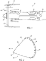
- FIG. 1 illustrates a schematic diagram of a gas turbine machine 10 utilizing the improvements disclosed herein.
- the turbine machine 10 includes a compressor 12, a combustor 14 and a turbine 16.
- a fan 18 includes a nosecone assembly 20, blade members 22 and a fan casing 24.
- the blade members 22 direct low pressure air to a bypass flow path 26 and to the compressor intake 28, which in turn provides airflow to compressor 12.
- the nosecone assembly 20 generates turbulent airflow, which in turn is directed across the surface of the blade member 22.
- Figure 2 illustrates a perspective view of the nosecone assembly 20 that is depicted in Fig. 1 .
- the nosecone 20 could be made of a variety of composite materials including, but not limited to, filament-wound threads that collectively form a parabolic-shaped structure having a smooth exterior finished aerodynamic surface.
- the nosecone assembly 20 includes a body 30 having a leading point 32 and a trailing edge 34.
- An aerodynamic profile with an exterior surface 36 extends between the leading point 32 and the trailing edge 34.
- the trailing edge 34 has a periphery 38 for receiving a plurality of aerodynamic fairings 40 that are spaced about the periphery 38 at equal distances extending therebetween.
- each fairing 40 is positioned to the rear edge of the nosecone body 30 for aiding in providing smooth transitional laminar airflow to a leading edge of the blade member 22. More, or fewer, fairings 40 can be employed, and they can be positioned differently.
- FIG. 3 illustrates an enlarged side elevational view of the nosecone assembly 20.
- Each fairing 40 is shown secured to the exterior surface of the aerodynamic profile 36 and they are equally spaced around the periphery 38 so as to provide uniform balanced operation when under power.
- the underside of each fairing 40 has a contoured attachment surface 66 ( Fig. 5 ) that mirrors the corresponding surface on the aerodynamic profile 36 to which it is received.
- a smooth gap-free interface is present between the transition area of the fairing 40 and the aerodynamic profile 36.
- the blade member 22 includes a leading edge 48 that is adjacent to each of the fairings 40.
- the blade member 22 further includes a plurality of blades 46, each of which having their own leading edge 48.
- a transition zone 50 is defined by the fairing 40 and the leading edge 48, which in this example, aerodynamic flow in the transition zone 50 is improved so as to improve specific fuel consumption. This is due in part to the fairings 40 directing airflow around the leading edge 48.
- Each fairing 40 may be secured to the aerodynamic profile 36 by various methods.
- fairing 40 may be chemically secured to the exterior profile of the nosecone by using adhesives.
- the fairing 40 (as shown in Fig. 3 ) may be mechanically fastened or otherwise secured to the exterior surface 36 of the nosecone body 30 through the use of a mechanical attachment feature such as, but not limited to, pins, pegs, bolts, slots, and other mechanical methodologies and devices.
- a mechanical attachment feature such as, but not limited to, pins, pegs, bolts, slots, and other mechanical methodologies and devices.
- other methods of securing the fairings 40 to the nosecone body 30 are contemplated, including methods and devices that permit the fairing 40 to be removably replaced with other fairings 40.
- the fairing 40 can be interchangeable.
- Figure 4 illustrates a partial side-sectional view taken from circle four of figure 3 , illustrating one fairing of 40 shown mounted on the body 30 of the nosecone assembly 20.
- a leading edge 48 of the blade member 22 is shown slightly offset from the trailing edge 34 of the nosecone body 30.
- a gap 52 may extend between the trailing edge 34 of the nosecone assembly 20 and the leading edge 48. It is preferable to minimize the gap 52 so as to enhance aerodynamic laminar flow in the transition zone 50.
- a seal 54 extends from the fairing 40 and into the gap 52 to provide a much smaller transitional or minimal gap 56.
- the pads 72 can touch the blades 46. Therefore, gap 56 may not, and perhaps should not, exist.
- the minimal gap 56 can be so minimal that an aerodynamic seal 54 is created between the fairing 40 and the hub 42 so as to improve air flow around the leading edge 48.
- the rear surface 58 of the fairing 40 is lined up flush with the trailing edge of 34 of the nosecone body 30.
- FIG. 5 illustrates an exemplary fairing 40 and its constituent components.
- fairing 40 could have other ornamental or aerodynamic configurations and it could also be referred to as a 3-D aerodynamic structure, bump, deflector, or the like.
- the fairing 40 has a base 60, a cavity 62, a surface coating 64 and an attachment surface 66.
- the base includes a profiled surface 68 which, it will be appreciated, can be comprised of other surface configurations apart from that depicted in this exemplary illustration.
- the base 60 further includes a rear surface 58 that is substantially planer which leads into cavity 62.
- the attachment surface 66 is non-linear and it substantially matches the parabolic curvature of the aerodynamic profile 36 of the nosecone body 30.
- the attachment surface 66 can include an adhesive material 70 for creating a frictional bond between the fairing 40' and the aerodynamic profile 36 of the nosecone body 30.
- the base 60 is constructed to be sufficiently ridged to be impact resistant and may be made of composite, metallic, plastic or other similar type materials.
- the fairing 40 further includes a filler material, or pad 72, which could be made of an elastomer, organic material composite, or other similar type materials.
- the pad 72 extends substantially within the cavity 62 and is rigidly secured to the cavity 62 mechanically, chemically, or by other methods.
- the pad 72 includes a first portion 74 that extends axially substantially within the cavity 62, and a second portion 76 protruding from the cavity.
- the second portion 76 has a substantially planer face 78 with a large cross sectional area for enhancing laminar air flow to the leading edge 48.
- An offset portion 80 of the pad 72 extends past the rear surface 58 of the base 60 a preferred distance to reduce the gap 52 that extends between the nosecone trailing edge 34 and the leading edge 48 of the blade member.
- the offset portion 80 acts as a seal 54 ( Fig.4 ) to minimize the gap 56 in the transition zone 50.
- the cavity 62 may be partially filled by the pad 72.
- other materials could be positioned within the cavity 62, apart from the pad 72.
- the cavity 62 may extend across a substantial width of the rear surface 58 and may extend axially along axis X-X a depth of the base 60. The depth could extend near the tip or the end 84 (see Fig. 6 ) of the base or the depth could be only partially into the base 60.
- the surface coating 64 extends over substantially the entire contoured profile surface 68 of the fairing 40.
- the surface coating 64 provides an outer skin over the surface 68 and is made preferably of paint.
- the thickness of the coating 64 may be approximately 1 mm, and has a low coefficient of friction.
- Figure 6 illustrates a top view of the figure 5 fairing 40.
- the pad 72 is shown located partially within the cavity 62.
- An axis X-X extends along the length of the fairing 40 and the cavity 62 may extend along axis X-X a substantial distance along the axis.
- FIGs 7 and 8 illustrate an alternative fairing assembly of 40', which includes many of the same features and components as discussed in the figure 5 embodiment. Thus, where possible, like numbers and references are provided and will not be repeated in this discussion.
- the alternative fairing assembly of 40' has protruding and extending from the attachment surface 66 an attachment feature 90 extending substantially perpendicular to the attachment surface 66.
- Each attachment feature 90 has a perpendicularly extending member 92 with a first diameter 94 and an enlarged second diameter 96.
- a slot 98 extends axially a substantial distance within the member 92, which in turn allows the outwardly extending tip 100 to be collapsible when under load. It will be appreciated that two attachment features 90 are shown in connection with the alternative fairing 40'. However, a single, or a plurality of attachment features 90 may be employed.
- the features 90 may be integrated with the base 60 or they can be a separate component, but either way, they are preferably rigidly secured so that the body 60 and features 90 perform as a rigid unitary assembly. It is possible that the body 60 and the features 90 could be molded as one integral assembly.
- Each attachment feature 90 is designed to fit within mounting apertures 102 that appear in the aerodynamic profile surface 36 of the nosecone assembly 20. ( Fig. 3 ).
- an alternative fairing 40' is shown rigidly secured to the lower portion of exterior profile 36 by inserting each attachment feature 90 into its corresponding hole 102.
- a tab 104 extends around the perimeter of the second diameter 96 and creates a locking feature 106 whereby the fairing 40' snaps into place and thus, is rigidly secured to the body 30 of the nosecone 20.
- the fairing 40' could be dissembled from the body 30 by reaching inside the nosecone body 30 and compressing the tip 100 so as to allow for the attachment feature 90 to be disengaged from the mounting holes 102.
- the fairing 40' is detachable and may be replaced with yet different fairings, if so desired.
- a modifiable nosecone assembly 20 is presented which, in one instance may have a fairing 40' with a certain profile, but then later can be modified to have a fairing 40' with a different profile.
- the nosecone 20, therefore, is reconfigurable.
- a composite aerodynamic nosecone will be provided having a leading edge portion and a trailing edge portion with a contoured surface extending between the edge portions.
- an aerodynamic fairing will be provided, the fairing having a base with a profiled surface, an attachment surface and a cavity.
- the fairing further has a pad with a first portion that is located within the cavity and a second portion that is located outside of the cavity which creates an over flush type arrangement.
- the next step is to attach at least one aerodynamic fairing to the nosecone.
- the fairing may be attached near the trailing edge of the nosecone such that the second portion of the pad extends beyond the trailing edge of the nosecone. This improved assembly operates to provide a seal between the pad and the hub 42.
Landscapes
- Engineering & Computer Science (AREA)
- Chemical & Material Sciences (AREA)
- Combustion & Propulsion (AREA)
- Mechanical Engineering (AREA)
- General Engineering & Computer Science (AREA)
- Aviation & Aerospace Engineering (AREA)
- Structures Of Non-Positive Displacement Pumps (AREA)
Description
- This application claims priority to
U.S. Provisional Patent Application No. 61/776,563 filed March 11, 2013 U.S. Utility Patent Application No. 14/035,571 filed September 24, 2013 , the contents of which are hereby incorporated in their entirety. - An improved nosecone assembly for a gas turbine engine is disclosed, and more particularly, an improved composite nosecone component having secondarily attached aerodynamic fairing features that are attached to a surface of the nosecone component.
- It has become increasingly desirable to provide a 3-D nosecone or spinner that is made of woven composite material, which in turn provides a structurally sound component for a gas turbine engine that is light weight and highly durable. Composite material nosecones provide significant weight advantages over traditional metal nosecone constructs which are typically more expensive due to the rising cost of aerospace materials and the high cost of manufacturing.
- A gas turbine engine's performance is influenced in part by the aerodynamic flow across the surface of the nosecone as well as by the shape of the fan blades that are positioned adjacent to the trailing edge of the nosecone. The surface of the nosecone may be modified so as to improve performance. However, modifying only the surface of the nosecone has limited benefits and are insufficient to reach the level of enhanced aerodynamic performance that is demanded by the industry.
- Specific fuel consumption of a gas turbine engine can be improved if the air flow transitioning from the nosecone to the leading edge of the fan blade is kept as much as possible in a laminar state of flow. Thus, it would be desirable to provide enhanced laminar airflow in a transition zone between the trailing edge of the nosecone and the fan blades in the hub region. This could be accomplished by providing an aerodynamic member on the trailing edge of the nosecone. The problem, however, is that it is difficult to construct a composite nosecone that also includes integral or even separate aerodynamic features for directing the airflow around the blade leading edge of a fan. It would be desirable to overcome this problem and provide a device that enhances air flow around the blade leading edge, which may be blunt and thus, may generate turbulent air flow.
EP 2 096 029 A2 discloses a prior art fan nosecone. - While the claims are not limited to a specific illustration, an appreciation of the various aspects is best gained through a discussion of various examples thereof Referring now to the drawings, exemplary illustrations are shown in detail. Although the drawings represent the illustrations, the drawings are not necessarily to scale and certain features may be exaggerated to better illustrate and explain an innovative aspect of an example. Further, the exemplary illustrations described herein are not intended to be exhaustive or otherwise limiting or restricted to the precise form and configuration shown in the drawings and disclosed in the following detailed description. Exemplary illustrations are described in detail by referring to the drawings as follows:
-
FIG. 1 illustrates a side schematic view of a gas turbine engine employing the improvements discussed herein; -
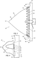
FIG. 2 illustrates a perspective view of a nosecone with aerodynamic fairings that are attached around a perimeter of the trailing edge of the nosecone; -
FIG. 3 illustrates an enlarged side-elevational view of theFig. 2 device, showing the fairings attached to the nosecone; -
FIG. 4 illustrates an enlarged partial side sectional view taken fromcircle 4 ofFIG. 3 , showing a fairing and the transition zone leading to a blade member; -
FIG. 5 illustrates a perspective view of a fairing member that is shown in theFig. 3 device; -
FIG. 6 illustrates a top view of theFIG. 5 fairing member; -
FIG. 7 illustrates an alternative fairing member, showing its attachment features which engage openings in the surface of a nosecone; and -
FIG. 8 is a top view of theFIG. 7 fairing member. - Exemplary illustrations of a nosecone assembly having a composite body with fairings secured to the composite body are described herein and are shown in the attached drawings. Exemplary nosecone assemblies may include a one-piece aerodynamic fan nosecone assembly having a fan nosecone composite body with a leading edge and a trailing edge. The nosecone assembly may also have an aerodynamic exterior surface that extends between the leading edge and the trailing edge. One or more aerodynamic fairings or bumps may be affixed to the exterior surface of the nosecone.
- Another exemplary illustration includes providing a method of manufacturing a spinner component which may include an aerodynamic nosecone having a parabolic surface extending from a tip of the nosecone to a rear edge of the nosecone. The method of manufacturing may further include the step of providing at least one aerodynamic fairing which has a base with a profiled surface, an attachment surface and a cavity. The fairing may further have a filler material with a first portion that is located within the cavity and a second portion that is located outside of the cavity. The method of manufacturing could also include the step of attaching at least one fairing to the nosecone at a location near the rear edge of the nosecone such that the second portion of the filler material extends beyond the rear edge of the nosecone to form a seal between the nosecone and the leading edge. Other aspects of the disclosure will become apparent and are set forth below.
- Turning now to the drawings,
Figure 1 illustrates a schematic diagram of agas turbine machine 10 utilizing the improvements disclosed herein. Theturbine machine 10 includes acompressor 12, acombustor 14 and aturbine 16. A fan 18 includes anosecone assembly 20,blade members 22 and afan casing 24. Theblade members 22 direct low pressure air to abypass flow path 26 and to the compressor intake 28, which in turn provides airflow tocompressor 12. Thenosecone assembly 20 generates turbulent airflow, which in turn is directed across the surface of theblade member 22. -
Figure 2 illustrates a perspective view of thenosecone assembly 20 that is depicted inFig. 1 . It will be appreciated that thenosecone 20 could be made of a variety of composite materials including, but not limited to, filament-wound threads that collectively form a parabolic-shaped structure having a smooth exterior finished aerodynamic surface. Thenosecone assembly 20 includes abody 30 having a leadingpoint 32 and atrailing edge 34. An aerodynamic profile with anexterior surface 36 extends between the leadingpoint 32 and thetrailing edge 34. Thetrailing edge 34 has aperiphery 38 for receiving a plurality ofaerodynamic fairings 40 that are spaced about theperiphery 38 at equal distances extending therebetween. In the example provided, approximately twenty aerodynamic fairings are equally spaced around theperiphery 38 of thenosecone body 30. Eachfairing 40 is positioned to the rear edge of thenosecone body 30 for aiding in providing smooth transitional laminar airflow to a leading edge of theblade member 22. More, or fewer,fairings 40 can be employed, and they can be positioned differently. -
Figure 3 illustrates an enlarged side elevational view of thenosecone assembly 20. Eachfairing 40 is shown secured to the exterior surface of theaerodynamic profile 36 and they are equally spaced around theperiphery 38 so as to provide uniform balanced operation when under power. The underside of eachfairing 40 has a contoured attachment surface 66 (Fig. 5 ) that mirrors the corresponding surface on theaerodynamic profile 36 to which it is received. Thus, a smooth gap-free interface is present between the transition area of thefairing 40 and theaerodynamic profile 36. - The
blade member 22 includes a leadingedge 48 that is adjacent to each of thefairings 40. Theblade member 22 further includes a plurality ofblades 46, each of which having their own leadingedge 48. Atransition zone 50 is defined by thefairing 40 and the leadingedge 48, which in this example, aerodynamic flow in thetransition zone 50 is improved so as to improve specific fuel consumption. This is due in part to thefairings 40 directing airflow around the leadingedge 48. - Each
fairing 40 may be secured to theaerodynamic profile 36 by various methods. For example,fairing 40 may be chemically secured to the exterior profile of the nosecone by using adhesives. Alternatively the fairing 40 (as shown inFig. 3 ) may be mechanically fastened or otherwise secured to theexterior surface 36 of thenosecone body 30 through the use of a mechanical attachment feature such as, but not limited to, pins, pegs, bolts, slots, and other mechanical methodologies and devices. It will be appreciated that other methods of securing thefairings 40 to thenosecone body 30 are contemplated, including methods and devices that permit thefairing 40 to be removably replaced withother fairings 40. Thus, the fairing 40 can be interchangeable. -
Figure 4 illustrates a partial side-sectional view taken from circle four offigure 3 , illustrating one fairing of 40 shown mounted on thebody 30 of thenosecone assembly 20. A leadingedge 48 of theblade member 22 is shown slightly offset from the trailingedge 34 of thenosecone body 30. Agap 52 may extend between the trailingedge 34 of thenosecone assembly 20 and the leadingedge 48. It is preferable to minimize thegap 52 so as to enhance aerodynamic laminar flow in thetransition zone 50. Aseal 54 extends from the fairing 40 and into thegap 52 to provide a much smaller transitional orminimal gap 56. Thepads 72 can touch theblades 46. Therefore,gap 56 may not, and perhaps should not, exist. Theminimal gap 56 can be so minimal that anaerodynamic seal 54 is created between the fairing 40 and thehub 42 so as to improve air flow around the leadingedge 48. Therear surface 58 of the fairing 40 is lined up flush with the trailing edge of 34 of thenosecone body 30. -
Figure 5 illustrates anexemplary fairing 40 and its constituent components. It will be appreciated that fairing 40 could have other ornamental or aerodynamic configurations and it could also be referred to as a 3-D aerodynamic structure, bump, deflector, or the like. The fairing 40 has abase 60, acavity 62, asurface coating 64 and anattachment surface 66. The base includes a profiledsurface 68 which, it will be appreciated, can be comprised of other surface configurations apart from that depicted in this exemplary illustration. The base 60 further includes arear surface 58 that is substantially planer which leads intocavity 62. Theattachment surface 66 is non-linear and it substantially matches the parabolic curvature of theaerodynamic profile 36 of thenosecone body 30. Theattachment surface 66 can include anadhesive material 70 for creating a frictional bond between the fairing 40' and theaerodynamic profile 36 of thenosecone body 30. Thebase 60 is constructed to be sufficiently ridged to be impact resistant and may be made of composite, metallic, plastic or other similar type materials. - The fairing 40 further includes a filler material, or
pad 72, which could be made of an elastomer, organic material composite, or other similar type materials. Thepad 72 extends substantially within thecavity 62 and is rigidly secured to thecavity 62 mechanically, chemically, or by other methods. Thepad 72 includes afirst portion 74 that extends axially substantially within thecavity 62, and asecond portion 76 protruding from the cavity. Thesecond portion 76 has a substantiallyplaner face 78 with a large cross sectional area for enhancing laminar air flow to the leadingedge 48. An offsetportion 80 of thepad 72 extends past therear surface 58 of the base 60 a preferred distance to reduce thegap 52 that extends between thenosecone trailing edge 34 and the leadingedge 48 of the blade member. The offsetportion 80 acts as a seal 54 (Fig.4 ) to minimize thegap 56 in thetransition zone 50. - It will be appreciated that the
cavity 62 may be partially filled by thepad 72. For example, other materials could be positioned within thecavity 62, apart from thepad 72. Also, thecavity 62 may extend across a substantial width of therear surface 58 and may extend axially along axis X-X a depth of thebase 60. The depth could extend near the tip or the end 84 (seeFig. 6 ) of the base or the depth could be only partially into thebase 60. - The
surface coating 64 extends over substantially the entirecontoured profile surface 68 of thefairing 40. Thesurface coating 64 provides an outer skin over thesurface 68 and is made preferably of paint. The thickness of thecoating 64 may be approximately 1 mm, and has a low coefficient of friction. -
Figure 6 illustrates a top view of thefigure 5 fairing 40. Thepad 72 is shown located partially within thecavity 62. An axis X-X extends along the length of the fairing 40 and thecavity 62 may extend along axis X-X a substantial distance along the axis. -
Figures 7 and 8 illustrate an alternative fairing assembly of 40', which includes many of the same features and components as discussed in thefigure 5 embodiment. Thus, where possible, like numbers and references are provided and will not be repeated in this discussion. - The alternative fairing assembly of 40' has protruding and extending from the
attachment surface 66 anattachment feature 90 extending substantially perpendicular to theattachment surface 66. Eachattachment feature 90 has aperpendicularly extending member 92 with afirst diameter 94 and an enlargedsecond diameter 96. Aslot 98 extends axially a substantial distance within themember 92, which in turn allows the outwardly extendingtip 100 to be collapsible when under load. It will be appreciated that two attachment features 90 are shown in connection with the alternative fairing 40'. However, a single, or a plurality of attachment features 90 may be employed. Thefeatures 90 may be integrated with the base 60 or they can be a separate component, but either way, they are preferably rigidly secured so that thebody 60 and features 90 perform as a rigid unitary assembly. It is possible that thebody 60 and thefeatures 90 could be molded as one integral assembly. - Each
attachment feature 90 is designed to fit within mountingapertures 102 that appear in theaerodynamic profile surface 36 of thenosecone assembly 20. (Fig. 3 ). Here, an alternative fairing 40' is shown rigidly secured to the lower portion ofexterior profile 36 by inserting eachattachment feature 90 into itscorresponding hole 102. Atab 104 extends around the perimeter of thesecond diameter 96 and creates alocking feature 106 whereby the fairing 40' snaps into place and thus, is rigidly secured to thebody 30 of thenosecone 20. - The fairing 40' could be dissembled from the
body 30 by reaching inside thenosecone body 30 and compressing thetip 100 so as to allow for theattachment feature 90 to be disengaged from the mounting holes 102. Thus, the fairing 40' is detachable and may be replaced with yet different fairings, if so desired. Accordingly, amodifiable nosecone assembly 20 is presented which, in one instance may have a fairing 40' with a certain profile, but then later can be modified to have a fairing 40' with a different profile. Thenosecone 20, therefore, is reconfigurable. - A method of manufacturing a nosecone will now be described. First, a composite aerodynamic nosecone will be provided having a leading edge portion and a trailing edge portion with a contoured surface extending between the edge portions. Next, an aerodynamic fairing will be provided, the fairing having a base with a profiled surface, an attachment surface and a cavity. The fairing further has a pad with a first portion that is located within the cavity and a second portion that is located outside of the cavity which creates an over flush type arrangement. The next step is to attach at least one aerodynamic fairing to the nosecone. The fairing may be attached near the trailing edge of the nosecone such that the second portion of the pad extends beyond the trailing edge of the nosecone. This improved assembly operates to provide a seal between the pad and the
hub 42. - Even though the present disclosure has been described in detail with reference to specific embodiments, it will be appreciated that the various modification and changes can be made to these embodiments without departing from the scope of the present disclosure as set forth in the claims. The specification and the drawings are to be regarded as an illustrative thought instead of merely restrictive thought.
Claims (14)
- A one-piece aerodynamic fan nosecone assembly (20) comprising:a fan nosecone (30) having a leading edge (32) and a trailing edge (34) with an aerodynamic exterior surface (36) extending between the leading and trailing edge (32, 34);a plurality of aerodynamic fairings (40, 40') spaced apart and affixed to said aerodynamic exterior surface (36) of the fan nosecone (30); said fairings (40, 40') having a base (60) with a profiled surface (68), an attachment surface (66) and a cavity (62), the fairings (40, 40') further having a filler material (72) with a first portion (74) that is located within the cavity (62) and a second portion (76) that is located outside of the cavity (62); andan attachment feature (90) extending downwardly from a lower portion (66) of each fairing (40, 40').
- The nosecone assembly (20) according to claim 1, further comprising a mechanical connection between the fan nosecone (30) and at least one fairing (40, 40').
- The nosecone assembly (20) according to any one of claims 1 or 2, wherein said attachment feature (90) includes, a pair of male members (90) extending downwardly from the lower portion (66) of each fairing (40, 40'), each said male member (90) having a locking feature (104, 106) for securing the fairing (40, 40') to the surface (36) of the fan nosecone (30).
- The nosecone assembly (20) according to any one of claims 1 to 3, further comprising a chemical bond (70) connecting at least one fairing (40, 40') to the fan nosecone (30).
- The nosecone assembly (20) according to any one of claims 1 to 4, wherein the fairings (40, 40') includes:the base (60) having an aerodynamic portion (68),a surface coating (64) extending over a portion (68) of the base (60), an insert (72), andthe attachment feature (70, 90) that mounts an underside (66) of the base (60) to the fan nosecone (30).
- The nosecone assembly (20) according to claim 5, wherein the base (30) includes the cavity (62) that is sized to receive a portion (74, 76) of the insert (72).
- The nosecone assembly (20) according to any one of claims 5 to 6, wherein the insert (72) is made of filler material and has a portion (72, 74, 80) that projects from the base (60), the portion (72, 74, 80) projecting from the base (60) enhances aerodynamic sealing between the fan nosecone (30) and a blade member (22).
- The nosecone assembly (20) according to any of the preceding claims, further comprising a seal (54) that is formed as part of the fairing (40), the seal (54) is located between the fan nosecone (30) and a blade member (22) that is located approximate to the fan nosecone (30).
- The nosecone assembly (20) according to any of the preceding claims, wherein the plurality of fairings (40, 40') are equally spaced apart from one another around a periphery (38) of the fan nosecone (30).
- A method of manufacturing a nosecone component (20) comprising the steps of:providing an aerodynamic nosecone (30) having a leading edge portion (32) and a trailing edge portion (34), a contoured surface (36) extending between the edge portions (32, 34);providing at least one aerodynamic fairing (40, 40'), said fairing (40, 40') having a base (60) with a profiled surface (68), an attachment surface (66) and a cavity (62), the fairing (40, 40') further having a filler material (72) with a first portion (74) that is located within the cavity (62) and a second portion (76) that is located outside of the cavity (62), further having an attachment feature (90) extending downwardly from the attachment surface (66) of each fairing (40, 40'); andattaching at least one aerodynamic fairing (40, 40') to the nosecone (30) at a location near the trailing edge portion (34) such that the second portion (76) of the filler material (72) extends beyond the trailing edge (34) of the nosecone (30).
- The method according to claim 10, further comprising providing a hole (102) in the contoured surface (36) of the nosecone (30) and providing said attachment feature (90) on the base (60), inserting the attachment feature (90) of the base (60) into the hole (102) in the contoured surface (36) of the nosecone (30).
- The method according to any one of claims 10 to 11, wherein the step of attaching at least one aerodynamic fairing (40, 40') includes chemically bonding (70) the fairing (40, 40') to the nosecone (30).
- The method according to any one of claims 10 to 12, wherein the step of attaching at least one aerodynamic fairing (40, 40') includes mechanically connecting (90) the fairing (40, 40') to the nosecone (30).
- The method according to any of claims 10 to 13, wherein the step of attaching at least one aerodynamic fairing (40, 40') to the nosecone (30) results in a minimal gap (52, 56) between the second portion (76) of the filler material (72) and a leading edge (48) of a blade member (22) to direct laminar air flow around the leading edge (48) of a blade member (22).
Applications Claiming Priority (3)
| Application Number | Priority Date | Filing Date | Title |
|---|---|---|---|
| US201361776563P | 2013-03-11 | 2013-03-11 | |
| US14/035,571 US9481448B2 (en) | 2013-03-11 | 2013-09-24 | Aerodynamic fairings secondarily attached to nosecone |
| PCT/US2013/066486 WO2014143190A1 (en) | 2013-03-11 | 2013-10-24 | Aerodynamic fairings secondarily attached to nosecone |
Publications (2)
| Publication Number | Publication Date |
|---|---|
| EP2971515A1 EP2971515A1 (en) | 2016-01-20 |
| EP2971515B1 true EP2971515B1 (en) | 2018-04-11 |
Family
ID=51488036
Family Applications (1)
| Application Number | Title | Priority Date | Filing Date |
|---|---|---|---|
| EP13786386.6A Not-in-force EP2971515B1 (en) | 2013-03-11 | 2013-10-24 | Aerodynamic fairings secondarily attached to nosecone |
Country Status (3)
| Country | Link |
|---|---|
| US (1) | US9481448B2 (en) |
| EP (1) | EP2971515B1 (en) |
| WO (1) | WO2014143190A1 (en) |
Families Citing this family (11)
| Publication number | Priority date | Publication date | Assignee | Title |
|---|---|---|---|---|
| US10100644B2 (en) | 2014-03-03 | 2018-10-16 | Rolls-Royce Corporation | Spinner for a gas turbine engine |
| US11035340B2 (en) | 2014-08-05 | 2021-06-15 | Biomerenewables Inc. | Fluidic turbine structure |
| US10794197B2 (en) | 2017-06-15 | 2020-10-06 | General Electric Company | Coated turbine component and method for forming a component |
| US10746031B2 (en) | 2017-07-18 | 2020-08-18 | Rolls-Royce Corporation | Annulus filler |
| US11078839B2 (en) * | 2018-01-22 | 2021-08-03 | Rolls-Royce Corporation | Composite nosecone |
| CN109630273B (en) * | 2018-11-23 | 2021-04-16 | 中国航发沈阳黎明航空发动机有限责任公司 | An aero-engine fairing cap based on the Magnus effect |
| FR3097256B1 (en) * | 2019-06-14 | 2021-05-21 | Safran Aircraft Engines | INPUT CONE FOR AN AIRCRAFT TURBOMACHINE |
| US11421538B2 (en) | 2020-05-12 | 2022-08-23 | Rolls-Royce Corporation | Composite aerofoils |
| US11506083B2 (en) | 2020-06-03 | 2022-11-22 | Rolls-Royce Corporalion | Composite liners for turbofan engines |
| US12326162B2 (en) * | 2022-06-03 | 2025-06-10 | Hamilton Sundstrand Corporation | Integrated radial diffuser with movable diffuser hub |
| US12516626B1 (en) | 2025-05-09 | 2026-01-06 | Rtx Corporation | Fan blade assembly with leading edge fillet |
Family Cites Families (15)
| Publication number | Priority date | Publication date | Assignee | Title |
|---|---|---|---|---|
| US3508842A (en) | 1968-10-08 | 1970-04-28 | Trane Co | Apparatus for improving axial velocity profile of axial flow fans |
| US4256435A (en) | 1978-08-02 | 1981-03-17 | Eckel Oliver C | Mounting support blocks for pivotal rotor of wind turbine |
| US4931026A (en) | 1989-04-24 | 1990-06-05 | Woodland Sylvester L | Jet propeller |
| GB9018457D0 (en) | 1990-08-22 | 1990-10-03 | Rolls Royce Plc | Flow control means |
| US5833435A (en) | 1996-12-24 | 1998-11-10 | United Technologies Corporation | Inlet nose cone assembly and method for repairing the assembly |
| US5800121A (en) | 1997-03-26 | 1998-09-01 | Fanelli; August J. | Pneumatic electric generating system |
| US6358014B1 (en) | 2000-03-24 | 2002-03-19 | General Electric Company | Composite spinner and method of making the same |
| GB2364748A (en) | 2000-07-15 | 2002-02-06 | Rolls Royce Plc | Gas turbine engine nose cone with tool access hole plug/cover |
| US7048505B2 (en) * | 2002-06-21 | 2006-05-23 | Darko Segota | Method and system for regulating fluid flow over an airfoil or a hydrofoil |
| FR2873751B1 (en) | 2004-07-28 | 2006-09-29 | Snecma Moteurs Sa | INPUT CONE OF A TURBOMACHINE |
| DE102006011513A1 (en) | 2006-03-10 | 2007-09-13 | Rolls-Royce Deutschland Ltd & Co Kg | Inlet cone of a fiber composite material for a gas turbine engine and method for its production |
| US7721526B2 (en) * | 2006-06-28 | 2010-05-25 | Ishikawajima-Harima Heavy Industries Co., Ltd. | Turbofan engine |
| GB0803366D0 (en) | 2008-02-26 | 2008-04-02 | Rolls Royce Plc | Nose cone assembly |
| DE102008035160A1 (en) | 2008-07-28 | 2010-02-04 | Rolls-Royce Deutschland Ltd & Co Kg | Method for improving the flow conditions on the propeller or fan of an aircraft engine and then trained hub cone |
| US20140186166A1 (en) * | 2012-12-27 | 2014-07-03 | General Electric Company | Hybrid Continuous Fiber Chopped Fiber Polymer Composite Structure |
-
2013
- 2013-09-24 US US14/035,571 patent/US9481448B2/en not_active Expired - Fee Related
- 2013-10-24 EP EP13786386.6A patent/EP2971515B1/en not_active Not-in-force
- 2013-10-24 WO PCT/US2013/066486 patent/WO2014143190A1/en not_active Ceased
Also Published As
| Publication number | Publication date |
|---|---|
| EP2971515A1 (en) | 2016-01-20 |
| US20140255204A1 (en) | 2014-09-11 |
| WO2014143190A1 (en) | 2014-09-18 |
| US9481448B2 (en) | 2016-11-01 |
Similar Documents
| Publication | Publication Date | Title |
|---|---|---|
| US9481448B2 (en) | Aerodynamic fairings secondarily attached to nosecone | |
| US9957972B2 (en) | Airfoil with an integrally stiffened composite cover | |
| JP6579871B2 (en) | How to install nacelle structure to minimize fatigue load | |
| US8366039B2 (en) | Fairing for a pylon via which a turbine engine is suspended from a wing of an aircraft | |
| RU2620482C1 (en) | Composite shoulder | |
| US11131314B2 (en) | Fan blade with structural spar and integrated leading edge | |
| EP2562361B1 (en) | Structural composite fan exit guide vane for a turbomachine | |
| EP2346736B1 (en) | Integrated inlet design | |
| EP2811143B1 (en) | Fan rotor blade of aircraft jet engine | |
| US10823190B2 (en) | Fan blade with variable thickness composite cover | |
| US10557361B1 (en) | Platform for an airfoil of a gas turbine engine | |
| US11136888B2 (en) | Rotor assembly with active damping for gas turbine engines | |
| US20160177732A1 (en) | Hollow fan blade for a gas turbine engine | |
| CN102748204A (en) | Spoiler for a wind turbine blade | |
| US20040000613A1 (en) | Preforms for acute structural edges | |
| US20140271143A1 (en) | Fan Spacer Having Unitary Over Molded Feature | |
| US20160215789A1 (en) | Fan blade assembly | |
| CN103080476B (en) | Turbojet engine blade, in particular a guide blade, and turbojet engine receiving such blades | |
| US20230304407A1 (en) | Airfoil with body and cover panel | |
| US20110219782A1 (en) | Aerodynamically shaped supporting and/or fairing element in the bypass duct of a gas-turbine engine | |
| WO2015041083A1 (en) | Seal for turbofan engine | |
| US20170023006A1 (en) | Fan blade with composite cover and structural filler | |
| US20200123914A1 (en) | Hybrid airfoil for gas turbine engines | |
| US10330112B2 (en) | Fan blade with root through holes | |
| Zhan et al. | An aerodynamic and aeroelastic integrated design |
Legal Events
| Date | Code | Title | Description |
|---|---|---|---|
| PUAI | Public reference made under article 153(3) epc to a published international application that has entered the european phase |
Free format text: ORIGINAL CODE: 0009012 |
|
| 17P | Request for examination filed |
Effective date: 20151009 |
|
| AK | Designated contracting states |
Kind code of ref document: A1 Designated state(s): AL AT BE BG CH CY CZ DE DK EE ES FI FR GB GR HR HU IE IS IT LI LT LU LV MC MK MT NL NO PL PT RO RS SE SI SK SM TR |
|
| AX | Request for extension of the european patent |
Extension state: BA ME |
|
| RIN1 | Information on inventor provided before grant (corrected) |
Inventor name: TOTTEN, TREVOR, JOHN Inventor name: RIVERS, JONATHAN, MICHAEL Inventor name: ENGEBRETSEN, ERIC, WILLIAM |
|
| RIN1 | Information on inventor provided before grant (corrected) |
Inventor name: TOTTEN, TREVOR, JOHN Inventor name: ENGEBRETSEN, ERIC, WILLIAM Inventor name: RIVERS, JONATHAN, MICHAEL |
|
| DAX | Request for extension of the european patent (deleted) | ||
| 17Q | First examination report despatched |
Effective date: 20170127 |
|
| REG | Reference to a national code |
Ref country code: DE Ref legal event code: R079 Ref document number: 602013035805 Country of ref document: DE Free format text: PREVIOUS MAIN CLASS: F01D0005060000 Ipc: F02K0003060000 |
|
| GRAP | Despatch of communication of intention to grant a patent |
Free format text: ORIGINAL CODE: EPIDOSNIGR1 |
|
| RIC1 | Information provided on ipc code assigned before grant |
Ipc: F02K 3/06 20060101AFI20171128BHEP |
|
| INTG | Intention to grant announced |
Effective date: 20171220 |
|
| GRAS | Grant fee paid |
Free format text: ORIGINAL CODE: EPIDOSNIGR3 |
|
| GRAA | (expected) grant |
Free format text: ORIGINAL CODE: 0009210 |
|
| AK | Designated contracting states |
Kind code of ref document: B1 Designated state(s): AL AT BE BG CH CY CZ DE DK EE ES FI FR GB GR HR HU IE IS IT LI LT LU LV MC MK MT NL NO PL PT RO RS SE SI SK SM TR |
|
| REG | Reference to a national code |
Ref country code: GB Ref legal event code: FG4D |
|
| REG | Reference to a national code |
Ref country code: CH Ref legal event code: EP |
|
| REG | Reference to a national code |
Ref country code: AT Ref legal event code: REF Ref document number: 988293 Country of ref document: AT Kind code of ref document: T Effective date: 20180415 |
|
| REG | Reference to a national code |
Ref country code: IE Ref legal event code: FG4D |
|
| REG | Reference to a national code |
Ref country code: DE Ref legal event code: R096 Ref document number: 602013035805 Country of ref document: DE |
|
| REG | Reference to a national code |
Ref country code: NL Ref legal event code: MP Effective date: 20180411 |
|
| REG | Reference to a national code |
Ref country code: LT Ref legal event code: MG4D |
|
| PG25 | Lapsed in a contracting state [announced via postgrant information from national office to epo] |
Ref country code: NL Free format text: LAPSE BECAUSE OF FAILURE TO SUBMIT A TRANSLATION OF THE DESCRIPTION OR TO PAY THE FEE WITHIN THE PRESCRIBED TIME-LIMIT Effective date: 20180411 |
|
| REG | Reference to a national code |
Ref country code: FR Ref legal event code: PLFP Year of fee payment: 6 |
|
| PG25 | Lapsed in a contracting state [announced via postgrant information from national office to epo] |
Ref country code: BG Free format text: LAPSE BECAUSE OF FAILURE TO SUBMIT A TRANSLATION OF THE DESCRIPTION OR TO PAY THE FEE WITHIN THE PRESCRIBED TIME-LIMIT Effective date: 20180711 Ref country code: FI Free format text: LAPSE BECAUSE OF FAILURE TO SUBMIT A TRANSLATION OF THE DESCRIPTION OR TO PAY THE FEE WITHIN THE PRESCRIBED TIME-LIMIT Effective date: 20180411 Ref country code: PL Free format text: LAPSE BECAUSE OF FAILURE TO SUBMIT A TRANSLATION OF THE DESCRIPTION OR TO PAY THE FEE WITHIN THE PRESCRIBED TIME-LIMIT Effective date: 20180411 Ref country code: AL Free format text: LAPSE BECAUSE OF FAILURE TO SUBMIT A TRANSLATION OF THE DESCRIPTION OR TO PAY THE FEE WITHIN THE PRESCRIBED TIME-LIMIT Effective date: 20180411 Ref country code: NO Free format text: LAPSE BECAUSE OF FAILURE TO SUBMIT A TRANSLATION OF THE DESCRIPTION OR TO PAY THE FEE WITHIN THE PRESCRIBED TIME-LIMIT Effective date: 20180711 Ref country code: SE Free format text: LAPSE BECAUSE OF FAILURE TO SUBMIT A TRANSLATION OF THE DESCRIPTION OR TO PAY THE FEE WITHIN THE PRESCRIBED TIME-LIMIT Effective date: 20180411 Ref country code: ES Free format text: LAPSE BECAUSE OF FAILURE TO SUBMIT A TRANSLATION OF THE DESCRIPTION OR TO PAY THE FEE WITHIN THE PRESCRIBED TIME-LIMIT Effective date: 20180411 Ref country code: LT Free format text: LAPSE BECAUSE OF FAILURE TO SUBMIT A TRANSLATION OF THE DESCRIPTION OR TO PAY THE FEE WITHIN THE PRESCRIBED TIME-LIMIT Effective date: 20180411 |
|
| PG25 | Lapsed in a contracting state [announced via postgrant information from national office to epo] |
Ref country code: RS Free format text: LAPSE BECAUSE OF FAILURE TO SUBMIT A TRANSLATION OF THE DESCRIPTION OR TO PAY THE FEE WITHIN THE PRESCRIBED TIME-LIMIT Effective date: 20180411 Ref country code: HR Free format text: LAPSE BECAUSE OF FAILURE TO SUBMIT A TRANSLATION OF THE DESCRIPTION OR TO PAY THE FEE WITHIN THE PRESCRIBED TIME-LIMIT Effective date: 20180411 Ref country code: GR Free format text: LAPSE BECAUSE OF FAILURE TO SUBMIT A TRANSLATION OF THE DESCRIPTION OR TO PAY THE FEE WITHIN THE PRESCRIBED TIME-LIMIT Effective date: 20180712 Ref country code: LV Free format text: LAPSE BECAUSE OF FAILURE TO SUBMIT A TRANSLATION OF THE DESCRIPTION OR TO PAY THE FEE WITHIN THE PRESCRIBED TIME-LIMIT Effective date: 20180411 |
|
| REG | Reference to a national code |
Ref country code: AT Ref legal event code: MK05 Ref document number: 988293 Country of ref document: AT Kind code of ref document: T Effective date: 20180411 |
|
| PG25 | Lapsed in a contracting state [announced via postgrant information from national office to epo] |
Ref country code: PT Free format text: LAPSE BECAUSE OF FAILURE TO SUBMIT A TRANSLATION OF THE DESCRIPTION OR TO PAY THE FEE WITHIN THE PRESCRIBED TIME-LIMIT Effective date: 20180813 |
|
| REG | Reference to a national code |
Ref country code: DE Ref legal event code: R097 Ref document number: 602013035805 Country of ref document: DE |
|
| PG25 | Lapsed in a contracting state [announced via postgrant information from national office to epo] |
Ref country code: EE Free format text: LAPSE BECAUSE OF FAILURE TO SUBMIT A TRANSLATION OF THE DESCRIPTION OR TO PAY THE FEE WITHIN THE PRESCRIBED TIME-LIMIT Effective date: 20180411 Ref country code: SK Free format text: LAPSE BECAUSE OF FAILURE TO SUBMIT A TRANSLATION OF THE DESCRIPTION OR TO PAY THE FEE WITHIN THE PRESCRIBED TIME-LIMIT Effective date: 20180411 Ref country code: AT Free format text: LAPSE BECAUSE OF FAILURE TO SUBMIT A TRANSLATION OF THE DESCRIPTION OR TO PAY THE FEE WITHIN THE PRESCRIBED TIME-LIMIT Effective date: 20180411 Ref country code: DK Free format text: LAPSE BECAUSE OF FAILURE TO SUBMIT A TRANSLATION OF THE DESCRIPTION OR TO PAY THE FEE WITHIN THE PRESCRIBED TIME-LIMIT Effective date: 20180411 Ref country code: CZ Free format text: LAPSE BECAUSE OF FAILURE TO SUBMIT A TRANSLATION OF THE DESCRIPTION OR TO PAY THE FEE WITHIN THE PRESCRIBED TIME-LIMIT Effective date: 20180411 Ref country code: RO Free format text: LAPSE BECAUSE OF FAILURE TO SUBMIT A TRANSLATION OF THE DESCRIPTION OR TO PAY THE FEE WITHIN THE PRESCRIBED TIME-LIMIT Effective date: 20180411 |
|
| PLBE | No opposition filed within time limit |
Free format text: ORIGINAL CODE: 0009261 |
|
| STAA | Information on the status of an ep patent application or granted ep patent |
Free format text: STATUS: NO OPPOSITION FILED WITHIN TIME LIMIT |
|
| PG25 | Lapsed in a contracting state [announced via postgrant information from national office to epo] |
Ref country code: SM Free format text: LAPSE BECAUSE OF FAILURE TO SUBMIT A TRANSLATION OF THE DESCRIPTION OR TO PAY THE FEE WITHIN THE PRESCRIBED TIME-LIMIT Effective date: 20180411 Ref country code: IT Free format text: LAPSE BECAUSE OF FAILURE TO SUBMIT A TRANSLATION OF THE DESCRIPTION OR TO PAY THE FEE WITHIN THE PRESCRIBED TIME-LIMIT Effective date: 20180411 |
|
| 26N | No opposition filed |
Effective date: 20190114 |
|
| PG25 | Lapsed in a contracting state [announced via postgrant information from national office to epo] |
Ref country code: SI Free format text: LAPSE BECAUSE OF FAILURE TO SUBMIT A TRANSLATION OF THE DESCRIPTION OR TO PAY THE FEE WITHIN THE PRESCRIBED TIME-LIMIT Effective date: 20180411 |
|
| REG | Reference to a national code |
Ref country code: CH Ref legal event code: PL |
|
| GBPC | Gb: european patent ceased through non-payment of renewal fee |
Effective date: 20181024 |
|
| REG | Reference to a national code |
Ref country code: BE Ref legal event code: MM Effective date: 20181031 |
|
| PG25 | Lapsed in a contracting state [announced via postgrant information from national office to epo] |
Ref country code: LU Free format text: LAPSE BECAUSE OF NON-PAYMENT OF DUE FEES Effective date: 20181024 Ref country code: MC Free format text: LAPSE BECAUSE OF FAILURE TO SUBMIT A TRANSLATION OF THE DESCRIPTION OR TO PAY THE FEE WITHIN THE PRESCRIBED TIME-LIMIT Effective date: 20180411 |
|
| REG | Reference to a national code |
Ref country code: IE Ref legal event code: MM4A |
|
| PG25 | Lapsed in a contracting state [announced via postgrant information from national office to epo] |
Ref country code: CH Free format text: LAPSE BECAUSE OF NON-PAYMENT OF DUE FEES Effective date: 20181031 Ref country code: BE Free format text: LAPSE BECAUSE OF NON-PAYMENT OF DUE FEES Effective date: 20181031 Ref country code: LI Free format text: LAPSE BECAUSE OF NON-PAYMENT OF DUE FEES Effective date: 20181031 |
|
| PG25 | Lapsed in a contracting state [announced via postgrant information from national office to epo] |
Ref country code: GB Free format text: LAPSE BECAUSE OF NON-PAYMENT OF DUE FEES Effective date: 20181024 Ref country code: IE Free format text: LAPSE BECAUSE OF NON-PAYMENT OF DUE FEES Effective date: 20181024 |
|
| PG25 | Lapsed in a contracting state [announced via postgrant information from national office to epo] |
Ref country code: MT Free format text: LAPSE BECAUSE OF NON-PAYMENT OF DUE FEES Effective date: 20181024 |
|
| PG25 | Lapsed in a contracting state [announced via postgrant information from national office to epo] |
Ref country code: TR Free format text: LAPSE BECAUSE OF FAILURE TO SUBMIT A TRANSLATION OF THE DESCRIPTION OR TO PAY THE FEE WITHIN THE PRESCRIBED TIME-LIMIT Effective date: 20180411 |
|
| PG25 | Lapsed in a contracting state [announced via postgrant information from national office to epo] |
Ref country code: HU Free format text: LAPSE BECAUSE OF FAILURE TO SUBMIT A TRANSLATION OF THE DESCRIPTION OR TO PAY THE FEE WITHIN THE PRESCRIBED TIME-LIMIT; INVALID AB INITIO Effective date: 20131024 Ref country code: CY Free format text: LAPSE BECAUSE OF FAILURE TO SUBMIT A TRANSLATION OF THE DESCRIPTION OR TO PAY THE FEE WITHIN THE PRESCRIBED TIME-LIMIT Effective date: 20180411 Ref country code: MK Free format text: LAPSE BECAUSE OF NON-PAYMENT OF DUE FEES Effective date: 20180411 |
|
| PG25 | Lapsed in a contracting state [announced via postgrant information from national office to epo] |
Ref country code: IS Free format text: LAPSE BECAUSE OF FAILURE TO SUBMIT A TRANSLATION OF THE DESCRIPTION OR TO PAY THE FEE WITHIN THE PRESCRIBED TIME-LIMIT Effective date: 20180811 |
|
| P01 | Opt-out of the competence of the unified patent court (upc) registered |
Effective date: 20230528 |
|
| PGFP | Annual fee paid to national office [announced via postgrant information from national office to epo] |
Ref country code: FR Payment date: 20231026 Year of fee payment: 11 Ref country code: DE Payment date: 20231027 Year of fee payment: 11 |
|
| REG | Reference to a national code |
Ref country code: DE Ref legal event code: R119 Ref document number: 602013035805 Country of ref document: DE |
|
| PG25 | Lapsed in a contracting state [announced via postgrant information from national office to epo] |
Ref country code: DE Free format text: LAPSE BECAUSE OF NON-PAYMENT OF DUE FEES Effective date: 20250501 |
|
| PG25 | Lapsed in a contracting state [announced via postgrant information from national office to epo] |
Ref country code: FR Free format text: LAPSE BECAUSE OF NON-PAYMENT OF DUE FEES Effective date: 20241031 |