EP2971359B1 - Portable porous construction mat system - Google Patents
Portable porous construction mat system Download PDFInfo
- Publication number
- EP2971359B1 EP2971359B1 EP14711896.2A EP14711896A EP2971359B1 EP 2971359 B1 EP2971359 B1 EP 2971359B1 EP 14711896 A EP14711896 A EP 14711896A EP 2971359 B1 EP2971359 B1 EP 2971359B1
- Authority
- EP
- European Patent Office
- Prior art keywords
- tabs
- porous unit
- mat
- ground
- mat system
- Prior art date
- Legal status (The legal status is an assumption and is not a legal conclusion. Google has not performed a legal analysis and makes no representation as to the accuracy of the status listed.)
- Active
Links
Images













Classifications
-
- E—FIXED CONSTRUCTIONS
- E01—CONSTRUCTION OF ROADS, RAILWAYS, OR BRIDGES
- E01C—CONSTRUCTION OF, OR SURFACES FOR, ROADS, SPORTS GROUNDS, OR THE LIKE; MACHINES OR AUXILIARY TOOLS FOR CONSTRUCTION OR REPAIR
- E01C5/00—Pavings made of prefabricated single units
-
- E—FIXED CONSTRUCTIONS
- E01—CONSTRUCTION OF ROADS, RAILWAYS, OR BRIDGES
- E01C—CONSTRUCTION OF, OR SURFACES FOR, ROADS, SPORTS GROUNDS, OR THE LIKE; MACHINES OR AUXILIARY TOOLS FOR CONSTRUCTION OR REPAIR
- E01C5/00—Pavings made of prefabricated single units
- E01C5/005—Individual couplings or spacer elements for joining the prefabricated units
-
- E—FIXED CONSTRUCTIONS
- E01—CONSTRUCTION OF ROADS, RAILWAYS, OR BRIDGES
- E01C—CONSTRUCTION OF, OR SURFACES FOR, ROADS, SPORTS GROUNDS, OR THE LIKE; MACHINES OR AUXILIARY TOOLS FOR CONSTRUCTION OR REPAIR
- E01C5/00—Pavings made of prefabricated single units
- E01C5/20—Pavings made of prefabricated single units made of units of plastics, e.g. concrete with plastics, linoleum
-
- E—FIXED CONSTRUCTIONS
- E01—CONSTRUCTION OF ROADS, RAILWAYS, OR BRIDGES
- E01C—CONSTRUCTION OF, OR SURFACES FOR, ROADS, SPORTS GROUNDS, OR THE LIKE; MACHINES OR AUXILIARY TOOLS FOR CONSTRUCTION OR REPAIR
- E01C9/00—Special pavings; Pavings for special parts of roads or airfields
- E01C9/08—Temporary pavings
-
- E—FIXED CONSTRUCTIONS
- E01—CONSTRUCTION OF ROADS, RAILWAYS, OR BRIDGES
- E01C—CONSTRUCTION OF, OR SURFACES FOR, ROADS, SPORTS GROUNDS, OR THE LIKE; MACHINES OR AUXILIARY TOOLS FOR CONSTRUCTION OR REPAIR
- E01C9/00—Special pavings; Pavings for special parts of roads or airfields
- E01C9/08—Temporary pavings
- E01C9/086—Temporary pavings made of concrete, wood, bitumen, rubber or synthetic material or a combination thereof
-
- E—FIXED CONSTRUCTIONS
- E01—CONSTRUCTION OF ROADS, RAILWAYS, OR BRIDGES
- E01C—CONSTRUCTION OF, OR SURFACES FOR, ROADS, SPORTS GROUNDS, OR THE LIKE; MACHINES OR AUXILIARY TOOLS FOR CONSTRUCTION OR REPAIR
- E01C2201/00—Paving elements
- E01C2201/12—Paving elements vertically interlocking
Definitions
- This disclosure relates to mats for use in portable porous construction systems, the systems utilizing the mats, methods for assembly and use, and tools useful for assembling and disassembling the systems.
- US 2012/243949 relates to an anchor arrangement for use with an open mat system, as well as to an open mat system and to methods for reinforcing earth.
- US 2008/072514 relates to an interlocking floor system.
- a portable construction mat system comprises a mat which in turn comprises a porous unit having an outer perimeter and a matrix of intersecting walls defining a plurality of cells within the perimeter, the cells having a through hole therethrough.
- the porous unit When the mat is in an installed condition, the porous unit has a mounting side facing ground, and a user side opposite the mounting side, each of the cells in the plurality of cells including a drainage aperture arrangement.
- the portable construction mat system also comprises a ground anchor constructed and arranged to be oriented through a first one of the cells to secure the mat to the ground.
- a plurality of first and second tabs are projecting from the porous unit along the perimeter, each of the first and second tabs including an aperture therein to allow releasable fastening thereto.
- the ground anchor comprises a solid rod, said rod having an insertion end for insertion in the ground and an opposite end having a washer secured thereto.
- the washer is configured and adapted to lie atop the mounting side of the first one of the cells when the rod is inserted through the through hole into the ground.
- FIG. 1 illustrates a portable porous construction mat system generally at 20.
- the system 20 includes a grid 22, depicted schematically in FIG. 1 , made from a plurality of individual construction mats 24 ( FIG. 2 ) secured or connected together at connection points 26 ( FIG. 8 ).
- a truck 28 is illustrated driving on the grid 22.
- the grid 22 is oriented on a surface 30, which will typically be earth, including soil or ground 31. In many typical applications, it will be desirable to transport heavy equipment into an area that does not have roads or stable soil.
- a plurality of the construction mats 24 are assembled together to form grid 22 and secured together by the connection points 26. In such systems, the grid 22 is quickly and easily assembled. The grid 22 also is able to be quickly and easily disassembled.
- FIG. 2 shows one example construction mat 24 usable in the system 20.
- the mat 24 is portable in that it is of a size that can be easily stacked onto pallets and moved.
- each mat 24 is sized about 102 cm by 51 cm (40 inches by 20 inches), with a thickness of about 5cm (2 inches).
- other sizes are usable.
- the mat 24 is a porous unit 25, in that it has ample through holes to allow for drainage throughout the mat 24.
- the mat 24 has an outer perimeter 32 and a matrix of intersecting walls 34 defining a plurality of cells 36 within the perimeter 32.
- each of the cells 36 includes a drainage aperture arrangement 38 therein, this drainage aperture arrangement 38 is in the form of a through hole 40.
- the mat 24, in the embodiment illustrated, includes a double wall structure 42 (see FIG. 4 ) framing the mat 24 and extending between the outer perimeter 32 and the matrix of cells 36.
- This double wall structure 42 helps with strength and integrity for the mat 24.
- Each of the mats 24 has a mounting side 44 and an opposite user side 46.
- the mounting side 44 is the side that is in contact with the ground surface 30 ( FIG. 1 ).
- the user side 46 is the side that is open to the surrounding environment and is the side that is exposed to the heavy equipment, such as truck 28 ( FIG. 1 ). In FIG. 2 , the user side 46 is the side that is in view.
- FIG. 3 shows the mounting side 44.
- Each of the cells 36 defined by the walls 34 includes the drainage aperture 38, which is depicted as a rectangular hole 40.
- the holes 40 are defined by an axial surface 48, including a user side axial surface 49 ( FIG. 4 ) and the mounting side axial surface 50 ( FIG. 3 ). Extending approximately perpendicular from the user side axial surface 49 are the walls 34. In the example shown, the walls 34 form approximate rectangles, in which free ends 52 ( FIGS. 2 and 5 ) define and form the user side 46.
- each of the mats 24, in typical example embodiments, will have at least 20 cells 36, typically 30-50 cells 36, and in the example shown, 40 cells 36.
- the mat 24 comprises a molded non-metal material. Usable materials include a molded thermoplastic.
- Each of the mats 24 has a weight of not greater than 9 kg (20 lbs.), typically 4 - 7 kg (9-15 lbs.).
- Each mat 24 will have a crush strength of at least 0.7 MPa ( 100 PSI) and flexural modulus of 690 MPa to 1379 MPa (100,000 to 200,000 PSI).
- the open area of the user side 46 is typically 75 -95%.
- the open area of the mounting side 44 is typically 25 -35%.
- the mat 24 includes a plurality of first and second tabs 56, 58.
- the first and second tabs 56, 58 each project from a remainder of the porous unit of the mat 24 and along the perimeter 32.
- the first tab 56 and second tab 58 are useful in connecting more than one mat 24 together to form grid 22.
- Each of the first tabs 56 is recessed from the user side 46 and even with the mounting side 50.
- the first tab 56 includes an aperture 60 constructed and arranged to allow releasable fastening thereto, to be described further below.
- Each of the second tabs 58 is recessed from the mounting side 44 and even with the user side 46.
- Each of the second tabs 58 includes an aperture 62 constructed and arranged allow releasable fastening thereto, to be described further below.
- the mat 24 has a first pair of opposite sides 64, 65 and a second pair of opposite sides 66, 67.
- first tabs 56 and at least two of the second tabs 58 are along the perimeter 32 of each of the sides 64, 65 of the first pair of sides. In other embodiments, there can be more than two of the first tabs 56 and more than two of the second tabs 58 along each of the sides 64, 65.
- At least one of the first tabs 56 and at least one of the second tabs 58 is along the perimeter 32 of each of the sides 66, 67 of the second pair. In other embodiments, there can be more than one of the first tabs 56 and more than one of the second tabs 58 along the sides 66, 67.
- first and second tabs 56, 58 alternate sequentially along each of the first pair of sides 64, 65 and along each of the second pair of sides 66, 67.
- the porous unit 25 has a two-fold axis of symmetry about a central longitudinal axis 70 ( FIG. 4 ).
- a central longitudinal axis 70 FIG. 4
- alternate embodiments are possible.
- each of the apertures 62 of the second tab 58 is a fastener-receiving aperture 62.
- the aperture 62 is an elongated non-circular opening 72. This elongated opening 72 builds in tolerance for when the mats 52 are aligned next to each other and connected together to form grid 22.
- the apertures 60, 62 in the first and second tabs 56, 58 need not be in precise alignment to be connected to each other.
- the apertures 62 could be circular, or other shapes.
- each of the apertures 60 of the first tabs 56 is a fastener-receiving aperture 60.
- the aperture 60 includes a pair of opposing generally semi-circular surfaces 74, 75 (see FIG. 3A ) defining the hole or aperture 60 constructed to receive a fastener.
- the semi-circular surfaces 74, 75 are separated by a pair of opposite guide slots 152, 153, which are discussed further below.
- the fastener for the first tab apertures 60 is a nut 78 ( FIGS. 8 and 11-14 ).
- the apertures 60 can have threads of nut 78 molded in place.
- aperture 60 receiving a separate nut 78, as illustrated; or aperture 60 have pre-molded threads therein acting as a nut
- the aperture 60 allows releasable fastening thereto, and is interchangeably referred to herein as "aperture 60" or "fastener-receiving aperture 60.”
- the mats 24 can be arranged relative to each other and connected together to form the grid 22.
- the mats 24 are connected together in a staggered pattern in the form of a running bond pattern 80 ( FIGS. 6 and 7 ).
- running bond it is meant each mat 24 is laid as a stretcher overlapping the mats 24 in the adjoining courses.
- a first porous unit is shown at reference number 82
- a second porous unit is shown at reference numeral 84.
- the second porous unit 84 is oriented laterally adjacent to and against the first porous unit 82.
- one of the first tabs 56 of the second porous unit 84 is oriented under one of the second tabs 58 of the first porous unit 82 to define a first connection 86.
- One of the second tabs 58 of the second porous unit 84 is oriented over one of the first tabs 56 of the first porous unit 82 to define a second connection 88.
- the first connection 86 will include a fastener arrangement 87 ( FIG. 8 ) to be held within the fastener-receiving apertures 60, 62 of the first and second tabs 56, 58 of the first connection 86.
- the second connection 88 will include fastener arrangement 87 ( FIG. 8 ) to be held within the fastener-receiving apertures 60, 62 of the respective first and second tabs 56, 58 of the second connection 88.
- the first and second connections 86, 88 show only a portion of the fastener arrangement 87 (nut 78) therein, ready to receive the other portion of the fastener arrangement (bolt 112).
- the mat system 20 further includes at least a third porous unit 92 laterally adjacent to and against the first porous unit 82.
- One of the first tabs 56 of the third porous unit 92 is oriented under one of the second tabs 58 of the first porous unit 82 to define a third connection 94 attached by a fastener arrangement 87.
- One of the second tabs 58 of the third porous unit 92 is oriented over one of the first tabs 56 of the first porous unit 82 to define a fourth connection 96 attached by fastener arrangement 87.
- first connection 86, second connection 88, third connection 94, and fourth connection 96 are all along a single side 64 ( FIG. 6 ) of the first porous unit 82.
- the second porous unit 84 and the third porous unit 92 are connected together at a fifth connection 100 and sixth connection 102 along sides 66, 67 of the second porous unit 84 and third porous unit 92 that are generally perpendicular to the single side 64 of the first porous unit 82.
- the fifth connection 100 includes one of the first tabs 56 of the third porous unit 92 being oriented under one of the second tabs 58 of the second porous unit 84 and attached by fastener arrangement 87.
- the sixth connection 102 includes one of the second tabs 58 of the third porous unit 92 being oriented over one of the first tabs 56 of the second porous unit 84 and attached by fastener arrangement 87.
- the system 20 also includes at least a fourth porous unit 106 and a fifth porous unit 108.
- the fourth porous unit 106 is connected to the third porous unit 92 along side 64 of the third porous unit 92, opposite of side 65 that is connected to the first porous unit 82.
- the fifth porous unit 108 is shown connected to both the third porous unit 92 and the second porous unit 84.
- the fifth porous unit 108 is connected to side 64 of units 92 and 84, opposite of the sides 65 of third unit 92 and second unit 84 that are connected to the first porous unit 82.
- the fourth porous unit 106 and fifth porous unit 108 are also connected to each other along sides 67 of the fourth porous unit 106and 66 of the fifth porous unit 108.
- each of the porous units 82, 84, 92, 106, 108 has first tabs 56 alternating sequentially with second tabs 58. There are no first tabs 56 together, without being separated by a second tab 58; similarly, there are no second tabs 58 together without being separated by a first tab 56.
- first connection 96, second connection 88, third connection 94, fourth connection 96, fifth connection 100, and sixth connection 102 include fastener arrangement 87 ( FIG. 8 ) connecting together the respective first and second tabs 56, 58 of each connection 86, 88, 94, 100, 102.
- fastener arrangement 87 includes nut 78 and bolt 112.
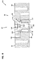
- FIG. 8 illustrates the connection 100, but it should be understood that each connection 86, 88, 94, and 102 will be constructed analogously.
- the nut 78 is a split nut 114 ( FIGS. 11-14 ).
- the split nut 114 can be made from a molded non-metal material.
- the molded non-metal material is made from the same material as the porous units 25, such as a molded thermoplastic.
- the split nut 114 is made of a stronger material than the porous units 25, such as nylon with glass reinforcement. This stronger material can be helpful if a stronger connection is needed between the tabs 56, 58.
- the split nut 114 includes first and second halves 116, 117.
- the halves 116, 117 are fitable together to form integral nut 78 having a generally tapered and circular outer cross-section.
- half nut 116 includes an inner surface 118 with threads 120.
- Half nut 117 includes an inner surface 119 with threads 121.
- the threads 120, 121 are for engaging the bolt 112.
- the first half 116 of the split nut 114 has a first side 122, second side 123, and an arched extension 124 therebetween.
- the first side 122 includes a projection 126 extending therefrom.
- the projection 126 is spaced from both a top rim 127 and bottom rim 128.
- the second side 123 includes a recess 130, spaced from both the top rim 127 and bottom rim 128.
- the arched extension 124 includes inner surface 118, as mentioned previously, which is threaded 120.
- An exterior surface 132 of the arched extension 124 includes a projecting rail 134.
- the rail 134 in the embodiment shown, is centered between the first side 122 and second side 123.
- the second half 117 of the split nut 114 is constructed to mate with the first half 116 and result in nut 78 that has a threaded socket 136 ( FIG. 11 ) to engage the bolt 112.
- the second half 117 includes first side 138, second side 139, and arched extension 140 extending therebetween.
- the first side 138 includes a projection 142
- the second side 139 includes a recess 144.
- the projection 142 and recess 144 are spaced from the top rim 145 and bottom rim 146.
- the exterior surface 148 of the arched extension 140 includes rail 150 extending there from.
- the projection 126 of the first half 116 is received within the recess 144 of the second half 117.
- the projection 142 of the second half 117 is received by the recess 130 of the first half 116.
- the nut 78 fits within the apertures 60 of the first tabs 56.
- the aperture 60 in the first tab 56 includes opposite guide slots 152, 153 ( FIG. 3A ).
- the guide slots 152, 153 receive the rails 134, 150 of the halves 116, 117 of the split nut 114.
- the slots 152, 153, in combination with the rails 134, 150 hold the split nut 114 in place in the aperture 60 of the first tab 56.
- the threads can be molded as part of the aperture 60, in which case, no separate nut 78 will need to be positioned in the aperture 60, but in such cases the aperture 60 is still considered an aperture constructed and arranged to allow releasable fastening thereto, and a "fastener-receiving aperture 60.”
- the nut 78 is of a color that will be visually distinct from the color of the porous unit 25.
- the nut 78 can be yellow, while the porous unit 25 is black. This visually distinct color will help the user installing the mat system 20 to not miss any connections that need to be made between the various porous units 25.
- the bolt 112 is also part of the fastener arrangement 87.
- One example usable bolt 112 is illustrated in FIGS. 9 and 10 .
- the bolt 112 can be made from a molded non-metal material. This material can be the same as the material made from the split nut 114, or it may be a different material.
- the material for the bolt 112 can be the same material as used for the porous units 25, such as a molded thermoplastic, or it may be made from a material stronger than the porous unit 25, such as nylon with glass reinforcement.
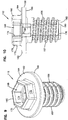
- the bolt 112 includes a shaft 156, a flange 158, and a head 160.
- the shaft 156 is threaded with threads 157 that engages with the threaded socket 136 formed by the nut 78.
- the flange 158 has a diameter that is wider than the diameter of the shaft 156 and narrower than an outermost dimension of the head 160.
- the flange 158 acts as a washer 162.
- the washer 162 has an upper axial surface 164 and a lower axial surface 165 on an opposite side as the upper axial surface 164.
- the lower axial surface 165 engages against a flange-receiving surface 166 of the second tab 58 surrounding the second tab aperture 62.
- the bolt 112 includes a socket 168.
- the socket 168 is defined by a head wall 170, having an outer polygon surface 172 and an inner polygon surface 174.
- the inner polygon surface 174 lines the socket 168.
- the socket 168 is adapted to receive a torqueing tool 176 ( FIGS. 15-20 ). The tool 176 is discussed further below.
- the head wall 170 can have many different shapes.
- the outer polygon surface 172 is a hexagon shape.
- the inner polygon surface 174 is a hexagon shape.
- the bolt 112 can also include a through hole 178.
- the through hole 178 extends completely through the bolt 112 from the head 160, through the flange 158 and through the shaft 156, such that the bolt 112 has an opening 180 ( FIGS. 8 and 10 ) at an end 182 of the bolt 112.
- at least a portion of the through hole 178 has an inner polygon surface 184 lining the through hole 178.
- the inner polygon surface 184 is shaped and adapted to receive a torqueing tool.
- the bolts 112 can be of a different color from the color of the porous units 25.
- the bolts 112 will be of a color contrasting to the color of the porous units 25.
- the bolts 112 can be yellow, while the porous units 25 are black. This helps the user identify all of the connection points more easily.
- At least some of the bolts 112 can include a location device 188 ( FIG. 22 and 23 ), such as an RFID tag or a GPS tag secured thereto. This can provide location information electronically of the connection holding the bolt 112.
- a location device 188 FIG. 22 and 23
- This can provide location information electronically of the connection holding the bolt 112.
- ground stake 190 ( FIG. 22 ) disposed through the through hole 178 of one of the bolts 112.
- the ground stake 190 can help anchor the porous unit 25 to the ground.
- ground delineators 192 FIG. 23 disposed through the through hole 178 of one of the bolts 112. These can be used, for example, to identify the outside borders of the overall mat system 20.
- the bolts 112 may also have fluorescence or reflectivity additives in the molded material, when making, to result in increasing the visibility of the bolts 112.
- bolts 112 that are put along an edge of grid 22 to mark the edge of a road, or the edge of a perimeter can be bolts 112 that have the fluorescence or reflectivity additives.
- the delineators 192 can also include lights, such solar powered lights, for delineation purposes.
- FIG. 15 illustrates one useable example, embodied as socket wrench 194.
- the socket wrench 194 includes an outer polygonal wall 196.
- the polygonal wall 196 is generally the shape of the head wall 170 of the bolt 112. In the example shown, this is a hexagonal shape.
- An inner surface 197 of the polygonal wall 196 engages the outer polygon surface 172 of the bolt head 160.
- the wrench 194 further includes an Allen wrench 200 mounted inside of the polygonal wall 196.
- the Allen wrench 200 includes an outer wall 202.
- the outer polygonal wall 202 is shaped to have the same geometry as the inner polygonal surface 174 of the bolt head 160.
- the outer polygonal wall 202 is spaced from the inner surface of the polygonal wall 196 to define a socket 204 therebetween.
- FIG. 18 shows the wrench 194 just as it is beginning engagement with the bolt 112.
- FIG. 19 a side view of wrench 194 fully engaged with the bolt 112 is depicted.
- the head wall 170 of the head 160 will be received by the socket 204 of the wrench 194.
- the inner surface 197 of the polygonal wall 196 will engage against the outer polygonal surface 172 of the head wall 170.
- the outer polygonal wall 202 of the Allen wrench 200 will engage against the inner polygonal surface 174 of the head wall 170.
- the tool 176 can then be turned to apply torque between the bolt 112 and the nut 78.
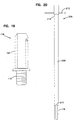
- a driver tool 206 is illustrated.
- the driver tool 206 includes the tool 176 and a handle extension 208 extending from a non-bolt engaging end 210.
- the handle extension 208 can include a cross-bar 212 at or adjacent an end 214 of the handle extension 208 opposite from the end holding the tool 176.
- the cross-bar 212 can include either a full "T" cross-bar 212 (as shown), to accommodate two hands of a worker, or it may include only half a "T" for only a single hand.
- the driver tool 206 can be used by the worker to tighten the bolts 112 within the nuts 78, and without having to crouch, bend over, or work on one's knees. That is, the worker can tighten the bolts 112 in the nuts 78 in a standing position by using the driver tool 206.
- the handle extension 208 will have a height sufficient to accommodate a standing position of an adult human.
- the handle extension 208 could also be adjustable in length.
- FIG. 32 shows another variation on the driver tool 206.
- the impact wrench 211 could be battery powered, pneumatic powered, or electrically powered.
- the impact wrench 211 will secure the bolts 112 by driving the tool 176.
- the bolts 112 will be partially secured with the impact wrench driver tool 206, and then a final tightening can be by hand, with the tool 206 shown in FIG. 20 .
- the bolt 112 can include a tactile feature to sense a "near home" position of the bolt 112 when torqued into position.
- a tactile feature to sense a "near home" position of the bolt 112 when torqued into position.
- FIG. 21 One example is shown in FIG. 21 .
- the bolt flange 158 has a plurality of projections 216 extending from the lower axial surface 165 in a direction toward the threaded shaft 156.
- the second tabs 158 include the flange-receiving surface 166.
- the flange-receiving surface 166 defines a tactile-inducing surface 218 for engaging the projections 216 on the flange 158.
- the tactile-inducing surface 218 includes a plurality of detents 220, such that when the bolt 112 is rotating and being threaded into the socket 136, the lower axial surface 165 of the flange 158 will be rotating relative to the flange-receiving surface 166, and the projections 216 will engage against the detents 220 to produce a tactile sensation, such as a "clicking.”
- the user tightening the bolt 112 into the nut 78 will feel the engagement between the projections 216 and detents 220.
- the user will know after so many "clicks" that the bolt 112 is tightly fastened in the nut 78. This feature will help to ensure the connection points are sufficiently tight.
- the system 20 can be used with ground anchors 224 ( FIGS. 26 and 31 ) to help secure the system 20 to the terrain or earth 31.
- the ground anchor 224 includes a foot 226, which is embedded into the ground 31 ( FIG. 31 ).
- a cable 228 is attached to the foot 226 and extends from the foot 226 through one of the cells 36 ( FIG. 31 ) of the mat 24.
- a washer 230 is mountable against the user side axial surface 49 of the cell 36.
- a cable stop 232 is secured to the cable 228 and oriented against the washer 230.
- the parts of the ground anchor 224 are shown, but not installed in mat 24.
- FIG. 31 there is an example shown of the ground anchor 224 being installed within cell 36 of the mat 24.
- the mat system 20 can include several ground anchors 224 installed in several respective cells 36 to help secure the mat system 20 to the ground 31.
- the washer 230 when operably installed in use, will be inside of cell 36, surrounded by the cell walls 34.
- Ground anchor 224 of FIGS. 26 and 31 can be used along with the ground anchor 225 ( FIG. 33 ) which is foreseen according to the invention.
- Ground anchor 225 includes a solid rod 227 made from, for example, galvanized metal.
- a washer 229 depicted here as rectangular or square, is secured to the rod 227 adjacent an end.
- the washer 229 can be a galvanized metal that is welded to the rod 227.
- the rod 227 can be used as an anchor when the ground conditions, such as frozen ground, prevent driving foots 226 and cables 228 into the ground.
- the rod 227 is 2,5 cm (1 in.) diameter x 61-102 cm (24-40 in.) long; the washer 229 is galvanized square metal 7x7 cm (2-3/4 in. x 2-3/4 in.), which will fit inside of cell 36.
- ground anchor 224 will no longer be tight and positioned to hold the mat 24 in place. In some situations in the prior art, the user would need to apply another, new ground anchor into an adjacent cell. In accordance with principals of this disclosure, however, the user can repair the ground anchor 224 that has become loose.
- the user would pull the cable 228 tight, and move the washer 230 to be against the user side axial surface 49 within the cell 36.
- the cable stop 232 would then be slid over the cable 228 until it was tight against the washer 230. It should be appreciated that, in this condition, the cable stop 232 is within the walls 34 of the cell 36.
- the cable stop 232 will then be slid over the cable 228 until it is tight against the washer 230. It should be appreciated that, in this condition, the cable stop 232 is within the walls 34 of the cell 36.
- FIGS. 24 , 25 , 27, 28 and 31 illustrate a crimper 234 that can be used at an angle of about 10-20°, typically about 15°, relative to the cable 228. In this manner, the crimper 234 can be placed within the walls 34 of the cell 36, and the cable stop 232 can be tightened around the cable 228 within the cell walls 34.
- the crimper 234 constructed in accordance with principals of this disclosure is illustrated.
- the crimper 234 includes first and second crimp jaws 236, 237.
- the jaws 236, 237 are removably mounted within tool 238. As such, the jaws 236, 237 can be removed and replaced in the tool within the field, when needed.
- the jaws 236, 237 are mounted at an angle to the tool 238.
- the crimper is designed to work perpendicular to the cable.
- the crimp jaws 236, 237 are mounted at an angle 242 of 10-20°, typically about 15°, to the tool 238 (see FIG. 25 ).
- the angle 242 is also the approximate angle between the crimp jaws 236, 237 and the cable.
- FIGS. 29 and 30 perspective views of example crimp jaws 236, 237 are illustrated.
- Each of the jaws 236, 237 includes a pair of crimp engaging surfaces 240, 241. This allows the crimper 234 to make a double crimp with one stroke of the tool 238.
- Some example ground anchors 234 will include cable stops 232 that are double in length of a typical one, such that both crimp engaging surfaces 240, 241 will engage and crimp the double length cable stop 232.
- the crimp jaws 236, 237 each include a groove 244 for receiving the tool jaws 246 ( FIGS. 24 , 25 and 28 ) of the tool 238. Fasteners can then be used to attach the crimping jaws 236, 237 to the tool jaws 246 of the tool 238.
- the crimper 234 includes first and second guide screws 248, 249 ( FIGS. 24 and 27 ).
- the guide screws 248, 249 aid in holding the cable 228 in position during the crimping process. In this manner, both hands can be used to handle the crimper 234, and no extra person or hand is needed to hold the cable 228 tight.
- the guide screws 248, 249 help to hold the cable 228 tight and in position during the crimping process. As can be seen in FIG. 27 , the cable 228 extends from the cable stop 232 and between the two guide screws 248, 249.
- the cable stop 232 can include an open side slot 252 ( FIG. 28 ), such that the cable stop 232 can be mounted onto the cable 228 through the slot 252 along the side of the cable stop 232.
- Prior art cable stops typically do not have open side slots, and are threaded onto cables, like stringing beads.
- a kit for constructing mat system 20 can be provided utilizing the materials as described herein.
- One such kit includes at least first and second porous units 25 and a plurality of fastener arrangements 87.
- the fastener arrangements 87 in the kit include a plurality of split nuts 114 and a plurality of threaded bolts 112.
- the kit can include tool 176 to apply a torque force between the bolts 112 and the split nuts 114.
- the kits may also include at least one ground anchor 224.
- the ground anchor will include foot 226, cable 228, washer 230 and cable stop 232.
- the kit can also include at least one crimper 234 to apply force to the cable stop 232 and the cable 228 at an angle of about 10-20° relative to the cable 228.
- a method of providing a construction mat system 20 can be implemented utilizing the materials and principals as described herein.
- a first porous unit such as first porous unit 82 is provided.
- a second porous unit, such as second porous 84 is provided and oriented laterally adjacent to and against the first porous unit 82 and so that one of the second porous unit 84 first tabs 56 is oriented under one of the first porous unit 82 second tabs 58 to define first connection 86.
- One of the second porous unit 84 second tabs 58 is oriented over one of the first porous unit 82 first tabs 56 to define second connection 88.
- the method includes putting fastener arrangement 87 within the fastener-receiving apertures 60, 62 of the respective first and second tabs 56, 58 of the first connection 86.
- the method includes putting fastener arrangement 87 within fastener receiving apertures 60, 62 of the respective first and second tabs 56, 58 of the second connection 88.
- the step of putting fastener arrangement 87 within the fastener-receiving apertures 60, 62 of the first connection 86 includes putting split nut 114 into the fastener-receiving aperture 60 of the first tab 56 of the first connection 86 and putting threaded bolt 112 into the fastener-receiving aperture 62 of the second tab 58 of the first connection 86.
- the bolt can include socket 168, outer polygon surface 172 and inner polygon surface 174 lining the socket 168.
- the method can include using tool 176 to grasp both the outer polygon surface 172 and inner polygon surface 174 to apply a torque force between the bolt 112 and the split nut 114.
- the method can include using bolts 112 having a plurality of projections 216 extending from the flange 158, and wherein the second tabs 58 have flange-receiving surface 166 adjacent to the fastener-receiving apertures 62 of the second tabs 58, so that the flange-receiving surface 166 defines tactile inducing surface 218.
- the step of using tool 176 can include engaging the projections 216 on the flange 158 against the tactile-inducing surface 218 of the flange receiving surface 166.
- the method may further include inserting ground anchor 224 through one of the cells 36 of the first and second porous units 82, 84.
- the ground anchor can include foot 226 embedded into the ground 31; cable 228 attached to the foot 226 and extending from foot 226 through the cell 36; washer 230 against the user side inner axial surface 49 of the walls 34 defining the cell 36; and cable stop 232 secured to the cable 228 and oriented against the washer 230.
- the method can further include crimping the cable stop 232 around the cable 228. This may be done by inserting crimper 234 into the cell 36, grasping the cable stop 232 with the crimper 234, and then tightening the cable stop 232 around the cable 228 using the crimper 234.
- the step of using the crimper 234 can include holding the crimper 234 at an angle of about 10-20°, typically about 15°, relative to the cable 228.
Landscapes
- Engineering & Computer Science (AREA)
- Architecture (AREA)
- Civil Engineering (AREA)
- Structural Engineering (AREA)
- Road Paving Structures (AREA)
- Floor Finish (AREA)
- Pit Excavations, Shoring, Fill Or Stabilisation Of Slopes (AREA)
- Connection Of Plates (AREA)
- Mattresses And Other Support Structures For Chairs And Beds (AREA)
- Carpets (AREA)
- Rehabilitation Tools (AREA)
- Finishing Walls (AREA)
Description
- This application is being filed on 4 March 2014, as a
PCT International patent application, and claims priority to U.S. Patent Application No. 13/796,144 - This disclosure relates to mats for use in portable porous construction systems, the systems utilizing the mats, methods for assembly and use, and tools useful for assembling and disassembling the systems.
- Industries that work in remote locations such as oil, gas, mining, construction, and others can have site access issues requiring improvements such as the construction of roads or work platforms to provide access to and around the site.
- Traditional road and platform construction materials and methods may not be cost effective or environmentally friendly. Alternatives, such as surface mats, are sometimes used. Traditional mat systems, such as mats made from timber or wood, have limitations in that they are expensive, heavy to transport, have a high environmental cost in trees harvested to make the mats, and deteriorate rapidly in use. Polymer and fiber glass mats are large in size and are costly to buy or rent and then transport.
- Still other prior art mat systems can be labor intensive to install and assemble, and likewise can be difficult to disassemble if the mat systems become packed with soil.
- What is needed is a mat system that can be easily disassembled and removed from the site and which is cost effective, easy to transport, and environmentally friendly.
-
US 2012/243949 relates to an anchor arrangement for use with an open mat system, as well as to an open mat system and to methods for reinforcing earth.US 2008/072514 relates to an interlocking floor system. - In one aspect, a portable construction mat system has been provided. The portable construction mat system comprises a mat which in turn comprises a porous unit having an outer perimeter and a matrix of intersecting walls defining a plurality of cells within the perimeter, the cells having a through hole therethrough. When the mat is in an installed condition, the porous unit has a mounting side facing ground, and a user side opposite the mounting side, each of the cells in the plurality of cells including a drainage aperture arrangement. The portable construction mat system also comprises a ground anchor constructed and arranged to be oriented through a first one of the cells to secure the mat to the ground. A plurality of first and second tabs are projecting from the porous unit along the perimeter, each of the first and second tabs including an aperture therein to allow releasable fastening thereto. The ground anchor comprises a solid rod, said rod having an insertion end for insertion in the ground and an opposite end having a washer secured thereto. The washer is configured and adapted to lie atop the mounting side of the first one of the cells when the rod is inserted through the through hole into the ground.
- A variety of examples of desirable product features or methods are set forth in part in the description that follows, and in part will be apparent from the description, or may be learned by practicing various aspects of the disclosure. The aspects of the disclosure may relate to individual features as well as combinations of features. It is to be understood that both the forgoing general description and the following detailed description are explanatory only, and are not restrictive of the claimed invention.
-
-
FIG. 1 is a schematic illustration of a portable porous construction mat system installed and in use, constructed in accordance with principles of this disclosure; -
FIG. 2 is a perspective view of one embodiment of a mat for use in a portable porous construction mat system, constructed in accordance with principles of this disclosure, the view showing a user side of the mat; -
FIG. 3 is another perspective view of the mat ofFIG. 2 showing the mounting side of the mat; -
FIG. 3A is an enlarged perspective view of a portion of the mat ofFIG. 3 , the portion being depicted at 3A inFIG. 3 ; -
FIG. 4 is a top view of the mat ofFIG. 1 ; -
FIG. 5 is a cross-sectional view of the mat ofFIGS. 2-4 , the cross-section being taken along the line 5-5 ofFIG. 4 ; -
FIG. 6 is a perspective view of a portion of a mat system, utilizing the mat ofFIGS. 2-4 connected together; -
FIG. 7 is a top view of the mat system ofFIG. 6 ; -
FIG. 8 is a cross-sectional view showing a connection between two of the mats, the cross-section being taken along the line 8-8 ofFIG. 7 ; -
FIG. 9 is a perspective view of a bolt used in the connection ofFIG. 8 ; -
FIG. 10 is a cross-sectional view of the bolt ofFIG. 9 ; -
FIG. 11 is a perspective view of a split nut used in the connection ofFIG. 8 ; -
FIG. 12 is a top view of the nut ofFIG. 11 ; -
FIG. 13 is a perspective view of a first half of the split nut ofFIG. 11 ; -
FIG. 14 is a perspective view of a second half of the split nut ofFIG. 11 ; -
FIG. 15 is a perspective view of one embodiment of an end of a socket wrench usable with the fasteners for the connection ofFIG. 8 ; -
FIG. 16 is a perspective view of an end of the socket wrench shown inFIG. 15 ; -
FIG. 17 is an end view of the socket wrench ofFIG. 16 ; -
FIG. 18 is a perspective view showing the socket wrench ofFIGS. 15-17 being used with the bolt ofFIG. 9 ; -
FIG. 19 is a side view of the socket wrench ofFIGS. 15-17 inserted onto the bolt ofFIG. 9 ; -
FIG. 20 is a side view of a bolt driver tool with handle used for operating the socket wrench ofFIGS. 15-17 ; -
FIG. 21 is a perspective view of an alternate embodiment of bolt and socket arrangement usable in the connection ofFIG. 8 , the bolt and socket arrangement having a tactile inducing surface; -
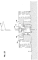
FIG. 22 is a cross-sectional view showing a connection between two of the mats, similar to the cross-section ofFIG. 8 , and showing a ground stake therein; -
FIG. 23 is a cross-sectional view showing a connection between two of the mats, similar to the cross-section ofFIG. 8 , and showing a ground delineator therein; -
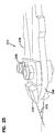
FIG. 24 is top view of one embodiment of a crimper used to secure a ground anchor to the mat system ofFIG. 1 ; -
FIG. 25 is a side view of a portion of the crimper ofFIG. 24 ; -
FIG. 26 is a perspective view of an example ground anchor usable to secure the mat system ofFIG. 1 to the ground; -
FIG. 27 is a perspective view of a portion of the crimper ofFIGS. 24 and25 securing the ground anchor within a cell of the mat ofFIGS. 2-4 ; -
FIG. 28 is another perspective view of a portion of the crimper ofFIGS. 24 and25 securing the ground anchor within a cell of the mat ofFIGS. 2-4 ; -
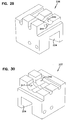
FIG. 29 is a perspective view of one of the crimper jaws used in the crimper ofFIGS. 24 and25 ; -
FIG. 30 is a perspective view of another of the crimper jaws used in the crimper ofFIGS. 24 and25 ; -
FIG. 31 is a schematic perspective view of a step of placing the ground anchor ofFIG. 26 into the ground through a cell of the mat ofFIGS. 2-4 ; -
FIG. 32 is a schematic side view of a variation on the bolt driver tool ofFIG. 20 , this one being shown with an impact wrench; and -
FIG. 33 is a perspective view of another type of ground anchor usable to secure the mat system ofFIG. 1 to the ground. -
FIG. 1 illustrates a portable porous construction mat system generally at 20. Thesystem 20 includes agrid 22, depicted schematically inFIG. 1 , made from a plurality of individual construction mats 24 (FIG. 2 ) secured or connected together at connection points 26 (FIG. 8 ). - In
FIG. 1 , atruck 28 is illustrated driving on thegrid 22. Thegrid 22 is oriented on asurface 30, which will typically be earth, including soil orground 31. In many typical applications, it will be desirable to transport heavy equipment into an area that does not have roads or stable soil. In such applications, a plurality of theconstruction mats 24 are assembled together to formgrid 22 and secured together by the connection points 26. In such systems, thegrid 22 is quickly and easily assembled. Thegrid 22 also is able to be quickly and easily disassembled. -
FIG. 2 shows oneexample construction mat 24 usable in thesystem 20. Themat 24 is portable in that it is of a size that can be easily stacked onto pallets and moved. For example, eachmat 24 is sized about 102 cm by 51 cm (40 inches by 20 inches), with a thickness of about 5cm (2 inches). There is a nominal coverage area of about 0,3 m2 (464 in2). Of course, other sizes are usable. - The
mat 24 is aporous unit 25, in that it has ample through holes to allow for drainage throughout themat 24. Themat 24 has anouter perimeter 32 and a matrix of intersectingwalls 34 defining a plurality ofcells 36 within theperimeter 32. According to the invention, each of thecells 36 includes adrainage aperture arrangement 38 therein, thisdrainage aperture arrangement 38 is in the form of a throughhole 40. - The
mat 24, in the embodiment illustrated, includes a double wall structure 42 (seeFIG. 4 ) framing themat 24 and extending between theouter perimeter 32 and the matrix ofcells 36. Thisdouble wall structure 42 helps with strength and integrity for themat 24. There is an aperture arrangement 43 (FIG. 4 ) between the two walls of thedouble wall structure 42 to assist with drainage. - Each of the
mats 24 has a mountingside 44 and anopposite user side 46. The mountingside 44 is the side that is in contact with the ground surface 30 (FIG. 1 ). Theuser side 46 is the side that is open to the surrounding environment and is the side that is exposed to the heavy equipment, such as truck 28 (FIG. 1 ). InFIG. 2 , theuser side 46 is the side that is in view.FIG. 3 shows the mountingside 44. - Each of the
cells 36 defined by thewalls 34 includes thedrainage aperture 38, which is depicted as arectangular hole 40. Theholes 40 are defined by an axial surface 48, including a user side axial surface 49 (FIG. 4 ) and the mounting side axial surface 50 (FIG. 3 ). Extending approximately perpendicular from the user sideaxial surface 49 are thewalls 34. In the example shown, thewalls 34 form approximate rectangles, in which free ends 52 (FIGS. 2 and5 ) define and form theuser side 46. - Each of the
mats 24, in typical example embodiments, will have at least 20cells 36, typically 30-50cells 36, and in the example shown, 40cells 36. Preferably, themat 24 comprises a molded non-metal material. Usable materials include a molded thermoplastic. Each of themats 24 has a weight of not greater than 9 kg (20 lbs.), typically 4 - 7 kg (9-15 lbs.). Eachmat 24 will have a crush strength of at least 0.7 MPa ( 100 PSI) and flexural modulus of 690 MPa to 1379 MPa (100,000 to 200,000 PSI). The open area of theuser side 46 is typically 75 -95%. The open area of the mountingside 44 is typically 25 -35%. - In accordance with principles of this disclosure, the
mat 24 includes a plurality of first andsecond tabs second tabs mat 24 and along theperimeter 32. Thefirst tab 56 andsecond tab 58 are useful in connecting more than onemat 24 together to formgrid 22. - Each of the
first tabs 56 is recessed from theuser side 46 and even with the mountingside 50. Thefirst tab 56 includes anaperture 60 constructed and arranged to allow releasable fastening thereto, to be described further below. - Each of the
second tabs 58 is recessed from the mountingside 44 and even with theuser side 46. Each of thesecond tabs 58 includes anaperture 62 constructed and arranged allow releasable fastening thereto, to be described further below. - From a review of
FIGS. 2-4 , it can be seen how, in the embodiment illustrated, themat 24 has a first pair ofopposite sides opposite sides first tabs 56 and at least two of thesecond tabs 58 are along theperimeter 32 of each of thesides first tabs 56 and more than two of thesecond tabs 58 along each of thesides - In the illustrated embodiment, at least one of the
first tabs 56 and at least one of thesecond tabs 58 is along theperimeter 32 of each of thesides first tabs 56 and more than one of thesecond tabs 58 along thesides - Many different embodiments can be made. In the example shown, the first and
second tabs sides sides - In this example, the
porous unit 25 has a two-fold axis of symmetry about a central longitudinal axis 70 (FIG. 4 ). Of course, alternate embodiments are possible. - In reference now to
FIG. 4 , it can be seen how, in the illustrated embodiment, each of theapertures 62 of thesecond tab 58 is a fastener-receivingaperture 62. In the example shown, theaperture 62 is an elongatednon-circular opening 72. Thiselongated opening 72 builds in tolerance for when themats 52 are aligned next to each other and connected together to formgrid 22. By having theelongated opening 72, theapertures second tabs apertures 62 could be circular, or other shapes. - In the particular example embodiment shown in the drawings, each of the
apertures 60 of thefirst tabs 56 is a fastener-receivingaperture 60. Theaperture 60, the illustrated embodiment, includes a pair of opposing generallysemi-circular surfaces 74, 75 (seeFIG. 3A ) defining the hole oraperture 60 constructed to receive a fastener. The semi-circular surfaces 74, 75 are separated by a pair ofopposite guide slots first tab apertures 60 is a nut 78 (FIGS. 8 and11-14 ). In other embodiments, theapertures 60 can have threads ofnut 78 molded in place. In both embodiments (aperture 60 receiving aseparate nut 78, as illustrated; oraperture 60 have pre-molded threads therein acting as a nut), theaperture 60 allows releasable fastening thereto, and is interchangeably referred to herein as "aperture 60" or "fastener-receivingaperture 60." - In each of the
tabs apertures drainage apertures 76 to help further facilitate drainage of theporous unit 25. - The
mats 24 can be arranged relative to each other and connected together to form thegrid 22. In preferred embodiments, themats 24 are connected together in a staggered pattern in the form of a running bond pattern 80 (FIGS. 6 and7 ). By "running bond," it is meant eachmat 24 is laid as a stretcher overlapping themats 24 in the adjoining courses. - To form the
mat system 20, and in reference now toFIGS. 6 and7 , a first porous unit is shown atreference number 82, and a second porous unit is shown atreference numeral 84. The secondporous unit 84 is oriented laterally adjacent to and against the firstporous unit 82. To form themat system 20, one of thefirst tabs 56 of the secondporous unit 84 is oriented under one of thesecond tabs 58 of the firstporous unit 82 to define afirst connection 86. One of thesecond tabs 58 of the secondporous unit 84 is oriented over one of thefirst tabs 56 of the firstporous unit 82 to define asecond connection 88. - The
first connection 86 will include a fastener arrangement 87 (FIG. 8 ) to be held within the fastener-receivingapertures second tabs first connection 86. Thesecond connection 88 will include fastener arrangement 87 (FIG. 8 ) to be held within the fastener-receivingapertures second tabs second connection 88. InFIGS. 6 and7 , the first andsecond connections - Still in reference to
FIGS 6 and7 , themat system 20 further includes at least a thirdporous unit 92 laterally adjacent to and against the firstporous unit 82. One of thefirst tabs 56 of the thirdporous unit 92 is oriented under one of thesecond tabs 58 of the firstporous unit 82 to define athird connection 94 attached by afastener arrangement 87. One of thesecond tabs 58 of the thirdporous unit 92 is oriented over one of thefirst tabs 56 of the firstporous unit 82 to define afourth connection 96 attached byfastener arrangement 87. - In the example shown in
FIGS. 6 and7 , thefirst connection 86,second connection 88,third connection 94, andfourth connection 96 are all along a single side 64 (FIG. 6 ) of the firstporous unit 82. - Again, still in reference to
FIGS. 6 and7 , the secondporous unit 84 and the thirdporous unit 92 are connected together at afifth connection 100 andsixth connection 102 alongsides porous unit 84 and thirdporous unit 92 that are generally perpendicular to thesingle side 64 of the firstporous unit 82. Thefifth connection 100 includes one of thefirst tabs 56 of the thirdporous unit 92 being oriented under one of thesecond tabs 58 of the secondporous unit 84 and attached byfastener arrangement 87. Thesixth connection 102 includes one of thesecond tabs 58 of the thirdporous unit 92 being oriented over one of thefirst tabs 56 of the secondporous unit 84 and attached byfastener arrangement 87. - In the embodiment illustrated in
FIGS. 6 and7 , thesystem 20 also includes at least a fourthporous unit 106 and a fifthporous unit 108. In the example embodiment shown, the fourthporous unit 106 is connected to the thirdporous unit 92 alongside 64 of the thirdporous unit 92, opposite ofside 65 that is connected to the firstporous unit 82. The fifthporous unit 108 is shown connected to both the thirdporous unit 92 and the secondporous unit 84. The fifthporous unit 108 is connected toside 64 ofunits sides 65 ofthird unit 92 andsecond unit 84 that are connected to the firstporous unit 82. The fourthporous unit 106 and fifthporous unit 108 are also connected to each other alongsides 67 of the fourthporous unit 106and 66 of the fifthporous unit 108. - In
mat systems 20, the pattern shown inFIGS 6 and7 , forming the runningbond pattern 80, would be continued until the desirable size of thesystem 20 is reached. - The first and
second tabs porous unit 82, secondporous unit 84, thirdporous unit 92, fourthporous unit 106, and fifthporous unit 108, alternate sequentially with each other. That is, in the example embodiment illustrated, each of theporous units first tabs 56 alternating sequentially withsecond tabs 58. There are nofirst tabs 56 together, without being separated by asecond tab 58; similarly, there are nosecond tabs 58 together without being separated by afirst tab 56. - As mentioned above, the
first connection 96,second connection 88,third connection 94,fourth connection 96,fifth connection 100, andsixth connection 102 include fastener arrangement 87 (FIG. 8 ) connecting together the respective first andsecond tabs connection fastener arrangement 87 includesnut 78 andbolt 112.FIG. 8 illustrates theconnection 100, but it should be understood that eachconnection - In the example embodiment, the
nut 78 is a split nut 114 (FIGS. 11-14 ). Thesplit nut 114 can be made from a molded non-metal material. In some embodiments, the molded non-metal material is made from the same material as theporous units 25, such as a molded thermoplastic. In other embodiments, thesplit nut 114 is made of a stronger material than theporous units 25, such as nylon with glass reinforcement. This stronger material can be helpful if a stronger connection is needed between thetabs split nut 114, the molding techniques are simpler and more cost effective than if thenut 78 were not asplit nut 114. - As can be seen in
FIGS. 11-14 , thesplit nut 114 includes first andsecond halves halves integral nut 78 having a generally tapered and circular outer cross-section. - In reference to
FIG. 13 ,half nut 116 includes aninner surface 118 withthreads 120.Half nut 117 includes aninner surface 119 withthreads 121. Thethreads bolt 112. - The
first half 116 of thesplit nut 114 has afirst side 122,second side 123, and an arched extension 124 therebetween. Thefirst side 122 includes aprojection 126 extending therefrom. Theprojection 126 is spaced from both atop rim 127 andbottom rim 128. Thesecond side 123 includes arecess 130, spaced from both thetop rim 127 andbottom rim 128. - The arched extension 124 includes
inner surface 118, as mentioned previously, which is threaded 120. Anexterior surface 132 of the arched extension 124 includes a projectingrail 134. Therail 134, in the embodiment shown, is centered between thefirst side 122 andsecond side 123. - The
second half 117 of thesplit nut 114 is constructed to mate with thefirst half 116 and result innut 78 that has a threaded socket 136 (FIG. 11 ) to engage thebolt 112. - Referring now to
FIG. 14 , thesecond half 117 includesfirst side 138,second side 139, andarched extension 140 extending therebetween. Thefirst side 138 includes aprojection 142, and thesecond side 139 includes arecess 144. Theprojection 142 andrecess 144 are spaced from thetop rim 145 andbottom rim 146. - The
exterior surface 148 of thearched extension 140 includesrail 150 extending there from. - As can be seen in
FIGS. 11 and 12 , theprojection 126 of thefirst half 116 is received within therecess 144 of thesecond half 117. Theprojection 142 of thesecond half 117 is received by therecess 130 of thefirst half 116. This results in thenut 78 having the threadedsocket 136, made fromthreads inner surfaces - The
nut 78 fits within theapertures 60 of thefirst tabs 56. As mentioned above, theaperture 60 in thefirst tab 56 includesopposite guide slots 152, 153 (FIG. 3A ). Theguide slots rails halves split nut 114. Theslots rails split nut 114 in place in theaperture 60 of thefirst tab 56. Further, as mentioned previously, in other embodiments, the threads can be molded as part of theaperture 60, in which case, noseparate nut 78 will need to be positioned in theaperture 60, but in such cases theaperture 60 is still considered an aperture constructed and arranged to allow releasable fastening thereto, and a "fastener-receivingaperture 60." - In some preferred arrangements, the
nut 78 is of a color that will be visually distinct from the color of theporous unit 25. For example, thenut 78 can be yellow, while theporous unit 25 is black. This visually distinct color will help the user installing themat system 20 to not miss any connections that need to be made between the variousporous units 25. - The
bolt 112 is also part of thefastener arrangement 87. One exampleusable bolt 112 is illustrated inFIGS. 9 and 10 . Thebolt 112 can be made from a molded non-metal material. This material can be the same as the material made from thesplit nut 114, or it may be a different material. The material for thebolt 112 can be the same material as used for theporous units 25, such as a molded thermoplastic, or it may be made from a material stronger than theporous unit 25, such as nylon with glass reinforcement. - In examples shown, the
bolt 112 includes ashaft 156, aflange 158, and ahead 160. Theshaft 156 is threaded withthreads 157 that engages with the threadedsocket 136 formed by thenut 78. - The
flange 158 has a diameter that is wider than the diameter of theshaft 156 and narrower than an outermost dimension of thehead 160. Theflange 158 acts as awasher 162. Thewasher 162 has an upperaxial surface 164 and a loweraxial surface 165 on an opposite side as the upperaxial surface 164. As can be seen inFIG. 8 , the loweraxial surface 165 engages against a flange-receivingsurface 166 of thesecond tab 58 surrounding thesecond tab aperture 62. - In the embodiments shown, the
bolt 112 includes asocket 168. Thesocket 168 is defined by ahead wall 170, having anouter polygon surface 172 and aninner polygon surface 174. Theinner polygon surface 174 lines thesocket 168. Thesocket 168 is adapted to receive a torqueing tool 176 (FIGS. 15-20 ). Thetool 176 is discussed further below. - The
head wall 170 can have many different shapes. In the illustrated embodiment, theouter polygon surface 172 is a hexagon shape. In the example shown, theinner polygon surface 174 is a hexagon shape. - Still in reference to
FIG. 10 , thebolt 112 can also include a throughhole 178. The throughhole 178 extends completely through thebolt 112 from thehead 160, through theflange 158 and through theshaft 156, such that thebolt 112 has an opening 180 (FIGS. 8 and10 ) at anend 182 of thebolt 112. In preferred embodiments, at least a portion of the throughhole 178 has aninner polygon surface 184 lining the throughhole 178. Theinner polygon surface 184 is shaped and adapted to receive a torqueing tool. - The
bolts 112 can be of a different color from the color of theporous units 25. Preferably, thebolts 112 will be of a color contrasting to the color of theporous units 25. For example, thebolts 112 can be yellow, while theporous units 25 are black. This helps the user identify all of the connection points more easily. - In some embodiments, at least some of the
bolts 112 can include a location device 188 (FIG. 22 and23 ), such as an RFID tag or a GPS tag secured thereto. This can provide location information electronically of the connection holding thebolt 112. - In some embodiments, there can be a ground stake 190 (
FIG. 22 ) disposed through the throughhole 178 of one of thebolts 112. Theground stake 190 can help anchor theporous unit 25 to the ground. - In some arrangements, there may also be above ground delineators 192 (
FIG. 23 ) disposed through the throughhole 178 of one of thebolts 112. These can be used, for example, to identify the outside borders of theoverall mat system 20. - The
bolts 112 may also have fluorescence or reflectivity additives in the molded material, when making, to result in increasing the visibility of thebolts 112. For example,bolts 112 that are put along an edge ofgrid 22 to mark the edge of a road, or the edge of a perimeter, can bebolts 112 that have the fluorescence or reflectivity additives. Thedelineators 192 can also include lights, such solar powered lights, for delineation purposes. - The
tool 176 ofFIGS. 15-20 can be used for both assembling and disassembling thefastener arrangement 87.FIG. 15 illustrates one useable example, embodied assocket wrench 194. Thesocket wrench 194 includes an outerpolygonal wall 196. Thepolygonal wall 196 is generally the shape of thehead wall 170 of thebolt 112. In the example shown, this is a hexagonal shape. Aninner surface 197 of thepolygonal wall 196 engages theouter polygon surface 172 of thebolt head 160. - In references to
FIGS. 16-18 , in this example embodiment, thewrench 194 further includes anAllen wrench 200 mounted inside of thepolygonal wall 196. TheAllen wrench 200 includes anouter wall 202. The outerpolygonal wall 202 is shaped to have the same geometry as the innerpolygonal surface 174 of thebolt head 160. - As can be seen in
FIGS. 16-18 , the outerpolygonal wall 202 is spaced from the inner surface of thepolygonal wall 196 to define asocket 204 therebetween. -
FIG. 18 shows thewrench 194 just as it is beginning engagement with thebolt 112. InFIG. 19 , a side view ofwrench 194 fully engaged with thebolt 112 is depicted. In use, thehead wall 170 of thehead 160 will be received by thesocket 204 of thewrench 194. Theinner surface 197 of thepolygonal wall 196 will engage against the outerpolygonal surface 172 of thehead wall 170. The outerpolygonal wall 202 of theAllen wrench 200 will engage against the innerpolygonal surface 174 of thehead wall 170. Thetool 176 can then be turned to apply torque between thebolt 112 and thenut 78. - In
FIG. 20 , adriver tool 206 is illustrated. Thedriver tool 206 includes thetool 176 and ahandle extension 208 extending from a non-boltengaging end 210. Thehandle extension 208 can include a cross-bar 212 at or adjacent anend 214 of thehandle extension 208 opposite from the end holding thetool 176. The cross-bar 212 can include either a full "T" cross-bar 212 (as shown), to accommodate two hands of a worker, or it may include only half a "T" for only a single hand. - The
driver tool 206 can be used by the worker to tighten thebolts 112 within the nuts 78, and without having to crouch, bend over, or work on one's knees. That is, the worker can tighten thebolts 112 in the nuts 78 in a standing position by using thedriver tool 206. As such, it should be understood that thehandle extension 208 will have a height sufficient to accommodate a standing position of an adult human. Thehandle extension 208 could also be adjustable in length. -
FIG. 32 shows another variation on thedriver tool 206. In this embodiment, there is animpact wrench 211 connected to handleextension 208. Theimpact wrench 211 could be battery powered, pneumatic powered, or electrically powered. Theimpact wrench 211 will secure thebolts 112 by driving thetool 176. In some embodiments, thebolts 112 will be partially secured with the impactwrench driver tool 206, and then a final tightening can be by hand, with thetool 206 shown inFIG. 20 . - In some embodiments, the
bolt 112 can include a tactile feature to sense a "near home" position of thebolt 112 when torqued into position. One example is shown inFIG. 21 . In this embodiment, thebolt flange 158 has a plurality ofprojections 216 extending from the loweraxial surface 165 in a direction toward the threadedshaft 156. As previously mentioned, thesecond tabs 158 include the flange-receivingsurface 166. In this example, the flange-receivingsurface 166 defines a tactile-inducingsurface 218 for engaging theprojections 216 on theflange 158. In the embodiment shown, the tactile-inducingsurface 218 includes a plurality ofdetents 220, such that when thebolt 112 is rotating and being threaded into thesocket 136, the loweraxial surface 165 of theflange 158 will be rotating relative to the flange-receivingsurface 166, and theprojections 216 will engage against thedetents 220 to produce a tactile sensation, such as a "clicking." The user tightening thebolt 112 into thenut 78 will feel the engagement between theprojections 216 anddetents 220. The user will know after so many "clicks" that thebolt 112 is tightly fastened in thenut 78. This feature will help to ensure the connection points are sufficiently tight. - The
system 20 can be used with ground anchors 224 (FIGS. 26 and31 ) to help secure thesystem 20 to the terrain orearth 31. In reference now toFIGS. 26 and31 , theground anchor 224 includes afoot 226, which is embedded into the ground 31 (FIG. 31 ). Acable 228 is attached to thefoot 226 and extends from thefoot 226 through one of the cells 36 (FIG. 31 ) of themat 24. Awasher 230 is mountable against the user sideaxial surface 49 of thecell 36. Acable stop 232 is secured to thecable 228 and oriented against thewasher 230. - In
FIG. 26 , the parts of theground anchor 224 are shown, but not installed inmat 24. InFIG. 31 , there is an example shown of theground anchor 224 being installed withincell 36 of themat 24. In typical implementations, themat system 20 can include several ground anchors 224 installed in severalrespective cells 36 to help secure themat system 20 to theground 31. - The
washer 230, when operably installed in use, will be inside ofcell 36, surrounded by thecell walls 34. - The
ground anchor 224 ofFIGS. 26 and31 , can be used along with the ground anchor 225 (FIG. 33 ) which is foreseen according to the invention.Ground anchor 225 includes asolid rod 227 made from, for example, galvanized metal. Awasher 229, depicted here as rectangular or square, is secured to therod 227 adjacent an end. Thewasher 229 can be a galvanized metal that is welded to therod 227. Therod 227 can be used as an anchor when the ground conditions, such as frozen ground, prevent drivingfoots 226 andcables 228 into the ground. In one example of theground anchor 225, therod 227 is 2,5 cm (1 in.) diameter x 61-102 cm (24-40 in.) long; thewasher 229 is galvanized square metal 7x7 cm (2-3/4 in. x 2-3/4 in.), which will fit inside ofcell 36. - If there is shifting in the
ground 31, or due to a variety of other conditions, it may be that theground anchor 224 will no longer be tight and positioned to hold themat 24 in place. In some situations in the prior art, the user would need to apply another, new ground anchor into an adjacent cell. In accordance with principals of this disclosure, however, the user can repair theground anchor 224 that has become loose. - For example, in this embodiment, to repair the
ground anchor 224 that has become loose, the user would pull thecable 228 tight, and move thewasher 230 to be against the user sideaxial surface 49 within thecell 36. Thecable stop 232 would then be slid over thecable 228 until it was tight against thewasher 230. It should be appreciated that, in this condition, thecable stop 232 is within thewalls 34 of thecell 36. - The
cable stop 232 will then be slid over thecable 228 until it is tight against thewasher 230. It should be appreciated that, in this condition, thecable stop 232 is within thewalls 34 of thecell 36. - The
cable stop 232 will then need to be tightened or crimped around thecable 228 to hold it tight to thecable 228. Normal crimpers are designed to work perpendicular or 90° to the cable.FIGS. 24 ,25 ,27, 28 and31 illustrate acrimper 234 that can be used at an angle of about 10-20°, typically about 15°, relative to thecable 228. In this manner, thecrimper 234 can be placed within thewalls 34 of thecell 36, and thecable stop 232 can be tightened around thecable 228 within thecell walls 34. - In reference now to
FIGS. 24 ,25 ,27, 28 and31 , thecrimper 234 constructed in accordance with principals of this disclosure is illustrated. Thecrimper 234 includes first and second crimpjaws jaws tool 238. As such, thejaws - The
jaws tool 238. As mentioned, in typical prior art crimpers, the crimper is designed to work perpendicular to the cable. In this embodiment, thecrimp jaws angle 242 of 10-20°, typically about 15°, to the tool 238 (seeFIG. 25 ). When using thetool 238 to access a cable incell 36, the cable typically will be next to and against the tool, running parallel or close to parallel to the tool 238 (seeFIGS. 27 and 28 ), so theangle 242 is also the approximate angle between thecrimp jaws - In
FIGS. 29 and 30 perspective views of example crimpjaws jaws crimp engaging surfaces crimper 234 to make a double crimp with one stroke of thetool 238. Some example ground anchors 234 will include cable stops 232 that are double in length of a typical one, such that bothcrimp engaging surfaces length cable stop 232. - The
crimp jaws FIGS. 24 ,25 and28 ) of thetool 238. Fasteners can then be used to attach the crimpingjaws tool jaws 246 of thetool 238. - The
crimper 234 includes first and second guide screws 248, 249 (FIGS. 24 and27 ). The guide screws 248, 249 aid in holding thecable 228 in position during the crimping process. In this manner, both hands can be used to handle thecrimper 234, and no extra person or hand is needed to hold thecable 228 tight. The guide screws 248, 249 help to hold thecable 228 tight and in position during the crimping process. As can be seen inFIG. 27 , thecable 228 extends from thecable stop 232 and between the twoguide screws - The
cable stop 232 can include an open side slot 252 (FIG. 28 ), such that thecable stop 232 can be mounted onto thecable 228 through theslot 252 along the side of thecable stop 232. Prior art cable stops typically do not have open side slots, and are threaded onto cables, like stringing beads. - A kit for constructing
mat system 20 can be provided utilizing the materials as described herein. One such kit includes at least first and secondporous units 25 and a plurality offastener arrangements 87. - In one example, the
fastener arrangements 87 in the kit include a plurality ofsplit nuts 114 and a plurality of threadedbolts 112. - The kit can include
tool 176 to apply a torque force between thebolts 112 and the split nuts 114. - The kits may also include at least one
ground anchor 224. The ground anchor will includefoot 226,cable 228,washer 230 andcable stop 232. - The kit can also include at least one
crimper 234 to apply force to thecable stop 232 and thecable 228 at an angle of about 10-20° relative to thecable 228. - A method of providing a
construction mat system 20 can be implemented utilizing the materials and principals as described herein. In the method, a first porous unit, such as firstporous unit 82 is provided. A second porous unit, such as second porous 84 is provided and oriented laterally adjacent to and against the firstporous unit 82 and so that one of the secondporous unit 84first tabs 56 is oriented under one of the firstporous unit 82second tabs 58 to definefirst connection 86. One of the secondporous unit 84second tabs 58 is oriented over one of the firstporous unit 82first tabs 56 to definesecond connection 88. The method includes puttingfastener arrangement 87 within the fastener-receivingapertures second tabs first connection 86. The method includes puttingfastener arrangement 87 withinfastener receiving apertures second tabs second connection 88. - The step of putting
fastener arrangement 87 within the fastener-receivingapertures first connection 86 includes putting splitnut 114 into the fastener-receivingaperture 60 of thefirst tab 56 of thefirst connection 86 and putting threadedbolt 112 into the fastener-receivingaperture 62 of thesecond tab 58 of thefirst connection 86. The bolt can includesocket 168,outer polygon surface 172 andinner polygon surface 174 lining thesocket 168. The method can include usingtool 176 to grasp both theouter polygon surface 172 andinner polygon surface 174 to apply a torque force between thebolt 112 and thesplit nut 114. - The method can include using
bolts 112 having a plurality ofprojections 216 extending from theflange 158, and wherein thesecond tabs 58 have flange-receivingsurface 166 adjacent to the fastener-receivingapertures 62 of thesecond tabs 58, so that the flange-receivingsurface 166 defines tactile inducingsurface 218. The step of usingtool 176 can include engaging theprojections 216 on theflange 158 against the tactile-inducingsurface 218 of theflange receiving surface 166. - The method may further include inserting
ground anchor 224 through one of thecells 36 of the first and secondporous units ground 31;cable 228 attached to thefoot 226 and extending fromfoot 226 through thecell 36;washer 230 against the user side inneraxial surface 49 of thewalls 34 defining thecell 36; andcable stop 232 secured to thecable 228 and oriented against thewasher 230. - The method can further include crimping the
cable stop 232 around thecable 228. This may be done by insertingcrimper 234 into thecell 36, grasping thecable stop 232 with thecrimper 234, and then tightening thecable stop 232 around thecable 228 using thecrimper 234. - The step of using the
crimper 234 can include holding thecrimper 234 at an angle of about 10-20°, typically about 15°, relative to thecable 228. - The above represents principles of this disclosure. Many embodiments can be made using these principles.
Claims (8)
- A portable construction mat system (20) comprising:(a) a mat (24) comprising a porous unit (25) having an outer perimeter (32) and a matrix of intersecting walls (34) defining a plurality of cells (36) within the perimeter; the cells having a through hole (40) therethrough;(i) when the mat is in an installed condition, the porous unit having a mounting side (44) facing ground, and a user side (46) opposite the mounting side; each of the cells in the plurality of cells including a drainage aperture arrangement (38) constituted by said through hole (40); and(b) a ground anchor (225) constructed and arranged to be oriented through a first one of the cells to secure the mat to the ground;characterized by
a plurality of first and second tabs (56, 58) projecting from the porous unit (25) along the perimeter (32), each of the first and second tabs including an aperture (60, 62) therein to allow releasable fastening thereto; and in that the ground anchor (225) comprises a solid rod (227), said rod having an insertion end for insertion in the ground and an opposite end having a washer (229) secured thereto, the washer being configured and adapted to lie atop the mounting side of the first one of the cells (36) when the rod is inserted through the through hole into the ground. - The portable construction mat system (20) according to claim 1, wherein:(a) each of the first tabs (56) is recessed from the user side (46) and even with the mounting side (44); and(b) each of the second tabs (58) is recessed from the mounting side and even with the user side.
- The portable construction mat system (20) according to claim 1 or 2, wherein:(a) each of the apertures (62) of the second tabs (58) is an elongated non-circular opening (72).
- The portable construction mat system (20) according to any of the preceding claims, wherein:(a) each of the apertures (60) of the first tabs (56) includes a pair of opposing generally semi-circular surfaces (74, 75) defining a hole (60) constructed to receive a nut (78).
- The portable construction mat system (20) according to any of the preceding claims, wherein:(a) the porous unit (25) comprises a molded non-metal material.
- The portable construction mat system (20) according to any of the preceding claims, wherein:(a) the porous unit (25) has a first pair of opposite sides (64, 65) and a second pair of opposite sides (66, 67);(b) at least two first tabs (56) and at least two second tabs (58) are along the perimeter of each of the sides of the first pair;(c) at least one first tab and at least one second tab is along the perimeter of each of the sides of the second pair; and(d) the first and second tabs alternate sequentially along each of the sides of the first pair and along each of the sides of the second pair.
- The portable construction mat system (20) according to claim 6, wherein:(a) the porous unit (25) has a two-fold axis of symmetry about a central longitudinal axis (70).
- The portable construction mat system (20) according to any of the preceding claims, wherein:(a) the porous unit (25) includes a double wall structure (42) framing the porous unit and extending between the outer perimeter (32) and the matrix of intersecting walls (34).
Applications Claiming Priority (2)
| Application Number | Priority Date | Filing Date | Title |
|---|---|---|---|
| US13/796,144 US9206559B2 (en) | 2013-03-12 | 2013-03-12 | Mat, portable porous construction mat system, tools, and methods |
| PCT/US2014/020334 WO2014164070A2 (en) | 2013-03-12 | 2014-03-04 | Mat, portable porous construction mat system. tools, and methods |
Publications (2)
| Publication Number | Publication Date |
|---|---|
| EP2971359A2 EP2971359A2 (en) | 2016-01-20 |
| EP2971359B1 true EP2971359B1 (en) | 2018-05-09 |
Family
ID=50343855
Family Applications (1)
| Application Number | Title | Priority Date | Filing Date |
|---|---|---|---|
| EP14711896.2A Active EP2971359B1 (en) | 2013-03-12 | 2014-03-04 | Portable porous construction mat system |
Country Status (16)
| Country | Link |
|---|---|
| US (1) | US9206559B2 (en) |
| EP (1) | EP2971359B1 (en) |
| JP (1) | JP6367909B2 (en) |
| CN (1) | CN105074090B (en) |
| AR (2) | AR095234A1 (en) |
| AU (1) | AU2014249675B2 (en) |
| BR (1) | BR112015022093A2 (en) |
| CA (1) | CA2902331C (en) |
| CL (1) | CL2015002544A1 (en) |
| DK (1) | DK2971359T3 (en) |
| MX (1) | MX380877B (en) |
| NO (1) | NO3057400T3 (en) |
| NZ (1) | NZ711403A (en) |
| PE (1) | PE20152015A1 (en) |
| PH (1) | PH12015501936B1 (en) |
| WO (1) | WO2014164070A2 (en) |
Families Citing this family (43)
| Publication number | Priority date | Publication date | Assignee | Title |
|---|---|---|---|---|
| US9986693B2 (en) | 2012-07-05 | 2018-06-05 | Permavoid Limited | Plant surface structure and modules and method for forming the same |
| BR112015004953A2 (en) | 2012-09-07 | 2017-07-04 | Permavoid Ltd | cattle floor |
| USD721824S1 (en) * | 2013-03-12 | 2015-01-27 | Reynolds Presto Products Inc. | Portable porous construction mat |
| CN203938946U (en) * | 2013-04-04 | 2014-11-12 | 斯特拉塔创新有限公司 | Modular unit and the matrix that is positioned at load-supporting part below |
| US10208434B2 (en) | 2014-03-12 | 2019-02-19 | Permavoid Limited | Sports field structure and method for forming the same |
| US9631328B2 (en) * | 2014-03-12 | 2017-04-25 | Permavoid Limited | Sports field structure and modules and method for forming the same |
| EP3117040B1 (en) | 2014-03-12 | 2018-09-26 | Permavoid Limited | Sports field structure and method for forming the same |
| US9895284B2 (en) * | 2014-03-18 | 2018-02-20 | Brandbumps, Llc | Tactile warning surface mount panel for mounting on a preformed ground surface |
| US9499950B1 (en) | 2015-11-06 | 2016-11-22 | Lee A. Smith | Revetment block mat with linear sides |
| DE202014106285U1 (en) * | 2014-12-28 | 2015-06-03 | PURUS PLASTICS GmbH | Plastic Multiple use building element |
| WO2016112402A2 (en) * | 2015-01-09 | 2016-07-14 | Malmquist M Casey | Pick mat locking system |
| US10577753B2 (en) | 2015-08-03 | 2020-03-03 | Sterling Site Access Solutions, Llc | Crane mat and method of manufacture |
| US9617698B1 (en) | 2015-12-29 | 2017-04-11 | Stiles Manufacturing, LLC | Permeable paver and modular light system |
| US9909264B1 (en) * | 2015-12-29 | 2018-03-06 | Stiles Manufacturing, LLC | Reconfigurable one piece water permeable paver |
| US9670624B1 (en) * | 2015-12-29 | 2017-06-06 | Stiles Manufacturing, LLC | Double walled earth grabbing water permeable modular paver |
| US9909266B1 (en) * | 2015-12-29 | 2018-03-06 | Stiles Manufacturing, LLC | Reflective and directional water permeable paver system |
| CN105672088A (en) * | 2016-01-27 | 2016-06-15 | 吕爱萍 | Automobile road combination abrasion-resistant emergency layered blanket on ice and snow field |
| CN105672081A (en) * | 2016-01-27 | 2016-06-15 | 吕爱萍 | Combination anti-skid emergency layered blanket for automobile roads in ice and snow field |
| CN105672083A (en) * | 2016-01-27 | 2016-06-15 | 陈小燕 | Airplane snowfield takeoff and landing blanket |
| CN105672085B (en) * | 2016-01-27 | 2017-11-10 | 陈小燕 | A kind of nail for the landing blanket that taken off for aircraft snowfield |
| CN105672090B (en) * | 2016-01-27 | 2018-01-30 | 倪娟形 | A kind of nail for snowmobile road emergency blanket |
| CN105672089A (en) * | 2016-01-27 | 2016-06-15 | 林建凯 | Airplane snowfield takeoff and landing abrasion-resistant layered blanket |
| CN105672091A (en) * | 2016-01-27 | 2016-06-15 | 吕爱萍 | Automobile road combination emergency blanket for ice and snow field |
| CN105672087A (en) * | 2016-01-27 | 2016-06-15 | 林建凯 | Airplane snowfield takeoff and landing abrasion-resistant blanket |
| US10767319B2 (en) * | 2016-04-26 | 2020-09-08 | Redwood Plastics And Rubber Corp. | Apparatus for laying a paver |
| US10895044B2 (en) | 2016-07-29 | 2021-01-19 | Quality Mat Company | Lightweight universal panel mat |
| CH713285B1 (en) * | 2016-12-23 | 2020-10-30 | Scobamat Ag | Temporary landing site. |
| KR101883897B1 (en) * | 2017-08-22 | 2018-08-01 | (주)교하엔텍 | Plastic reinforcement for pavement and road paving method using the same |
| US10639775B2 (en) | 2017-09-29 | 2020-05-05 | Newpark Mats & Integrated Services Llc | Systems, apparatus and methods for manipulating a ground cover attachment pin |
| US10415260B2 (en) * | 2017-11-13 | 2019-09-17 | Strata Innovations Pty Limited | Structural cells, matrices and methods of assembly |
| US10634427B2 (en) | 2017-12-21 | 2020-04-28 | R.T.D. Enterprises | Drainage system and method of drying frac sand |
| US10626621B2 (en) * | 2018-02-16 | 2020-04-21 | D & D Manufacturing, Llc | Method and apparatus for construction mats |
| USD900346S1 (en) * | 2018-03-15 | 2020-10-27 | Everblock Systems Llc | Flooring module |
| US10731303B2 (en) * | 2018-10-05 | 2020-08-04 | Brentwood Industries, Inc. | Ground reinforcing structure and related method |
| US11492793B2 (en) | 2019-03-08 | 2022-11-08 | Brentwood Industries, Inc. | Storm water drain tank and assembly |
| US10941577B1 (en) * | 2019-10-09 | 2021-03-09 | Ch3 Solutions, Llc | Anti-theft apparatus and systems and methods for using same |
| US11639586B1 (en) * | 2020-12-09 | 2023-05-02 | Joe Rodriguez | Walkway paver |
| CN113174799A (en) * | 2021-05-06 | 2021-07-27 | 中铁第四勘察设计院集团有限公司 | Precast concrete panel connecting structure and method based on bolt connection |
| US12385191B2 (en) | 2021-08-24 | 2025-08-12 | Rombus World Pty Ltd | Support product |
| GB2612034A (en) * | 2021-10-19 | 2023-04-26 | Jonathan Ardern Fergus | A panel connection |
| EP4474575A1 (en) * | 2023-06-08 | 2024-12-11 | Rombus World Pty Ltd | Formwork for the construction of pavement |
| EP4632173A1 (en) * | 2024-04-09 | 2025-10-15 | G&G Partners S.r.l. | Modular flooring assembly, temporary flooring, tensile structure assembly, flooring installation method |
| US12129609B1 (en) * | 2024-04-24 | 2024-10-29 | Yiwu Chengshen Technology Co., Ltd. | Portable outdoor floor with fixing device |
Citations (4)
| Publication number | Priority date | Publication date | Assignee | Title |
|---|---|---|---|---|
| US20030190969A1 (en) * | 2002-04-03 | 2003-10-09 | David R. Barlow | Golf putting and chipping practice green |
| US20070223993A1 (en) * | 2006-03-23 | 2007-09-27 | Martin Marietta Materials, Inc. | Panel system connector |
| US20080072514A1 (en) * | 2006-09-27 | 2008-03-27 | Barlow David R | Interlocking floor system |
| US20120243949A1 (en) * | 2011-03-23 | 2012-09-27 | Reynolds Consumer Products, Inc. | Anchor arrangement for use with open mat system; open mat system; and methods for reinforcing earth |
Family Cites Families (29)
| Publication number | Priority date | Publication date | Assignee | Title |
|---|---|---|---|---|
| US3877339A (en) * | 1973-12-07 | 1975-04-15 | Res Eng & Mfg | Lobular screw with means for improved stress distribution |
| US3909996A (en) * | 1974-12-12 | 1975-10-07 | Economics Lab | Modular floor mat |
| US4096673A (en) * | 1976-03-19 | 1978-06-27 | Foresight Industries | Method of anchoring |
| JPS5835687Y2 (en) * | 1979-03-16 | 1983-08-11 | クロコ株式会社 | Tennis court flooring |
| US4287693A (en) * | 1980-03-26 | 1981-09-08 | Pawling Rubber Corporation | Interlocking rubber mat |
| US4671699A (en) * | 1986-06-09 | 1987-06-09 | Roach Edward F | Turf compatible paver system |
| US4965097A (en) | 1989-01-11 | 1990-10-23 | Reynolds Consumer Products, Inc. | Texturized cell material for confinement of concrete and earth materials |
| JPH02256905A (en) * | 1989-03-29 | 1990-10-17 | Sumitomo Metal Ind Ltd | Jointing part and splice plate of structural steel frame member |
| JP2526404Y2 (en) * | 1992-12-18 | 1997-02-19 | 公也 林 | Floor plate connection device |
| CA2111063C (en) | 1993-02-18 | 1996-04-23 | Gary M. Bach | Reinforced cell material |
| JPH0841810A (en) * | 1994-07-28 | 1996-02-13 | Fuchigami Denki Doboku Kk | Road mat |
| JPH08200322A (en) * | 1995-01-27 | 1996-08-06 | Nifco Inc | Installation structure for two plate members, and grommet |
| US6296924B1 (en) | 1995-11-01 | 2001-10-02 | Reynolds Consumer Products, Inc. | System perforated cell confinement |
| JPH10220442A (en) * | 1997-02-10 | 1998-08-21 | Haneda Hume Pipe Co Ltd | Bolt, and its manufacture |
| US5927906A (en) | 1997-02-12 | 1999-07-27 | Reynolds Consumer Products, Inc. | Fastener arrangement and method for securing cellular confinement system |
| JPH11172672A (en) * | 1997-12-11 | 1999-06-29 | Okabe Co Ltd | Waterproof tension method and device for ground anchor |
| US5950378A (en) * | 1997-12-22 | 1999-09-14 | Council; Walter S. | Composite modular floor tile |
| JP2000064276A (en) * | 1998-08-26 | 2000-02-29 | Ohbayashi Corp | Anchoring structure of anchor head part |
| US20040013494A1 (en) * | 2002-07-22 | 2004-01-22 | Lin Chang Hui | Fastener having solid driving structure |
| JP2005036487A (en) * | 2003-07-14 | 2005-02-10 | Sanjo Kinzoku Kk | Coupler plate and coupler plate laying method |
| GB0402274D0 (en) * | 2004-02-03 | 2004-03-10 | Hydratight Sweeney Ltd | Split nut |
| KR100649140B1 (en) * | 2005-07-29 | 2006-11-27 | 주식회사 해광 | High strength panels |
| US7338246B2 (en) * | 2006-03-03 | 2008-03-04 | Roni Yaron Caspi | Split nut with magnetic coupling |
| US7930865B2 (en) * | 2006-09-27 | 2011-04-26 | Barlow David R | Method of installing an interlocking floor system |
| US7896306B2 (en) | 2007-01-24 | 2011-03-01 | Reynolds Consumer Products, Inc. | Clamp device for portable porous pavement system |
| LT2115219T (en) * | 2007-01-24 | 2017-07-25 | Reynolds Consumer Products, Inc. | Portable porous pavement system and method for assembling such a pavement system |
| CA2702130C (en) | 2007-10-02 | 2015-06-23 | Fieldturf Tarkett Inc. | Tile for synthetic grass system |
| US8282310B2 (en) | 2010-11-11 | 2012-10-09 | White Charles R | Paver installation system |
| KR20140002778U (en) * | 2011-08-03 | 2014-05-09 | 퀵라인 인더스트리얼 프로덕츠, 아이엔씨. | Split nut compression fastener system |
-
2013
- 2013-03-12 US US13/796,144 patent/US9206559B2/en active Active
-
2014
- 2014-03-04 WO PCT/US2014/020334 patent/WO2014164070A2/en not_active Ceased
- 2014-03-04 CN CN201480013704.0A patent/CN105074090B/en active Active
- 2014-03-04 PE PE2015001948A patent/PE20152015A1/en active IP Right Grant
- 2014-03-04 JP JP2016500607A patent/JP6367909B2/en active Active
- 2014-03-04 MX MX2015012620A patent/MX380877B/en unknown
- 2014-03-04 BR BR112015022093A patent/BR112015022093A2/en not_active Application Discontinuation
- 2014-03-04 CA CA2902331A patent/CA2902331C/en active Active
- 2014-03-04 PH PH1/2015/501936A patent/PH12015501936B1/en unknown
- 2014-03-04 EP EP14711896.2A patent/EP2971359B1/en active Active
- 2014-03-04 AU AU2014249675A patent/AU2014249675B2/en active Active
- 2014-03-04 NZ NZ711403A patent/NZ711403A/en unknown
- 2014-03-04 DK DK14711896.2T patent/DK2971359T3/en active
- 2014-03-11 AR ARP140100843A patent/AR095234A1/en active IP Right Grant
- 2014-10-15 NO NO14796680A patent/NO3057400T3/no unknown
-
2015
- 2015-09-09 CL CL2015002544A patent/CL2015002544A1/en unknown
-
2019
- 2019-04-09 AR ARP190100930A patent/AR114760A2/en active IP Right Grant
Patent Citations (4)
| Publication number | Priority date | Publication date | Assignee | Title |
|---|---|---|---|---|
| US20030190969A1 (en) * | 2002-04-03 | 2003-10-09 | David R. Barlow | Golf putting and chipping practice green |
| US20070223993A1 (en) * | 2006-03-23 | 2007-09-27 | Martin Marietta Materials, Inc. | Panel system connector |
| US20080072514A1 (en) * | 2006-09-27 | 2008-03-27 | Barlow David R | Interlocking floor system |
| US20120243949A1 (en) * | 2011-03-23 | 2012-09-27 | Reynolds Consumer Products, Inc. | Anchor arrangement for use with open mat system; open mat system; and methods for reinforcing earth |
Also Published As
| Publication number | Publication date |
|---|---|
| JP2016516924A (en) | 2016-06-09 |
| PH12015501936B1 (en) | 2023-12-06 |
| US9206559B2 (en) | 2015-12-08 |
| PE20152015A1 (en) | 2016-01-21 |
| WO2014164070A3 (en) | 2014-12-04 |
| MX2015012620A (en) | 2016-07-07 |
| NO3057400T3 (en) | 2018-05-12 |
| US20140270945A1 (en) | 2014-09-18 |
| AR095234A1 (en) | 2015-09-30 |
| NZ711403A (en) | 2017-08-25 |
| CL2015002544A1 (en) | 2016-07-29 |
| EP2971359A2 (en) | 2016-01-20 |
| AU2014249675A1 (en) | 2015-09-10 |
| AR114760A2 (en) | 2020-10-14 |
| CN105074090A (en) | 2015-11-18 |
| CA2902331C (en) | 2020-09-22 |
| PH12015501936A1 (en) | 2016-01-11 |
| AU2014249675B2 (en) | 2017-09-07 |
| CN105074090B (en) | 2017-09-05 |
| MX380877B (en) | 2025-03-12 |
| BR112015022093A2 (en) | 2017-07-18 |
| WO2014164070A2 (en) | 2014-10-09 |
| JP6367909B2 (en) | 2018-08-01 |
| CA2902331A1 (en) | 2014-10-09 |
| DK2971359T3 (en) | 2018-06-25 |
Similar Documents
| Publication | Publication Date | Title |
|---|---|---|
| US9206559B2 (en) | Mat, portable porous construction mat system, tools, and methods | |
| US12037800B2 (en) | Grab plate assembly | |
| US20100281791A1 (en) | Removable post and method for the assembly and use thereof | |
| US8875451B1 (en) | Stackable foundation anchors | |
| US9797539B1 (en) | Pipe rehabilitation method | |
| US20160060889A1 (en) | Repair and reinforcement of utility poles | |
| KR20110005496A (en) | Manhole Cover Anti-theft Device | |
| US11938905B2 (en) | Security mounting bracket device for a crossbar | |
| US8756877B2 (en) | Ground anchor | |
| EP1528157B1 (en) | Tie-rod device for anchoring road and superhighway barriers | |
| US20130326853A1 (en) | Storage Tank | |
| KR101739920B1 (en) | Preventing loosen bolt and nut, and method for constructing this same | |
| US9425599B2 (en) | Devices, systems, and methods to secure wires and prevent wire theft | |
| CN201924823U (en) | Anti-skid foot-grapnels structure of electric-wire steel-pipe pole | |
| KR101186672B1 (en) | Connecting structure of bolt-bracket for tree grates | |
| WO2017143381A1 (en) | System and method of reinforcing an in-ground utility pole | |
| US20250305237A1 (en) | Fence post system for erosion control | |
| KR200375628Y1 (en) | Improved frame structure for vinyl house | |
| JP4034795B2 (en) | Cross-section bundling brackets for pipes in contact with each other | |
| AU2006101065A4 (en) | Protective cover for reinforcing bars or stakes | |
| JP4074940B2 (en) | Wooden grating | |
| JP7340249B2 (en) | formwork panel connectors | |
| KR20170003245U (en) | Temporary Pole for Road Decking Panel | |
| JP3205169U (en) | Pole standing structure | |
| AU723288B1 (en) | Fastener |
Legal Events
| Date | Code | Title | Description |
|---|---|---|---|
| PUAI | Public reference made under article 153(3) epc to a published international application that has entered the european phase |
Free format text: ORIGINAL CODE: 0009012 |
|
| 17P | Request for examination filed |
Effective date: 20150821 |
|
| AK | Designated contracting states |
Kind code of ref document: A2 Designated state(s): AL AT BE BG CH CY CZ DE DK EE ES FI FR GB GR HR HU IE IS IT LI LT LU LV MC MK MT NL NO PL PT RO RS SE SI SK SM TR |
|
| AX | Request for extension of the european patent |
Extension state: BA ME |
|
| DAX | Request for extension of the european patent (deleted) | ||
| PUAG | Search results despatched under rule 164(2) epc together with communication from examining division |
Free format text: ORIGINAL CODE: 0009017 |
|
| STAA | Information on the status of an ep patent application or granted ep patent |
Free format text: STATUS: EXAMINATION IS IN PROGRESS |
|
| 17Q | First examination report despatched |
Effective date: 20170103 |
|
| B565 | Issuance of search results under rule 164(2) epc |
Effective date: 20170103 |
|
| GRAP | Despatch of communication of intention to grant a patent |
Free format text: ORIGINAL CODE: EPIDOSNIGR1 |
|
| STAA | Information on the status of an ep patent application or granted ep patent |
Free format text: STATUS: GRANT OF PATENT IS INTENDED |
|
| INTG | Intention to grant announced |
Effective date: 20171116 |
|
| GRAS | Grant fee paid |
Free format text: ORIGINAL CODE: EPIDOSNIGR3 |
|
| GRAA | (expected) grant |
Free format text: ORIGINAL CODE: 0009210 |
|
| STAA | Information on the status of an ep patent application or granted ep patent |
Free format text: STATUS: THE PATENT HAS BEEN GRANTED |
|
| AK | Designated contracting states |
Kind code of ref document: B1 Designated state(s): AL AT BE BG CH CY CZ DE DK EE ES FI FR GB GR HR HU IE IS IT LI LT LU LV MC MK MT NL NO PL PT RO RS SE SI SK SM TR |
|
| REG | Reference to a national code |
Ref country code: GB Ref legal event code: FG4D |
|
| REG | Reference to a national code |
Ref country code: CH Ref legal event code: EP Ref country code: CH Ref legal event code: NV Representative=s name: FELBER UND PARTNER AG, CH Ref country code: AT Ref legal event code: REF Ref document number: 997666 Country of ref document: AT Kind code of ref document: T Effective date: 20180515 |
|
| REG | Reference to a national code |
Ref country code: IE Ref legal event code: FG4D |
|
| REG | Reference to a national code |
Ref country code: DE Ref legal event code: R096 Ref document number: 602014025166 Country of ref document: DE |
|
| REG | Reference to a national code |
Ref country code: DK Ref legal event code: T3 Effective date: 20180618 |
|
| REG | Reference to a national code |
Ref country code: SE Ref legal event code: TRGR |
|
| REG | Reference to a national code |
Ref country code: NL Ref legal event code: FP |
|
| REG | Reference to a national code |
Ref country code: NO Ref legal event code: T2 Effective date: 20180509 |
|
| REG | Reference to a national code |
Ref country code: LT Ref legal event code: MG4D |
|
| PG25 | Lapsed in a contracting state [announced via postgrant information from national office to epo] |
Ref country code: ES Free format text: LAPSE BECAUSE OF FAILURE TO SUBMIT A TRANSLATION OF THE DESCRIPTION OR TO PAY THE FEE WITHIN THE PRESCRIBED TIME-LIMIT Effective date: 20180509 Ref country code: LT Free format text: LAPSE BECAUSE OF FAILURE TO SUBMIT A TRANSLATION OF THE DESCRIPTION OR TO PAY THE FEE WITHIN THE PRESCRIBED TIME-LIMIT Effective date: 20180509 Ref country code: BG Free format text: LAPSE BECAUSE OF FAILURE TO SUBMIT A TRANSLATION OF THE DESCRIPTION OR TO PAY THE FEE WITHIN THE PRESCRIBED TIME-LIMIT Effective date: 20180809 |
|
| PG25 | Lapsed in a contracting state [announced via postgrant information from national office to epo] |
Ref country code: GR Free format text: LAPSE BECAUSE OF FAILURE TO SUBMIT A TRANSLATION OF THE DESCRIPTION OR TO PAY THE FEE WITHIN THE PRESCRIBED TIME-LIMIT Effective date: 20180810 Ref country code: LV Free format text: LAPSE BECAUSE OF FAILURE TO SUBMIT A TRANSLATION OF THE DESCRIPTION OR TO PAY THE FEE WITHIN THE PRESCRIBED TIME-LIMIT Effective date: 20180509 Ref country code: RS Free format text: LAPSE BECAUSE OF FAILURE TO SUBMIT A TRANSLATION OF THE DESCRIPTION OR TO PAY THE FEE WITHIN THE PRESCRIBED TIME-LIMIT Effective date: 20180509 Ref country code: HR Free format text: LAPSE BECAUSE OF FAILURE TO SUBMIT A TRANSLATION OF THE DESCRIPTION OR TO PAY THE FEE WITHIN THE PRESCRIBED TIME-LIMIT Effective date: 20180509 |
|
| REG | Reference to a national code |
Ref country code: AT Ref legal event code: MK05 Ref document number: 997666 Country of ref document: AT Kind code of ref document: T Effective date: 20180509 |
|
| PG25 | Lapsed in a contracting state [announced via postgrant information from national office to epo] |
Ref country code: CZ Free format text: LAPSE BECAUSE OF FAILURE TO SUBMIT A TRANSLATION OF THE DESCRIPTION OR TO PAY THE FEE WITHIN THE PRESCRIBED TIME-LIMIT Effective date: 20180509 Ref country code: SK Free format text: LAPSE BECAUSE OF FAILURE TO SUBMIT A TRANSLATION OF THE DESCRIPTION OR TO PAY THE FEE WITHIN THE PRESCRIBED TIME-LIMIT Effective date: 20180509 Ref country code: PL Free format text: LAPSE BECAUSE OF FAILURE TO SUBMIT A TRANSLATION OF THE DESCRIPTION OR TO PAY THE FEE WITHIN THE PRESCRIBED TIME-LIMIT Effective date: 20180509 Ref country code: RO Free format text: LAPSE BECAUSE OF FAILURE TO SUBMIT A TRANSLATION OF THE DESCRIPTION OR TO PAY THE FEE WITHIN THE PRESCRIBED TIME-LIMIT Effective date: 20180509 Ref country code: EE Free format text: LAPSE BECAUSE OF FAILURE TO SUBMIT A TRANSLATION OF THE DESCRIPTION OR TO PAY THE FEE WITHIN THE PRESCRIBED TIME-LIMIT Effective date: 20180509 Ref country code: AT Free format text: LAPSE BECAUSE OF FAILURE TO SUBMIT A TRANSLATION OF THE DESCRIPTION OR TO PAY THE FEE WITHIN THE PRESCRIBED TIME-LIMIT Effective date: 20180509 |
|
| REG | Reference to a national code |
Ref country code: DE Ref legal event code: R097 Ref document number: 602014025166 Country of ref document: DE |
|
| PG25 | Lapsed in a contracting state [announced via postgrant information from national office to epo] |
Ref country code: SM Free format text: LAPSE BECAUSE OF FAILURE TO SUBMIT A TRANSLATION OF THE DESCRIPTION OR TO PAY THE FEE WITHIN THE PRESCRIBED TIME-LIMIT Effective date: 20180509 Ref country code: IT Free format text: LAPSE BECAUSE OF FAILURE TO SUBMIT A TRANSLATION OF THE DESCRIPTION OR TO PAY THE FEE WITHIN THE PRESCRIBED TIME-LIMIT Effective date: 20180509 |
|
| PLBE | No opposition filed within time limit |
Free format text: ORIGINAL CODE: 0009261 |
|
| STAA | Information on the status of an ep patent application or granted ep patent |
Free format text: STATUS: NO OPPOSITION FILED WITHIN TIME LIMIT |
|
| 26N | No opposition filed |
Effective date: 20190212 |
|
| PG25 | Lapsed in a contracting state [announced via postgrant information from national office to epo] |
Ref country code: SI Free format text: LAPSE BECAUSE OF FAILURE TO SUBMIT A TRANSLATION OF THE DESCRIPTION OR TO PAY THE FEE WITHIN THE PRESCRIBED TIME-LIMIT Effective date: 20180509 |
|
| PG25 | Lapsed in a contracting state [announced via postgrant information from national office to epo] |
Ref country code: MC Free format text: LAPSE BECAUSE OF FAILURE TO SUBMIT A TRANSLATION OF THE DESCRIPTION OR TO PAY THE FEE WITHIN THE PRESCRIBED TIME-LIMIT Effective date: 20180509 |
|
| REG | Reference to a national code |
Ref country code: CH Ref legal event code: PL |
|
| PG25 | Lapsed in a contracting state [announced via postgrant information from national office to epo] |
Ref country code: AL Free format text: LAPSE BECAUSE OF FAILURE TO SUBMIT A TRANSLATION OF THE DESCRIPTION OR TO PAY THE FEE WITHIN THE PRESCRIBED TIME-LIMIT Effective date: 20180509 Ref country code: LU Free format text: LAPSE BECAUSE OF NON-PAYMENT OF DUE FEES Effective date: 20190304 |
|
| PG25 | Lapsed in a contracting state [announced via postgrant information from national office to epo] |
Ref country code: LI Free format text: LAPSE BECAUSE OF NON-PAYMENT OF DUE FEES Effective date: 20190331 Ref country code: CH Free format text: LAPSE BECAUSE OF NON-PAYMENT OF DUE FEES Effective date: 20190331 |
|
| PG25 | Lapsed in a contracting state [announced via postgrant information from national office to epo] |
Ref country code: TR Free format text: LAPSE BECAUSE OF FAILURE TO SUBMIT A TRANSLATION OF THE DESCRIPTION OR TO PAY THE FEE WITHIN THE PRESCRIBED TIME-LIMIT Effective date: 20180509 |
|
| PG25 | Lapsed in a contracting state [announced via postgrant information from national office to epo] |
Ref country code: MT Free format text: LAPSE BECAUSE OF NON-PAYMENT OF DUE FEES Effective date: 20190304 Ref country code: PT Free format text: LAPSE BECAUSE OF FAILURE TO SUBMIT A TRANSLATION OF THE DESCRIPTION OR TO PAY THE FEE WITHIN THE PRESCRIBED TIME-LIMIT Effective date: 20180910 |
|
| PG25 | Lapsed in a contracting state [announced via postgrant information from national office to epo] |
Ref country code: CY Free format text: LAPSE BECAUSE OF FAILURE TO SUBMIT A TRANSLATION OF THE DESCRIPTION OR TO PAY THE FEE WITHIN THE PRESCRIBED TIME-LIMIT Effective date: 20180509 |
|
| PG25 | Lapsed in a contracting state [announced via postgrant information from national office to epo] |
Ref country code: IS Free format text: LAPSE BECAUSE OF FAILURE TO SUBMIT A TRANSLATION OF THE DESCRIPTION OR TO PAY THE FEE WITHIN THE PRESCRIBED TIME-LIMIT Effective date: 20180909 |
|
| PG25 | Lapsed in a contracting state [announced via postgrant information from national office to epo] |
Ref country code: HU Free format text: LAPSE BECAUSE OF FAILURE TO SUBMIT A TRANSLATION OF THE DESCRIPTION OR TO PAY THE FEE WITHIN THE PRESCRIBED TIME-LIMIT; INVALID AB INITIO Effective date: 20140304 |
|
| PG25 | Lapsed in a contracting state [announced via postgrant information from national office to epo] |
Ref country code: MK Free format text: LAPSE BECAUSE OF FAILURE TO SUBMIT A TRANSLATION OF THE DESCRIPTION OR TO PAY THE FEE WITHIN THE PRESCRIBED TIME-LIMIT Effective date: 20180509 |
|
| P01 | Opt-out of the competence of the unified patent court (upc) registered |
Effective date: 20230421 |
|
| PGFP | Annual fee paid to national office [announced via postgrant information from national office to epo] |
Ref country code: SE Payment date: 20260323 Year of fee payment: 13 |
|
| PGFP | Annual fee paid to national office [announced via postgrant information from national office to epo] |
Ref country code: GB Payment date: 20260323 Year of fee payment: 13 |
|
| PGFP | Annual fee paid to national office [announced via postgrant information from national office to epo] |
Ref country code: DE Payment date: 20260320 Year of fee payment: 13 Ref country code: NO Payment date: 20260318 Year of fee payment: 13 Ref country code: IE Payment date: 20260318 Year of fee payment: 13 Ref country code: DK Payment date: 20260323 Year of fee payment: 13 |
|
| PGFP | Annual fee paid to national office [announced via postgrant information from national office to epo] |
Ref country code: BE Payment date: 20260323 Year of fee payment: 13 Ref country code: FI Payment date: 20260323 Year of fee payment: 13 |
|
| PGFP | Annual fee paid to national office [announced via postgrant information from national office to epo] |
Ref country code: NL Payment date: 20260323 Year of fee payment: 13 |
|
| PGFP | Annual fee paid to national office [announced via postgrant information from national office to epo] |
Ref country code: FR Payment date: 20260323 Year of fee payment: 13 |