EP2969795B1 - Eingeschnürte getränkedose mit angenähtem ende - Google Patents
Eingeschnürte getränkedose mit angenähtem ende Download PDFInfo
- Publication number
- EP2969795B1 EP2969795B1 EP14719916.0A EP14719916A EP2969795B1 EP 2969795 B1 EP2969795 B1 EP 2969795B1 EP 14719916 A EP14719916 A EP 14719916A EP 2969795 B1 EP2969795 B1 EP 2969795B1
- Authority
- EP
- European Patent Office
- Prior art keywords
- approximately
- inches
- beverage
- neck
- diameter
- Prior art date
- Legal status (The legal status is an assumption and is not a legal conclusion. Google has not performed a legal analysis and makes no representation as to the accuracy of the status listed.)
- Not-in-force
Links
- 235000013361 beverage Nutrition 0.000 title claims description 56
- 229910052751 metal Inorganic materials 0.000 claims description 35
- 239000002184 metal Substances 0.000 claims description 35
- 230000007704 transition Effects 0.000 claims description 19
- 229910052782 aluminium Inorganic materials 0.000 claims description 9
- XAGFODPZIPBFFR-UHFFFAOYSA-N aluminium Chemical compound [Al] XAGFODPZIPBFFR-UHFFFAOYSA-N 0.000 claims description 9
- 229910000831 Steel Inorganic materials 0.000 claims description 6
- 239000010959 steel Substances 0.000 claims description 6
- 238000002407 reforming Methods 0.000 claims description 5
- 210000003739 neck Anatomy 0.000 description 50
- 238000000034 method Methods 0.000 description 14
- 230000008569 process Effects 0.000 description 12
- 238000004826 seaming Methods 0.000 description 9
- 239000000463 material Substances 0.000 description 8
- 238000005516 engineering process Methods 0.000 description 7
- 239000011324 bead Substances 0.000 description 5
- 238000010409 ironing Methods 0.000 description 5
- 229910000838 Al alloy Inorganic materials 0.000 description 4
- 238000004519 manufacturing process Methods 0.000 description 4
- 230000009467 reduction Effects 0.000 description 4
- 229910045601 alloy Inorganic materials 0.000 description 3
- 239000000956 alloy Substances 0.000 description 3
- 235000013405 beer Nutrition 0.000 description 3
- 230000008901 benefit Effects 0.000 description 3
- 238000001125 extrusion Methods 0.000 description 3
- 230000003014 reinforcing effect Effects 0.000 description 3
- 235000012174 carbonated soft drink Nutrition 0.000 description 2
- 229910000851 Alloy steel Inorganic materials 0.000 description 1
- 239000000443 aerosol Substances 0.000 description 1
- 238000000429 assembly Methods 0.000 description 1
- 230000000712 assembly Effects 0.000 description 1
- 235000014171 carbonated beverage Nutrition 0.000 description 1
- 230000008859 change Effects 0.000 description 1
- 230000035622 drinking Effects 0.000 description 1
- 239000000945 filler Substances 0.000 description 1
- 230000006872 improvement Effects 0.000 description 1
- 235000000396 iron Nutrition 0.000 description 1
- 238000005259 measurement Methods 0.000 description 1
- 230000002093 peripheral effect Effects 0.000 description 1
- 238000007747 plating Methods 0.000 description 1
- 238000009966 trimming Methods 0.000 description 1
Images


Classifications
-
- B—PERFORMING OPERATIONS; TRANSPORTING
- B65—CONVEYING; PACKING; STORING; HANDLING THIN OR FILAMENTARY MATERIAL
- B65D—CONTAINERS FOR STORAGE OR TRANSPORT OF ARTICLES OR MATERIALS, e.g. BAGS, BARRELS, BOTTLES, BOXES, CANS, CARTONS, CRATES, DRUMS, JARS, TANKS, HOPPERS, FORWARDING CONTAINERS; ACCESSORIES, CLOSURES, OR FITTINGS THEREFOR; PACKAGING ELEMENTS; PACKAGES
- B65D17/00—Rigid or semi-rigid containers specially constructed to be opened by cutting or piercing, or by tearing of frangible members or portions
- B65D17/28—Rigid or semi-rigid containers specially constructed to be opened by cutting or piercing, or by tearing of frangible members or portions at lines or points of weakness
- B65D17/401—Rigid or semi-rigid containers specially constructed to be opened by cutting or piercing, or by tearing of frangible members or portions at lines or points of weakness characterised by having the line of weakness provided in an end wall
- B65D17/4012—Rigid or semi-rigid containers specially constructed to be opened by cutting or piercing, or by tearing of frangible members or portions at lines or points of weakness characterised by having the line of weakness provided in an end wall for opening partially by means of a tearing tab
-
- B—PERFORMING OPERATIONS; TRANSPORTING
- B65—CONVEYING; PACKING; STORING; HANDLING THIN OR FILAMENTARY MATERIAL
- B65D—CONTAINERS FOR STORAGE OR TRANSPORT OF ARTICLES OR MATERIALS, e.g. BAGS, BARRELS, BOTTLES, BOXES, CANS, CARTONS, CRATES, DRUMS, JARS, TANKS, HOPPERS, FORWARDING CONTAINERS; ACCESSORIES, CLOSURES, OR FITTINGS THEREFOR; PACKAGING ELEMENTS; PACKAGES
- B65D17/00—Rigid or semi-rigid containers specially constructed to be opened by cutting or piercing, or by tearing of frangible members or portions
- B65D17/02—Rigid or semi-rigid containers specially constructed to be opened by cutting or piercing, or by tearing of frangible members or portions of curved cross-section, e.g. cans of circular or elliptical cross-section
-
- B—PERFORMING OPERATIONS; TRANSPORTING
- B65—CONVEYING; PACKING; STORING; HANDLING THIN OR FILAMENTARY MATERIAL
- B65D—CONTAINERS FOR STORAGE OR TRANSPORT OF ARTICLES OR MATERIALS, e.g. BAGS, BARRELS, BOTTLES, BOXES, CANS, CARTONS, CRATES, DRUMS, JARS, TANKS, HOPPERS, FORWARDING CONTAINERS; ACCESSORIES, CLOSURES, OR FITTINGS THEREFOR; PACKAGING ELEMENTS; PACKAGES
- B65D17/00—Rigid or semi-rigid containers specially constructed to be opened by cutting or piercing, or by tearing of frangible members or portions
- B65D17/06—Integral, or permanently secured, end or side closures
- B65D17/08—Closures secured by folding or rolling and pressing
-
- B—PERFORMING OPERATIONS; TRANSPORTING
- B65—CONVEYING; PACKING; STORING; HANDLING THIN OR FILAMENTARY MATERIAL
- B65D—CONTAINERS FOR STORAGE OR TRANSPORT OF ARTICLES OR MATERIALS, e.g. BAGS, BARRELS, BOTTLES, BOXES, CANS, CARTONS, CRATES, DRUMS, JARS, TANKS, HOPPERS, FORWARDING CONTAINERS; ACCESSORIES, CLOSURES, OR FITTINGS THEREFOR; PACKAGING ELEMENTS; PACKAGES
- B65D2517/00—Containers specially constructed to be opened by cutting, piercing or tearing of wall portions, e.g. preserving cans or tins
- B65D2517/0001—Details
- B65D2517/001—Action for opening container
- B65D2517/0013—Action for opening container pull-out tear panel, e.g. by means of a tear-tab
Definitions
- the present invention relates to containers, and more particularly to drawn and ironed beverage containers.
- Two-piece aluminum beverage cans are produced in vast quantities for holding carbonated soft drinks and beer.
- the cans include a can body on which a can end is attached by a seam.
- Commercial two piece beverage cans are formed by a well-known drawing and ironing process (also known as a drawn wall ironing or DWI process) that first draws an aluminum blank into a cup and then irons the walls of the cup to form the can body in a machine named a body maker.
- drawing and ironing process also known as a drawn wall ironing or DWI process
- a 211 can body has a nominal 2 and 11/16 inch diameter (68.2625mm).
- nominal beverage can end sizes do not refer to exact measurements to the outside of the seam. Rather, the nominal size is an industry standard that no longer corresponds to exact diameter because the beverage industry switched to the seaming technology generally referred to as a "mini-seam.”
- the nominal size refers generally to the diameter of the outside of the seam plus reduction in the diameter corresponding with the change from an old double seam to a modem, mini-seam.
- a 12 ounce beverage can has a 211 body diameter, ends typically sized at 202 to 206, and height of 4.8 inches (121.92mm).
- a 330 ml can typically has ends like those in the U.S. and typically has a height of 114 mm.
- Thinner taller beverage cans are also commercially available.
- Cans referred to as sleek cans typically have a 206.5 body and a height of 114 mm or 145 mm for a 250 ml or 330 ml capacity in Europe.
- Cans referred to as slim cans typically have 53.3 mm or 202 diameter and a 88 mm, 111 mm, or 134 mm height for 150 ml, 200 ml, or 250 ml cans.
- Traditional beverage cans typically have ends that are 202 to 206 size, sleek can end sizes are usually 202, and slim can end sizes are usually 200.
- the end sizes of the above cans are smaller than the can body diameters because the can body undergoes a necking operation in which the diameter of the open end is reduced in several stages.
- the necking operation may reduce the can body diameter from a 211 size to a diameter than may be seamed with a 206, 204, or 202 end.
- the can end is attached to the can body in a well-known seaming process.
- can ends can be the full aperture type, in which the tab is coupled to the removable panel, and of the stay-on-tab type, in which the tab affixed to a non-removable center panel is actuated to rupture a score to form a hinged tear panel.
- a tab in a first embodiment, includes an elongate body to which a rivet is attached, a heel at one end of the tab body, and a nose at an opposing end of the body.
- the rivet is offset from the centerline of the end opposite the tear panel that forms the opening.
- the center of the end is between the rivet and the tear panel.
- a user pivots the end over the seam of the can such that the heel is cantilevered in space.
- a user grips an end of an unconventional pull tab to bend the tab at a hinge until a portion of the tab is upright.
- the score is opened upon the second step of pulling the tab straight up to apply a downward force through a puncturing nose.
- the embodiments of the 8,109,406 patent disclose a can body sidewall diameter that is approximately 105% to 115% greater than the end diameter.
- beverages are commercially supplied in drawn and ironed metal bottles and in impact extruded metal bottles.
- a metal bottle which is commercially manufactured under the trade name AlumitekTM, has a drawn and ironed 211 can body and a neck that tapers to a threaded, roll-on pilfer-proof (ROPP) 38mm (1.5 inch) closure.
- ROPP roll-on pilfer-proof
- United States Design patents D639,164; D638,708; and D622,145 illustrate the bottle shape and threaded neck and closure.
- the present invention combines features from metal bottles and drawn and ironed metal cans for holding a carbonated soft drink, beer, and like beverages that subject the can to internal pressure of greater than 65 psi - usually rated for greater than 85 psi.
- the appearance and drinking experience of containers describe herein are similar to a metal bottle, while the manufacturing speed and system economics are similar to or better than conventional beverage cans.
- Containers having the configuration described herein have an advantage of metal content per unit volume compared with metal bottles and conventional 211 cans.
- containers having the inventive configuration use approximately only 50% of the metal required to produce drawn and ironed metal bottles and around 25% of the metal required to produce impact extruded metal bottles.
- 33 cl bottles made by impact extrusion weigh approximately 50 g
- drawn and ironed metal bottles weigh approximately 25 g
- a 33 cl container described herein weighs only around 11.5 g.
- the overall weight and material utilization is also significantly better than conventional 211 drawn and ironed beverage cans (such as the conventional 12 ounce cans) of the same capacity and performance criteria.
- a factor in metal utilization is the cost of the metal, which favors the configurations described herein because much of the metal saving is in the can end, which typically is formed of a more expensive alloy than that of the can body.
- the improvement in metal reduction and metal utilization is due to the short tapered neck (as reflected, for example, in neck angle), small end, and small seam diameter compared with metal bottles and conventional metal beverage cans.
- the container bodies described herein can be produced at commercial line speeds by drawing and ironing, and later by necking, using conventional DWI and necking equipment.
- speed at which the containers described herein can be produced is significantly higher than the production rates of metal bottle can bodies.
- the containers described herein can employ a conventional double seaming process, as distinguished from requiring a thread forming operation and ROPP closure application operation, line speeds at the filler are greater than for bottle cans.
- a beverage can includes: a drawn and ironed, metal beverage can body including a base, a cylindrical sidewall extending upwardly from the base, and a tapering neck extending upwardly from the sidewall; the base including a standing ring and a dome located within the standing ring; an end seamed together with an upper end of the neck at a seam, the end including a center panel located within the seam, and a sealed pour aperture formed in the center panel.
- the sealed pour aperture is adapted for being opened without tools by a consumer.
- the can body has a diameter at the cylindrical sidewall that is between 40% and 100% greater than an outer diameter of the seam.
- a ratio between can body diameter measured in units of inches (25.4mm) and average can wall thickness measured in units of ten-thousandths of an inch (0.00254mm) may be less than approximately 25.
- the beverage can includes: a drawn and ironed, metal beverage can body including a base, a cylindrical sidewall extending upwardly from the base, and a tapering neck extending upwardly from the sidewall; the base including a standing ring and a dome located within the standing ring; an end seamed together with an upper end of the neck at a seam, the end including a center panel located within the seam, a sealed pour aperture formed in the center panel, the sealed pour aperture is adapted for being opened without tools by a consumer; wherein a ratio between an average can sidewall thickness measured in units of ten-thousandths of an inch (0.00254 mm) and a can body diameter at the cylindrical sidewall measured in units of inches (25.4 mm) is less than approximately 25.
- the can body may have a diameter that is between 40% and 100% greater than a diameter of the seamed end.
- the sealed pour aperture is a score formed in the center panel, and the end further includes a tab coupled to the center panel by a rivet.
- the can end can be a full aperture-type can end.
- a score of the center panel that defines a pour opening can be capable of being opened upon lifting the tab while the tab is located entirely within the seam.
- the can body diameter can be between 40% and 80% greater than the diameter of the seamed end, more preferably between 45% and 60% greater than the diameter of the seamed end, and even more preferably between 48% and 55% greater than the diameter of the seamed end.
- the can neck can be substantially straight in cross section between (i) a transition between the neck and the can body sidewall and (ii) a transition between the neck and the seam.
- the neck can include curved portions in cross section between the transition between the neck and the can body sidewall and the transition between the neck and the seam, such that no tangent at any point on the curve is inclined more than 45 degrees.
- the neck can be formed by several step bumps. Regardless of the neck configuration, the neck can be inclined from vertical by an angle of between greater than 15 degrees, or between approximately 15 degrees and approximately 45 degrees, between approximately 20 degrees and approximately 35 degrees, or between approximately 25 degrees and approximately 35 degrees.
- the neck and can body are configured such that the outer diameter of the seam is less than an inner diameter of the base such that a base of a first can be stacked onto the end of a second can.
- An outer diameter of the seam can be approximately the same as or greater than an inner diameter of the base such that an end of a first beverage can is stackable onto a base of a second beverage can in an interference fit.
- the base can have in interior, reforming grove into which the end fits.
- An average wall thickness of the neck is thicker than the average wall thickness of the cylindrical sidewall.
- the average wall thickness of the neck can be thicker than the average wall thickness of the cylindrical sidewall by between approximately 0.001 inches (0.0254 mm) and approximately 0.0035 inches (0.0889 mm), or between approximately 0.0015 inches (0.0381 mm) and approximately 0.0025 inches (0.0635 mm), or approximately 0.002 inches (0.0508).
- a ratio of can wall thickness measured in units of ten-thousandths of an inch (0.00254 mm) to can body diameter measured in units of inches (25.4 mm) is less than approximately 25, preferably between 12 and 40, between 16 and 32, between 19 and 28, between 20 and 26, and in the embodiment illustrated in the figures, between 22 and 24.
- the ratio of can wall thickness measured in units of ten-thousandths of an inch (0.00254 mm) to can body diameter measured in units of inches (25.4 mm) is less than approximately 16, preferably between 7 and 25, between 10 and 20, between 11.5 and 18, or between 12.5 and 17.
- the can body should be conventionally sized, such as having a diameter of between 2.0 (50.8 mm) and 3.0 inches (76.2 mm), or between approximately 2.125 inches (53.975 mm) and approximately 2.75 inches (69.85 mm), and have an average sidewall thickness between 0.003 inches (0.0762 mm) and 0.005 inches (0.127 mm).
- the present invention encompasses container or can bodies, and can assemblies employing the bodies, that are suitable for use with carbonated beverages.
- the ends seamed onto the can bodies encompass removable aperture panels, such as ends known as “full aperture ends,” and ends having a hinged panel that employ a stay-on-tab.
- Copending patent application 61/708308 entitled “Beverage Can Ends Suitable For Small Diameters,” describes ends that may be employed with the cans described herein.
- beverage can assembly 10 includes a can body 12 and a can end 14 that are joined at a seam 16, which preferably is a conventional double seam common to beverage cans.
- Reference numeral 14 refers generally to seamed-on beverage can ends.
- Figure 1 illustrates a can 10 in its assembled state.
- Figure 2 illustrates a full aperture type end in its fully open state in which a removable portion of a center panel 56, which is defined by a score, has been detached and removed from the remainder of end 14.
- a 211 (66 mm) size can body shown in the figures is highly necked, which necking may be performed by conventional necking machinery and techniques, as will be understood by persons familiar with can making technology.
- can body 12 is a one-piece, drawn and ironed beverage can body formed of an aluminum alloy, such as a 3000 series alloy.
- can body 12 can be made of conventional steel, which encompasses steel of any reduction (that is, SR or DR), temper, and plating parameters. Unless otherwise specified, the description of can body 12 applies equally to aluminum and steel components, as will be understood by persons familiar with drawn and ironed can body technology.
- Can body 12 includes a base 20, a body sidewall 36, and a neck 40.
- Base 20 includes a base outer wall 22 that extends downwardly to a standing ring 24 that is rounded in cross section, as best shown in Figures 6 through 8 .
- a base inner wall 26 extends upwardly from standing ring 24.
- inner wall 26 includes a groove that is formed by reforming the base according to well-known base reforming processes.
- a central dome 30 extends between upper ends of base inner wall 26.
- Body sidewall 36 extends from a shoulder or transition 34 at the sidewall's lowermost point. Transition 34 extends between sidewall 36 and base outer wall 22.
- Body sidewall 36 preferably is cylindrical and, for aluminum can bodies, has an average wall thickness of between 0.003 inches (0.0762 mm) and 0.005 inches (0.127 mm), more preferably between 0.0034 inches (0.08636 mm) and 0.0043 inches (0.10922 mm).
- a body sidewall thickness for asteel can body preferably is between 0.0020 (0.0508 mm) and 0.0028 (0.07112 mm) and more preferably between 0.0023 (0.05842 mm) and 0.0025 (0.0635 mm).
- the thickness of sidewall 36 will preferably be generally uniform within the range of normal manufacturing tolerances for wall ironing, such as within 15% of the mean, although other configurations are contemplated.
- the can body sidewall 26 preferably has a diameter that is uniform and between approximately 2.0 inches (50.8 mm) and 3.0 inches (76.2 mm), and preferably between approximately 2.125 inches (53.975 mm) and approximately 2.75 inches (69.85 mm), and preferably a 211 size.
- a transition 38 extends from an upper portion of sidewall 36.
- Figure 6 illustrates a sharp transition, which is designated as transition 38a.
- Figure 7 illustrates a curved transition, which is designated as transition 38b.
- Letter appendages identify embodiments while the reference number without a letter appendage identifies the parts generally to compass all embodiments.
- Neck 40 includes a lower portion 42, a middle portion 44, an upper portion 46, and a stub portion 48.
- portions 42, 44, and 46 are straight in transverse cross section, as shown for example in Figure 6 , such that neck 40 has a smooth taper.
- Stub 48 encompasses any height, and preferably the height of stub 48 is less than 0.375 inches (9.525mm) and more preferably approximately 0.125 inches (3.175mm), as a purpose for stub portion 48 is to provide space for the rollers during the seaming operation.
- Neck 40 is formed by a conventional necking operation, and encompasses smooth and stepped shapes. The present invention is not limited to straight necked portions or stepped neck portions, but rather encompasses any structure, including curves or a combination of curved and straight section, and including additional structure such as ribs or shoulders.
- the neck 40 is inclined from vertical by an angle A (as illustrated in Figure 6 ) of at least 15 degrees, preferably between approximately 15 degrees and approximately 45 degrees, more preferably by an angle of between approximately 20 degrees and approximately 35 degrees, and even more preferably by an angle of between approximately 25 degrees and approximately 35 degrees.
- neck angle of inclination can be measured along the length of neck 40 excluding the stub portion.
- the neck angle of inclination can be measured point to point between a point at the bottom of the neck near the transition between the neck and the can body sidewall and a point at the top of neck near the transition between the neck and the stub.
- the neck may be configured such that no tangent at any point on the curve or shoulder is inclined more than 45 degrees.
- Neck heights can be calculated from the can body diameter and end diameter and neck angle.
- a 211 can body to a 200 can end is a reduction of approximately 0.034 inches (0.8636mm) (radius), which yields at height of 1.28 inches (32.512mm) for a 15 degree neck angle A and a height of 0.49 inches (12.446mm) for a 35 degree neck wall angle A.
- neck 40 has an average wall thickness that is thicker than the average wall thickness of the cylindrical sidewall 36, such as having a neck average wall thickness that is greater than the average sidewall wall thickness of the cylindrical sidewall by between approximately 0.001 inches (0.0254mm) and approximately 0.0035 inches (0.0889mm), more preferably by between approximately 0.0015 inches (0.0381mm) and approximately 0.0025 inches (0.0635mm), and in the preferred embodiment by approximately 0.002 inches (0.0508mm).
- the increased neck thickness and the neck angle A in the preferred ranges enhances the strength of can 10 and the ability of the neck to withstand the necking process, such as preventing collapse or wrinkling.
- Container 10 can be represented by numeric ratios that are consistent with the advantages described herein.
- can body 12 may have a diameter (that is, at sidewall 36) that is between 40% and 90% greater than a diameter of the seamed end, more preferably between 40% and 80% greater, more preferably between 45% and 60% greater, and even more preferably between 48% and 55% greater than the diameter of the seamed end, depending on the particular embodiment.
- a ratio of can sidewall 36 wall thickness measured in units of ten-thousandths of an inch (0.0001 inches, 0.00254mm) to can body diameter measured in units of inches (25.4mm) is less than approximately 25, preferably between 12 and 40, more preferably between 16 and 32, between 19 and 28, between 20 and 26, and preferably between 22 and 24.
- the ratio of can sidewall 36 wall thickness measured in units of ten-thousandths of an inch (0.0001 inches, 0.00254mm) to can body diameter measured in units of inches (25.4mm) is less than approximately 16, preferably approximately between 7 and 25, more preferably approximately between 10 and 20, approximately between 11.5 and 18, and preferably between approximately between 12.5 and 17.
- the can body thickness used for the above ratios may be measured at or near the top of the cylindrical sidewall 36 just below the shoulder. The inventors believe that metal bottles and aerosol cans have high material thicknesses relative to their diameters such that their ratios are greater than the ranges above, due to the differing product requirements.
- Can 10 may be configured such that an outer diameter of seam 16 is approximately the same as or greater than an inner diameter of the standing ring 24 or inner wall 26 such that an end of a first beverage can is insertable or stackable into a base of a second beverage can in a loose fit or a sliding fit.
- the inner diameter of the standing ring and the outer diameter of the seam may be configured in an interference fit (that is, in which an outer diameter of seam 16 is the same as or greater than the inner smallest diameter of inner wall 26 or standing ring 24).
- inner wall 26 includes an undercut or groove formed by reforming.
- Can body 12 may have a neck 40 such that seam 16 formed by the combined can body and end preferably has a diameter that is smaller than a 211 size, and therefore end 14 has a size smaller than 211.
- a 211 can body or other can body diameter, such as a 58 mm can body
- End 14 may be formed of a 5000 series aluminum alloy, as is conventional, although the smaller end size may enable other materials, such as an end formed of a 3000 series alloy.
- Can end 14 in its unseamed state includes a peripheral curl that upon seaming forms seam 16 with a portion of can body 12.
- end 14 includes a wall 52 extending inwardly from seam 16.
- End 14 may also include an annular reinforcing bead 54 extending inwardly from wall 52.
- a center panel 56 extends inwardly from bead 54.
- the center panel 56 may extend inwardly from wall 52.
- the end may also have a panel wall between the reinforcing bead and center panel, such as panel walls that form a curve or a chamfer.
- Reference numeral 56 is used to refer to embodiments of the center panels of the ends, regardless of size, configuration, and type (that is, removable panel or stay-on-tab or the like).
- Modern lightweight end shells such as for example shown in United States Patent Numbers 6,877,941 (Brifcani ), 8,157,119 (Lockley ), 7,819,275 (Stodd ), and 6,499,622 (Neiner ) and their commercial equivalents and variations, have a reinforcing bead diameter and a center panel diameter that are small relative to the seam diameter compared to older or non-lightweight ends, such as an end known as a B64 end.
- the can body disclosed herein may be used with modem, lightweight end shells (including other modem lightweight ends not referred to above) or the older end shells, such as a b64 end.
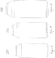
- Figures 3, 4, and 5 illustrate containers 110a, 110b, and 110c having capacities of 25 cl, 33 cl, and 50 cl capacity, respectively.
- Container 110a has a body dimension of 52 mm, an end diameter of 34 mm, and a height of 135 mm.
- Container 110b has a body diameter of 58 mm, an end diameter of 38 mm, and a height of 150 mm.
- Container 110c has a body diameter of 65 mm, an end diameter of 42 mm, and a height of 175 mm.
- Other preferred sizes are contemplated.
- a container having a 75 cl capacity may have a body diameter of 73 mm and an end diameter of 48 mm.
- a container having a 100 cl capacity may have a body diameter of 82 mm and an end diameter of 52 mm.
- the heights of the 75 cl and 100 cl containers may be chosen according to the parameters understood by persons familiar with can and metal bottle technology based upon considering the disclosure herein.
- the can bodies described herein are formed by conventional can making techniques.
- Can body 12 is formed by a conventional drawing and ironing process, followed by a conventional die necking process for forming neck 40. After the can body goes through a trimming and flanging process, it is ready for being coupled to an end in a double seaming process.
- the processes described above are well known to persons familiar with can making and seaming technology.
- the base preferably is a conventional, domed base.
- can body 12 is capable of being manufactured on high speed can making equipment, such as at speeds of over 750 cans per minute or over 1,000 cans per minute, as distinguished from the manufacture of metal bottles which is significantly slower.
- the configuration of can 10 is suitable for high speed filling and seaming at speeds of over 1000 cans per minute, as the diameter of the body is large enough to be filled without slowing down conventional filling machines.
- can body 10 although manufactured from thin material is strong enough to withstand the axial loads from the filling and seaming machines.
- a can 10 with thin wall of only 34t and necks of thickness 54t have an axial strength of at least 400 N.
Landscapes
- Engineering & Computer Science (AREA)
- Mechanical Engineering (AREA)
- Rigid Containers With Two Or More Constituent Elements (AREA)
- Containers Having Bodies Formed In One Piece (AREA)
- Stackable Containers (AREA)
- Containers Opened By Tearing Frangible Portions (AREA)
Claims (15)
- Getränkedose (10, 110a, 110b, 110c), die Folgendes einschließt:einen gezogenen und abgestreckten Metall-Getränkedosenkörper (12), der eine Basis (20, 20a, 20b), eine zylindrische Seitenwand (36), die sich von der Basis aus nach oben erstreckt, und einen sich verjüngenden Hals (40), der sich von der Seitenwand aus nach oben erstreckt, einschließt, wobei die Basis einen Standring (24) und eine Wölbung (30), die innerhalb des Standrings angeordnet ist, einschließt,ein Ende (14), das mit einem oberen Ende (46) des Halses an einem Falz (16) zusammengefalzt ist, wobei das Ende eine Mittelplatte (56), die innerhalb des Falzes angeordnet ist, eine abgedichtete Gießöffnung, die in der Mittelplatte geformt ist, einschließt, wobei die abgedichtete Gießöffnung dafür eingerichtet ist, ohne Werkzeuge durch einen Verbraucher geöffnet zu werden, und dadurch gekennzeichnet, dassder Dosenkörper einen Durchmesser an der zylindrischen Seitenwand hat, der zwischen 40 % und 100 % größer ist als ein Außendurchmesser des Falzes.
- Getränkedose (10, 110a, 110b, 110c), die Folgendes einschließt:einen gezogenen und abgestreckten Metall-Getränkedosenkörper (12), der eine Basis (20, 20a, 20b), eine zylindrische Seitenwand (36), die sich von der Basis aus nach oben erstreckt, und einen sich verjüngenden Hals (40), der sich von der Seitenwand aus nach oben erstreckt, einschließt, wobei die Basis einen Standring (24) und eine Wölbung (30), die innerhalb des Standrings angeordnet ist, einschließt,ein Ende (14), das mit einem oberen Ende (46) des Halses an einem Falz (16) zusammengefalzt ist, wobei das Ende eine Mittelplatte (56), die innerhalb des Falzes angeordnet ist, eine abgedichtete Gießöffnung, die in der Mittelplatte geformt ist, einschließt, wobei die abgedichtete Gießöffnung dafür eingerichtet ist, ohne Werkzeuge durch einen Verbraucher geöffnet zu werden, und dadurch gekennzeichnet, dassein Verhältnis zwischen einer durchschnittlichen Dosenseitenwanddicke, gemessen in Einheiten von Zehntausendstel Zoll (0,00254 mm), und einem Dosenkörperdurchmesser an der zylindrischen Seitenwand, gemessen in Einheiten von Zoll (25,4 mm), geringer als ungefähr 25 ist.
- Getränkedose nach Anspruch 1, wobei ein Verhältnis zwischen einer durchschnittlichen Dosenseitenwanddicke, gemessen in Einheiten von Zehntausendstel Zoll (0,00254 mm), und einem Dosenkörperdurchmesser an der zylindrischen Seitenwand, gemessen in Einheiten von Zoll (25,4 mm), geringer als ungefähr 25 ist.
- Getränkedose nach Anspruch 2, wobei der Dosenkörper einen Durchmesser hat, der zwischen 40 % und 100 % größer ist als ein Außendurchmesser des Falzes.
- Getränkedose nach einem der Ansprüche 1 bis 3, wobei der Dosenkörperdurchmesser entweder zwischen 40 % und 80 %, zwischen 45 % und 60 % oder zwischen 48 % und 55 % größer ist als der Außendurchmesser des Falzes.
- Getränkedose nach einem der Ansprüche 1 bis 3, wobei der Hals von der Vertikalen um einen Winkel von mehr als 15 Grad oder um einen Winkel von zwischen ungefähr 15 Grad und ungefähr 45 Grad geneigt ist und wahlweise wobei der Hals zwischen einem Übergang zwischen dem Hals und der Dosenkörperseitenwand und einem Übergang zwischen dem Hals und dem Falz im Wesentlichen gerade im Querschnitt ist oder wobei der Hals zwischen einem Übergang zwischen dem Hals und der Dosenkörperseitenwand und einem Übergang zwischen dem Hals und dem Falz gekrümmte Abschnitte im Querschnitt einschließt und keine Tangente an irgendeinem Punkt auf der Krümmung mehr als 45 Grad geneigt ist oder wobei der Hals durch mehrere Stufenhöcker geformt wird.
- Getränkedose nach einem der Ansprüche 1 bis 3, wobei der Hals von der Vertikalen um einen Winkel von zwischen ungefähr 20 Grad und ungefähr 35 Grad oder um einen Winkel von zwischen ungefähr 25 Grad und ungefähr 35 Grad geneigt ist.
- Getränkedose nach einem der Ansprüche 1 bis 3, wobei eine durchschnittliche Wanddicke des Halses dicker ist als die durchschnittliche Wanddicke der zylindrischen Seitenwand, vorzugsweise um zwischen ungefähr 0,001 Zoll (0,0254 mm) und ungefähr 0,0035 Zoll (0,0889 mm), bevorzugterweise um zwischen ungefähr 0,0015 Zoll (0,0381 mm) und ungefähr 0,0025 Zoll (0,0635 mm), insbesondere um ungefähr 0,002 Zoll (0,0508 mm).
- Getränkedose nach einem der Ansprüche 1 bis 3, wobei das Metall Aluminium ist und ein Verhältnis einer Dosenwanddicke, gemessen in Einheiten von Zehntausendstel Zoll (0,00254 mm), zu einem Dosenkörperdurchmesser, gemessen in Einheiten von Zoll (25,4 mm), eines von weniger als ungefähr 25, zwischen 12 und 40, zwischen 16 und 32, zwischen 19 und 28, zwischen 20 und 26, zwischen 22 und 24 beträgt.
- Getränkedose nach einem der Ansprüche 1 bis 3, wobei der Außendurchmesser des Falzes geringer ist als ein Innendurchmesser der Basis, so dass eine Basis einer ersten Dose auf das Ende einer zweiten Dose gestapelt werden kann, und/oder wobei ein Außendurchmesser des Falzes ungefähr der gleiche ist wie ein Innendurchmesser der Basis oder größer als derselbe, so dass ein Ende einer ersten Getränkedose in einer Presspassung auf eine Basis einer zweiten Getränkedose stapelbar ist, und wahlweise wobei die Basis eine innere Umformungsrille hat, in die das Ende passt.
- Getränkedose nach einem der Ansprüche 1 bis 3, wobei das Metall Stahl ist und ein Verhältnis einer Dosenwanddicke, gemessen in Einheiten von Zehntausendstel Zoll (0,00254 mm), zu einem Dosenkörperdurchmesser, gemessen in Einheiten von Zoll (25,4 mm), eines von weniger als ungefähr 16, zwischen 7 und 25, zwischen 10 und 20, zwischen 11,5 und 18, zwischen 12,5 und 17 beträgt.
- Getränkedose nach einem der Ansprüche 1 bis 3, wobei der Dosenkörper aus einem Aluminium der Serie 3000 geformt ist und/oder wobei der Dosenkörper einen Durchmesser von zwischen 2,0 Zoll (50,8 mm) und 3,0 Zoll (76,2 mm) hat.
- Getränkedose nach einem der Ansprüche 1 bis 3, wobei der Dosenkörper aus Aluminium besteht und einen Durchmesser von zwischen ungefähr 2,125 Zoll (53,975 mm) und ungefähr 2,75 Zoll (69,85 mm) hat und der Dosenkörper eine durchschnittliche Seitenwanddicke zwischen 0,003 Zoll (0,0762 mm) und 0,005 Zoll (0,127 mm) hat und wahlweise wobei die durchschnittliche Seitenwanddicke zwischen 0,0034 Zoll (0,08636 mm) und 0,0043 Zoll (0,10922 mm) beträgt.
- Getränkedose nach einem der Ansprüche 1 bis 3, wobei der Dosenkörper aus Stahl besteht und einen Durchmesser von zwischen ungefähr 2,125 Zoll (53,975 mm) und ungefähr 2,75 Zoll (69,85 mm) hat und der Dosenkörper eine durchschnittliche Seitenwanddicke zwischen 0,0020 Zoll (0,0508 mm) und 0,0028 Zoll (0,07112 mm) hat und wahlweise wobei die durchschnittliche Seitenwanddicke zwischen 0,0023 Zoll (0,05842 mm) und 0,0025 Zoll (0,0635 mm) beträgt.
- Getränkedose nach einem der Ansprüche 1 bis 3, wobei das Dosenende ein voll öffnendes Dosenende ist und/oder wobei die Kerbe der Mittelplatte eine Gießöffnung definiert, die dazu in der Lage ist, auf ein Anheben der Lasche hin geöffnet zu werden, während die Lasche vollständig innerhalb des Falzes angeordnet ist, und/oder wobei die abgedichtete Gießöffnung eine Kerbe ist, die in der Mittelplatte geformt ist, wobei das Ende ferner eine Lasche einschließt, die durch einen Niet an die Mittelplatte gekoppelt ist.
Applications Claiming Priority (2)
| Application Number | Priority Date | Filing Date | Title |
|---|---|---|---|
| US201361787191P | 2013-03-15 | 2013-03-15 | |
| PCT/US2014/023933 WO2014150673A1 (en) | 2013-03-15 | 2014-03-12 | Necked beverage can having a seamed-on end |
Publications (2)
| Publication Number | Publication Date |
|---|---|
| EP2969795A1 EP2969795A1 (de) | 2016-01-20 |
| EP2969795B1 true EP2969795B1 (de) | 2016-12-07 |
Family
ID=50588824
Family Applications (1)
| Application Number | Title | Priority Date | Filing Date |
|---|---|---|---|
| EP14719916.0A Not-in-force EP2969795B1 (de) | 2013-03-15 | 2014-03-12 | Eingeschnürte getränkedose mit angenähtem ende |
Country Status (13)
| Country | Link |
|---|---|
| US (1) | US10246218B2 (de) |
| EP (1) | EP2969795B1 (de) |
| JP (1) | JP2016515983A (de) |
| CN (1) | CN105492330B (de) |
| AU (1) | AU2014235746B2 (de) |
| BR (1) | BR112015023580A2 (de) |
| CA (1) | CA2906495A1 (de) |
| ES (1) | ES2618049T3 (de) |
| MX (1) | MX366126B (de) |
| PL (1) | PL2969795T3 (de) |
| SA (1) | SA515361155B1 (de) |
| WO (1) | WO2014150673A1 (de) |
| ZA (1) | ZA201506784B (de) |
Families Citing this family (28)
| Publication number | Priority date | Publication date | Assignee | Title |
|---|---|---|---|---|
| US11111050B2 (en) * | 2014-07-01 | 2021-09-07 | Mead Johnson Nutrition Company | Pillar-shaped container |
| MX2017004818A (es) | 2014-10-15 | 2017-08-02 | Ball Corp | Aparato y metodo para formar hombro y cuello de recipiente metalico. |
| EP3212347A4 (de) | 2014-10-28 | 2018-07-18 | Ball Corporation | Vorrichtung und verfahren zur herstellung eines bechers mit einem verbesserten boden |
| EP3647217B1 (de) * | 2016-02-29 | 2022-08-03 | Crown Packaging Technology, Inc. | Konkaves dosenende |
| US10246250B2 (en) | 2016-04-21 | 2019-04-02 | Crown Packaging Technology, Inc. | Beverage can having a grommet |
| ES2880352T3 (es) * | 2016-05-24 | 2021-11-24 | Ball Beverage Packaging Europe Ltd | Tapa para lata de aluminio para bebidas |
| US11447290B2 (en) | 2016-05-31 | 2022-09-20 | Ball Beverage Packaging Europe Limited | Lid for an aluminum beverage can |
| DE102016112953A1 (de) | 2016-07-14 | 2018-01-18 | Gregor Anton Piech | Metallische Dose und zugehöriger Dosendeckel |
| US10875076B2 (en) | 2017-02-07 | 2020-12-29 | Ball Corporation | Tapered metal cup and method of forming the same |
| US11370579B2 (en) | 2017-02-07 | 2022-06-28 | Ball Corporation | Tapered metal cup and method of forming the same |
| WO2019217633A1 (en) | 2018-05-11 | 2019-11-14 | Stolle Machinery Company, Llc | Rotary manifold |
| CN115958118A (zh) | 2018-05-11 | 2023-04-14 | 斯多里机械有限责任公司 | 快速更换工具组件 |
| EP3790822B1 (de) | 2018-05-11 | 2025-02-26 | Stolle Machinery Company, LLC | Prozessschaftwerkzeuganordnung |
| JP7331017B2 (ja) | 2018-05-11 | 2023-08-22 | ストール マシーナリ カンパニー,エルエルシー | 駆動アセンブリ |
| EP3790820B1 (de) | 2018-05-11 | 2025-03-05 | Stolle Machinery Company, LLC | Schnellwechseltransferanordnung |
| US10934104B2 (en) | 2018-05-11 | 2021-03-02 | Stolle Machinery Company, Llc | Infeed assembly quick change features |
| US11534817B2 (en) | 2018-05-11 | 2022-12-27 | Stolle Machinery Company, Llc | Infeed assembly full inspection assembly |
| USD950318S1 (en) | 2018-05-24 | 2022-05-03 | Ball Corporation | Tapered cup |
| USD906056S1 (en) | 2018-12-05 | 2020-12-29 | Ball Corporation | Tapered cup |
| USD968893S1 (en) | 2019-06-24 | 2022-11-08 | Ball Corporation | Tapered cup |
| US11420242B2 (en) | 2019-08-16 | 2022-08-23 | Stolle Machinery Company, Llc | Reformer assembly |
| USD953811S1 (en) | 2020-02-14 | 2022-06-07 | Ball Corporation | Tapered cup |
| USD974845S1 (en) | 2020-07-15 | 2023-01-10 | Ball Corporation | Tapered cup |
| WO2022094241A1 (en) | 2020-10-30 | 2022-05-05 | Ball Corporation | Tapered cup and method of forming the same |
| USD1012617S1 (en) | 2021-02-22 | 2024-01-30 | Ball Corporation | Tapered cup |
| USD976110S1 (en) * | 2021-05-21 | 2023-01-24 | The Clorox Company | Bottle |
| USD1035386S1 (en) | 2021-12-08 | 2024-07-16 | Ball Corporation | Tapered cup |
| EP4474303A1 (de) * | 2023-06-05 | 2024-12-11 | AHS Lasauard GmbH | Stapelbare kunststoffkonservenvorrichtung erstellt aus einem behälterhalbzeug aus kunststoff sowie verwendung |
Family Cites Families (43)
| Publication number | Priority date | Publication date | Assignee | Title |
|---|---|---|---|---|
| US3608774A (en) * | 1970-01-07 | 1971-09-28 | Nat Steel Corp | Drawn can for accommodating conventional openers |
| US3795340A (en) | 1972-08-04 | 1974-03-05 | Continental Can Co | Tab mounting arrangement for easy opening can end |
| US3858754A (en) | 1973-10-29 | 1975-01-07 | Nat Can Corp | Container end with pre-bulge |
| US3934750A (en) | 1974-11-08 | 1976-01-27 | Continental Can Company, Inc. | Non-detachable end unit |
| US3967754A (en) | 1975-05-12 | 1976-07-06 | Continental Can Company, Inc. | Pull tab anti-rotation mounting |
| US4014455A (en) | 1976-06-21 | 1977-03-29 | American Can Company | Accurate flow control container means |
| USD272508S (en) | 1980-08-07 | 1984-02-07 | Dart Industries Inc. | Canister jar or the like |
| US4318493A (en) * | 1980-09-26 | 1982-03-09 | The Continental Group, Inc. | Easy opening container |
| USD275834S (en) | 1981-04-23 | 1984-10-09 | Metal Box Limited | Can body |
| US4550851A (en) | 1984-01-16 | 1985-11-05 | Ernest R. Garrett | Container top opening means |
| US4564119A (en) * | 1984-12-07 | 1986-01-14 | Nippon Light Metal Co., Ltd. | Aluminum can end |
| US5355710A (en) * | 1992-07-31 | 1994-10-18 | Aluminum Company Of America | Method and apparatus for necking a metal container and resultant container |
| US5346087A (en) * | 1993-07-23 | 1994-09-13 | Klein Gerald B | Reinforced beverage can end with push down gate |
| US5572893A (en) | 1994-12-01 | 1996-11-12 | Goda; Mark E. | Method of necking and impact extruded metal container |
| GB9510515D0 (en) * | 1995-05-24 | 1995-07-19 | Metal Box Plc | Containers |
| US5645190A (en) * | 1995-09-29 | 1997-07-08 | Goldberg; Norton Robert | Aluminum beverage can |
| US5704240A (en) * | 1996-05-08 | 1998-01-06 | Aluminum Company Of America | Method and apparatus for forming threads in metal containers |
| US6499622B1 (en) | 1999-12-08 | 2002-12-31 | Metal Container Corporation, Inc. | Can lid closure and method of joining a can lid closure to a can body |
| USD448666S1 (en) | 2001-01-12 | 2001-10-02 | Crown Cork & Seal Technologies Corporation | Can end |
| KR200233702Y1 (ko) | 2001-03-27 | 2001-10-18 | 황보연 | 캔 개봉장치 |
| US7819275B2 (en) | 2001-07-03 | 2010-10-26 | Container Development, Ltd. | Can shell and double-seamed can end |
| US7591392B2 (en) | 2002-04-22 | 2009-09-22 | Crown Packaging Technology, Inc. | Can end |
| US6889862B2 (en) | 2002-09-19 | 2005-05-10 | Ball Corporation | Large opening beverage container |
| CN2583002Y (zh) * | 2002-09-23 | 2003-10-29 | 淄博富源工贸有限公司 | 塑膜金属组合端盖包装罐 |
| ATE363250T1 (de) * | 2003-11-07 | 2007-06-15 | Impliant Ltd | Wirbelsäulenprothesen |
| US7398894B2 (en) * | 2003-11-24 | 2008-07-15 | Metal Container Corporation | Container bottom, method of manufacture, and method of testing |
| CN100509570C (zh) * | 2004-01-07 | 2009-07-08 | 三得利株式会社 | 罐体及罐 |
| US8109406B2 (en) | 2006-10-26 | 2012-02-07 | Charles Chang | Beverage container construction |
| USD603722S1 (en) | 2007-05-31 | 2009-11-10 | Rexam Beverage Can Company | Beverage can |
| USD587137S1 (en) | 2008-04-22 | 2009-02-24 | Rexam Beverage Can Company | Container body |
| USD639164S1 (en) | 2008-04-30 | 2011-06-07 | Rexam Beverage Can Company | Container body |
| USD622145S1 (en) | 2008-04-30 | 2010-08-24 | Rexam Beverage Can Company | Container body |
| USD638708S1 (en) | 2008-04-30 | 2011-05-31 | Rexam Beverage Can Company | Container body |
| US8939308B2 (en) * | 2009-09-04 | 2015-01-27 | Crown Packaging Technology, Inc. | Full aperture beverage end |
| USD632588S1 (en) | 2010-01-11 | 2011-02-15 | Rexam Beverage Can Company | Container |
| US20110303672A1 (en) * | 2010-06-09 | 2011-12-15 | Brian Fields | Flap score venting of can end |
| USD653538S1 (en) | 2010-07-14 | 2012-02-07 | Millercoors, Llc | Beverage container neck with end |
| USD684051S1 (en) | 2011-06-09 | 2013-06-11 | Crown Packaging Technology, Inc. | Can top |
| USD707569S1 (en) | 2011-07-15 | 2014-06-24 | Rexam Beverage Can Company | Container body |
| USD707568S1 (en) | 2011-07-15 | 2014-06-24 | Rexam Beverage Can Company | Container body |
| SG195407A1 (en) * | 2012-05-17 | 2013-12-30 | Crown Packaging Technology Inc | Beverage can and can end for same |
| CA2886643A1 (en) * | 2012-10-01 | 2014-04-10 | Crown Packaging Technology, Inc. | Beverage can ends suitable for small diameters |
| USD701464S1 (en) | 2013-03-20 | 2014-03-25 | Daiwa Can Company | Can |
-
2014
- 2014-03-12 WO PCT/US2014/023933 patent/WO2014150673A1/en not_active Ceased
- 2014-03-12 JP JP2016501387A patent/JP2016515983A/ja active Pending
- 2014-03-12 EP EP14719916.0A patent/EP2969795B1/de not_active Not-in-force
- 2014-03-12 PL PL14719916T patent/PL2969795T3/pl unknown
- 2014-03-12 ES ES14719916.0T patent/ES2618049T3/es active Active
- 2014-03-12 CA CA2906495A patent/CA2906495A1/en not_active Abandoned
- 2014-03-12 AU AU2014235746A patent/AU2014235746B2/en not_active Ceased
- 2014-03-12 US US14/773,892 patent/US10246218B2/en active Active
- 2014-03-12 CN CN201480028130.4A patent/CN105492330B/zh not_active Expired - Fee Related
- 2014-03-12 BR BR112015023580A patent/BR112015023580A2/pt not_active Application Discontinuation
- 2014-03-12 MX MX2015012852A patent/MX366126B/es active IP Right Grant
-
2015
- 2015-09-14 ZA ZA2015/06784A patent/ZA201506784B/en unknown
- 2015-09-15 SA SA515361155A patent/SA515361155B1/ar unknown
Non-Patent Citations (1)
| Title |
|---|
| None * |
Also Published As
| Publication number | Publication date |
|---|---|
| US10246218B2 (en) | 2019-04-02 |
| CN105492330B (zh) | 2017-12-15 |
| ZA201506784B (en) | 2017-07-26 |
| MX366126B (es) | 2019-06-27 |
| MX2015012852A (es) | 2016-05-09 |
| CA2906495A1 (en) | 2014-09-25 |
| WO2014150673A1 (en) | 2014-09-25 |
| BR112015023580A2 (pt) | 2017-07-18 |
| AU2014235746B2 (en) | 2017-12-14 |
| PL2969795T3 (pl) | 2017-06-30 |
| SA515361155B1 (ar) | 2019-07-29 |
| CN105492330A (zh) | 2016-04-13 |
| EP2969795A1 (de) | 2016-01-20 |
| AU2014235746A1 (en) | 2015-10-01 |
| US20160031594A1 (en) | 2016-02-04 |
| ES2618049T3 (es) | 2017-06-20 |
| WO2014150673A8 (en) | 2015-10-22 |
| JP2016515983A (ja) | 2016-06-02 |
Similar Documents
| Publication | Publication Date | Title |
|---|---|---|
| EP2969795B1 (de) | Eingeschnürte getränkedose mit angenähtem ende | |
| US5718352A (en) | Threaded aluminum cans and methods of manufacture | |
| US5704240A (en) | Method and apparatus for forming threads in metal containers | |
| US6010026A (en) | Assembly of aluminum can and threaded sleeve | |
| JP5597333B2 (ja) | 金属ボトル缶およびその製造方法 | |
| US6010028A (en) | Lightweight reclosable can with attached threaded pour spout and methods of manufacture | |
| US10850888B2 (en) | Concave can end | |
| US20150343516A1 (en) | Two iron tool pack for forming tall metal bottle shaped containers | |
| CA2872448C (en) | Metallic end closure with tear panel having improved rigidity | |
| US5421480A (en) | Thin-walled can having a displaceable bottom | |
| JP2012192984A5 (de) | ||
| US9327859B1 (en) | Metal bottle type container and related methodology | |
| WO2017008961A1 (en) | Aluminium beverage can | |
| EP3464092B1 (de) | Deckel für eine getränkedose aus aluminium |
Legal Events
| Date | Code | Title | Description |
|---|---|---|---|
| PUAI | Public reference made under article 153(3) epc to a published international application that has entered the european phase |
Free format text: ORIGINAL CODE: 0009012 |
|
| 17P | Request for examination filed |
Effective date: 20150929 |
|
| AK | Designated contracting states |
Kind code of ref document: A1 Designated state(s): AL AT BE BG CH CY CZ DE DK EE ES FI FR GB GR HR HU IE IS IT LI LT LU LV MC MK MT NL NO PL PT RO RS SE SI SK SM TR |
|
| AX | Request for extension of the european patent |
Extension state: BA ME |
|
| DAX | Request for extension of the european patent (deleted) | ||
| GRAP | Despatch of communication of intention to grant a patent |
Free format text: ORIGINAL CODE: EPIDOSNIGR1 |
|
| INTG | Intention to grant announced |
Effective date: 20160812 |
|
| GRAJ | Information related to disapproval of communication of intention to grant by the applicant or resumption of examination proceedings by the epo deleted |
Free format text: ORIGINAL CODE: EPIDOSDIGR1 |
|
| GRAR | Information related to intention to grant a patent recorded |
Free format text: ORIGINAL CODE: EPIDOSNIGR71 |
|
| GRAS | Grant fee paid |
Free format text: ORIGINAL CODE: EPIDOSNIGR3 |
|
| GRAA | (expected) grant |
Free format text: ORIGINAL CODE: 0009210 |
|
| STAA | Information on the status of an ep patent application or granted ep patent |
Free format text: STATUS: THE PATENT HAS BEEN GRANTED |
|
| INTC | Intention to grant announced (deleted) | ||
| INTG | Intention to grant announced |
Effective date: 20161027 |
|
| AK | Designated contracting states |
Kind code of ref document: B1 Designated state(s): AL AT BE BG CH CY CZ DE DK EE ES FI FR GB GR HR HU IE IS IT LI LT LU LV MC MK MT NL NO PL PT RO RS SE SI SK SM TR |
|
| REG | Reference to a national code |
Ref country code: GB Ref legal event code: FG4D |
|
| REG | Reference to a national code |
Ref country code: CH Ref legal event code: EP Ref country code: AT Ref legal event code: REF Ref document number: 851463 Country of ref document: AT Kind code of ref document: T Effective date: 20161215 |
|
| REG | Reference to a national code |
Ref country code: IE Ref legal event code: FG4D |
|
| REG | Reference to a national code |
Ref country code: DE Ref legal event code: R096 Ref document number: 602014005377 Country of ref document: DE |
|
| PG25 | Lapsed in a contracting state [announced via postgrant information from national office to epo] |
Ref country code: LV Free format text: LAPSE BECAUSE OF FAILURE TO SUBMIT A TRANSLATION OF THE DESCRIPTION OR TO PAY THE FEE WITHIN THE PRESCRIBED TIME-LIMIT Effective date: 20161207 |
|
| REG | Reference to a national code |
Ref country code: NL Ref legal event code: FP |
|
| REG | Reference to a national code |
Ref country code: FR Ref legal event code: PLFP Year of fee payment: 4 |
|
| REG | Reference to a national code |
Ref country code: LT Ref legal event code: MG4D |
|
| PG25 | Lapsed in a contracting state [announced via postgrant information from national office to epo] |
Ref country code: NO Free format text: LAPSE BECAUSE OF FAILURE TO SUBMIT A TRANSLATION OF THE DESCRIPTION OR TO PAY THE FEE WITHIN THE PRESCRIBED TIME-LIMIT Effective date: 20170307 Ref country code: GR Free format text: LAPSE BECAUSE OF FAILURE TO SUBMIT A TRANSLATION OF THE DESCRIPTION OR TO PAY THE FEE WITHIN THE PRESCRIBED TIME-LIMIT Effective date: 20170308 Ref country code: LT Free format text: LAPSE BECAUSE OF FAILURE TO SUBMIT A TRANSLATION OF THE DESCRIPTION OR TO PAY THE FEE WITHIN THE PRESCRIBED TIME-LIMIT Effective date: 20161207 Ref country code: SE Free format text: LAPSE BECAUSE OF FAILURE TO SUBMIT A TRANSLATION OF THE DESCRIPTION OR TO PAY THE FEE WITHIN THE PRESCRIBED TIME-LIMIT Effective date: 20161207 |
|
| PG25 | Lapsed in a contracting state [announced via postgrant information from national office to epo] |
Ref country code: RS Free format text: LAPSE BECAUSE OF FAILURE TO SUBMIT A TRANSLATION OF THE DESCRIPTION OR TO PAY THE FEE WITHIN THE PRESCRIBED TIME-LIMIT Effective date: 20161207 Ref country code: FI Free format text: LAPSE BECAUSE OF FAILURE TO SUBMIT A TRANSLATION OF THE DESCRIPTION OR TO PAY THE FEE WITHIN THE PRESCRIBED TIME-LIMIT Effective date: 20161207 Ref country code: HR Free format text: LAPSE BECAUSE OF FAILURE TO SUBMIT A TRANSLATION OF THE DESCRIPTION OR TO PAY THE FEE WITHIN THE PRESCRIBED TIME-LIMIT Effective date: 20161207 |
|
| REG | Reference to a national code |
Ref country code: ES Ref legal event code: FG2A Ref document number: 2618049 Country of ref document: ES Kind code of ref document: T3 Effective date: 20170620 |
|
| PG25 | Lapsed in a contracting state [announced via postgrant information from national office to epo] |
Ref country code: CZ Free format text: LAPSE BECAUSE OF FAILURE TO SUBMIT A TRANSLATION OF THE DESCRIPTION OR TO PAY THE FEE WITHIN THE PRESCRIBED TIME-LIMIT Effective date: 20161207 Ref country code: SK Free format text: LAPSE BECAUSE OF FAILURE TO SUBMIT A TRANSLATION OF THE DESCRIPTION OR TO PAY THE FEE WITHIN THE PRESCRIBED TIME-LIMIT Effective date: 20161207 Ref country code: EE Free format text: LAPSE BECAUSE OF FAILURE TO SUBMIT A TRANSLATION OF THE DESCRIPTION OR TO PAY THE FEE WITHIN THE PRESCRIBED TIME-LIMIT Effective date: 20161207 Ref country code: IS Free format text: LAPSE BECAUSE OF FAILURE TO SUBMIT A TRANSLATION OF THE DESCRIPTION OR TO PAY THE FEE WITHIN THE PRESCRIBED TIME-LIMIT Effective date: 20170407 Ref country code: RO Free format text: LAPSE BECAUSE OF FAILURE TO SUBMIT A TRANSLATION OF THE DESCRIPTION OR TO PAY THE FEE WITHIN THE PRESCRIBED TIME-LIMIT Effective date: 20161207 |
|
| PG25 | Lapsed in a contracting state [announced via postgrant information from national office to epo] |
Ref country code: BE Free format text: LAPSE BECAUSE OF FAILURE TO SUBMIT A TRANSLATION OF THE DESCRIPTION OR TO PAY THE FEE WITHIN THE PRESCRIBED TIME-LIMIT Effective date: 20161207 Ref country code: SM Free format text: LAPSE BECAUSE OF FAILURE TO SUBMIT A TRANSLATION OF THE DESCRIPTION OR TO PAY THE FEE WITHIN THE PRESCRIBED TIME-LIMIT Effective date: 20161207 Ref country code: BG Free format text: LAPSE BECAUSE OF FAILURE TO SUBMIT A TRANSLATION OF THE DESCRIPTION OR TO PAY THE FEE WITHIN THE PRESCRIBED TIME-LIMIT Effective date: 20170307 Ref country code: PT Free format text: LAPSE BECAUSE OF FAILURE TO SUBMIT A TRANSLATION OF THE DESCRIPTION OR TO PAY THE FEE WITHIN THE PRESCRIBED TIME-LIMIT Effective date: 20170407 |
|
| REG | Reference to a national code |
Ref country code: DE Ref legal event code: R097 Ref document number: 602014005377 Country of ref document: DE |
|
| PLBE | No opposition filed within time limit |
Free format text: ORIGINAL CODE: 0009261 |
|
| STAA | Information on the status of an ep patent application or granted ep patent |
Free format text: STATUS: NO OPPOSITION FILED WITHIN TIME LIMIT |
|
| REG | Reference to a national code |
Ref country code: CH Ref legal event code: PL |
|
| 26N | No opposition filed |
Effective date: 20170908 |
|
| PG25 | Lapsed in a contracting state [announced via postgrant information from national office to epo] |
Ref country code: MC Free format text: LAPSE BECAUSE OF FAILURE TO SUBMIT A TRANSLATION OF THE DESCRIPTION OR TO PAY THE FEE WITHIN THE PRESCRIBED TIME-LIMIT Effective date: 20161207 Ref country code: DK Free format text: LAPSE BECAUSE OF FAILURE TO SUBMIT A TRANSLATION OF THE DESCRIPTION OR TO PAY THE FEE WITHIN THE PRESCRIBED TIME-LIMIT Effective date: 20161207 Ref country code: SI Free format text: LAPSE BECAUSE OF FAILURE TO SUBMIT A TRANSLATION OF THE DESCRIPTION OR TO PAY THE FEE WITHIN THE PRESCRIBED TIME-LIMIT Effective date: 20161207 |
|
| REG | Reference to a national code |
Ref country code: IE Ref legal event code: MM4A |
|
| PG25 | Lapsed in a contracting state [announced via postgrant information from national office to epo] |
Ref country code: LU Free format text: LAPSE BECAUSE OF NON-PAYMENT OF DUE FEES Effective date: 20170312 |
|
| PG25 | Lapsed in a contracting state [announced via postgrant information from national office to epo] |
Ref country code: CH Free format text: LAPSE BECAUSE OF NON-PAYMENT OF DUE FEES Effective date: 20170331 Ref country code: IE Free format text: LAPSE BECAUSE OF NON-PAYMENT OF DUE FEES Effective date: 20170312 Ref country code: LI Free format text: LAPSE BECAUSE OF NON-PAYMENT OF DUE FEES Effective date: 20170331 |
|
| REG | Reference to a national code |
Ref country code: FR Ref legal event code: PLFP Year of fee payment: 5 |
|
| PGFP | Annual fee paid to national office [announced via postgrant information from national office to epo] |
Ref country code: NL Payment date: 20180321 Year of fee payment: 5 |
|
| PGFP | Annual fee paid to national office [announced via postgrant information from national office to epo] |
Ref country code: PL Payment date: 20180309 Year of fee payment: 5 Ref country code: TR Payment date: 20180312 Year of fee payment: 5 |
|
| PGFP | Annual fee paid to national office [announced via postgrant information from national office to epo] |
Ref country code: ES Payment date: 20180424 Year of fee payment: 5 |
|
| PGFP | Annual fee paid to national office [announced via postgrant information from national office to epo] |
Ref country code: IT Payment date: 20180326 Year of fee payment: 5 |
|
| PG25 | Lapsed in a contracting state [announced via postgrant information from national office to epo] |
Ref country code: MT Free format text: LAPSE BECAUSE OF NON-PAYMENT OF DUE FEES Effective date: 20170312 |
|
| PG25 | Lapsed in a contracting state [announced via postgrant information from national office to epo] |
Ref country code: HU Free format text: LAPSE BECAUSE OF FAILURE TO SUBMIT A TRANSLATION OF THE DESCRIPTION OR TO PAY THE FEE WITHIN THE PRESCRIBED TIME-LIMIT; INVALID AB INITIO Effective date: 20140312 |
|
| PG25 | Lapsed in a contracting state [announced via postgrant information from national office to epo] |
Ref country code: CY Free format text: LAPSE BECAUSE OF FAILURE TO SUBMIT A TRANSLATION OF THE DESCRIPTION OR TO PAY THE FEE WITHIN THE PRESCRIBED TIME-LIMIT Effective date: 20161207 |
|
| REG | Reference to a national code |
Ref country code: NL Ref legal event code: MM Effective date: 20190401 |
|
| PG25 | Lapsed in a contracting state [announced via postgrant information from national office to epo] |
Ref country code: MK Free format text: LAPSE BECAUSE OF FAILURE TO SUBMIT A TRANSLATION OF THE DESCRIPTION OR TO PAY THE FEE WITHIN THE PRESCRIBED TIME-LIMIT Effective date: 20161207 |
|
| PG25 | Lapsed in a contracting state [announced via postgrant information from national office to epo] |
Ref country code: NL Free format text: LAPSE BECAUSE OF NON-PAYMENT OF DUE FEES Effective date: 20190401 |
|
| PG25 | Lapsed in a contracting state [announced via postgrant information from national office to epo] |
Ref country code: IT Free format text: LAPSE BECAUSE OF NON-PAYMENT OF DUE FEES Effective date: 20190312 |
|
| PGFP | Annual fee paid to national office [announced via postgrant information from national office to epo] |
Ref country code: GB Payment date: 20200323 Year of fee payment: 7 Ref country code: DE Payment date: 20200320 Year of fee payment: 7 |
|
| PGFP | Annual fee paid to national office [announced via postgrant information from national office to epo] |
Ref country code: FR Payment date: 20200320 Year of fee payment: 7 |
|
| REG | Reference to a national code |
Ref country code: ES Ref legal event code: FD2A Effective date: 20200724 |
|
| PG25 | Lapsed in a contracting state [announced via postgrant information from national office to epo] |
Ref country code: AL Free format text: LAPSE BECAUSE OF FAILURE TO SUBMIT A TRANSLATION OF THE DESCRIPTION OR TO PAY THE FEE WITHIN THE PRESCRIBED TIME-LIMIT Effective date: 20161207 |
|
| REG | Reference to a national code |
Ref country code: AT Ref legal event code: MM01 Ref document number: 851463 Country of ref document: AT Kind code of ref document: T Effective date: 20190312 |
|
| PG25 | Lapsed in a contracting state [announced via postgrant information from national office to epo] |
Ref country code: ES Free format text: LAPSE BECAUSE OF NON-PAYMENT OF DUE FEES Effective date: 20190313 |
|
| PG25 | Lapsed in a contracting state [announced via postgrant information from national office to epo] |
Ref country code: AT Free format text: LAPSE BECAUSE OF NON-PAYMENT OF DUE FEES Effective date: 20190312 |
|
| PG25 | Lapsed in a contracting state [announced via postgrant information from national office to epo] |
Ref country code: PL Free format text: LAPSE BECAUSE OF NON-PAYMENT OF DUE FEES Effective date: 20190312 |
|
| REG | Reference to a national code |
Ref country code: DE Ref legal event code: R119 Ref document number: 602014005377 Country of ref document: DE |
|
| GBPC | Gb: european patent ceased through non-payment of renewal fee |
Effective date: 20210312 |
|
| PG25 | Lapsed in a contracting state [announced via postgrant information from national office to epo] |
Ref country code: DE Free format text: LAPSE BECAUSE OF NON-PAYMENT OF DUE FEES Effective date: 20211001 Ref country code: GB Free format text: LAPSE BECAUSE OF NON-PAYMENT OF DUE FEES Effective date: 20210312 Ref country code: FR Free format text: LAPSE BECAUSE OF NON-PAYMENT OF DUE FEES Effective date: 20210331 |
|
| PG25 | Lapsed in a contracting state [announced via postgrant information from national office to epo] |
Ref country code: TR Free format text: LAPSE BECAUSE OF NON-PAYMENT OF DUE FEES Effective date: 20190312 |
|
| P01 | Opt-out of the competence of the unified patent court (upc) registered |
Effective date: 20230517 |