EP2969689B1 - System und verfahren zum optimieren des stromverbrauchs in einem hybriden elektrofahrzeug - Google Patents
System und verfahren zum optimieren des stromverbrauchs in einem hybriden elektrofahrzeug Download PDFInfo
- Publication number
- EP2969689B1 EP2969689B1 EP14775950.0A EP14775950A EP2969689B1 EP 2969689 B1 EP2969689 B1 EP 2969689B1 EP 14775950 A EP14775950 A EP 14775950A EP 2969689 B1 EP2969689 B1 EP 2969689B1
- Authority
- EP
- European Patent Office
- Prior art keywords
- electric motor
- energy
- controller
- calculating
- engine
- Prior art date
- Legal status (The legal status is an assumption and is not a legal conclusion. Google has not performed a legal analysis and makes no representation as to the accuracy of the status listed.)
- Active
Links
Images



Classifications
-
- B—PERFORMING OPERATIONS; TRANSPORTING
- B60—VEHICLES IN GENERAL
- B60K—ARRANGEMENT OR MOUNTING OF PROPULSION UNITS OR OF TRANSMISSIONS IN VEHICLES; ARRANGEMENT OR MOUNTING OF PLURAL DIVERSE PRIME-MOVERS IN VEHICLES; AUXILIARY DRIVES FOR VEHICLES; INSTRUMENTATION OR DASHBOARDS FOR VEHICLES; ARRANGEMENTS IN CONNECTION WITH COOLING, AIR INTAKE, GAS EXHAUST OR FUEL SUPPLY OF PROPULSION UNITS IN VEHICLES
- B60K6/00—Arrangement or mounting of plural diverse prime-movers for mutual or common propulsion, e.g. hybrid propulsion systems comprising electric motors and internal combustion engines
- B60K6/20—Arrangement or mounting of plural diverse prime-movers for mutual or common propulsion, e.g. hybrid propulsion systems comprising electric motors and internal combustion engines the prime-movers consisting of electric motors and internal combustion engines, e.g. HEVs
- B60K6/42—Arrangement or mounting of plural diverse prime-movers for mutual or common propulsion, e.g. hybrid propulsion systems comprising electric motors and internal combustion engines the prime-movers consisting of electric motors and internal combustion engines, e.g. HEVs characterised by the architecture of the hybrid electric vehicle
- B60K6/48—Parallel type
-
- B—PERFORMING OPERATIONS; TRANSPORTING
- B60—VEHICLES IN GENERAL
- B60W—CONJOINT CONTROL OF VEHICLE SUB-UNITS OF DIFFERENT TYPE OR DIFFERENT FUNCTION; CONTROL SYSTEMS SPECIALLY ADAPTED FOR HYBRID VEHICLES; ROAD VEHICLE DRIVE CONTROL SYSTEMS FOR PURPOSES NOT RELATED TO THE CONTROL OF A PARTICULAR SUB-UNIT
- B60W10/00—Conjoint control of vehicle sub-units of different type or different function
- B60W10/04—Conjoint control of vehicle sub-units of different type or different function including control of propulsion units
- B60W10/06—Conjoint control of vehicle sub-units of different type or different function including control of propulsion units including control of combustion engines
-
- B—PERFORMING OPERATIONS; TRANSPORTING
- B60—VEHICLES IN GENERAL
- B60W—CONJOINT CONTROL OF VEHICLE SUB-UNITS OF DIFFERENT TYPE OR DIFFERENT FUNCTION; CONTROL SYSTEMS SPECIALLY ADAPTED FOR HYBRID VEHICLES; ROAD VEHICLE DRIVE CONTROL SYSTEMS FOR PURPOSES NOT RELATED TO THE CONTROL OF A PARTICULAR SUB-UNIT
- B60W10/00—Conjoint control of vehicle sub-units of different type or different function
- B60W10/04—Conjoint control of vehicle sub-units of different type or different function including control of propulsion units
- B60W10/08—Conjoint control of vehicle sub-units of different type or different function including control of propulsion units including control of electric propulsion units, e.g. motors or generators
-
- B—PERFORMING OPERATIONS; TRANSPORTING
- B60—VEHICLES IN GENERAL
- B60W—CONJOINT CONTROL OF VEHICLE SUB-UNITS OF DIFFERENT TYPE OR DIFFERENT FUNCTION; CONTROL SYSTEMS SPECIALLY ADAPTED FOR HYBRID VEHICLES; ROAD VEHICLE DRIVE CONTROL SYSTEMS FOR PURPOSES NOT RELATED TO THE CONTROL OF A PARTICULAR SUB-UNIT
- B60W10/00—Conjoint control of vehicle sub-units of different type or different function
- B60W10/24—Conjoint control of vehicle sub-units of different type or different function including control of energy storage means
- B60W10/26—Conjoint control of vehicle sub-units of different type or different function including control of energy storage means for electrical energy, e.g. batteries or capacitors
-
- B—PERFORMING OPERATIONS; TRANSPORTING
- B60—VEHICLES IN GENERAL
- B60W—CONJOINT CONTROL OF VEHICLE SUB-UNITS OF DIFFERENT TYPE OR DIFFERENT FUNCTION; CONTROL SYSTEMS SPECIALLY ADAPTED FOR HYBRID VEHICLES; ROAD VEHICLE DRIVE CONTROL SYSTEMS FOR PURPOSES NOT RELATED TO THE CONTROL OF A PARTICULAR SUB-UNIT
- B60W20/00—Control systems specially adapted for hybrid vehicles
- B60W20/10—Controlling the power contribution of each of the prime movers to meet required power demand
- B60W20/11—Controlling the power contribution of each of the prime movers to meet required power demand using model predictive control [MPC] strategies, i.e. control methods based on models predicting performance
-
- B—PERFORMING OPERATIONS; TRANSPORTING
- B60—VEHICLES IN GENERAL
- B60W—CONJOINT CONTROL OF VEHICLE SUB-UNITS OF DIFFERENT TYPE OR DIFFERENT FUNCTION; CONTROL SYSTEMS SPECIALLY ADAPTED FOR HYBRID VEHICLES; ROAD VEHICLE DRIVE CONTROL SYSTEMS FOR PURPOSES NOT RELATED TO THE CONTROL OF A PARTICULAR SUB-UNIT
- B60W20/00—Control systems specially adapted for hybrid vehicles
- B60W20/10—Controlling the power contribution of each of the prime movers to meet required power demand
- B60W20/15—Control strategies specially adapted for achieving a particular effect
-
- B—PERFORMING OPERATIONS; TRANSPORTING
- B60—VEHICLES IN GENERAL
- B60W—CONJOINT CONTROL OF VEHICLE SUB-UNITS OF DIFFERENT TYPE OR DIFFERENT FUNCTION; CONTROL SYSTEMS SPECIALLY ADAPTED FOR HYBRID VEHICLES; ROAD VEHICLE DRIVE CONTROL SYSTEMS FOR PURPOSES NOT RELATED TO THE CONTROL OF A PARTICULAR SUB-UNIT
- B60W30/00—Purposes of road vehicle drive control systems not related to the control of a particular sub-unit, e.g. of systems using conjoint control of vehicle sub-units
- B60W30/18—Propelling the vehicle
- B60W30/18009—Propelling the vehicle related to particular drive situations
- B60W30/18109—Braking
- B60W30/18127—Regenerative braking
-
- B—PERFORMING OPERATIONS; TRANSPORTING
- B60—VEHICLES IN GENERAL
- B60K—ARRANGEMENT OR MOUNTING OF PROPULSION UNITS OR OF TRANSMISSIONS IN VEHICLES; ARRANGEMENT OR MOUNTING OF PLURAL DIVERSE PRIME-MOVERS IN VEHICLES; AUXILIARY DRIVES FOR VEHICLES; INSTRUMENTATION OR DASHBOARDS FOR VEHICLES; ARRANGEMENTS IN CONNECTION WITH COOLING, AIR INTAKE, GAS EXHAUST OR FUEL SUPPLY OF PROPULSION UNITS IN VEHICLES
- B60K6/00—Arrangement or mounting of plural diverse prime-movers for mutual or common propulsion, e.g. hybrid propulsion systems comprising electric motors and internal combustion engines
- B60K6/20—Arrangement or mounting of plural diverse prime-movers for mutual or common propulsion, e.g. hybrid propulsion systems comprising electric motors and internal combustion engines the prime-movers consisting of electric motors and internal combustion engines, e.g. HEVs
- B60K6/42—Arrangement or mounting of plural diverse prime-movers for mutual or common propulsion, e.g. hybrid propulsion systems comprising electric motors and internal combustion engines the prime-movers consisting of electric motors and internal combustion engines, e.g. HEVs characterised by the architecture of the hybrid electric vehicle
- B60K6/48—Parallel type
- B60K2006/4825—Electric machine connected or connectable to gearbox input shaft
-
- B—PERFORMING OPERATIONS; TRANSPORTING
- B60—VEHICLES IN GENERAL
- B60W—CONJOINT CONTROL OF VEHICLE SUB-UNITS OF DIFFERENT TYPE OR DIFFERENT FUNCTION; CONTROL SYSTEMS SPECIALLY ADAPTED FOR HYBRID VEHICLES; ROAD VEHICLE DRIVE CONTROL SYSTEMS FOR PURPOSES NOT RELATED TO THE CONTROL OF A PARTICULAR SUB-UNIT
- B60W50/00—Details of control systems for road vehicle drive control not related to the control of a particular sub-unit, e.g. process diagnostic or vehicle driver interfaces
- B60W2050/0062—Adapting control system settings
- B60W2050/0075—Automatic parameter input, automatic initialising or calibrating means
-
- B—PERFORMING OPERATIONS; TRANSPORTING
- B60—VEHICLES IN GENERAL
- B60W—CONJOINT CONTROL OF VEHICLE SUB-UNITS OF DIFFERENT TYPE OR DIFFERENT FUNCTION; CONTROL SYSTEMS SPECIALLY ADAPTED FOR HYBRID VEHICLES; ROAD VEHICLE DRIVE CONTROL SYSTEMS FOR PURPOSES NOT RELATED TO THE CONTROL OF A PARTICULAR SUB-UNIT
- B60W2556/00—Input parameters relating to data
- B60W2556/10—Historical data
-
- B—PERFORMING OPERATIONS; TRANSPORTING
- B60—VEHICLES IN GENERAL
- B60W—CONJOINT CONTROL OF VEHICLE SUB-UNITS OF DIFFERENT TYPE OR DIFFERENT FUNCTION; CONTROL SYSTEMS SPECIALLY ADAPTED FOR HYBRID VEHICLES; ROAD VEHICLE DRIVE CONTROL SYSTEMS FOR PURPOSES NOT RELATED TO THE CONTROL OF A PARTICULAR SUB-UNIT
- B60W2710/00—Output or target parameters relating to a particular sub-units
- B60W2710/06—Combustion engines, Gas turbines
- B60W2710/0666—Engine torque
-
- B—PERFORMING OPERATIONS; TRANSPORTING
- B60—VEHICLES IN GENERAL
- B60W—CONJOINT CONTROL OF VEHICLE SUB-UNITS OF DIFFERENT TYPE OR DIFFERENT FUNCTION; CONTROL SYSTEMS SPECIALLY ADAPTED FOR HYBRID VEHICLES; ROAD VEHICLE DRIVE CONTROL SYSTEMS FOR PURPOSES NOT RELATED TO THE CONTROL OF A PARTICULAR SUB-UNIT
- B60W2710/00—Output or target parameters relating to a particular sub-units
- B60W2710/08—Electric propulsion units
- B60W2710/083—Torque
-
- B—PERFORMING OPERATIONS; TRANSPORTING
- B60—VEHICLES IN GENERAL
- B60W—CONJOINT CONTROL OF VEHICLE SUB-UNITS OF DIFFERENT TYPE OR DIFFERENT FUNCTION; CONTROL SYSTEMS SPECIALLY ADAPTED FOR HYBRID VEHICLES; ROAD VEHICLE DRIVE CONTROL SYSTEMS FOR PURPOSES NOT RELATED TO THE CONTROL OF A PARTICULAR SUB-UNIT
- B60W2710/00—Output or target parameters relating to a particular sub-units
- B60W2710/24—Energy storage means
- B60W2710/242—Energy storage means for electrical energy
- B60W2710/244—Charge state
-
- B—PERFORMING OPERATIONS; TRANSPORTING
- B60—VEHICLES IN GENERAL
- B60W—CONJOINT CONTROL OF VEHICLE SUB-UNITS OF DIFFERENT TYPE OR DIFFERENT FUNCTION; CONTROL SYSTEMS SPECIALLY ADAPTED FOR HYBRID VEHICLES; ROAD VEHICLE DRIVE CONTROL SYSTEMS FOR PURPOSES NOT RELATED TO THE CONTROL OF A PARTICULAR SUB-UNIT
- B60W50/00—Details of control systems for road vehicle drive control not related to the control of a particular sub-unit, e.g. process diagnostic or vehicle driver interfaces
- B60W50/0097—Predicting future conditions
-
- Y—GENERAL TAGGING OF NEW TECHNOLOGICAL DEVELOPMENTS; GENERAL TAGGING OF CROSS-SECTIONAL TECHNOLOGIES SPANNING OVER SEVERAL SECTIONS OF THE IPC; TECHNICAL SUBJECTS COVERED BY FORMER USPC CROSS-REFERENCE ART COLLECTIONS [XRACs] AND DIGESTS
- Y02—TECHNOLOGIES OR APPLICATIONS FOR MITIGATION OR ADAPTATION AGAINST CLIMATE CHANGE
- Y02T—CLIMATE CHANGE MITIGATION TECHNOLOGIES RELATED TO TRANSPORTATION
- Y02T10/00—Road transport of goods or passengers
- Y02T10/10—Internal combustion engine [ICE] based vehicles
- Y02T10/40—Engine management systems
-
- Y—GENERAL TAGGING OF NEW TECHNOLOGICAL DEVELOPMENTS; GENERAL TAGGING OF CROSS-SECTIONAL TECHNOLOGIES SPANNING OVER SEVERAL SECTIONS OF THE IPC; TECHNICAL SUBJECTS COVERED BY FORMER USPC CROSS-REFERENCE ART COLLECTIONS [XRACs] AND DIGESTS
- Y02—TECHNOLOGIES OR APPLICATIONS FOR MITIGATION OR ADAPTATION AGAINST CLIMATE CHANGE
- Y02T—CLIMATE CHANGE MITIGATION TECHNOLOGIES RELATED TO TRANSPORTATION
- Y02T10/00—Road transport of goods or passengers
- Y02T10/60—Other road transportation technologies with climate change mitigation effect
- Y02T10/62—Hybrid vehicles
-
- Y—GENERAL TAGGING OF NEW TECHNOLOGICAL DEVELOPMENTS; GENERAL TAGGING OF CROSS-SECTIONAL TECHNOLOGIES SPANNING OVER SEVERAL SECTIONS OF THE IPC; TECHNICAL SUBJECTS COVERED BY FORMER USPC CROSS-REFERENCE ART COLLECTIONS [XRACs] AND DIGESTS
- Y02—TECHNOLOGIES OR APPLICATIONS FOR MITIGATION OR ADAPTATION AGAINST CLIMATE CHANGE
- Y02T—CLIMATE CHANGE MITIGATION TECHNOLOGIES RELATED TO TRANSPORTATION
- Y02T10/00—Road transport of goods or passengers
- Y02T10/80—Technologies aiming to reduce greenhouse gasses emissions common to all road transportation technologies
- Y02T10/84—Data processing systems or methods, management, administration
-
- Y—GENERAL TAGGING OF NEW TECHNOLOGICAL DEVELOPMENTS; GENERAL TAGGING OF CROSS-SECTIONAL TECHNOLOGIES SPANNING OVER SEVERAL SECTIONS OF THE IPC; TECHNICAL SUBJECTS COVERED BY FORMER USPC CROSS-REFERENCE ART COLLECTIONS [XRACs] AND DIGESTS
- Y10—TECHNICAL SUBJECTS COVERED BY FORMER USPC
- Y10S—TECHNICAL SUBJECTS COVERED BY FORMER USPC CROSS-REFERENCE ART COLLECTIONS [XRACs] AND DIGESTS
- Y10S903/00—Hybrid electric vehicles, HEVS
- Y10S903/902—Prime movers comprising electrical and internal combustion motors
- Y10S903/903—Prime movers comprising electrical and internal combustion motors having energy storing means, e.g. battery, capacitor
- Y10S903/93—Conjoint control of different elements
Definitions
- Hybrid electric vehicles commonly use both the electric and fossil fuel drive systems to minimize fuel consumption.
- controlling the hybrid vehicle drive system often includes making some determination of how best to expend electrical power along with (or instead of) burning fossil fuel in the engine.
- GB2492765A discloses a hybrid vehicle which verifies that engine torque corresponds to demanded torque.
- EP 2062220B1 discloses an apparatus and method for managing power in a hybrid vehicle.
- FIG. 1 shows a diagrammatic view of a hybrid system 100 according to one embodiment.
- the hybrid system 100 illustrated in FIG. 1 is adapted for use in commercial-grade trucks as well as other types of vehicles or transportation systems, but it is envisioned that various aspects of the hybrid system 100 can be incorporated into other environments.
- the hybrid system 100 includes an engine 102, a hybrid module 104, an automatic transmission 106, and a drive train 108 for transferring power from the transmission 106 to wheels 110.
- the hybrid module 104 incorporates an electric motor generator or electrical machine, commonly referred to as an eMachine 112, and a clutch 114 that operatively connects and disconnects the engine 102 from the eMachine 112 and the transmission 106.
- an electric motor generator or electrical machine commonly referred to as an eMachine 112
- a clutch 114 that operatively connects and disconnects the engine 102 from the eMachine 112 and the transmission 106.
- the hybrid system 100 incorporates a number of control systems for controlling the operations of the various components.
- the engine 102 has an engine control module 146 that controls various operational characteristics of the engine 102 such as fuel injection and the like.
- a transmission/hybrid control module (TCM/HCM or "the controller") 148 substitutes for a traditional transmission control module and is designed to control both the operation of the transmission 106 as well as the hybrid module 104.
- the transmission/hybrid control module 148 and the engine control module 146 along with the inverter 132, and energy storage system 134 communicate along a communication link as is depicted in FIG. 1 .
- the transmission/hybrid control module 148 receives power limits, capacity, available current, voltage, temperature, state of charge, status, and fan speed information from the energy storage system 134 and the various energy storage modules 136 within.
- energy storage system 134 includes three energy storage modules 136 connected together, for example connected together in parallel, to supply high voltage power to the invert 132.
- the transmission/hybrid control module 148 in turn sends commands for connecting the various energy storage modules 136 so as to supply voltage to and from the inverter 132.
- the transmission/hybrid control module 148 receives a number of inputs such as the motor/generator torque that is available, the torque limits, the inverter's voltage current and actual torque speed. From the inverter 132, it also receives a high voltage bus power and consumption information. The transmission/hybrid control module 148 also monitors the input voltage and current as well as the output voltage and current. The transmission/hybrid control module 148 also communicates with and receives information from the engine control module 146 and in response controls the torque and speed of the engine 102 via the engine control module 146.
- a number of inputs such as the motor/generator torque that is available, the torque limits, the inverter's voltage current and actual torque speed. From the inverter 132, it also receives a high voltage bus power and consumption information. The transmission/hybrid control module 148 also monitors the input voltage and current as well as the output voltage and current. The transmission/hybrid control module 148 also communicates with and receives information from
- the transmission/hybrid control module 148 and engine control module 146 each comprise a computer having a processor, memory, and input/output connections.
- the inverter 132, energy storage system 134, DC-DC converter system 140, and other vehicle subsystems may also contain computers having similar processors, memory, and input/output connections.
- FIG. 2 shows a diagram of one example of a communication system 200 that can be used in the hybrid system 100. While one example is shown, it should be recognized that the communication system 200 in other embodiments can be configured differently than is shown.
- the communication system 200 is configured to minimally impact the control and electrical systems of the vehicle.
- the communication system 200 includes a hybrid data link 202 through which most of the various components of the hybrid system 100 communicate.
- the hybrid data link 202 facilitates communication between the transmission/hybrid control module 148 and the inverter 132 and the energy storage system 134.
- an energy storage module data link 204 facilitates communication between the various energy storage modules 136.
- the transmission/hybrid control module 148 controls the operation of the engine 102 and the eMachine 112 to determine how best to use stored electrical energy in relation to burning fossil fuel in the engine 102. This typically involves calculations to determine whether and to what extent the eMachine 112 will provide torque to the drive train 108 to assist engine 102 in providing an output torque to drive train 108 sufficient to fulfill an operator torque request. In one instance, transmission/hybrid control module 148 may direct the eMachine 112 to provide all the necessary output torque causing a high rate of electrical energy transfer from the energy storage system 134 leaving the engine 102 to possibly idle or perhaps be shut down. In another instance, perhaps only moments later, transmission/hybrid control module 148 may control the eMachine 112 to provide a very small percentage of the torque required to fulfill the users output torque requirement controlling engine 102 to provide the remainder.
- transmission/hybrid control module 148 seeks to optimize fuel savings by minimizing the fuel consumed over the entire operational cycle, such as from vehicle start to vehicle shutdown, rather than to optimize the fuel efficiency of the hybrid system 100 at each instant in time.
- optimizing efficiency at each instant in time may be advantageous in determining the optimum power level to draw from the energy storage system 134, the benefit obtained over the operational cycle varies depending on numerous changing factors such as the operating point (e.g. speed and torque) of the hybrid system 100.
- the operating point e.g. speed and torque
- transmission/hybrid control module 148 the processor or control circuitry is programmed or otherwise designed to consider a wide range of variables and to quantify a range of available trade-offs between using electrical versus fuel energy that are available to hybrid system 100 at any given point in time. In a second aspect, electrical power is used when the trade-off provides the best overall fuel savings. According to the invention, transmission/hybrid control module 148 calculates a Hybrid Efficiency Index (HEI) which is defined as the change in fuel consumption rate divided by the rate of change in stored electrical energy.
- HAI Hybrid Efficiency Index
- the ratio can be thought of as a simple scalar value quantifying the efficiency increase available if electrical power is consumed at a given rate and engine power output is reduced by a corresponding amount.
- the desired output power, the efficiencies of the components, and the engine fuel efficiency are provided to or calculated by hybrid system 100 and made available to transmission/hybrid control module 148. This allows transmission/hybrid control module 148 to calculate the HEI for all possible electrical energy levels that may be delivered by the energy storage system 134 at any particular point in time.
- Fig. 3 at 301 One example of the stages involved in controlling hybrid system 100 after calculating a set of HEI values for all possible electrical power output levels is shown in Fig. 3 at 301.
- the stages shown at 301 are exemplary of one aspect of overall HEI processing 300 performed by transmission/hybrid control module 148.
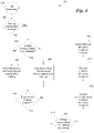
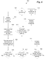
- HEI processing 300 includes various other aspects illustrated in Figs. 4 through 6 and which may also be calculated asynchronously along with the stages shown at 301.
- Transmission/hybrid control module 148 performs the stages shown in Figs. 3 through 6 using a processor or similar computational circuit, programmed or otherwise designed to perform HEI processing as shown and to cause hybrid system 100 to respond accordingly as indicated in the figures and described below.
- HEI processing 300 in Fig. 3 includes calculating a maximum evaluation power level and a minimum evaluation power level (302) thus establishing a range of available power output values.
- the maximum and minimum evaluation power levels generally correspond to operational characteristics of energy storage system 134, eMachine 112, the current power output of engine 102, as well as other related aspects of hybrid system 100. Because the HEI represents the trade-off between burning fuel in the engine versus using electrical energy in eMachine 112, the upper limit of the maximum evaluation power level, in one embodiment, represents the electrical power level required to operate eMachine 112 at a level that would cause it to produce the same mechanical output power that is currently being produced by engine 102 burning fuel to provide a user requested output torque.
- this calculated electrical power value may exceed the maximum power that can be delivered by energy storage system 134 or utilized by the eMachine 112.
- energy storage system 134 can only deliver, at most, some maximum power based on its current state of charge, temperature, and various other operating parameters.
- eMachine 112 can only utilize electrical energy at a given maximum rate based on its design constraints and therefore can only deliver some well-known maximum mechanical output power. Therefore, transmission/hybrid control module 148 can determine the maximum evaluation power level by, for example, using the minimum value of either the discharge power limit of energy storage system 134, the maximum useable input power of eMachine 112, or the power value resulting from converting the mechanical power produced by the engine to an equivalent electrical power at the current user torque request.
- the minimum evaluation power level is determined by calculating a minimum operating consumption power level, such as at idle when the system is under minimal load.
- the transmission/hybrid control module 148 calculates a plurality of motor discharge power values (303) representing the set of electrical energy levels for which a Hybrid Efficiency Index will be calculated.
- the plurality of motor discharge power values is determined by incrementing the power level for each discharge power in the set of values by a preset value or increment over the previous value. The increment may be adjustable and may be dependent on aspects of hybrid system 100 such as the smallest power adjustment to which inverter 132 and eMachine 112 are able to respond to.
- the plurality of discharge power levels is determined by dividing the available range between the maximum and minimum discharge power by a preset number such as 100 or 50.
- the transmission/hybrid control module 148 iterates through the plurality of motor discharge power values (304) calculating the HEI for each motor discharge power value given the current operator torque quest. To calculate the HEI, transmission/hybrid control module 148 calculates an electric motor torque (306) using the current motor discharge power value as the input power in the calculation. In one embodiment, the electric motor torque is calculated by converting the input power from electrical to mechanical energy and dividing by the motor speed. Other suitable calculations may be used as well.
- a reduction in energy storage is also calculated (307) where the stored energy reduction indicates the reduction in available energy that would result from withdrawing the input power from the energy storage device in order to create the calculated electric motor torque.
- the stored energy reduction includes the electric power consumed by the motor while also, for example, taking into account losses in energy storage system 134 resulting from the transfer of energy from energy storage system 134 to eMachine 112. These losses include losses due to heating caused by resistance to the transfer of energy.
- power losses in the batteries can be characterized in terms of resistance, power, and voltage as R ⁇ (P/E) 2 where R is the resistance of the battery pack, P is the input power to eMachine 112 (the power withdrawn from the battery in this case), and E is the input voltage to eMachine 112.
- a similar stored energy reduction calculation is performed using the minimum evaluation power to determine the minimum stored energy reduction. Both the minimum stored energy reduction, and the stored energy reduction are used to calculate a stored energy reduction differential (309).
- An engine torque for the engine is calculated (310) which is reduced by the torque output calculated for the electric motor.
- the engine torque calculation includes the previously calculated electric motor torque calculation from stage 306 indicating that engine 102 reduces its torque output in proportion to the torque produced by eMachine 112.
- both engine 102 and eMachine 112 work together to fulfill the operator power (i.e. torque) request and the motor torque operates as a replacement for some or all of the engine torque output.
- a rate of fuel consumption for engine 102 is calculated at 312 for both the current input power, and the minimum evaluation power.
- Fuel consumption rates for a given engine speed, torque, and output power are generally well characterized by the manufacturer and made available to transmission/hybrid control module 148 from engine control module 146 as engine 102 is operating. These mappings are used by transmission/hybrid control module 148 to determine the quantity of fuel used.
- a fuel usage differential is calculated at 313 by, for example, subtracting the rate of fuel consumption from the minimum evaluation fuel consumption rate determined from the minimum evaluation power.
- the HEI is calculated (315) as the fuel usage differential calculated in stage 313 divided by the stored energy reduction differential calculated in stage 309.
- the calculated Hybrid Efficiency Index is saved (317), for example, at least until an HEI has been calculated for all the motor discharge power values. If more motor discharge power values remain to process (318), the HEI calculation repeats for another motor discharge power value at stage 304.
- the transmission/hybrid control module 148 determines if any of the calculated HEI values saved in stage 317 are higher than a current minimum efficiency threshold (320). If not, calculation of a new set of HEI values is performed and processing begins again at stage 302. Processing the HEI loop may be programmed or otherwise designed to execute multiple times per second, for example 50 times per second, but may be executed more quickly such as 100 times per second or even faster, or less quickly such as five or 10 times per second or slower depending on the embodiment and system constraints. Also, some time lag may be incorporated into the transition from stage 320 to 302 when no HEI values are higher than the minimum efficiency threshold. In some embodiments it may be advantageous to wait some period of time before repeating the HEI calculations for a new set of motor discharge power values.
- the HEI processing 301 completes with adjusting the eMachine 112 input power if applicable. If at least one of the HEI values calculated in stage 315 and saved in stage 317 is higher than the minimum efficiency threshold (320), the transmission/hybrid control module 148 selects the HEI value that is both higher than the minimum efficiency threshold and has the highest input power (321). The input power for the selected HEI value is used by the transmission/hybrid control module 148 as the new input power setting for eMachine 112.
- the transmission/hybrid control module 148 then signals the relevant components of hybrid system 100 such as inverter 132, energy storage system 134, and eMachine 112 to operate eMachine 112 in the electric motor mode generating an output torque substantially equal to the input torque used in the calculation of the selected HEI value.
- engine control module 146 is signaled by the transmission/hybrid control module 148 to reduce engine output torque by the same amount thus trading engine 102 torque for eMachine 112 torque.
- HEI processing then returns to stage 302 where a new set of HEI calculations is made evaluating anew the most efficient trade-off between electrical energy and fuel burn in relation to current requested torque output and the performance constraints of hybrid system 100.
- the calculation of the HEI values for a given set of motor discharge power values is calculated repeatedly during the operation of the hybrid system 100, perhaps multiple times per second in some embodiments.
- other aspects of HEI processing include adjusting the minimum efficiency threshold which operates to select only the best opportunities for using electrical energy (see stage 320) in place of burning fuel in engine 102.
- HEI processing 300 includes adjusting the minimum efficiency threshold (or HEI target) to ensure that regenerative energy is captured and not lost because of inadequate available storage in energy storage system 134.
- HEI processing 300 seeks to ideally maintain the minimum efficiency threshold just low enough so that energy expended over the entire trip or operating cycle is about equal to the regenerative energy captured during the trip.
- mismanagement of power stored in energy storage system 134 may result in the loss of the opportunity to recover energy during a regenerative braking event, for example, in the case where the energy storage system is already full and no further energy can be recovered. Therefore, in one embodiment of HEI processing 300, the minimum efficiency threshold is reduced where energy is being lost in regeneration. Reducing the minimum efficiency threshold has the effect of increasing the likelihood cMachinc 112 will be used because it results in more evaluation power levels from stage 302 translating into candidate HEI values in stage 321 (See Fig. 3 ).
- transmission/hybrid control module 148 determines if a regenerative braking event is starting (401) and if not, processing continues as before. This determination can be made, for example, by detecting torque in transmission 106 coming from wheels 110 through drive train 108. Such an event may occur during vehicle deceleration alone, or when frictional braking is applied as well. Further, such an event may occur anytime a torque is applied to eMachine 112 from the hybrid vehicle drive train 108 and transmission 106.
- transmission/hybrid control module 148 determines whether the energy storage system 134 is fully charged (403), for example by communicating with energy storage system 134 over hybrid data link 202. If energy storage system 134 is fully charged, transmission/hybrid control module 148 calculates the energy that will not be recovered during the regenerative braking event (405). If the energy storage system is not fully charged (403), transmission/hybrid control module 148 calculates the energy that is recovered during the regenerative braking process (407) as torque from transmission 106 spins eMachine 112 operating in the generator mode to produce electric power.
- transmission/hybrid control module 148 calculates whether the energy unrecovered is greater than the energy recovered (410). If not, HEI processing continues at stage 300. If the energy unrecovered is greater than a fraction K of the energy recovered (410) transmission/hybrid control module 148 accesses the previously saved minimum efficiency threshold (412) and reduces the minimum efficiency threshold (413). This reduction may be for example, an incremental reduction by a small scalar value such as 0.1 or 0.5, or some other value. In other embodiments, the reduction may be calculated depending on the current value of the minimum efficiency threshold thus, for example, reducing the minimum efficiency threshold by a greater amount if the value is higher or by a lesser amount if it is lower.
- the modified minimum efficiency threshold is saved by the controller (415) and is useable throughout HEI processing 300 such as in stage 320 when selecting HEI values calculated from the set of evaluation power levels.
- the minimum efficiency threshold may be adjusted using an offset.
- the offset is determined based on maintaining or approximating a desired storage capacity in the energy storage system 134. For example, for embodiment of the energy storage system 134 that includes one or more battery cells, it may be well-known from the battery cell manufacturer that the batteries perform best when kept between, for example, 40% and 70% charged. Therefore an offset may be applied to the minimum efficiency threshold to adjust the threshold lower or higher to maintain this approximate state of charge in energy storage system 134.
- the offset may be incorporated into the operating logic of transmission/hybrid control module 148 if the offset is maintained in place for an extended period of time.
- This process of incorporating the offset may occur automatically, such as by adaptive logic which, for example, automatically includes the offset into the minimum efficiency threshold calculations after the offset has been maintained for a preset number of days, or the incorporation process may be manual manually activated when the logic in the processor or processing circuit reprogrammed or reset by a technician.
- the transmission/hybrid control module 148 observes the energy recaptured and adaptively learns the expected ratio of kinetic energy that can be recovered across the vehicle speed envelope. As the vehicle is moving, the algorithm can use the expected ratio to determine if adequate storage capacity is present at any given time.
- This aspect of HEI processing is also performed by the transmission/hybrid control module 148 and illustrated in Fig. 5 at 500.
- An expected energy recovery is calculated at 501.
- the expected energy recovery is calculated in transmission/hybrid control module 148 by averaging recent recovered energy quotients where the recovered energy quotients are each calculated as the ratio of an actual recovered energy divided by a maximum recoverable energy.
- the maximum recoverable energy can be determined as a function of the mass and velocity of the vehicle, both of which are either made available to transmission/hybrid control module 148 by hybrid system 100, or are calculated by transmission/hybrid control module 148.
- Transmission/hybrid control module 148 determines if the expected energy recovery is greater than the current storage capacity (503). If so, HEI processing continues at 300. If the expected energy recovery is less than the current storage capacity (503) then transmission/hybrid control module 148 checks to determine if the expected energy recovery is greater than the maximum storage capacity in energy storage system 134 (505). If not, HEI processing continues at 300. If the expected energy recovery is greater than the maximum storage capacity (505), the previously saved minimum efficiency threshold is accessed from memory (506) and transmission/hybrid control module 148 reduces the minimum efficiency threshold (508) as discussed above. The reduced minimum efficiency threshold is also saved (509) for use throughout all aspects of HEI processing 300, for example in stages 320, 412, and 506.
- the transmission/hybrid control module 148 seeks to maintain a minimum efficiency threshold that is as high as possible. Energy is extracted from the energy storage system 134 to power the vehicle or assist engine 102 using eMachine 112 at a given power level when the calculated HEI at that power level exceeds the current minimum efficiency threshold. eMachine 112 will continue to provide some or all of the user's torque request until the HEI drops below the current minimum efficiency threshold.
- Transmission/hybrid control module 148 can then calculate the quantity of energy expended during this particular propulsion event, and can also determine how much, if any, of this energy would have been expended if the minimum efficiency threshold had been set to a predetermined evaluation efficiency threshold that is higher than the current minimum efficiency threshold. By comparing the energy expended with the energy that would have been expended at the higher evaluation threshold, transmission/hybrid control module 148 can determine whether a higher minimum efficiency threshold will result in a more judicious use of available electrical power resulting in a higher fuel efficiency.
- the transmission/hybrid control module 148 accesses the previously saved minimum efficiency threshold and a previously saved evaluation efficiency threshold at 602.
- the actual energy usage is calculated based on information obtained from energy storage system 134 during propulsion events (604).
- energy usage is calculated during the propulsion phase by integrating the storage discharge rate over time yielding a value representing an energy usage for the time the HEI was above the minimum efficiency threshold and eMachine 112 was withdrawing power from energy storage system 134.
- the transmission/hybrid control module 148 can then calculate the energy that would have been withdrawn from energy storage system 134 using the higher evaluation threshold (605).
- the higher evaluation threshold is used to determine whether the evaluation threshold would have resulted in higher power expenditures. If the evaluation energy and the actual energy expended are equal (606), HEI processing continues at 300. If the evaluation energy and the actual energy are not equal, transmission/hybrid control module 148 determines if the evaluation energy is greater than the actual energy withdrawn from energy storage system 134 at stage 607. If so, transmission/hybrid control module 148 compares the expected energy recovery with the current storage capacity (609). If the expected energy recovery is not less than the current storage capacity, HEI processing continues at 300.
- the minimum efficiency threshold is increased (611), for example by some incremental amount, by a computed value as discussed above, or set equal to the evaluation threshold, and the newly increased minimum efficiency threshold is saved to the controller memory (613).
- the minimum efficiency threshold is raised because the energy that could have been expended at the higher evaluation threshold is greater than the energy that was expended, and energy storage system 134 can still hold more energy than it expects to recover. Therefore, transmission/hybrid controller 148 is justified in saving a little more energy, using a little less, and thus raises the minimum threshold.
- transmission/hybrid control module 148 evaluates whether the expected energy recovery is greater than or equal to the current storage capacity (615). If not, HEI processing continues at 300. If the expected energy recovery is greater than or equal to the current storage capacity (615), the minimum efficiency threshold and the evaluation threshold are both reduced (616), for example, as discussed above, and the newly reduced thresholds are saved in the memory in transmission/hybrid control module 148 (613) and HEI processing continues at (300). In this case, the actual energy recovered is the same or greater than the current threshold, and energy storage system 134 likely cannot hold the energy the system expects to recover from regeneration. This indicates too much energy is being stored meaning the minimum efficiency threshold should be reduced to increase the likelihood the excess energy will be expended rather than wasted.
Landscapes
- Engineering & Computer Science (AREA)
- Chemical & Material Sciences (AREA)
- Combustion & Propulsion (AREA)
- Transportation (AREA)
- Mechanical Engineering (AREA)
- Automation & Control Theory (AREA)
- Electric Propulsion And Braking For Vehicles (AREA)
- Hybrid Electric Vehicles (AREA)
Claims (12)
- Verfahren (301) zum Steuern eines Hybridsystems (100), das Folgendes umfasst:Berechnen (306; 303) einer Vielzahl von Elektromotor-Ausgangsdrehmoment-Zielniveaus für einen Elektromotorgenerator und einer Vielzahl von Verbrennungsmotor-Ausgangsdrehmoment-Zielniveaus für einen Verbrennungsmotor (102) unter Verwendung einer Steuerung (148); wobei die entsprechende Vielzahl von Elektromotor-Ausgangsdrehmoment-Zielniveaus und die Vielzahl von Verbrennungsmotor-Ausgangsdrehmoment-Zielniveaus zusammen ausreichen, um die aktuelle Bediener-Drehmomentanforderung zu erfüllen, und wobei der Verbrennungsmotor (102) und der Elektromotorgenerator auf die Steuerung (148) ansprechen, und wobei der Verbrennungsmotor (102), der Elektromotorgenerator und die Steuerung (148) in einem Hybridsystem (100) enthalten sind;Berechnen einer Vielzahl von Stromeingangsniveaus unter Verwendung der Steuerung (148), wobei die Stromeingangsniveaus ausreichen, um den Elektromotorgenerator im Elektromotormodus zu betreiben, um die entsprechende Vielzahl von Elektromotor-Ausgangsdrehmoment-Zielniveaus zu erzeugen,wobei die Vielzahl von Elektromotordrehmomenten durch Umwandeln der entsprechenden Vielzahl von Elektromotorleistungsniveaus in ein äquivalentes Niveau an mechanischer Energie und dann Dividieren durch eine Elektromotordrehzahl berechnet wird;Berechnen (315) einer Vielzahl von Wirkungsgradindizes unter Verwendung der Steuerung (148), wobei die Steuerung (148) die Vielzahl von Wirkungsgradindizes anhand der Vielzahl von Verbrennungsmotor-Ausgangsdrehmomentniveaus und der entsprechenden Vielzahl von Elektromotor-Ausgangsniveaus berechnet,Verwenden der Steuerung (148) zum Auswählen (321) eines der Elektromotor-Ausgangsdrehmoment-Zielniveaus und der entsprechenden Verbrennungsmotor-Ausgangszielniveaus, wobei der Wirkungsgradindex für das ausgewählte Elektromotor-Ausgangsdrehmoment-Zielniveau und das entsprechende Verbrennungsmotor-Ausgangszielniveau größer ist als ein von der Steuerung (148) berechneter aktueller minimaler Wirkungsgradschwellenwert;Betreiben (323), unter Verwendung der Steuerung (148), des Elektromotorgenerators zum Erzeugen eines tatsächlichen Elektromotor-Ausgangsdrehmoments, das mit dem ausgewählten Elektromotor-Ausgangsdrehmoment-Zielniveau übereinstimmt; undBetreiben, unter Verwendung der Steuerung (148), des Verbrennungsmotors (102) zum Erzeugen eines tatsächlichen Verbrennungsmotor-Ausgangsdrehmoments, das mit dem ausgewählten Verbrennungsmotor-Ausgangsdrehmomentniveau übereinstimmt,dadurch gekennzeichnet, dassdas Berechnen (315) der Vielzahl von Wirkungsgradindizes ferner Folgendes umfasst:Berechnen (307), unter Verwendung der Steuerung (148), einer Vielzahl von Gespeicherte-Energie-Reduktionswerten, wobei die Vielzahl von Gespeicherte-Energie-Reduktionswerten anhand von entsprechenden Elektromotor-Ausgangsdrehmoment-Zielwerten aus der Vielzahl von Elektromotor-Ausgangsdrehmoment-Zielwerten berechnet wird;Berechnen (309), unter Verwendung der Steuerung (148), einer Vielzahl von Gespeicherte-Energie-Reduktionsdifferenzen, wobei die Gespeicherte-Energie-Reduktionsdifferenzen eine Differenz zwischen entsprechenden Gespeicherte-Energie-Reduktionswerten und einer minimalen Gespeicherte-Energie-Reduktion definieren;Berechnen (312), unter Verwendung der Steuerung (148), einer Vielzahl von Kraftstoffverbrauchsraten, wobei die Vielzahl von Kraftstoffverbrauchsraten anhand von entsprechenden Verbrennungsmotor-Ausgangsdrehmomentwerten aus der Vielzahl von Verbrennungsmotor-Ausgangsdrehmomentwerten berechnet wird;Berechnen einer minimalen Kraftstoffverbrauchsrate unter Verwendung der Steuerung (148);Berechnen (313), unter Verwendung der Steuerung (148), einer Vielzahl von Kraftstoffverbrauchsdifferenzen, wobei die Kraftstoffverbrauchsdifferenzen eine Differenz zwischen entsprechenden Kraftstoffverbrauchsraten und der minimalen Kraftstoffverbrauchsrate definieren; undDividieren der Vielzahl von Kraftstoffverbrauchsdifferenzen durch die entsprechende Vielzahl von Gespeicherte-Energie-Reduktionsdifferenzen.
- Verfahren (301) nach Anspruch 1, wobei das Berechnen der Vielzahl von Wirkungsgradindizes ferner Folgendes umfasst:
Berechnen (302), unter Verwendung der Steuerung (148), einer maximalen Bewertungsleistung und einer minimalen Bewertungsleistung, wobei die Vielzahl von Elektromotor-Ausgangsdrehmoment-Zielniveaus genauso groß wie oder kleiner als die maximale Bewertungsleistung und genauso groß wie oder größer als die minimale Bewertungsleistung ist. - Verfahren (301) nach Anspruch 2, wobei die maximale Bewertungsleistung anhand des Minimums von Folgendem berechnet (302) wird: einer maximalen Speichersystemausgangsleistung für ein Energiespeichersystem, das den Elektromotorgenerator mit Strom versorgt, einer maximalen Elektromotoreingangsleistung und einem elektrischen Strom, der ausreicht, um zu bewirken, dass der Elektromotorgenerator eine Elektromotorausgangsleistung erzeugt, die im Wesentlichen gleich einer aktuellen Verbrennungsmotorausgangsleistung ist.
- Verfahren (301) nach Anspruch 3, wobei die Anzahl der von der Steuerung (148) berechneten Elektromotor-Ausgangsleistungsniveaus gleich oder kleiner als 50 ist;oder wobei die Anzahl der von der Steuerung (148) berechneten Elektromotor-Ausgangsleistungsniveaus zwischen 50 und 100 liegt;oder wobei die Anzahl der von der Steuerung (148) berechneten Ausgangsleistungsniveaus gleich oder größer als 100 ist.
- Verfahren (301) nach Anspruch 1, wobei die Vielzahl von Gespeicherte-Energie-Reduktionswerten durch Berechnen einer Vielzahl von Reduktionen der gespeicherten Energie berechnet werden, die sich aus dem Betrieb des Elektromotorgenerators ergeben würden, um die Vielzahl von entsprechenden Elektromotor-Ausgangsdrehmoment-Zielniveaus zu erzeugen.
- Verfahren (301) nach Anspruch 1 oder 5, wobei die Vielzahl von Gespeicherte-Energie-Reduktionswerten durch Berechnen einer Vielzahl von Stromeingangsniveaus unter Verwendung der Steuerung (148) berechnet werden, wobei die Stromeingangsniveaus ausreichen, um den Elektromotorgenerator im Elektromotormodus zu betreiben, um die entsprechende Vielzahl von Elektromotor-Ausgangsdrehmoment-Zielniveaus zu erzeugen.
- Verfahren (301) nach Anspruch 5 oder 6, wobei das Berechnen der Vielzahl von Gespeicherte-Energie-Reduktionswerten das Berechnen eines entsprechenden Wärmeenergieverlusts, der durch einen Energiespeichersystemwiderstand eines mit dem Elektromotorgenerator elektrisch verbundenen Energiespeichersystems verursacht wird, einer Energiespeichersystemspannung und eines Energiespeichersystemstroms umfasst.
- Verfahren (301) nach Anspruch 1, wobei das Berechnen (312) der Vielzahl von Kraftstoffverbrauchsraten das Abbilden einer Verbrennungsmotordrehzahl und eines Verbrennungsmotordrehmoments entsprechend dem Verbrennungsmotor-Ausgangsdrehmomentniveau auf eine entsprechende resultierende Kraftstoffverbrauchsrate umfasst;
und wobei optional das Abbilden einer Verbrennungsmotordrehzahl und eines Verbrennungsmotordrehmoments anhand eines in der Steuerung (148) gespeicherten Kennfeldes durchgeführt wird. - Verfahren (301) nach einem vorhergehenden Anspruch, wobei das Berechnen (315) der Vielzahl von Wirkungsgradindizes ferner Folgendes umfasst:Berechnen (501) einer erwarteten Energierückgewinnung unter Verwendung der Steuerung (148), wobei die erwartete Energierückgewinnung eine von dem im Generatormodus betriebenen Elektromotorgenerator zurückzugewinnende Energiemenge darstellt;und optional Berechnen eines erwarteten Energierückgewinnungsverhältnisses durch Mitteln von zwei oder mehr Quotienten von rückgewonnener Energie miteinander, wobei die zwei oder mehr Quotienten von zurückgewonnener Energie als ein Verhältnis einer tatsächlich zurückgewonnenen Energie dividiert durch eine maximal zurückgewinnbare Energie berechnet werden.
- Verfahren (301) nach einem der vorhergehenden Ansprüche, das ferner Folgendes umfasst:Berechnen einer minimalen Wirkungsgradschwelle unter Verwendung der Steuerung (148), wobei die minimale Wirkungsgradschwelle anhand einer durch den Elektromotorgenerator zurückgewonnenen Energie und einer durch den Elektromotorgenerator nicht zurückgewonnenen Energie berechnet wird, wobei der Elektromotorgenerator im Generatormodus arbeitet; undReduzieren (413) der minimalen Wirkungsgradschwelle unter Verwendung der Steuerung (148), wenn die nicht zurückgewonnene Energie mindestens einen Bruchteil der zurückgewonnenen Energie überschreitet.
- Verfahren (301) nach Anspruch 10, das ferner das Senken der minimalen Wirkungsgradschwelle unter Verwendung der Steuerung (148) umfasst, wenn die erwartete Energierückgewinnung größer ist als eine aktuelle Elektroenergiespeicherkapazität in dem Hybridsystem (100) und die erwartete Energierückgewinnung eine maximale Speicherkapazität nicht überschreitet.
- Verfahren (301) nach Anspruch 9, wobei das Berechnen der erwarteten Energierückgewinnung die Nutzung einer aktuellen kinetischen Energie des Fahrzeugs und des erwarteten Energierückgewinnungsverhältnisses einschließt.
Applications Claiming Priority (2)
| Application Number | Priority Date | Filing Date | Title |
|---|---|---|---|
| US201361782476P | 2013-03-14 | 2013-03-14 | |
| PCT/US2014/020532 WO2014158848A1 (en) | 2013-03-14 | 2014-03-05 | System and method for optimizing power consumption in a hybrid electric vehicle |
Publications (3)
| Publication Number | Publication Date |
|---|---|
| EP2969689A1 EP2969689A1 (de) | 2016-01-20 |
| EP2969689A4 EP2969689A4 (de) | 2017-08-02 |
| EP2969689B1 true EP2969689B1 (de) | 2022-12-07 |
Family
ID=51625066
Family Applications (1)
| Application Number | Title | Priority Date | Filing Date |
|---|---|---|---|
| EP14775950.0A Active EP2969689B1 (de) | 2013-03-14 | 2014-03-05 | System und verfahren zum optimieren des stromverbrauchs in einem hybriden elektrofahrzeug |
Country Status (7)
| Country | Link |
|---|---|
| US (1) | US9561791B2 (de) |
| EP (1) | EP2969689B1 (de) |
| KR (1) | KR102160399B1 (de) |
| CN (1) | CN105189233B (de) |
| AU (2) | AU2014241789B2 (de) |
| CA (2) | CA2898505C (de) |
| WO (1) | WO2014158848A1 (de) |
Families Citing this family (10)
| Publication number | Priority date | Publication date | Assignee | Title |
|---|---|---|---|---|
| JP6404548B2 (ja) * | 2013-07-22 | 2018-10-10 | トヨタ自動車株式会社 | 車両 |
| FR3028109B1 (fr) * | 2014-11-03 | 2020-01-24 | Renault S.A.S | Procede de gestion de l'etat de charge d'une batterie de traction d'un vehicule hybride. |
| DE102016217946A1 (de) * | 2016-09-20 | 2018-03-22 | Voith Patent Gmbh | Hybridfahrzeug |
| US10252710B2 (en) * | 2017-05-10 | 2019-04-09 | Toyota Motor Engineering & Manufacturing North America, Inc. | Utilizing missed prediction |
| CN107878445B (zh) * | 2017-11-06 | 2019-01-18 | 吉林大学 | 一种考虑电池性能衰减的混合动力汽车能量优化管理方法 |
| EP3670240A1 (de) * | 2018-12-20 | 2020-06-24 | Ningbo Geely Automobile Research & Development Co. Ltd. | System und verfahren zur steuerung des energieverbrauchs in einem fahrzeug |
| CN110135632B (zh) * | 2019-04-29 | 2022-11-25 | 吉林大学 | 基于路径信息的phev自适应最优能量管理方法 |
| CN113370965B (zh) * | 2021-06-21 | 2022-09-20 | 同济大学 | 一种混合动力汽车的工作点选择及调整方法 |
| CN113627720B (zh) * | 2021-06-30 | 2023-04-28 | 四川大学 | 基于电能替代的综合园区风光储系统配置方法 |
| WO2024041740A1 (en) * | 2022-08-26 | 2024-02-29 | Volvo Truck Corporation | A propulsion system for a heavy-duty vehicle, a heavy-duty vehicle and a method for controlling a propulsion system |
Family Cites Families (11)
| Publication number | Priority date | Publication date | Assignee | Title |
|---|---|---|---|---|
| US5820172A (en) * | 1997-02-27 | 1998-10-13 | Ford Global Technologies, Inc. | Method for controlling energy flow in a hybrid electric vehicle |
| US7482767B2 (en) * | 2004-01-30 | 2009-01-27 | Solomon Technologies, Inc. | Regenerative motor propulsion systems |
| US7530413B2 (en) * | 2004-08-13 | 2009-05-12 | General Motors Corporation | Reducing torque disturbances and improving fuel economy in hybrid electric powertrains |
| US7826939B2 (en) | 2006-09-01 | 2010-11-02 | Azure Dynamics, Inc. | Method, apparatus, signals, and medium for managing power in a hybrid vehicle |
| JP2009040094A (ja) * | 2007-08-06 | 2009-02-26 | Toyota Motor Corp | ハイブリッド式の車両の出力制御装置、及び方法 |
| US8285431B2 (en) * | 2007-11-03 | 2012-10-09 | GM Global Technology Operations LLC | Optimal selection of hybrid range state and/or input speed with a blended braking system in a hybrid electric vehicle |
| US8140204B2 (en) * | 2007-12-10 | 2012-03-20 | Ford Global Technologies, Llc | Charge depleting energy management strategy for plug-in hybrid electric vehicles |
| JP5447245B2 (ja) * | 2010-07-13 | 2014-03-19 | 日産自動車株式会社 | ハイブリッド車両 |
| DE102011003425B4 (de) | 2011-02-01 | 2015-01-08 | Henkel Ag & Co. Kgaa | Verwendung einer härtbaren Zusammensetzung mit kombinierten Stabilisatoren |
| GB2487732B (en) * | 2011-02-01 | 2017-10-25 | Jaguar Land Rover Ltd | Hybrid electric vehicle controller and method of controlling a hybrid electric vehicle |
| GB2492765A (en) * | 2011-07-11 | 2013-01-16 | Jaguar Cars | Hybrid vehicle controller verifies that engine torque corresponds to demanded torque |
-
2014
- 2014-03-05 CA CA2898505A patent/CA2898505C/en active Active
- 2014-03-05 AU AU2014241789A patent/AU2014241789B2/en active Active
- 2014-03-05 EP EP14775950.0A patent/EP2969689B1/de active Active
- 2014-03-05 KR KR1020157028875A patent/KR102160399B1/ko not_active Expired - Fee Related
- 2014-03-05 WO PCT/US2014/020532 patent/WO2014158848A1/en not_active Ceased
- 2014-03-05 CN CN201480015328.9A patent/CN105189233B/zh active Active
- 2014-03-05 CA CA3100999A patent/CA3100999C/en active Active
-
2015
- 2015-08-31 US US14/840,078 patent/US9561791B2/en not_active Expired - Fee Related
-
2016
- 2016-07-05 AU AU2016204650A patent/AU2016204650B2/en active Active
Also Published As
| Publication number | Publication date |
|---|---|
| CA2898505A1 (en) | 2014-10-02 |
| CA3100999A1 (en) | 2014-10-02 |
| KR20150128979A (ko) | 2015-11-18 |
| CA3100999C (en) | 2023-03-07 |
| CN105189233A (zh) | 2015-12-23 |
| AU2014241789A1 (en) | 2015-08-20 |
| EP2969689A4 (de) | 2017-08-02 |
| AU2014241789B2 (en) | 2016-07-28 |
| US20150367838A1 (en) | 2015-12-24 |
| KR102160399B1 (ko) | 2020-09-29 |
| CN105189233B (zh) | 2019-06-18 |
| US9561791B2 (en) | 2017-02-07 |
| AU2016204650A1 (en) | 2016-07-21 |
| CA2898505C (en) | 2021-11-09 |
| AU2016204650B2 (en) | 2018-07-05 |
| EP2969689A1 (de) | 2016-01-20 |
| WO2014158848A1 (en) | 2014-10-02 |
Similar Documents
| Publication | Publication Date | Title |
|---|---|---|
| US9561791B2 (en) | System and method for optimizing power consumption in a hybrid electric vehicle | |
| CN109693578B (zh) | 一种燃料电池车整车功率分配控制方法和系统 | |
| AU2014241787B2 (en) | System and method for power management during regeneration mode in hybrid electric vehicles | |
| EP4458631B1 (de) | Verfahren und vorrichtung zur fahrzeugbeschleunigungssteuerung, fahrzeug und speichermedium | |
| CN111361450A (zh) | 一种增程器控制方法、装置、设备及存储介质 | |
| CN112550086A (zh) | 一种车辆能量管理方法、装置、车辆及存储介质 | |
| CN110341494A (zh) | 一种vcu系统保护扭矩控制方法、充放电控制方法 | |
| CN112117818A (zh) | 一种车载光伏系统及其控制方法、装置和存储介质 | |
| WO2025161047A1 (zh) | 车载电池充电功率控制方法、装置、车辆及介质 | |
| CN114714984B (zh) | Soc平衡控制方法、整车控制器、设备及可读存储介质 | |
| CN117922309B (zh) | 电机扭矩限制方法、装置、控制器及计算机可读存储介质 | |
| CN114340963A (zh) | 混合动力车辆中的扭矩分配的管理方法 | |
| CN118024966A (zh) | 燃料电池汽车的能量管理方法及装置 | |
| JP4495003B2 (ja) | 鉄道車両の蓄電装置暖機方法及び装置 | |
| JP7810127B2 (ja) | 充放電管理システム | |
| CN120621078A (zh) | 车辆驱动扭矩分配方法、装置、电子设备及可读存储介质 | |
| CN107302241A (zh) | Dcdc转换器控制方法及装置 | |
| CN118888923A (zh) | 电动汽车热管理系统及其热管理方法 | |
| CN112550271A (zh) | 一种混合动力汽车及其功率输出控制方法和控制装置 | |
| CN117416258A (zh) | 车辆的电池温度控制方法及装置 |
Legal Events
| Date | Code | Title | Description |
|---|---|---|---|
| PUAI | Public reference made under article 153(3) epc to a published international application that has entered the european phase |
Free format text: ORIGINAL CODE: 0009012 |
|
| 17P | Request for examination filed |
Effective date: 20150715 |
|
| AK | Designated contracting states |
Kind code of ref document: A1 Designated state(s): AL AT BE BG CH CY CZ DE DK EE ES FI FR GB GR HR HU IE IS IT LI LT LU LV MC MK MT NL NO PL PT RO RS SE SI SK SM TR |
|
| AX | Request for extension of the european patent |
Extension state: BA ME |
|
| DAX | Request for extension of the european patent (deleted) | ||
| RIC1 | Information provided on ipc code assigned before grant |
Ipc: B60W 10/08 20060101ALI20170201BHEP Ipc: B60W 10/06 20060101ALI20170201BHEP Ipc: B60W 20/00 20160101AFI20170201BHEP Ipc: B60W 10/04 20060101ALI20170201BHEP |
|
| A4 | Supplementary search report drawn up and despatched |
Effective date: 20170704 |
|
| RIC1 | Information provided on ipc code assigned before grant |
Ipc: B60W 10/08 20060101ALI20170628BHEP Ipc: B60W 10/04 20060101ALI20170628BHEP Ipc: B60W 10/06 20060101ALI20170628BHEP Ipc: B60W 20/00 20160101AFI20170628BHEP |
|
| STAA | Information on the status of an ep patent application or granted ep patent |
Free format text: STATUS: EXAMINATION IS IN PROGRESS |
|
| 17Q | First examination report despatched |
Effective date: 20190802 |
|
| GRAP | Despatch of communication of intention to grant a patent |
Free format text: ORIGINAL CODE: EPIDOSNIGR1 |
|
| STAA | Information on the status of an ep patent application or granted ep patent |
Free format text: STATUS: GRANT OF PATENT IS INTENDED |
|
| INTG | Intention to grant announced |
Effective date: 20220713 |
|
| GRAS | Grant fee paid |
Free format text: ORIGINAL CODE: EPIDOSNIGR3 |
|
| GRAA | (expected) grant |
Free format text: ORIGINAL CODE: 0009210 |
|
| STAA | Information on the status of an ep patent application or granted ep patent |
Free format text: STATUS: THE PATENT HAS BEEN GRANTED |
|
| AK | Designated contracting states |
Kind code of ref document: B1 Designated state(s): AL AT BE BG CH CY CZ DE DK EE ES FI FR GB GR HR HU IE IS IT LI LT LU LV MC MK MT NL NO PL PT RO RS SE SI SK SM TR |
|
| REG | Reference to a national code |
Ref country code: GB Ref legal event code: FG4D |
|
| REG | Reference to a national code |
Ref country code: CH Ref legal event code: EP Ref country code: AT Ref legal event code: REF Ref document number: 1536141 Country of ref document: AT Kind code of ref document: T Effective date: 20221215 |
|
| REG | Reference to a national code |
Ref country code: DE Ref legal event code: R096 Ref document number: 602014085745 Country of ref document: DE |
|
| REG | Reference to a national code |
Ref country code: IE Ref legal event code: FG4D |
|
| REG | Reference to a national code |
Ref country code: LT Ref legal event code: MG9D |
|
| REG | Reference to a national code |
Ref country code: NL Ref legal event code: MP Effective date: 20221207 |
|
| PG25 | Lapsed in a contracting state [announced via postgrant information from national office to epo] |
Ref country code: SE Free format text: LAPSE BECAUSE OF FAILURE TO SUBMIT A TRANSLATION OF THE DESCRIPTION OR TO PAY THE FEE WITHIN THE PRESCRIBED TIME-LIMIT Effective date: 20221207 Ref country code: NO Free format text: LAPSE BECAUSE OF FAILURE TO SUBMIT A TRANSLATION OF THE DESCRIPTION OR TO PAY THE FEE WITHIN THE PRESCRIBED TIME-LIMIT Effective date: 20230307 Ref country code: LT Free format text: LAPSE BECAUSE OF FAILURE TO SUBMIT A TRANSLATION OF THE DESCRIPTION OR TO PAY THE FEE WITHIN THE PRESCRIBED TIME-LIMIT Effective date: 20221207 Ref country code: FI Free format text: LAPSE BECAUSE OF FAILURE TO SUBMIT A TRANSLATION OF THE DESCRIPTION OR TO PAY THE FEE WITHIN THE PRESCRIBED TIME-LIMIT Effective date: 20221207 Ref country code: ES Free format text: LAPSE BECAUSE OF FAILURE TO SUBMIT A TRANSLATION OF THE DESCRIPTION OR TO PAY THE FEE WITHIN THE PRESCRIBED TIME-LIMIT Effective date: 20221207 |
|
| REG | Reference to a national code |
Ref country code: AT Ref legal event code: MK05 Ref document number: 1536141 Country of ref document: AT Kind code of ref document: T Effective date: 20221207 |
|
| PG25 | Lapsed in a contracting state [announced via postgrant information from national office to epo] |
Ref country code: RS Free format text: LAPSE BECAUSE OF FAILURE TO SUBMIT A TRANSLATION OF THE DESCRIPTION OR TO PAY THE FEE WITHIN THE PRESCRIBED TIME-LIMIT Effective date: 20221207 Ref country code: PL Free format text: LAPSE BECAUSE OF FAILURE TO SUBMIT A TRANSLATION OF THE DESCRIPTION OR TO PAY THE FEE WITHIN THE PRESCRIBED TIME-LIMIT Effective date: 20221207 Ref country code: LV Free format text: LAPSE BECAUSE OF FAILURE TO SUBMIT A TRANSLATION OF THE DESCRIPTION OR TO PAY THE FEE WITHIN THE PRESCRIBED TIME-LIMIT Effective date: 20221207 Ref country code: HR Free format text: LAPSE BECAUSE OF FAILURE TO SUBMIT A TRANSLATION OF THE DESCRIPTION OR TO PAY THE FEE WITHIN THE PRESCRIBED TIME-LIMIT Effective date: 20221207 Ref country code: GR Free format text: LAPSE BECAUSE OF FAILURE TO SUBMIT A TRANSLATION OF THE DESCRIPTION OR TO PAY THE FEE WITHIN THE PRESCRIBED TIME-LIMIT Effective date: 20230308 |
|
| P01 | Opt-out of the competence of the unified patent court (upc) registered |
Effective date: 20230517 |
|
| PG25 | Lapsed in a contracting state [announced via postgrant information from national office to epo] |
Ref country code: NL Free format text: LAPSE BECAUSE OF FAILURE TO SUBMIT A TRANSLATION OF THE DESCRIPTION OR TO PAY THE FEE WITHIN THE PRESCRIBED TIME-LIMIT Effective date: 20221207 |
|
| PG25 | Lapsed in a contracting state [announced via postgrant information from national office to epo] |
Ref country code: SM Free format text: LAPSE BECAUSE OF FAILURE TO SUBMIT A TRANSLATION OF THE DESCRIPTION OR TO PAY THE FEE WITHIN THE PRESCRIBED TIME-LIMIT Effective date: 20221207 Ref country code: RO Free format text: LAPSE BECAUSE OF FAILURE TO SUBMIT A TRANSLATION OF THE DESCRIPTION OR TO PAY THE FEE WITHIN THE PRESCRIBED TIME-LIMIT Effective date: 20221207 Ref country code: PT Free format text: LAPSE BECAUSE OF FAILURE TO SUBMIT A TRANSLATION OF THE DESCRIPTION OR TO PAY THE FEE WITHIN THE PRESCRIBED TIME-LIMIT Effective date: 20230410 Ref country code: EE Free format text: LAPSE BECAUSE OF FAILURE TO SUBMIT A TRANSLATION OF THE DESCRIPTION OR TO PAY THE FEE WITHIN THE PRESCRIBED TIME-LIMIT Effective date: 20221207 Ref country code: CZ Free format text: LAPSE BECAUSE OF FAILURE TO SUBMIT A TRANSLATION OF THE DESCRIPTION OR TO PAY THE FEE WITHIN THE PRESCRIBED TIME-LIMIT Effective date: 20221207 Ref country code: AT Free format text: LAPSE BECAUSE OF FAILURE TO SUBMIT A TRANSLATION OF THE DESCRIPTION OR TO PAY THE FEE WITHIN THE PRESCRIBED TIME-LIMIT Effective date: 20221207 |
|
| PG25 | Lapsed in a contracting state [announced via postgrant information from national office to epo] |
Ref country code: SK Free format text: LAPSE BECAUSE OF FAILURE TO SUBMIT A TRANSLATION OF THE DESCRIPTION OR TO PAY THE FEE WITHIN THE PRESCRIBED TIME-LIMIT Effective date: 20221207 Ref country code: IS Free format text: LAPSE BECAUSE OF FAILURE TO SUBMIT A TRANSLATION OF THE DESCRIPTION OR TO PAY THE FEE WITHIN THE PRESCRIBED TIME-LIMIT Effective date: 20230407 Ref country code: AL Free format text: LAPSE BECAUSE OF FAILURE TO SUBMIT A TRANSLATION OF THE DESCRIPTION OR TO PAY THE FEE WITHIN THE PRESCRIBED TIME-LIMIT Effective date: 20221207 |
|
| REG | Reference to a national code |
Ref country code: DE Ref legal event code: R097 Ref document number: 602014085745 Country of ref document: DE |
|
| PLBE | No opposition filed within time limit |
Free format text: ORIGINAL CODE: 0009261 |
|
| STAA | Information on the status of an ep patent application or granted ep patent |
Free format text: STATUS: NO OPPOSITION FILED WITHIN TIME LIMIT |
|
| PG25 | Lapsed in a contracting state [announced via postgrant information from national office to epo] |
Ref country code: MC Free format text: LAPSE BECAUSE OF FAILURE TO SUBMIT A TRANSLATION OF THE DESCRIPTION OR TO PAY THE FEE WITHIN THE PRESCRIBED TIME-LIMIT Effective date: 20221207 Ref country code: DK Free format text: LAPSE BECAUSE OF FAILURE TO SUBMIT A TRANSLATION OF THE DESCRIPTION OR TO PAY THE FEE WITHIN THE PRESCRIBED TIME-LIMIT Effective date: 20221207 |
|
| REG | Reference to a national code |
Ref country code: CH Ref legal event code: PL |
|
| 26N | No opposition filed |
Effective date: 20230908 |
|
| GBPC | Gb: european patent ceased through non-payment of renewal fee |
Effective date: 20230307 |
|
| PG25 | Lapsed in a contracting state [announced via postgrant information from national office to epo] |
Ref country code: SI Free format text: LAPSE BECAUSE OF FAILURE TO SUBMIT A TRANSLATION OF THE DESCRIPTION OR TO PAY THE FEE WITHIN THE PRESCRIBED TIME-LIMIT Effective date: 20221207 |
|
| REG | Reference to a national code |
Ref country code: BE Ref legal event code: MM Effective date: 20230331 |
|
| PG25 | Lapsed in a contracting state [announced via postgrant information from national office to epo] |
Ref country code: LU Free format text: LAPSE BECAUSE OF NON-PAYMENT OF DUE FEES Effective date: 20230305 |
|
| REG | Reference to a national code |
Ref country code: IE Ref legal event code: MM4A |
|
| PG25 | Lapsed in a contracting state [announced via postgrant information from national office to epo] |
Ref country code: GB Free format text: LAPSE BECAUSE OF NON-PAYMENT OF DUE FEES Effective date: 20230307 |
|
| PG25 | Lapsed in a contracting state [announced via postgrant information from national office to epo] |
Ref country code: LI Free format text: LAPSE BECAUSE OF NON-PAYMENT OF DUE FEES Effective date: 20230331 Ref country code: IE Free format text: LAPSE BECAUSE OF NON-PAYMENT OF DUE FEES Effective date: 20230305 Ref country code: GB Free format text: LAPSE BECAUSE OF NON-PAYMENT OF DUE FEES Effective date: 20230307 Ref country code: FR Free format text: LAPSE BECAUSE OF NON-PAYMENT OF DUE FEES Effective date: 20230331 Ref country code: CH Free format text: LAPSE BECAUSE OF NON-PAYMENT OF DUE FEES Effective date: 20230331 |
|
| PG25 | Lapsed in a contracting state [announced via postgrant information from national office to epo] |
Ref country code: BE Free format text: LAPSE BECAUSE OF NON-PAYMENT OF DUE FEES Effective date: 20230331 |
|
| PG25 | Lapsed in a contracting state [announced via postgrant information from national office to epo] |
Ref country code: IT Free format text: LAPSE BECAUSE OF FAILURE TO SUBMIT A TRANSLATION OF THE DESCRIPTION OR TO PAY THE FEE WITHIN THE PRESCRIBED TIME-LIMIT Effective date: 20221207 |
|
| PG25 | Lapsed in a contracting state [announced via postgrant information from national office to epo] |
Ref country code: BG Free format text: LAPSE BECAUSE OF FAILURE TO SUBMIT A TRANSLATION OF THE DESCRIPTION OR TO PAY THE FEE WITHIN THE PRESCRIBED TIME-LIMIT Effective date: 20221207 |
|
| PG25 | Lapsed in a contracting state [announced via postgrant information from national office to epo] |
Ref country code: BG Free format text: LAPSE BECAUSE OF FAILURE TO SUBMIT A TRANSLATION OF THE DESCRIPTION OR TO PAY THE FEE WITHIN THE PRESCRIBED TIME-LIMIT Effective date: 20221207 |
|
| PGFP | Annual fee paid to national office [announced via postgrant information from national office to epo] |
Ref country code: DE Payment date: 20250327 Year of fee payment: 12 |
|
| PG25 | Lapsed in a contracting state [announced via postgrant information from national office to epo] |
Ref country code: CY Free format text: LAPSE BECAUSE OF FAILURE TO SUBMIT A TRANSLATION OF THE DESCRIPTION OR TO PAY THE FEE WITHIN THE PRESCRIBED TIME-LIMIT; INVALID AB INITIO Effective date: 20140305 |
|
| PG25 | Lapsed in a contracting state [announced via postgrant information from national office to epo] |
Ref country code: HU Free format text: LAPSE BECAUSE OF FAILURE TO SUBMIT A TRANSLATION OF THE DESCRIPTION OR TO PAY THE FEE WITHIN THE PRESCRIBED TIME-LIMIT; INVALID AB INITIO Effective date: 20140305 |
|
| PG25 | Lapsed in a contracting state [announced via postgrant information from national office to epo] |
Ref country code: TR Free format text: LAPSE BECAUSE OF FAILURE TO SUBMIT A TRANSLATION OF THE DESCRIPTION OR TO PAY THE FEE WITHIN THE PRESCRIBED TIME-LIMIT Effective date: 20221207 |