EP2969552B1 - Apparatus comprising component including structures for determinant loading and a method for using the apparatus - Google Patents
Apparatus comprising component including structures for determinant loading and a method for using the apparatus Download PDFInfo
- Publication number
- EP2969552B1 EP2969552B1 EP13826830.5A EP13826830A EP2969552B1 EP 2969552 B1 EP2969552 B1 EP 2969552B1 EP 13826830 A EP13826830 A EP 13826830A EP 2969552 B1 EP2969552 B1 EP 2969552B1
- Authority
- EP
- European Patent Office
- Prior art keywords
- component
- ceramic matrix
- matrix composite
- stacked plies
- reinforcement material
- Prior art date
- Legal status (The legal status is an assumption and is not a legal conclusion. Google has not performed a legal analysis and makes no representation as to the accuracy of the status listed.)
- Active
Links
Images


Classifications
-
- B—PERFORMING OPERATIONS; TRANSPORTING
- B32—LAYERED PRODUCTS
- B32B—LAYERED PRODUCTS, i.e. PRODUCTS BUILT-UP OF STRATA OF FLAT OR NON-FLAT, e.g. CELLULAR OR HONEYCOMB, FORM
- B32B18/00—Layered products essentially comprising ceramics, e.g. refractory products
-
- G—PHYSICS
- G01—MEASURING; TESTING
- G01B—MEASURING LENGTH, THICKNESS OR SIMILAR LINEAR DIMENSIONS; MEASURING ANGLES; MEASURING AREAS; MEASURING IRREGULARITIES OF SURFACES OR CONTOURS
- G01B5/00—Measuring arrangements characterised by the use of mechanical techniques
- G01B5/28—Measuring arrangements characterised by the use of mechanical techniques for measuring roughness or irregularity of surfaces
-
- C—CHEMISTRY; METALLURGY
- C04—CEMENTS; CONCRETE; ARTIFICIAL STONE; CERAMICS; REFRACTORIES
- C04B—LIME, MAGNESIA; SLAG; CEMENTS; COMPOSITIONS THEREOF, e.g. MORTARS, CONCRETE OR LIKE BUILDING MATERIALS; ARTIFICIAL STONE; CERAMICS; REFRACTORIES; TREATMENT OF NATURAL STONE
- C04B2235/00—Aspects relating to ceramic starting mixtures or sintered ceramic products
- C04B2235/70—Aspects relating to sintered or melt-casted ceramic products
- C04B2235/94—Products characterised by their shape
- C04B2235/945—Products containing grooves, cuts, recesses or protusions
-
- C—CHEMISTRY; METALLURGY
- C04—CEMENTS; CONCRETE; ARTIFICIAL STONE; CERAMICS; REFRACTORIES
- C04B—LIME, MAGNESIA; SLAG; CEMENTS; COMPOSITIONS THEREOF, e.g. MORTARS, CONCRETE OR LIKE BUILDING MATERIALS; ARTIFICIAL STONE; CERAMICS; REFRACTORIES; TREATMENT OF NATURAL STONE
- C04B2235/00—Aspects relating to ceramic starting mixtures or sintered ceramic products
- C04B2235/70—Aspects relating to sintered or melt-casted ceramic products
- C04B2235/96—Properties of ceramic products, e.g. mechanical properties such as strength, toughness, wear resistance
- C04B2235/963—Surface properties, e.g. surface roughness
-
- C—CHEMISTRY; METALLURGY
- C04—CEMENTS; CONCRETE; ARTIFICIAL STONE; CERAMICS; REFRACTORIES
- C04B—LIME, MAGNESIA; SLAG; CEMENTS; COMPOSITIONS THEREOF, e.g. MORTARS, CONCRETE OR LIKE BUILDING MATERIALS; ARTIFICIAL STONE; CERAMICS; REFRACTORIES; TREATMENT OF NATURAL STONE
- C04B2237/00—Aspects relating to ceramic laminates or to joining of ceramic articles with other articles by heating
- C04B2237/30—Composition of layers of ceramic laminates or of ceramic or metallic articles to be joined by heating, e.g. Si substrates
- C04B2237/32—Ceramic
- C04B2237/34—Oxidic
- C04B2237/341—Silica or silicates
-
- C—CHEMISTRY; METALLURGY
- C04—CEMENTS; CONCRETE; ARTIFICIAL STONE; CERAMICS; REFRACTORIES
- C04B—LIME, MAGNESIA; SLAG; CEMENTS; COMPOSITIONS THEREOF, e.g. MORTARS, CONCRETE OR LIKE BUILDING MATERIALS; ARTIFICIAL STONE; CERAMICS; REFRACTORIES; TREATMENT OF NATURAL STONE
- C04B2237/00—Aspects relating to ceramic laminates or to joining of ceramic articles with other articles by heating
- C04B2237/30—Composition of layers of ceramic laminates or of ceramic or metallic articles to be joined by heating, e.g. Si substrates
- C04B2237/32—Ceramic
- C04B2237/34—Oxidic
- C04B2237/343—Alumina or aluminates
-
- C—CHEMISTRY; METALLURGY
- C04—CEMENTS; CONCRETE; ARTIFICIAL STONE; CERAMICS; REFRACTORIES
- C04B—LIME, MAGNESIA; SLAG; CEMENTS; COMPOSITIONS THEREOF, e.g. MORTARS, CONCRETE OR LIKE BUILDING MATERIALS; ARTIFICIAL STONE; CERAMICS; REFRACTORIES; TREATMENT OF NATURAL STONE
- C04B2237/00—Aspects relating to ceramic laminates or to joining of ceramic articles with other articles by heating
- C04B2237/30—Composition of layers of ceramic laminates or of ceramic or metallic articles to be joined by heating, e.g. Si substrates
- C04B2237/32—Ceramic
- C04B2237/36—Non-oxidic
- C04B2237/363—Carbon
-
- C—CHEMISTRY; METALLURGY
- C04—CEMENTS; CONCRETE; ARTIFICIAL STONE; CERAMICS; REFRACTORIES
- C04B—LIME, MAGNESIA; SLAG; CEMENTS; COMPOSITIONS THEREOF, e.g. MORTARS, CONCRETE OR LIKE BUILDING MATERIALS; ARTIFICIAL STONE; CERAMICS; REFRACTORIES; TREATMENT OF NATURAL STONE
- C04B2237/00—Aspects relating to ceramic laminates or to joining of ceramic articles with other articles by heating
- C04B2237/30—Composition of layers of ceramic laminates or of ceramic or metallic articles to be joined by heating, e.g. Si substrates
- C04B2237/32—Ceramic
- C04B2237/36—Non-oxidic
- C04B2237/365—Silicon carbide
-
- C—CHEMISTRY; METALLURGY
- C04—CEMENTS; CONCRETE; ARTIFICIAL STONE; CERAMICS; REFRACTORIES
- C04B—LIME, MAGNESIA; SLAG; CEMENTS; COMPOSITIONS THEREOF, e.g. MORTARS, CONCRETE OR LIKE BUILDING MATERIALS; ARTIFICIAL STONE; CERAMICS; REFRACTORIES; TREATMENT OF NATURAL STONE
- C04B2237/00—Aspects relating to ceramic laminates or to joining of ceramic articles with other articles by heating
- C04B2237/30—Composition of layers of ceramic laminates or of ceramic or metallic articles to be joined by heating, e.g. Si substrates
- C04B2237/32—Ceramic
- C04B2237/38—Fiber or whisker reinforced
-
- C—CHEMISTRY; METALLURGY
- C04—CEMENTS; CONCRETE; ARTIFICIAL STONE; CERAMICS; REFRACTORIES
- C04B—LIME, MAGNESIA; SLAG; CEMENTS; COMPOSITIONS THEREOF, e.g. MORTARS, CONCRETE OR LIKE BUILDING MATERIALS; ARTIFICIAL STONE; CERAMICS; REFRACTORIES; TREATMENT OF NATURAL STONE
- C04B2237/00—Aspects relating to ceramic laminates or to joining of ceramic articles with other articles by heating
- C04B2237/50—Processing aspects relating to ceramic laminates or to the joining of ceramic articles with other articles by heating
- C04B2237/70—Forming laminates or joined articles comprising layers of a specific, unusual thickness
- C04B2237/704—Forming laminates or joined articles comprising layers of a specific, unusual thickness of one or more of the ceramic layers or articles
-
- C—CHEMISTRY; METALLURGY
- C04—CEMENTS; CONCRETE; ARTIFICIAL STONE; CERAMICS; REFRACTORIES
- C04B—LIME, MAGNESIA; SLAG; CEMENTS; COMPOSITIONS THEREOF, e.g. MORTARS, CONCRETE OR LIKE BUILDING MATERIALS; ARTIFICIAL STONE; CERAMICS; REFRACTORIES; TREATMENT OF NATURAL STONE
- C04B2237/00—Aspects relating to ceramic laminates or to joining of ceramic articles with other articles by heating
- C04B2237/50—Processing aspects relating to ceramic laminates or to the joining of ceramic articles with other articles by heating
- C04B2237/76—Forming laminates or joined articles comprising at least one member in the form other than a sheet or disc, e.g. two tubes or a tube and a sheet or disc
-
- C—CHEMISTRY; METALLURGY
- C04—CEMENTS; CONCRETE; ARTIFICIAL STONE; CERAMICS; REFRACTORIES
- C04B—LIME, MAGNESIA; SLAG; CEMENTS; COMPOSITIONS THEREOF, e.g. MORTARS, CONCRETE OR LIKE BUILDING MATERIALS; ARTIFICIAL STONE; CERAMICS; REFRACTORIES; TREATMENT OF NATURAL STONE
- C04B2237/00—Aspects relating to ceramic laminates or to joining of ceramic articles with other articles by heating
- C04B2237/50—Processing aspects relating to ceramic laminates or to the joining of ceramic articles with other articles by heating
- C04B2237/84—Joining of a first substrate with a second substrate at least partially inside the first substrate, where the bonding area is at the inside of the first substrate, e.g. one tube inside another tube
-
- C—CHEMISTRY; METALLURGY
- C04—CEMENTS; CONCRETE; ARTIFICIAL STONE; CERAMICS; REFRACTORIES
- C04B—LIME, MAGNESIA; SLAG; CEMENTS; COMPOSITIONS THEREOF, e.g. MORTARS, CONCRETE OR LIKE BUILDING MATERIALS; ARTIFICIAL STONE; CERAMICS; REFRACTORIES; TREATMENT OF NATURAL STONE
- C04B2237/00—Aspects relating to ceramic laminates or to joining of ceramic articles with other articles by heating
- C04B2237/50—Processing aspects relating to ceramic laminates or to the joining of ceramic articles with other articles by heating
- C04B2237/86—Joining of two substrates at their largest surfaces, one surface being complete joined and covered, the other surface not, e.g. a small plate joined at it's largest surface on top of a larger plate
-
- F—MECHANICAL ENGINEERING; LIGHTING; HEATING; WEAPONS; BLASTING
- F01—MACHINES OR ENGINES IN GENERAL; ENGINE PLANTS IN GENERAL; STEAM ENGINES
- F01D—NON-POSITIVE DISPLACEMENT MACHINES OR ENGINES, e.g. STEAM TURBINES
- F01D5/00—Blades; Blade-carrying members; Heating, heat-insulating, cooling or antivibration means on the blades or the members
- F01D5/12—Blades
- F01D5/28—Selecting particular materials; Particular measures relating thereto; Measures against erosion or corrosion
- F01D5/282—Selecting composite materials, e.g. blades with reinforcing filaments
-
- F—MECHANICAL ENGINEERING; LIGHTING; HEATING; WEAPONS; BLASTING
- F05—INDEXING SCHEMES RELATING TO ENGINES OR PUMPS IN VARIOUS SUBCLASSES OF CLASSES F01-F04
- F05D—INDEXING SCHEME FOR ASPECTS RELATING TO NON-POSITIVE-DISPLACEMENT MACHINES OR ENGINES, GAS-TURBINES OR JET-PROPULSION PLANTS
- F05D2300/00—Materials; Properties thereof
- F05D2300/60—Properties or characteristics given to material by treatment or manufacturing
- F05D2300/603—Composites; e.g. fibre-reinforced
- F05D2300/6033—Ceramic matrix composites [CMC]
-
- F—MECHANICAL ENGINEERING; LIGHTING; HEATING; WEAPONS; BLASTING
- F05—INDEXING SCHEMES RELATING TO ENGINES OR PUMPS IN VARIOUS SUBCLASSES OF CLASSES F01-F04
- F05D—INDEXING SCHEME FOR ASPECTS RELATING TO NON-POSITIVE-DISPLACEMENT MACHINES OR ENGINES, GAS-TURBINES OR JET-PROPULSION PLANTS
- F05D2300/00—Materials; Properties thereof
- F05D2300/70—Treatment or modification of materials
- F05D2300/702—Reinforcement
Definitions
- the place of the insert is the tang of the blade.
- the blade is mounted on a turbine rotor by engaging the tang in a housing of corresponding shape formed in the periphery of the rotor.
- the material of the insert is preferably the same as the material of the matrix.
- the apparatus comprises a first component having a ceramic exterior surface and including a primary surface region and a plurality of secondary surface regions protruding from the primary surface region, as well as a second component positioned to contact at least one of the secondary surface regions and spaced from the primary surface region to define at least one determinant load path between the first and second components.
- the apparatus can be further defined by one or more of particular types of ceramic matrices, particular surface roughness profiles, and particular spacings between the first and second components or regions thereof.
- a component 100 that generally includes a main body portion 102 and one or more load bearing portions 104, with the main body portion 102 defining a primary surface region 102a and each of the load bearing portions 104 defining a secondary surface region 104a.
- the primary surface region 102a and the secondary surface regions 104a together form an exterior surface 100a of the first component 100.
- the first component 100 includes a plurality of the load bearing portions 104, which in turn provide the exterior surface 100a with a plurality of the secondary surface regions 104a.
- the first component 100 may include two, three or four or more of the load bearing portions 104 which each define one of the secondary surface regions 104a.
- the secondary surface regions 104a protrude from the primary surface region 102a (e.g., along the "y" axis).
- each load bearing portion 104 is structured such that the secondary surface region 104a projects from the primary surface region 102a to a height h (also referred to herein as the "protrusion height") sufficient to define a determinant load path through one or more of the load bearing portions 104 when another component is brought into contact with the secondary surface regions 104a of the load bearing portions 104.
- h also referred to herein as the "protrusion height”
- the second component 200 engaged with the first component 100 to form a multi-component apparatus 202 according to one form of the invention.
- the second component 200 is structured to contact the secondary surface regions 104a defined by the load bearing portions 104 of the first component 100, and is also structured to be spaced apart from the primary surface region 102a defined by the main body portion 102 of the first component 100.
- the gap or space g ( FIG. 3 ) defined between the second component 200 and the primary surface region 102a of the first component 100 may be used as an air gap in a turbomachinery component (e.g., a rotary turbine blade) to provide a pathway for cooling air flow.
- a turbomachinery component e.g., a rotary turbine blade
- a load applied to the second component 200 may be selectively transmitted to the load bearing portions 104 of the first component 100 generally along predetermined load paths 204.
- a load applied to the first component 100 may similarly be selectively transmitted to the second component 200 via the load bearing portions 104.
- the exterior surface 100a of the first component 100 is formed of a ceramic material.
- the first component 100 is provided as a ceramic matrix composite component.
- the ceramic material forming the exterior surface 100a of the first component 100 is a ceramic matrix material. Examples of suitable ceramic matrix materials from which the exterior surface 100a may be formed include silicon carbide, alumina, silica, mullite, other known ceramic matrix materials, or a combination thereof.
- the ceramic material forming the exterior surface 100a of the first component 100 may include one or more ceramic materials such as ceramic environmental protection coatings, ceramic thermal barrier coatings, other known ceramic materials, or a combination thereof.
- the exterior surface 100a may be formed by one or more suitable processes or application techniques such as plasma spraying, physical vapor deposition, chemical vapor deposition, chemical vapor infiltration, directed vapor deposition, dipping, spraying, electroplating, other known formation or application processes, or a combination thereof.
- suitable processes or application techniques such as plasma spraying, physical vapor deposition, chemical vapor deposition, chemical vapor infiltration, directed vapor deposition, dipping, spraying, electroplating, other known formation or application processes, or a combination thereof.
- the exterior surface 100a of the first component 100 generally has a surface roughness profile that can be characterized by one more parameters known and understood by those of ordinary skill in the art. Examples of such parameters include one or more height parameters (e.g., the average roughness R ⁇ ; the root mean squared roughness Rrms; maximum peak height Rt ; skewness Rsk ; the kurtosis Rku; or a combination thereof), one or more spacing parameters (e.g., mean peak spacing Smp ), or a combination thereof.
- height parameters e.g., the average roughness R ⁇ ; the root mean squared roughness Rrms; maximum peak height Rt ; skewness Rsk ; the kurtosis Rku; or a combination thereof
- spacing parameters e.g., mean peak spacing Smp
- the surface roughness profile of the exterior surface 100a can be measured or otherwise analyzed by any suitable contact or noncontact technique using one or more suitable instruments (e.g., 2D profilometers, 3D profilometers, interferometric microscopes, confocal microscopes, structured light projectors, stereoscopic microscopes, line triangulation lasers, or a combination thereof).
- suitable instruments e.g., 2D profilometers, 3D profilometers, interferometric microscopes, confocal microscopes, structured light projectors, stereoscopic microscopes, line triangulation lasers, or a combination thereof.
- the protrusion height h of one or more of the load bearing portions 104 is selected to be greater than the maximum peak height Rt of the surface roughness profile in the primary surface region 102a of the exterior surface 100a.
- a spacing distance d between adjacent load bearing portions 104 may be greater than a mean peak spacing Smp of the surface roughness profile in the primary surface region 102a of the exterior surface 100a.
- a length dimension l and/or width dimension w of the load bearing portion 104 may be greater than a mean peak spacing Smp of the surface roughness profile in the primary surface region 102a of the exterior surface 100a.
- the overall shapes or primary forms of the primary and secondary surface regions 102a and 104a generally correspond to the primary form of the exterior surface 100a of the first component 100.
- the primary form of the exterior surface 100a of the first component 100 is substantially planar generally along the "x" and "z" axes.
- the primary surface region 102a of the main body portion 102 and the secondary surface region 104a of each load bearing portion 104 are also substantially planar generally along the "x" and "z” axes.
- the exterior surface 100a of the first component 100 may be curved about the "x,” “y” and/or "z” axes. For example, referring to FIG.
- the exterior surface 100a of the first component 100 may be curved about the "z" axis such that the exterior surface 100a has a concave form.
- the second component 200 may be positioned adjacent the exterior surface 100a and may have an exterior surface having a curved form (e.g., a convex form) corresponding to the curved form of the first component 100.
- the first component 100 can have a different (e.g., lower) coefficient of thermal expansion relative to the second component 200.
- the second component 200 can be formed of a metallic material. Because the load bearing portions 104 are structured as exemplarily described above, adequate engagement or mating of the exterior surface 100a of the first component 100 with an exterior surface of the second component 200 can be ensured over a wide range of temperatures, even when the components 100 and 200 have different coefficients of thermal expansion.
- the first component 100 may include a preform structure 400 formed of a reinforcing material and a ceramic matrix material (not shown) surrounding, either completely or only partially, the preform structure 400.
- the ceramic matrix material may be provided by one or more suitable processes or application techniques such as, for example, plasma spraying, physical vapor deposition, chemical vapor deposition, chemical vapor infiltration, directed vapor deposition, dipping, spraying, electroplating, or a combination thereof.
- the preform structure 400 includes a plurality of plies (e.g., plies 402a, 402b, 402c, 402d and 402e) of a reinforcement material arranged in a stacked configuration.
- suitable reinforcement materials include carbon, silicon carbide, alumina, silica, and mullite, or a combination thereof.
- the preform structure 400 further includes one or more inserts such as, for example, inserts 404 and 406.
- the inserts 404 and 406 are provided as plies of reinforcement material, which may be the same as or different from the reinforcement material of the plies 402a-402e. As exemplarily illustrated in FIG.
- the insert 404 is interposed between a pair of the adjacent plies 402c and 402d of the reinforcement material
- the insert 406 is interposed between a pair of the adjacent plies 402d and 402e of the reinforcement material.
- one or more inserts may be provided anywhere within or on the preform structure 400.
- two or more inserts may be interposed between an adjacent pair of the plies (e.g., plies 402d and 402e.
- at least one insert may be disposed on an uppermost or outermost ply of the stack of plies (e.g., ply 402e).
- the preform structure 400 defines an upper/exterior surface 400a.
- the inserts 404 and 406 cause a portion of the exterior surface 400a (e.g., surface portion 408a) to protrude from another portion of the exterior surface 400a (e.g., surface portion 410a).
- the location of the surface portion 410a defined by the exterior surface 400a corresponds to the location of the primary surface region 102a defined by the first component 100.
- the location of the surface portion 408a defined by the exterior surface 400a corresponds to the location of the secondary surface region 104a defined by the first component 100.
- the load bearing portions 104 of the first component 100 is defined by the portions of the preform structure 400 adjacent to the inserts 404, 406.
- the first component 100 may include a preform structure 500 formed of a reinforcing material and a ceramic matrix material (not shown) surrounding, either completely or only partially, the preform structure 500.
- the preform structure 500 includes a plurality of plies (e.g., plies 502a, 502b, 502c, 502d and 502e) of a reinforcement material arranged in a stacked configuration.
- suitable reinforcement materials include carbon, silicon carbide, alumina, silica, and mullite, or a combination thereof.
- the preform structure 500 is configured similar to the preform structure 400 illustrated and described above with regard to FIG. 4 .
- the preform structure 500 includes an insert 504 configured as a pad formed of, for example, chopped fiber. As exemplarily illustrated in FIG. 5 , the pad 504 is interposed between a pair of the adjacent plies 502c and 502d of the reinforcement material. However, it should be appreciated that one or more pads or inserts may be provided anywhere within or on the preform structure 500. For example, another pad 504 and/or one or more of the inserts 404, 406 may be interposed between another pair of the adjacent plies and/or disposed on an uppermost or outermost ply of the stack of plies (e.g., ply 502e).
- the preform structure 500 defines an upper/exterior surface 500a.
- the pad 504 causes a portion of the exterior surface 500a (e.g., surface portion 508a) to protrude from another portion of the exterior surface 500a (e.g., surface portion 510a).
- the location of the surface portion 510a defined by the exterior surface 500a corresponds to the location of the primary surface region 102a defined by the first component 100.
- the location of the surface portion 508a defined by the exterior surface 500a corresponds to the location of the secondary surface region 104a defined by the first component 100.
- the load bearing portions 104 of the first component 100 include the portions of the preform structure 500 adjacent to the pad 504.
- the first component 100 may include a preform structure 600 formed of a reinforcing material and a ceramic matrix material (not shown) surrounding, either completely or only partially, the preform structure 600.
- the preform structure 600 includes a plurality of plies (e.g., plies 602a, 602b, 602c, 602d and 602e) of a reinforcement material arranged in a stacked configuration. Examples of suitable reinforcement materials include carbon, silicon carbide, alumina, silica, and mullite, or a combination thereof.
- the preform structure 600 is configured similar to the preform structures 400 and 500 illustrated and described above with regard to FIGS. 4 and 5 . However, unlike the preform structures 400 and 500 including inserts or pads interposed between adjacent plies of the reinforcement material, the preform structure 600 includes one or more bumps 604 formed along the upper/exterior surface 600a.
- a ceramic matrix material surrounds the preform structure 600.
- the ceramic matrix material is applied by any process or technique (e.g., a chemical vapor infiltration process) suitable to form one or more bumps or protrusions, such as the bump 604, along the upper/exterior surface 600a.
- the bumps 604 define a protruding portion of the exterior surface 600a (e.g., surface portion 608a) that protrudes from another portion of the exterior surface 600a (e.g., surface portion 610a).
- the location of the surface portion 610a defined by the exterior surface 600a corresponds to the location of the primary surface region 102a defined by the first component 100
- the location of the surface portion 608a or bump 604 defined by the exterior surface 600a corresponds to the location of the secondary surface region 104a defined by the first component 100.
- the region of the ceramic matrix material forming the one or more bumps 604 corresponds to the load bearing portions 104 of the first component 100.
- the process used to provide the ceramic matrix material e.g., a chemical vapor infiltration process
- a component 100 can be provided with one or more load bearing portions 104 structured to define a predetermined load path at one or more locations along the first component 100 when another component (e.g., the second component 200) is brought into contact with the exterior surface 100a of the first component 100.
- the exemplary process or technique 700 may include, for example, the step 702 of interpreting a model of an apparatus, the step 704 of determining a location for a load path between components in the apparatus, and the step 706 of fabricating the component 100 with at least one load bearing portion at a location corresponding to the load path.
- suitable processes or techniques for determining where to locate one or more load bearing portions 104 along the first component 100 are also contemplated.
- an apparatus may be provided as defined in claim 1.
- the exterior surface (100a) of the ceramic matrix composite first component (100) may have a surface roughness profile, and a width of each of the secondary surface regions (104a) may be greater than a mean peak spacing of the surface roughness profile.
- the exterior surface (100a) of the ceramic matrix composite first component (100) may have a surface roughness profile wherein a distance between adjacent ones of the secondary surface regions (104a) is greater than the mean peak spacing of the surface roughness profile.
- the ceramic matrix composite apparatus may further comprise a ceramic matrix material surrounding the plurality of stacked plies (402), and at least one insert (404) interposed between an adjacent pair of the plurality of stacked plies (402) at a location corresponding to at least one of the secondary surface regions (104a).
- the ceramic matrix composite apparatus may further comprise a plurality of the inserts (404).
- the ceramic matrix composite apparatus may further comprise a plurality of inserts (404), wherein the plurality of inserts (404) comprises a first of the inserts (404) interposed between a first adjacent pair of the plurality of stacked plies (402) at a location corresponding to the at least one of the secondary surface regions (104a), and a second of the inserts (404) interposed between a second adjacent pair of the plurality of stacked plies (402) at a location corresponding to the at least one of the secondary surface regions (104a).
- At least one insert (404) may include a reinforcement material that is the same as a reinforcement material of at least one of the plurality of stacked plies (402).
- the coefficient of thermal expansion of the ceramic matrix composite first component (100) may be different from a coefficient of thermal expansion of the second component (200).
- At least a portion of the exterior surface (100a) of the ceramic matrix composite first component (100) may have at least one form selected from the group consisting of: a planar form and a curved form. At least a portion of the exterior surface (100a) of the ceramic matrix composite first component (100) may have at least one form selected from the group consisting of: a planar form and a curved form. At least the portion of the exterior surface (100a) of the ceramic matrix composite first component (100) may be concave, and an exterior surface of the second component (200) facing the concave portion of the ceramic matrix composite first component (100) may be convex.
- a method may be provided as defined in claim 11.
- fabricating of the ceramic matrix composite first component (100) may include forming a preform structure comprising a reinforcement material, and infiltrating the preform structure with matrix material.
- the preform structure may comprise a plurality of stacked plies (402) of the reinforcement material, and the fabricating may further comprise positioning an insert (404) between at least two of the plurality of stacked plies (402) at a location corresponding to the load bearing portion.
- the fabricating of the ceramic matrix composite first component (100) may include forming a preform structure comprising a plurality of stacked plies (402) of reinforcement material, and positioning an insert (404) between at least two of the plurality of stacked plies (402) at a location corresponding to the load bearing portion.
Landscapes
- Chemical & Material Sciences (AREA)
- Engineering & Computer Science (AREA)
- Ceramic Engineering (AREA)
- Physics & Mathematics (AREA)
- General Physics & Mathematics (AREA)
- Compositions Of Oxide Ceramics (AREA)
- Sliding-Contact Bearings (AREA)
- Structures Of Non-Positive Displacement Pumps (AREA)
Description
- Many apparatuses or components thereof, such as but not limited to ceramic components, bear loads in use. When the apparatus comprises multiple components, the load may be transferred from one load-bearing component to another load-bearing component. This transfer of load can cause problems, including cracking or mechanical failure, when it is not properly controlled with respect to the portions of the components to or from which the load is transferred. Such control is not readily achieved in structures and apparatuses currently known in the art, leading to a variety of shortcomings and disadvantages. Thus, there is a need for further technical contribution to this field.
US2011/311368 discloses a blade made of CMC material. It consists out of a plurality of stacked plies of fiber reinforcements that are infiltrated with a ceramic matrix. One ceramic insert can be interposed between the plies. The place of the insert is the tang of the blade. The blade is mounted on a turbine rotor by engaging the tang in a housing of corresponding shape formed in the periphery of the rotor. The material of the insert is preferably the same as the material of the matrix. - The apparatus comprises a first component having a ceramic exterior surface and including a primary surface region and a plurality of secondary surface regions protruding from the primary surface region, as well as a second component positioned to contact at least one of the secondary surface regions and spaced from the primary surface region to define at least one determinant load path between the first and second components. In some aspects, the apparatus can be further defined by one or more of particular types of ceramic matrices, particular surface roughness profiles, and particular spacings between the first and second components or regions thereof.
-
-
FIG. 1 is a perspective view of a component including structures for determinant loading according to one form of the invention, as shown somewhat schematically. -
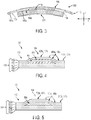
FIG. 2 is a perspective view of the component shown inFIG. 1 and a second component illustrating determinant loading therebetween. -
FIG. 3 is a sectional view of an apparatus including two components according to another form of the invention illustrating determinant loading therebetween. -
FIGS. 4 to 6 are partial sectional views illustrating exemplary embodiments of the component shown inFIG. 1 . -
FIG. 7 is a flow chart illustrating an exemplary embodiment of a process of forming the component shown inFIG. 1 . - For the purposes of promoting an understanding of the principles of the invention, reference will now be made to the embodiments illustrated in the drawings and specific language will be used to describe the same. It will nevertheless be understood that no limitation of the scope of the invention is hereby intended. Any alterations and further modifications in the described embodiments, and any further applications of the principles of the invention as described herein are contemplated as would normally occur to one skilled in the art to which the invention relates.
- Referring to
FIG. 1 , shown therein is acomponent 100 that generally includes amain body portion 102 and one or moreload bearing portions 104, with themain body portion 102 defining aprimary surface region 102a and each of theload bearing portions 104 defining asecondary surface region 104a. Theprimary surface region 102a and thesecondary surface regions 104a together form anexterior surface 100a of thefirst component 100. - The
first component 100 includes a plurality of theload bearing portions 104, which in turn provide theexterior surface 100a with a plurality of thesecondary surface regions 104a. As should be appreciated, thefirst component 100 may include two, three or four or more of theload bearing portions 104 which each define one of thesecondary surface regions 104a. As will be discussed in greater detail below, thesecondary surface regions 104a protrude from theprimary surface region 102a (e.g., along the "y" axis). In one embodiment, eachload bearing portion 104 is structured such that thesecondary surface region 104a projects from theprimary surface region 102a to a height h (also referred to herein as the "protrusion height") sufficient to define a determinant load path through one or more of theload bearing portions 104 when another component is brought into contact with thesecondary surface regions 104a of theload bearing portions 104. - Referring to
FIG. 2 , shown therein is asecond component 200 engaged with thefirst component 100 to form amulti-component apparatus 202 according to one form of the invention. In the illustrated embodiment, thesecond component 200 is structured to contact thesecondary surface regions 104a defined by theload bearing portions 104 of thefirst component 100, and is also structured to be spaced apart from theprimary surface region 102a defined by themain body portion 102 of thefirst component 100. In one embodiment, the gap or space g (FIG. 3 ) defined between thesecond component 200 and theprimary surface region 102a of thefirst component 100 may be used as an air gap in a turbomachinery component (e.g., a rotary turbine blade) to provide a pathway for cooling air flow. As should be appreciated, a load applied to thesecond component 200 may be selectively transmitted to theload bearing portions 104 of thefirst component 100 generally alongpredetermined load paths 204. As should also be appreciated, a load applied to thefirst component 100 may similarly be selectively transmitted to thesecond component 200 via theload bearing portions 104. - Referring back to
FIG. 1 , theexterior surface 100a of thefirst component 100 is formed of a ceramic material. Thefirst component 100 is provided as a ceramic matrix composite component. The ceramic material forming theexterior surface 100a of thefirst component 100 is a ceramic matrix material. Examples of suitable ceramic matrix materials from which theexterior surface 100a may be formed include silicon carbide, alumina, silica, mullite, other known ceramic matrix materials, or a combination thereof. In other embodiments, the ceramic material forming theexterior surface 100a of thefirst component 100 may include one or more ceramic materials such as ceramic environmental protection coatings, ceramic thermal barrier coatings, other known ceramic materials, or a combination thereof. Additionally, theexterior surface 100a may be formed by one or more suitable processes or application techniques such as plasma spraying, physical vapor deposition, chemical vapor deposition, chemical vapor infiltration, directed vapor deposition, dipping, spraying, electroplating, other known formation or application processes, or a combination thereof. - The
exterior surface 100a of thefirst component 100 generally has a surface roughness profile that can be characterized by one more parameters known and understood by those of ordinary skill in the art. Examples of such parameters include one or more height parameters (e.g., the average roughness Rα; the root mean squared roughness Rrms; maximum peak height Rt; skewness Rsk; the kurtosis Rku; or a combination thereof), one or more spacing parameters (e.g., mean peak spacing Smp), or a combination thereof. The surface roughness profile of theexterior surface 100a can be measured or otherwise analyzed by any suitable contact or noncontact technique using one or more suitable instruments (e.g., 2D profilometers, 3D profilometers, interferometric microscopes, confocal microscopes, structured light projectors, stereoscopic microscopes, line triangulation lasers, or a combination thereof). - In one embodiment, the protrusion height h of one or more of the
load bearing portions 104 is selected to be greater than the maximum peak height Rt of the surface roughness profile in theprimary surface region 102a of theexterior surface 100a. In another embodiment, a spacing distance d between adjacent load bearing portions 104 (as measured along the "x" axis and/or the "z" axis) may be greater than a mean peak spacing Smp of the surface roughness profile in theprimary surface region 102a of theexterior surface 100a. In another embodiment, a length dimension l and/or width dimension w of the load bearing portion 104 (e.g., as measured long the "x" axis and/or the "z" axis) may be greater than a mean peak spacing Smp of the surface roughness profile in theprimary surface region 102a of theexterior surface 100a. With themulti-component apparatus 202 constructed as exemplarily described above, the likelihood that thesecond component 200 will contact theload bearing portions 104 at thesecondary surface regions 104a is substantially increased, while the likelihood that thesecond component 200 will contact themain body portion 102 at theprimary surface region 102a is substantially eliminated or significantly reduced. Consequently, theload bearing portions 104 can be constructed to provide desired engagement of thesecondary surface regions 104a of thefirst component 100 with thesecond component 200. - In one embodiment, the overall shapes or primary forms of the primary and
secondary surface regions exterior surface 100a of thefirst component 100. For example, as illustrated inFIGS. 1 and 2 , the primary form of theexterior surface 100a of thefirst component 100 is substantially planar generally along the "x" and "z" axes. Accordingly, theprimary surface region 102a of themain body portion 102 and thesecondary surface region 104a of eachload bearing portion 104 are also substantially planar generally along the "x" and "z" axes. However, in other embodiments, theexterior surface 100a of thefirst component 100 may be curved about the "x," "y" and/or "z" axes. For example, referring toFIG. 3 , theexterior surface 100a of thefirst component 100 may be curved about the "z" axis such that theexterior surface 100a has a concave form. As also shown inFIG. 3 , thesecond component 200 may be positioned adjacent theexterior surface 100a and may have an exterior surface having a curved form (e.g., a convex form) corresponding to the curved form of thefirst component 100. - In some embodiments, the
first component 100 can have a different (e.g., lower) coefficient of thermal expansion relative to thesecond component 200. For example, in embodiments where thefirst component 100 is formed of a ceramic material, thesecond component 200 can be formed of a metallic material. Because theload bearing portions 104 are structured as exemplarily described above, adequate engagement or mating of theexterior surface 100a of thefirst component 100 with an exterior surface of thesecond component 200 can be ensured over a wide range of temperatures, even when thecomponents - Having described the general structures associated with the
first component 100 and thesecond component 200, exemplary constructions of thefirst component 100 according to various embodiments of the invention will now be discussed with reference toFIGS. 4 to 6 . - Referring to
FIG. 4 , in one embodiment, thefirst component 100 may include apreform structure 400 formed of a reinforcing material and a ceramic matrix material (not shown) surrounding, either completely or only partially, thepreform structure 400. The ceramic matrix material may be provided by one or more suitable processes or application techniques such as, for example, plasma spraying, physical vapor deposition, chemical vapor deposition, chemical vapor infiltration, directed vapor deposition, dipping, spraying, electroplating, or a combination thereof. - In the illustrated embodiment, the
preform structure 400 includes a plurality of plies (e.g.,plies preform structure 400 further includes one or more inserts such as, for example,inserts inserts plies 402a-402e. As exemplarily illustrated inFIG. 4 , theinsert 404 is interposed between a pair of theadjacent plies insert 406 is interposed between a pair of theadjacent plies preform structure 400. For example, two or more inserts may be interposed between an adjacent pair of the plies (e.g., plies 402d and 402e. In another example, at least one insert may be disposed on an uppermost or outermost ply of the stack of plies (e.g., ply 402e). - As exemplarily shown in
FIG. 4 , thepreform structure 400 defines an upper/exterior surface 400a. When incorporated within thepreform structure 400, theinserts exterior surface 400a (e.g.,surface portion 408a) to protrude from another portion of theexterior surface 400a (e.g.,surface portion 410a). After the ceramic matrix material is provided to surround thepreform structure 400, the location of thesurface portion 410a defined by theexterior surface 400a corresponds to the location of theprimary surface region 102a defined by thefirst component 100. Likewise, the location of thesurface portion 408a defined by theexterior surface 400a corresponds to the location of thesecondary surface region 104a defined by thefirst component 100. Thus, theload bearing portions 104 of thefirst component 100 is defined by the portions of thepreform structure 400 adjacent to theinserts - Referring to
FIG. 5 , in one embodiment, thefirst component 100 may include apreform structure 500 formed of a reinforcing material and a ceramic matrix material (not shown) surrounding, either completely or only partially, thepreform structure 500. In the illustrated embodiment, thepreform structure 500 includes a plurality of plies (e.g., plies 502a, 502b, 502c, 502d and 502e) of a reinforcement material arranged in a stacked configuration. Examples of suitable reinforcement materials include carbon, silicon carbide, alumina, silica, and mullite, or a combination thereof. In many respects, thepreform structure 500 is configured similar to thepreform structure 400 illustrated and described above with regard toFIG. 4 . However, unlike thepreform structure 400 including theinserts preform structure 500 includes aninsert 504 configured as a pad formed of, for example, chopped fiber. As exemplarily illustrated inFIG. 5 , thepad 504 is interposed between a pair of theadjacent plies preform structure 500. For example, anotherpad 504 and/or one or more of theinserts - Additionally, similar to the
preform structure 400, thepreform structure 500 defines an upper/exterior surface 500a. When incorporated within thepreform structure 500, thepad 504 causes a portion of theexterior surface 500a (e.g.,surface portion 508a) to protrude from another portion of theexterior surface 500a (e.g.,surface portion 510a). After the ceramic matrix material is provided to surround thepreform structure 500, the location of thesurface portion 510a defined by theexterior surface 500a corresponds to the location of theprimary surface region 102a defined by thefirst component 100. Likewise, the location of thesurface portion 508a defined by theexterior surface 500a corresponds to the location of thesecondary surface region 104a defined by thefirst component 100. Thus, theload bearing portions 104 of thefirst component 100 include the portions of thepreform structure 500 adjacent to thepad 504. - Referring to
FIG. 6 , in one embodiment, thefirst component 100 may include apreform structure 600 formed of a reinforcing material and a ceramic matrix material (not shown) surrounding, either completely or only partially, thepreform structure 600. In the illustrated embodiment, thepreform structure 600 includes a plurality of plies (e.g., plies 602a, 602b, 602c, 602d and 602e) of a reinforcement material arranged in a stacked configuration. Examples of suitable reinforcement materials include carbon, silicon carbide, alumina, silica, and mullite, or a combination thereof. In many respects, thepreform structure 600 is configured similar to thepreform structures FIGS. 4 and 5 . However, unlike thepreform structures preform structure 600 includes one ormore bumps 604 formed along the upper/exterior surface 600a. - In the illustrated embodiment of the
preform structure 600, a ceramic matrix material surrounds thepreform structure 600. In one embodiment, the ceramic matrix material is applied by any process or technique (e.g., a chemical vapor infiltration process) suitable to form one or more bumps or protrusions, such as thebump 604, along the upper/exterior surface 600a. Thebumps 604 define a protruding portion of theexterior surface 600a (e.g.,surface portion 608a) that protrudes from another portion of theexterior surface 600a (e.g.,surface portion 610a). After the ceramic matrix material 602 is applied to thepreform structure 500, the location of thesurface portion 610a defined by theexterior surface 600a corresponds to the location of theprimary surface region 102a defined by thefirst component 100, and the location of thesurface portion 608a or bump 604 defined by theexterior surface 600a corresponds to the location of thesecondary surface region 104a defined by thefirst component 100. Thus, the region of the ceramic matrix material forming the one ormore bumps 604 corresponds to theload bearing portions 104 of thefirst component 100. In one embodiment, the process used to provide the ceramic matrix material (e.g., a chemical vapor infiltration process) may form relativelysmall surface asperities 612 that are sized smaller than thebump 604. The cause of these relativelysmaller surface asperities 612 can arise from the use of tooling employed during the chemical vapor infiltration process. Thesesurface asperities 612 may form part of theprimary surface region 102a of thefirst component 100. - As exemplarily described above, a
component 100 can be provided with one or moreload bearing portions 104 structured to define a predetermined load path at one or more locations along thefirst component 100 when another component (e.g., the second component 200) is brought into contact with theexterior surface 100a of thefirst component 100. With reference toFIG. 7 , illustrated therein is an exemplary process ortechnique 700 for determining where to locate one or more of theload bearing portions 104 along thefirst component 100. The exemplary process ortechnique 700 may include, for example, thestep 702 of interpreting a model of an apparatus, thestep 704 of determining a location for a load path between components in the apparatus, and the step 706 of fabricating thecomponent 100 with at least one load bearing portion at a location corresponding to the load path. However, it should be understood that other suitable processes or techniques for determining where to locate one or moreload bearing portions 104 along thefirst component 100 are also contemplated. - In a first aspect, an apparatus may be provided as defined in
claim 1. - Alternatively or in addition, the exterior surface (100a) of the ceramic matrix composite first component (100) may have a surface roughness profile, and a width of each of the secondary surface regions (104a) may be greater than a mean peak spacing of the surface roughness profile. The exterior surface (100a) of the ceramic matrix composite first component (100) may have a surface roughness profile wherein a distance between adjacent ones of the secondary surface regions (104a) is greater than the mean peak spacing of the surface roughness profile.
- Alternatively or in addition, the ceramic matrix composite apparatus may further comprise a ceramic matrix material surrounding the plurality of stacked plies (402), and at least one insert (404) interposed between an adjacent pair of the plurality of stacked plies (402) at a location corresponding to at least one of the secondary surface regions (104a). The ceramic matrix composite apparatus may further comprise a plurality of the inserts (404). The ceramic matrix composite apparatus may further comprise a plurality of inserts (404), wherein the plurality of inserts (404) comprises a first of the inserts (404) interposed between a first adjacent pair of the plurality of stacked plies (402) at a location corresponding to the at least one of the secondary surface regions (104a), and a second of the inserts (404) interposed between a second adjacent pair of the plurality of stacked plies (402) at a location corresponding to the at least one of the secondary surface regions (104a). At least one insert (404) may include a reinforcement material that is the same as a reinforcement material of at least one of the plurality of stacked plies (402).
- Alternatively or in addition, the coefficient of thermal expansion of the ceramic matrix composite first component (100) may be different from a coefficient of thermal expansion of the second component (200).
- Alternatively or in addition, at least a portion of the exterior surface (100a) of the ceramic matrix composite first component (100) may have at least one form selected from the group consisting of: a planar form and a curved form. At least a portion of the exterior surface (100a) of the ceramic matrix composite first component (100) may have at least one form selected from the group consisting of: a planar form and a curved form. At least the portion of the exterior surface (100a) of the ceramic matrix composite first component (100) may be concave, and an exterior surface of the second component (200) facing the concave portion of the ceramic matrix composite first component (100) may be convex.
- In a second aspect, a method may be provided as defined in claim 11.
- Alternatively or in addition, fabricating of the ceramic matrix composite first component (100) may include forming a preform structure comprising a reinforcement material, and infiltrating the preform structure with matrix material. The preform structure may comprise a plurality of stacked plies (402) of the reinforcement material, and the fabricating may further comprise positioning an insert (404) between at least two of the plurality of stacked plies (402) at a location corresponding to the load bearing portion.
- Alternatively or in addition, the fabricating of the ceramic matrix composite first component (100) may include forming a preform structure comprising a plurality of stacked plies (402) of reinforcement material, and positioning an insert (404) between at least two of the plurality of stacked plies (402) at a location corresponding to the load bearing portion.
- In reading the claims, it is intended that when words such as "a," "an," "at least one," or "at least one portion" are used there is no intention to limit the claim to only one item unless specifically stated to the contrary in the claim. When the language "at least a portion" and/or "a portion" is used the item can include a portion and/or the entire item unless specifically stated to the contrary.
Claims (14)
- An apparatus comprising:a first ceramic matrix composite component (100) comprising a plurality of stacked plies of reinforcement material (402) and having an exterior surface (100a) formed of a ceramic material and including a primary surface region (102a) and a plurality of secondary surface regions (104a), each of the plurality of secondary surface regions (104a) being spaced apart from each other by a portion of the primary surface region and projecting from the primary surface region (102a) to define at least one determinant load path when another component (200) is brought into contact with the secondary surface regions (104a), wherein the primary surface region and the plurality of second surface regions are formed by an outermost ply of the plurality of stacked plies; anda second component (200) positioned in contact with at least one of the secondary surface regions (104a) and spaced from the primary surface region (102a) to thereby define the at least one determinant load path between the ceramic matrix composite first component (100) and the second component (200).
- The apparatus of claim 1 wherein the exterior surface (100a) of the ceramic matrix composite first component (100) has a surface roughness profile, and wherein a width of each of the secondary surface regions (104a) is greater than a mean peak spacing of the surface roughness profile.
- The apparatus of claim 1 wherein the exterior surface (100a) of the ceramic matrix composite first component (100) has a surface roughness profile; and
wherein a distance between adjacent ones of the secondary surface regions (104a) is greater than the mean peak spacing of the surface roughness profile. - The apparatus of claim 1 further comprising a ceramic matrix material surrounding the plurality of stacked plies of reinforcement material (402), and at least one insert (404)
interposed between an adjacent pair of the plurality of stacked plies (402) at a location corresponding to at least one of the secondary surface regions (104a). - The apparatus of claim 4 further comprising a plurality of the inserts (404).
- The apparatus of claim 5 further comprising a plurality of inserts (404), and wherein the plurality of inserts (404) comprises:a first of the inserts (404) interposed between a first adjacent pair of the plurality of stacked plies of reinforcement material (402) at a location corresponding to the at least one of the secondary surface regions (104a); anda second of the inserts (404) interposed between a second adjacent pair of the plurality of stacked plies (402) at a location corresponding to the at least one of the secondary surface regions (104a).
- The apparatus of claim 4 wherein the at least one insert (404) includes a reinforcement material that is the same as a reinforcement material of at least one of the plurality of stacked plies of reinforcement material (402).
- The apparatus of claim 1 wherein a coefficient of thermal expansion of the ceramic matrix composite first component (100) is different from a coefficient of thermal expansion of the second component (200).
- The apparatus of claim 1 wherein at least a portion of the exterior surface (100a) of the ceramic matrix composite first component (100) has at least one form selected from the group consisting of: a planar form and a curved form.
- The apparatus of claim 9 wherein at least the portion of the exterior surface (100a) of the ceramic matrix composite first component (100) is concave; and
wherein an exterior surface of the second component (200) facing the concave portion of the ceramic matrix composite first component (100) is convex. - A method comprising:interpreting a model of an apparatus including a model of a ceramic matrix composite first component (100) and a model of a second component (200) structured to contact the ceramic matrix composite first component (100);based on the interpreting, determining a location for a determinant load path between the model of the ceramic matrix composite first component (100) and the model of the second component (200); andfabricating a ceramic matrix composite first component (100) corresponding to the model of the ceramic matrix composite first component (100) and fabricating a second component (200) corresponding to the model of the second component (200), the fabricated ceramic matrix composite first component (100) comprising a plurality of stacked plies of reinforcement material (402) and including:an exterior surface (100a) ;a main body portion (102) forming a primary surface region (102a) of the exterior surface (100a); anda load bearing portion forming a secondary surface region (104a) projecting from the primary surface region (102a) to define a determinant load path when another component (200) is brought into contact with the secondary surface regions (104a), wherein the primary surface region and the plurality of second surface regions are formed by an outermost ply of the plurality of stacked plies; andengaging the fabricated second component (200) with the secondary surface region (104a) of the fabricated ceramic matrix composite first component (100) to thereby define the determinant load path between the fabricated ceramic matrix composite first component (100) and the fabricated second component (200).
- The method of claim 11 wherein the fabricating of the ceramic matrix composite first component (100) includes:forming a preform structure comprising a reinforcement material; andinfiltrating the preform structure with matrix material.
- The method of claim 12 wherein the preform structure comprises a plurality of stacked plies (402) of the reinforcement material; and
wherein the fabricating further comprises positioning an insert (404) between at least two of the plurality of stacked plies (402) at a location corresponding to the load bearing portion. - The method of claim 11 wherein the fabricating of the ceramic matrix composite first component (100) includes:forming a preform structure comprising a plurality of stacked plies (402) of reinforcement material; andpositioning an insert (404) between at least two of the plurality of stacked plies (402) at a location corresponding to the load bearing portion.
Applications Claiming Priority (2)
| Application Number | Priority Date | Filing Date | Title |
|---|---|---|---|
| US201361780827P | 2013-03-13 | 2013-03-13 | |
| PCT/US2013/078268 WO2014143367A1 (en) | 2013-03-13 | 2013-12-30 | Component including structures for determinant loading |
Publications (2)
| Publication Number | Publication Date |
|---|---|
| EP2969552A1 EP2969552A1 (en) | 2016-01-20 |
| EP2969552B1 true EP2969552B1 (en) | 2020-08-12 |
Family
ID=50031523
Family Applications (1)
| Application Number | Title | Priority Date | Filing Date |
|---|---|---|---|
| EP13826830.5A Active EP2969552B1 (en) | 2013-03-13 | 2013-12-30 | Apparatus comprising component including structures for determinant loading and a method for using the apparatus |
Country Status (3)
| Country | Link |
|---|---|
| US (1) | US9631916B2 (en) |
| EP (1) | EP2969552B1 (en) |
| WO (1) | WO2014143367A1 (en) |
Families Citing this family (2)
| Publication number | Priority date | Publication date | Assignee | Title |
|---|---|---|---|---|
| US12540651B2 (en) * | 2023-09-05 | 2026-02-03 | Goodrich Corporation | Ceramic particulate coating for wear improvement |
| US12577998B2 (en) | 2023-09-26 | 2026-03-17 | Goodrich Corporation | Material life extension for refurbished 2-for-1 carbon brakes via ceramic solutions |
Family Cites Families (10)
| Publication number | Priority date | Publication date | Assignee | Title |
|---|---|---|---|---|
| US5118257A (en) * | 1990-05-25 | 1992-06-02 | Sundstrand Corporation | Boot attachment for composite turbine blade, turbine blade and method of making turbine blade |
| US20050158171A1 (en) * | 2004-01-15 | 2005-07-21 | General Electric Company | Hybrid ceramic matrix composite turbine blades for improved processibility and performance |
| US7708851B2 (en) * | 2005-10-25 | 2010-05-04 | General Electric Company | Process of producing a ceramic matrix composite article and article formed thereby |
| EP1803695A1 (en) | 2005-12-27 | 2007-07-04 | Ibiden Co., Ltd. | Degreasing jig, method for degreasing ceramic molded body, and method for manufacturing honeycomb structured body |
| WO2007074528A1 (en) * | 2005-12-27 | 2007-07-05 | Ibiden Co., Ltd. | Jig for degreasing, method of degreasing molded ceramic, and process for producing honeycomb structure |
| WO2008126320A1 (en) | 2007-03-30 | 2008-10-23 | Ibiden Co., Ltd. | Process for producing honeycomb structure |
| US7704596B2 (en) * | 2008-09-23 | 2010-04-27 | Siemens Energy, Inc. | Subsurface inclusion of fugitive objects and methodology for strengthening a surface bond in a hybrid ceramic matrix composite structure |
| FR2939129B1 (en) | 2008-11-28 | 2014-08-22 | Snecma Propulsion Solide | TURBOMACHINE TURBINE IN COMPOSITE MATERIAL AND PROCESS FOR MANUFACTURING THE SAME. |
| US20120210718A1 (en) | 2011-02-22 | 2012-08-23 | General Electric Company | Plating of ceramic matrix composite parts as joining method in gas turbine hardware |
| US20120301275A1 (en) | 2011-05-26 | 2012-11-29 | Suciu Gabriel L | Integrated ceramic matrix composite rotor module for a gas turbine engine |
-
2013
- 2013-12-27 US US14/141,953 patent/US9631916B2/en active Active
- 2013-12-30 WO PCT/US2013/078268 patent/WO2014143367A1/en not_active Ceased
- 2013-12-30 EP EP13826830.5A patent/EP2969552B1/en active Active
Non-Patent Citations (1)
| Title |
|---|
| None * |
Also Published As
| Publication number | Publication date |
|---|---|
| US20150354936A1 (en) | 2015-12-10 |
| EP2969552A1 (en) | 2016-01-20 |
| WO2014143367A1 (en) | 2014-09-18 |
| US9631916B2 (en) | 2017-04-25 |
Similar Documents
| Publication | Publication Date | Title |
|---|---|---|
| US20200025462A1 (en) | Titanium-based thermal ground plane | |
| US7704596B2 (en) | Subsurface inclusion of fugitive objects and methodology for strengthening a surface bond in a hybrid ceramic matrix composite structure | |
| CA2563824C (en) | Ceramic matrix composite airfoil trailing edge arrangement | |
| US11643948B2 (en) | Internal cooling circuits for CMC and method of manufacture | |
| JP5996530B2 (en) | Set of multiple turbomachine blades, method of manufacturing the same, turbomachine disk, and turbomachine | |
| CN105930579B (en) | Residual Stiffness prediction technique after a kind of oxidation of control of two-dimensional braided ceramic matric composite | |
| EP3184195A2 (en) | Center plenum support for a multiwall turbine airfoil casting | |
| US20100150703A1 (en) | Stacked laminate bolted ring segment | |
| JP6274454B2 (en) | Firing jig | |
| US20080107521A1 (en) | Stacked laminate fiber wrapped segment | |
| EP2969552B1 (en) | Apparatus comprising component including structures for determinant loading and a method for using the apparatus | |
| KR20170044099A (en) | Spacing-maintaining member | |
| EP2774905B1 (en) | Ceramic matrix composite | |
| JP2014518937A (en) | Manufacturing method of object by solidification of powder using laser beam and insertion of deformation absorbing member | |
| EP2017073A2 (en) | Composite structure having ceramic truss core and method for making the same | |
| JP7102101B2 (en) | Equipment and device formation method | |
| US20120082182A1 (en) | Integration of an optical waveguide of a sensor into a component | |
| JP2019019008A (en) | Method of repairing ceramic matrix composite, and ceramic matrix composite | |
| EP4098417A1 (en) | Preform crossovers for composite airfoils | |
| US20150053135A1 (en) | Strap for plasma processing apparatus and plasma processing apparatus having the same | |
| CN101405422A (en) | Thermal insulation layer system | |
| US20140308116A1 (en) | Gas turbine thermal shroud with improved durability | |
| CN111039687B (en) | Damage-free hole making method for continuous fiber reinforced ceramic matrix composite | |
| CN103293866B (en) | High-modal small-mass bearing piece platform of photoetching machine | |
| EP3176532B1 (en) | Heat exchanger |
Legal Events
| Date | Code | Title | Description |
|---|---|---|---|
| PUAI | Public reference made under article 153(3) epc to a published international application that has entered the european phase |
Free format text: ORIGINAL CODE: 0009012 |
|
| 17P | Request for examination filed |
Effective date: 20151005 |
|
| AK | Designated contracting states |
Kind code of ref document: A1 Designated state(s): AL AT BE BG CH CY CZ DE DK EE ES FI FR GB GR HR HU IE IS IT LI LT LU LV MC MK MT NL NO PL PT RO RS SE SI SK SM TR |
|
| AX | Request for extension of the european patent |
Extension state: BA ME |
|
| RIN1 | Information on inventor provided before grant (corrected) |
Inventor name: USKERT, CHRISTOPHER Inventor name: THOMAS, DAVID, JOHN |
|
| DAX | Request for extension of the european patent (deleted) | ||
| STAA | Information on the status of an ep patent application or granted ep patent |
Free format text: STATUS: EXAMINATION IS IN PROGRESS |
|
| 17Q | First examination report despatched |
Effective date: 20171121 |
|
| GRAP | Despatch of communication of intention to grant a patent |
Free format text: ORIGINAL CODE: EPIDOSNIGR1 |
|
| STAA | Information on the status of an ep patent application or granted ep patent |
Free format text: STATUS: GRANT OF PATENT IS INTENDED |
|
| INTG | Intention to grant announced |
Effective date: 20191203 |
|
| GRAS | Grant fee paid |
Free format text: ORIGINAL CODE: EPIDOSNIGR3 |
|
| GRAJ | Information related to disapproval of communication of intention to grant by the applicant or resumption of examination proceedings by the epo deleted |
Free format text: ORIGINAL CODE: EPIDOSDIGR1 |
|
| GRAL | Information related to payment of fee for publishing/printing deleted |
Free format text: ORIGINAL CODE: EPIDOSDIGR3 |
|
| STAA | Information on the status of an ep patent application or granted ep patent |
Free format text: STATUS: EXAMINATION IS IN PROGRESS |
|
| GRAP | Despatch of communication of intention to grant a patent |
Free format text: ORIGINAL CODE: EPIDOSNIGR1 |
|
| STAA | Information on the status of an ep patent application or granted ep patent |
Free format text: STATUS: GRANT OF PATENT IS INTENDED |
|
| INTC | Intention to grant announced (deleted) | ||
| INTG | Intention to grant announced |
Effective date: 20200331 |
|
| GRAA | (expected) grant |
Free format text: ORIGINAL CODE: 0009210 |
|
| STAA | Information on the status of an ep patent application or granted ep patent |
Free format text: STATUS: THE PATENT HAS BEEN GRANTED |
|
| AK | Designated contracting states |
Kind code of ref document: B1 Designated state(s): AL AT BE BG CH CY CZ DE DK EE ES FI FR GB GR HR HU IE IS IT LI LT LU LV MC MK MT NL NO PL PT RO RS SE SI SK SM TR |
|
| REG | Reference to a national code |
Ref country code: CH Ref legal event code: EP |
|
| REG | Reference to a national code |
Ref country code: IE Ref legal event code: FG4D |
|
| REG | Reference to a national code |
Ref country code: DE Ref legal event code: R096 Ref document number: 602013071622 Country of ref document: DE |
|
| REG | Reference to a national code |
Ref country code: AT Ref legal event code: REF Ref document number: 1301159 Country of ref document: AT Kind code of ref document: T Effective date: 20200915 |
|
| REG | Reference to a national code |
Ref country code: LT Ref legal event code: MG4D |
|
| REG | Reference to a national code |
Ref country code: NL Ref legal event code: MP Effective date: 20200812 |
|
| PG25 | Lapsed in a contracting state [announced via postgrant information from national office to epo] |
Ref country code: NO Free format text: LAPSE BECAUSE OF FAILURE TO SUBMIT A TRANSLATION OF THE DESCRIPTION OR TO PAY THE FEE WITHIN THE PRESCRIBED TIME-LIMIT Effective date: 20201112 Ref country code: GR Free format text: LAPSE BECAUSE OF FAILURE TO SUBMIT A TRANSLATION OF THE DESCRIPTION OR TO PAY THE FEE WITHIN THE PRESCRIBED TIME-LIMIT Effective date: 20201113 Ref country code: BG Free format text: LAPSE BECAUSE OF FAILURE TO SUBMIT A TRANSLATION OF THE DESCRIPTION OR TO PAY THE FEE WITHIN THE PRESCRIBED TIME-LIMIT Effective date: 20201112 Ref country code: FI Free format text: LAPSE BECAUSE OF FAILURE TO SUBMIT A TRANSLATION OF THE DESCRIPTION OR TO PAY THE FEE WITHIN THE PRESCRIBED TIME-LIMIT Effective date: 20200812 Ref country code: LT Free format text: LAPSE BECAUSE OF FAILURE TO SUBMIT A TRANSLATION OF THE DESCRIPTION OR TO PAY THE FEE WITHIN THE PRESCRIBED TIME-LIMIT Effective date: 20200812 Ref country code: HR Free format text: LAPSE BECAUSE OF FAILURE TO SUBMIT A TRANSLATION OF THE DESCRIPTION OR TO PAY THE FEE WITHIN THE PRESCRIBED TIME-LIMIT Effective date: 20200812 Ref country code: SE Free format text: LAPSE BECAUSE OF FAILURE TO SUBMIT A TRANSLATION OF THE DESCRIPTION OR TO PAY THE FEE WITHIN THE PRESCRIBED TIME-LIMIT Effective date: 20200812 |
|
| REG | Reference to a national code |
Ref country code: AT Ref legal event code: MK05 Ref document number: 1301159 Country of ref document: AT Kind code of ref document: T Effective date: 20200812 |
|
| PG25 | Lapsed in a contracting state [announced via postgrant information from national office to epo] |
Ref country code: IS Free format text: LAPSE BECAUSE OF FAILURE TO SUBMIT A TRANSLATION OF THE DESCRIPTION OR TO PAY THE FEE WITHIN THE PRESCRIBED TIME-LIMIT Effective date: 20201212 Ref country code: LV Free format text: LAPSE BECAUSE OF FAILURE TO SUBMIT A TRANSLATION OF THE DESCRIPTION OR TO PAY THE FEE WITHIN THE PRESCRIBED TIME-LIMIT Effective date: 20200812 Ref country code: RS Free format text: LAPSE BECAUSE OF FAILURE TO SUBMIT A TRANSLATION OF THE DESCRIPTION OR TO PAY THE FEE WITHIN THE PRESCRIBED TIME-LIMIT Effective date: 20200812 Ref country code: PL Free format text: LAPSE BECAUSE OF FAILURE TO SUBMIT A TRANSLATION OF THE DESCRIPTION OR TO PAY THE FEE WITHIN THE PRESCRIBED TIME-LIMIT Effective date: 20200812 Ref country code: NL Free format text: LAPSE BECAUSE OF FAILURE TO SUBMIT A TRANSLATION OF THE DESCRIPTION OR TO PAY THE FEE WITHIN THE PRESCRIBED TIME-LIMIT Effective date: 20200812 |
|
| PG25 | Lapsed in a contracting state [announced via postgrant information from national office to epo] |
Ref country code: SM Free format text: LAPSE BECAUSE OF FAILURE TO SUBMIT A TRANSLATION OF THE DESCRIPTION OR TO PAY THE FEE WITHIN THE PRESCRIBED TIME-LIMIT Effective date: 20200812 Ref country code: RO Free format text: LAPSE BECAUSE OF FAILURE TO SUBMIT A TRANSLATION OF THE DESCRIPTION OR TO PAY THE FEE WITHIN THE PRESCRIBED TIME-LIMIT Effective date: 20200812 Ref country code: DK Free format text: LAPSE BECAUSE OF FAILURE TO SUBMIT A TRANSLATION OF THE DESCRIPTION OR TO PAY THE FEE WITHIN THE PRESCRIBED TIME-LIMIT Effective date: 20200812 Ref country code: CZ Free format text: LAPSE BECAUSE OF FAILURE TO SUBMIT A TRANSLATION OF THE DESCRIPTION OR TO PAY THE FEE WITHIN THE PRESCRIBED TIME-LIMIT Effective date: 20200812 Ref country code: EE Free format text: LAPSE BECAUSE OF FAILURE TO SUBMIT A TRANSLATION OF THE DESCRIPTION OR TO PAY THE FEE WITHIN THE PRESCRIBED TIME-LIMIT Effective date: 20200812 |
|
| REG | Reference to a national code |
Ref country code: DE Ref legal event code: R097 Ref document number: 602013071622 Country of ref document: DE |
|
| PG25 | Lapsed in a contracting state [announced via postgrant information from national office to epo] |
Ref country code: ES Free format text: LAPSE BECAUSE OF FAILURE TO SUBMIT A TRANSLATION OF THE DESCRIPTION OR TO PAY THE FEE WITHIN THE PRESCRIBED TIME-LIMIT Effective date: 20200812 Ref country code: AL Free format text: LAPSE BECAUSE OF FAILURE TO SUBMIT A TRANSLATION OF THE DESCRIPTION OR TO PAY THE FEE WITHIN THE PRESCRIBED TIME-LIMIT Effective date: 20200812 Ref country code: AT Free format text: LAPSE BECAUSE OF FAILURE TO SUBMIT A TRANSLATION OF THE DESCRIPTION OR TO PAY THE FEE WITHIN THE PRESCRIBED TIME-LIMIT Effective date: 20200812 |
|
| PLBE | No opposition filed within time limit |
Free format text: ORIGINAL CODE: 0009261 |
|
| STAA | Information on the status of an ep patent application or granted ep patent |
Free format text: STATUS: NO OPPOSITION FILED WITHIN TIME LIMIT |
|
| PG25 | Lapsed in a contracting state [announced via postgrant information from national office to epo] |
Ref country code: SK Free format text: LAPSE BECAUSE OF FAILURE TO SUBMIT A TRANSLATION OF THE DESCRIPTION OR TO PAY THE FEE WITHIN THE PRESCRIBED TIME-LIMIT Effective date: 20200812 |
|
| 26N | No opposition filed |
Effective date: 20210514 |
|
| PG25 | Lapsed in a contracting state [announced via postgrant information from national office to epo] |
Ref country code: IT Free format text: LAPSE BECAUSE OF FAILURE TO SUBMIT A TRANSLATION OF THE DESCRIPTION OR TO PAY THE FEE WITHIN THE PRESCRIBED TIME-LIMIT Effective date: 20200812 |
|
| REG | Reference to a national code |
Ref country code: CH Ref legal event code: PL |
|
| GBPC | Gb: european patent ceased through non-payment of renewal fee |
Effective date: 20201230 |
|
| PG25 | Lapsed in a contracting state [announced via postgrant information from national office to epo] |
Ref country code: SI Free format text: LAPSE BECAUSE OF FAILURE TO SUBMIT A TRANSLATION OF THE DESCRIPTION OR TO PAY THE FEE WITHIN THE PRESCRIBED TIME-LIMIT Effective date: 20200812 Ref country code: MC Free format text: LAPSE BECAUSE OF FAILURE TO SUBMIT A TRANSLATION OF THE DESCRIPTION OR TO PAY THE FEE WITHIN THE PRESCRIBED TIME-LIMIT Effective date: 20200812 |
|
| REG | Reference to a national code |
Ref country code: BE Ref legal event code: MM Effective date: 20201231 |
|
| PG25 | Lapsed in a contracting state [announced via postgrant information from national office to epo] |
Ref country code: IE Free format text: LAPSE BECAUSE OF NON-PAYMENT OF DUE FEES Effective date: 20201230 Ref country code: LU Free format text: LAPSE BECAUSE OF NON-PAYMENT OF DUE FEES Effective date: 20201230 |
|
| PG25 | Lapsed in a contracting state [announced via postgrant information from national office to epo] |
Ref country code: CH Free format text: LAPSE BECAUSE OF NON-PAYMENT OF DUE FEES Effective date: 20201231 Ref country code: LI Free format text: LAPSE BECAUSE OF NON-PAYMENT OF DUE FEES Effective date: 20201231 Ref country code: GB Free format text: LAPSE BECAUSE OF NON-PAYMENT OF DUE FEES Effective date: 20201230 |
|
| PG25 | Lapsed in a contracting state [announced via postgrant information from national office to epo] |
Ref country code: IS Free format text: LAPSE BECAUSE OF FAILURE TO SUBMIT A TRANSLATION OF THE DESCRIPTION OR TO PAY THE FEE WITHIN THE PRESCRIBED TIME-LIMIT Effective date: 20201212 Ref country code: TR Free format text: LAPSE BECAUSE OF FAILURE TO SUBMIT A TRANSLATION OF THE DESCRIPTION OR TO PAY THE FEE WITHIN THE PRESCRIBED TIME-LIMIT Effective date: 20200812 Ref country code: MT Free format text: LAPSE BECAUSE OF FAILURE TO SUBMIT A TRANSLATION OF THE DESCRIPTION OR TO PAY THE FEE WITHIN THE PRESCRIBED TIME-LIMIT Effective date: 20200812 Ref country code: CY Free format text: LAPSE BECAUSE OF FAILURE TO SUBMIT A TRANSLATION OF THE DESCRIPTION OR TO PAY THE FEE WITHIN THE PRESCRIBED TIME-LIMIT Effective date: 20200812 |
|
| PG25 | Lapsed in a contracting state [announced via postgrant information from national office to epo] |
Ref country code: MK Free format text: LAPSE BECAUSE OF FAILURE TO SUBMIT A TRANSLATION OF THE DESCRIPTION OR TO PAY THE FEE WITHIN THE PRESCRIBED TIME-LIMIT Effective date: 20200812 |
|
| PG25 | Lapsed in a contracting state [announced via postgrant information from national office to epo] |
Ref country code: PT Free format text: LAPSE BECAUSE OF FAILURE TO SUBMIT A TRANSLATION OF THE DESCRIPTION OR TO PAY THE FEE WITHIN THE PRESCRIBED TIME-LIMIT Effective date: 20200812 Ref country code: BE Free format text: LAPSE BECAUSE OF NON-PAYMENT OF DUE FEES Effective date: 20201231 |
|
| P01 | Opt-out of the competence of the unified patent court (upc) registered |
Effective date: 20230528 |
|
| PGFP | Annual fee paid to national office [announced via postgrant information from national office to epo] |
Ref country code: FR Payment date: 20251230 Year of fee payment: 13 |
|
| PGFP | Annual fee paid to national office [announced via postgrant information from national office to epo] |
Ref country code: DE Payment date: 20251229 Year of fee payment: 13 |