EP2969350B1 - Voltage sensing wire feeder with weld procedure memories - Google Patents
Voltage sensing wire feeder with weld procedure memories Download PDFInfo
- Publication number
- EP2969350B1 EP2969350B1 EP14709820.6A EP14709820A EP2969350B1 EP 2969350 B1 EP2969350 B1 EP 2969350B1 EP 14709820 A EP14709820 A EP 14709820A EP 2969350 B1 EP2969350 B1 EP 2969350B1
- Authority
- EP
- European Patent Office
- Prior art keywords
- welding
- wire feeder
- power supply
- settings
- voltage sensing
- Prior art date
- Legal status (The legal status is an assumption and is not a legal conclusion. Google has not performed a legal analysis and makes no representation as to the accuracy of the status listed.)
- Active
Links
Images


Classifications
-
- B—PERFORMING OPERATIONS; TRANSPORTING
- B23—MACHINE TOOLS; METAL-WORKING NOT OTHERWISE PROVIDED FOR
- B23K—SOLDERING OR UNSOLDERING; WELDING; CLADDING OR PLATING BY SOLDERING OR WELDING; CUTTING BY APPLYING HEAT LOCALLY, e.g. FLAME CUTTING; WORKING BY LASER BEAM
- B23K37/00—Auxiliary devices or processes, not specially adapted to a procedure covered by only one of the preceding main groups
- B23K37/02—Carriages for supporting the welding or cutting element
- B23K37/0247—Driving means
-
- B—PERFORMING OPERATIONS; TRANSPORTING
- B23—MACHINE TOOLS; METAL-WORKING NOT OTHERWISE PROVIDED FOR
- B23K—SOLDERING OR UNSOLDERING; WELDING; CLADDING OR PLATING BY SOLDERING OR WELDING; CUTTING BY APPLYING HEAT LOCALLY, e.g. FLAME CUTTING; WORKING BY LASER BEAM
- B23K9/00—Arc welding or cutting
- B23K9/095—Monitoring or automatic control of welding parameters
- B23K9/0953—Monitoring or automatic control of welding parameters using computing means
-
- B—PERFORMING OPERATIONS; TRANSPORTING
- B23—MACHINE TOOLS; METAL-WORKING NOT OTHERWISE PROVIDED FOR
- B23K—SOLDERING OR UNSOLDERING; WELDING; CLADDING OR PLATING BY SOLDERING OR WELDING; CUTTING BY APPLYING HEAT LOCALLY, e.g. FLAME CUTTING; WORKING BY LASER BEAM
- B23K9/00—Arc welding or cutting
- B23K9/10—Other electric circuits therefor; Protective circuits; Remote controls
- B23K9/1087—Arc welding using remote control
-
- B—PERFORMING OPERATIONS; TRANSPORTING
- B23—MACHINE TOOLS; METAL-WORKING NOT OTHERWISE PROVIDED FOR
- B23K—SOLDERING OR UNSOLDERING; WELDING; CLADDING OR PLATING BY SOLDERING OR WELDING; CUTTING BY APPLYING HEAT LOCALLY, e.g. FLAME CUTTING; WORKING BY LASER BEAM
- B23K9/00—Arc welding or cutting
- B23K9/12—Automatic feeding or moving of electrodes or work for spot or seam welding or cutting
- B23K9/124—Circuits or methods for feeding welding wire
Definitions
- the invention relates generally to welding system with a voltage sensing wire feeder as defined in the preamble of claim 1, as for example known from US 2012/241428 A1 .
- Welding is a process that has become increasingly prevalent in various industries and applications. Such processes may be automated in certain contents, although a large number of applications continue to exist for manual welding applications. In both cases, such welding applications rely on a variety of types of equipment to ensure that the supply of welding consumables (e.g.. wire, shielding gas, etc.) is provided to the weld in an appropriate amount at the desired time.
- welding consumables e.g.. wire, shielding gas, etc.
- MIG metal inert gas
- welding typically relies on a wire feeder to enable a welding wire to reach a welding torch. The wire is continuously fed during welding to provide filler metal. A power source ensures that arc heating is available to melt the filler metal and the underlying base metal.
- Voltage sensing wire feeders are a type of wire feeder powered using welding power provided from a welding power source, thereby obviating the use of a separate cable to power the voltage sensing wire feeder.
- the number of cables extending between the voltage sensing wire feeder and the welding power supply may be less than systems that use a wire feeder that is not a voltage sensing wire feeder.
- the cable powering the wire feeder may include multiple isolated conductive lines to carry data between the wire feeder and the welding power supply.
- a non-voltage sensing wire feeder e.g.. constant speed wire feeder
- One embodiment is a welding system as defined in claim 1 and a further embodiment is a method for controlling as defined in claim 10.
- FIG. 1 is a block diagram of an embodiment of a welding system 10 employing devices that enable communication between a welding power supply and a voltage sensing wire feeder.
- the welding system 10 is a metal inert gas (MIG) welding system, although the present techniques may be used on other welding systems, such as other gas metal are welding (GMAW) systems, and so forth.
- MIG metal inert gas
- GMAW gas metal are welding
- the welding system 10 powers, controls, and supplies consumables to a welding application.
- the welding system 10 includes a welding power supply 12 and a voltage sensing wire feeder 14 (e.g.. not a constant speed wire feeder).
- the welding power supply 12 receives primary power 16 (e.g, from the AC power grid, an engine/generator set, a battery, or other energy generating or storage devices, or a combination thereof), conditions the primary power, and provides an output power to one or more welding devices in accordance with demands of the system 10.
- the primary power 16 may be supplied from an offsite location (i.e.. the primary power may originate from the power grid).
- the welding power supply 12 includes power conversion circuitry 18 that may include circuit elements such as transformers, rectifiers, switches, and so forth, capable of converting the AC input power to AC or DC output power as dictated by the demands of the system 10 (e.g., particular welding processes and regimes). Such circuits are generally known in the art.
- the power conversion circuitry 18 may be configured to convert the primary power 16 to both weld and auxiliary power outputs. However, in other embodiments, the power conversion circuitry 18 may be adapted to convert primary power only to a weld power output, and a separate auxiliary converter may be provided to convert primary power to auxiliary power. Still further, in some embodiments, the welding power supply 12 may be adapted to receive a converted auxiliary power output directly from a wall outlet. Indeed, any suitable power conversion system or mechanism may be employed by the welding power supply 12 to generate and supply both weld and auxiliary power.
- the welding power supply 12 includes control circuitry 20 to control the operation of the welding power supply 12.
- the welding power supply 12 also includes a user interface 22.
- the control circuitry 20 may receive input from the user interface 22 through which a user may choose a process and input desired parameters (e.g.. voltages, currents, particular pulsed or non-pulsed welding regimes, and so forth).
- the user interlace 22 may receive inputs using any input device, such as via a keypad, keyboard, buttons, touch screen, voice activation system, wireless device, etc.
- the control circuitry 20 may control parameters input by the user as well as any other parameters.
- the user interface 22 may include a display 24 for presenting, showing, or indicating, information to an operator.
- the control circuitry 20 may also include interface circuitry for communicating data to other devices in the system 10, such as the voltage sensing wire feeder 14.
- the welding power supply 12 includes a transceiver 26 for wirelessly communicating 28 with other welding devices.
- the welding power supply 12 may communicate with other welding devices using a wired connection, such as by using a network interface controller (NIC) 30 to communicate data via a network 32 (e.g.. the Internet).
- NIC network interface controller
- a gas supply 34 provides shielding gases, such as argon, helium, carbon dioxide, and so forth, depending upon the welding application.
- the shielding gas flows to a valve 36, which controls the flow of gas, and if desired, may be selected to allow for modulating or regulating the amount of gas supplied to a welding application.
- the valve 36 may be opened, closed, or otherwise operated by the control circuitry 20 to enable, inhibit, or control gas flow through the valve 36. For example, when the valve 36 is closed, shielding gas may be inhibited from flowing through the valve 36. Conversely, when the valve 36 is opened, shielding gas may be enabled to flow through the valve 36.
- the welding system 10 may control the valve 36 such that data is communicated from the welding power supply 12 to the voltage sensing wire feeder 14 using data encoded within gas flow fluctuations (e.g.. via gas pulses within the flow of gas). Shielding gas exits the valve 36 and flows through a cable or hose 38 (which in some implementations may be packaged with the welding power output) to the voltage sensing wire feeder 14 which provides the shielding gas to the welding application.
- certain embodiments of the welding system 10 may not include the gas supply 34, the valve 36, and/or the hose 38.
- the voltage sensing wire feeder 14 uses the welding power to power the various components in the voltage sensing wire feeder 14, such as to power control circuitry 42.
- the welding power supply 12 may also communicate with the voltage sensing wire feeder 14 using the cable 40.
- the welding power supply 12 and or the voltage sensing wire feeder 14 may use weld cable communication (WCC) in which data is provided over the welding power such that welding power and data are provided together using a single conductor.
- WCC weld cable communication
- the welding power supply 12 includes WCC circuitry 39
- the wire feeder 14 includes WCC circuitry 41 to facilitate communication using WCC between the welding power supply 12 and the wire feeder 14.
- welding power may be provided from the welding power supply 12 to the voltage sensing wire feeder 14, and the welding power supply 12 may communicate with the voltage sensing wire feeder 14.
- the control circuitry 42 controls the operations of the voltage sensing wire feeder 14.
- the control circuitry 42 includes at least one controller or processor 43 that controls the operations of the voltage sensing wire feeder 14, and may be configured to receive and process multiple inputs regarding the performance and demands of the system 10.
- the processor 43 may include one or more microprocessors, such as one or more "general-purpose" microprocessors, one or more special-purpose microprocessors and/or ASICS, or some combination thereof.
- the processor 43 may include one or more reduced instruction set (RISC) processors.
- RISC reduced instruction set
- the control circuitry 42 may include a storage device 44 and a memory device 45.
- the storage device 44 (e.g., nonvolatile storage) may include ROM, flash memory, a hard drive, or any other suitable optical, magnetic, or solid-state storage medium, or a combination thereof.
- the storage device 44 may store data (e.g.. data corresponding to a welding application, one or more weld procedure memories, etc.), instructions (e.g.. software or firmware to perform welding processes), and any other suitable data.
- data that corresponds to a welding application may include the attitude (e.g., orientation) of a welding torch, a distance between the contact tip and a workpiece, a voltage, a current, welding device settings, and so forth.
- weld procedure memory refers to a group of settings corresponding to a selectable input.
- the group of settings is stored in the storage device 44 and/or memory device 45 of the voltage sensing wire feeder 14, and may be collectively retrieved from the storage device 44 and/or the memory device 45 upon selection of the selectable input.
- welding procedure memories refers to more than one "weld procedure memory” or, in other words, multiple groups of settings that respectively correspond to a selectable input.
- the voltage sensing wire feeder 14 may include a first selectable input configured to retrieve a first group of settings corresponding to the first selectable input upon selection of the first selectable input.
- the voltage sensing wire feeder 14 may include a second selectable input configured to retrieve a second group of settings corresponding to the second selectable input upon selection of the second selectable input.
- the group of settings may include a wire feed speed, a power supply voltage setting, a power supply current setting, a power supply type setting, a power supply configuration setting, a power supply model, power supply information, a system configuration setting, a gas type, a wire size, a wire feed speed, an arc control setting, a welding process setting, a welding sequence, and any other suitable welding setting, configuration, parameter, and so forth.
- the memory device 45 may include a volatile memory, such as random access memory (RAM), and/or a nonvolatile memory, such as read-only memory (ROM).
- RAM random access memory
- ROM read-only memory
- the memory device 45 may store a variety of information and may be used for various purposes.
- the memory device 45 may store processor-executable instructions (e.g.. firmware or software) for the processor 43 to execute.
- processor-executable instructions e.g. firmware or software
- control regimes for various welding processes, along with associated settings and parameters may be stored in the storage device 44 and/or memory device 45, along with code configured to provide a specific output (e.g., initiate wire feed, enable gas flow, capture welding current data, detect short circuit parameters, determine amount of spatter, etc.) during operation.
- code configured to provide a specific output (e.g., initiate wire feed, enable gas flow, capture welding current data, detect short circuit parameters, determine amount of spatter, etc.) during operation.
- the voltage sensing wire feeder 14 also includes a transceiver 46 for wirelessly communicating 48 with the welding power supply 12, or another device (e.g., either directly or through a network).
- the transceiver 46 may be a Bluetooth device configured to communicate wirelessly with other devices.
- the transceiver 46 may be used to transmit and/or receive weld procedure memories to and/or from another device for archival, storage, and so forth.
- the transceiver 46 may be used to transmit and/or receive data logs, error codes, error information, or any other suitable data.
- the voltage sensing wire feeder 14 may communicate with other welding devices using a wired connection, such as by using a NIC 50 to communicate data via the network 32. Moreover, the voltage sensing wire feeder 14 may communicate via the network 32 using a wireless connection.
- the voltage sensing wire feeder 14 includes a user interface 52.
- the control circuitry 42 may receive input from the user interface 52, such as via methods and devices described in relation to the user interface 22.
- the user interface 52 may include one or more buttons, touch screens, switches, etc. for enabling an operator to select one of the weld procedure memories.
- the control circuitry 42 may display information (e.g., on a display of the user interface 52) to an operator, such as voltage, current, wire speed, wire type, and so forth.
- a contactor 54 e.g., high amperage relay
- the contactor 54 may be an electromechanical device, while in other embodiments the contactor 54 may be any other suitable device, such as a solid state device.
- the voltage sensing wire feeder 14 includes a wire drive 58 that receives control signals from the control circuit 42 to drive rollers 60 that rotate to pull wire off a spool 62 of wire.
- the wire is provided to the welding application through a cable 64.
- the voltage sensing wire feeder 14 may provide shielding gas through a cable 66.
- the cables 56, 64, and 66 may be bundled together with a coupling device 68.
- a torch 70 delivers the wire, welding power, and shielding gas for a welding application.
- the torch 70 is used to establish a welding arc between the torch 70 and a workpiece 74.
- a work cable 76 which may be terminated with a clamp 78 (or another power connecting device), couples the welding power supply 12 to the workpiece 74 to complete a welding power circuit.
- a voltage sense cable 80 is coupled from the voltage sensing wire feeder 14 to the workpiece 74 using a sense clamp 82 (or another power connecting mechanism). Accordingly, the voltage sensing wire feeder 14 is connected to the welding power supply 12 so that it may operate even when a welding arc is not formed by the torch 70. Specifically, the voltage sensing wire feeder 14 receives welding power from the welding power supply 12 through cable 40.
- the welding power is connected to the various components in the voltage sensing wire feeder 14 (e.g.. control circuitry 42, wire drive 58. user interface 52).
- a return path for the voltage sensing wire feeder 14 power is formed using the voltage sense cable 80 with the sense clamp 82 connected to the workpiece 74. Further, the work cable 76 with the work clamp 78 provide the final portion of the return path to the welding power supply 12. Thus, the return path includes the cable 80. the workpiece 74, and the cable 76.
- welding power may flow in either direction through the conductive path formed by cables 40, 56, and 76.
- wire feeders are either constant speed wire feeders (e.g., wire feeders powered using a substantially non-changing DC voltage or an AC voltage provided over a dedicated power control cable, such as a 14-conductor cable with two conductors providing power and the remaining conductors providing control signals), or voltage sensing wire feeders (e.g.. wire feeders powered using welding power provided over a weld cable).
- a voltage sensing wire feeder may be powered by either a constant voltage (CV), a constant current (CC), an AC, or a DC welding power supply. With a voltage sensing wire feeder and CV power source, voltage is set at the power source while wire feed speed (amperage) is set at the voltage sensing wire feeder.
- a voltage sensing wire feeder does not include the ability to communicate with the welding power supply 12 because the voltage sensing wire feeder is powered using the cable 40 (except systems in which an additional cable extends between the welding power supply 12 and the wire feeder in systems that have such an additional cable, the communication between the welding power supply 12 and the wire feeder is often limited by the number of conductors in the additional cable. e.g.. 14 conductors in a 14-conductor cable).
- the voltage sensing wire feeder 14 may communicate with the welding power supply 12 in a variety of ways without using an additional cable extending between the welding power supply 12 and the voltage sensing wire feeder 14 (and the communication may be advanced over systems that use a dedicated communication cable because the communication described herein does not limit the type or quantity of data communicated)
- the welding power supply 12 and the voltage sensing wire feeder 14 may communicate using WCC by providing welding power and data together over the welding power cable 40.
- the welding power supply 12 and the voltage sensing wire feeder 14 may communicate wirelessly using the transceivers 26 and 46.
- the welding power supply 12 and the voltage sensing wire feeder 14 may communicate together via a connection to the network 32 (e.g. via the Internet).
- the welding power supply 12 may communicate with the voltage sensing wire feeder 14 using a flow of gas through the gas hose 38 (e.g.. via gas pulses within the flow of gas).
- a flow of gas through the gas hose 38 (e.g.. via gas pulses within the flow of gas).
- Each of these communication methods do not use a cable extending between the welding power supply 12 and the voltage sensing wire feeder 14 (except the welding power cable 40 and the hose 38).
- typical voltage sensing wire feeders are not capable of, and do not include, weld procedure memories, at least partly because typical voltage sensing wire feeders do not have suitable means that enable communication between the welding power supply 12 and the voltage sensing wire feeders.
- the voltage sensing wire feeder 14 includes selectable weld procedure memories and facilitates communication between the welding power supply 12 and the voltage sensing wire feeder 14 for using the weld procedure memories.
- a weld procedure memory may include a power supply voltage setting. As such, when the weld procedure memory is selected, the voltage sensing wire feeder 14 may provide the power supply voltage setting to the welding power supply 12.
- a weld procedure memory may include data corresponding to a process (e.g., flux-cored arc welding (FCAW) no shielding gas, MIG with shielding gas, FACAW with shielding gas, pulsed MIG, stick 6010, stick 7108, lift arc TIG, scratch start TIG, air carbon arc gouging (ACAG), remote lift are TIG, etc.) or sequence (e.g., pre-flow, run-in, arc strike, weld, crater, burnback, post-flow, etc.) in which the welding power supply 12 and the voltage sensing wire feeder 14 work together.
- the data corresponding to the process may include one or more voltage setting, current setting, wire speed, time, and so forth.
- FIG. 2 is a front view of an embodiment of the user interface 52 of the voltage sensing wire feeder 14.
- the user interface 52 includes a power switch 84 for powering on/off the voltage sensing wire feeder 14.
- the user interface 52 also includes a connector 86 for coupling the voltage sense cable 80, and a connector 88 for coupling to a welding torch trigger connector.
- the user interface 52 includes a wire speed control 90 and a voltage control 92 that enable an operator to adjust respective settings of the voltage sensing wire feeder 14.
- the user interface 52 also includes selectors 94, 96, 98, and 100 for selecting various settings that correspond to a welding application.
- the selectors 94, 96, 98, and 100 may be buttons, switches, touch screens, and so forth.
- the selectors 94, 96, 98, and 100 may be used to select a weld procedure memory, a welding process (e.g., stick, tungsten inert gas (TIG), MIG, etc.), a trigger hold option (e.g., when enabled a welding torch trigger may be held as if in a depressed state without actually depressing the welding torch trigger), and or a gas purge selection (e.g., to control shielding gas to flow through the welding torch to prepare the welding torch for a welding application) in certain embodiments, an operator may depress the selector 94 a number of times until a desired weld procedure memory is selected.
- a welding process e.g., stick, tungsten inert gas (TIG),
- the selector 94 may enable selection of 1, 2, 3, 4, 5, 10, 20, or more weld procedure memories.
- the user interface S2 may include individual selectors that each only select one weld procedure memory.
- the user interface 52 includes indicators 102 to indicate the status of various parameters of the voltage sensing wire feeder 14.
- the indicators 102 may indicate a voltage mode, a current mode, a voltage, a current, and so forth.
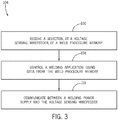
- FIG. 3 is a flow chart of an embodiment of a method 104 for using a weld procedure memory of the voltage sensing wire feeder 14.
- the voltage sensing wire feeder 14 receives a selection of a weld procedure memory.
- the weld procedure memory is selected from multiple weld procedure memories stored on the voltage sensing wire feeder 14.
- the weld procedure memory may include one or more of a wire feed speed, a power supply voltage setting, a power supply current setting, a welding process setting, a welding sequence, and so forth.
- the voltage sensing wire feeder 14 controls a welding application using data from the weld procedure memory.
- the welding power supply 12 and the voltage sensing wire feeder 14 communicate together to coordinate control of the welding application, In certain embodiments, the welding power supply 12 and the voltage sensing wire feeder 14 may communicate by providing data together with welding power over a weld cable electrically coupled between the voltage sensing wire feeder 14 and the welding power supply 12. Moreover, in some embodiments, the welding power supply 12 and the voltage sensing wire feeder 14 may communicate wirelessly, using a network interface, using a gas interface, and so forth.
- the voltage sensing wire feeder 14 may include one or more weld procedure memories. Furthermore, the voltage sensing wire feeder 14 may be configured to communicate with the welding power supply 12 to perform welding applications corresponding to the weld procedure memories without using a dedicated power/control cable (separate from the weld cable 40) coupled between the voltage sensing wire feeder 14 and the welding power supply 12. Accordingly, a number of cables extending between the welding power supply 12 and the voltage sensing wire feeder 14 may be kept to a minimal number, yet the voltage sensing wire feeder 14 may include features of a non-voltage sensing wire feeder (e.g., a constant speed wire feeder).
- a non-voltage sensing wire feeder e.g., a constant speed wire feeder
Description
- The invention relates generally to welding system with a voltage sensing wire feeder as defined in the preamble of claim 1, as for example known from
US 2012/241428 A1 . - Welding is a process that has become increasingly prevalent in various industries and applications. Such processes may be automated in certain contents, although a large number of applications continue to exist for manual welding applications. In both cases, such welding applications rely on a variety of types of equipment to ensure that the supply of welding consumables (e.g.. wire, shielding gas, etc.) is provided to the weld in an appropriate amount at the desired time. For example, metal inert gas (MIG) welding typically relies on a wire feeder to enable a welding wire to reach a welding torch. The wire is continuously fed during welding to provide filler metal. A power source ensures that arc heating is available to melt the filler metal and the underlying base metal.
- Voltage sensing wire feeders are a type of wire feeder powered using welding power provided from a welding power source, thereby obviating the use of a separate cable to power the voltage sensing wire feeder. Thus, the number of cables extending between the voltage sensing wire feeder and the welding power supply may be less than systems that use a wire feeder that is not a voltage sensing wire feeder. In a system having a wire feeder that is not voltage sensing, the cable powering the wire feeder may include multiple isolated conductive lines to carry data between the wire feeder and the welding power supply. Furthermore, a non-voltage sensing wire feeder (e.g.. constant speed wire feeder) may include processes and/or features that operate based on communication between the wire feeder and the welding power supply. Accordingly, while voltage sensing wire feeders obviate the use of a separate cable between the voltage sensing wire feeder and the welding power supply, voltage sensing wire feeders may typically be unable to communicate with the welding power supply.
- One embodiment is a welding system as defined in claim 1 and a further embodiment is a method for controlling as defined in
claim 10. - These and other features, aspects, and advantages of the present invention will become better understood when the following detailed description is read with reference to the accompanying drawings in which like characters represent like parts throughout the drawings, wherein:
-
FIG. 1 is a block diagram of an embodiment of a welding system employing devices that enable communication between a welding power supply and a voltage sensing wire feeder, in accordance with aspects of the present disclosure: -
FIG. 2 is a front view of an embodiment of a user interface of a voltage sensing wire feeder, in accordance with aspects of the present disclosure: and -
FIG. 3 is a flow chart of an embodiment of a method for using a weld procedure memory of a voltage sensing wire feeder, in accordance with aspects of the present disclosure. - Turning now to the drawings,
FIG. 1 is a block diagram of an embodiment of awelding system 10 employing devices that enable communication between a welding power supply and a voltage sensing wire feeder. In the illustrated embodiment, thewelding system 10 is a metal inert gas (MIG) welding system, although the present techniques may be used on other welding systems, such as other gas metal are welding (GMAW) systems, and so forth. Thewelding system 10 powers, controls, and supplies consumables to a welding application. Thewelding system 10 includes awelding power supply 12 and a voltage sensing wire feeder 14 (e.g.. not a constant speed wire feeder). - The
welding power supply 12 receives primary power 16 (e.g, from the AC power grid, an engine/generator set, a battery, or other energy generating or storage devices, or a combination thereof), conditions the primary power, and provides an output power to one or more welding devices in accordance with demands of thesystem 10. Theprimary power 16 may be supplied from an offsite location (i.e.. the primary power may originate from the power grid). Accordingly, thewelding power supply 12 includespower conversion circuitry 18 that may include circuit elements such as transformers, rectifiers, switches, and so forth, capable of converting the AC input power to AC or DC output power as dictated by the demands of the system 10 (e.g., particular welding processes and regimes). Such circuits are generally known in the art. - In some embodiments, the
power conversion circuitry 18 may be configured to convert theprimary power 16 to both weld and auxiliary power outputs. However, in other embodiments, thepower conversion circuitry 18 may be adapted to convert primary power only to a weld power output, and a separate auxiliary converter may be provided to convert primary power to auxiliary power. Still further, in some embodiments, thewelding power supply 12 may be adapted to receive a converted auxiliary power output directly from a wall outlet. Indeed, any suitable power conversion system or mechanism may be employed by thewelding power supply 12 to generate and supply both weld and auxiliary power. - The
welding power supply 12 includescontrol circuitry 20 to control the operation of thewelding power supply 12. Thewelding power supply 12 also includes auser interface 22. Thecontrol circuitry 20 may receive input from theuser interface 22 through which a user may choose a process and input desired parameters (e.g.. voltages, currents, particular pulsed or non-pulsed welding regimes, and so forth). The user interlace 22 may receive inputs using any input device, such as via a keypad, keyboard, buttons, touch screen, voice activation system, wireless device, etc. Furthermore, thecontrol circuitry 20 may control parameters input by the user as well as any other parameters. Specifically, theuser interface 22 may include adisplay 24 for presenting, showing, or indicating, information to an operator. Thecontrol circuitry 20 may also include interface circuitry for communicating data to other devices in thesystem 10, such as the voltagesensing wire feeder 14. Thewelding power supply 12 includes atransceiver 26 for wirelessly communicating 28 with other welding devices. In the illustrated embodiments, thewelding power supply 12 may communicate with other welding devices using a wired connection, such as by using a network interface controller (NIC) 30 to communicate data via a network 32 (e.g.. the Internet). - A
gas supply 34 provides shielding gases, such as argon, helium, carbon dioxide, and so forth, depending upon the welding application. The shielding gas flows to avalve 36, which controls the flow of gas, and if desired, may be selected to allow for modulating or regulating the amount of gas supplied to a welding application. Thevalve 36 may be opened, closed, or otherwise operated by thecontrol circuitry 20 to enable, inhibit, or control gas flow through thevalve 36. For example, when thevalve 36 is closed, shielding gas may be inhibited from flowing through thevalve 36. Conversely, when thevalve 36 is opened, shielding gas may be enabled to flow through thevalve 36. In certain embodiments, thewelding system 10 may control thevalve 36 such that data is communicated from thewelding power supply 12 to the voltagesensing wire feeder 14 using data encoded within gas flow fluctuations (e.g.. via gas pulses within the flow of gas). Shielding gas exits thevalve 36 and flows through a cable or hose 38 (which in some implementations may be packaged with the welding power output) to the voltagesensing wire feeder 14 which provides the shielding gas to the welding application. As may be appreciated, certain embodiments of thewelding system 10 may not include thegas supply 34, thevalve 36, and/or thehose 38. - Welding power flows through a
cable 40 to the voltagesensing wire feeder 14. The voltagesensing wire feeder 14 uses the welding power to power the various components in the voltagesensing wire feeder 14, such as topower control circuitry 42. Thewelding power supply 12 may also communicate with the voltagesensing wire feeder 14 using thecable 40. For example, thewelding power supply 12 and or the voltagesensing wire feeder 14 may use weld cable communication (WCC) in which data is provided over the welding power such that welding power and data are provided together using a single conductor. Accordingly, thewelding power supply 12 includesWCC circuitry 39, and thewire feeder 14 includesWCC circuitry 41 to facilitate communication using WCC between thewelding power supply 12 and thewire feeder 14. Thus, using asingle cable 40. welding power may be provided from thewelding power supply 12 to the voltagesensing wire feeder 14, and thewelding power supply 12 may communicate with the voltagesensing wire feeder 14. - The
control circuitry 42 controls the operations of the voltagesensing wire feeder 14. Thecontrol circuitry 42 includes at least one controller orprocessor 43 that controls the operations of the voltagesensing wire feeder 14, and may be configured to receive and process multiple inputs regarding the performance and demands of thesystem 10. Furthermore, theprocessor 43 may include one or more microprocessors, such as one or more "general-purpose" microprocessors, one or more special-purpose microprocessors and/or ASICS, or some combination thereof. For example, theprocessor 43 may include one or more reduced instruction set (RISC) processors. - The
control circuitry 42 may include astorage device 44 and a memory device 45. The storage device 44 (e.g., nonvolatile storage) may include ROM, flash memory, a hard drive, or any other suitable optical, magnetic, or solid-state storage medium, or a combination thereof. Thestorage device 44 may store data (e.g.. data corresponding to a welding application, one or more weld procedure memories, etc.), instructions (e.g.. software or firmware to perform welding processes), and any other suitable data. As may be appreciated, data that corresponds to a welding application may include the attitude (e.g., orientation) of a welding torch, a distance between the contact tip and a workpiece, a voltage, a current, welding device settings, and so forth. - As used herein "weld procedure memory" refers to a group of settings corresponding to a selectable input. The group of settings is stored in the
storage device 44 and/or memory device 45 of the voltagesensing wire feeder 14, and may be collectively retrieved from thestorage device 44 and/or the memory device 45 upon selection of the selectable input. Moreover, "weld procedure memories" refers to more than one "weld procedure memory" or, in other words, multiple groups of settings that respectively correspond to a selectable input. For example, the voltagesensing wire feeder 14 may include a first selectable input configured to retrieve a first group of settings corresponding to the first selectable input upon selection of the first selectable input. In addition, the voltagesensing wire feeder 14 may include a second selectable input configured to retrieve a second group of settings corresponding to the second selectable input upon selection of the second selectable input. The group of settings may include a wire feed speed, a power supply voltage setting, a power supply current setting, a power supply type setting, a power supply configuration setting, a power supply model, power supply information, a system configuration setting, a gas type, a wire size, a wire feed speed, an arc control setting, a welding process setting, a welding sequence, and any other suitable welding setting, configuration, parameter, and so forth. - The memory device 45 may include a volatile memory, such as random access memory (RAM), and/or a nonvolatile memory, such as read-only memory (ROM). The memory device 45 may store a variety of information and may be used for various purposes. For example, the memory device 45 may store processor-executable instructions (e.g.. firmware or software) for the
processor 43 to execute. In addition, a variety of control regimes for various welding processes, along with associated settings and parameters may be stored in thestorage device 44 and/or memory device 45, along with code configured to provide a specific output (e.g., initiate wire feed, enable gas flow, capture welding current data, detect short circuit parameters, determine amount of spatter, etc.) during operation. - in certain embodiments, the voltage
sensing wire feeder 14 also includes atransceiver 46 for wirelessly communicating 48 with thewelding power supply 12, or another device (e.g., either directly or through a network). In certain embodiments, thetransceiver 46 may be a Bluetooth device configured to communicate wirelessly with other devices. In certain embodiments, thetransceiver 46 may be used to transmit and/or receive weld procedure memories to and/or from another device for archival, storage, and so forth. Moreover, thetransceiver 46 may be used to transmit and/or receive data logs, error codes, error information, or any other suitable data. In the illustrated embodiment, the voltagesensing wire feeder 14 may communicate with other welding devices using a wired connection, such as by using aNIC 50 to communicate data via thenetwork 32. Moreover, the voltagesensing wire feeder 14 may communicate via thenetwork 32 using a wireless connection. - The voltage
sensing wire feeder 14 includes auser interface 52. Thecontrol circuitry 42 may receive input from theuser interface 52, such as via methods and devices described in relation to theuser interface 22. Moreover, theuser interface 52 may include one or more buttons, touch screens, switches, etc. for enabling an operator to select one of the weld procedure memories. Furthermore, thecontrol circuitry 42 may display information (e.g., on a display of the user interface 52) to an operator, such as voltage, current, wire speed, wire type, and so forth. A contactor 54 (e.g., high amperage relay) is controlled by thecontrol circuitry 42 and configured to enable or inhibit welding power to flow to aweld power cable 56 for the welding application. In certain embodiments, thecontactor 54 may be an electromechanical device, while in other embodiments thecontactor 54 may be any other suitable device, such as a solid state device. The voltagesensing wire feeder 14 includes awire drive 58 that receives control signals from thecontrol circuit 42 to driverollers 60 that rotate to pull wire off aspool 62 of wire. The wire is provided to the welding application through acable 64. Likewise, the voltagesensing wire feeder 14 may provide shielding gas through acable 66. As may be appreciated, thecables coupling device 68. - A
torch 70 delivers the wire, welding power, and shielding gas for a welding application. Thetorch 70 is used to establish a welding arc between thetorch 70 and aworkpiece 74. Awork cable 76, which may be terminated with a clamp 78 (or another power connecting device), couples thewelding power supply 12 to theworkpiece 74 to complete a welding power circuit. As illustrated, avoltage sense cable 80 is coupled from the voltagesensing wire feeder 14 to theworkpiece 74 using a sense clamp 82 (or another power connecting mechanism). Accordingly, the voltagesensing wire feeder 14 is connected to thewelding power supply 12 so that it may operate even when a welding arc is not formed by thetorch 70. Specifically, the voltagesensing wire feeder 14 receives welding power from thewelding power supply 12 throughcable 40. The welding power is connected to the various components in the voltage sensing wire feeder 14 (e.g.. control circuitry 42,wire drive 58. user interface 52). A return path for the voltagesensing wire feeder 14 power is formed using thevoltage sense cable 80 with thesense clamp 82 connected to theworkpiece 74. Further, thework cable 76 with thework clamp 78 provide the final portion of the return path to thewelding power supply 12. Thus, the return path includes thecable 80. theworkpiece 74, and thecable 76. As may be appreciated, welding power may flow in either direction through the conductive path formed bycables - Generally, wire feeders are either constant speed wire feeders (e.g., wire feeders powered using a substantially non-changing DC voltage or an AC voltage provided over a dedicated power control cable, such as a 14-conductor cable with two conductors providing power and the remaining conductors providing control signals), or voltage sensing wire feeders (e.g.. wire feeders powered using welding power provided over a weld cable). A voltage sensing wire feeder may be powered by either a constant voltage (CV), a constant current (CC), an AC, or a DC welding power supply. With a voltage sensing wire feeder and CV power source, voltage is set at the power source while wire feed speed (amperage) is set at the voltage sensing wire feeder.
- As described above, typically, a voltage sensing wire feeder does not include the ability to communicate with the
welding power supply 12 because the voltage sensing wire feeder is powered using the cable 40 (except systems in which an additional cable extends between thewelding power supply 12 and the wire feeder in systems that have such an additional cable, the communication between thewelding power supply 12 and the wire feeder is often limited by the number of conductors in the additional cable. e.g.. 14 conductors in a 14-conductor cable). However, as described herein, the voltagesensing wire feeder 14 may communicate with thewelding power supply 12 in a variety of ways without using an additional cable extending between thewelding power supply 12 and the voltage sensing wire feeder 14 (and the communication may be advanced over systems that use a dedicated communication cable because the communication described herein does not limit the type or quantity of data communicated) For example, thewelding power supply 12 and the voltagesensing wire feeder 14 may communicate using WCC by providing welding power and data together over thewelding power cable 40. As another example, thewelding power supply 12 and the voltagesensing wire feeder 14 may communicate wirelessly using thetransceivers welding power supply 12 and the voltagesensing wire feeder 14 may communicate together via a connection to the network 32 (e.g.. via the Internet). Moreover, thewelding power supply 12 may communicate with the voltagesensing wire feeder 14 using a flow of gas through the gas hose 38 (e.g.. via gas pulses within the flow of gas). Each of these communication methods do not use a cable extending between thewelding power supply 12 and the voltage sensing wire feeder 14 (except thewelding power cable 40 and the hose 38). - Accordingly, typical voltage sensing wire feeders are not capable of, and do not include, weld procedure memories, at least partly because typical voltage sensing wire feeders do not have suitable means that enable communication between the
welding power supply 12 and the voltage sensing wire feeders. In contrast, the voltagesensing wire feeder 14 includes selectable weld procedure memories and facilitates communication between thewelding power supply 12 and the voltagesensing wire feeder 14 for using the weld procedure memories. For example, a weld procedure memory may include a power supply voltage setting. As such, when the weld procedure memory is selected, the voltagesensing wire feeder 14 may provide the power supply voltage setting to thewelding power supply 12. As another example, a weld procedure memory may include data corresponding to a process (e.g., flux-cored arc welding (FCAW) no shielding gas, MIG with shielding gas, FACAW with shielding gas, pulsed MIG, stick 6010, stick 7108, lift arc TIG, scratch start TIG, air carbon arc gouging (ACAG), remote lift are TIG, etc.) or sequence (e.g., pre-flow, run-in, arc strike, weld, crater, burnback, post-flow, etc.) in which thewelding power supply 12 and the voltagesensing wire feeder 14 work together. The data corresponding to the process may include one or more voltage setting, current setting, wire speed, time, and so forth. -
FIG. 2 is a front view of an embodiment of theuser interface 52 of the voltagesensing wire feeder 14. Theuser interface 52 includes apower switch 84 for powering on/off the voltagesensing wire feeder 14. Theuser interface 52 also includes aconnector 86 for coupling thevoltage sense cable 80, and aconnector 88 for coupling to a welding torch trigger connector. Moreover, theuser interface 52 includes awire speed control 90 and avoltage control 92 that enable an operator to adjust respective settings of the voltagesensing wire feeder 14. - The
user interface 52 also includesselectors selectors selectors selector 94 may enable selection of 1, 2, 3, 4, 5, 10, 20, or more weld procedure memories. In other embodiments, the user interface S2 may include individual selectors that each only select one weld procedure memory. Theuser interface 52 includesindicators 102 to indicate the status of various parameters of the voltagesensing wire feeder 14. For example, theindicators 102 may indicate a voltage mode, a current mode, a voltage, a current, and so forth. -
FIG. 3 is a flow chart of an embodiment of amethod 104 for using a weld procedure memory of the voltagesensing wire feeder 14. Atblock 106, the voltagesensing wire feeder 14 receives a selection of a weld procedure memory. The weld procedure memory is selected from multiple weld procedure memories stored on the voltagesensing wire feeder 14. The weld procedure memory may include one or more of a wire feed speed, a power supply voltage setting, a power supply current setting, a welding process setting, a welding sequence, and so forth. Atblock 108, the voltagesensing wire feeder 14 controls a welding application using data from the weld procedure memory. Moreover, atblock 110, thewelding power supply 12 and the voltagesensing wire feeder 14 communicate together to coordinate control of the welding application, In certain embodiments, thewelding power supply 12 and the voltagesensing wire feeder 14 may communicate by providing data together with welding power over a weld cable electrically coupled between the voltagesensing wire feeder 14 and thewelding power supply 12. Moreover, in some embodiments, thewelding power supply 12 and the voltagesensing wire feeder 14 may communicate wirelessly, using a network interface, using a gas interface, and so forth. - As described herein, the voltage
sensing wire feeder 14 may include one or more weld procedure memories. Furthermore, the voltagesensing wire feeder 14 may be configured to communicate with thewelding power supply 12 to perform welding applications corresponding to the weld procedure memories without using a dedicated power/control cable (separate from the weld cable 40) coupled between the voltagesensing wire feeder 14 and thewelding power supply 12. Accordingly, a number of cables extending between thewelding power supply 12 and the voltagesensing wire feeder 14 may be kept to a minimal number, yet the voltagesensing wire feeder 14 may include features of a non-voltage sensing wire feeder (e.g., a constant speed wire feeder). - While only certain features of the invention have been illustrated and described herein, many modifications and changes will occur to those skilled in the art. It is, therefore, to be understood that the appended claims are intended to cover all such modifications and changes as fall within the scope of the invention.
Claims (11)
- A welding system with a power supply (12) and a voltage sensing wire feeder (14) powered by welding power from the welding power supply (12) provided via a weld cable (40) and comprising a user interface (52) and a wire feeder control circuitry (42) configured to control operation of the wire feeder (14),
characterized in that
the wire feeder (14) further comprises a storage device (44, 45) storing a first weld procedure memory comprising a first group of settings and a second weld procedure memory comprising a second group of settings; wherein the user interface (52) is configured to receive a first selection and a second selection, wherein the first selection is configured to direct the voltage sensing wire feeder to use the first group of settings, and the second selection is configured to direct the voltage sensing wire feeder to use the second group of settings; and
the wire feeder control circuitry (42) is configured to control operation of the wire feeder (14) based on the first group of settings and to provide the welding power supply (12) with at least one of the first group of settings when the first weld procedure memory is selected, and to control operation of the wire feeder based on the second group of settings and to provide the welding power supply (12) with at least one of the second group of settings when the second weld procedure memory is selected, and wherein the settings provided to the welding power supply (12) are provided over the welding power such that the welding power and the settings are provided together using a single conductor. - The welding system of claim 1, wherein using the first group of settings comprises the voltage sensing wire feeder (14) communicating with a welding device external to the voltage sensing wire feeder.
- The welding system of claim 2, wherein using the second group of settings comprises the voltage sensing wire feeder (14) communicating with the welding device.
- The welding system of claim 2, wherein the welding device comprises a welding power supply (12).
- The welding system of claim 2, wherein the voltage sensing wire feeder is configured to communicate with the power supply (12) of the welding device over the weld cable (40) via weld cable (40) communication (WCC).
- The welding system of one of the preceding claims, wherein the control circuitry (42) is configured to receive combined welding power and data from a welding power supply (12), and to provide combined welding power and data to the welding power supply (12), wherein the combined welding power and data enables communication between the voltage sensing wire feeder (14) and the welding power supply (12) for using the first group of settings, the second group of settings, or some combination thereof.
- The welding system of one of the preceding claims, wherein the user interface (52) comprises an input device (94, 96, 98, 100) configured to receive the first selection, the second selection, or some combination thereof.
- The welding system of one of the preceding claims, wherein the first group of settings, the second group of settings, or some combination thereof, comprises a power supply voltage setting, a power supply current setting, a power supply type setting, a power supply configuration setting, a system configuration setting, an arc control setting, a welding process setting, a welding sequence, or some combination thereof.
- The welding system of one of the preceding claims, wherein using the first group of settings, the second group of settings, or some combination thereof, depends on communication between the voltage sensing wire feeder (14) and the welding power supply (12).
- A method for controlling a voltage sensing wire feeder (14), comprising the steps of receiving a selection, at the voltage sensing wire feeder (14), of a group of settings from a plurality of groups of settings stored in a storage device (44, 45) of the voltage sensing wire feeder;
controlling operation of the voltage sensing wire feeder (14) using the selected group of settings; and providing the settings together with welding power to a welding power supply (12) using a single conductor . - The method of claim 10, wherein the group of settings comprises a power supply voltage setting, a power supply current setting, a power supply type setting, a power supply configuration setting, a system configuration setting, an arc control setting, a welding process setting, a welding sequence, or some combination thereof
Applications Claiming Priority (2)
| Application Number | Priority Date | Filing Date | Title |
|---|---|---|---|
| US13/799,367 US10076809B2 (en) | 2013-03-13 | 2013-03-13 | Voltage sensing wire feeder with weld procedure memories |
| PCT/US2014/017503 WO2014163826A1 (en) | 2013-03-13 | 2014-02-20 | Voltage sensing wire feeder with weld procedure memories |
Publications (2)
| Publication Number | Publication Date |
|---|---|
| EP2969350A1 EP2969350A1 (en) | 2016-01-20 |
| EP2969350B1 true EP2969350B1 (en) | 2019-02-06 |
Family
ID=50272736
Family Applications (1)
| Application Number | Title | Priority Date | Filing Date |
|---|---|---|---|
| EP14709820.6A Active EP2969350B1 (en) | 2013-03-13 | 2014-02-20 | Voltage sensing wire feeder with weld procedure memories |
Country Status (10)
| Country | Link |
|---|---|
| US (2) | US10076809B2 (en) |
| EP (1) | EP2969350B1 (en) |
| JP (1) | JP2016515940A (en) |
| KR (1) | KR102152482B1 (en) |
| CN (2) | CN105073323B (en) |
| AU (1) | AU2014249976B2 (en) |
| BR (1) | BR112015015442A2 (en) |
| CA (1) | CA2891518C (en) |
| MX (1) | MX347268B (en) |
| WO (1) | WO2014163826A1 (en) |
Families Citing this family (19)
| Publication number | Priority date | Publication date | Assignee | Title |
|---|---|---|---|---|
| US11198190B2 (en) * | 2014-12-18 | 2021-12-14 | Illinois Tool Works Inc. | Systems and methods for duplex communications over a welding cable |
| US10449614B2 (en) | 2014-12-18 | 2019-10-22 | Illinois Tool Works Inc. | Systems and methods for solid state sensor measurements of welding cables |
| US10828713B2 (en) | 2014-12-18 | 2020-11-10 | Illinois Tool Works Inc. | Systems and methods for adaptively controlling physical layers for weld cable communications |
| US10682722B2 (en) | 2014-12-18 | 2020-06-16 | Illinois Tool Works Inc. | Systems and methods for measuring characteristics of a welding cable with a low power transceiver |
| US9943925B2 (en) * | 2014-12-18 | 2018-04-17 | Illinois Tool Works Inc. | Systems and methods for adaptively controlling weld cable communications |
| US10906119B2 (en) | 2014-12-18 | 2021-02-02 | Illinois Tool Works Inc. | Systems and methods for communication via a welding cable |
| US9969024B2 (en) * | 2014-12-18 | 2018-05-15 | Illinois Tool Works Inc. | Systems and methods for measuring characteristics of a welding cable |
| GB2541721A (en) * | 2015-08-28 | 2017-03-01 | Linde Ag | A sensor module for a fabrication tool |
| US10532419B2 (en) * | 2015-10-29 | 2020-01-14 | Lincoln Global, Inc. | System and method of communicating in a welding system over welding power cables |
| US10773331B2 (en) | 2016-08-16 | 2020-09-15 | Illinois Tool Works Inc. | Welding power supplies, wire feeders, and systems to compensate a weld voltage via communications over a weld circuit |
| US10603735B2 (en) | 2016-08-16 | 2020-03-31 | Illinois Tool Works Inc. | Welding power supplies, wire feeders, and systems to compensate a weld voltage via communications over a weld circuit |
| US11027355B2 (en) * | 2017-03-09 | 2021-06-08 | Illinois Tool Works | Welding power supplies, wire feeders, and systems to measure a weld circuit resistance via communications over the weld circuit |
| US11660695B2 (en) | 2017-03-09 | 2023-05-30 | Illinois Tool Works Inc. | Welding power supplies, wire feeders, and systems to measure a weld cable voltage drop |
| US11204394B2 (en) * | 2017-09-20 | 2021-12-21 | Esab Ab | External connector and sensor unit for welding equipment |
| US20190351501A1 (en) * | 2018-05-21 | 2019-11-21 | Illinois Tool Works Inc. | Welding power supplies and user interfaces for welding power supplies |
| USD914071S1 (en) | 2018-11-02 | 2021-03-23 | Esab Ab | Welding device enclosure |
| CN114650894A (en) * | 2019-11-18 | 2022-06-21 | 松下知识产权经营株式会社 | Welding machine |
| US11361656B2 (en) | 2020-08-28 | 2022-06-14 | Greenlee Tools, Inc. | Wireless control in a cable feeder and puller system |
| CN116034523A (en) | 2020-08-28 | 2023-04-28 | 格林利工具公司 | Wireless control in a cable feeder and retractor system |
Family Cites Families (89)
| Publication number | Priority date | Publication date | Assignee | Title |
|---|---|---|---|---|
| US2043331A (en) | 1934-11-26 | 1936-06-09 | J D Adams Mfg Company | Control for welding apparatus |
| US2175891A (en) | 1935-09-26 | 1939-10-10 | Westinghouse Electric & Mfg Co | Control system |
| US2526597A (en) | 1945-08-10 | 1950-10-17 | Winslow Paul Howard | Current control system |
| US2617913A (en) | 1950-09-30 | 1952-11-11 | Harnischfeger Corp | Low open circuit voltage alternating current welding circuit |
| US2642515A (en) | 1950-10-30 | 1953-06-16 | Earle W Bagg | Remote control for arc welding |
| US3496328A (en) | 1967-11-24 | 1970-02-17 | Delford A Moerke | Welding gun |
| US4051344A (en) | 1975-04-28 | 1977-09-27 | Robbins Dennis R | Remote control for an arc welding machine |
| US3992565A (en) | 1975-07-07 | 1976-11-16 | Belden Corporation | Composite welding cable having gas ducts and switch wires therein |
| NO136138C (en) | 1975-09-26 | 1980-12-02 | Jon Erlend Gloemmen | DEVICE FOR REMOTE CONTROL OF NETWORK DRIVE AND AC AC WELDING MACHINES |
| US4079231A (en) | 1976-03-30 | 1978-03-14 | Union Carbide Corporation | Touchwork system for a MIG arc welding apparatus |
| US4147919A (en) | 1977-01-24 | 1979-04-03 | Matasovic John L | Remote control portable wirefeed arc welding system |
| US4247752A (en) | 1978-03-31 | 1981-01-27 | Westinghouse Electric Corp. | Constant current arc welder |
| US4216367A (en) | 1978-04-18 | 1980-08-05 | Miller Electric Manufacturing Company | Wireless remote control for electric welder |
| US4216368A (en) | 1978-11-27 | 1980-08-05 | Delay Calvin J | Remote control device for arc welding |
| US4227066A (en) | 1979-02-12 | 1980-10-07 | Bulwidas Jr John J | Hand-operated remote control unit and mounting structure for an arc welding machine |
| US4467174A (en) | 1981-02-19 | 1984-08-21 | Gilliland Malcolm T | Remote control of open circuit voltage in a welding power supply |
| US4410789A (en) | 1981-09-09 | 1983-10-18 | Story Alan R | Remote control for welding machine amperage |
| US4521672A (en) | 1981-10-27 | 1985-06-04 | Miller Electric Manufacturing Company | Electronic welding apparatus |
| US4450340A (en) | 1982-12-10 | 1984-05-22 | Miller Electric Manufacturing Company | Arc welder power supply with fail-safe voltage reducing circuit |
| US4561059A (en) | 1983-02-24 | 1985-12-24 | Beckworth Davis International, Inc. | Microprocessor controlled welding apparatus |
| US4641292A (en) | 1983-06-20 | 1987-02-03 | George Tunnell | Voice controlled welding system |
| US4608482A (en) | 1983-09-23 | 1986-08-26 | Ron Cox | Control for welding system |
| US4584685A (en) | 1983-12-22 | 1986-04-22 | General Electric Company | Method for improving message reception from multiple sources |
| US4508954A (en) | 1984-05-18 | 1985-04-02 | Oxo Welding Equipment Co., Inc. | Portable arc voltage wirefeed welding system |
| US4531045A (en) | 1984-06-27 | 1985-07-23 | Hobart Brothers Company | Trigger hold circuit for welding power supply |
| JPS61137675A (en) | 1984-12-10 | 1986-06-25 | Nippon Steel Corp | Automatic welder |
| IT1204121B (en) | 1986-02-27 | 1989-03-01 | Cebora Spa | WELDING TORCH OR PLASMA CUTTING WITH NON-TRANSFERRED ARC |
| US4769754A (en) | 1987-07-27 | 1988-09-06 | Miller Electric Mfg., Co. | Stabilized welding power source including a series-resonant current-regulated converter using a transformer having an air-gapped core |
| JPH07115183B2 (en) | 1988-06-29 | 1995-12-13 | 三菱電機株式会社 | Load voltage detection system, pulse arc welding apparatus, pulse laser apparatus and surface treatment apparatus using the detection system |
| US4918517A (en) | 1989-01-26 | 1990-04-17 | Westinghouse Electric Corp. | System and process for video monitoring a welding operation |
| US4973821A (en) | 1989-04-03 | 1990-11-27 | Donald L. Martin | Control unit for welding apparatus having offset and tracking control features |
| US5063282A (en) | 1989-06-30 | 1991-11-05 | Gilliland Malcolm T | Apparatus and method for optimizing a welding operation |
| DE3925100A1 (en) | 1989-07-28 | 1991-01-31 | Trw Nelson Bolzenschweiss Tech | ELECTRIC BOLT WELDING MACHINE |
| JPH0616946B2 (en) | 1990-10-26 | 1994-03-09 | デンヨー株式会社 | Method and apparatus for remote control of engine welder |
| JPH0616948B2 (en) | 1990-10-26 | 1994-03-09 | デンヨー株式会社 | Remote control method for engine welder |
| JP3155786B2 (en) | 1991-10-11 | 2001-04-16 | 日立ビアメカニクス株式会社 | Semi-automatic arc welding machine |
| FI91497B (en) | 1992-06-15 | 1994-03-31 | Kemppi Oy | Apparatus and method for adjusting the power supply and / or auxiliary equipment of a welding machine by radio frequency signals |
| US5406050A (en) | 1992-10-08 | 1995-04-11 | Advanced Fusion Technologies, Inc. | Multiple operator welding apparatus |
| US5276305A (en) | 1992-12-09 | 1994-01-04 | Industrial Technology Research Institute | Remote control setting device for electric welding machines |
| US5376894A (en) | 1992-12-31 | 1994-12-27 | Pacific Communication Sciences, Inc. | Phase estimation and synchronization using a PSK demodulator |
| KR0124988B1 (en) | 1994-09-28 | 1997-12-26 | 김준성 | Velding line course revision method of automatic welding machine |
| JP3114579B2 (en) | 1995-08-30 | 2000-12-04 | 松下電器産業株式会社 | Industrial robot and its control device |
| US6225596B1 (en) | 1996-03-20 | 2001-05-01 | Century Mfg. Co. | Portable welding unit |
| DE19646747C1 (en) | 1996-11-01 | 1998-08-13 | Nanotron Ges Fuer Mikrotechnik | Method for the wireless transmission of a message imprinted on a signal |
| US6091048A (en) * | 1997-05-16 | 2000-07-18 | Illinois Tool Works Inc. | Welding machine with automatic parameter setting |
| US6458157B1 (en) | 1997-08-04 | 2002-10-01 | Suaning Gregg Joergen | Retinal stimulator |
| US5982253A (en) | 1997-08-27 | 1999-11-09 | Nartron Corporation | In-line module for attenuating electrical noise with male and female blade terminals |
| GB9800405D0 (en) | 1998-01-10 | 1998-03-04 | Reed Edward John | Welding method and apparatus |
| US6040555A (en) | 1998-02-20 | 2000-03-21 | Illinois Tool Works Inc. | Remote control for welders and method therefor |
| US6066832A (en) * | 1998-04-23 | 2000-05-23 | Illinois Tool Works Inc. | Welding arc voltage sense lead |
| US6166506A (en) | 1998-06-19 | 2000-12-26 | Tregaskiss, Ltd. | Wireless safety clutch |
| US6156999A (en) | 1998-12-28 | 2000-12-05 | Plasma-Laser Technologies Ltd. | Method and device for welding arc ignition for arc welding apparatus |
| AT406942B (en) | 1999-01-15 | 2000-10-25 | Fronius Schweissmasch | REMOTE CONTROL UNIT FOR A WELDING MACHINE OR A POWER SOURCE |
| US6114657A (en) | 1999-04-01 | 2000-09-05 | Illinois Tool Works Inc. | Method and apparatus for welding with a trigger hold |
| US6103994A (en) * | 1999-04-12 | 2000-08-15 | Illinois Tool Works | Welding device with remote device detection |
| US6335513B1 (en) | 2000-07-31 | 2002-01-01 | Weld-Aid Products, Inc. | Apparatus and method for electromagnetic removal of spatter from a nozzle of an arc welding torch |
| US6479795B1 (en) | 2000-10-11 | 2002-11-12 | Illinois Tool Works Inc. | Portable welding wire feeder and housing |
| US6624388B1 (en) | 2001-01-25 | 2003-09-23 | The Lincoln Electric Company | System and method providing distributed welding architecture |
| US6627849B2 (en) | 2001-05-11 | 2003-09-30 | Illinois Tool Works Inc. | Automatic detection of robot type |
| US6479791B1 (en) | 2001-05-11 | 2002-11-12 | Illinois Tool Works Inc. | Dynamic voltage sensing with failure indication |
| JP2003088957A (en) | 2001-09-18 | 2003-03-25 | Daihen Corp | Consumable electrode arc welding equipment |
| JP2003154455A (en) | 2001-11-21 | 2003-05-27 | Daihen Corp | Consumable electrode type arc welding equipment |
| JP4739621B2 (en) | 2001-12-25 | 2011-08-03 | 株式会社ダイヘン | Consumable electrode arc welding equipment |
| JP4777589B2 (en) | 2002-02-19 | 2011-09-21 | 株式会社ダイヘン | Non-consumable electrode arc welding equipment |
| CN101883072A (en) | 2002-04-12 | 2010-11-10 | 松下电器产业株式会社 | Multicarrier sending and receiving device and method, base station, communication terminal |
| US6909285B2 (en) | 2002-09-11 | 2005-06-21 | Visteon Global Technologies, Inc. | Method for detecting failure of a relay |
| JP4162964B2 (en) | 2002-10-03 | 2008-10-08 | 株式会社日立ハウステック | Air pump with channel switching function with both outlet and outlet |
| US6818860B1 (en) | 2003-06-26 | 2004-11-16 | Lincoln Global, Inc. | Portable welder with integral battery charger |
| US7205503B2 (en) | 2003-07-24 | 2007-04-17 | Illinois Tool Works Inc. | Remotely controlled welding machine |
| US6906285B2 (en) | 2003-10-24 | 2005-06-14 | Lincoln Global, Inc. | Remote wire feeder |
| US7294808B2 (en) | 2004-03-15 | 2007-11-13 | Lincoln Global, Inc. | Remote wire feeder |
| US7180029B2 (en) | 2004-04-16 | 2007-02-20 | Illinois Tool Works Inc. | Method and system for a remote wire feeder where standby power and system control are provided via weld cables |
| US8592724B2 (en) | 2004-04-16 | 2013-11-26 | Illinois Tool Works Inc. | Remote wire feeder using binary phase shift keying to modulate communications of command/control signals to be transmitted over a weld cable |
| US9012807B2 (en) * | 2004-04-16 | 2015-04-21 | Illinois Tool Works Inc. | Remote wire feeder using binary phase shift keying to modulate communications of command/control signals to be transmitted over a weld cable |
| US7381922B2 (en) | 2004-10-27 | 2008-06-03 | Illinois Tool Works Inc. | Method and apparatus for remotely controlling a welding system |
| US7247814B2 (en) | 2005-03-23 | 2007-07-24 | Illinois Tool Works Inc. | System and method for data communications over a gas hose in a welding-type application |
| US8431862B2 (en) * | 2005-08-25 | 2013-04-30 | Lincoln Global, Inc. | Torch for electric arc welding system |
| US9579743B2 (en) * | 2006-07-12 | 2017-02-28 | Lincoln Global, Inc. | Coaxial welding cable assembly |
| US8592722B2 (en) * | 2008-11-03 | 2013-11-26 | Illinois Tool Works Inc. | Weld parameter interface |
| EP2459991B1 (en) | 2009-07-29 | 2019-09-11 | American Science & Engineering, Inc. | Top-down x-ray inspection trailer |
| US8330077B2 (en) | 2009-09-03 | 2012-12-11 | Illinois Tool Works Inc. | Remote welding system and method |
| US8957344B2 (en) | 2009-09-30 | 2015-02-17 | Illinois Tool Works Inc. | Welding system with power line communication |
| US20110240620A1 (en) | 2010-04-05 | 2011-10-06 | Illinois Tool Works Inc. | Welding system and method utilizing internal ethernet communications |
| US9061367B2 (en) * | 2010-04-13 | 2015-06-23 | Illinois Tool Works Inc. | Weld electrical and gas connector with sealed gas flow |
| US20120097644A1 (en) | 2010-10-26 | 2012-04-26 | Illinois Tool Works Inc. | Modular data over power converter for welding power supply |
| US10058948B2 (en) * | 2010-12-29 | 2018-08-28 | Illinois Tool Works Inc. | Weld cell system with communication |
| US11110538B2 (en) * | 2011-03-25 | 2021-09-07 | Illinois Tool Works Inc. | Systems and methods for adjusting multiple settings of a welding power supply |
| US10259067B2 (en) * | 2012-06-04 | 2019-04-16 | Illinois Tool Works Inc. | Remote polarity detection and control for welding process |
| US20140061169A1 (en) * | 2012-08-29 | 2014-03-06 | Illinois Tool Works Inc. | User interface for welding equipment and systems |
-
2013
- 2013-03-13 US US13/799,367 patent/US10076809B2/en active Active
-
2014
- 2014-02-20 JP JP2016500319A patent/JP2016515940A/en active Pending
- 2014-02-20 BR BR112015015442A patent/BR112015015442A2/en not_active IP Right Cessation
- 2014-02-20 CA CA2891518A patent/CA2891518C/en active Active
- 2014-02-20 KR KR1020157015523A patent/KR102152482B1/en active IP Right Grant
- 2014-02-20 WO PCT/US2014/017503 patent/WO2014163826A1/en active Application Filing
- 2014-02-20 AU AU2014249976A patent/AU2014249976B2/en not_active Ceased
- 2014-02-20 EP EP14709820.6A patent/EP2969350B1/en active Active
- 2014-02-20 CN CN201480008874.XA patent/CN105073323B/en not_active Expired - Fee Related
- 2014-02-20 CN CN201711091336.3A patent/CN107813030B/en not_active Expired - Fee Related
- 2014-02-20 MX MX2015006052A patent/MX347268B/en active IP Right Grant
-
2018
- 2018-08-14 US US16/103,541 patent/US11007610B2/en active Active
Non-Patent Citations (1)
| Title |
|---|
| None * |
Also Published As
| Publication number | Publication date |
|---|---|
| US20140263256A1 (en) | 2014-09-18 |
| BR112015015442A2 (en) | 2017-07-11 |
| AU2014249976A1 (en) | 2015-06-04 |
| MX347268B (en) | 2017-04-20 |
| MX2015006052A (en) | 2015-10-26 |
| CN107813030B (en) | 2020-04-14 |
| US20180369968A1 (en) | 2018-12-27 |
| KR20150123782A (en) | 2015-11-04 |
| AU2014249976B2 (en) | 2016-12-22 |
| JP2016515940A (en) | 2016-06-02 |
| KR102152482B1 (en) | 2020-09-04 |
| CN107813030A (en) | 2018-03-20 |
| CA2891518C (en) | 2020-08-11 |
| WO2014163826A1 (en) | 2014-10-09 |
| CN105073323A (en) | 2015-11-18 |
| CA2891518A1 (en) | 2014-10-09 |
| US11007610B2 (en) | 2021-05-18 |
| CN105073323B (en) | 2017-12-01 |
| EP2969350A1 (en) | 2016-01-20 |
| US10076809B2 (en) | 2018-09-18 |
Similar Documents
| Publication | Publication Date | Title |
|---|---|---|
| US11007610B2 (en) | Voltage sensing wire feeder with weld procedure memories | |
| US20210205912A1 (en) | Systems and methods for selecting a welding process | |
| US20110220616A1 (en) | Welding device with integral user interface | |
| US9643276B2 (en) | Welding wire retraction system and method | |
| EP4039397A1 (en) | Preheating power supply to control weld current in a preheating system | |
| AU2013288912B2 (en) | Methods and systems for feeding filler material to a welding operation | |
| CN112533722B (en) | Welding power supply and user interface for a welding power supply | |
| US20190366469A1 (en) | Welding power supplies and user interfaces to control output polarity for welding power supplies |
Legal Events
| Date | Code | Title | Description |
|---|---|---|---|
| PUAI | Public reference made under article 153(3) epc to a published international application that has entered the european phase |
Free format text: ORIGINAL CODE: 0009012 |
|
| 17P | Request for examination filed |
Effective date: 20150527 |
|
| AK | Designated contracting states |
Kind code of ref document: A1 Designated state(s): AL AT BE BG CH CY CZ DE DK EE ES FI FR GB GR HR HU IE IS IT LI LT LU LV MC MK MT NL NO PL PT RO RS SE SI SK SM TR |
|
| AX | Request for extension of the european patent |
Extension state: BA ME |
|
| DAX | Request for extension of the european patent (deleted) | ||
| STAA | Information on the status of an ep patent application or granted ep patent |
Free format text: STATUS: EXAMINATION IS IN PROGRESS |
|
| 17Q | First examination report despatched |
Effective date: 20171205 |
|
| GRAP | Despatch of communication of intention to grant a patent |
Free format text: ORIGINAL CODE: EPIDOSNIGR1 |
|
| STAA | Information on the status of an ep patent application or granted ep patent |
Free format text: STATUS: GRANT OF PATENT IS INTENDED |
|
| INTG | Intention to grant announced |
Effective date: 20181002 |
|
| GRAS | Grant fee paid |
Free format text: ORIGINAL CODE: EPIDOSNIGR3 |
|
| GRAA | (expected) grant |
Free format text: ORIGINAL CODE: 0009210 |
|
| STAA | Information on the status of an ep patent application or granted ep patent |
Free format text: STATUS: THE PATENT HAS BEEN GRANTED |
|
| AK | Designated contracting states |
Kind code of ref document: B1 Designated state(s): AL AT BE BG CH CY CZ DE DK EE ES FI FR GB GR HR HU IE IS IT LI LT LU LV MC MK MT NL NO PL PT RO RS SE SI SK SM TR |
|
| REG | Reference to a national code |
Ref country code: GB Ref legal event code: FG4D |
|
| REG | Reference to a national code |
Ref country code: CH Ref legal event code: EP Ref country code: AT Ref legal event code: REF Ref document number: 1094557 Country of ref document: AT Kind code of ref document: T Effective date: 20190215 |
|
| REG | Reference to a national code |
Ref country code: IE Ref legal event code: FG4D |
|
| REG | Reference to a national code |
Ref country code: DE Ref legal event code: R096 Ref document number: 602014040712 Country of ref document: DE |
|
| REG | Reference to a national code |
Ref country code: NL Ref legal event code: MP Effective date: 20190206 |
|
| REG | Reference to a national code |
Ref country code: LT Ref legal event code: MG4D |
|
| PG25 | Lapsed in a contracting state [announced via postgrant information from national office to epo] |
Ref country code: LT Free format text: LAPSE BECAUSE OF FAILURE TO SUBMIT A TRANSLATION OF THE DESCRIPTION OR TO PAY THE FEE WITHIN THE PRESCRIBED TIME-LIMIT Effective date: 20190206 Ref country code: NL Free format text: LAPSE BECAUSE OF FAILURE TO SUBMIT A TRANSLATION OF THE DESCRIPTION OR TO PAY THE FEE WITHIN THE PRESCRIBED TIME-LIMIT Effective date: 20190206 Ref country code: FI Free format text: LAPSE BECAUSE OF FAILURE TO SUBMIT A TRANSLATION OF THE DESCRIPTION OR TO PAY THE FEE WITHIN THE PRESCRIBED TIME-LIMIT Effective date: 20190206 Ref country code: SE Free format text: LAPSE BECAUSE OF FAILURE TO SUBMIT A TRANSLATION OF THE DESCRIPTION OR TO PAY THE FEE WITHIN THE PRESCRIBED TIME-LIMIT Effective date: 20190206 Ref country code: NO Free format text: LAPSE BECAUSE OF FAILURE TO SUBMIT A TRANSLATION OF THE DESCRIPTION OR TO PAY THE FEE WITHIN THE PRESCRIBED TIME-LIMIT Effective date: 20190506 Ref country code: PT Free format text: LAPSE BECAUSE OF FAILURE TO SUBMIT A TRANSLATION OF THE DESCRIPTION OR TO PAY THE FEE WITHIN THE PRESCRIBED TIME-LIMIT Effective date: 20190606 |
|
| REG | Reference to a national code |
Ref country code: AT Ref legal event code: MK05 Ref document number: 1094557 Country of ref document: AT Kind code of ref document: T Effective date: 20190206 |
|
| PG25 | Lapsed in a contracting state [announced via postgrant information from national office to epo] |
Ref country code: BG Free format text: LAPSE BECAUSE OF FAILURE TO SUBMIT A TRANSLATION OF THE DESCRIPTION OR TO PAY THE FEE WITHIN THE PRESCRIBED TIME-LIMIT Effective date: 20190506 Ref country code: RS Free format text: LAPSE BECAUSE OF FAILURE TO SUBMIT A TRANSLATION OF THE DESCRIPTION OR TO PAY THE FEE WITHIN THE PRESCRIBED TIME-LIMIT Effective date: 20190206 Ref country code: LV Free format text: LAPSE BECAUSE OF FAILURE TO SUBMIT A TRANSLATION OF THE DESCRIPTION OR TO PAY THE FEE WITHIN THE PRESCRIBED TIME-LIMIT Effective date: 20190206 Ref country code: IS Free format text: LAPSE BECAUSE OF FAILURE TO SUBMIT A TRANSLATION OF THE DESCRIPTION OR TO PAY THE FEE WITHIN THE PRESCRIBED TIME-LIMIT Effective date: 20190606 Ref country code: HR Free format text: LAPSE BECAUSE OF FAILURE TO SUBMIT A TRANSLATION OF THE DESCRIPTION OR TO PAY THE FEE WITHIN THE PRESCRIBED TIME-LIMIT Effective date: 20190206 Ref country code: GR Free format text: LAPSE BECAUSE OF FAILURE TO SUBMIT A TRANSLATION OF THE DESCRIPTION OR TO PAY THE FEE WITHIN THE PRESCRIBED TIME-LIMIT Effective date: 20190507 |
|
| REG | Reference to a national code |
Ref country code: CH Ref legal event code: PL |
|
| PG25 | Lapsed in a contracting state [announced via postgrant information from national office to epo] |
Ref country code: ES Free format text: LAPSE BECAUSE OF FAILURE TO SUBMIT A TRANSLATION OF THE DESCRIPTION OR TO PAY THE FEE WITHIN THE PRESCRIBED TIME-LIMIT Effective date: 20190206 Ref country code: AL Free format text: LAPSE BECAUSE OF FAILURE TO SUBMIT A TRANSLATION OF THE DESCRIPTION OR TO PAY THE FEE WITHIN THE PRESCRIBED TIME-LIMIT Effective date: 20190206 Ref country code: LU Free format text: LAPSE BECAUSE OF NON-PAYMENT OF DUE FEES Effective date: 20190220 Ref country code: DK Free format text: LAPSE BECAUSE OF FAILURE TO SUBMIT A TRANSLATION OF THE DESCRIPTION OR TO PAY THE FEE WITHIN THE PRESCRIBED TIME-LIMIT Effective date: 20190206 Ref country code: SK Free format text: LAPSE BECAUSE OF FAILURE TO SUBMIT A TRANSLATION OF THE DESCRIPTION OR TO PAY THE FEE WITHIN THE PRESCRIBED TIME-LIMIT Effective date: 20190206 Ref country code: EE Free format text: LAPSE BECAUSE OF FAILURE TO SUBMIT A TRANSLATION OF THE DESCRIPTION OR TO PAY THE FEE WITHIN THE PRESCRIBED TIME-LIMIT Effective date: 20190206 Ref country code: RO Free format text: LAPSE BECAUSE OF FAILURE TO SUBMIT A TRANSLATION OF THE DESCRIPTION OR TO PAY THE FEE WITHIN THE PRESCRIBED TIME-LIMIT Effective date: 20190206 Ref country code: CZ Free format text: LAPSE BECAUSE OF FAILURE TO SUBMIT A TRANSLATION OF THE DESCRIPTION OR TO PAY THE FEE WITHIN THE PRESCRIBED TIME-LIMIT Effective date: 20190206 |
|
| REG | Reference to a national code |
Ref country code: DE Ref legal event code: R097 Ref document number: 602014040712 Country of ref document: DE |
|
| REG | Reference to a national code |
Ref country code: BE Ref legal event code: MM Effective date: 20190228 |
|
| REG | Reference to a national code |
Ref country code: IE Ref legal event code: MM4A |
|
| PG25 | Lapsed in a contracting state [announced via postgrant information from national office to epo] |
Ref country code: PL Free format text: LAPSE BECAUSE OF FAILURE TO SUBMIT A TRANSLATION OF THE DESCRIPTION OR TO PAY THE FEE WITHIN THE PRESCRIBED TIME-LIMIT Effective date: 20190206 Ref country code: SM Free format text: LAPSE BECAUSE OF FAILURE TO SUBMIT A TRANSLATION OF THE DESCRIPTION OR TO PAY THE FEE WITHIN THE PRESCRIBED TIME-LIMIT Effective date: 20190206 |
|
| PLBE | No opposition filed within time limit |
Free format text: ORIGINAL CODE: 0009261 |
|
| STAA | Information on the status of an ep patent application or granted ep patent |
Free format text: STATUS: NO OPPOSITION FILED WITHIN TIME LIMIT |
|
| PG25 | Lapsed in a contracting state [announced via postgrant information from national office to epo] |
Ref country code: MC Free format text: LAPSE BECAUSE OF FAILURE TO SUBMIT A TRANSLATION OF THE DESCRIPTION OR TO PAY THE FEE WITHIN THE PRESCRIBED TIME-LIMIT Effective date: 20190206 Ref country code: LI Free format text: LAPSE BECAUSE OF NON-PAYMENT OF DUE FEES Effective date: 20190228 Ref country code: AT Free format text: LAPSE BECAUSE OF FAILURE TO SUBMIT A TRANSLATION OF THE DESCRIPTION OR TO PAY THE FEE WITHIN THE PRESCRIBED TIME-LIMIT Effective date: 20190206 Ref country code: CH Free format text: LAPSE BECAUSE OF NON-PAYMENT OF DUE FEES Effective date: 20190228 |
|
| 26N | No opposition filed |
Effective date: 20191107 |
|
| GBPC | Gb: european patent ceased through non-payment of renewal fee |
Effective date: 20190506 |
|
| PG25 | Lapsed in a contracting state [announced via postgrant information from national office to epo] |
Ref country code: IE Free format text: LAPSE BECAUSE OF NON-PAYMENT OF DUE FEES Effective date: 20190220 |
|
| PG25 | Lapsed in a contracting state [announced via postgrant information from national office to epo] |
Ref country code: BE Free format text: LAPSE BECAUSE OF NON-PAYMENT OF DUE FEES Effective date: 20190228 Ref country code: SI Free format text: LAPSE BECAUSE OF FAILURE TO SUBMIT A TRANSLATION OF THE DESCRIPTION OR TO PAY THE FEE WITHIN THE PRESCRIBED TIME-LIMIT Effective date: 20190206 |
|
| PG25 | Lapsed in a contracting state [announced via postgrant information from national office to epo] |
Ref country code: TR Free format text: LAPSE BECAUSE OF FAILURE TO SUBMIT A TRANSLATION OF THE DESCRIPTION OR TO PAY THE FEE WITHIN THE PRESCRIBED TIME-LIMIT Effective date: 20190206 |
|
| PG25 | Lapsed in a contracting state [announced via postgrant information from national office to epo] |
Ref country code: GB Free format text: LAPSE BECAUSE OF NON-PAYMENT OF DUE FEES Effective date: 20190506 |
|
| PG25 | Lapsed in a contracting state [announced via postgrant information from national office to epo] |
Ref country code: MT Free format text: LAPSE BECAUSE OF NON-PAYMENT OF DUE FEES Effective date: 20190220 |
|
| PGFP | Annual fee paid to national office [announced via postgrant information from national office to epo] |
Ref country code: FR Payment date: 20200225 Year of fee payment: 7 |
|
| PG25 | Lapsed in a contracting state [announced via postgrant information from national office to epo] |
Ref country code: CY Free format text: LAPSE BECAUSE OF FAILURE TO SUBMIT A TRANSLATION OF THE DESCRIPTION OR TO PAY THE FEE WITHIN THE PRESCRIBED TIME-LIMIT Effective date: 20190206 |
|
| PG25 | Lapsed in a contracting state [announced via postgrant information from national office to epo] |
Ref country code: HU Free format text: LAPSE BECAUSE OF FAILURE TO SUBMIT A TRANSLATION OF THE DESCRIPTION OR TO PAY THE FEE WITHIN THE PRESCRIBED TIME-LIMIT; INVALID AB INITIO Effective date: 20140220 |
|
| PG25 | Lapsed in a contracting state [announced via postgrant information from national office to epo] |
Ref country code: FR Free format text: LAPSE BECAUSE OF NON-PAYMENT OF DUE FEES Effective date: 20210228 |
|
| PG25 | Lapsed in a contracting state [announced via postgrant information from national office to epo] |
Ref country code: MK Free format text: LAPSE BECAUSE OF FAILURE TO SUBMIT A TRANSLATION OF THE DESCRIPTION OR TO PAY THE FEE WITHIN THE PRESCRIBED TIME-LIMIT Effective date: 20190206 |
|
| PGFP | Annual fee paid to national office [announced via postgrant information from national office to epo] |
Ref country code: IT Payment date: 20230221 Year of fee payment: 10 Ref country code: DE Payment date: 20230223 Year of fee payment: 10 |
|
| P01 | Opt-out of the competence of the unified patent court (upc) registered |
Effective date: 20230606 |