EP2969293B1 - Herstellungsverfahren für eine anströmkantenummantelung - Google Patents
Herstellungsverfahren für eine anströmkantenummantelung Download PDFInfo
- Publication number
- EP2969293B1 EP2969293B1 EP13878459.0A EP13878459A EP2969293B1 EP 2969293 B1 EP2969293 B1 EP 2969293B1 EP 13878459 A EP13878459 A EP 13878459A EP 2969293 B1 EP2969293 B1 EP 2969293B1
- Authority
- EP
- European Patent Office
- Prior art keywords
- sheath
- leading edge
- plate
- fan blade
- protective sheath
- Prior art date
- Legal status (The legal status is an assumption and is not a legal conclusion. Google has not performed a legal analysis and makes no representation as to the accuracy of the status listed.)
- Active
Links
Images
Classifications
-
- B—PERFORMING OPERATIONS; TRANSPORTING
- B23—MACHINE TOOLS; METAL-WORKING NOT OTHERWISE PROVIDED FOR
- B23P—METAL-WORKING NOT OTHERWISE PROVIDED FOR; COMBINED OPERATIONS; UNIVERSAL MACHINE TOOLS
- B23P15/00—Making specific metal objects by operations not covered by a single other subclass or a group in this subclass
- B23P15/04—Making specific metal objects by operations not covered by a single other subclass or a group in this subclass turbine or like blades from several pieces
-
- B—PERFORMING OPERATIONS; TRANSPORTING
- B21—MECHANICAL METAL-WORKING WITHOUT ESSENTIALLY REMOVING MATERIAL; PUNCHING METAL
- B21D—WORKING OR PROCESSING OF SHEET METAL OR METAL TUBES, RODS OR PROFILES WITHOUT ESSENTIALLY REMOVING MATERIAL; PUNCHING METAL
- B21D53/00—Making other particular articles
- B21D53/78—Making other particular articles propeller blades; turbine blades
-
- F—MECHANICAL ENGINEERING; LIGHTING; HEATING; WEAPONS; BLASTING
- F01—MACHINES OR ENGINES IN GENERAL; ENGINE PLANTS IN GENERAL; STEAM ENGINES
- F01D—NON-POSITIVE DISPLACEMENT MACHINES OR ENGINES, e.g. STEAM TURBINES
- F01D5/00—Blades; Blade-carrying members; Heating, heat-insulating, cooling or antivibration means on the blades or the members
- F01D5/12—Blades
- F01D5/28—Selecting particular materials; Particular measures relating thereto; Measures against erosion or corrosion
- F01D5/288—Protective coatings for blades
-
- F—MECHANICAL ENGINEERING; LIGHTING; HEATING; WEAPONS; BLASTING
- F04—POSITIVE - DISPLACEMENT MACHINES FOR LIQUIDS; PUMPS FOR LIQUIDS OR ELASTIC FLUIDS
- F04D—NON-POSITIVE-DISPLACEMENT PUMPS
- F04D29/00—Details, component parts, or accessories
- F04D29/26—Rotors specially for elastic fluids
- F04D29/32—Rotors specially for elastic fluids for axial flow pumps
- F04D29/321—Rotors specially for elastic fluids for axial flow pumps for axial flow compressors
- F04D29/324—Blades
-
- B—PERFORMING OPERATIONS; TRANSPORTING
- B21—MECHANICAL METAL-WORKING WITHOUT ESSENTIALLY REMOVING MATERIAL; PUNCHING METAL
- B21H—MAKING PARTICULAR METAL OBJECTS BY ROLLING, e.g. SCREWS, WHEELS, RINGS, BARRELS, BALLS
- B21H7/00—Making articles not provided for in the preceding groups, e.g. agricultural tools, dinner forks, knives, spoons
-
- B—PERFORMING OPERATIONS; TRANSPORTING
- B21—MECHANICAL METAL-WORKING WITHOUT ESSENTIALLY REMOVING MATERIAL; PUNCHING METAL
- B21K—MAKING FORGED OR PRESSED METAL PRODUCTS, e.g. HORSE-SHOES, RIVETS, BOLTS OR WHEELS
- B21K3/00—Making engine or like machine parts not covered by sub-groups of B21K1/00; Making propellers or the like
- B21K3/04—Making engine or like machine parts not covered by sub-groups of B21K1/00; Making propellers or the like blades, e.g. for turbines; Upsetting of blade roots
-
- F—MECHANICAL ENGINEERING; LIGHTING; HEATING; WEAPONS; BLASTING
- F05—INDEXING SCHEMES RELATING TO ENGINES OR PUMPS IN VARIOUS SUBCLASSES OF CLASSES F01-F04
- F05D—INDEXING SCHEME FOR ASPECTS RELATING TO NON-POSITIVE-DISPLACEMENT MACHINES OR ENGINES, GAS-TURBINES OR JET-PROPULSION PLANTS
- F05D2220/00—Application
- F05D2220/30—Application in turbines
- F05D2220/32—Application in turbines in gas turbines
-
- F—MECHANICAL ENGINEERING; LIGHTING; HEATING; WEAPONS; BLASTING
- F05—INDEXING SCHEMES RELATING TO ENGINES OR PUMPS IN VARIOUS SUBCLASSES OF CLASSES F01-F04
- F05D—INDEXING SCHEME FOR ASPECTS RELATING TO NON-POSITIVE-DISPLACEMENT MACHINES OR ENGINES, GAS-TURBINES OR JET-PROPULSION PLANTS
- F05D2230/00—Manufacture
- F05D2230/20—Manufacture essentially without removing material
-
- F—MECHANICAL ENGINEERING; LIGHTING; HEATING; WEAPONS; BLASTING
- F05—INDEXING SCHEMES RELATING TO ENGINES OR PUMPS IN VARIOUS SUBCLASSES OF CLASSES F01-F04
- F05D—INDEXING SCHEME FOR ASPECTS RELATING TO NON-POSITIVE-DISPLACEMENT MACHINES OR ENGINES, GAS-TURBINES OR JET-PROPULSION PLANTS
- F05D2240/00—Components
- F05D2240/20—Rotors
- F05D2240/30—Characteristics of rotor blades, i.e. of any element transforming dynamic fluid energy to or from rotational energy and being attached to a rotor
- F05D2240/303—Characteristics of rotor blades, i.e. of any element transforming dynamic fluid energy to or from rotational energy and being attached to a rotor related to the leading edge of a rotor blade
Definitions
- the present disclosure generally relates to the manufacture of protective sheaths for fan blades and, more specifically, relates to providing a method for manufacturing protective sheaths for fan blade leading edges in a gas turbine engine.
- Fan in aircraft gas turbine engines use mechanical energy from the turbine to accelerate air through the engine to assist in creating thrust.
- the fan blades particularly the front tips (or leading edges) of the fan blades, may become damaged upon exposure to foreign objects.
- the fan blades may be damaged by impact with foreign objects such as birds, ice, or hail.
- the entire leading edge of each fan blade may be covered with a protective sheath.
- the protective sheath fits over the fan blade leading edge and improves the stiffness of the fan blade, improves its resistance to certain environments and foreign objects, decreases vibrational responses on the fan blade resulting from unwanted aerodynamic loading, and improves its resistance against erosion.
- Protective sheaths are characterized by an inner diameter (ID) slot which comprises a cavity configured to fit over the leading edge of the fan blade.
- the ID slot of the sheath ideally comprises dimensions and an inner contour that directly mirrors the dimensions of the fan blade leading edge outer contour, such that the sheath forms an air-tight seal over the fan blade leading edge.
- the ID slot is delimited by the space between two "wings” which fit over and at least partially cover the front and back surfaces of the fan blade.
- a protective sheath is also characterized by the shape of its "leading edge nose” which sits directly on top of the fan blade leading edge and ultimately forms an extension of the fan blade leading edge. In general, it is important for the protective sheath to have a leading edge nose shape that conforms to the outer contour of the fan blade leading edge in order to preserve the aerodynamic design and operation of the fan blade.
- One known method uses conventional machining to shape the ID slot and leading edge nose of the protective sheath from a larger block of input stock material.
- a similar strategy uses conventional machining to partially shape the sheath with the "wings" flared followed by a hot forming step to mold the sheath with the wings down over a mandrel that conforms to the shape of the fan blade leading edge.
- these methods are not cost-effective or efficient as much of the input material is discarded.
- EDM electro discharge machining
- Another known method to manufacture leading edge sheaths uses electro discharge machining (EDM) to shape the ID slot from a larger block of input metallic stock material.
- EDM shapes the metallic block using electrical discharges/sparks that selectively remove material from the metallic block.
- the EDM step requires multiple separate tools and leaves a recast layer on the ID slot that requires removal by a separate chemical milling step.
- the leading edge nose is then formed by a conventional machining process.
- This method is less than ideal for the manufacture of protective sheaths as it requires multiple tools and time consuming steps, a chemical milling step, and a high input of stock material, much of which is thrown away.
- Another known manufacturing method uses nickel electroforming to generate leading edge protective sheaths.
- a mandrel having an exterior surface that conforms to the shape of the fan blade leading edge is placed in a nickel solution and is subjected to an electric current.
- Nickel particles are subsequently deposited on the mandrel to build up the sheath structure on the mandrel in a "bottom-up" type of approach.
- this method is associated with a low input of stock material, the difficulty in producing sheaths with sufficient thickness electroforming is well-known in the industry.
- WO 94/23890 A1 discloses a method of hot forming an edge strip for a blade, comprising: generating a preform plate from an input stock plate, the preform plate including a first side and a second side, bending the first side and the second side to generate a sheath intermediate and generating the protective sheath by shaping an outer surface and an inner surface to match the contour of the fan blade leading edge.
- the present invention provides a method for manufacturing a protective sheath for a fan blade leading edge according to claim 1. Preferred embodiments are provided by the dependent claims.
- the shaped inner surface of the protective sheath may form an inner diameter slot configured to receive the fan blade leading edge.
- generating the protective sheath from the sheath intermediate may be performed by a superplastic forming process.
- the superplastic forming process may comprise placing the sheath intermediate over a mandrel in the shape of the fan blade leading edge, heating the sheath intermediate to a temperature conducive to superplastic deformation, and using a tool to shape the outer surface and the inner surface of the sheath intermediate to match the contour of the fan blade leading edge.
- bending the first side and the second side away from the spike may be performed by a cold forming process over a mandrel.
- the cold forming process may be performed at room temperature.
- bending the first side and the second side away from the spike may be performed by a warm forming process over a mandrel.
- the warm forming process may be performed at an elevated temperature between about 200°C and about 1500°C.
- the preform plate may be generated from the stock plate by a contour roll plate technique.
- the preform plate may be generated from the stock plate by a method selected from the group consisting of a contour roll plate technique, conventional machining, and hot forging.
- the method may further comprise bonding the protective sheath to the fan blade using at least one adhesive.
- the protective sheath may be formed from titanium.
- the protective sheath may be formed from titanium 6A1-4V.
- generating the protective sheath from the sheath intermediate may be performed by a superplastic forming process.
- bending the first side and the second side away from the spike may be performed by a cold forming process over a mandrel.
- bending the first side and the second side away from the spike may be performed by a warm forming process over a mandrel.
- the preform plate may be generated from the stock plate by a contour roll plate technique.
- the preform plate may be generated from the stock plate by a method selected from the group consisting of a contour roll plate technique, conventional machining, and hot forging.
- a fan blade protective sheath having an outer surface and an inner diameter slot configured to receive a fan blade leading edge is disclosed.
- the outer surface and the inner diameter slot of the protective sheath may have a shape that conforms to the shape of the fan blade leading edge.
- the fan blade protective sheath may be formed by a method comprising generating a preform plate from an input stock plate.
- the preform plate may have a flat surface an inclined surface.
- the inclined surface may have a spike extending away from the inclined surface and a first side and a second side may flank the spike.
- the method may further comprise bending the first side and the second side away from the spike to generate a sheath intermediate followed by generating the protective sheath from the sheath intermediate by shaping an outer surface and an inner surface of the sheath intermediate to match the contour of the fan blade leading edge.
- the shaped inner surface of the protective sheath may form the inner diameter slot.
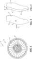
- FIG. 1 a perspective view of a fan 10 of a gas turbine engine 12 is shown.
- the fan 10 may be involved in using mechanical energy from a turbine (not shown) to accelerate air through the engine 12 to assist in generating thrust if used in an aircraft, or power if used in land-based operations.
- the fan 10 has a plurality of fan blades 15 radially extending from a hub 16, as shown.
- Fan blades 15 may be made from aluminum, titanium, a metal alloy, a composite material, or any other suitable composition.
- FIG. 2 shows an isolated fan blade 15 (without a protective sheath), illustrating a leading edge 18 of the fan blade 15.
- the fan blade leading edge 18 is the portion of the fan blade that first contacts air moving through the engine in the direction of arrow 19, as shown.
- the fan blade 15 may further have a leading surface 20 and a trailing surface 22, as shown.
- the leading surface 20 may be oriented toward the direction of fan rotation and the trailing surface 22 may be oriented away from the direction of fan rotation.
- leading edge 18 Upon impact with debris such as, for example, birds, hail, ice, or other objects in the environment, the leading edge 18 as well as the surfaces 20 and 22 may become damaged and thereby interfere with the operation of the gas turbine engine 12. Furthermore, the leading edge 18 and the surfaces 20 and 22 may be damaged by erosion caused by environmental exposure over a certain time.
- debris such as, for example, birds, hail, ice, or other objects in the environment
- FIG. 3 shows the leading edge 18 of the fan blade 15 provided with a protective sheath 30 in accordance with the present disclosure.
- the protective sheath 30 may structurally reinforce and stiffen the fan blade 15 and assist preventing damage to the fan blade 15 upon impact with debris and other objects encountered during the operation of the fan 10.
- the protective sheath 30 may further act to reduce the vibrational flutter of fan blade 15 and may assist preventing fan blade erosion.
- the protective sheath 30 may be formed from titanium, such as titanium 6A1-4V.
- the protective sheath 30 may be formed from a titanium alloy, a nickel alloy, nickel, or other suitable composition chosen by a skilled artisan.
- the protective sheath 30 may fit over the leading edge 18 in order to protect and structurally reinforce the fan blade 15 and may at least partially cover the surfaces 20 and 22 of the fan blade 15, as shown.
- the protective sheath 30 may be bonded or otherwise joined to the fan blade 15 with an adhesive or other suitable bonding arrangement. Alternatively, the protective sheath 30 may be engaged with the fan blade 15 without bonding.
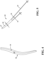
- the protective sheath 30 may have two wings which may include a longer first wing 32 and a shorter second wing 34, as best shown in FIG. 5 .
- the first wing 32 may at least partially cover the leading surface 20 of the fan blade 15, and the second wing 34 may at least partially cover the trailing surface 22 of the fan blade 15.
- the protective sheath 30 may have an ID slot 35 forming a cavity configured to receive the fan blade leading edge 18.
- the ID slot 35 may be delimited by the space between the first wing 32 and the second wing 34, as best shown in FIG. 5 .
- the ID slot 35 may have an inner contour that fully conforms to the contour of leading edge 18 such that an air tight seal may be formed when the protective sheath 30 is engaged with the fan blade 15.
- the protective sheath 30 may also have a contoured outer surface 37 having a shape that conforms to the contour of leading edge 18.
- the protective sheath 30 may have a leading edge nose 39 with a shape that conforms to the shape of the leading edge 18.
- the leading edge nose 39 may have a wall thickness A that is significantly greater than the wall thicknesses B of the wings 32 and 34.
- the relative wall thicknesses of the leading edge nose 39 to the wings 32/34 may be about three to one.
- the wings 32 and 34 may have a thickness B in the range of about 0.5 mm (0.02 inches) to about 1 mm (0.04 inches).
- the wall thicknesses and relative wall thicknesses of the leading edge nose 39 and the wings 32/34 may vary significantly.
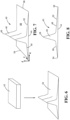
- FIG. 6 illustrates the formation of a preform plate 40 from a stock plate 42 in accordance with a method of the present disclosure.
- the preform plate 40 may serve as input stock material for the manufacture of the protective sheath 30 (see further details below).
- the preform plate 40 may be generated from the stock plate 42 by a contour roll plate technique, by hot forging (or press forging), conventional machining, or additive manufacturing, as will be discussed in further detail below.
- the stock plate 42 may be comprised of titanium, such as titanium-6Al-4V, or it may be comprised of a titanium alloy, a nickel alloy, nickel, or other suitable metallic composition.
- the preform plate 40 may have a length, a width, and a height along the x, y, and z axes, respectively, as best shown in FIG. 7 , and may have a flattened surface 44 and an inclined surface 46. Moreover, the inclined surface 46 may have a spike 48 projecting along the height (z) of the preform plate 40 that may come to an apex 49, as shown.
- the spike 48 may have a fixed shape, which may be approximately triangular in side view, and a fixed cross-sectional area across the width (y) of the preform plate 40, as shown. In the final protective sheath 30, the spike 48 may form the leading edge nose 39.
- the inclined surface 46 may have a first side 50 and a second side 52 which may be tapered and may become progressively thinner from the spike 48 towards the ends 54 and 56, respectively.
- the sides 50 and 52 may flank the spike 48, as shown.
- the sides 50 and 52 may ultimately form the wings 32 and 34, as will be discussed in further detail below.
- the shape of preform plate 40 may deviate from those shown in FIGs. 6-8 .
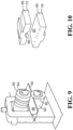
- the preform plate 40 may be generated from the stock plate 42 by a contour rolled plate technique, as depicted in FIG. 9 .
- the stock plate 42 which may initially have a uniform thickness, may first be passed through a series of rollers at a temperature conducive to plate deformation in order to progressively reduce the stock plate 42 to a desired thickness (process not shown).
- the thinned stock plate may then be passed between two roller dies 60, one roller die 60 having a flattened surface (flattened roller 62) to provide the flattened surface 44 of preform plate 40, and the other roller die 60 having an imprinted surface (imprinted roller 64) to provide the inclined surface 46 of the preform plate 40 (see FIG. 7 ).
- the thinned stock plate may be repeatedly passed between the roller dies 60 until the desired shape and dimensions of the preform plate 40 is generated.
- the contour rolled plate method may be performed at a temperature conducive to titanium plate deformation such as between about 815°C (1500°F) and about 930°C (1700°F) but other temperatures may also be suitable depending on the plate composition and other considerations. Given that nearly all of the input plate material is used to generate the preform plate 40 and the machinery used for the contour roll plate method is not expensive, the contour rolled plate technique may provide an efficient and inexpensive method to generate the preform plate 40.
- the preform plate 40 may be generated from the stock plate 42 by a hot forging (or press forging) technique.
- the hot forging technique may involve heating the stock plate 42 to a temperature that promotes superplasticity and subsequently pressing the heated stock plate 42 between two dies 65, exemplary illustrations of which are shown in FIG. 10 .
- One of the dies 65 (flattened die 70) may have a flattened surface 67 to form the flattened surface 44 of the preform plate 40 and the other die 65 (contoured die 72) may have a contoured surface 69 to form the inclined surface 46 of the preform plate 40.
- superplasticity may be achieved at about 900°C (1650°F).
- the optimal temperature range for hot forging may vary significantly.
- the skilled artisan will understand that, in practice, the shapes and dimensions of the dies 65 used for the hot forging technique may deviate from those shown in FIG. 10 .
- the preform plate 40 may be generated from the stock plate 42 by conventional machining whereby the preform plate 40 is carved out from the stock plate 42 using low cost machining tools.
- the preform plate 40 may be generated by additive manufacture in which the spike 48 may be built up layer by layer on an appropriately dimensioned metal sheet material by a cladding process or a selected welding process which may include 3D printing, electron beam welding, gas tungsten arc welding (GTAW), laser deposit welding, cold spraying, or other welding processes.
- GTAW gas tungsten arc welding
- the advantage of the additive manufacture method for generating the preform plate 40 may be a reduction in machining requirements and input stock material.
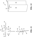
- a sheath intermediate 75 may be formed in accordance with the present disclosure, as shown in FIGs. 11 and 12 .
- the sheath intermediate 75 is the form the material of the preform plate 40 takes during the next manufacturing step towards the protective sheath 30.
- the sheath intermediate 75 may have intermediate wings 78 and 79 and a cavity 80 between intermediate the wings 78 and 79, as shown.
- the sheath intermediate 75 may have an outer surface 82 and an inner surface 84, as best shown in FIG. 12 .
- the outer surface 82 and the inner surface 84 may not have the curvature of the contoured outer surface 37 and the ID slot 35 of the protective sheath 30 once ultimately produced.
- the preform plate 40 may be converted to the sheath intermediate 75 by a cold forming process 86 or a warm forming process 88, as shown in FIG. 11 .
- the conversion of the preform plate 40 into the sheath intermediate 75 by the cold forming process 86 or the warm forming process 88 may involve bending the sides 50 and 52 in a direction away from the spike 48, as shown. This may be done over an appropriately shaped mandrel 90 using a press and a set of tools (tools not shown) and may introduce a bend 92 in the flattened surface 44, as shown.
- the cold forming process may be performed at room temperature, while the warm forming process may be performed at a selected elevated temperature conducive to the bending of the metallic material of preform plate 40.
- the selected elevated temperature may be chosen such that oxidation of the metallic material of preform plate 40 is avoided.
- the elevated temperatures for the warm forming process may be in the range of 93-815°C (200-1500°F) or may be even higher if warm forming is performed under a vacuum where metal oxidation is reduced.
- the temperature selected for the cold forming or warm forming process may vary significantly.
- the conversion of preform plate 40 to sheath intermediate 75 by the process shown in FIG. 11 is, according to the invention, performed without discarding any of the material of preform plate 40.
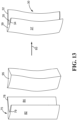
- a last step according to the present disclosure may be the formation of the protective sheath 30 from the sheath intermediate 75, as best shown in FIG. 13 .
- the sheath intermediate 75 may be converted to the protective sheath 30 by introducing curvature into the outer surface 82 and the inner surface 84 to provide the contoured outer surface 37 and the ID slot 35, as shown. Curvature may be introduced into the outer surface 82 and the inner surface 84 of the sheath intermediate 75 by a hot or superplastic forming process 93.
- the sheath intermediate 75 may be placed on a mandrel 95 which may be in the shape of the desired fan blade leading edge 18 and the sheath intermediate 75 may then be heated to a temperature that promotes superplasticity and metal deformation.
- a tool may be used to shape the outer surface 82 and the inner surface 84 of the heated sheath intermediate 75 over the mandrel 95 in order to form the contoured outer surface 37 and the ID slot 35, respectively, thereby providing the protective sheath 30.
- the superplastic forming process may be performed under air or vacuum and may be performed at a temperature in the range of between about 93°C (200°F) to about 930°C (1700°F), but other temperatures may also suffice depending on the composition of the protective sheath 30. Similar to the step for formation of the sheath intermediate 75 described above, it is important to note that the conversion of the sheath intermediate 75 to the protective sheath 30 by the process shown in FIG. 13 may be performed without discarding any of the material of sheath intermediate 75.
- the protective sheath 30 may be generated from the sheath intermediate 75 using a combination of a hard tool (i.e., mandrel 95) and a 'soft' tool such as a rubber pad or other similar relatively soft materials.
- a hard tool i.e., mandrel 95
- a 'soft' tool such as a rubber pad or other similar relatively soft materials.
- the sheath intermediate 75 may first be placed between the mandrel 95 and a soft tool and then pressure may be applied on the side of the soft tool by hydroforming or shock loading to force the sheath intermediate 75 to adopt the shape of the mandrel 95 and thereby develop the contoured outer surface 37 and the ID slot 35.
- the protective sheath 30 may also be also be directly generated from the preform plate 40 by superplastic formation such that the step forming the sheath intermediate 75 may be eliminated.
- the protective sheath 30 may be configured to receive the leading edge 18 of the fan blade 15 in the ID slot 35, as best shown in FIG. 3 .
- the protective sheath 30 may then be bonded or otherwise joined to the leading edge 18 using a suitable adhesive or other suitable arrangement.
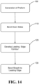
- FIG. 14 illustrates the steps which may be involved in the manufacture of the protective sheath 30, in accordance with the present disclosure.
- the preform plate 40 may be produced from the stock plate 42 by a contour rolled plate technique, a conventional machining process, or a hot forging process as described above.
- the preform plate 40 may also be generated by additive manufacture by building up the spike 48 layer by layer on an appropriately dimensioned metal sheet material.
- the sides 50 and 52 of the preform plate 40 may be bent down as shown by a block 110.
- the sides 50 and 52 of the preform plate 40 may be bent down by a cold or warm forming shaping process over the mandrel 90 to produce the sheath intermediate 75 (see FIG. 11 ).
- the outer surface 82 and the inner surface 84 of the sheath intermediate 75 may lack the curvature of the fan blade leading edge 18, during a block 120, the outer surface 82 and the inner surface 84 may be shaped over a mandrel 95 to develop the contoured outer surface 37 and the ID slot 35, thereby generating the protective sheath 30, as shown in FIG. 13 .
- the leading edge contour may be developed on the sheath intermediate 75 by placing it between an appropriately shaped mandrel (or hard tool) and a soft tool and subsequently applying pressure on the side of the soft tool to force the sheath intermediate 75 to adopt the shape of the mandrel.
- the contoured outer surface 37 and the ID slot 35 may have a contour matching the contour of the fan blade leading edge 18.
- the protective sheath 30 may then be bonded or otherwise joined to the leading edge 18 of the fan blade according to block 130, as shown.
- the technology disclosed herein has industrial applicability in a variety of settings including, but not limited to, aircraft and gas turbine engine construction.
- the generation of a protective leading edge sheath from a preform plate minimizes the amount of input stock material that is discarded in the manufacture process, reduces tooling costs, and increases production efficiency compared with currently known methods.
- the generation of protective sheaths from a preform plate provides straightforward access to protective sheaths having the desired change in cross-sectional area between the leading edge nose and the wings as well as access to ID slots having shapes and dimensions fully conforming to the shape of the fan blade leading edge.
Landscapes
- Engineering & Computer Science (AREA)
- Mechanical Engineering (AREA)
- General Engineering & Computer Science (AREA)
- Chemical & Material Sciences (AREA)
- Materials Engineering (AREA)
- Structures Of Non-Positive Displacement Pumps (AREA)
- Forging (AREA)
Claims (14)
- Verfahren zum Herstellen einer Schutzummantelung (30) für eine Gebläseschaufelanströmkante, umfassend:Erzeugen einer Vorformlingsplatte (40) aus einer Eingangsmaterialplatte (42), wobei die Vorformlingsplatte (40) eine ebene Fläche (44) und eine geneigte Fläche (46) aufweist, wobei die geneigte Fläche(46) eine Spitze (48) aufweist, die sich von der geneigten Fläche (46) weg erstreckt, wobei die Vorformlingsplatte (40) ferner eine erste Seite (50) und eine zweite Seite (52) beinhaltet, die die Spitze (48) flankieren;Biegen der ersten Seite (50) und der zweiten Seite (52) von der Spitze (48) weg, um eine Zwischenummantelung (75) zu erzeugen, wobei die Zwischenummantelung (75) aus der Vorformlingsplatte (40) erzeugt wird, ohne dass irgendein Material der Vorformlingsplatte (40) verworfen wird; undErzeugen der Schutzummantelung (30) aus der Zwischenummantelung (75) durch Formen einer Außenfläche (82) und einer Innenfläche (84) der Zwischenummantelung (75), um der Kontur der Gebläseschaufelanströmkante zu entsprechen.
- Verfahren nach Anspruch 1, wobei die geformte Innenfläche (84) einen Schlitz (35) mit innerem Durchmesser bildet, der konfiguriert ist, um die Gebläseschaufelanströmkante aufzunehmen.
- Verfahren nach Anspruch 2, wobei das Erzeugen der Schutzummantelung (30) aus der Zwischenummantelung (75) durch einen superplastischen Umformprozess durchgeführt wird.
- Verfahren nach Anspruch 3, wobei der superplastische Umformprozess umfasst:Aufsetzen der Zwischenummantelung (75) auf einen Dorn, der die Form der Gebläseschaufelanströmkante hat;Erhitzen der Zwischenummantelung (75) auf eine Temperatur, die eine superplastische Verformung begünstigt; undVerwenden eines Werkzeugs, um die Außenfläche (82) und die Innenfläche (84) der Zwischenummantelung (75) zu formen, um der Kontur der Gebläseschaufelanströmkante zu entsprechen.
- Verfahren nach Anspruch 3, wobei Biegen der ersten Seite (50) und der zweiten Seite (52) durch einen Kaltumformprozess über einen Dorn durchgeführt wird.
- Verfahren nach Anspruch 5, wobei der Kaltumformprozess bei Raumtemperatur durchgeführt wird.
- Verfahren nach Anspruch 3, wobei Biegen der ersten Seite (50) und der zweiten Seite (52) durch einen Warmumformprozess über einen Dorn durchgeführt wird.
- Verfahren nach Anspruch 7, wobei der Warmumformprozess zwischen etwa 200 °C und etwa 1500 °C durchgeführt wird.
- Verfahren nach Anspruch 3, wobei Erzeugen der Vorformlingsplatte (40) aus der Materialplatte (42) durch eine Konturwalzplattentechnik durchgeführt wird.
- Verfahren nach Anspruch 3, wobei Erzeugen der Vorformlingsplatte (40) aus der Materialplatte (42) durch ein Verfahren durchgeführt wird, das aus der Gruppe ausgewählt ist, die aus herkömmlicher maschineller Bearbeitung und Warmschmieden besteht.
- Verfahren nach Anspruch 10, ferner umfassend den Schritt des Verbindens der Schutzummantelung (30) mit der Gebläseschaufel unter Verwendung mindestens eines Klebstoffs.
- Verfahren nach Anspruch 10, wobei die Schutzummantelung (30) aus Titan geformt ist.
- Verfahren nach einem der vorhergehenden Ansprüche, wobei die Schutzummantelung (30) aus der Zwischenummantelung (75) ohne Verwerfen irgendeines Materials der Zwischenummantelung (75) erzeugt wird.
- Verfahren nach einem der vorhergehenden Ansprüche, wobei die Ummantelung (30) zwei Flügel beinhaltet, einschließlich eines längeren ersten Flügels (32) und eines kürzeren zweiten Flügels (34), die von der ersten Seite (50) und der zweiten Seite (52) gebildet werden.
Applications Claiming Priority (2)
| Application Number | Priority Date | Filing Date | Title |
|---|---|---|---|
| US201361787741P | 2013-03-15 | 2013-03-15 | |
| PCT/US2013/075325 WO2014143260A1 (en) | 2013-03-15 | 2013-12-16 | Leading edge sheath manufacturing method |
Publications (3)
| Publication Number | Publication Date |
|---|---|
| EP2969293A1 EP2969293A1 (de) | 2016-01-20 |
| EP2969293A4 EP2969293A4 (de) | 2016-11-23 |
| EP2969293B1 true EP2969293B1 (de) | 2024-04-17 |
Family
ID=51537449
Family Applications (1)
| Application Number | Title | Priority Date | Filing Date |
|---|---|---|---|
| EP13878459.0A Active EP2969293B1 (de) | 2013-03-15 | 2013-12-16 | Herstellungsverfahren für eine anströmkantenummantelung |
Country Status (3)
| Country | Link |
|---|---|
| US (1) | US10081082B2 (de) |
| EP (1) | EP2969293B1 (de) |
| WO (1) | WO2014143260A1 (de) |
Families Citing this family (12)
| Publication number | Priority date | Publication date | Assignee | Title |
|---|---|---|---|---|
| US9729506B2 (en) | 2014-08-22 | 2017-08-08 | Shape Security, Inc. | Application programming interface wall |
| US10815797B2 (en) | 2016-08-12 | 2020-10-27 | Hamilton Sundstrand Corporation | Airfoil systems and methods of assembly |
| US10900136B2 (en) | 2017-07-18 | 2021-01-26 | Honeywell International Inc. | Additive-based electroforming manufacturing methods and metallic articles produced thereby |
| TW201925632A (zh) | 2017-11-24 | 2019-07-01 | 和碩聯合科技股份有限公司 | 葉輪、風扇及扇葉片製作方法 |
| CN110645895B (zh) * | 2018-06-27 | 2021-05-14 | 中国航发商用航空发动机有限责任公司 | 风扇叶片前缘加强边鼻锥宽度的测量系统及测量方法 |
| US20200039641A1 (en) * | 2018-08-02 | 2020-02-06 | Bell Helicopter Textron Inc. | Abrasion strip and method of manufacturing the same |
| US11156100B2 (en) * | 2018-12-04 | 2021-10-26 | Raytheon Technologies Corporation | Composite fan blade |
| GB201900911D0 (en) | 2019-01-23 | 2019-03-13 | Rolls Royce Plc | A method of forming a protective sheath for an aerofoil component |
| US11753723B2 (en) * | 2020-06-02 | 2023-09-12 | The Boeing Company | Systems and methods for cold spray additive manufacture with superplastic formation diffusion bonding |
| FR3124217B1 (fr) * | 2021-06-21 | 2023-06-30 | Safran Aircraft Engines | Procede de fabrication d’une aube composite de turbomachine avec controle du poids moment |
| US11988103B2 (en) * | 2021-10-27 | 2024-05-21 | General Electric Company | Airfoils for a fan section of a turbine engine |
| FR3158249A1 (fr) | 2024-01-17 | 2025-07-18 | Safran Aircraft Engines | Procede de fabrication d’un renfort metallique pour une aube de turbomachine |
Family Cites Families (12)
| Publication number | Priority date | Publication date | Assignee | Title |
|---|---|---|---|---|
| US2422810A (en) | 1944-01-06 | 1947-06-24 | Smith Corp A O | Method of making propeller blades |
| US2463101A (en) | 1944-02-18 | 1949-03-01 | Smith Corp A O | Method of making airplane propellers |
| US2544447A (en) * | 1944-11-24 | 1951-03-06 | Curtiss Wright Corp | Apparatus for producing shaped sections |
| US5168741A (en) * | 1990-11-20 | 1992-12-08 | Braunheim Stephen T | Method for forming a leading edge cover for jet engine blades |
| US5694683A (en) | 1993-04-20 | 1997-12-09 | Chromalloy Gas Turbine Corporation | Hot forming process |
| US5908285A (en) | 1995-03-10 | 1999-06-01 | United Technologies Corporation | Electroformed sheath |
| US5881972A (en) | 1997-03-05 | 1999-03-16 | United Technologies Corporation | Electroformed sheath and airfoiled component construction |
| US8088498B2 (en) * | 2007-05-23 | 2012-01-03 | Hamilton Sundstrand Corporation | Electro-formed sheath for use on airfoil components |
| US9289816B2 (en) | 2009-01-22 | 2016-03-22 | Ihi Corporation | Production method of leading edge reinforcement of fan blade |
| US20110116906A1 (en) * | 2009-11-17 | 2011-05-19 | Smith Blair A | Airfoil component wear indicator |
| US9157327B2 (en) * | 2010-02-26 | 2015-10-13 | United Technologies Corporation | Hybrid metal fan blade |
| FR2970192B1 (fr) * | 2011-01-10 | 2013-12-13 | Snecma | Outillage et procede de forgeage a chaud de toles |
-
2013
- 2013-12-16 WO PCT/US2013/075325 patent/WO2014143260A1/en not_active Ceased
- 2013-12-16 US US14/768,633 patent/US10081082B2/en active Active
- 2013-12-16 EP EP13878459.0A patent/EP2969293B1/de active Active
Also Published As
| Publication number | Publication date |
|---|---|
| EP2969293A4 (de) | 2016-11-23 |
| US10081082B2 (en) | 2018-09-25 |
| WO2014143260A1 (en) | 2014-09-18 |
| US20160001407A1 (en) | 2016-01-07 |
| EP2969293A1 (de) | 2016-01-20 |
Similar Documents
| Publication | Publication Date | Title |
|---|---|---|
| EP2969293B1 (de) | Herstellungsverfahren für eine anströmkantenummantelung | |
| EP2229248B1 (de) | Verfahren zur herstellung einer metallischen vorderkante einer turbinenlüfterschaufel | |
| US5636440A (en) | Process for manufacturing a hollow blade for a turbo-machine | |
| US6467168B2 (en) | Method of manufacturing an article by diffusion bonding and superplastic forming | |
| EP1508400B1 (de) | Verfahren zur Herstellung eines Gegenstandes durch Diffusionsschweissen und superplastisches Verformen | |
| US5253419A (en) | Method of manufacturing a hollow blade for a turboshaft engine | |
| US6739049B2 (en) | Method of manufacturing an article by diffusion bonding and superplastic forming | |
| US4043498A (en) | Method of plastic flow diffusion bonding | |
| EP2223753A1 (de) | Verfahren und feuerfester Metallkern zur Erzeugung von Mikroschaltungen mit unterschiedlicher Dicke für Turbinenmotorkomponente | |
| RU2555274C1 (ru) | Способ изготовления полой вентиляторной лопатки | |
| EP1092485B1 (de) | Verfahren zur Herstellung eines Gegenstandes durch superplastische Formung und Diffusionsschweissung | |
| JP2005256838A (ja) | ファンブレードのための強化前縁部または後縁部を製造するための方法 | |
| EP1188497B1 (de) | Verfahren zur Herstellung eines Gegenstandes durch Diffusionsschweissung | |
| US20120174384A1 (en) | Tooling and a method for hot forging pieces of sheet metal | |
| US7578059B2 (en) | Method for manufacturing constituents of a hollow blade by rolling | |
| GB2269555A (en) | A method of manufacturing an article by superplastic forming and diffusion bonding | |
| CN106794545A (zh) | 制造前缘护罩的方法 | |
| US8683689B2 (en) | Method for manufacturing constituents of a hollow blade by press forging | |
| CN103476544B (zh) | 制作金属部件的方法 | |
| WO1994023890A1 (en) | Hot forming process | |
| CN116323089A (zh) | 用于生产进气唇缘的环形扇区的制造 | |
| EP2226134A2 (de) | Verfahren zur Herstellung einer Tragfläche | |
| US20100192351A1 (en) | Method for producing an annular wall structure | |
| WO2016156094A1 (en) | Method and apparatus for forming a compound curvature metal skin | |
| EP1605135B1 (de) | Herstellungsmethode und Zusammenbau von Turbinenblatt und Turbinenblattfuss |
Legal Events
| Date | Code | Title | Description |
|---|---|---|---|
| PUAI | Public reference made under article 153(3) epc to a published international application that has entered the european phase |
Free format text: ORIGINAL CODE: 0009012 |
|
| 17P | Request for examination filed |
Effective date: 20151009 |
|
| AK | Designated contracting states |
Kind code of ref document: A1 Designated state(s): AL AT BE BG CH CY CZ DE DK EE ES FI FR GB GR HR HU IE IS IT LI LT LU LV MC MK MT NL NO PL PT RO RS SE SI SK SM TR |
|
| AX | Request for extension of the european patent |
Extension state: BA ME |
|
| DAX | Request for extension of the european patent (deleted) | ||
| RAP1 | Party data changed (applicant data changed or rights of an application transferred) |
Owner name: UNITED TECHNOLOGIES CORPORATION |
|
| A4 | Supplementary search report drawn up and despatched |
Effective date: 20161025 |
|
| RIC1 | Information provided on ipc code assigned before grant |
Ipc: B21K 3/04 20060101ALN20161019BHEP Ipc: F04D 29/32 20060101ALI20161019BHEP Ipc: B23P 15/04 20060101AFI20161019BHEP Ipc: F01D 5/14 20060101ALI20161019BHEP Ipc: B21D 53/78 20060101ALN20161019BHEP |
|
| STAA | Information on the status of an ep patent application or granted ep patent |
Free format text: STATUS: EXAMINATION IS IN PROGRESS |
|
| 17Q | First examination report despatched |
Effective date: 20191009 |
|
| RAP1 | Party data changed (applicant data changed or rights of an application transferred) |
Owner name: RAYTHEON TECHNOLOGIES CORPORATION |
|
| REG | Reference to a national code |
Ref country code: DE Ref legal event code: R079 Free format text: PREVIOUS MAIN CLASS: B21D0053780000 Ipc: B23P0015040000 Ref country code: DE Ref legal event code: R079 Ref document number: 602013085599 Country of ref document: DE Free format text: PREVIOUS MAIN CLASS: B21D0053780000 Ipc: B23P0015040000 |
|
| GRAP | Despatch of communication of intention to grant a patent |
Free format text: ORIGINAL CODE: EPIDOSNIGR1 |
|
| STAA | Information on the status of an ep patent application or granted ep patent |
Free format text: STATUS: GRANT OF PATENT IS INTENDED |
|
| RIC1 | Information provided on ipc code assigned before grant |
Ipc: B21D 53/78 20060101ALN20230405BHEP Ipc: B21H 7/00 20060101ALN20230405BHEP Ipc: B21K 3/04 20060101ALN20230405BHEP Ipc: F01D 5/14 20060101ALI20230405BHEP Ipc: F04D 29/32 20060101ALI20230405BHEP Ipc: B23P 15/04 20060101AFI20230405BHEP |
|
| INTG | Intention to grant announced |
Effective date: 20230508 |
|
| RIN1 | Information on inventor provided before grant (corrected) |
Inventor name: FURRER, DAVID ULRICH Inventor name: HANSEN, JAMES O. |
|
| GRAJ | Information related to disapproval of communication of intention to grant by the applicant or resumption of examination proceedings by the epo deleted |
Free format text: ORIGINAL CODE: EPIDOSDIGR1 |
|
| STAA | Information on the status of an ep patent application or granted ep patent |
Free format text: STATUS: EXAMINATION IS IN PROGRESS |
|
| INTC | Intention to grant announced (deleted) | ||
| GRAP | Despatch of communication of intention to grant a patent |
Free format text: ORIGINAL CODE: EPIDOSNIGR1 |
|
| STAA | Information on the status of an ep patent application or granted ep patent |
Free format text: STATUS: GRANT OF PATENT IS INTENDED |
|
| RAP3 | Party data changed (applicant data changed or rights of an application transferred) |
Owner name: RTX CORPORATION |
|
| RIC1 | Information provided on ipc code assigned before grant |
Ipc: B21D 53/78 20060101ALN20231009BHEP Ipc: B21H 7/00 20060101ALN20231009BHEP Ipc: B21K 3/04 20060101ALN20231009BHEP Ipc: F01D 5/14 20060101ALI20231009BHEP Ipc: F04D 29/32 20060101ALI20231009BHEP Ipc: B23P 15/04 20060101AFI20231009BHEP |
|
| INTG | Intention to grant announced |
Effective date: 20231031 |
|
| GRAS | Grant fee paid |
Free format text: ORIGINAL CODE: EPIDOSNIGR3 |
|
| GRAA | (expected) grant |
Free format text: ORIGINAL CODE: 0009210 |
|
| STAA | Information on the status of an ep patent application or granted ep patent |
Free format text: STATUS: THE PATENT HAS BEEN GRANTED |
|
| AK | Designated contracting states |
Kind code of ref document: B1 Designated state(s): AL AT BE BG CH CY CZ DE DK EE ES FI FR GB GR HR HU IE IS IT LI LT LU LV MC MK MT NL NO PL PT RO RS SE SI SK SM TR |
|
| REG | Reference to a national code |
Ref country code: GB Ref legal event code: FG4D |
|
| REG | Reference to a national code |
Ref country code: CH Ref legal event code: EP |
|
| REG | Reference to a national code |
Ref country code: DE Ref legal event code: R096 Ref document number: 602013085599 Country of ref document: DE |
|
| REG | Reference to a national code |
Ref country code: IE Ref legal event code: FG4D |
|
| REG | Reference to a national code |
Ref country code: LT Ref legal event code: MG9D |
|
| REG | Reference to a national code |
Ref country code: NL Ref legal event code: MP Effective date: 20240417 |
|
| REG | Reference to a national code |
Ref country code: AT Ref legal event code: MK05 Ref document number: 1676803 Country of ref document: AT Kind code of ref document: T Effective date: 20240417 |
|
| PG25 | Lapsed in a contracting state [announced via postgrant information from national office to epo] |
Ref country code: NL Free format text: LAPSE BECAUSE OF FAILURE TO SUBMIT A TRANSLATION OF THE DESCRIPTION OR TO PAY THE FEE WITHIN THE PRESCRIBED TIME-LIMIT Effective date: 20240417 |
|
| PG25 | Lapsed in a contracting state [announced via postgrant information from national office to epo] |
Ref country code: NL Free format text: LAPSE BECAUSE OF FAILURE TO SUBMIT A TRANSLATION OF THE DESCRIPTION OR TO PAY THE FEE WITHIN THE PRESCRIBED TIME-LIMIT Effective date: 20240417 |
|
| PG25 | Lapsed in a contracting state [announced via postgrant information from national office to epo] |
Ref country code: IS Free format text: LAPSE BECAUSE OF FAILURE TO SUBMIT A TRANSLATION OF THE DESCRIPTION OR TO PAY THE FEE WITHIN THE PRESCRIBED TIME-LIMIT Effective date: 20240817 |
|
| PG25 | Lapsed in a contracting state [announced via postgrant information from national office to epo] |
Ref country code: BG Free format text: LAPSE BECAUSE OF FAILURE TO SUBMIT A TRANSLATION OF THE DESCRIPTION OR TO PAY THE FEE WITHIN THE PRESCRIBED TIME-LIMIT Effective date: 20240417 |
|
| PG25 | Lapsed in a contracting state [announced via postgrant information from national office to epo] |
Ref country code: HR Free format text: LAPSE BECAUSE OF FAILURE TO SUBMIT A TRANSLATION OF THE DESCRIPTION OR TO PAY THE FEE WITHIN THE PRESCRIBED TIME-LIMIT Effective date: 20240417 Ref country code: FI Free format text: LAPSE BECAUSE OF FAILURE TO SUBMIT A TRANSLATION OF THE DESCRIPTION OR TO PAY THE FEE WITHIN THE PRESCRIBED TIME-LIMIT Effective date: 20240417 |
|
| PG25 | Lapsed in a contracting state [announced via postgrant information from national office to epo] |
Ref country code: GR Free format text: LAPSE BECAUSE OF FAILURE TO SUBMIT A TRANSLATION OF THE DESCRIPTION OR TO PAY THE FEE WITHIN THE PRESCRIBED TIME-LIMIT Effective date: 20240718 |
|
| PG25 | Lapsed in a contracting state [announced via postgrant information from national office to epo] |
Ref country code: PT Free format text: LAPSE BECAUSE OF FAILURE TO SUBMIT A TRANSLATION OF THE DESCRIPTION OR TO PAY THE FEE WITHIN THE PRESCRIBED TIME-LIMIT Effective date: 20240819 |
|
| PG25 | Lapsed in a contracting state [announced via postgrant information from national office to epo] |
Ref country code: ES Free format text: LAPSE BECAUSE OF FAILURE TO SUBMIT A TRANSLATION OF THE DESCRIPTION OR TO PAY THE FEE WITHIN THE PRESCRIBED TIME-LIMIT Effective date: 20240417 |
|
| PG25 | Lapsed in a contracting state [announced via postgrant information from national office to epo] |
Ref country code: AT Free format text: LAPSE BECAUSE OF FAILURE TO SUBMIT A TRANSLATION OF THE DESCRIPTION OR TO PAY THE FEE WITHIN THE PRESCRIBED TIME-LIMIT Effective date: 20240417 |
|
| PG25 | Lapsed in a contracting state [announced via postgrant information from national office to epo] |
Ref country code: PL Free format text: LAPSE BECAUSE OF FAILURE TO SUBMIT A TRANSLATION OF THE DESCRIPTION OR TO PAY THE FEE WITHIN THE PRESCRIBED TIME-LIMIT Effective date: 20240417 |
|
| PG25 | Lapsed in a contracting state [announced via postgrant information from national office to epo] |
Ref country code: LV Free format text: LAPSE BECAUSE OF FAILURE TO SUBMIT A TRANSLATION OF THE DESCRIPTION OR TO PAY THE FEE WITHIN THE PRESCRIBED TIME-LIMIT Effective date: 20240417 |
|
| PG25 | Lapsed in a contracting state [announced via postgrant information from national office to epo] |
Ref country code: PT Free format text: LAPSE BECAUSE OF FAILURE TO SUBMIT A TRANSLATION OF THE DESCRIPTION OR TO PAY THE FEE WITHIN THE PRESCRIBED TIME-LIMIT Effective date: 20240819 Ref country code: PL Free format text: LAPSE BECAUSE OF FAILURE TO SUBMIT A TRANSLATION OF THE DESCRIPTION OR TO PAY THE FEE WITHIN THE PRESCRIBED TIME-LIMIT Effective date: 20240417 Ref country code: NO Free format text: LAPSE BECAUSE OF FAILURE TO SUBMIT A TRANSLATION OF THE DESCRIPTION OR TO PAY THE FEE WITHIN THE PRESCRIBED TIME-LIMIT Effective date: 20240717 Ref country code: LV Free format text: LAPSE BECAUSE OF FAILURE TO SUBMIT A TRANSLATION OF THE DESCRIPTION OR TO PAY THE FEE WITHIN THE PRESCRIBED TIME-LIMIT Effective date: 20240417 Ref country code: IS Free format text: LAPSE BECAUSE OF FAILURE TO SUBMIT A TRANSLATION OF THE DESCRIPTION OR TO PAY THE FEE WITHIN THE PRESCRIBED TIME-LIMIT Effective date: 20240817 Ref country code: HR Free format text: LAPSE BECAUSE OF FAILURE TO SUBMIT A TRANSLATION OF THE DESCRIPTION OR TO PAY THE FEE WITHIN THE PRESCRIBED TIME-LIMIT Effective date: 20240417 Ref country code: GR Free format text: LAPSE BECAUSE OF FAILURE TO SUBMIT A TRANSLATION OF THE DESCRIPTION OR TO PAY THE FEE WITHIN THE PRESCRIBED TIME-LIMIT Effective date: 20240718 Ref country code: FI Free format text: LAPSE BECAUSE OF FAILURE TO SUBMIT A TRANSLATION OF THE DESCRIPTION OR TO PAY THE FEE WITHIN THE PRESCRIBED TIME-LIMIT Effective date: 20240417 Ref country code: ES Free format text: LAPSE BECAUSE OF FAILURE TO SUBMIT A TRANSLATION OF THE DESCRIPTION OR TO PAY THE FEE WITHIN THE PRESCRIBED TIME-LIMIT Effective date: 20240417 Ref country code: BG Free format text: LAPSE BECAUSE OF FAILURE TO SUBMIT A TRANSLATION OF THE DESCRIPTION OR TO PAY THE FEE WITHIN THE PRESCRIBED TIME-LIMIT Effective date: 20240417 Ref country code: AT Free format text: LAPSE BECAUSE OF FAILURE TO SUBMIT A TRANSLATION OF THE DESCRIPTION OR TO PAY THE FEE WITHIN THE PRESCRIBED TIME-LIMIT Effective date: 20240417 Ref country code: RS Free format text: LAPSE BECAUSE OF FAILURE TO SUBMIT A TRANSLATION OF THE DESCRIPTION OR TO PAY THE FEE WITHIN THE PRESCRIBED TIME-LIMIT Effective date: 20240717 |
|
| PG25 | Lapsed in a contracting state [announced via postgrant information from national office to epo] |
Ref country code: DK Free format text: LAPSE BECAUSE OF FAILURE TO SUBMIT A TRANSLATION OF THE DESCRIPTION OR TO PAY THE FEE WITHIN THE PRESCRIBED TIME-LIMIT Effective date: 20240417 |
|
| REG | Reference to a national code |
Ref country code: DE Ref legal event code: R097 Ref document number: 602013085599 Country of ref document: DE |
|
| PG25 | Lapsed in a contracting state [announced via postgrant information from national office to epo] |
Ref country code: EE Free format text: LAPSE BECAUSE OF FAILURE TO SUBMIT A TRANSLATION OF THE DESCRIPTION OR TO PAY THE FEE WITHIN THE PRESCRIBED TIME-LIMIT Effective date: 20240417 |
|
| PG25 | Lapsed in a contracting state [announced via postgrant information from national office to epo] |
Ref country code: CZ Free format text: LAPSE BECAUSE OF FAILURE TO SUBMIT A TRANSLATION OF THE DESCRIPTION OR TO PAY THE FEE WITHIN THE PRESCRIBED TIME-LIMIT Effective date: 20240417 |
|
| PG25 | Lapsed in a contracting state [announced via postgrant information from national office to epo] |
Ref country code: SK Free format text: LAPSE BECAUSE OF FAILURE TO SUBMIT A TRANSLATION OF THE DESCRIPTION OR TO PAY THE FEE WITHIN THE PRESCRIBED TIME-LIMIT Effective date: 20240417 Ref country code: RO Free format text: LAPSE BECAUSE OF FAILURE TO SUBMIT A TRANSLATION OF THE DESCRIPTION OR TO PAY THE FEE WITHIN THE PRESCRIBED TIME-LIMIT Effective date: 20240417 |
|
| PG25 | Lapsed in a contracting state [announced via postgrant information from national office to epo] |
Ref country code: SM Free format text: LAPSE BECAUSE OF FAILURE TO SUBMIT A TRANSLATION OF THE DESCRIPTION OR TO PAY THE FEE WITHIN THE PRESCRIBED TIME-LIMIT Effective date: 20240417 |
|
| PG25 | Lapsed in a contracting state [announced via postgrant information from national office to epo] |
Ref country code: SM Free format text: LAPSE BECAUSE OF FAILURE TO SUBMIT A TRANSLATION OF THE DESCRIPTION OR TO PAY THE FEE WITHIN THE PRESCRIBED TIME-LIMIT Effective date: 20240417 Ref country code: SK Free format text: LAPSE BECAUSE OF FAILURE TO SUBMIT A TRANSLATION OF THE DESCRIPTION OR TO PAY THE FEE WITHIN THE PRESCRIBED TIME-LIMIT Effective date: 20240417 Ref country code: RO Free format text: LAPSE BECAUSE OF FAILURE TO SUBMIT A TRANSLATION OF THE DESCRIPTION OR TO PAY THE FEE WITHIN THE PRESCRIBED TIME-LIMIT Effective date: 20240417 Ref country code: EE Free format text: LAPSE BECAUSE OF FAILURE TO SUBMIT A TRANSLATION OF THE DESCRIPTION OR TO PAY THE FEE WITHIN THE PRESCRIBED TIME-LIMIT Effective date: 20240417 Ref country code: DK Free format text: LAPSE BECAUSE OF FAILURE TO SUBMIT A TRANSLATION OF THE DESCRIPTION OR TO PAY THE FEE WITHIN THE PRESCRIBED TIME-LIMIT Effective date: 20240417 Ref country code: CZ Free format text: LAPSE BECAUSE OF FAILURE TO SUBMIT A TRANSLATION OF THE DESCRIPTION OR TO PAY THE FEE WITHIN THE PRESCRIBED TIME-LIMIT Effective date: 20240417 |
|
| PG25 | Lapsed in a contracting state [announced via postgrant information from national office to epo] |
Ref country code: IT Free format text: LAPSE BECAUSE OF FAILURE TO SUBMIT A TRANSLATION OF THE DESCRIPTION OR TO PAY THE FEE WITHIN THE PRESCRIBED TIME-LIMIT Effective date: 20240417 |
|
| PLBE | No opposition filed within time limit |
Free format text: ORIGINAL CODE: 0009261 |
|
| STAA | Information on the status of an ep patent application or granted ep patent |
Free format text: STATUS: NO OPPOSITION FILED WITHIN TIME LIMIT |
|
| 26N | No opposition filed |
Effective date: 20250120 |
|
| PG25 | Lapsed in a contracting state [announced via postgrant information from national office to epo] |
Ref country code: SI Free format text: LAPSE BECAUSE OF FAILURE TO SUBMIT A TRANSLATION OF THE DESCRIPTION OR TO PAY THE FEE WITHIN THE PRESCRIBED TIME-LIMIT Effective date: 20240417 |
|
| PG25 | Lapsed in a contracting state [announced via postgrant information from national office to epo] |
Ref country code: MC Free format text: LAPSE BECAUSE OF FAILURE TO SUBMIT A TRANSLATION OF THE DESCRIPTION OR TO PAY THE FEE WITHIN THE PRESCRIBED TIME-LIMIT Effective date: 20240417 |
|
| REG | Reference to a national code |
Ref country code: CH Ref legal event code: PL |
|
| PG25 | Lapsed in a contracting state [announced via postgrant information from national office to epo] |
Ref country code: LU Free format text: LAPSE BECAUSE OF NON-PAYMENT OF DUE FEES Effective date: 20241216 |
|
| PG25 | Lapsed in a contracting state [announced via postgrant information from national office to epo] |
Ref country code: SE Free format text: LAPSE BECAUSE OF FAILURE TO SUBMIT A TRANSLATION OF THE DESCRIPTION OR TO PAY THE FEE WITHIN THE PRESCRIBED TIME-LIMIT Effective date: 20240417 |
|
| REG | Reference to a national code |
Ref country code: BE Ref legal event code: MM Effective date: 20241231 |
|
| PG25 | Lapsed in a contracting state [announced via postgrant information from national office to epo] |
Ref country code: BE Free format text: LAPSE BECAUSE OF NON-PAYMENT OF DUE FEES Effective date: 20241231 |
|
| PG25 | Lapsed in a contracting state [announced via postgrant information from national office to epo] |
Ref country code: CH Free format text: LAPSE BECAUSE OF NON-PAYMENT OF DUE FEES Effective date: 20241231 |
|
| PG25 | Lapsed in a contracting state [announced via postgrant information from national office to epo] |
Ref country code: IE Free format text: LAPSE BECAUSE OF NON-PAYMENT OF DUE FEES Effective date: 20241216 |
|
| PGFP | Annual fee paid to national office [announced via postgrant information from national office to epo] |
Ref country code: DE Payment date: 20251126 Year of fee payment: 13 |
|
| PGFP | Annual fee paid to national office [announced via postgrant information from national office to epo] |
Ref country code: GB Payment date: 20251120 Year of fee payment: 13 |
|
| PGFP | Annual fee paid to national office [announced via postgrant information from national office to epo] |
Ref country code: FR Payment date: 20251119 Year of fee payment: 13 |