EP2968974B1 - System für bruchinterne bewegungsverwaltung - Google Patents
System für bruchinterne bewegungsverwaltung Download PDFInfo
- Publication number
- EP2968974B1 EP2968974B1 EP14710548.0A EP14710548A EP2968974B1 EP 2968974 B1 EP2968974 B1 EP 2968974B1 EP 14710548 A EP14710548 A EP 14710548A EP 2968974 B1 EP2968974 B1 EP 2968974B1
- Authority
- EP
- European Patent Office
- Prior art keywords
- patient
- marker
- optical tracking
- tracking system
- relative
- Prior art date
- Legal status (The legal status is an assumption and is not a legal conclusion. Google has not performed a legal analysis and makes no representation as to the accuracy of the status listed.)
- Active
Links
- 230000033001 locomotion Effects 0.000 title claims description 57
- 239000003550 marker Substances 0.000 claims description 101
- 238000011282 treatment Methods 0.000 claims description 49
- 230000003287 optical effect Effects 0.000 claims description 48
- 238000001959 radiotherapy Methods 0.000 claims description 39
- 230000005855 radiation Effects 0.000 claims description 25
- 206010028980 Neoplasm Diseases 0.000 claims description 19
- 238000012544 monitoring process Methods 0.000 claims description 13
- 201000011510 cancer Diseases 0.000 claims description 10
- 238000012545 processing Methods 0.000 claims description 10
- 230000008859 change Effects 0.000 claims description 6
- 230000002045 lasting effect Effects 0.000 claims description 3
- 238000002710 external beam radiation therapy Methods 0.000 claims 1
- 238000002560 therapeutic procedure Methods 0.000 description 20
- 238000000034 method Methods 0.000 description 18
- 210000001519 tissue Anatomy 0.000 description 13
- 230000006378 damage Effects 0.000 description 11
- 238000001514 detection method Methods 0.000 description 10
- 238000001356 surgical procedure Methods 0.000 description 10
- 238000003384 imaging method Methods 0.000 description 8
- 238000007726 management method Methods 0.000 description 6
- 238000002717 stereotactic radiation Methods 0.000 description 4
- 230000002285 radioactive effect Effects 0.000 description 3
- 238000003325 tomography Methods 0.000 description 3
- 230000009471 action Effects 0.000 description 2
- 239000000853 adhesive Substances 0.000 description 2
- 230000001070 adhesive effect Effects 0.000 description 2
- 210000004556 brain Anatomy 0.000 description 2
- 238000011221 initial treatment Methods 0.000 description 2
- 230000000266 injurious effect Effects 0.000 description 2
- 230000003902 lesion Effects 0.000 description 2
- 238000012634 optical imaging Methods 0.000 description 2
- 231100001274 therapeutic index Toxicity 0.000 description 2
- 206010053648 Vascular occlusion Diseases 0.000 description 1
- 230000004071 biological effect Effects 0.000 description 1
- 239000003054 catalyst Substances 0.000 description 1
- 230000005779 cell damage Effects 0.000 description 1
- 230000007012 clinical effect Effects 0.000 description 1
- 238000004891 communication Methods 0.000 description 1
- 230000003111 delayed effect Effects 0.000 description 1
- 230000001419 dependent effect Effects 0.000 description 1
- 230000001066 destructive effect Effects 0.000 description 1
- 238000011161 development Methods 0.000 description 1
- 230000002349 favourable effect Effects 0.000 description 1
- 238000010191 image analysis Methods 0.000 description 1
- 230000001771 impaired effect Effects 0.000 description 1
- 208000014674 injury Diseases 0.000 description 1
- 238000007917 intracranial administration Methods 0.000 description 1
- 210000003205 muscle Anatomy 0.000 description 1
- 230000001613 neoplastic effect Effects 0.000 description 1
- 230000002085 persistent effect Effects 0.000 description 1
- 230000008569 process Effects 0.000 description 1
- 230000029058 respiratory gaseous exchange Effects 0.000 description 1
- 230000035945 sensitivity Effects 0.000 description 1
- 238000002719 stereotactic radiosurgery Methods 0.000 description 1
- 230000009466 transformation Effects 0.000 description 1
- 238000000844 transformation Methods 0.000 description 1
- 230000008733 trauma Effects 0.000 description 1
- 238000011277 treatment modality Methods 0.000 description 1
- 208000021331 vascular occlusion disease Diseases 0.000 description 1
- 230000037303 wrinkles Effects 0.000 description 1
Images


Classifications
-
- A—HUMAN NECESSITIES
- A61—MEDICAL OR VETERINARY SCIENCE; HYGIENE
- A61N—ELECTROTHERAPY; MAGNETOTHERAPY; RADIATION THERAPY; ULTRASOUND THERAPY
- A61N5/00—Radiation therapy
- A61N5/10—X-ray therapy; Gamma-ray therapy; Particle-irradiation therapy
- A61N5/1048—Monitoring, verifying, controlling systems and methods
- A61N5/1049—Monitoring, verifying, controlling systems and methods for verifying the position of the patient with respect to the radiation beam
-
- A—HUMAN NECESSITIES
- A61—MEDICAL OR VETERINARY SCIENCE; HYGIENE
- A61N—ELECTROTHERAPY; MAGNETOTHERAPY; RADIATION THERAPY; ULTRASOUND THERAPY
- A61N5/00—Radiation therapy
- A61N5/10—X-ray therapy; Gamma-ray therapy; Particle-irradiation therapy
- A61N5/1048—Monitoring, verifying, controlling systems and methods
- A61N5/1064—Monitoring, verifying, controlling systems and methods for adjusting radiation treatment in response to monitoring
- A61N5/1065—Beam adjustment
- A61N5/1067—Beam adjustment in real time, i.e. during treatment
-
- A—HUMAN NECESSITIES
- A61—MEDICAL OR VETERINARY SCIENCE; HYGIENE
- A61B—DIAGNOSIS; SURGERY; IDENTIFICATION
- A61B90/00—Instruments, implements or accessories specially adapted for surgery or diagnosis and not covered by any of the groups A61B1/00 - A61B50/00, e.g. for luxation treatment or for protecting wound edges
- A61B90/39—Markers, e.g. radio-opaque or breast lesions markers
- A61B2090/3937—Visible markers
- A61B2090/3945—Active visible markers, e.g. light emitting diodes
-
- A—HUMAN NECESSITIES
- A61—MEDICAL OR VETERINARY SCIENCE; HYGIENE
- A61N—ELECTROTHERAPY; MAGNETOTHERAPY; RADIATION THERAPY; ULTRASOUND THERAPY
- A61N5/00—Radiation therapy
- A61N5/10—X-ray therapy; Gamma-ray therapy; Particle-irradiation therapy
- A61N5/1048—Monitoring, verifying, controlling systems and methods
- A61N5/1049—Monitoring, verifying, controlling systems and methods for verifying the position of the patient with respect to the radiation beam
- A61N2005/1051—Monitoring, verifying, controlling systems and methods for verifying the position of the patient with respect to the radiation beam using an active marker
-
- A—HUMAN NECESSITIES
- A61—MEDICAL OR VETERINARY SCIENCE; HYGIENE
- A61N—ELECTROTHERAPY; MAGNETOTHERAPY; RADIATION THERAPY; ULTRASOUND THERAPY
- A61N5/00—Radiation therapy
- A61N5/10—X-ray therapy; Gamma-ray therapy; Particle-irradiation therapy
- A61N5/1048—Monitoring, verifying, controlling systems and methods
- A61N5/1049—Monitoring, verifying, controlling systems and methods for verifying the position of the patient with respect to the radiation beam
- A61N2005/1059—Monitoring, verifying, controlling systems and methods for verifying the position of the patient with respect to the radiation beam using cameras imaging the patient
-
- A—HUMAN NECESSITIES
- A61—MEDICAL OR VETERINARY SCIENCE; HYGIENE
- A61N—ELECTROTHERAPY; MAGNETOTHERAPY; RADIATION THERAPY; ULTRASOUND THERAPY
- A61N5/00—Radiation therapy
- A61N5/10—X-ray therapy; Gamma-ray therapy; Particle-irradiation therapy
- A61N2005/1092—Details
- A61N2005/1097—Means for immobilizing the patient
Definitions
- the present invention relates to the field of radiation therapy.
- the invention concerns systems for monitoring intra-fraction motions of patients in connection with radiation therapy systems.
- One system for external beam radiotherapy is sold under the name of Leksell Gamma Knife ® , which provides such surgery by means of gamma radiation.
- the radiation is emitted from a large number of fixed radioactive sources and is focused by means of collimators, i.e. passages or channels for obtaining a beam of limited cross section, towards a defined target or treatment volume.
- collimators i.e. passages or channels for obtaining a beam of limited cross section
- each of the sources provides a dose of gamma radiation insufficient to damage intervening tissue.
- tissue destruction occurs where the radiation beams from all radiation sources intersect or converge, causing the radiation to reach tissue-destructive levels.
- the point of convergence is hereinafter referred to as the "focus point".
- Such a radiation device is, for example, referred to and described in US 4,780,898 .
- LINAC linear accelerator
- Stereotactic radiation surgery is a minimally invasive treatment modality that allows delivery of a large single dose of radiation to a specific intracranial target while sparing surrounding tissue. Unlike conventional fractionated radiation therapy, stereotactic radiation surgery does not rely on, or exploit, the higher radiation sensitivity of neoplastic lesions relative to normal brain (therapeutic ratio). Its selective destruction depends primarily on sharply focused high-dose radiation and a steep dose gradient around the defined target. The biological effect is irreparable cellular damage and delayed vascular occlusion within the high-dose target volume. Because a therapeutic ratio is not required, traditionally radiation resistant lesions can be treated. Because destructive doses are used, however, any normal structure included in the target volume is subject to damage.
- the head of a patient is immobilized in a stereotactic instrument, which defines the location of the treatment volume in the head. Further, the patient is secured in a patient positioning unit, which moves the entire patient so as to position the treatment volume in coincidence with the focus point of the radiation unit of the radiation therapy system. Consequently, in radiation therapy systems, such as a LINAC system or a Leksell Gamma Knife ® system, it is of a high importance that the positioning unit is capable of position the treatment volume in coincidence with the focus point at a very high precision. This high precision must also be maintained over time.
- the radiation reaches and hits the target, i.e. the treatment volume, with a high precision and thereby spares the healthy tissue being adjacent to and/or surrounding the treatment volume.
- the patient must be immobilized during a therapy session and, moreover, the position of the head, or the part of the patient being under treatment, must be the same in a therapy session as in a reference position, i.e. the position during the session when the pictures to create the therapy plan were captured by means of, for example, Computerized Tomography Imaging (CT-imaging).
- CT-imaging Computerized Tomography Imaging
- a face mask adapted and shaped to be placed over the face (and shoulders) of the patient to thereby keep the patient in a substantially fixed position relative to the positioning system is used.
- IFMM intra-fraction motion management
- IFMM intra-fraction motion management
- the prior art systems may have problems in withstanding the gamma radiation generated in, for example, a Perfexion ® system (a radiation therapy system provided by the applicant). Further, the prior art systems are often bulky which makes it difficult to use them together with, for example, the Perfexion ® system.
- Another solution is to provide IR-markers on the mask and detect the movements by means of an IR-tracking system, for example, an IR camera.
- an IR-tracking system for example, an IR camera.
- surface tracking IFMM systems such as the C-rad catalyst are not suitable.
- An object of the present invention is to provide improved systems for intra-fraction motion detection with a high degree of accuracy and reliability so as to avoid or at least significantly reduce the risk of undesired damages to surrounding sensitive tissue.
- a further object of the present invention is to provide improved systems for intra-fraction motion detection that easily can be integrated into or be used together with a radiation therapy system such as the Perfexion ® system.
- Yet another object of the present invention is to provide improved systems for intra-fraction motion detection that can be manufactured at a low cost.
- Still another object of the present invention is to provide improved systems for intra-fraction motion management that are user-friendly and hence are easy to use for the medical personnel handling the radiation therapy system.
- Another object of the present invention is to provide improved systems for intra-fraction motion management that are comfortable for the patient during use thereof.
- a further object of the present invention is to provide improved systems for intra-fraction motion management that are compatible with imaging methods such as Computerized Tomography Imaging (CT-imaging) or Cone Beam Computerized Tomography Imaging (CBCT-imaging).
- imaging methods such as Computerized Tomography Imaging (CT-imaging) or Cone Beam Computerized Tomography Imaging (CBCT-imaging).
- Another object of the present invention is to provide non-ionization systems for intra-fraction motion management (i.e. motion detection during the treatment sessions).
- the systems according to the present invention are preferably used for monitoring intra-fraction motions of a patient in connection with treatment of cancer tumors of the patient in a radiation therapy system such as the Perfexion ® system.
- a radiation therapy system such as the Perfexion ® system.
- a system for monitoring intra-fraction motions of a patient in connection with treatment of treatment volumes such as cancer tumors of the patient in a radiation therapy system which radiation therapy system comprises a radiation therapy unit having a radiation target and a patient positioning unit for positioning a treatment volume in a patient in relation to the target in the radiation therapy unit.
- the system comprises at least one patient marker arranged to be attached to the patient and at least one reference marker which establishes the origin of a local coordinate system.
- the at least one reference marker is preferably arranged to be positioned in a fixed position relative to a patient fixation arrangement for fixation of the patient during treatment.
- An optical tracking system is arranged in a position such that images of the patient marker and the reference markers can be captured.
- a processing module is configured to determine a relative shift in position from the initial starting position within the coordinate system established by the reference marker. The movement is determined based on images captured by the optical tracking system, wherein any relative shift indicates that the patient or a part of the patient has moved
- the optical tracking system is preferably arranged in a position such that images of the patient marker, when the marker is provided on the nose of the patient, and at least one reference marker can be captured in an image.
- the optical tracking system is placed so that all markers are within the tracking volume in a position where all markers remain in view during the treatment session.
- the present invention is based on the insight that a movement of a patient marker provided on the nose tip of the patient indicates movement of the head.
- the nose is a part of the face that is not intended to be moved and is therefore not connected to a lot of muscles, like most other parts of the face. Movements of the nose are normally very small and temporary, i.e. any part of the nose that is being moved normally comes back to its original position quickly.
- the motion tracking of present invention is based on changes on the position of the patient marker relative to a coordinate system of a reference indicator (preferably a reference tool including the reference marker(s)).
- the reference indicator is preferably firmly attached to a fixation arrangement for fixating the patient.
- the optical tracking system is arranged such that both the patient marker and the reference indicator are captured in an image.
- motions of the patient are tracked by the optical tracking system by monitoring changes in the position of the patient marker relative to the reference indicator. That is, by continuously obtaining images of the patient (i.e. the patient marker) and the reference markers (for example arranged on a reference tool) at predetermined intervals and analyzing these images, patient motions can be detected and tracked over time.
- the patient marker and the reference marker(s) are reflective and the optical tracking system is an IR tracking system including an IR emitter and an IR detector, for example, an IR camera.
- the emitted IR light is reflected by the markers and can be captured by the IR detector.
- the markers can be identified in the images as light spots and these positions can then be used for determining position changes.
- each of the patient marker and the reference marker(s) comprises an IR emitter and the optical tracking system includes an IR detector, for example, an IR camera.
- the light emitted from the markers can be captured by the IR detector.
- the markers can be identified in the images as light spots and these positions can then be used for determining position changes.
- the optical tracking system comprises a camera.
- the camera will capture the markers in each image.
- the markers can be identified in the images, for example, using image analysis.
- a reference coordinate system origin at a reference tool including the reference markers is determined. Based on this reference point, the position of the patient marker within the coordinates determined by the reference tool is then calculated.
- the relative distance between subsequent patient marker positions is based on the position of the patient marker and the position of the reference coordinate system in the images.
- a reference coordinate system is created, which enables tracking of the patient marker in three dimensions. However, for example, during the tracking only the magnitude of the vector may be used.
- the patient in connection with a treatment session, is provided with a mask shaped to fit the face of the patient.
- the mask is placed on the face.
- the mask has a hole such that the nose of the patient is free, i.e. not covered by the mask when placed on the face of the patient and is able to move without touching the mask.
- the patient marker can easily be attached to the nose tip of the patient directly on the skin of the patient.
- the reference tool is configured to be mounted at the patient fixation arrangement in a fixed position.
- the reference tool comprises one or more reference markers (in embodiments the reference tool includes one, three, four or five markers but, however, more than five is of course conceivable) and is positioned in a fixed position relative the patient and the patient positioning unit.
- the reference tool may be attached to the patient fixation arrangement via a stand.
- the reference tool is removable and can thus be mounted to the patient fixation arrangement during treatment periods when the reference tool is actually used and can be removed when not used.
- the reference tool is firmly attached to the patient fixation arrangement.
- first and second reference tools are mounted at fixed positions relative to said patient fixation arrangement, wherein each reference tool includes at least one of said reference markers.
- the reference tool comprises first and second reference tool members, each comprising at least one of said reference markers. Consequently, at least two reference markers are positioned in defined positions relative to said patient fixation arrangement.
- the processing module is configured to determine a position of the patient marker relative to the coordinate system established by the at least two reference markers based on images captured by the optical tracking system.
- One or more of the reference tools or reference tool members may comprise two or more reference markers. The two or more reference markers may be arranged at different positions in the z-direction, i.e.
- reference markers are at different distances from the optical tracking system.
- This difference in distance may be achieved by means of the shape of the reference tool(s), e.g. the reference tool(s) being curved or having one or more protruding portions extending in the z-direction to which reference marker(s) are attached, and/or by countersinking reference marker(s), i.e. mounting the reference marker(s) in a recess or blind hole.
- the two or more reference markers may also be arranged at different positions in the y-direction.
- the reference tools or reference tool members may furthermore be spaced apart in the x-direction.
- the first and second reference tools may be adapted to be mounted at said patient fixation arrangement.
- the first and second reference tools may be adapted to be mounted at said patient positioning unit.
- the reference tools may furthermore be adapted to be mounted on opposite sides of the head or neck of said patient.
- the head of the patient is fixed using a stereotactic head frame instead of using a mask.
- the head frame is adapted to be mounted at the patient fixation arrangement.
- the reference marker(s) may be fixed directly to the head frame, i.e. without the use of one or more separate reference tools.
- the head frame may comprise two or more reference markers. The two or more reference markers may be arranged at different positions in the z-direction, i.e. in the lengthwise direction of the patient, such that the reference markers are at different distances from the optical tracking system. This difference in distance may be achieved by means of the shape of the head frame, e.g.
- the head frame having a curved portion or having one or more protruding portions extending in the z-direction to which reference marker(s) are attached, and/or by countersinking reference marker(s), i.e. mounting the reference marker(s) in a recess or blind hole.
- the two or more reference markers may also be arranged at different positions in the y-direction and/or in the x-direction. Having reference markers arranged spaced apart in two or more directions is advantageous to achieve a more precise determination of the position of the patient marker.
- the position of the patient marker relative to the reference tool is determined based on images captured by the optical tracking system, wherein changes in the relative position indicates that the patient or a part of the patient has moved.
- the relative distance (between initial and actual position of the patient marker) is presented on a presentation device and is continuously updated to allow an operator of the system to view an indication of patient motions.
- an interrupting signal is provided instructing the radiation therapy system to interrupt the treatment if a position change exceeding a predetermined limit and/or lasting at least a predetermined period of time is detected.
- the treatment can be immediately interrupted if the patient has moved such that the therapy volume, e.g. a cancer tumor, has been moved from the initial treatment position more than allowed, and hence potential damage to surrounding tissue can be avoided.
- an alert signal is provided if a position change exceeding a predetermined limit and/or lasting at least a predetermined period of time is detected.
- the medical personnel handling the radiation therapy system can be informed that the patient has moved such that the therapy volume, e.g. a cancer tumor, has been moved from the initial treatment position, which hence may cause damage to surrounding tissue.
- the alert signal thus notifies the medical personnel that the therapy may have to be interrupted and the patient repositioned before that therapy session is resumed.
- the alert signal may be an audible signal or a visible signal and message and may be an electrical signal to the control unit to interrupt the therapy.
- a distance or time interval change is determined to be a detected change if the change exceeds a predetermined limit and/or lasts at least a predetermined time interval.
- a radiation therapy system for which the present invention is applicable comprises a radiation therapy unit or radiation unit 10 and a patient positioning unit 20 will be described.
- the radiation unit 10 there are provided radioactive sources, radioactive source holders, a collimator body, and external shielding elements.
- the collimator body comprises a large number of collimator channels directed towards a common focus point, in a manner as is commonly known in the art.
- the collimator body also acts as a radiation shield preventing radiation from reaching the patient other than through the collimator channels.
- Examples of collimator arrangements in radiation therapy systems applicable to the present invention can be found in US Patent No. 6,931,096 .
- the present invention is also applicable to radiation therapy systems using other arrangements for collimating radiation into a focus point, such as disclosed in US Patent No. 4,780,898 .
- the patient positioning unit 20 comprises a rigid framework 22, a slidable or movable carriage 24, and motors (not shown) for moving the carriage 24 in relation to the framework 22.
- the carriage 24 is further provided with a patient bed 26 for carrying and moving the entire patient.
- a fixation arrangement 28 for receiving and fixing a patient fixation unit or interface unit, either directly or via an adaptor unit 42, see Fig. 3 .
- the coordinates of the fixation unit are defined by a fixation unit coordinate system, which through the fixed relationship with the treatment volume also is used for defining the outlines of the treatment volume.
- the fixation unit, and hence the fixation unit coordinate system is moved in relation to the fixed radiation focus point such that the focus point is accurately positioned in the intended coordinate of the fixation unit coordinate system.
- the fixation arrangement 28 comprises two engagement points 21, 23, which are arranged for preventing the patient fixation unit from translational and/or rotational movement in relation to the movable carriage 24.
- the described embodiment concerns a radiation therapy system for providing gamma radiation therapy to a target volume in the head of human patient.
- Such therapy is often referred to as stereotactic radiation surgery.
- the patient head is fixed in a fixation unit in the form of a stereotactic head frame, which comprises engagement points adapted for engagement with the engagement points 21, 23 of the radiation therapy system.
- the head of the patient is fixed in the stereotactic frame, which in turn is fixedly attached to the patient positioning unit via the engagement points 21, 23.
- the intra-fraction motion detection system 5 comprises at least one patient marker 30 placed and positioned relative to the positioning unit 20 on the nose of the patient 29 when placed in the positioning system 20.
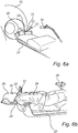
- the patient is provided with mask 39 (see Fig. 6b ) having a hole at the nose allowing that the marker 30 is placed on the nose of the patient 29.
- the patient marker 30 is preferably reflective patch of single use type with biocompatible adhesive.
- a reference tool 31 comprising reference markers 32 is positioned in a fixed position relative to the patient fixation arrangement 28 and the patient positioning unit 20.
- a reference tool 31 comprising three markers 32 is shown mounted to the patient fixation arrangement 28.
- the reference tool 31 may be attached to the patient fixation arrangement 28 via a stand 33.
- the reference tool 31 is removable and can thus be mounted to the patient fixation arrangement 28 during treatment periods when the reference tool 31 is actually used and can be removed when not used.
- the reference tool 31 is firmly attached to the patient fixation arrangement 28.
- An optical tracking system 34 is arranged in a position such that images of the patient marker 30, when the marker is provided on the nose of the patient 29, and the reference markers 32 of the reference tool 31 can be captured.
- a first reference tool 31a and a second reference tool 31b are mounted to the patient fixation arrangement 28, and thus in fixed positions relative to the patient positioning unit 20.
- the reference tools 31a-b are curved in the z-direction, i.e. in the lengthwise direction of the patient. Put differently, the reference tools are curved towards the optical tracking system 34 such that upper portions of the reference tools are closer to the optical tracking system than lower portions thereof.
- the reference tools 31a-b are mounted to the patient fixation arrangement 28 on opposite sides of the head and/or neck of the patient.
- Each reference tool comprises a first reference marker 32a, 32c attached to an upper portion or tip thereof, and a second reference marker 32b, 32d at a lower portion of said reference tool, i.e. closer to the patient positioning unit 20 when the reference tool is mounted to the patient fixation arrangement 28. Due to the curved shape of the reference tools, the first reference marker of each reference tool will be at a closer distance from the optical tracking system 34 than the second reference marker. In the embodiment shown in Fig. 9a and 9b , the second reference markers 32b, 32d are furthermore countersunk in the respective reference tool, i.e. mounted in a recess or blind hole, such that the difference in distance from the first and second reference markers to the optical tracking system is further increased.
- the reference tools may be removable and can thus be mounted to the patient fixation arrangement 28 during treatment periods when the reference tools are actually used and can be removed when not used.
- the reference tools may be firmly attached to the patient fixation arrangement 28.
- An optical tracking system 34 is arranged in a position such that images of the patient marker 30, when the marker is provided on the nose of the patient 29, and the reference markers 32a-d of the reference tool 31 can be captured.
- Fig. 10a and 10b another embodiment is shown.
- the patient is fixed to the patient fixation arrangement 28 using a stereotactic head frame 39.
- Four reference markers 32a-d are attached directly to the head frame in a symmetric manner.
- the two outer reference markers 32a, 32d are spaced apart in all three directions (X, Y and Z) from the inner two reference markers 32b, 32c.
- the two outer reference markers 32a, 32d are arranged closer to the optical tracking system than the two inner reference markers 32b, 32c.
- At least one patient marker 30 is placed and positioned relative to the positioning unit 20 on the nose of the patient 29 when placed in the positioning system 20. As can be seen in Figs.
- the head frame is configured to not obstruct the light path between the patient marker 30 and the optical tracking system 34.
- the patient marker 30 is preferably a reflective patch of single use type with biocompatible adhesive.
- An optical tracking system 34 is arranged in a position such that images of the patient marker 30, when the marker is provided on the nose of the patient 29, and the reference markers 32 of the reference tool 31 can be captured.
- a first reference tool 31a and a second reference tool 31b are mounted to the patient positioning unit 20.
- the reference tools 31a-b are mounted to the patient fixation arrangement 28 on opposite sides of the head/neck of the patient.
- Each reference tool comprises an upper protrusion 40a, 40c and a lower protrusion 40b, 40d.
- the protrusions are curved in the z-direction, i.e. in the lengthwise direction of the patient, thus towards the optical tracking system 34.
- Reference markers 32a-d are attached to the tip of each protrusion.
- the protrusions are configured such that the lower reference markers 32b, 32d are closer to the optical tracking system 34 than the upper reference markers 32a, 32c.
- An optical tracking system 34 is arranged in a position such that images of the patient marker 30, when the marker is provided on the nose of the patient 29, and the reference markers 32a-d of the reference tool 31 can be captured.
- the optical tracking system 34 is arranged in a position relative the patient positioning unit 20.
- the optical tracking system can be mounted to the patient positioning unit 20, for example, via a camera stand 35 attached to the patient positioning unit 20 using connection means 41 (see Fig. 7b ) such as a hinge or the like, which enable a user to position and lock the optical tracking system in a desired position (see also Fig. 6a, 6b , 7a and 7b ).
- the patient marker 30 is reflective and the optical tracking system is an IR tracking system including an IR emitter and an IR detector, for example, an IR camera.
- each of the patient marker and at least one reference marker comprises an IR emitter and the optical tracking system includes an IR detector, for example, an IR camera.
- the optical tracking system comprises a camera. Suitable tracking systems are manufactured, for example, by NDI Recognition Systems Inc.
- Figs. 7a and 7b an IR tracking system 34 according to embodiments of the present invention is shown in a folded down position ( Fig. 7a ) and a folded up position ( Fig. 7b ).
- Camera data such as, for example, data representing captured images are processed in a processing module 37 configured to determine the position of the patient marker relative to the coordinate system of the reference tool 31 and based on images captured by the optical tracking system and changes in that position indicates that the patient or a part of that patient has moved.
- the reference tool or at least one reference marker, is used to determine the origin of a coordinate system. Both the patient marker and the reference tool (i.e. at least one reference marker) are seen by the camera and captured in images. Based on these images, the patient marker's position is calculated within this coordinate system by performing the relevant transformations on the information provided by the camera.
- the processing module 37 may be arranged in an external unit 38, such as a personal computer or laptop, and image data can be transferred from the camera 34 to a communication module 36 of the external unit 38 wirelessly, e.g. using Bluetooth, or via cable.
- the processing module 37 may be implemented as a software module arranged to be executed on a computer unit such as a laptop or personal computer.
- the method can be used for intra-fraction motion detection and monitoring, for example, in therapy sessions during fractionated radiation therapy in connection with treatment of cancer.
- the method is preferably continued during the whole treatment session so as to monitor patient movements throughout the session.
- the patient 29 is placed on the patient positioning unit 20 and is positioned such that a treatment volume, e.g. the cancer tumor, is positioned in a treatment position in relation to the target volume in the radiation therapy unit 10.
- the patient is provided with a mask shaped to fit the face of the patient.
- the mask is provided with a hole such that the nose of the patient is free, i.e. not covered by the mask and such that the mask does not affect the movement of the nose so that the nose moves with the target, when the mask is placed on the face of the patient.
- the patient marker 30 is attached on the nose of the patient.
- the patient marker 30 is attached on the nose tip of the patient.
- Other methods for fixating the patient relative to the patient positioning unit 20 include invasive fixation or fixation using a bite-block.
- the reference tool 31 is mounted firmly to the patient fixation arrangement 28 such that the reference tool 31 is fixed relative to the patient positioning unit 20 in a desired position. If the reference tool 31 is not removable or if the reference tool 31 already is mounted to the patient fixation arrangement 28, this is not necessary. Further, the optical tracking system 34 is positioned (e.g. placed in a folded up position) in a position relative the patient and the reference tool such that both the patient marker 30 and the markers 32 of the reference tool 31 can be captured in an image.
- images of the patient marker 30 and reference markers of the reference tool 31 are repeatedly captured at predetermined time intervals.
- a position of the patient marker relative to its initial position is continuously determined based on the images captured by the optical tracking system 34. Changes in that distance indicate that the patient or a part of the patient has moved relative the patient positioning unit 20.
- the position of the patient marker relative to the reference tool is determined based on images captured by the optical tracking system 34.
- the patient marker movement can be presented on a presentation device during the treatment for an operator of the radiation therapy unit 10.
- the steps S130 and S140 are continuously repeated during the therapy session until the session has been terminated.
- the treatment it may be checked whether an observed motion exceeds a predetermined limit and/or lasts at least a predetermined period of time, i.e. whether the patient marker movement exceeds a predetermined limit and/or lasts at least a predetermined period of time. If a motion is observed that exceeds the predetermined limit and/or lasts the predetermined period of time, the treatment session may be interrupted and/or an alert signal may be issued.
- the external unit 38 may send an interruption signal to the radiation therapy system 10 instructing it to immediately interrupt the treatment. Thereby, it is secured that potential damage to surrounding tissue is minimized.
- the alert signal may be an audible and/or visible signal.
- the medical personnel performing the therapy are informed and alerted of the fact that the patient has moved from his initial therapy position, which may lead to impaired therapy, and may take proper actions.
- the treatment could also be automatically interrupted.
- the method can be used for intra-fraction motion detection and monitoring, for example, in therapy sessions during fractionated radiation therapy in connection with treatment of cancer.
- the method is preferably continued during the whole treatment session so as to monitor patient movements throughout the session.
- the patient 29 is placed on the patient positioning unit 20 and is positioned such that a treatment volume, e.g. the cancer tumor, is positioned in a treatment position in relation to the target volume in the radiation therapy unit 10.
- the patient is provided with a mask shaped to fit the face of the patient.
- the mask is provided with a hole such that the nose of the patient is free, i.e. not covered by the mask and such that the mask does not affect the movement of the nose so that the nose moves with the target, when the mask is placed on the face of the patient.
- the patient marker 30 is attached on the nose tip of the patient.
- Other methods for fixating the patient relative to the patient positioning unit 20 include invasive fixation or fixation using a bite-block.
- One method for fixating the patient relative to the patient positioning unit 20 is to use a stereotactic head frame, as shown in figures 10a-b and explained in further detail below.
- the reference marker(s) are positioned at fixed positions relative to the patient fixation arrangement 28 and/or the patient positioning unit 20. This may be achieved by mounting one or more reference tools, each including one or more reference marker, at the patient fixation arrangement 28 or directly to the patient positioning unit 20. If the reference tool 31 is not removable or if the reference tool(s) 31 is already mounted to the patient fixation arrangement 28, this is not necessary. Other methods for positioning the reference marker(s) include using a stereotactic head frame on which the reference marker(s) are arranged. If such a head frame is already mounted, no further action is needed to position the reference marker(s).
- optical tracking system 34 is positioned (e.g. placed in a folded up position) in a position relative the patient marker and the reference marker(s) such that both the patient marker 30 and the markers 32 of the reference tool 31 can be captured in an image.
- images of the patient marker 30 and reference markers are repeatedly captured at predetermined time intervals.
- a position of the patient marker relative to its initial position is continuously determined based on the images captured by the optical tracking system 34. Changes in that distance indicate that the patient or a part of the patient has moved relative the patient positioning unit 20.
- the position of the patient marker relative to the reference marker(s) is determined based on images captured by the optical tracking system 34.
- the patient marker movement can be presented on a presentation device during the treatment for an operator of the radiation therapy unit 10.
- the steps S230 and S240 are continuously repeated during the therapy session until the session has been terminated.
Landscapes
- Health & Medical Sciences (AREA)
- Engineering & Computer Science (AREA)
- Biomedical Technology (AREA)
- Pathology (AREA)
- Nuclear Medicine, Radiotherapy & Molecular Imaging (AREA)
- Radiology & Medical Imaging (AREA)
- Life Sciences & Earth Sciences (AREA)
- Animal Behavior & Ethology (AREA)
- General Health & Medical Sciences (AREA)
- Public Health (AREA)
- Veterinary Medicine (AREA)
- Radiation-Therapy Devices (AREA)
Claims (15)
- System (5) zum Überwachen von bruchinternen Bewegungen eines Patienten in Verbindung mit einer Behandlung von Behandlungsvolumen, wie z. B. Krebstumoren des Patienten, in einem Bestrahlungstherapiesystem, wobei das Strahlentherapiesystem eine Externstrahlen-Bestrahlungstherapieeinheit mit einem Bestrahlungsbrennpunkt und eine Patientenpositionierungseinheit zum Positionieren eines Behandlungsvolumens in einem Patienten in Bezug auf den Brennpunkt der Bestrahlungstherapieeinheit umfasst, wobei das System umfasst:eine Patientenfixieranordnung (28) für die Fixierung des Patienten während der Behandlung;mindestens einen Patientenmarker (30), der dazu vorgesehen ist, so an der Nase des Patienten angebracht zu sein, dass eine Bewegung des Patientenmarkers (30) eine Bewegung des Kopfs anzeigt;mindestens einen Referenzmarker (32), der dazu vorgesehen ist, in einer definierten Position relativ zu der Patientenfixieranordnung (28) positioniert zu sein;ein optisches Verfolgungssystem (34), das so in einer Position angeordnet ist, dass Bilder des mindestens einen Patientenmarkers, wenn sich der mindestens eine Patientenmarker (30) auf der Nase des Patienten befindet, und des mindestens einen Referenzmarkers (32) erfasst werden können,wobei die Position des optischen Verfolgungssystems (34) relativ zu dem mindestens einen Referenzmarker (32) festgelegt ist; undein Verarbeitungsmodul (37), das so ausgeführt ist, dass es eine Position des mindestens einen Patientenmarkers (30) relativ zu dem Koordinatensystem, das von dem mindestens einen Referenzmarker (32) gebildet wird, auf der Basis von Bildern bestimmt, die von dem optischen Verfolgungssystem (34) erfasst werden, wobei Veränderungen der Position Informationen darüber liefern, ob sich der Patient oder ein Teil des Patienten relativ zu der Patientenfixieranordnung (28) bewegt hat, wobei das Verarbeitungsmodul (37) so ausgeführt ist, dass es ein Unterbrechungssignal liefert, das das Bestrahlungstherapiesystem anweist, die Behandlung zu unterbrechen, wenn eine Bewegungsveränderung, die einen vorbestimmten Grenzwert überschreitet und/oder mindestens eine vorbestimmte Zeitperiode andauert, detektiert wird.
- System nach Anspruch 1, wobei der Patientenmarker reflektierend ist und das optische Verfolgungssystem ein IR-Verfolgungssystem ist, das einen IR-Emitter und einen IR-Detektor aufweist.
- System nach Anspruch 1, wobei der Patientenmarker und der mindestens eine Referenzmarker einen IR-Emitter umfassen und das optische Verfolgungssystem einen IR-Detektor aufweist.
- System nach Anspruch 1, wobei das optische Verfolgungssystem eine Kamera umfasst.
- System nach Anspruch 1, wobei das Verarbeitungsmodul so ausgeführt ist, dass es:eine mittlere Position des Referenzpunkts unter Verwendung der Referenzmarker bestimmt; undeine Position des Patientenmarkers relativ zu einem Koordinatensystem, das von dem Referenzpunkt bestimmt wird, bestimmt.
- System nach Anspruch 1, wobei ein Referenztool, das mindestens einen Referenzmarker aufweist, dazu vorgesehen ist, in einer festgelegten Position oder einer Position, die relativ zu der Patientenfixieranordnung definiert ist, an der Patientenfixieranordnung angebracht zu sein.
- System nach Anspruch 1, das ferner eine Darstellungsvorrichtung umfasst, die dazu vorgesehen ist, eine Anzeige von Patientenbewegungen darzustellen.
- System nach einem der Ansprüche 1-7, wobei das System mindestens zwei Referenzmarker umfasst, die dazu vorgesehen sind, in definierten Positionen relativ zu der Patientenfixieranordnung positioniert zu sein, und wobei das Verarbeitungsmodul so ausgeführt ist, dass es eine Position des Patientenmarkers relativ zu dem Koordinatensystem, das von den mindestens zwei Referenzmarkern gebildet wird, auf der Basis der Bilder, die von dem optischen Verfolgungssystem erfasst werden, bestimmt.
- System nach Anspruch 8, das ferner ein erstes und ein zweites Referenztool umfasst, die so ausgebildet sind, dass sie an festgelegten Positionen relativ zu der Patientenfixieranordnung angebracht sind, wobei jedes Referenztool mindestens einen der Referenzmarker aufweist.
- System nach Anspruch 9, wobei das erste und das zweite Referenztool so ausgebildet sind, dass sie an der Patientenfixieranordnung angebracht sind.
- System nach Anspruch 9, wobei das erste und das zweite Referenztool so ausgebildet sind, dass sie an der Patientenpositionierungseinheit angebracht sind.
- System nach einem der Ansprüche 9-11, wobei die Referenztools so ausgebildet sind, dass sie auf gegenüberliegenden Seiten des Kopfs oder Halses des Patienten angebracht sind.
- System nach einem der Ansprüche 9-12, wobei mindestens eines der Referenztools mindestens zwei Referenzmarker umfasst, die dazu vorgesehen sind, sich in unterschiedlichen Abständen zu dem optischen Verfolgungssystem zu befinden, wenn das (die) Referenztool(s) angebracht ist (sind).
- System nach Anspruch 8, das ferner einen stereotaktischen Kopfrahmen umfasst, der so ausgebildet ist, dass er an der Patientenfixieranordnung angebracht ist, wobei der Kopfrahmen so ausgebildet ist, dass er den Kopf des Patienten fixiert, wobei der Kopfrahmen die mindestens zwei Referenzmarker aufweist.
- System nach Anspruch 14, wobei die mindestens zwei Referenzmarker so an dem Kopfrahmen angeordnet sind, dass sie sich in unterschiedlichen Abständen zu dem optischen Verfolgungssystem befinden, wenn der Kopfrahmen angebracht ist.
Applications Claiming Priority (2)
| Application Number | Priority Date | Filing Date | Title |
|---|---|---|---|
| US13/835,685 US20140275698A1 (en) | 2013-03-15 | 2013-03-15 | Intra-fraction motion management system and method |
| PCT/EP2014/055085 WO2014140262A1 (en) | 2013-03-15 | 2014-03-14 | Intra-fraction motion management system and method |
Publications (2)
| Publication Number | Publication Date |
|---|---|
| EP2968974A1 EP2968974A1 (de) | 2016-01-20 |
| EP2968974B1 true EP2968974B1 (de) | 2017-05-03 |
Family
ID=50288064
Family Applications (1)
| Application Number | Title | Priority Date | Filing Date |
|---|---|---|---|
| EP14710548.0A Active EP2968974B1 (de) | 2013-03-15 | 2014-03-14 | System für bruchinterne bewegungsverwaltung |
Country Status (5)
| Country | Link |
|---|---|
| US (1) | US20140275698A1 (de) |
| EP (1) | EP2968974B1 (de) |
| JP (1) | JP6262777B2 (de) |
| CN (1) | CN105324155B (de) |
| WO (1) | WO2014140262A1 (de) |
Families Citing this family (15)
| Publication number | Priority date | Publication date | Assignee | Title |
|---|---|---|---|---|
| CN105302162B (zh) * | 2015-10-19 | 2017-12-12 | 江苏海明医疗器械有限公司 | 一种医用加速器机架的控制驱动方法 |
| CN105342631B (zh) * | 2015-11-30 | 2019-01-04 | 北京大学第一医院 | 一种放射线监测治疗系统 |
| CN106139414B (zh) * | 2016-06-23 | 2019-09-20 | 深圳市奥沃医学新技术发展有限公司 | 一种用于放疗系统的位置监测方法、装置和放疗系统 |
| CN209378331U (zh) * | 2017-11-10 | 2019-09-13 | 深圳市奥沃医学新技术发展有限公司 | 位置监测系统及放射治疗设备 |
| CN109496327A (zh) * | 2017-12-13 | 2019-03-19 | 上海联影医疗科技有限公司 | 用于诊断和治疗的系统和方法 |
| US11458334B2 (en) | 2017-12-13 | 2022-10-04 | Shanghai United Imaging Healthcare Co., Ltd. | System and method for diagnosis and treatment |
| CN108273199B (zh) | 2018-01-19 | 2024-05-14 | 深圳市奥沃医学新技术发展有限公司 | 一种位置检测方法、装置及放射治疗系统 |
| WO2020014934A1 (zh) * | 2018-07-19 | 2020-01-23 | 西安大医集团有限公司 | 一种肿瘤定位方法及装置 |
| US11938345B2 (en) | 2018-08-07 | 2024-03-26 | Our United Corporation | Method and apparatus for adjusting position, storage medium, and radiotherapy system |
| US11446094B2 (en) | 2019-05-02 | 2022-09-20 | Medtronic Navigation, Inc. | Nasal patient tracking device and method of using the same |
| US11547491B2 (en) | 2019-05-02 | 2023-01-10 | Medtronic Navigation, Inc. | Oral patient tracking device and method of using the same |
| WO2021056446A1 (zh) * | 2019-09-27 | 2021-04-01 | 西安大医集团股份有限公司 | 患者移动状态的检测方法、装置及系统 |
| CN112867536B (zh) * | 2019-09-27 | 2023-02-21 | 西安大医集团股份有限公司 | 患者移动状态的检测方法、装置及系统 |
| CN112263786B (zh) * | 2020-10-26 | 2022-11-25 | 中国人民解放军空军军医大学 | 一种食管癌治疗用定位装置 |
| DE102021109530A1 (de) * | 2021-04-15 | 2022-10-20 | Bodo Lippitz | Zahnschiene für Stereotaktische Radiotherapie und Radiochirurgie, Medizinisches System zur Lokalisierung einer Zielregion im Kopfbereich einer Person und Verfahren zum Lokalisieren einer Zielregion im Kopfbereich einer Person |
Family Cites Families (11)
| Publication number | Priority date | Publication date | Assignee | Title |
|---|---|---|---|---|
| US6143003A (en) * | 1995-01-31 | 2000-11-07 | Cosman; Eric R. | Repositioner for head, neck, and body |
| US5622187A (en) * | 1994-09-30 | 1997-04-22 | Nomos Corporation | Method and apparatus for patient positioning for radiation therapy |
| US5588430A (en) * | 1995-02-14 | 1996-12-31 | University Of Florida Research Foundation, Inc. | Repeat fixation for frameless stereotactic procedure |
| EP0836438B1 (de) * | 1996-04-29 | 2004-09-22 | Northern Digital Inc. | Bildgestenertes chirugisches system |
| US6980679B2 (en) * | 1998-10-23 | 2005-12-27 | Varian Medical System Technologies, Inc. | Method and system for monitoring breathing activity of a subject |
| US7024237B1 (en) * | 1999-10-29 | 2006-04-04 | University Of Florida Research Foundation, Inc. | Mask system and method for stereotactic radiotherapy and image guided procedures |
| US7073508B2 (en) * | 2004-06-25 | 2006-07-11 | Loma Linda University Medical Center | Method and device for registration and immobilization |
| JP2007236760A (ja) * | 2006-03-10 | 2007-09-20 | Mitsubishi Heavy Ind Ltd | 放射線治療装置制御装置および放射線照射方法 |
| CN101628154A (zh) * | 2008-07-16 | 2010-01-20 | 深圳市海博科技有限公司 | 基于预测的图像引导跟踪方法 |
| US7729473B2 (en) * | 2008-07-29 | 2010-06-01 | Elekta Ab (Publ) | Image-guided multi-source radiotherapy |
| CN102698375A (zh) * | 2012-06-05 | 2012-10-03 | 广东中能加速器科技有限公司 | 一种减少放射治疗中呼吸导致的照射偏差的方法和装置 |
-
2013
- 2013-03-15 US US13/835,685 patent/US20140275698A1/en not_active Abandoned
-
2014
- 2014-03-14 WO PCT/EP2014/055085 patent/WO2014140262A1/en active Application Filing
- 2014-03-14 CN CN201480015097.1A patent/CN105324155B/zh active Active
- 2014-03-14 JP JP2015562188A patent/JP6262777B2/ja active Active
- 2014-03-14 EP EP14710548.0A patent/EP2968974B1/de active Active
Also Published As
| Publication number | Publication date |
|---|---|
| JP2016513510A (ja) | 2016-05-16 |
| JP6262777B2 (ja) | 2018-01-17 |
| CN105324155A (zh) | 2016-02-10 |
| US20140275698A1 (en) | 2014-09-18 |
| EP2968974A1 (de) | 2016-01-20 |
| WO2014140262A1 (en) | 2014-09-18 |
| CN105324155B (zh) | 2019-09-17 |
Similar Documents
| Publication | Publication Date | Title |
|---|---|---|
| EP2968974B1 (de) | System für bruchinterne bewegungsverwaltung | |
| US10417357B2 (en) | Patient and procedure customized fixation and targeting devices for stereotactic frames | |
| US9511243B2 (en) | Prevention of setup errors in radiotherapy | |
| US10872427B2 (en) | Image guided patient setup for radiotherapy | |
| KR101621603B1 (ko) | 방사선 제어 및 최소화 시스템 및 그 방법 | |
| US7656998B2 (en) | Unified quality assurance for a radiation treatment delivery system | |
| JP3785136B2 (ja) | 放射線治療装置及び放射線治療装置の動作方法 | |
| US7853308B2 (en) | System and method for patient positioning for radiotherapy in the presence of respiratory motion | |
| US8831706B2 (en) | Fiducial-less tracking of a volume of interest | |
| US20030206614A1 (en) | Method and apparatus for alignment of medical radiation beams using a body frame | |
| US20140275707A1 (en) | Intra-fraction motion management system and method | |
| US20140213904A1 (en) | Intra-fraction motion management system | |
| WO2012119649A1 (en) | System and method for image-guided radio therapy | |
| EP3408832B1 (de) | Bildgeführte patienteneinrichtung für strahlentherapie | |
| WO2007044469A2 (en) | A method and apparatus to direct radiation treatment to a specific region of the brain | |
| Lee et al. | From frame to frameless: brain radiosurgery | |
| WO2013107472A1 (en) | Radiotherapeutic apparatus | |
| US12042673B2 (en) | Radiation therapy apparatus and radiation therapy method | |
| JP7553321B2 (ja) | セットアップ支援装置及びセットアップ支援方法 |
Legal Events
| Date | Code | Title | Description |
|---|---|---|---|
| PUAI | Public reference made under article 153(3) epc to a published international application that has entered the european phase |
Free format text: ORIGINAL CODE: 0009012 |
|
| 17P | Request for examination filed |
Effective date: 20150911 |
|
| AK | Designated contracting states |
Kind code of ref document: A1 Designated state(s): AL AT BE BG CH CY CZ DE DK EE ES FI FR GB GR HR HU IE IS IT LI LT LU LV MC MK MT NL NO PL PT RO RS SE SI SK SM TR |
|
| AX | Request for extension of the european patent |
Extension state: BA ME |
|
| RIN1 | Information on inventor provided before grant (corrected) |
Inventor name: LIDSTROEM, MATTIAS Inventor name: ARN, THOMAS Inventor name: FRENCH, MALCOLM Inventor name: GORKA, BARTOSZ Inventor name: CHEN, RUI |
|
| DAX | Request for extension of the european patent (deleted) | ||
| GRAP | Despatch of communication of intention to grant a patent |
Free format text: ORIGINAL CODE: EPIDOSNIGR1 |
|
| INTG | Intention to grant announced |
Effective date: 20161025 |
|
| RIN1 | Information on inventor provided before grant (corrected) |
Inventor name: GORKA, BARTOSZ Inventor name: LIDSTROEM, MATTIAS Inventor name: CHEN, RUI Inventor name: FRENCH, MALCOLM Inventor name: ARN, THOMAS |
|
| GRAS | Grant fee paid |
Free format text: ORIGINAL CODE: EPIDOSNIGR3 |
|
| GRAA | (expected) grant |
Free format text: ORIGINAL CODE: 0009210 |
|
| AK | Designated contracting states |
Kind code of ref document: B1 Designated state(s): AL AT BE BG CH CY CZ DE DK EE ES FI FR GB GR HR HU IE IS IT LI LT LU LV MC MK MT NL NO PL PT RO RS SE SI SK SM TR |
|
| REG | Reference to a national code |
Ref country code: GB Ref legal event code: FG4D |
|
| REG | Reference to a national code |
Ref country code: AT Ref legal event code: REF Ref document number: 889309 Country of ref document: AT Kind code of ref document: T Effective date: 20170515 Ref country code: CH Ref legal event code: EP |
|
| REG | Reference to a national code |
Ref country code: IE Ref legal event code: FG4D |
|
| REG | Reference to a national code |
Ref country code: DE Ref legal event code: R096 Ref document number: 602014009300 Country of ref document: DE |
|
| REG | Reference to a national code |
Ref country code: NL Ref legal event code: MP Effective date: 20170503 |
|
| REG | Reference to a national code |
Ref country code: AT Ref legal event code: MK05 Ref document number: 889309 Country of ref document: AT Kind code of ref document: T Effective date: 20170503 |
|
| REG | Reference to a national code |
Ref country code: LT Ref legal event code: MG4D |
|
| PG25 | Lapsed in a contracting state [announced via postgrant information from national office to epo] |
Ref country code: GR Free format text: LAPSE BECAUSE OF FAILURE TO SUBMIT A TRANSLATION OF THE DESCRIPTION OR TO PAY THE FEE WITHIN THE PRESCRIBED TIME-LIMIT Effective date: 20170804 Ref country code: HR Free format text: LAPSE BECAUSE OF FAILURE TO SUBMIT A TRANSLATION OF THE DESCRIPTION OR TO PAY THE FEE WITHIN THE PRESCRIBED TIME-LIMIT Effective date: 20170503 Ref country code: LT Free format text: LAPSE BECAUSE OF FAILURE TO SUBMIT A TRANSLATION OF THE DESCRIPTION OR TO PAY THE FEE WITHIN THE PRESCRIBED TIME-LIMIT Effective date: 20170503 Ref country code: NO Free format text: LAPSE BECAUSE OF FAILURE TO SUBMIT A TRANSLATION OF THE DESCRIPTION OR TO PAY THE FEE WITHIN THE PRESCRIBED TIME-LIMIT Effective date: 20170803 Ref country code: FI Free format text: LAPSE BECAUSE OF FAILURE TO SUBMIT A TRANSLATION OF THE DESCRIPTION OR TO PAY THE FEE WITHIN THE PRESCRIBED TIME-LIMIT Effective date: 20170503 Ref country code: ES Free format text: LAPSE BECAUSE OF FAILURE TO SUBMIT A TRANSLATION OF THE DESCRIPTION OR TO PAY THE FEE WITHIN THE PRESCRIBED TIME-LIMIT Effective date: 20170503 Ref country code: AT Free format text: LAPSE BECAUSE OF FAILURE TO SUBMIT A TRANSLATION OF THE DESCRIPTION OR TO PAY THE FEE WITHIN THE PRESCRIBED TIME-LIMIT Effective date: 20170503 |
|
| PG25 | Lapsed in a contracting state [announced via postgrant information from national office to epo] |
Ref country code: RS Free format text: LAPSE BECAUSE OF FAILURE TO SUBMIT A TRANSLATION OF THE DESCRIPTION OR TO PAY THE FEE WITHIN THE PRESCRIBED TIME-LIMIT Effective date: 20170503 Ref country code: NL Free format text: LAPSE BECAUSE OF FAILURE TO SUBMIT A TRANSLATION OF THE DESCRIPTION OR TO PAY THE FEE WITHIN THE PRESCRIBED TIME-LIMIT Effective date: 20170503 Ref country code: PL Free format text: LAPSE BECAUSE OF FAILURE TO SUBMIT A TRANSLATION OF THE DESCRIPTION OR TO PAY THE FEE WITHIN THE PRESCRIBED TIME-LIMIT Effective date: 20170503 Ref country code: LV Free format text: LAPSE BECAUSE OF FAILURE TO SUBMIT A TRANSLATION OF THE DESCRIPTION OR TO PAY THE FEE WITHIN THE PRESCRIBED TIME-LIMIT Effective date: 20170503 Ref country code: SE Free format text: LAPSE BECAUSE OF FAILURE TO SUBMIT A TRANSLATION OF THE DESCRIPTION OR TO PAY THE FEE WITHIN THE PRESCRIBED TIME-LIMIT Effective date: 20170503 Ref country code: BG Free format text: LAPSE BECAUSE OF FAILURE TO SUBMIT A TRANSLATION OF THE DESCRIPTION OR TO PAY THE FEE WITHIN THE PRESCRIBED TIME-LIMIT Effective date: 20170803 Ref country code: IS Free format text: LAPSE BECAUSE OF FAILURE TO SUBMIT A TRANSLATION OF THE DESCRIPTION OR TO PAY THE FEE WITHIN THE PRESCRIBED TIME-LIMIT Effective date: 20170903 |
|
| PG25 | Lapsed in a contracting state [announced via postgrant information from national office to epo] |
Ref country code: SK Free format text: LAPSE BECAUSE OF FAILURE TO SUBMIT A TRANSLATION OF THE DESCRIPTION OR TO PAY THE FEE WITHIN THE PRESCRIBED TIME-LIMIT Effective date: 20170503 Ref country code: RO Free format text: LAPSE BECAUSE OF FAILURE TO SUBMIT A TRANSLATION OF THE DESCRIPTION OR TO PAY THE FEE WITHIN THE PRESCRIBED TIME-LIMIT Effective date: 20170503 Ref country code: EE Free format text: LAPSE BECAUSE OF FAILURE TO SUBMIT A TRANSLATION OF THE DESCRIPTION OR TO PAY THE FEE WITHIN THE PRESCRIBED TIME-LIMIT Effective date: 20170503 Ref country code: CZ Free format text: LAPSE BECAUSE OF FAILURE TO SUBMIT A TRANSLATION OF THE DESCRIPTION OR TO PAY THE FEE WITHIN THE PRESCRIBED TIME-LIMIT Effective date: 20170503 Ref country code: DK Free format text: LAPSE BECAUSE OF FAILURE TO SUBMIT A TRANSLATION OF THE DESCRIPTION OR TO PAY THE FEE WITHIN THE PRESCRIBED TIME-LIMIT Effective date: 20170503 |
|
| REG | Reference to a national code |
Ref country code: DE Ref legal event code: R097 Ref document number: 602014009300 Country of ref document: DE |
|
| PG25 | Lapsed in a contracting state [announced via postgrant information from national office to epo] |
Ref country code: IT Free format text: LAPSE BECAUSE OF FAILURE TO SUBMIT A TRANSLATION OF THE DESCRIPTION OR TO PAY THE FEE WITHIN THE PRESCRIBED TIME-LIMIT Effective date: 20170503 Ref country code: SM Free format text: LAPSE BECAUSE OF FAILURE TO SUBMIT A TRANSLATION OF THE DESCRIPTION OR TO PAY THE FEE WITHIN THE PRESCRIBED TIME-LIMIT Effective date: 20170503 |
|
| PLBE | No opposition filed within time limit |
Free format text: ORIGINAL CODE: 0009261 |
|
| STAA | Information on the status of an ep patent application or granted ep patent |
Free format text: STATUS: NO OPPOSITION FILED WITHIN TIME LIMIT |
|
| REG | Reference to a national code |
Ref country code: FR Ref legal event code: PLFP Year of fee payment: 5 |
|
| 26N | No opposition filed |
Effective date: 20180206 |
|
| PG25 | Lapsed in a contracting state [announced via postgrant information from national office to epo] |
Ref country code: SI Free format text: LAPSE BECAUSE OF FAILURE TO SUBMIT A TRANSLATION OF THE DESCRIPTION OR TO PAY THE FEE WITHIN THE PRESCRIBED TIME-LIMIT Effective date: 20170503 |
|
| REG | Reference to a national code |
Ref country code: CH Ref legal event code: PL |
|
| PG25 | Lapsed in a contracting state [announced via postgrant information from national office to epo] |
Ref country code: MC Free format text: LAPSE BECAUSE OF FAILURE TO SUBMIT A TRANSLATION OF THE DESCRIPTION OR TO PAY THE FEE WITHIN THE PRESCRIBED TIME-LIMIT Effective date: 20170503 |
|
| REG | Reference to a national code |
Ref country code: BE Ref legal event code: MM Effective date: 20180331 |
|
| REG | Reference to a national code |
Ref country code: IE Ref legal event code: MM4A |
|
| PG25 | Lapsed in a contracting state [announced via postgrant information from national office to epo] |
Ref country code: LU Free format text: LAPSE BECAUSE OF NON-PAYMENT OF DUE FEES Effective date: 20180314 |
|
| PG25 | Lapsed in a contracting state [announced via postgrant information from national office to epo] |
Ref country code: IE Free format text: LAPSE BECAUSE OF NON-PAYMENT OF DUE FEES Effective date: 20180314 |
|
| PG25 | Lapsed in a contracting state [announced via postgrant information from national office to epo] |
Ref country code: CH Free format text: LAPSE BECAUSE OF NON-PAYMENT OF DUE FEES Effective date: 20180331 Ref country code: LI Free format text: LAPSE BECAUSE OF NON-PAYMENT OF DUE FEES Effective date: 20180331 Ref country code: BE Free format text: LAPSE BECAUSE OF NON-PAYMENT OF DUE FEES Effective date: 20180331 |
|
| PG25 | Lapsed in a contracting state [announced via postgrant information from national office to epo] |
Ref country code: MT Free format text: LAPSE BECAUSE OF NON-PAYMENT OF DUE FEES Effective date: 20180314 |
|
| PG25 | Lapsed in a contracting state [announced via postgrant information from national office to epo] |
Ref country code: TR Free format text: LAPSE BECAUSE OF FAILURE TO SUBMIT A TRANSLATION OF THE DESCRIPTION OR TO PAY THE FEE WITHIN THE PRESCRIBED TIME-LIMIT Effective date: 20170503 |
|
| PG25 | Lapsed in a contracting state [announced via postgrant information from national office to epo] |
Ref country code: PT Free format text: LAPSE BECAUSE OF FAILURE TO SUBMIT A TRANSLATION OF THE DESCRIPTION OR TO PAY THE FEE WITHIN THE PRESCRIBED TIME-LIMIT Effective date: 20170503 |
|
| PG25 | Lapsed in a contracting state [announced via postgrant information from national office to epo] |
Ref country code: CY Free format text: LAPSE BECAUSE OF FAILURE TO SUBMIT A TRANSLATION OF THE DESCRIPTION OR TO PAY THE FEE WITHIN THE PRESCRIBED TIME-LIMIT Effective date: 20170503 Ref country code: HU Free format text: LAPSE BECAUSE OF FAILURE TO SUBMIT A TRANSLATION OF THE DESCRIPTION OR TO PAY THE FEE WITHIN THE PRESCRIBED TIME-LIMIT; INVALID AB INITIO Effective date: 20140314 Ref country code: MK Free format text: LAPSE BECAUSE OF NON-PAYMENT OF DUE FEES Effective date: 20170503 |
|
| PG25 | Lapsed in a contracting state [announced via postgrant information from national office to epo] |
Ref country code: AL Free format text: LAPSE BECAUSE OF FAILURE TO SUBMIT A TRANSLATION OF THE DESCRIPTION OR TO PAY THE FEE WITHIN THE PRESCRIBED TIME-LIMIT Effective date: 20170503 |
|
| P01 | Opt-out of the competence of the unified patent court (upc) registered |
Effective date: 20230529 |
|
| PGFP | Annual fee paid to national office [announced via postgrant information from national office to epo] |
Ref country code: FR Payment date: 20231229 Year of fee payment: 11 |
|
| PGFP | Annual fee paid to national office [announced via postgrant information from national office to epo] |
Ref country code: DE Payment date: 20231229 Year of fee payment: 11 Ref country code: GB Payment date: 20240108 Year of fee payment: 11 |