EP2968846B1 - Medical device having a support structure - Google Patents
Medical device having a support structure Download PDFInfo
- Publication number
- EP2968846B1 EP2968846B1 EP14763003.2A EP14763003A EP2968846B1 EP 2968846 B1 EP2968846 B1 EP 2968846B1 EP 14763003 A EP14763003 A EP 14763003A EP 2968846 B1 EP2968846 B1 EP 2968846B1
- Authority
- EP
- European Patent Office
- Prior art keywords
- elongate member
- medical device
- support spine
- lumen
- support
- Prior art date
- Legal status (The legal status is an assumption and is not a legal conclusion. Google has not performed a legal analysis and makes no representation as to the accuracy of the status listed.)
- Active
Links
- 239000012530 fluid Substances 0.000 claims description 43
- 125000006850 spacer group Chemical group 0.000 claims description 23
- 238000004891 communication Methods 0.000 claims description 16
- 238000005452 bending Methods 0.000 claims description 11
- 230000007246 mechanism Effects 0.000 claims description 8
- 210000003361 heart septum Anatomy 0.000 claims description 2
- 208000011316 hemodynamic instability Diseases 0.000 claims description 2
- 238000010186 staining Methods 0.000 claims description 2
- 238000000034 method Methods 0.000 description 27
- 239000000463 material Substances 0.000 description 26
- 238000009413 insulation Methods 0.000 description 18
- 239000003550 marker Substances 0.000 description 18
- 238000003466 welding Methods 0.000 description 11
- BASFCYQUMIYNBI-UHFFFAOYSA-N platinum Chemical compound [Pt] BASFCYQUMIYNBI-UHFFFAOYSA-N 0.000 description 10
- 230000006870 function Effects 0.000 description 9
- 239000011295 pitch Substances 0.000 description 9
- 238000003384 imaging method Methods 0.000 description 8
- 210000005166 vasculature Anatomy 0.000 description 8
- 230000037361 pathway Effects 0.000 description 7
- 239000004020 conductor Substances 0.000 description 6
- 230000000694 effects Effects 0.000 description 6
- 239000012811 non-conductive material Substances 0.000 description 6
- 229910052697 platinum Inorganic materials 0.000 description 5
- 238000005520 cutting process Methods 0.000 description 4
- 230000009977 dual effect Effects 0.000 description 4
- 230000036772 blood pressure Effects 0.000 description 3
- 230000000747 cardiac effect Effects 0.000 description 3
- 239000000919 ceramic Substances 0.000 description 3
- 238000010586 diagram Methods 0.000 description 3
- 210000005246 left atrium Anatomy 0.000 description 3
- 238000004519 manufacturing process Methods 0.000 description 3
- HLXZNVUGXRDIFK-UHFFFAOYSA-N nickel titanium Chemical compound [Ti].[Ti].[Ti].[Ti].[Ti].[Ti].[Ti].[Ti].[Ti].[Ti].[Ti].[Ni].[Ni].[Ni].[Ni].[Ni].[Ni].[Ni].[Ni].[Ni].[Ni].[Ni].[Ni].[Ni].[Ni] HLXZNVUGXRDIFK-UHFFFAOYSA-N 0.000 description 3
- 229910001000 nickel titanium Inorganic materials 0.000 description 3
- 229910001220 stainless steel Inorganic materials 0.000 description 3
- RYGMFSIKBFXOCR-UHFFFAOYSA-N Copper Chemical compound [Cu] RYGMFSIKBFXOCR-UHFFFAOYSA-N 0.000 description 2
- PXHVJJICTQNCMI-UHFFFAOYSA-N Nickel Chemical compound [Ni] PXHVJJICTQNCMI-UHFFFAOYSA-N 0.000 description 2
- 239000004696 Poly ether ether ketone Substances 0.000 description 2
- 229920002614 Polyether block amide Polymers 0.000 description 2
- 208000027418 Wounds and injury Diseases 0.000 description 2
- 239000000853 adhesive Substances 0.000 description 2
- 230000001070 adhesive effect Effects 0.000 description 2
- 210000003484 anatomy Anatomy 0.000 description 2
- 210000003157 atrial septum Anatomy 0.000 description 2
- 210000004204 blood vessel Anatomy 0.000 description 2
- 230000005465 channeling Effects 0.000 description 2
- 230000006835 compression Effects 0.000 description 2
- 238000007906 compression Methods 0.000 description 2
- 229910052802 copper Inorganic materials 0.000 description 2
- 239000010949 copper Substances 0.000 description 2
- 230000006378 damage Effects 0.000 description 2
- 229920005570 flexible polymer Polymers 0.000 description 2
- 208000014674 injury Diseases 0.000 description 2
- 238000003754 machining Methods 0.000 description 2
- 239000007769 metal material Substances 0.000 description 2
- 238000012986 modification Methods 0.000 description 2
- 230000004048 modification Effects 0.000 description 2
- 238000012544 monitoring process Methods 0.000 description 2
- 229920002530 polyetherether ketone Polymers 0.000 description 2
- 229920001343 polytetrafluoroethylene Polymers 0.000 description 2
- 239000004810 polytetrafluoroethylene Substances 0.000 description 2
- 230000004044 response Effects 0.000 description 2
- 239000000523 sample Substances 0.000 description 2
- 239000010935 stainless steel Substances 0.000 description 2
- 230000000472 traumatic effect Effects 0.000 description 2
- 239000011800 void material Substances 0.000 description 2
- 241001465754 Metazoa Species 0.000 description 1
- -1 Polytetrafluoroethylene Polymers 0.000 description 1
- RTAQQCXQSZGOHL-UHFFFAOYSA-N Titanium Chemical compound [Ti] RTAQQCXQSZGOHL-UHFFFAOYSA-N 0.000 description 1
- 238000004026 adhesive bonding Methods 0.000 description 1
- 229910045601 alloy Inorganic materials 0.000 description 1
- 239000000956 alloy Substances 0.000 description 1
- 238000013459 approach Methods 0.000 description 1
- 230000009286 beneficial effect Effects 0.000 description 1
- 210000000013 bile duct Anatomy 0.000 description 1
- 210000005242 cardiac chamber Anatomy 0.000 description 1
- 230000008859 change Effects 0.000 description 1
- HGAZMNJKRQFZKS-UHFFFAOYSA-N chloroethene;ethenyl acetate Chemical compound ClC=C.CC(=O)OC=C HGAZMNJKRQFZKS-UHFFFAOYSA-N 0.000 description 1
- 230000001684 chronic effect Effects 0.000 description 1
- 238000010276 construction Methods 0.000 description 1
- 230000008878 coupling Effects 0.000 description 1
- 238000010168 coupling process Methods 0.000 description 1
- 238000005859 coupling reaction Methods 0.000 description 1
- 238000002788 crimping Methods 0.000 description 1
- 238000013461 design Methods 0.000 description 1
- 238000002059 diagnostic imaging Methods 0.000 description 1
- 238000009422 external insulation Methods 0.000 description 1
- 238000002594 fluoroscopy Methods 0.000 description 1
- 238000009434 installation Methods 0.000 description 1
- 230000003993 interaction Effects 0.000 description 1
- 238000003698 laser cutting Methods 0.000 description 1
- 229910052751 metal Inorganic materials 0.000 description 1
- 239000002184 metal Substances 0.000 description 1
- 229910052759 nickel Inorganic materials 0.000 description 1
- 229920000642 polymer Polymers 0.000 description 1
- 239000004800 polyvinyl chloride Substances 0.000 description 1
- 210000002345 respiratory system Anatomy 0.000 description 1
- 210000005245 right atrium Anatomy 0.000 description 1
- 229910052594 sapphire Inorganic materials 0.000 description 1
- 239000010980 sapphire Substances 0.000 description 1
- 230000001953 sensory effect Effects 0.000 description 1
- 229910000679 solder Inorganic materials 0.000 description 1
- 238000005476 soldering Methods 0.000 description 1
- 239000007787 solid Substances 0.000 description 1
- 238000001356 surgical procedure Methods 0.000 description 1
- 229910052715 tantalum Inorganic materials 0.000 description 1
- GUVRBAGPIYLISA-UHFFFAOYSA-N tantalum atom Chemical compound [Ta] GUVRBAGPIYLISA-UHFFFAOYSA-N 0.000 description 1
- 239000012815 thermoplastic material Substances 0.000 description 1
- 239000010936 titanium Substances 0.000 description 1
- 229910052719 titanium Inorganic materials 0.000 description 1
- 238000012546 transfer Methods 0.000 description 1
- 230000007704 transition Effects 0.000 description 1
- WFKWXMTUELFFGS-UHFFFAOYSA-N tungsten Chemical compound [W] WFKWXMTUELFFGS-UHFFFAOYSA-N 0.000 description 1
- 229910052721 tungsten Inorganic materials 0.000 description 1
- 239000010937 tungsten Substances 0.000 description 1
- 238000002604 ultrasonography Methods 0.000 description 1
- 210000002620 vena cava superior Anatomy 0.000 description 1
- 238000012800 visualization Methods 0.000 description 1
Images


Classifications
-
- A—HUMAN NECESSITIES
- A61—MEDICAL OR VETERINARY SCIENCE; HYGIENE
- A61B—DIAGNOSIS; SURGERY; IDENTIFICATION
- A61B18/00—Surgical instruments, devices or methods for transferring non-mechanical forms of energy to or from the body
- A61B18/04—Surgical instruments, devices or methods for transferring non-mechanical forms of energy to or from the body by heating
- A61B18/12—Surgical instruments, devices or methods for transferring non-mechanical forms of energy to or from the body by heating by passing a current through the tissue to be heated, e.g. high-frequency current
- A61B18/14—Probes or electrodes therefor
- A61B18/1492—Probes or electrodes therefor having a flexible, catheter-like structure, e.g. for heart ablation
-
- A—HUMAN NECESSITIES
- A61—MEDICAL OR VETERINARY SCIENCE; HYGIENE
- A61B—DIAGNOSIS; SURGERY; IDENTIFICATION
- A61B5/00—Measuring for diagnostic purposes; Identification of persons
- A61B5/02—Detecting, measuring or recording pulse, heart rate, blood pressure or blood flow; Combined pulse/heart-rate/blood pressure determination; Evaluating a cardiovascular condition not otherwise provided for, e.g. using combinations of techniques provided for in this group with electrocardiography or electroauscultation; Heart catheters for measuring blood pressure
- A61B5/021—Measuring pressure in heart or blood vessels
- A61B5/0215—Measuring pressure in heart or blood vessels by means inserted into the body
-
- A—HUMAN NECESSITIES
- A61—MEDICAL OR VETERINARY SCIENCE; HYGIENE
- A61B—DIAGNOSIS; SURGERY; IDENTIFICATION
- A61B5/00—Measuring for diagnostic purposes; Identification of persons
- A61B5/68—Arrangements of detecting, measuring or recording means, e.g. sensors, in relation to patient
- A61B5/6846—Arrangements of detecting, measuring or recording means, e.g. sensors, in relation to patient specially adapted to be brought in contact with an internal body part, i.e. invasive
- A61B5/6847—Arrangements of detecting, measuring or recording means, e.g. sensors, in relation to patient specially adapted to be brought in contact with an internal body part, i.e. invasive mounted on an invasive device
- A61B5/6852—Catheters
-
- A—HUMAN NECESSITIES
- A61—MEDICAL OR VETERINARY SCIENCE; HYGIENE
- A61N—ELECTROTHERAPY; MAGNETOTHERAPY; RADIATION THERAPY; ULTRASOUND THERAPY
- A61N1/00—Electrotherapy; Circuits therefor
- A61N1/02—Details
- A61N1/04—Electrodes
- A61N1/05—Electrodes for implantation or insertion into the body, e.g. heart electrode
- A61N1/056—Transvascular endocardial electrode systems
-
- A—HUMAN NECESSITIES
- A61—MEDICAL OR VETERINARY SCIENCE; HYGIENE
- A61B—DIAGNOSIS; SURGERY; IDENTIFICATION
- A61B17/00—Surgical instruments, devices or methods, e.g. tourniquets
- A61B17/00234—Surgical instruments, devices or methods, e.g. tourniquets for minimally invasive surgery
- A61B2017/00292—Surgical instruments, devices or methods, e.g. tourniquets for minimally invasive surgery mounted on or guided by flexible, e.g. catheter-like, means
- A61B2017/003—Steerable
- A61B2017/00305—Constructional details of the flexible means
- A61B2017/00309—Cut-outs or slits
-
- A—HUMAN NECESSITIES
- A61—MEDICAL OR VETERINARY SCIENCE; HYGIENE
- A61B—DIAGNOSIS; SURGERY; IDENTIFICATION
- A61B17/00—Surgical instruments, devices or methods, e.g. tourniquets
- A61B2017/00982—General structural features
- A61B2017/00986—Malecots, e.g. slotted tubes, of which the distal end is pulled to deflect side struts
-
- A—HUMAN NECESSITIES
- A61—MEDICAL OR VETERINARY SCIENCE; HYGIENE
- A61B—DIAGNOSIS; SURGERY; IDENTIFICATION
- A61B18/00—Surgical instruments, devices or methods for transferring non-mechanical forms of energy to or from the body
- A61B2018/00053—Mechanical features of the instrument of device
- A61B2018/00059—Material properties
- A61B2018/00071—Electrical conductivity
- A61B2018/00077—Electrical conductivity high, i.e. electrically conducting
-
- A—HUMAN NECESSITIES
- A61—MEDICAL OR VETERINARY SCIENCE; HYGIENE
- A61B—DIAGNOSIS; SURGERY; IDENTIFICATION
- A61B18/00—Surgical instruments, devices or methods for transferring non-mechanical forms of energy to or from the body
- A61B2018/00053—Mechanical features of the instrument of device
- A61B2018/00059—Material properties
- A61B2018/00089—Thermal conductivity
- A61B2018/00101—Thermal conductivity low, i.e. thermally insulating
-
- A—HUMAN NECESSITIES
- A61—MEDICAL OR VETERINARY SCIENCE; HYGIENE
- A61B—DIAGNOSIS; SURGERY; IDENTIFICATION
- A61B18/00—Surgical instruments, devices or methods for transferring non-mechanical forms of energy to or from the body
- A61B2018/00315—Surgical instruments, devices or methods for transferring non-mechanical forms of energy to or from the body for treatment of particular body parts
- A61B2018/00345—Vascular system
- A61B2018/00351—Heart
-
- A—HUMAN NECESSITIES
- A61—MEDICAL OR VETERINARY SCIENCE; HYGIENE
- A61B—DIAGNOSIS; SURGERY; IDENTIFICATION
- A61B90/00—Instruments, implements or accessories specially adapted for surgery or diagnosis and not covered by any of the groups A61B1/00 - A61B50/00, e.g. for luxation treatment or for protecting wound edges
- A61B90/39—Markers, e.g. radio-opaque or breast lesions markers
- A61B2090/3966—Radiopaque markers visible in an X-ray image
-
- A—HUMAN NECESSITIES
- A61—MEDICAL OR VETERINARY SCIENCE; HYGIENE
- A61B—DIAGNOSIS; SURGERY; IDENTIFICATION
- A61B2218/00—Details of surgical instruments, devices or methods for transferring non-mechanical forms of energy to or from the body
- A61B2218/001—Details of surgical instruments, devices or methods for transferring non-mechanical forms of energy to or from the body having means for irrigation and/or aspiration of substances to and/or from the surgical site
- A61B2218/002—Irrigation
-
- A—HUMAN NECESSITIES
- A61—MEDICAL OR VETERINARY SCIENCE; HYGIENE
- A61M—DEVICES FOR INTRODUCING MEDIA INTO, OR ONTO, THE BODY; DEVICES FOR TRANSDUCING BODY MEDIA OR FOR TAKING MEDIA FROM THE BODY; DEVICES FOR PRODUCING OR ENDING SLEEP OR STUPOR
- A61M25/00—Catheters; Hollow probes
- A61M2025/0001—Catheters; Hollow probes for pressure measurement
- A61M2025/0003—Catheters; Hollow probes for pressure measurement having an additional lumen transmitting fluid pressure to the outside for measurement
-
- A—HUMAN NECESSITIES
- A61—MEDICAL OR VETERINARY SCIENCE; HYGIENE
- A61M—DEVICES FOR INTRODUCING MEDIA INTO, OR ONTO, THE BODY; DEVICES FOR TRANSDUCING BODY MEDIA OR FOR TAKING MEDIA FROM THE BODY; DEVICES FOR PRODUCING OR ENDING SLEEP OR STUPOR
- A61M25/00—Catheters; Hollow probes
- A61M25/01—Introducing, guiding, advancing, emplacing or holding catheters
- A61M25/09—Guide wires
- A61M2025/09133—Guide wires having specific material compositions or coatings; Materials with specific mechanical behaviours, e.g. stiffness, strength to transmit torque
-
- A—HUMAN NECESSITIES
- A61—MEDICAL OR VETERINARY SCIENCE; HYGIENE
- A61M—DEVICES FOR INTRODUCING MEDIA INTO, OR ONTO, THE BODY; DEVICES FOR TRANSDUCING BODY MEDIA OR FOR TAKING MEDIA FROM THE BODY; DEVICES FOR PRODUCING OR ENDING SLEEP OR STUPOR
- A61M25/00—Catheters; Hollow probes
- A61M25/0021—Catheters; Hollow probes characterised by the form of the tubing
- A61M25/0041—Catheters; Hollow probes characterised by the form of the tubing pre-formed, e.g. specially adapted to fit with the anatomy of body channels
-
- A—HUMAN NECESSITIES
- A61—MEDICAL OR VETERINARY SCIENCE; HYGIENE
- A61M—DEVICES FOR INTRODUCING MEDIA INTO, OR ONTO, THE BODY; DEVICES FOR TRANSDUCING BODY MEDIA OR FOR TAKING MEDIA FROM THE BODY; DEVICES FOR PRODUCING OR ENDING SLEEP OR STUPOR
- A61M25/00—Catheters; Hollow probes
- A61M25/0043—Catheters; Hollow probes characterised by structural features
- A61M25/0054—Catheters; Hollow probes characterised by structural features with regions for increasing flexibility
-
- A—HUMAN NECESSITIES
- A61—MEDICAL OR VETERINARY SCIENCE; HYGIENE
- A61M—DEVICES FOR INTRODUCING MEDIA INTO, OR ONTO, THE BODY; DEVICES FOR TRANSDUCING BODY MEDIA OR FOR TAKING MEDIA FROM THE BODY; DEVICES FOR PRODUCING OR ENDING SLEEP OR STUPOR
- A61M25/00—Catheters; Hollow probes
- A61M25/01—Introducing, guiding, advancing, emplacing or holding catheters
- A61M25/0105—Steering means as part of the catheter or advancing means; Markers for positioning
- A61M25/0133—Tip steering devices
- A61M25/0138—Tip steering devices having flexible regions as a result of weakened outer material, e.g. slots, slits, cuts, joints or coils
-
- A—HUMAN NECESSITIES
- A61—MEDICAL OR VETERINARY SCIENCE; HYGIENE
- A61M—DEVICES FOR INTRODUCING MEDIA INTO, OR ONTO, THE BODY; DEVICES FOR TRANSDUCING BODY MEDIA OR FOR TAKING MEDIA FROM THE BODY; DEVICES FOR PRODUCING OR ENDING SLEEP OR STUPOR
- A61M25/00—Catheters; Hollow probes
- A61M25/01—Introducing, guiding, advancing, emplacing or holding catheters
- A61M25/0105—Steering means as part of the catheter or advancing means; Markers for positioning
- A61M25/0133—Tip steering devices
- A61M25/0144—Tip steering devices having flexible regions as a result of inner reinforcement means, e.g. struts or rods
Definitions
- the disclosure relates to a medical device. More specifically, it relates to an elongate medical device with a support spine. Relevant prior art is disclosed in EP 2204134 A1 , US 2002/111620 A1 , EP 0667126 A1 , WO 99/62414 A1 , US 2011/118735 A1 and WO 2007/090075 A2 .
- a medical device comprises a flexible elongate member that defines a lumen, and a support spine affixed to the distal end and extending proximally therefrom within the elongate member lumen (i.e. in typical embodiments the support spine is not attached to a lumen surface or embedded in the elongate member's sidewall).
- the support wire is configured to support at least a portion of the elongate member.
- the medical device provides for distal end fluid delivery by defining apertures at or near the distal end that enable fluid communication between the lumen and the outside environment.
- the support spine extends from the distal end within a distal portion of the lumen such that a proximal portion of the lumen is substantially unobstructed (i.e. not obstructed by the support spine), thereby reducing and minimizing effects on fluid flow, at least within the proximal portion of the lumen.
- embodiments of the present invention include a medical device according to appended claim
- the elongate member is generally tubular in configuration; a distal portion of its sidewall has cuts therein to increase flexibility; and the support wire minimizes the bending stress on any one cut by supporting the wall of the elongate member and distributing the bending stress along the elongate member i.e. the spine can act as a bridge across the cuts to distribute the bending stress along the elongate member.
- the medical device further comprises an energy delivery device at the distal end of the elongate member that is operable to be electrically coupled to an energy source.
- energy can flow through the wall of the elongate member to the energy delivery device, leaving the lumen sufficiently open for functioning as a conduit for fluid flow.
- the wall is comprised of an electrically conductive material and the energy is electrical energy, for example in the radiofrequency range.
- examples include a medical device comprising: an elongate member configured for traversing body lumens, the elongate member defining a lumen; and a support spine having a distal end coupled to a distal end of the medical device and extending proximally therefrom wherein a proximal end of the support spine is not coupled to the elongate member, the support spine being thereby configured to support a tensile side of the elongate member during bending.
- the elongate member is generally tubular in configuration and a distal portion of its sidewall has cuts therein to increase flexibility. The cuts may be partially or completely through the sidewall.
- the support wire minimizes the bending stress on any one cut by supporting the wall of the elongate member to thereby distribute the bending stress along the length of the elongate member.
- the lumen is in fluid communication with at least one aperture at or near a distal end of the elongate member.
- an energy delivery device at the distal end of the elongate member is operable to be in communication with an energy source.
- energy flows through the wall of the elongate member, whereby the lumen is left sufficiently open to function as a conduit for fluid flow.
- the wall is comprised of an electrically conductive material and the energy is electrical energy.
- the support wire/spine has shape memory.
- a portion of the elongate member defines a curve.
- Alternative embodiments of the second broad aspect include the elongate member being substantially straight (i.e. not having a substantially curved portion).
- a method of surgery comprises: (i) introducing a medical device into a body of a patient, the medical device comprising an elongate member having a distal region and a proximal region, an energy delivery device proximate to the distal region capable of cutting material and a lumen and apertures operable to be in communication with a pressure sensing mechanism for determining pressure in the body proximate to the distal region; (ii) positioning the energy delivery device at a first desired location in the patient's body substantially adjacent material to be cut; (iii) delivering energy using the energy delivery device to cut said material; and (iv) measuring pressure in the body using the pressure sensing mechanism in order to determine the position of the medical device at least one of before and after step (iii).
- step (ii) comprises delivering fluid for imaging at the first desired location in the patient's body.
- Some embodiments of the method further comprise a step of (v) advancing the device to a second desired location.
- the medical device comprises at least one radiopaque marker and step (v) comprises monitoring at least one of said radiopaque markers before, during or after advancement.
- Some embodiments of the method comprise a further step of: (vi) measuring pressure at the second location to confirm the position of the medical device at the second location.
- the medical device comprises at least one radiopaque marker and step (vi) is performed after confirming the position of at least a portion of the pressure sensing mechanism (e.g. an aperture of the medical device) at the second location using said radiopaque markers.
- step (i) comprises introducing the device into the patient's vasculature and/or other body lumens.
- the step of introducing the device into the patient's vasculature typically comprises inserting the device into a dilator and a guiding sheath positioned in the patient's vasculature.
- the device and at least one of the dilator and sheath comprise a radiopaque marker and step (ii) comprises aligning the radiopaque markers of the devices to aid in positioning the devices.
- step (v) comprises advancing the dilator and the sheath into the second location together over the spatially fixed medical device.
- step (v) comprises advancing the dilator, sheath and medical device all together into the second location.
- the material to be cut is tissue located on an atrial septum of a heart.
- the region of tissue is the fossa ovalis of a heart.
- the pressure measured at the second location is the blood pressure in the left atrium of the heart.
- the method further includes delivering contrast (imaging) fluid that is visible using an imaging system in order to confirm the position of the medical device at the second desired location.
- imaging contrast
- Certain embodiments of the method include the elongate member having a distal region capable of adopting a curved shape.
- the pre-shaped support spine biases the distal region to adopt a curved shape whereby the functional tip is directed in a desired direction.
- the curved shape is defined by a radial arc and the functional tip is directed away from cardiac structures, for example, order to decrease the risk of unwanted injury.
- the distal region is configured to form a 270 degree curve.
- Embodiments of the medical device include features allowing for transfer of fluids through the device, while providing for internal support of the device, particularly when the device is bent or curved.
- support spine 1 is connected to other features of device 20 at the distal end of the medical device and the proximal end of support spine 1 remains un-attached to, and independent of, elongate member 6 (or any other part of medical device 20), i.e. substantially only the distal end of support spine 1 is attached or otherwise connected to the medical device 20.
- This allows the proximal end of support spine 1 to be able to move longitudinally (and laterally) relative to the inner wall of the elongate member (e.g. a hypotube), which allows the distal end of medical device 20 (where the support spine 1 and elongate member 6 are joined) to bend or curve unimpeded by support spine 1.
- the ability of the distal end portion of medical device 20 to bend or curve facilitates advancing the device through tortuous vasculature and other body vessels.
- a difference in bend radius between the wall of elongate member 6 and support spine 1 arises from differences in the bend axis due to the wall thickness of the elongate member and the position of the support wire.
- the difference in bend radii results in different arc lengths for elongate member 6 and support spine 1. If the proximal end of support spine 1 were to be fixed at a proximal portion of medical device 20, the relative arc-lengths of elongate member 6 and support spine 1 would be fixed, and therefore the catheter curvature would be constrained by support spine 1.
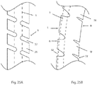
- Typical embodiments of medical device 20 have cuts 32 ( Fig. 25a and 25B ) into the sidewall of elongate member 6 to increase flexibility. Such cuts have the drawback of reducing the strength of a tubular structure and increase the chances of the device breaking.
- support spine 1 When elongate member 6 is bent during advancement through tortuous body lumens, support spine 1 is positioned against the tensile side of elongate member 6 whereby it provides support for elongate member 6 ( Fig. 25 ). By providing support to the tensile side, the support spine is able to distribute the stress of the bend or curve along a longer length of elongate member 6 than in the case of an unsupported elongate member (i.e.
- the support spine assists in distributing the load along elongate member 6 and furthermore, since an applied load must also deflect the support spine, the support spine takes some of the load directly.
- support spine 1 allows elongate member 6 to have a smoother curve than is provided by an unsupported elongate member (i.e. with no support spine) as the support spine functions as a spline (i.e. a supporting strip of material). Inclusion of support spine 1 reduces the frequency of abrupt bends along elongate member 6.
- medical device 20 include support spine 1 being comprised of a material with shape memory such as nitinol, whereby the device can be designed and manufactured to be biased towards a preconfigured shape, for example curved or straight.
- shape memory such as nitinol
- typical embodiments of medical device 20 include support spine 1 being affixed to the distal end of medical device 20 inside lumen 26 and extending proximally within the lumen, and an aperture 25 that provides for delivering fluid at the distal end of medical device 20. (There are alternative embodiments that do not have an aperture 25).
- the support spine 1 extends from the distal end within lumen distal portion 36 such that a lumen proximal portion 35 is substantially unobstructed (i.e. not obstructed by the support spine), thereby reducing and minimizing effects on fluid flow.
- a medical device as described herein comprises a flexible elongate member that defines a lumen, and an independent support spine affixed to the distal end and extending proximally therefrom within the elongate member lumen (i.e. the spine is not attached to a lumen surface or embedded in the elongate member's sidewall) whereby the support spine can support the elongate member.
- Some embodiments of the medical device further provide for delivering fluid at the device's distal end by having the flexible elongate member define apertures, at or near the device's distal end, that enable fluid communication between the lumen and the outside environment
- the support spine extends proximally from the distal end within a distal portion of the lumen such that a proximal portion of the lumen is substantially unobstructed (i.e. not obstructed by the support spine), thereby reducing and minimizing effects on fluid flow within the proximal portion of the lumen.
- some embodiments of the medical device have distal end apertures, alternative embodiments do not. Furthermore, while some embodiments of the medical device have distal end energy delivery means, alternative embodiments do not.
- some embodiments include a sensor for gathering sensory input, such as probes having temperature sensors and/or impedance sensors.
- the probes have an elongate member that is comprised of electrically conductive material(s) and/or electrically non-conductive material(s).
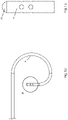
- Fig. 1 illustrates an embodiment of a medical device 20, which comprises an elongate member 6 having a proximal region 22 and a distal region 24, and an energy delivery device 15 ( Fig. 2 and, in greater detail, Fig. 5 ) associated with the distal end of device 20.
- Elongate member 6 is tubular in configuration defining at least one lumen 26 ( Fig. 2 ) extending substantially throughout its length, and is electrically conductive for conducting energy along the length of elongate member 6 to energy delivery device 15.
- elongate member 6 is a hypotube.
- elongate member 6 defines at least one aperture 25 in a wall thereof ( Fig.
- a distal aperture i.e. an aperture which is at or near the distal end of elongate member 6 or medical device 20.
- the distal aperture and the lumen defined by the elongate member combine to form a pressure transmitting lumen, whereby fluid pressure from an external environment on the aperture is transmitted through a column of fluid located in the lumen to be measured at a proximal portion of the device.
- the medical device may be operable to be coupled to a pressure sensing mechanism, such as a pressure sensor, to measure the pressure transmitted through the lumen.
- Medical device 20 further comprises a hub 9 (shown in detail in Fig. 3 ) associated with the proximal region 22 of elongate member 6.
- elongate member 6 of Fig. 1 While the embodiment of elongate member 6 of Fig. 1 is biased towards a straight configuration, as illustrated, elongate member 6 is flexible enough to bend when being advanced through a curved lumen.
- Some alternative embodiments of elongate member 6 include a curved portion (e.g. Fig. 7 ).
- Elongate member 6 and energy delivery device 15 are electrically coupled by one or more of a variety of connecting means.
- connecting means include welding (including laser welding), soldering, electrically conductive adhesives, and/or press fitting.
- Elongate member 6 is typically made from different electrically conductive materials. Examples of materials include stainless steel, copper, nickel, titanium, and alloys thereof. Some embodiments include elongate member 6 comprising a stainless steel hypotube or a nitinol hypotube.
- the Fig. 2 embodiment of a distal portion of medical device 20 comprises an insulation layer 7 disposed on top of, or around, the distal region 24 of elongate member 6.
- Insulation layer 7 extends substantially from proximal region 22 to distal region 24 of elongate member 6.
- Insulation layer 7 may be made, for example, from an electrically insulative material such as PEBAX ® (polyether block amide), PEEK (Polyether ether ketone), PTFE (Polytetrafluoroethylene), or another thermoplastic material.
- PEBAX ® polyether block amide
- PEEK Polyether ether ketone
- PTFE Polytetrafluoroethylene
- the Fig. 2 embodiment illustrates insulation layer 7 extending over a proximal portion of thermal shield 3.
- medical device 20 include elongate member 6 defining one or more aperture(s) 25, for example, as shown in Fig. 2 .
- Aperture(s) 25 facilitate fluid communication between the outside environment and lumen 26.
- medical device 20 includes a hub 9 that typically also functions as a handle for a physician when medical device 20 is used ( Figs. 1, 3 ).
- Alternative embodiments of medical device 20, such as the example of Fig. 7 include an alternate hub 9 (also shown in Fig. 17 ).
- proximal region 22 is coupled to a hub 9 (shown in detail in Fig. 3 ) which is coupled to flexible tubing 10, whereby proximal region 22 is in fluid communication with fluid connector 11.
- flexible tubing 10 is comprised of a flexible polymer, for example polyvinylchloride (PVC), or another flexible polymer, or Tygon ® .
- Connector 11 is structured to be operatively connected to a source of fluid, for example a syringe or an aspirating device, or to a pressure sensing device, for example a pressure transducer.
- Medical device 20 also includes means for electrically coupling proximal region 22 of elongate member 6 to an energy source.
- Proximal region 22 connects to hub 9.
- Insulated wire 13 is electrically coupled to proximal region 22 within hub 9.
- the proximal end of insulated wire 13 is connected to electrical connector 14 (e.g. a plug), which is electrically coupled to a source of energy, for example a generator.
- Strain relief 8 ( Figs. 1, 3 , and 7 ) provides for a transition of stiffness between proximal region 22 of elongate member 6 and hub 9, i.e. strain relief 8 prevents an abrupt change of flexibility and rigidity at the location where hub 9 is connected to elongate member 6.
- strain relief 8 is a flexible layer, for example, heat shrink, which covers and surrounds insulation layer 7.
- Fig. 4 illustrates an embodiment of support spine 1 (or support wire) that is generally straight and that is appropriate for use in medical devices 20 that are generally straight (for example, medical device 20 of Fig. 1 ).
- An energy delivery device 15 and radiopaque markers 5 are attached to support spine 1 of Fig. 4 .
- the support spine has a plurality of evenly spaced markers attached thereto.
- the lumen containing support spine 1 is lumen 26 of elongate member 6, which is typically from about 60 cm to about 120 cm in length. In some embodiments the support spine 1 (or support wire) extends for a distance of about 10 cm (or about 4 inches).
- the support spine is typically somewhat (for example, a few millimeters) longer than a distal laser-cut section of elongate member 6 ( Fig. 6 ) to provide overlap with an uncut portion of elongate member 6.
- Typical embodiments of support spine 1 have a proximal portion that is straight.
- Alternative embodiments of the support spine 1 e.g. Figs. 27A and B
- Other alternative embodiments which also facilitate contact with elongate member 6 include the support spine being comprised of a spring, for example a helical spring or a leaf spring.
- Typical embodiments of support spine 1 have a constant outer diameter.
- Alternative embodiments of the support spine 1 can have a varying or non-constant outer diameter.
- the support spine tapers proximally to facilitate contact with elongate member 6 and thereby providing an alternative electrical path to electrode 19.
- support spine 1 are comprised of one wire.
- Alternative embodiments of support spine 1 are comprised of two or more wires joined side-by-side to provide a preferential bending direction or two or more wires braided together for greater strength and flexibility.
- support spine 1 are comprised of a solid wire.
- Alternative embodiments of support spine 1 are comprised of a ribbon to provide a preferential bending plane or direction.
- support spine 1 For ease of manufacturing, typical embodiments of support spine 1 have a circular cross-section. Alternative embodiments of support spine 1 can have non-circular cross-sections, for example, D-shaped, triangular, or rectangular, which have preferential bending directions.
- Radiopaque markers 5 are used to highlight the location of important landmarks on medical device 20. Such landmarks may include the location of energy delivery device 15 or the location of any aperture(s) 25 (e.g. Fig 11 ). In general, the radiopaque markers provide the radiopacity to more readily visualize the device under fluoroscopy or other medical imaging modalities. Some embodiments of marker 5 are comprised of platinum. Furthermore, some embodiments of energy delivery device 15 include a conductive spacer 4 (see, for example, Fig. 27B ) that is comprised, for example, of platinum, whereby spacer 4 can also function as a visualization marker.
- coiled markers 5 are installed on support spine 1 with a flare 12 adjacent each end of the marker.
- Each flare 12 acts as a restraint to prevent coiled marker 5 from moving or travelling along support spine 1.
- each flare 12 is comprised of a flattened portion of support spine 1 (or flattened wire).
- one or both ends of a coiled marker could be fixed in place by laser welding or crimping.
- a coiled marker 5 is typically comprised of platinum or tungsten. In the embodiment of Fig.
- the coiled marker is proximal of the aperture 25 whereby it can help identify the location of the aperture so as to assist the physician in positioning the aperture. For example, by positioning coiled marker 5 outside (distal) of a dilator, a physician would ensure that aperture 25 is also located outside of the dilator whereby the aperture 25 could be used to deliver fluids.
- Electrode 19 includes support structure 2 and a conductive dome 16.
- support structure 2 is a metallic puck (or disk-shaped element), and in certain embodiments is comprised of tantalum.
- conductive spacer 4 is comprised of platinum.
- the electrode of such embodiments is comprised of electrically conductive material, for example, stainless steels, copper, and/or platinum.
- the electrode has a hemispherical, rounded, or domed end. In some alternative embodiments, the electrode has other configurations, for example, substantially cylindrical. The electrode is sized for creating a puncture in a tissue of a heart septum while minimizing hemodynamic instability
- intermediate conductive element 18 is covered (or surrounded) by a thermal shield 3, which in some examples is a ceramic, for example, a sapphire ceramic. In alternative embodiments, intermediate conductive element 18 is fabricated from other materials.
- the Fig. 5 embodiment of medical device 20 has a support spine 1 extending proximally of conductive spacer 4, with spine 1 including a flare 12.
- Support spine 1 provides stiffness to the flexible portion of medical device 20 while leaving lumen 26 sufficiently unobstructed for flow of fluid, such as contrast fluid for imaging purposes.
- Support spine 1 is comprised of nitinol and provides shape memory properties to the device.
- flare 12 is attached to support spine 1, for example by welding.
- flare 12 and support spine 1 are integral (i.e. support spine 1 and flare 12 comprise a unitary part), such as in the case of support spine 1 and flare 12 being produced by the machining of a single piece of cylindrical metal.
- flare 12 retains conductive spacer 4 in place.
- intermediate conductive element 18 is an extension of support spine 1.
- intermediate conductive element 18 is a separate part distinct from support spine 1, for example, a wire or rod.
- electrode 19 is typically attached to the other components of energy delivery device 15 by welding, in alternative embodiments, electrode 19 is operatively coupled to the other components of energy delivery device 15 by alternative means, for example, gluing.
- conductive spacer 4 is replaced by other energy delivery elements to facilitate electrical communication between energy delivery device 15 and elongate member 6 (e.g. Fig.27 ).
- the embodiment of Fig. 5 includes a band marker 5, while alternative embodiments include a coiled marker, for example as described hereinabove. While the above described embodiment of Fig. 5 includes metallic parts, alternative embodiments comprise corresponding parts made of non-metallic electrically conducting materials.
- notches are cut into elongate member 6, for example by laser-cutting, to increase flexibility.
- Different configurations of cuts are possible, including: c-cuts, spiral shaped cuts, interrupted spiral cuts, interlocking cuts and dove-tail cuts.
- the cuts traverse the wall thickness of elongate member 6.
- Embodiments include the distal portion of elongate member 6 having cuts ranging from about 3 cm in length to substantially the entire length of the shaft of elongate member 6, which is typically from about 60 cm to about 120 cm in length.
- medical device 20 has cuts made into the last 10 cm (i.e. the most distal 10 cm) of elongate member 6 and support spine 1 is about 10 to 11 cm in length, i.e. equivalent to or somewhat greater than the length of the portion of elongate member 6 having cuts.
- the embodiment of Fig. 6 comprises cuts into elongate member 6 that include constant pitch portion B, variable pitch portion C and dual pitch portion D. Having a smaller pitch (i.e. the cuts being closer together) increases the flexibility of elongate member 6. For example, the distal part of variable pitch portion C has a smaller pitch than the proximal part of portion C and consequently is more flexible. Having a dual pitch (i.e. two cut lines) further increases the flexibility of elongate member 6, such as is found in dual pitch portion D. In an alternative embodiment, all of sections B, C and D have dual pitches.
- a more flexible distal region 24 facilitates navigating through conduits in a patient's body, for example blood vessels, while a stiffer proximal region 22 facilitates pushability, or resistance to kinking (i.e. cross-sectional area collapse) under axial compression force. Also, a stiffer proximal region 22 improves torque response at the distal tip in response to forces applied at the proximal portion of the device.
- elongate member 6 depends on its wall thickness and/or outer diameter.
- Alternative embodiments of elongate member 6 have different wall thickness dimensions and/or different outer diameters along the length of elongate member 6 to vary flexibility along elongate member 6 (with each such embodiment having constant thickness and diameter dimensions, respectively, along the length of elongate member 6).
- support spine 1 In some embodiments of medical device 20, in which elongate member 6 is normally biased to be straight, the shape memory properties and stiffness of support spine 1 allows medical device 20 to behave similarly to a guide-wire and to revert to a straight configuration after being bent. Such embodiments of support spine 1 also provide stiffness to balance the flexibility created by any cuts made into elongate member 6.
- the outer diameter of elongate member 6 ranges from about 0.010" (0.025 mm) to about 0.050" (0.13 mm). In some embodiments, the inner diameter of elongate member 6 ranges from about 0.005" (0.013 mm) to about 0.030" (0.076 mm), or, in some embodiments, from about 0.020" (0.051 mm) to about 0.030" (0.076 mm). Elongate member 6 is between about 60 cm and about 120 cm in length. In a specific embodiment, elongate member 6 has in an inner diameter of about 0.025 inches (0.064 cm) and an outer diameter of about 0.029 inches (0.074 cm).
- elongate member 6 has in an inner diameter of about 0.0265 inches (0.067 cm) and an outer diameter of about 0.0325 inches (0.083 cm).
- the dimensions of elongate member 6 depend on one or more factors, including the distance to the target site, the tortuosity and/or diameter of the vessel(s) to be navigated, whether or not the elongate member is exchange length, as well as any other requirements imposed by auxiliary devices to be used with elongate member 6.
- elongate member 6 may be sized to be compatible with a particular sheath and/or dilator.
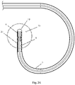
- medical device 20 include elongate member 6 comprising a distal curved portion 30 that has a distal end 28, such as the example of Fig. 7 .
- the embodiment of Fig. 7 includes a hub 9 that also functions as a handle.
- Fig. 17 is a partially cut away view of the embodiment of Fig. 7 that illustrates some details of hub 9.
- Hub 9 includes fluid connector 11 and electrical connector 14, as well as lumens communicating with the connectors.
- Distal curved portion 30 of Fig. 7 is shown in detail in Fig. 8 .
- the embodiment illustrated in Fig. 8 includes: apertures 25 for allowing fluid flow between lumen 26 and the environment outside of medical device 20; as well as electrode 19 for delivering electrical energy, such as radiofrequency electrical energy (RF), to a treatment site.
- Fig. 9 which illustrates detail A of Fig. 8 , includes enlarged views of apertures 25 and the electrode 19.
- Curved portion 30 is sufficiently flexible so that it may be substantially straightened out when it is inserted into a straight tube or vessel and may bend or curve when advanced through curved vasculature or other body lumens or when exiting the straight tube or vessel. Consequently, embodiments of medical device 20 having distal curved portion 30 may be used with a sheath and/or dilator for advancement through body lumens.
- Fig. 10 is a diagrammatic cut-away view of an embodiment of medical device 20, including a curved portion 30.
- Embodiments of medical device 20 having a distal curved portion 30 similar to that of Fig. 8 typically have a support spine 1 that includes, in an installed configuration, a curved distal end portion similar to the example of Fig. 14 .
- the embodiment of Fig. 14 also illustrates band markers 5 and energy delivery device 15.
- Fig. 16 is an illustration of the area marked "A" in Fig. 15 .
- Energy delivery device 15 of the embodiments illustrated in Figs. 15 and 16 is comprised of a conductive dome 16 and conductive spacer 4.
- support spine 1 (the support wire) is shown substantially centered within lumen 26, while in actual use (as explained hereinbelow), support spine 1 is typically not centered within lumen 26 of elongate member 6.
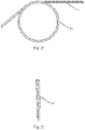
- Figs. 20 to 22 illustrate an embodiment of a support spine 1, before installation within elongate member 6, for a version of the medical device having a curved distal portion.
- Fig. 20 shows an entire support spine 1 including coiled portion 34.
- Fig. 21 is an illustration of detail A of Fig. 20 showing an enlargement of coiled portion 34
- Fig. 22 is an end view of the embodiment of Fig. 21.
- Figs. 21 and 22 illustrate that for this embodiment, support spine 1 overlaps itself in the coiled portion 34.
- Support spine 1 is elastically biased towards a curved or looped configuration prior to being inserted into lumen 26 of elongate member 6.
- the support spine 1 acts to bias a portion of medical device 20, within which coiled portion 34 of support spine 1 is located, to have a curved section, while elongate member 6 is typically biased towards a straight configuration. Therefore, when support spine 1 (of Fig. 20 ) is installed within an elongate member 6, the biasing force of support spine 1 and the biasing force of elongate member 6 act against each other, resulting in the medical device having a curved portion 30 with a curvature between that of coiled portion 34 of support spine 1 and straight elongate member 6.
- An example of a curved portion 30 of medical device 20 is shown in Fig. 8.
- Fig. 8 illustrates one possible configuration of a curved portion: alternative embodiments of medical device 20 have a curved portion with a different shape or configuration, for example, the curved portion having a different size and/or radius of curvature.
- support spine 1 is typically positioned against the inner radius side of lumen 26 through most of curved portion 30 to provide the curve.
- Fig. 18 An embodiment of curved portion 30 of medical device 20 is shown in Fig. 18 , which is a cut-away view of detail A of Fig. 17 .
- the particular embodiment of Fig. 18 in the illustrated position, includes a substantially 270 degree curve having a length dimension of about 10.5 mm ( ⁇ 50%), a lateral dimension of about 13.1 mm ( ⁇ 50%), the first 90 degrees of the curve having a radius of about 6.5 mm ( ⁇ 50%), and the last 90 degrees of the curve having a radius of about 4 mm ( ⁇ 50%).
- the curve is sized for fitting inside limited-size structures of human anatomy, for example, a left atrium.
- support spine 1 In those embodiments of medical device 20 that are substantially biased towards a straight configuration when assembled, such as the examples of Figs. 1 to 6 , it is typical for support spine 1 to be biased towards assembled straight configuration as well.
- medical device 20 both use a support spine 1 (or support wire) that is pre-shaped to provide the device with a "default" position that the device is normally biased towards and which is not permanently altered by interaction with anatomy when advanced through body lumens or other structures.
- medical device 20 is resilient (i.e. it returns to its original form after being bent or otherwise manipulated from its default shape).
- Some embodiments of medical device 20 that are straight (and which include an energy delivery device 15) facilitate forward linear advancement, that is, along a substantially straight line, and may be used for cutting and channeling through tissue, for example, CTOs (chronic total occlusions).
- Embodiments of medical device 20 that have a distal curved portion 30 may be used for cutting through other types of tissue that are more readily accessible using curved devices such as a septum of the heart in a transseptal procedure.
- curved devices such as a septum of the heart in a transseptal procedure.
- the distal end of medical device 20 emerges from a support catheter and punctures a septum, whereupon embodiments with a distal curved (or curled) portion (e.g. a 270 degree curve) facilitate performing the procedure by orientating the electrode towards the center of the curl and away from the opposite heart chamber wall after advancement through the tissue, in order to increase patient safety by reducing the risk of accidental perforation of a heart wall or other vital structure.
- a distal curved (or curled) portion e.g. a 270 degree curve
- medical device 20 e.g. a generally straight device and a straight device with a curved distal end portion
- a heat shield e.g. Fig. 2
- other embodiments do not include a heat shield (e.g. Fig. 11 ).
- Figs. 12 and 13 are illustrations of the embodiments of Figs. 8 and 9 with insulation layer 7 being removed.
- Fig. 11 shows a close-up view of detail A of Fig. 10 .
- the embodiment of Fig. 11 includes energy delivery device 15, which is comprised of conductive dome 16 and spacer 4.
- dome 16 is formed by end-welding a portion of support spine 1 that extends distally through the bore of spacer 4.
- the heat from welding support spine 1 also welds conductive dome 16 with the distal end surface of spacer 4, as well as welding a distal portion of support spine 1 to a distal portion of spacer 4 to form weld 27.
- weld 27 has a different configuration than in the example of Fig. 11 , for example, extending proximally a greater or lesser distance.
- Fig. 11 includes conductive spacer 4 being joined, i.e. electrically coupled, with elongate member 6, typically by tack welding.
- conductive spacer 4 and member 6 are joined by other methods, including electrically conductive adhesives, solder, laser welding and/or press fitting.
- dome 16 is formed by machining cylindrical stock that is integral with support spine 1, and in other alternative embodiments, an electrode is squeezed onto the end of medical device 20 to engage other portions of the device using, for example, a friction fit.
- portions of the support spine 1, spacer 4, and elongate member 6 are melted (welded) substantially concurrently to form the dome and join the parts together.
- conductive dome 16 is in direct contact with the distal end surface of elongate member 6 and support spine 1 extends proximally from conductive dome 16 to within lumen 26 of elongate member 6.
- Elongate member 6 is covered by insulation layer 7, leaving conductive dome 16 electrically exposed to define an electrode 19.
- Fig. 11 also illustrates a band marker 5 attached to support spine 1. Band marker 5 marks or highlights the position of some apertures without increasing the outer diameter of medical device 20, by being located within a lumen 26 of elongate member 6.
- Fig. 11 illustrates that elongate member 6 is in electrical communication with spacer 4 and electrode 19. When in use, electrical energy flows from elongate member 6 to electrode 19 either directly from elongate member 6 or via spacer 4.
- Fig. 19 illustrates a close-up of detail A of Fig. 18 and shows a specific embodiment of the distal end portion of medical device 20.
- Fig. 19 illustrates insulation layer 7 having an outer diameter of about 0.9 mm (0.0365 inches), elongate member 6 (e.g. a hypotube) having an outer diameter of about 0.8 mm (0.0325 inches) and an inner diameter of about 0.7 mm (0.0265 inches), and support spine 1 having an outer diameter of about 0.2 mm (0.008 inches).
- Alternative embodiments have other dimensions for these features, for example as disclosed in copending application serial number 61/781,231 , entitled "Electrosurgical Device Having a Lumen”.
- insulation layer 7 having an outer diameter of between about 0.5 mm to about 1.0 mm, or, more specifically about 0.7 to about 1.0 mm; elongate member 6 having an outer diameter of between about 0.4 mm to about 0.9 mm or, more specifically, between about 0.6 and about 0.9 mm; elongate member 6 having an inner diameter of between about 0.3 mm to about 0.8 mm or, more specifically, between about 0.5 mm to about 0.8 mm; and support spine 1 having an outer diameter of between about 0.1 mm to about 0.3 mm.
- the small diameter of support spine 1 minimizes the obstruction of lumen 26 and thereby facilitates fluid flow, and also allows the spine to be flexible whereby it may make contact with the electrically conductive inner surface of the elongate member.
- the electrode of Fig. 19 has diameter substantially the same as the insulation layer's outer diameter of between about 0.5 mm to about 1.0 mm, and of about 0.9 mm in the illustrated embodiment.
- insulation layer 7 has an outer diameter of about 0.96 mm (0.038 inches) and support spine 1 has an outer diameter of about 0.25 mm (0.010 inches), with the inner and outer diameters of elongate member 6 falling between these two values.
- support spine 1 An elongate configuration of support spine 1 is illustrated in Figs. 14 and 15 . Due to its elongate shape, support spine 1 is typically not self-supporting; rather, support spine 1 is typically floppy (i.e. loosely hanging at its proximal end).
- a proximal end or portion of support spine 1 is normally in contact (at least, electrical contact) with a wall of lumen 26, such that electrical energy from elongate member 6 can flow through support spine 1 to electrode 19, whereby support spine 1 can provide a secondary pathway for electrical energy to electrode 19.
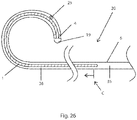
- FIG. 26 Another aspect of support spine 1 is illustrated in the example of Fig. 26 .
- Support spine 1 is drawn using hatch-marks to indicate that it is a different material than elongate member 6.
- the hatch-marks are not intended to limit support spine 1 to having cuts therein, as support spine 1 may, or may not, have cuts made therein or therethrough.
- Fig. 26 illustrates an embodiment of elongate member 6 with a distal portion having cuts made into it (although the individual cuts are not shown in the figure), starting at the point labeled with a "C".
- the support wire (or spine) extends proximally beyond point "C".
- support spine 1 is typically in contact with a wall of lumen 26, whereby electrical energy from elongate member 6 can flow through support spine 1 to energy delivery device 15, as described hereinabove.
- support spine 1 extends proximally beyond the cut portion of elongate member 6, (i.e. the proximal end of the support spine is proximal of the proximal end of the cut whereby the support spine overlaps with an uncut portion of the elongate member), whereby support spine 1 provides a backup or secondary electrical pathway in the case of a breakage or interruption in the pathway through the cut portion of elongate member 6.
- support spine 1 is connected at the distal end of the medical device 20 and extends proximally therefrom, while the proximal end of support spine 1 remains un-attached to, and independent of, elongate member 6 (or any other part of medical device 20), i.e. substantially only the distal end of support spine 1 is attached or otherwise connected to the medical device 20.
- support spine 1 extends proximally from the energy delivery device. While the embodiments of Figs. 1 to 27 show support spine 1 being joined to the center of electrode 19 of energy delivery device 15, alternative embodiments have support spine 1 attached or otherwise coupled to the device at other locations.
- an alternative embodiment comprises a closed-ended lumen with the support wire (or spine) being attached off-center.
- Another alternative embodiment comprises an open-ended lumen with the support wire being attached to a side-wall defining the lumen about the distal end of medical device 20.
- the proximal end of support spine 1 is independent of (or relative to) the side of lumen 26 (i.e. it is not fixed to the side of the lumen). This allows the proximal end of support spine 1 to be able to move longitudinally (and laterally) relative to the inner wall of the elongate member (e.g. a hypotube), which allows the distal end of medical device 20 (where the support spine 1 and elongate member 6 are joined) to bend or curve unimpeded by support spine 1. The ability of the distal end portion of medical device 20 to bend or curve facilitates advancing the device through tortuous vasculature and other body vessels.
- the elongate member e.g. a hypotube
- a difference in bend radius between the wall of elongate member 6 and support spine 1 arises from differences in the bend axis due to the wall thickness of the elongate member and the position of the support wire.
- the difference in bend radii results in different arc lengths for elongate member 6 and support spine 1.
- the support spine 1 were to be fixed at a proximal portion of medical device 20, the arc-lengths of elongate member 6 and support spine 1 would be fixed, and therefore the catheter curvature would be constrained.
- fixing the arc-lengths of elongate member 6 and support spine 1 is beneficial if such constraint of curvature of the medical device 20 is desirable (i.e. if a user desires to limit the amount of bending that is applied to a distal portion of medical device 20).
- Fig. 25A is a diagram of a portion of an embodiment of medical device 20 showing a substantially straight portion of elongate member 6 with an interrupted (or discontinuous) spiral cut 32 through its sidewall.
- Some embodiments of elongate member 6 have an interrupted spiral cut 32 comprising a cut of about 120 degrees around the circumference of elongate member 6, followed by about 30 degrees of un-cut material around the circumference.
- Alternative embodiments include a different cut pattern.
- the embodiment of Fig. 25A includes a generally straight support spine 1 (represented in broken line in the figure) within lumen 26.
- Fig. 25B illustrates the embodiment of Fig. 25A with a bend or curve.
- side "L" of elongate member 6 is in tension while side “R” is in compression.
- the U (uncut) portions of the sidewall of elongate member 6 on side L are being stretched, pulled or spread apart resulting in the spiral cuts 32 on the tensile side being larger (e.g. in length) than the cuts in Fig. 25A , where the device is shown at rest (i.e. in its straight configuration).
- the U (uncut) portions of the sidewall of elongate member 6 on side R are being compressed, pushed or squeezed together resulting in the spiral cuts 32 on the compressive side being smaller (e.g. in length) than the cuts shown in Fig. 25A .
- FIG. 25A shows support spine 1 as being positioned centrally within lumen 26
- Fig. 25B shows the support spine 1 being positioned against the tensile side of elongate member 6 whereby it provides support for elongate member 6.
- the support spine is able to distribute the stress of the bend or curve along a longer length of elongate member 6 than in the case of an unsupported elongate member (i.e.
- the support spine assists in distributing the load along elongate member 6 and furthermore, since an applied load must also deflect the support spine, the support spine takes some of the load directly.
- the support spine 1 allows elongate member 6 to have a smoother curve than is provided by an unsupported elongate member (i.e. with no support spine) as the support spine functions as a spline. Inclusion of support spine 1 reduces the frequency of abrupt bends along elongate member 6.
- a device having stiffer vessel contact surfaces is more traumatic when it is advanced through body vessels than a device with more flexible vessel contact surfaces.
- the utilization of a support spine to provide some of the stiffness allows for the medical device to have suitable rigidity or stiffness while including an elongate member that is relatively more flexible than would be the case with a device without a support spine. Utilizing a more flexible elongate member results in a more flexible "vessel contacting surface" which, in turn, reduces traumatic effects of advancement of the medical device within body vessels.
- embodiments of the devices shown in the Figures are covered with a layer of insulation such that the sharp-angled cut surfaces, e.g. as shown in Fig. 25A , are prevented from making direct contact with the vessel wall.
- An embodiment of elongate member 6 having a thinner sidewall and/or a greater number of cuts into the sidewall will have a less rigidity (or greater flexibility) than another embodiment having a thicker sidewall and/or a lesser number of cuts (or no cuts), other factors being equal.
- typical embodiments of medical device 20 include a flexible elongate member 6 that defines a lumen 26, an independent support spine 1 being affixed to the distal end of medical device 20 and extending proximally within the lumen, and apertures 25 that may provide for delivering fluid at the distal end of medical device 20.
- the support spine 1 extends from the distal end within lumen distal portion 36 such that a lumen proximal portion 35 is substantially unobstructed (i.e. not obstructed by the support spine), thereby reducing and minimizing effects on fluid flow.
- cuts are made in the most distal 10 cm of the elongate member, the support spine 1 at the distal end of lumen 26 is about 10 or 11 cm in length and elongate member is from about 60 to about 120 cm in length.
- a distally attached support spine would partially obstruct fluid flow in the distal 10 cm of the 120 cm lumen.
- a possible alternative device could have support spine 1 attached at the proximal end of lumen 26 but for it to provide support at the distal end (having cuts therein) it would have to extend the entire length of the lumen (e.g.
- the support spine 1 functions as the primary (or only) pathway for electrical energy to travel from elongate member 6 to energy delivery device 15.
- conductive spacer 4 is spaced apart from and not in contact with elongate member 6.
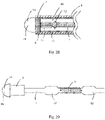
- Insulation layer 7 is a continuous layer of one material in Fig. 27A , but in alternative embodiments insulation layer 7 could be comprised of more than one type of material: for example, the portion of insulation layer 7 covering elongate member could be one (or more) type of material and the portion of insulation layer 7 distal of elongate member 6 could a different material (or materials).
- insulation layer 7 distal of elongate member 6 is comprised of electrically non-conductive material, whereby electrical energy cannot flow through insulation layer 7 to energy delivery device 15.
- the embodiment of Fig. 27A includes a spinal curve 21 to facilitate support spine 1 contacting elongate member 6.
- Some alternative embodiments have a bend.
- Other alternative embodiments of medical device 20 could have a generally straight support spine 1 (i.e. lacking spinal curve 21) or some other configuration. Whether the distal portion of support spine 1 is curved, bent, straight, or some other configuration, support spine 1 is typically sufficiently elongate and floppy to facilitate it contacting elongate member 6 at some position along its length.
- spacer 4 is typically a metallic material to facilitate welding electrode 19 to medical device 20 and securing support spine 1, in alternative embodiments, spacer 4 could be a non-metallic material and/or an electrically non-conductive material.
- thermal shield 3 comprised of non-conductive material whereby support spine 1 functions as the primary pathway for electrical energy to travel from elongate member 6 to energy delivery device 15. While thermal shield 3 is a single integral part in some embodiments (e.g. Fig. 27B ), in alternative embodiments, thermal shield 3 could be comprised of more than one part and/or material.
- the embodiment of Fig. 27B does not include a conductive spacer 4 proximal of thermal shield 3 (as seen in the example of Fig. 5 ) to enable electrical communication between elongate member 6 and electrode 19.
- Some embodiments include an energy delivery device 15 comprised of support structure 2 and electrode 19, such as the example of Fig.
- a non-conductive material restricts or impedes the electrical pathway from elongate member 6 to electrode 19 such that support spine 1 is the primary (or only) pathway of electrical conductivity between elongate member 6 and electrode 19.
- the non-conductive material could be, for example, a ceramic or a polymer.
- Medical device 20 may be used in conjunction with any source of energy suitable for delivery to a patient's body.
- Sources of energy may include, for example, generators of ultrasonic, microwave, radiofrequency or other forms of electromagnetic energy.
- energy delivery device 15 typically comprises an ultrasound transducer.
- the source of energy is a radiofrequency (RF) electrical generator, operable in the range of, for example, about 100 kHz to about 3000 kHz, designed to generate a high voltage in a short period of time. More specifically, the voltage generated by the generator may increase from about 0 Vrms to greater than about 400 Vrms in less than about 0.6 seconds.
- RF radiofrequency
- the maximum voltage generated by the generator may be between about 180V peak-to-peak and about 3000V peak-to-peak.
- the waveform generated may vary, and may include, for example, a sine-wave, or a rectangular-wave, amongst others.
- the impedance encountered during RF energy application may be very high.
- the generator may be operable to continue to maintain the voltage, even when the impedance of the tissue changes or is low. For example, energy may be delivered to a tissue within a body at a voltage that rapidly increases from 0 V to 400 V.
- Different embodiments of generators have power capabilities of 0 to 25 watts, 0 to 50 watts, or 0 to 300 watts.
- RF energy is delivered in such a way so as to result in the creation of an insulative vapor layer around the electrode, thereby resulting in an increase in impedance.
- the impedance may increase to greater than 1500 ⁇ .
- Increasing the voltage increases the intensity of fulguration, which may be desirable as it allows for an increased tissue puncture rate.
- An example of an appropriate generator for this application is a BMC RF Puncture Generator (model numbers RFP-100 and RFP-100A, Baylis Medical Company, Montreal, Canada). These generators are operable to deliver continuous RF energy at about 480 kHz.
- a grounding pad or dispersive electrode is connected to the generator for contacting or attaching to a patient's body to provide a return path for the RF energy when the generator is operated in a monopolar mode.
- Medical device 20 may be used to deliver energy to a target site within a body of a human or animal.
- the energy is RF current, and the energy functions to puncture or create a void or channel in the tissue at the target site. Further details regarding delivery of energy to a body are found in U.S.
- Patent Applications 10/347,366 (filed on January 21st, 2003 , and published as US 2004-0143261 A1 ), 10/760,749 (filed on January 21st, 2004 , and published as US 2004-0155005 A1 ), 10/666,288 (filed on September 19th, 2003 , and published as US 2004-0143262 A1 ), and 11/265,304 (filed on November 3rd, 2005 , and published as US 2006-0142756 A1 ), and U.S. Patent 7,048,733 (Application 10/666,301, filed on September 19th, 2003 ).
- an example is a method of creating a puncture in tissue, for example using embodiments of a medical device as described herein above.
- an embodiment of the method comprises: (i) introducing a medical device 20 into a body of a patient, the medical device 20 comprising an elongate member 6 having a distal region 24 and a proximal region 22 ( Fig.
- step (ii) comprises delivering fluid, for example contrast fluid, for imaging at the first desired location in the patient's body.
- Some embodiments of the method further comprise a step of (v) advancing the device to a second desired location.
- the medical device comprises at least one radiopaque marker 5 and step (v) comprises monitoring at least one of said radiopaque markers 5.
- Some embodiments of the method comprise a step (vi) of measuring pressure at the second location.
- the medical device comprise at least one radiopaque marker 5 and step (vi) is performed after confirming the position of the pressure sensing mechanism at the second location using said radiopaque markers.
- step (i) comprises introducing the device into the patient's vasculature and/or other body lumens by inserting the device 20 into a dilator 52 and a guiding sheath 50 positioned in the patient's vasculature.
- the device 20 and at least one of the dilator 52 and sheath 50 comprise a radiopaque marking and step (ii) comprises aligning the radiopaque markings to aid in positioning the device.
- step (v) comprises advancing the dilator 52 and the sheath 50 into the second location together over the spatially fixed medical device 20.
- step (v) comprises advancing the dilator, sheath and medical device all together into the second location.
- the material to be cut is tissue located on an atrial septum 56 of a heart, for example, the fossa ovalis 60 of a heart.
- the pressure measured at the first location is the blood pressure in the right atrium 54 and the pressure measured at the second location is the blood pressure in the left atrium 58.
- the method further includes delivering imaging (i.e. contrast) fluid that is visible using an imaging system in order to confirm the position of the medical device 20 at the second desired location.
- imaging i.e. contrast
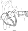
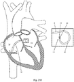
- the medical device, dilator, and sheath are introduced into the heart via the inferior vena ( Figs. 23A and 23B ).
- the heart is accessed from the superior vena cava (not shown in figures). Further details regarding superior and inferior approaches to the heart is be found in U.S. Patent Applications 13/113,326 (filed on May 23rd, 2011 , and published as US 2011-0224666 A1 ), and 11/265,304 (filed on November 3rd, 2005 , and published as US 2006-0142756 A1 ).
- the medical device comprises an elongate member having a distal region capable of adopting a curved shape to define a curved portion 30.
- a support spine with a bias towards a curved shape may be positioned within a distal portion of a lumen of the elongate member, as described herein above.
- the pre-shaped support spine causes the distal region to adopt a curved shape to direct the functional tip in a desired direction.
- the curved portion 30 is defined by a radial arc and the energy delivery device 15 is directed away from cardiac structures, as shown in Fig. 23B .
- energy delivery device 15 may be directed away from cardiac structures in order to decrease the risk of unwanted injury.
- the distal region is adapted to form a 270 degree curve.
- medical device 20 is be used to create a channel through an occluded or stenosed lumen or through other material within the body. Examples include blood vessels, stent-graft fenestrations, bile duct or airways of the respiratory tract.
- medical device 20 is positioned such that the electrode is adjacent the material to be punctured.
- Energy is delivered from a source, such as a generator, via elongate member 6, to the target site such that a void, puncture, or channel is created in or through the tissue. Further details regarding delivery of energy to create channels through occlusions or other material is found in U.S.
- Patent Application 12/926,292 filed on November 8, 201 0 , and published as US 2011-0118735 A1
- U.S. Patent Application 13/286,041 filed on October 31, 201 1 , and published as US 2012-0046657 A1
- U.S. Patent 8,048,071 issued November 1, 2011 .
- embodiments of the disclosure include a medical device comprising: a flexible elongate member that defines a lumen, and a support spine affixed to the distal end and extending proximally therefrom within the elongate member lumen (i.e. in typical embodiments the support spine is not attached to a lumen surface or embedded in the elongate member's sidewall).
- the support wire is configured to support at least a portion of the elongate member.
- Some embodiments of the medical device provide for distal end fluid delivery by defining apertures at or near the distal end that enable fluid communication between the lumen and the outside environment.
- the support spine extends from the distal end within a distal portion of the lumen such that a proximal portion of the lumen is substantially unobstructed (i.e. not obstructed by the support spine), thereby reducing and minimizing effects on fluid flow, at least within the proximal portion of the lumen.
Description
- The disclosure relates to a medical device. More specifically, it relates to an elongate medical device with a support spine. Relevant prior art is disclosed in
EP 2204134 A1 ,US 2002/111620 A1 ,EP 0667126 A1 ,WO 99/62414 A1 US 2011/118735 A1 andWO 2007/090075 A2 . - A medical device comprises a flexible elongate member that defines a lumen, and a support spine affixed to the distal end and extending proximally therefrom within the elongate member lumen (i.e. in typical embodiments the support spine is not attached to a lumen surface or embedded in the elongate member's sidewall). In some embodiments, the support wire is configured to support at least a portion of the elongate member. The medical device provides for distal end fluid delivery by defining apertures at or near the distal end that enable fluid communication between the lumen and the outside environment. Furthermore, in the invention, the support spine extends from the distal end within a distal portion of the lumen such that a proximal portion of the lumen is substantially unobstructed (i.e. not obstructed by the support spine), thereby reducing and minimizing effects on fluid flow, at least within the proximal portion of the lumen.
- In a first broad aspect, embodiments of the present invention include a medical device according to appended claim As additional features, and in some embodiments, the elongate member is generally tubular in configuration; a distal portion of its sidewall has cuts therein to increase flexibility; and the support wire minimizes the bending stress on any one cut by supporting the wall of the elongate member and distributing the bending stress along the elongate member i.e. the spine can act as a bridge across the cuts to distribute the bending stress along the elongate member.
- As a further feature of the first broad aspect according to the invention, the medical device further comprises an energy delivery device at the distal end of the elongate member that is operable to be electrically coupled to an energy source. In some such embodiments, energy can flow through the wall of the elongate member to the energy delivery device, leaving the lumen sufficiently open for functioning as a conduit for fluid flow. In certain embodiments, the wall is comprised of an electrically conductive material and the energy is electrical energy, for example in the radiofrequency range.
- In a second broad aspect, examples include a medical device comprising: an elongate member configured for traversing body lumens, the elongate member defining a lumen; and a support spine having a distal end coupled to a distal end of the medical device and extending proximally therefrom wherein a proximal end of the support spine is not coupled to the elongate member, the support spine being thereby configured to support a tensile side of the elongate member during bending. In some embodiments, the elongate member is generally tubular in configuration and a distal portion of its sidewall has cuts therein to increase flexibility. The cuts may be partially or completely through the sidewall. The support wire minimizes the bending stress on any one cut by supporting the wall of the elongate member to thereby distribute the bending stress along the length of the elongate member.
- As a feature of the second broad aspect, in some embodiments of the medical device, the lumen is in fluid communication with at least one aperture at or near a distal end of the elongate member.
- As another feature of the second broad aspect, in some embodiments of the medical device, an energy delivery device at the distal end of the elongate member is operable to be in communication with an energy source. In certain embodiments energy flows through the wall of the elongate member, whereby the lumen is left sufficiently open to function as a conduit for fluid flow. In certain embodiments, the wall is comprised of an electrically conductive material and the energy is electrical energy.
- As another feature of the second broad aspect, in some embodiments of the medical device, the support wire/spine has shape memory.
- As a further feature of the second broad aspect, in some embodiments of the medical device, a portion of the elongate member defines a curve. Alternative embodiments of the second broad aspect include the elongate member being substantially straight (i.e. not having a substantially curved portion).
- In accordance with a third broad aspect, a method of surgery is described, which does not form part of the invention. In some embodiments, the method comprises: (i) introducing a medical device into a body of a patient, the medical device comprising an elongate member having a distal region and a proximal region, an energy delivery device proximate to the distal region capable of cutting material and a lumen and apertures operable to be in communication with a pressure sensing mechanism for determining pressure in the body proximate to the distal region; (ii) positioning the energy delivery device at a first desired location in the patient's body substantially adjacent material to be cut; (iii) delivering energy using the energy delivery device to cut said material; and (iv) measuring pressure in the body using the pressure sensing mechanism in order to determine the position of the medical device at least one of before and after step (iii). In some embodiments of this aspect, step (ii) comprises delivering fluid for imaging at the first desired location in the patient's body.
- Some embodiments of the method further comprise a step of (v) advancing the device to a second desired location. In certain embodiments of this aspect, the medical device comprises at least one radiopaque marker and step (v) comprises monitoring at least one of said radiopaque markers before, during or after advancement. Some embodiments of the method comprise a further step of: (vi) measuring pressure at the second location to confirm the position of the medical device at the second location. In certain embodiments, the medical device comprises at least one radiopaque marker and step (vi) is performed after confirming the position of at least a portion of the pressure sensing mechanism (e.g. an aperture of the medical device) at the second location using said radiopaque markers.
- In some embodiments of this method aspect, step (i) comprises introducing the device into the patient's vasculature and/or other body lumens. The step of introducing the device into the patient's vasculature typically comprises inserting the device into a dilator and a guiding sheath positioned in the patient's vasculature. In certain embodiments, the device and at least one of the dilator and sheath comprise a radiopaque marker and step (ii) comprises aligning the radiopaque markers of the devices to aid in positioning the devices. For certain alternative embodiments of the method, step (v) comprises advancing the dilator and the sheath into the second location together over the spatially fixed medical device. In other alternative embodiments, step (v) comprises advancing the dilator, sheath and medical device all together into the second location.
- In accordance with the method aspect, in certain embodiments, the material to be cut is tissue located on an atrial septum of a heart. In some embodiments, the region of tissue is the fossa ovalis of a heart. In such embodiments, the pressure measured at the second location is the blood pressure in the left atrium of the heart.
- In some alternative embodiments, the method further includes delivering contrast (imaging) fluid that is visible using an imaging system in order to confirm the position of the medical device at the second desired location.
- Certain embodiments of the method include the elongate member having a distal region capable of adopting a curved shape. In some such embodiments, after the medical device tip advances through a material or out the end of the dilator, the pre-shaped support spine biases the distal region to adopt a curved shape whereby the functional tip is directed in a desired direction. In some embodiments, the curved shape is defined by a radial arc and the functional tip is directed away from cardiac structures, for example, order to decrease the risk of unwanted injury. As an example, the distal region is configured to form a 270 degree curve.
- In order that the invention may be readily understood, embodiments of the invention are illustrated by way of examples in the accompanying drawings, in which:
-
Fig. 1 is an embodiment of a medical device with a generally straight elongate member; -
Fig. 2 is an illustration of detail A ofFig 1 ; -
Fig. 3 is an illustration of detail B ofFig, 1 ; -
Fig. 4 is an illustration of a spine wire that is biased to be straight and an attached distal region energy delivery device; -
Fig. 5 is an illustration of detail A ofFig 4 ; -
Fig. 6 is an illustration of an elongate member with cuts therein; -
Fig. 7 is an illustration of an embodiment of a medical device with a curved end portion and a handle; -
Fig. 8 an illustration of detail A ofFig. 7 ; -
Fig. 9 an illustration of detail A ofFig. 8 ; -
Fig. 10 is a cut-away view of the embodiment ofFig. 8 ; -
Fig. 11 an illustration of detail A ofFig. 10 ; -
Fig. 12 is an illustration the embodiment ofFig. 8 with no external insulation layer; -
Fig. 13 is an illustration of detail A ofFig. 12 ; -
Fig. 14 is an illustration of the installed configuration of the core or support spine assembly of the embodiment ofFig. 10 ; -
Fig. 15 is a cut-away view of the embodiment ofFig. 14 ; -
Fig. 16 is an illustration of detail A ofFig. 15 ; -
Fig. 17 is a partial cut-away view of the embodiment ofFig. 7 ; -
Fig. 18 is a cut-away view of detail A ofFig. 17 ; -
Fig. 19 is an illustration of detail A ofFig. 18 ; -
Fig. 20 is an illustration of an embodiment of a support spine for a version of the medical device with a distal curve, before the spine is installed; -
Fig. 21 is an illustration of detail A ofFig. 20 ; -
Fig. 22 is an end view of the embodiment ofFig. 21 ; -
Figs. 23A and23B illustrate the before and after stages of a transseptal method; -
Fig. 24 is cross section view of a curved embodiment with a support spine; -
Figs. 25A and 25B are diagrams of a portion of an elongate member embodiment with a discontinuous spiral cut therein and a support wire; -
Fig. 26 is a diagram showing a lumen distal portion containing a support spine and a proximal lumen portion that lacks the support spine; -
Figs. 27A and 27B are embodiments with electrically conductive spines; and -
Figs. 28 and 29 are embodiments with coiled markers. - The present inventors have conceived and reduced to practice a novel and inventive medical device for creating punctures or perforations in tissues. Embodiments of the medical device include features allowing for transfer of fluids through the device, while providing for internal support of the device, particularly when the device is bent or curved.
- In typical embodiments of
medical device 20,support spine 1 is connected to other features ofdevice 20 at the distal end of the medical device and the proximal end ofsupport spine 1 remains un-attached to, and independent of, elongate member 6 (or any other part of medical device 20), i.e. substantially only the distal end ofsupport spine 1 is attached or otherwise connected to themedical device 20. This allows the proximal end ofsupport spine 1 to be able to move longitudinally (and laterally) relative to the inner wall of the elongate member (e.g. a hypotube), which allows the distal end of medical device 20 (where thesupport spine 1 and elongatemember 6 are joined) to bend or curve unimpeded bysupport spine 1. The ability of the distal end portion ofmedical device 20 to bend or curve facilitates advancing the device through tortuous vasculature and other body vessels. - Furthermore, a difference in bend radius between the wall of
elongate member 6 andsupport spine 1 arises from differences in the bend axis due to the wall thickness of the elongate member and the position of the support wire. When themedical device 20 device is bent about its distal portion, the difference in bend radii results in different arc lengths forelongate member 6 andsupport spine 1. If the proximal end ofsupport spine 1 were to be fixed at a proximal portion ofmedical device 20, the relative arc-lengths ofelongate member 6 andsupport spine 1 would be fixed, and therefore the catheter curvature would be constrained bysupport spine 1. - Typical embodiments of
medical device 20 have cuts 32 (Fig. 25a and 25B ) into the sidewall ofelongate member 6 to increase flexibility. Such cuts have the drawback of reducing the strength of a tubular structure and increase the chances of the device breaking. Whenelongate member 6 is bent during advancement through tortuous body lumens,support spine 1 is positioned against the tensile side ofelongate member 6 whereby it provides support for elongate member 6 (Fig. 25 ). By providing support to the tensile side, the support spine is able to distribute the stress of the bend or curve along a longer length ofelongate member 6 than in the case of an unsupported elongate member (i.e. that does not have a spine), and consequently the stress of the bend is spread amongstmore cuts 32 and uncut (U) portions of the sidewall, resulting in reduced risk of elongate member being damaged (e.g. breaking at one isolated cut) by the stress forces of the bend or curve. Thus, the support spine, as shown inFig. 25B , assists in distributing the load alongelongate member 6 and furthermore, since an applied load must also deflect the support spine, the support spine takes some of the load directly. - Also,
support spine 1 allowselongate member 6 to have a smoother curve than is provided by an unsupported elongate member (i.e. with no support spine) as the support spine functions as a spline (i.e. a supporting strip of material). Inclusion ofsupport spine 1 reduces the frequency of abrupt bends alongelongate member 6. - Some embodiments of
medical device 20 includesupport spine 1 being comprised of a material with shape memory such as nitinol, whereby the device can be designed and manufactured to be biased towards a preconfigured shape, for example curved or straight. - As shown, for example, in
Figure 26 , typical embodiments ofmedical device 20 includesupport spine 1 being affixed to the distal end ofmedical device 20 insidelumen 26 and extending proximally within the lumen, and anaperture 25 that provides for delivering fluid at the distal end ofmedical device 20. (There are alternative embodiments that do not have an aperture 25). For typical embodiments, thesupport spine 1 extends from the distal end within lumendistal portion 36 such that a lumenproximal portion 35 is substantially unobstructed (i.e. not obstructed by the support spine), thereby reducing and minimizing effects on fluid flow. - With specific reference now to the drawings in detail, it is stressed that the particulars shown are by way of example and for purposes of illustrative discussion of certain embodiments of the present invention only. Before explaining at least one embodiment of the invention in detail, it is to be understood that the invention is not limited in its application to the details of construction and the arrangement of the components set forth in the following description or illustrated in the drawings. The invention is capable of other embodiments or of being practiced or carried out in various ways. Also, it is to be understood that the phraseology and terminology employed herein is for the purpose of description and should not be regarded as limiting.
- A medical device as described herein comprises a flexible elongate member that defines a lumen, and an independent support spine affixed to the distal end and extending proximally therefrom within the elongate member lumen (i.e. the spine is not attached to a lumen surface or embedded in the elongate member's sidewall) whereby the support spine can support the elongate member. Some embodiments of the medical device further provide for delivering fluid at the device's distal end by having the flexible elongate member define apertures, at or near the device's distal end, that enable fluid communication between the lumen and the outside environment In some such embodiments, the support spine extends proximally from the distal end within a distal portion of the lumen such that a proximal portion of the lumen is substantially unobstructed (i.e. not obstructed by the support spine), thereby reducing and minimizing effects on fluid flow within the proximal portion of the lumen.
- While some embodiments of the medical device have distal end apertures, alternative embodiments do not. Furthermore, while some embodiments of the medical device have distal end energy delivery means, alternative embodiments do not. For example, some embodiments include a sensor for gathering sensory input, such as probes having temperature sensors and/or impedance sensors. In some such embodiments, the probes have an elongate member that is comprised of electrically conductive material(s) and/or electrically non-conductive material(s).
-
Fig. 1 illustrates an embodiment of amedical device 20, which comprises anelongate member 6 having aproximal region 22 and adistal region 24, and an energy delivery device 15 (Fig. 2 and, in greater detail,Fig. 5 ) associated with the distal end ofdevice 20.Elongate member 6 is tubular in configuration defining at least one lumen 26 (Fig. 2 ) extending substantially throughout its length, and is electrically conductive for conducting energy along the length ofelongate member 6 toenergy delivery device 15. In some embodiments,elongate member 6 is a hypotube. In addition, in typical embodiments,elongate member 6 defines at least oneaperture 25 in a wall thereof (Fig. 2 ), which in typical embodiments is a distal aperture, i.e. an aperture which is at or near the distal end ofelongate member 6 ormedical device 20. The distal aperture and the lumen defined by the elongate member combine to form a pressure transmitting lumen, whereby fluid pressure from an external environment on the aperture is transmitted through a column of fluid located in the lumen to be measured at a proximal portion of the device. For example, the medical device may be operable to be coupled to a pressure sensing mechanism, such as a pressure sensor, to measure the pressure transmitted through the lumen.Medical device 20 further comprises a hub 9 (shown in detail inFig. 3 ) associated with theproximal region 22 ofelongate member 6. While the embodiment ofelongate member 6 ofFig. 1 is biased towards a straight configuration, as illustrated,elongate member 6 is flexible enough to bend when being advanced through a curved lumen. Some alternative embodiments ofelongate member 6 include a curved portion (e.g.Fig. 7 ). -
Elongate member 6 and energy delivery device 15 (seeFig. 5 as well) are electrically coupled by one or more of a variety of connecting means. For example, connecting means include welding (including laser welding), soldering, electrically conductive adhesives, and/or press fitting. -
Elongate member 6 is typically made from different electrically conductive materials. Examples of materials include stainless steel, copper, nickel, titanium, and alloys thereof. Some embodiments includeelongate member 6 comprising a stainless steel hypotube or a nitinol hypotube. - The
Fig. 2 embodiment of a distal portion ofmedical device 20 comprises aninsulation layer 7 disposed on top of, or around, thedistal region 24 ofelongate member 6.Insulation layer 7 extends substantially fromproximal region 22 todistal region 24 ofelongate member 6.Insulation layer 7 may be made, for example, from an electrically insulative material such as PEBAX® (polyether block amide), PEEK (Polyether ether ketone), PTFE (Polytetrafluoroethylene), or another thermoplastic material. TheFig. 2 embodiment illustratesinsulation layer 7 extending over a proximal portion ofthermal shield 3. - Some embodiments of
medical device 20 includeelongate member 6 defining one or more aperture(s) 25, for example, as shown inFig. 2 . Aperture(s) 25 facilitate fluid communication between the outside environment andlumen 26. - Some embodiments of
medical device 20 include ahub 9 that typically also functions as a handle for a physician whenmedical device 20 is used (Figs. 1, 3 ). Alternative embodiments ofmedical device 20, such as the example ofFig. 7 , include an alternate hub 9 (also shown inFig. 17 ). - In some embodiments, for example the embodiments of
Figs. 1 and 3 ,proximal region 22 is coupled to a hub 9 (shown in detail inFig. 3 ) which is coupled toflexible tubing 10, wherebyproximal region 22 is in fluid communication withfluid connector 11. In certain embodiments,flexible tubing 10 is comprised of a flexible polymer, for example polyvinylchloride (PVC), or another flexible polymer, or Tygon®.Connector 11 is structured to be operatively connected to a source of fluid, for example a syringe or an aspirating device, or to a pressure sensing device, for example a pressure transducer. - Medical device 20 (
Figs. 1 and 3 ) also includes means for electrically couplingproximal region 22 ofelongate member 6 to an energy source.Proximal region 22 connects tohub 9.Insulated wire 13 is electrically coupled toproximal region 22 withinhub 9. The proximal end ofinsulated wire 13 is connected to electrical connector 14 (e.g. a plug), which is electrically coupled to a source of energy, for example a generator. - Strain relief 8 (
Figs. 1, 3 , and7 ) provides for a transition of stiffness betweenproximal region 22 ofelongate member 6 andhub 9, i.e.strain relief 8 prevents an abrupt change of flexibility and rigidity at the location wherehub 9 is connected to elongatemember 6. In certain embodiments,strain relief 8 is a flexible layer, for example, heat shrink, which covers and surroundsinsulation layer 7. Some alternative embodiments do not includestrain relief 8. -
Fig. 4 illustrates an embodiment of support spine 1 (or support wire) that is generally straight and that is appropriate for use inmedical devices 20 that are generally straight (for example,medical device 20 ofFig. 1 ). Anenergy delivery device 15 andradiopaque markers 5 are attached to supportspine 1 ofFig. 4 . The support spine has a plurality of evenly spaced markers attached thereto. - In general, there is no minimum spine length and the maximum support spine length is limited by the length of the lumen containing the spine. The lumen containing
support spine 1 is lumen 26 ofelongate member 6, which is typically from about 60 cm to about 120 cm in length. In some embodiments the support spine 1 (or support wire) extends for a distance of about 10 cm (or about 4 inches). Various dimensions and specific limitations will be presently described. These specific dimensions and limitations are not mere design choices that would be obvious to one of skill in the art but are rather particularly advantageous for the embodiments of devices and methods described herein. For example, the support spine is typically somewhat (for example, a few millimeters) longer than a distal laser-cut section of elongate member 6 (Fig. 6 ) to provide overlap with an uncut portion ofelongate member 6. - Typical embodiments of
support spine 1 have a proximal portion that is straight. Alternative embodiments of the support spine 1 (e.g.Figs. 27A and B ) have a curved proximal end to facilitate the proximal tip of the wire contacting the side of lumen 26 (i.e. an inner wall of elongate member 6) for electrical connection (i.e. electrical communication). Other alternative embodiments which also facilitate contact withelongate member 6 include the support spine being comprised of a spring, for example a helical spring or a leaf spring. - Typical embodiments of
support spine 1 have a constant outer diameter. Alternative embodiments of thesupport spine 1 can have a varying or non-constant outer diameter. In some embodiments, the support spine tapers proximally to facilitate contact withelongate member 6 and thereby providing an alternative electrical path toelectrode 19. - For ease of manufacturing, typical embodiments of
support spine 1 are comprised of one wire. Alternative embodiments ofsupport spine 1 are comprised of two or more wires joined side-by-side to provide a preferential bending direction or two or more wires braided together for greater strength and flexibility. - For ease of manufacturing, typical embodiments of
support spine 1 are comprised of a solid wire. Alternative embodiments ofsupport spine 1 are comprised of a ribbon to provide a preferential bending plane or direction. - For ease of manufacturing, typical embodiments of
support spine 1 have a circular cross-section. Alternative embodiments ofsupport spine 1 can have non-circular cross-sections, for example, D-shaped, triangular, or rectangular, which have preferential bending directions. -
Radiopaque markers 5 are used to highlight the location of important landmarks onmedical device 20. Such landmarks may include the location ofenergy delivery device 15 or the location of any aperture(s) 25 (e.g.Fig 11 ). In general, the radiopaque markers provide the radiopacity to more readily visualize the device under fluoroscopy or other medical imaging modalities. Some embodiments ofmarker 5 are comprised of platinum. Furthermore, some embodiments ofenergy delivery device 15 include a conductive spacer 4 (see, for example,Fig. 27B ) that is comprised, for example, of platinum, wherebyspacer 4 can also function as a visualization marker. - Some alternative embodiments have a spiral or a coiled marker 5 (
Figs. 28 and 29 ) rather than band or ring markers, to provide greater flexibility. In the embodiments ofFigs. 28 and 29 , coiledmarkers 5 are installed onsupport spine 1 with aflare 12 adjacent each end of the marker. Eachflare 12 acts as a restraint to prevent coiledmarker 5 from moving or travelling alongsupport spine 1. In the embodiment ofFig. 29 , eachflare 12 is comprised of a flattened portion of support spine 1 (or flattened wire). In other alternative embodiments, one or both ends of a coiled marker could be fixed in place by laser welding or crimping. A coiledmarker 5 is typically comprised of platinum or tungsten. In the embodiment ofFig. 28 , the coiled marker is proximal of theaperture 25 whereby it can help identify the location of the aperture so as to assist the physician in positioning the aperture. For example, by positioning coiledmarker 5 outside (distal) of a dilator, a physician would ensure thataperture 25 is also located outside of the dilator whereby theaperture 25 could be used to deliver fluids. - Some embodiments of
energy delivery device 15, for example the embodiment ofFig. 5 , are comprised of anelectrode 19 which is attached to and in electrical communication with an intermediateconductive element 18, with intermediateconductive element 18 being attached and in electrical communication withconductive spacer 4.Electrode 19 includessupport structure 2 and aconductive dome 16. In the embodiment ofFig. 5 ,support structure 2 is a metallic puck (or disk-shaped element), and in certain embodiments is comprised of tantalum. In certain embodiments,conductive spacer 4 is comprised of platinum. The electrode of such embodiments is comprised of electrically conductive material, for example, stainless steels, copper, and/or platinum. In some embodiments, the electrode has a hemispherical, rounded, or domed end. In some alternative embodiments, the electrode has other configurations, for example, substantially cylindrical. The electrode is sized for creating a puncture in a tissue of a heart septum while minimizing hemodynamic instability - In some embodiments, intermediate
conductive element 18 is covered (or surrounded) by athermal shield 3, which in some examples is a ceramic, for example, a sapphire ceramic. In alternative embodiments, intermediateconductive element 18 is fabricated from other materials. - The
Fig. 5 embodiment ofmedical device 20 has asupport spine 1 extending proximally ofconductive spacer 4, withspine 1 including aflare 12.Support spine 1 provides stiffness to the flexible portion ofmedical device 20 while leavinglumen 26 sufficiently unobstructed for flow of fluid, such as contrast fluid for imaging purposes. In someembodiments Support spine 1 is comprised of nitinol and provides shape memory properties to the device. - In some embodiments, flare 12 is attached to support
spine 1, for example by welding. In alternative embodiments flare 12 andsupport spine 1 are integral (i.e.support spine 1 and flare 12 comprise a unitary part), such as in the case ofsupport spine 1 and flare 12 being produced by the machining of a single piece of cylindrical metal. In some embodiments, flare 12 retainsconductive spacer 4 in place. In some embodiments, intermediateconductive element 18 is an extension ofsupport spine 1. In alternative embodiments, intermediateconductive element 18 is a separate part distinct fromsupport spine 1, for example, a wire or rod. - While
electrode 19 is typically attached to the other components ofenergy delivery device 15 by welding, in alternative embodiments,electrode 19 is operatively coupled to the other components ofenergy delivery device 15 by alternative means, for example, gluing. In alternative embodiments,conductive spacer 4 is replaced by other energy delivery elements to facilitate electrical communication betweenenergy delivery device 15 and elongate member 6 (e.g.Fig.27 ). The embodiment ofFig. 5 includes aband marker 5, while alternative embodiments include a coiled marker, for example as described hereinabove. While the above described embodiment ofFig. 5 includes metallic parts, alternative embodiments comprise corresponding parts made of non-metallic electrically conducting materials. - In some embodiments, notches are cut into
elongate member 6, for example by laser-cutting, to increase flexibility. Different configurations of cuts are possible, including: c-cuts, spiral shaped cuts, interrupted spiral cuts, interlocking cuts and dove-tail cuts. In some embodiments, the cuts traverse the wall thickness ofelongate member 6. Embodiments include the distal portion ofelongate member 6 having cuts ranging from about 3 cm in length to substantially the entire length of the shaft ofelongate member 6, which is typically from about 60 cm to about 120 cm in length. In certain embodiments,medical device 20 has cuts made into the last 10 cm (i.e. the most distal 10 cm) ofelongate member 6 andsupport spine 1 is about 10 to 11 cm in length, i.e. equivalent to or somewhat greater than the length of the portion ofelongate member 6 having cuts. - The embodiment of
Fig. 6 comprises cuts intoelongate member 6 that include constant pitch portion B, variable pitch portion C and dual pitch portion D. Having a smaller pitch (i.e. the cuts being closer together) increases the flexibility ofelongate member 6. For example, the distal part of variable pitch portion C has a smaller pitch than the proximal part of portion C and consequently is more flexible. Having a dual pitch (i.e. two cut lines) further increases the flexibility ofelongate member 6, such as is found in dual pitch portion D. In an alternative embodiment, all of sections B, C and D have dual pitches. - A more flexible
distal region 24 facilitates navigating through conduits in a patient's body, for example blood vessels, while a stifferproximal region 22 facilitates pushability, or resistance to kinking (i.e. cross-sectional area collapse) under axial compression force. Also, a stifferproximal region 22 improves torque response at the distal tip in response to forces applied at the proximal portion of the device. - The flexibility of an embodiment of
elongate member 6 depends on its wall thickness and/or outer diameter. Alternative embodiments ofelongate member 6 have different wall thickness dimensions and/or different outer diameters along the length ofelongate member 6 to vary flexibility along elongate member 6 (with each such embodiment having constant thickness and diameter dimensions, respectively, along the length of elongate member 6). - In some embodiments of
medical device 20, in which elongatemember 6 is normally biased to be straight, the shape memory properties and stiffness ofsupport spine 1 allowsmedical device 20 to behave similarly to a guide-wire and to revert to a straight configuration after being bent. Such embodiments ofsupport spine 1 also provide stiffness to balance the flexibility created by any cuts made intoelongate member 6. - In some embodiments of the
medical device 20, the outer diameter ofelongate member 6 ranges from about 0.010" (0.025 mm) to about 0.050" (0.13 mm). In some embodiments, the inner diameter ofelongate member 6 ranges from about 0.005" (0.013 mm) to about 0.030" (0.076 mm), or, in some embodiments, from about 0.020" (0.051 mm) to about 0.030" (0.076 mm).Elongate member 6 is between about 60 cm and about 120 cm in length. In a specific embodiment,elongate member 6 has in an inner diameter of about 0.025 inches (0.064 cm) and an outer diameter of about 0.029 inches (0.074 cm). In another specific embodiment,elongate member 6 has in an inner diameter of about 0.0265 inches (0.067 cm) and an outer diameter of about 0.0325 inches (0.083 cm). The dimensions ofelongate member 6 depend on one or more factors, including the distance to the target site, the tortuosity and/or diameter of the vessel(s) to be navigated, whether or not the elongate member is exchange length, as well as any other requirements imposed by auxiliary devices to be used withelongate member 6. For example,elongate member 6 may be sized to be compatible with a particular sheath and/or dilator. - Some embodiments of
medical device 20 includeelongate member 6 comprising a distalcurved portion 30 that has adistal end 28, such as the example ofFig. 7 . The embodiment ofFig. 7 includes ahub 9 that also functions as a handle. -
Fig. 17 is a partially cut away view of the embodiment ofFig. 7 that illustrates some details ofhub 9.Hub 9 includesfluid connector 11 andelectrical connector 14, as well as lumens communicating with the connectors. - Distal
curved portion 30 ofFig. 7 is shown in detail inFig. 8 . The embodiment illustrated inFig. 8 includes:apertures 25 for allowing fluid flow betweenlumen 26 and the environment outside ofmedical device 20; as well aselectrode 19 for delivering electrical energy, such as radiofrequency electrical energy (RF), to a treatment site.Fig. 9 , which illustrates detail A ofFig. 8 , includes enlarged views ofapertures 25 and theelectrode 19.Curved portion 30 is sufficiently flexible so that it may be substantially straightened out when it is inserted into a straight tube or vessel and may bend or curve when advanced through curved vasculature or other body lumens or when exiting the straight tube or vessel. Consequently, embodiments ofmedical device 20 having distalcurved portion 30 may be used with a sheath and/or dilator for advancement through body lumens. -
Fig. 10 is a diagrammatic cut-away view of an embodiment ofmedical device 20, including acurved portion 30. - Embodiments of
medical device 20 having a distalcurved portion 30 similar to that ofFig. 8 typically have asupport spine 1 that includes, in an installed configuration, a curved distal end portion similar to the example ofFig. 14 . The embodiment ofFig. 14 also illustratesband markers 5 andenergy delivery device 15.Fig. 15 in a cut-away view of the embodiment ofsupport spine 1 ofFig. 14. Fig. 16 is an illustration of the area marked "A" inFig. 15 .Energy delivery device 15 of the embodiments illustrated inFigs. 15 and 16 is comprised of aconductive dome 16 andconductive spacer 4. - For illustrative purposes, such as the example shown in
Fig. 10 , support spine 1 (the support wire) is shown substantially centered withinlumen 26, while in actual use (as explained hereinbelow),support spine 1 is typically not centered withinlumen 26 ofelongate member 6. -
Figs. 20 to 22 illustrate an embodiment of asupport spine 1, before installation withinelongate member 6, for a version of the medical device having a curved distal portion.Fig. 20 shows anentire support spine 1 including coiledportion 34.Fig. 21 is an illustration of detail A ofFig. 20 showing an enlargement of coiledportion 34, andFig. 22 is an end view of the embodiment ofFig. 21. Figs. 21 and 22 illustrate that for this embodiment,support spine 1 overlaps itself in the coiledportion 34.Support spine 1 is elastically biased towards a curved or looped configuration prior to being inserted intolumen 26 ofelongate member 6. - The
support spine 1 acts to bias a portion ofmedical device 20, within which coiledportion 34 ofsupport spine 1 is located, to have a curved section, whileelongate member 6 is typically biased towards a straight configuration. Therefore, when support spine 1 (ofFig. 20 ) is installed within anelongate member 6, the biasing force ofsupport spine 1 and the biasing force ofelongate member 6 act against each other, resulting in the medical device having acurved portion 30 with a curvature between that of coiledportion 34 ofsupport spine 1 and straightelongate member 6. An example of acurved portion 30 ofmedical device 20 is shown inFig. 8. Fig. 8 illustrates one possible configuration of a curved portion: alternative embodiments ofmedical device 20 have a curved portion with a different shape or configuration, for example, the curved portion having a different size and/or radius of curvature. - In an assembled
medical device 20 with a curved portion 30 (e.g.Fig. 8 ),support spine 1 is typically positioned against the inner radius side oflumen 26 through most ofcurved portion 30 to provide the curve. - An embodiment of
curved portion 30 ofmedical device 20 is shown inFig. 18 , which is a cut-away view of detail A ofFig. 17 . The particular embodiment ofFig. 18 , in the illustrated position, includes a substantially 270 degree curve having a length dimension of about 10.5 mm (±50%), a lateral dimension of about 13.1 mm (±50%), the first 90 degrees of the curve having a radius of about 6.5 mm (±50%), and the last 90 degrees of the curve having a radius of about 4 mm (±50%). The curve is sized for fitting inside limited-size structures of human anatomy, for example, a left atrium. - In those embodiments of
medical device 20 that are substantially biased towards a straight configuration when assembled, such as the examples ofFigs. 1 to 6 , it is typical forsupport spine 1 to be biased towards assembled straight configuration as well. - The two above mentioned embodiments of medical device 20 (generally straight and straight with a curved distal end portion), both use a support spine 1 (or support wire) that is pre-shaped to provide the device with a "default" position that the device is normally biased towards and which is not permanently altered by interaction with anatomy when advanced through body lumens or other structures. In other words,
medical device 20 is resilient (i.e. it returns to its original form after being bent or otherwise manipulated from its default shape). Some embodiments ofmedical device 20 that are straight (and which include an energy delivery device 15) facilitate forward linear advancement, that is, along a substantially straight line, and may be used for cutting and channeling through tissue, for example, CTOs (chronic total occlusions). Embodiments ofmedical device 20 that have a distal curved portion 30 (and which also include an energy delivery device 15) may be used for cutting through other types of tissue that are more readily accessible using curved devices such as a septum of the heart in a transseptal procedure. Typically, in performing a transseptal procedure, the distal end ofmedical device 20 emerges from a support catheter and punctures a septum, whereupon embodiments with a distal curved (or curled) portion (e.g. a 270 degree curve) facilitate performing the procedure by orientating the electrode towards the center of the curl and away from the opposite heart chamber wall after advancement through the tissue, in order to increase patient safety by reducing the risk of accidental perforation of a heart wall or other vital structure. - While specific embodiments and uses are disclosed herein, all of the above described embodiments of medical device 20 (e.g. a generally straight device and a straight device with a curved distal end portion) can be used, for example, in applications involving channeling through tissue such as CTOs, or for general tissue puncture such as transseptal procedures. Furthermore, some embodiments include a heat shield (e.g.
Fig. 2 ) and other embodiments do not include a heat shield (e.g.Fig. 11 ). -
Figs. 12 and 13 are illustrations of the embodiments ofFigs. 8 and 9 withinsulation layer 7 being removed. -
Fig. 11 shows a close-up view of detail A ofFig. 10 . The embodiment ofFig. 11 includesenergy delivery device 15, which is comprised ofconductive dome 16 andspacer 4. In some embodiments,dome 16 is formed by end-welding a portion ofsupport spine 1 that extends distally through the bore ofspacer 4. The heat from weldingsupport spine 1 also weldsconductive dome 16 with the distal end surface ofspacer 4, as well as welding a distal portion ofsupport spine 1 to a distal portion ofspacer 4 to formweld 27. In alternative embodiments,weld 27 has a different configuration than in the example ofFig. 11 , for example, extending proximally a greater or lesser distance. - The example of
Fig. 11 includesconductive spacer 4 being joined, i.e. electrically coupled, withelongate member 6, typically by tack welding. In alternative embodiments,conductive spacer 4 andmember 6 are joined by other methods, including electrically conductive adhesives, solder, laser welding and/or press fitting. In some alternative embodiments,dome 16 is formed by machining cylindrical stock that is integral withsupport spine 1, and in other alternative embodiments, an electrode is squeezed onto the end ofmedical device 20 to engage other portions of the device using, for example, a friction fit. In some alternative embodiments, portions of thesupport spine 1,spacer 4, and elongatemember 6 are melted (welded) substantially concurrently to form the dome and join the parts together. - In the embodiment of
Fig. 11 ,conductive dome 16 is in direct contact with the distal end surface ofelongate member 6 andsupport spine 1 extends proximally fromconductive dome 16 to withinlumen 26 ofelongate member 6.Elongate member 6 is covered byinsulation layer 7, leavingconductive dome 16 electrically exposed to define anelectrode 19.Fig. 11 also illustrates aband marker 5 attached to supportspine 1.Band marker 5 marks or highlights the position of some apertures without increasing the outer diameter ofmedical device 20, by being located within alumen 26 ofelongate member 6. -
Fig. 11 illustrates thatelongate member 6 is in electrical communication withspacer 4 andelectrode 19. When in use, electrical energy flows fromelongate member 6 to electrode 19 either directly fromelongate member 6 or viaspacer 4. -
Fig. 19 illustrates a close-up of detail A ofFig. 18 and shows a specific embodiment of the distal end portion ofmedical device 20.Fig. 19 illustratesinsulation layer 7 having an outer diameter of about 0.9 mm (0.0365 inches), elongate member 6 (e.g. a hypotube) having an outer diameter of about 0.8 mm (0.0325 inches) and an inner diameter of about 0.7 mm (0.0265 inches), andsupport spine 1 having an outer diameter of about 0.2 mm (0.008 inches). Alternative embodiments have other dimensions for these features, for example as disclosed in copending application serial number61/781,231 insulation layer 7 having an outer diameter of between about 0.5 mm to about 1.0 mm, or, more specifically about 0.7 to about 1.0 mm;elongate member 6 having an outer diameter of between about 0.4 mm to about 0.9 mm or, more specifically, between about 0.6 and about 0.9 mm;elongate member 6 having an inner diameter of between about 0.3 mm to about 0.8 mm or, more specifically, between about 0.5 mm to about 0.8 mm; andsupport spine 1 having an outer diameter of between about 0.1 mm to about 0.3 mm. The small diameter ofsupport spine 1 minimizes the obstruction oflumen 26 and thereby facilitates fluid flow, and also allows the spine to be flexible whereby it may make contact with the electrically conductive inner surface of the elongate member. The electrode ofFig. 19 has diameter substantially the same as the insulation layer's outer diameter of between about 0.5 mm to about 1.0 mm, and of about 0.9 mm in the illustrated embodiment. In one particular embodiment,insulation layer 7 has an outer diameter of about 0.96 mm (0.038 inches) andsupport spine 1 has an outer diameter of about 0.25 mm (0.010 inches), with the inner and outer diameters ofelongate member 6 falling between these two values. - Instead of, or in addition to, electrical energy being delivered to
electrode 19 viaelongate member 6, electrical energy may also be delivered toelectrode 19 throughsupport spine 1, as further described herein: An elongate configuration ofsupport spine 1 is illustrated inFigs. 14 and 15 . Due to its elongate shape,support spine 1 is typically not self-supporting; rather, supportspine 1 is typically floppy (i.e. loosely hanging at its proximal end). As a result, oncesupport spine 1 is installed withinlumen 26 of elongate member 6 (and in particular during use), a proximal end or portion ofsupport spine 1 is normally in contact (at least, electrical contact) with a wall oflumen 26, such that electrical energy fromelongate member 6 can flow throughsupport spine 1 toelectrode 19, wherebysupport spine 1 can provide a secondary pathway for electrical energy toelectrode 19. - Another aspect of
support spine 1 is illustrated in the example ofFig. 26 .Support spine 1 is drawn using hatch-marks to indicate that it is a different material thanelongate member 6. The hatch-marks are not intended to limitsupport spine 1 to having cuts therein, assupport spine 1 may, or may not, have cuts made therein or therethrough.Fig. 26 illustrates an embodiment ofelongate member 6 with a distal portion having cuts made into it (although the individual cuts are not shown in the figure), starting at the point labeled with a "C". In this embodiment, the support wire (or spine) extends proximally beyond point "C". During use (not as shown inFigure 26 ), at least a proximal portion ofsupport spine 1 is typically in contact with a wall oflumen 26, whereby electrical energy fromelongate member 6 can flow throughsupport spine 1 toenergy delivery device 15, as described hereinabove. In this specific example, sincesupport spine 1 extends proximally beyond the cut portion ofelongate member 6, (i.e. the proximal end of the support spine is proximal of the proximal end of the cut whereby the support spine overlaps with an uncut portion of the elongate member), wherebysupport spine 1 provides a backup or secondary electrical pathway in the case of a breakage or interruption in the pathway through the cut portion ofelongate member 6. - In typical embodiments of
medical device 20,support spine 1 is connected at the distal end of themedical device 20 and extends proximally therefrom, while the proximal end ofsupport spine 1 remains un-attached to, and independent of, elongate member 6 (or any other part of medical device 20), i.e. substantially only the distal end ofsupport spine 1 is attached or otherwise connected to themedical device 20. - Typically,
support spine 1 extends proximally from the energy delivery device. While the embodiments ofFigs. 1 to 27 show support spine 1 being joined to the center ofelectrode 19 ofenergy delivery device 15, alternative embodiments havesupport spine 1 attached or otherwise coupled to the device at other locations. For example, an alternative embodiment comprises a closed-ended lumen with the support wire (or spine) being attached off-center. Another alternative embodiment comprises an open-ended lumen with the support wire being attached to a side-wall defining the lumen about the distal end ofmedical device 20. - As noted hereinabove, the proximal end of
support spine 1 is independent of (or relative to) the side of lumen 26 (i.e. it is not fixed to the side of the lumen). This allows the proximal end ofsupport spine 1 to be able to move longitudinally (and laterally) relative to the inner wall of the elongate member (e.g. a hypotube), which allows the distal end of medical device 20 (where thesupport spine 1 and elongatemember 6 are joined) to bend or curve unimpeded bysupport spine 1. The ability of the distal end portion ofmedical device 20 to bend or curve facilitates advancing the device through tortuous vasculature and other body vessels. - Furthermore, a difference in bend radius between the wall of
elongate member 6 andsupport spine 1 arises from differences in the bend axis due to the wall thickness of the elongate member and the position of the support wire. When themedical device 20 device is bent about its distal portion, the difference in bend radii results in different arc lengths forelongate member 6 andsupport spine 1. If thesupport spine 1 were to be fixed at a proximal portion ofmedical device 20, the arc-lengths ofelongate member 6 andsupport spine 1 would be fixed, and therefore the catheter curvature would be constrained. In some embodiments, fixing the arc-lengths ofelongate member 6 andsupport spine 1 is beneficial if such constraint of curvature of themedical device 20 is desirable (i.e. if a user desires to limit the amount of bending that is applied to a distal portion of medical device 20). -
Fig. 25A is a diagram of a portion of an embodiment ofmedical device 20 showing a substantially straight portion ofelongate member 6 with an interrupted (or discontinuous) spiral cut 32 through its sidewall. Some embodiments ofelongate member 6 have an interrupted spiral cut 32 comprising a cut of about 120 degrees around the circumference ofelongate member 6, followed by about 30 degrees of un-cut material around the circumference. Alternative embodiments include a different cut pattern. The embodiment ofFig. 25A includes a generally straight support spine 1 (represented in broken line in the figure) withinlumen 26. -
Fig. 25B illustrates the embodiment ofFig. 25A with a bend or curve. In this configuration, side "L" ofelongate member 6 is in tension while side "R" is in compression. The U (uncut) portions of the sidewall ofelongate member 6 on side L are being stretched, pulled or spread apart resulting in the spiral cuts 32 on the tensile side being larger (e.g. in length) than the cuts inFig. 25A , where the device is shown at rest (i.e. in its straight configuration). The U (uncut) portions of the sidewall ofelongate member 6 on side R are being compressed, pushed or squeezed together resulting in the spiral cuts 32 on the compressive side being smaller (e.g. in length) than the cuts shown inFig. 25A . - These figures further illustrate a portion (for example, a proximal portion) of the support wire (or spine) that can move relative to (i.e. is substantially independent of)
elongate member 6. WhileFig. 25A showssupport spine 1 as being positioned centrally withinlumen 26,Fig. 25B shows thesupport spine 1 being positioned against the tensile side ofelongate member 6 whereby it provides support forelongate member 6. By providing support to the tensile side, the support spine is able to distribute the stress of the bend or curve along a longer length ofelongate member 6 than in the case of an unsupported elongate member (i.e. that does not have a spine), and consequently the stress of the bend is spread amongstmore cuts 32 and uncut (U) portions of the sidewall, resulting in reduced risk of elongate member being damaged (e.g. breaking at one isolated cut) by the stress forces of the bend or curve. Thus, the support spine, as shown inFig. 25B , assists in distributing the load alongelongate member 6 and furthermore, since an applied load must also deflect the support spine, the support spine takes some of the load directly. - In some embodiments, the
support spine 1 allowselongate member 6 to have a smoother curve than is provided by an unsupported elongate member (i.e. with no support spine) as the support spine functions as a spline. Inclusion ofsupport spine 1 reduces the frequency of abrupt bends alongelongate member 6. - In general, a device having stiffer vessel contact surfaces (i.e. the surfaces of the device that contact body vessels) is more traumatic when it is advanced through body vessels than a device with more flexible vessel contact surfaces. To provide the
medical device 20 with a specific amount of stiffness or rigidity, the utilization of a support spine to provide some of the stiffness allows for the medical device to have suitable rigidity or stiffness while including an elongate member that is relatively more flexible than would be the case with a device without a support spine. Utilizing a more flexible elongate member results in a more flexible "vessel contacting surface" which, in turn, reduces traumatic effects of advancement of the medical device within body vessels. Of note, embodiments of the devices shown in the Figures are covered with a layer of insulation such that the sharp-angled cut surfaces, e.g. as shown inFig. 25A , are prevented from making direct contact with the vessel wall. - An embodiment of
elongate member 6 having a thinner sidewall and/or a greater number of cuts into the sidewall, will have a less rigidity (or greater flexibility) than another embodiment having a thicker sidewall and/or a lesser number of cuts (or no cuts), other factors being equal. - Making reference to
Fig. 26 , typical embodiments of medical device 20 (including both the generally straight embodiment and the embodiment with a distal curved portion 30) include a flexibleelongate member 6 that defines alumen 26, anindependent support spine 1 being affixed to the distal end ofmedical device 20 and extending proximally within the lumen, andapertures 25 that may provide for delivering fluid at the distal end ofmedical device 20. (There are alternative embodiments that do not have an aperture 25). For typical embodiments, thesupport spine 1 extends from the distal end within lumendistal portion 36 such that a lumenproximal portion 35 is substantially unobstructed (i.e. not obstructed by the support spine), thereby reducing and minimizing effects on fluid flow. - This can be appreciated by considering an example. In some embodiments of the
medical device 20, cuts are made in the most distal 10 cm of the elongate member, thesupport spine 1 at the distal end oflumen 26 is about 10 or 11 cm in length and elongate member is from about 60 to about 120 cm in length. Considering the specific example of a 120 cm elongate member (with a 120 cm lumen) and a 10 cm support spine, a distally attached support spine would partially obstruct fluid flow in the distal 10 cm of the 120 cm lumen. A possible alternative device could havesupport spine 1 attached at the proximal end oflumen 26 but for it to provide support at the distal end (having cuts therein) it would have to extend the entire length of the lumen (e.g. 120 cm in the case of a 120 elongate member) and consequently obstruct fluid flow through the entire length of lumen 26 (a 120 cm long obstruction zone). When the dimensions of such examples are compared, one having a distally attached support spine that obstructs 10 cm of the lumen, and the other having a proximally attached support spine that obstructs 120 cm of the lumen, it can be understood that the distally attachedsupport spine 1 obstructs a much smaller portion of the lumen and would thereby have significantly less effect on fluid flow. Minimizing the obstruction of fluid flow facilitates the delivery of fluids, such as fluids used for staining tissue or other imaging purposes. - In some embodiments of
medical device 20, thesupport spine 1 functions as the primary (or only) pathway for electrical energy to travel fromelongate member 6 toenergy delivery device 15. In the example ofFig. 27A ,conductive spacer 4 is spaced apart from and not in contact withelongate member 6.Insulation layer 7 is a continuous layer of one material inFig. 27A , but in alternativeembodiments insulation layer 7 could be comprised of more than one type of material: for example, the portion ofinsulation layer 7 covering elongate member could be one (or more) type of material and the portion ofinsulation layer 7 distal ofelongate member 6 could a different material (or materials). In general, at least some portion ofinsulation layer 7 distal ofelongate member 6 is comprised of electrically non-conductive material, whereby electrical energy cannot flow throughinsulation layer 7 toenergy delivery device 15. The embodiment ofFig. 27A includes aspinal curve 21 to facilitatesupport spine 1 contactingelongate member 6. Some alternative embodiments have a bend. Other alternative embodiments ofmedical device 20 could have a generally straight support spine 1 (i.e. lacking spinal curve 21) or some other configuration. Whether the distal portion ofsupport spine 1 is curved, bent, straight, or some other configuration,support spine 1 is typically sufficiently elongate and floppy to facilitate it contactingelongate member 6 at some position along its length. Whilespacer 4 is typically a metallic material to facilitatewelding electrode 19 tomedical device 20 and securingsupport spine 1, in alternative embodiments,spacer 4 could be a non-metallic material and/or an electrically non-conductive material. - Making reference to
Fig. 27B , some embodiments ofmedical device 20 have athermal shield 3 comprised of non-conductive material wherebysupport spine 1 functions as the primary pathway for electrical energy to travel fromelongate member 6 toenergy delivery device 15. Whilethermal shield 3 is a single integral part in some embodiments (e.g.Fig. 27B ), in alternative embodiments,thermal shield 3 could be comprised of more than one part and/or material. The embodiment ofFig. 27B does not include aconductive spacer 4 proximal of thermal shield 3 (as seen in the example ofFig. 5 ) to enable electrical communication betweenelongate member 6 andelectrode 19. Some embodiments include anenergy delivery device 15 comprised ofsupport structure 2 andelectrode 19, such as the example ofFig. 27B ; alternative embodiments have other energy delivery device configurations, e.g. thedistinct support structure 2 andelectrode 19 being replaced by a single integral part. While the embodiment ofFig. 27B includes aspinal curve 21, alternative embodiments ofmedical device 20 have a distal portion ofsupport spine 1 that is bent, straight, or some other configuration. Alternative embodiments include aflare 12, as previously described in reference toFig. 5 . In both of the embodiments illustrated inFigs. 27A and 27B , a non-conductive material restricts or impedes the electrical pathway fromelongate member 6 to electrode 19 such thatsupport spine 1 is the primary (or only) pathway of electrical conductivity betweenelongate member 6 andelectrode 19. The non-conductive material could be, for example, a ceramic or a polymer. -
Medical device 20 may be used in conjunction with any source of energy suitable for delivery to a patient's body. Sources of energy may include, for example, generators of ultrasonic, microwave, radiofrequency or other forms of electromagnetic energy. In embodiments utilizing ultrasonic energy,energy delivery device 15 typically comprises an ultrasound transducer. In one particular embodiment, the source of energy is a radiofrequency (RF) electrical generator, operable in the range of, for example, about 100 kHz to about 3000 kHz, designed to generate a high voltage in a short period of time. More specifically, the voltage generated by the generator may increase from about 0 Vrms to greater than about 400 Vrms in less than about 0.6 seconds. The maximum voltage generated by the generator may be between about 180V peak-to-peak and about 3000V peak-to-peak. The waveform generated may vary, and may include, for example, a sine-wave, or a rectangular-wave, amongst others. In some embodiments, because of the small size of the electrode, the impedance encountered during RF energy application may be very high. The generator may be operable to continue to maintain the voltage, even when the impedance of the tissue changes or is low. For example, energy may be delivered to a tissue within a body at a voltage that rapidly increases from 0 V to 400 V. Different embodiments of generators have power capabilities of 0 to 25 watts, 0 to 50 watts, or 0 to 300 watts. - In one specific example of a method of use of the present invention, which does not form part of the invention, RF energy is delivered in such a way so as to result in the creation of an insulative vapor layer around the electrode, thereby resulting in an increase in impedance. For example, the impedance may increase to greater than 1500Ω. Increasing the voltage increases the intensity of fulguration, which may be desirable as it allows for an increased tissue puncture rate. An example of an appropriate generator for this application is a BMC RF Puncture Generator (model numbers RFP-100 and RFP-100A, Baylis Medical Company, Montreal, Canada). These generators are operable to deliver continuous RF energy at about 480 kHz. A grounding pad or dispersive electrode is connected to the generator for contacting or attaching to a patient's body to provide a return path for the RF energy when the generator is operated in a monopolar mode.
-
Medical device 20 may be used to deliver energy to a target site within a body of a human or animal. In some embodiments, the energy is RF current, and the energy functions to puncture or create a void or channel in the tissue at the target site. Further details regarding delivery of energy to a body are found inU.S. Patent Applications 10/347,366 (filed on January 21st, 2003US 2004-0143261 A1 ),10/760,749 (filed on January 21st, 2004 US 2004-0155005 A1 ),10/666,288 (filed on September 19th, 2003 US 2004-0143262 A1 ), and11/265,304 (filed on November 3rd, 2005 US 2006-0142756 A1 ), andU.S. Patent 7,048,733 (Application 10/666,301, filed on September 19th, 2003 - An example, not forming part of the invention, is a method of creating a puncture in tissue, for example using embodiments of a medical device as described herein above. Making reference to
Figs. 23A and23B , an embodiment of the method comprises: (i) introducing amedical device 20 into a body of a patient, themedical device 20 comprising anelongate member 6 having adistal region 24 and a proximal region 22 (Fig. 1 ), anenergy delivery device 15 proximate to the distal region and capable of cutting material, and alumen 26 andapertures 25 operable to be in communication with a pressure sensing mechanism (not shown) for determining pressure in the body proximate to thedistal region 24; (ii) positioning theenergy delivery device 15 to a first desired location in the patient's body adjacent material to be cut; (iii) delivering energy using theenergy delivery device 15 to cut said material; and (iv) measuring pressure in the body using the pressure sensing mechanism in order to determine the position of themedical device 20 at least one of before and after step (iii). In some embodiments of this aspect, step (ii) comprises delivering fluid, for example contrast fluid, for imaging at the first desired location in the patient's body. - Some embodiments of the method further comprise a step of (v) advancing the device to a second desired location. In certain embodiments of this aspect, the medical device comprises at least one
radiopaque marker 5 and step (v) comprises monitoring at least one of saidradiopaque markers 5. Some embodiments of the method comprise a step (vi) of measuring pressure at the second location. In some embodiments, the medical device comprise at least oneradiopaque marker 5 and step (vi) is performed after confirming the position of the pressure sensing mechanism at the second location using said radiopaque markers. - In some embodiments, step (i) comprises introducing the device into the patient's vasculature and/or other body lumens by inserting the
device 20 into adilator 52 and a guidingsheath 50 positioned in the patient's vasculature. In certain embodiments, thedevice 20 and at least one of thedilator 52 andsheath 50 comprise a radiopaque marking and step (ii) comprises aligning the radiopaque markings to aid in positioning the device. For certain alternative embodiments of the method, step (v) comprises advancing thedilator 52 and thesheath 50 into the second location together over the spatially fixedmedical device 20. In other alternative embodiments, step (v) comprises advancing the dilator, sheath and medical device all together into the second location. - In certain embodiments the material to be cut is tissue located on an
atrial septum 56 of a heart, for example, thefossa ovalis 60 of a heart. In such a case, the pressure measured at the first location is the blood pressure in theright atrium 54 and the pressure measured at the second location is the blood pressure in theleft atrium 58. - In some alternative embodiments, the method further includes delivering imaging (i.e. contrast) fluid that is visible using an imaging system in order to confirm the position of the
medical device 20 at the second desired location. - In certain embodiments of the method, the medical device, dilator, and sheath are introduced into the heart via the inferior vena (
Figs. 23A and23B ). In alternative embodiments, the heart is accessed from the superior vena cava (not shown in figures). Further details regarding superior and inferior approaches to the heart is be found inU.S. Patent Applications 13/113,326 (filed on May 23rd, 2011US 2011-0224666 A1 ), and11/265,304 (filed on November 3rd, 2005 US 2006-0142756 A1 ). - In accordance with the method, for certain embodiments, the medical device comprises an elongate member having a distal region capable of adopting a curved shape to define a
curved portion 30. For example, a support spine with a bias towards a curved shape may be positioned within a distal portion of a lumen of the elongate member, as described herein above. When the medical device tip advances through the material, the pre-shaped support spine causes the distal region to adopt a curved shape to direct the functional tip in a desired direction. In some embodiments, thecurved portion 30 is defined by a radial arc and theenergy delivery device 15 is directed away from cardiac structures, as shown inFig. 23B . For example,energy delivery device 15 may be directed away from cardiac structures in order to decrease the risk of unwanted injury. As a further example, the distal region is adapted to form a 270 degree curve. - In alternative applications of a method not forming part of the present invention,
medical device 20 is be used to create a channel through an occluded or stenosed lumen or through other material within the body. Examples include blood vessels, stent-graft fenestrations, bile duct or airways of the respiratory tract. In such embodiments,medical device 20 is positioned such that the electrode is adjacent the material to be punctured. Energy is delivered from a source, such as a generator, viaelongate member 6, to the target site such that a void, puncture, or channel is created in or through the tissue. Further details regarding delivery of energy to create channels through occlusions or other material is found inU.S. Patent Application 12/926,292, filed on November 8, 201 0US 2011-0118735 A1 ,U.S. Patent Application 13/286,041, filed on October 31, 201 1US 2012-0046657 A1 , andU.S. Patent 8,048,071, issued November 1, 2011 . - Thus, embodiments of the disclosure include a medical device comprising: a flexible elongate member that defines a lumen, and a support spine affixed to the distal end and extending proximally therefrom within the elongate member lumen (i.e. in typical embodiments the support spine is not attached to a lumen surface or embedded in the elongate member's sidewall). In some embodiments, the support wire is configured to support at least a portion of the elongate member. Some embodiments of the medical device provide for distal end fluid delivery by defining apertures at or near the distal end that enable fluid communication between the lumen and the outside environment. Furthermore, in some such embodiments, the support spine extends from the distal end within a distal portion of the lumen such that a proximal portion of the lumen is substantially unobstructed (i.e. not obstructed by the support spine), thereby reducing and minimizing effects on fluid flow, at least within the proximal portion of the lumen.
- The embodiments of the invention described above are intended to be exemplary only. The scope of the invention is therefore intended to be limited solely by the scope of the appended claims.
- Although the invention has been described in conjunction with specific embodiments thereof, it is evident that many alternatives, modifications and variations will be apparent to those skilled in the art. Accordingly, it is intended to embrace all such alternatives, modifications and variations that fall within the broad scope of the appended claims.
Claims (13)
- A medical device (20) havinga flexible elongate member (6) configured for traversing body lumens, the flexible elongate member (6) defining a lumen (26) that is in fluid communication with at least one distal aperture (25); whereinan energy delivery device (15) is attached at a distal end of the flexible elongate member (6) whereby the energy delivery device (15) does not move relative to the flexible elongate member (6), the energy delivery device (15) being operable to be electrically coupled to an energy source;a support spine (1) extending proximally from and coupled to the energy delivery device (15), and the support spine (1) has a distal end which is attached to the distal end of the medical device (20) within a distal portion (36) of the lumen (26); andthe support spine (1) having a proximal end (21) which is located within the distal portion (36) of the lumen (26), and wherein a proximal portion of the lumen (26) is substantially unobstructed by the support spine (1).
- The medical device (20) of claim 1, wherein the flexible elongate member (6) is generally tubular in configuration and wherein a distal portion of a sidewall has at least one cut (32) therein to increase flexibility.
- The medical device (20) of claim 2, wherein the proximal end of the support spine (1) is proximal of a proximal end of the cut (32) whereby the support spine (1) overlaps with an uncut portion of the flexible elongate member (6).
- The medical device (20) of claim 1, wherein the support spine (1) is about 10 cm to about 11 cm in length and wherein the flexible elongate member (6) is from about 60 cm to about 120 cm in length.
- The medical device (20) of claim 1, wherein the support spine (1) has a curved portion (30) for biasing the medical device (20) into a curved configuration.
- The medical device (20) of claim 1, wherein the support spine (1) comprises a single wire and has an outer diameter between about 0.1 mm to about 0.3 mm.
- The medical device (20) of claim 1, wherein the support spine (1) is coupled to a center of an electrode (19) of the energy delivery device (15).
- The medical device (20) of claim 7, further comprising a spacer (4) which is proximal of the electrode (19), and wherein the support spine (1) extends proximally through a bore of the spacer (4).
- The medical device (20) of claim 1, wherein the distal aperture (25) and the lumen (26) cooperatively define a pressure transmitting lumen.
- The medical device (20) of claim 7, wherein the electrode (19) has an outer diameter ranging from about 0.5 mm to about 1.0 mm and is sized for creating a puncture in a tissue of a heart septum while minimizing hemodynamic instability.
- The medical device (20) of claim 1, wherein the distal aperture (25) is configured for delivering fluid from the lumen (26) for staining tissue.
- The medical device (20) of claim 9, wherein the pressure transmitting lumen is operable to be coupled to a pressure sensing mechanism.
- The medical device (20) of claim 1, wherein the proximal end of the support spine (1) is unconstrained within the lumen (26), the support spine (1) being thereby configured to support a tensile side of the flexible elongate member (6) during bending.
Priority Applications (1)
| Application Number | Priority Date | Filing Date | Title |
|---|---|---|---|
| EP22157635.8A EP4052673A1 (en) | 2013-03-12 | 2014-03-12 | Medical device for puncturing tissue |
Applications Claiming Priority (3)
| Application Number | Priority Date | Filing Date | Title |
|---|---|---|---|
| US201361777368P | 2013-03-12 | 2013-03-12 | |
| US201361781231P | 2013-03-14 | 2013-03-14 | |
| PCT/IB2014/059696 WO2014141105A1 (en) | 2013-03-12 | 2014-03-12 | Medical device having a support structure |
Related Child Applications (2)
| Application Number | Title | Priority Date | Filing Date |
|---|---|---|---|
| EP22157635.8A Division EP4052673A1 (en) | 2013-03-12 | 2014-03-12 | Medical device for puncturing tissue |
| EP22157635.8A Division-Into EP4052673A1 (en) | 2013-03-12 | 2014-03-12 | Medical device for puncturing tissue |
Publications (3)
| Publication Number | Publication Date |
|---|---|
| EP2968846A1 EP2968846A1 (en) | 2016-01-20 |
| EP2968846A4 EP2968846A4 (en) | 2016-10-19 |
| EP2968846B1 true EP2968846B1 (en) | 2022-05-04 |
Family
ID=51535969
Family Applications (2)
| Application Number | Title | Priority Date | Filing Date |
|---|---|---|---|
| EP14763003.2A Active EP2968846B1 (en) | 2013-03-12 | 2014-03-12 | Medical device having a support structure |
| EP22157635.8A Pending EP4052673A1 (en) | 2013-03-12 | 2014-03-12 | Medical device for puncturing tissue |
Family Applications After (1)
| Application Number | Title | Priority Date | Filing Date |
|---|---|---|---|
| EP22157635.8A Pending EP4052673A1 (en) | 2013-03-12 | 2014-03-12 | Medical device for puncturing tissue |
Country Status (4)
| Country | Link |
|---|---|
| US (2) | US11419676B2 (en) |
| EP (2) | EP2968846B1 (en) |
| JP (1) | JP6437469B2 (en) |
| WO (1) | WO2014141105A1 (en) |
Families Citing this family (10)
| Publication number | Priority date | Publication date | Assignee | Title |
|---|---|---|---|---|
| US10792096B2 (en) | 2010-11-08 | 2020-10-06 | Baylis Medical Company Inc. | Medical device having a support structure |
| US11937873B2 (en) | 2013-03-12 | 2024-03-26 | Boston Scientific Medical Device Limited | Electrosurgical device having a lumen |
| EP2967714B1 (en) * | 2013-03-14 | 2022-05-11 | Baylis Medical Company Inc. | Electrosurgical device having a lumen |
| US11167095B2 (en) * | 2018-03-08 | 2021-11-09 | Spiration, Inc. | Variable pitch flexible needle |
| EP3927267A4 (en) * | 2019-02-19 | 2022-11-16 | Asahi Intecc Co., Ltd. | Peripheral vessel tissue modification devices and methods of use thereof |
| USD963855S1 (en) * | 2019-09-04 | 2022-09-13 | Boston Scientific Medical Device Limited | Electrosurgical device with a curve |
| EP4027926A1 (en) | 2019-09-13 | 2022-07-20 | Alleviant Medical, Inc. | Systems, devices, and methods for forming an anastomosis |
| CN114641247A (en) | 2019-10-28 | 2022-06-17 | 波士顿科学神经调制公司 | RF electrode sleeve |
| CN116457046A (en) * | 2020-11-12 | 2023-07-18 | 株式会社钟化 | Puncture device |
| US20230165697A1 (en) * | 2021-11-29 | 2023-06-01 | Medtronic Vascular, Inc. | Retractable, tapered tip for cardiovascular implant delivery systems |
Citations (1)
| Publication number | Priority date | Publication date | Assignee | Title |
|---|---|---|---|---|
| US5810764A (en) * | 1992-01-07 | 1998-09-22 | Arthrocare Corporation | Resecting loop electrode and method for electrosurgical cutting and ablation |
Family Cites Families (29)
| Publication number | Priority date | Publication date | Assignee | Title |
|---|---|---|---|---|
| JPH045166Y2 (en) * | 1990-03-13 | 1992-02-14 | ||
| AU660444B2 (en) * | 1991-02-15 | 1995-06-29 | Ingemar H. Lundquist | Torquable catheter and method |
| US5409453A (en) * | 1992-08-12 | 1995-04-25 | Vidamed, Inc. | Steerable medical probe with stylets |
| US6099524A (en) * | 1994-01-28 | 2000-08-08 | Cardiac Pacemakers, Inc. | Electrophysiological mapping and ablation catheter and method |
| ATE247499T1 (en) * | 1995-06-12 | 2003-09-15 | Cordis Webster Inc | CATHETER WITH AN ELECTRICAL GUIDANCE SENSOR |
| US20030069522A1 (en) * | 1995-12-07 | 2003-04-10 | Jacobsen Stephen J. | Slotted medical device |
| US5782797A (en) * | 1996-06-06 | 1998-07-21 | Scimed Life Systems, Inc. | Therapeutic infusion device |
| JP3469058B2 (en) * | 1997-09-12 | 2003-11-25 | エクセルメデイ株式会社 | Electrode catheter |
| JPH1189937A (en) * | 1997-09-19 | 1999-04-06 | Atsuo Mori | Catheter for mitral regurgitation test |
| US6080152A (en) * | 1998-06-05 | 2000-06-27 | Medical Scientific, Inc. | Electrosurgical instrument |
| US7175644B2 (en) * | 2001-02-14 | 2007-02-13 | Broncus Technologies, Inc. | Devices and methods for maintaining collateral channels in tissue |
| US9510900B2 (en) * | 2003-01-21 | 2016-12-06 | Baylis Medical Company Inc. | Electrosurgical device for creating a channel through a region of tissue and methods of use thereof |
| US8192425B2 (en) * | 2006-09-29 | 2012-06-05 | Baylis Medical Company Inc. | Radiofrequency perforation apparatus |
| US8092450B2 (en) * | 2003-01-21 | 2012-01-10 | Baylis Medical Company Inc. | Magnetically guidable energy delivery apparatus and method of using same |
| US7048733B2 (en) | 2003-09-19 | 2006-05-23 | Baylis Medical Company Inc. | Surgical perforation device with curve |
| US8256428B2 (en) * | 2003-03-12 | 2012-09-04 | Biosense Webster, Inc. | Method for treating tissue |
| US7276062B2 (en) * | 2003-03-12 | 2007-10-02 | Biosence Webster, Inc. | Deflectable catheter with hinge |
| JP4323221B2 (en) * | 2003-05-30 | 2009-09-02 | テルモ株式会社 | Catheter assembly |
| US7559925B2 (en) * | 2006-09-15 | 2009-07-14 | Acclarent Inc. | Methods and devices for facilitating visualization in a surgical environment |
| US7623899B2 (en) * | 2005-09-16 | 2009-11-24 | Biosense Webster, Inc. | Catheter with flexible pre-shaped tip section |
| US8048071B2 (en) | 2006-09-29 | 2011-11-01 | Baylis Medical Company Inc | Method for creating a channel through a foreign material |
| US8187267B2 (en) * | 2007-05-23 | 2012-05-29 | St. Jude Medical, Atrial Fibrillation Division, Inc. | Ablation catheter with flexible tip and methods of making the same |
| US8632605B2 (en) * | 2008-09-12 | 2014-01-21 | Pneumrx, Inc. | Elongated lung volume reduction devices, methods, and systems |
| US20100168739A1 (en) * | 2008-12-31 | 2010-07-01 | Ardian, Inc. | Apparatus, systems, and methods for achieving intravascular, thermally-induced renal neuromodulation |
| US10688278B2 (en) * | 2009-11-30 | 2020-06-23 | Biosense Webster (Israel), Ltd. | Catheter with pressure measuring tip |
| US9144665B2 (en) * | 2010-08-09 | 2015-09-29 | Boston Scientific Limited | Flexible sheath assemblies and interventional catheter systems incorporating them |
| US8956352B2 (en) * | 2010-10-25 | 2015-02-17 | Medtronic Ardian Luxembourg S.A.R.L. | Catheter apparatuses having multi-electrode arrays for renal neuromodulation and associated systems and methods |
| JP6527329B2 (en) * | 2011-05-03 | 2019-06-05 | シファメド・ホールディングス・エルエルシー | Steerable delivery sheath |
| US9754080B2 (en) | 2014-10-21 | 2017-09-05 | uBiome, Inc. | Method and system for microbiome-derived characterization, diagnostics and therapeutics for cardiovascular disease conditions |
-
2014
- 2014-03-12 EP EP14763003.2A patent/EP2968846B1/en active Active
- 2014-03-12 WO PCT/IB2014/059696 patent/WO2014141105A1/en active Application Filing
- 2014-03-12 JP JP2015562497A patent/JP6437469B2/en active Active
- 2014-03-12 EP EP22157635.8A patent/EP4052673A1/en active Pending
-
2019
- 2019-04-11 US US16/381,102 patent/US11419676B2/en active Active
-
2022
- 2022-07-26 US US17/873,734 patent/US20220354572A1/en active Pending
Patent Citations (1)
| Publication number | Priority date | Publication date | Assignee | Title |
|---|---|---|---|---|
| US5810764A (en) * | 1992-01-07 | 1998-09-22 | Arthrocare Corporation | Resecting loop electrode and method for electrosurgical cutting and ablation |
Also Published As
| Publication number | Publication date |
|---|---|
| EP2968846A1 (en) | 2016-01-20 |
| US20220354572A1 (en) | 2022-11-10 |
| EP4052673A1 (en) | 2022-09-07 |
| WO2014141105A1 (en) | 2014-09-18 |
| US20190231424A1 (en) | 2019-08-01 |
| US11419676B2 (en) | 2022-08-23 |
| EP2968846A4 (en) | 2016-10-19 |
| JP2016509942A (en) | 2016-04-04 |
| JP6437469B2 (en) | 2018-12-12 |
Similar Documents
| Publication | Publication Date | Title |
|---|---|---|
| US11419676B2 (en) | Medical device having a support structure | |
| US10792096B2 (en) | Medical device having a support structure | |
| US10814100B2 (en) | Deflectable catheter with hinge | |
| JP6366901B2 (en) | Catheter with helical end section for vessel ablation | |
| EP0920836B1 (en) | Catheter tip electrode with multiple temperature sensors | |
| JP6071272B2 (en) | Catheter with variable arcuate distal section | |
| JP6835809B2 (en) | Electrosurgical device with lumens | |
| US8256428B2 (en) | Method for treating tissue | |
| JP2016097307A (en) | Catheter with soft distal tip for mapping and ablating tubular region | |
| US6652491B1 (en) | Steerable stylet | |
| JP2002336266A (en) | Catheter | |
| US11937873B2 (en) | Electrosurgical device having a lumen |
Legal Events
| Date | Code | Title | Description |
|---|---|---|---|
| PUAI | Public reference made under article 153(3) epc to a published international application that has entered the european phase |
Free format text: ORIGINAL CODE: 0009012 |
|
| 17P | Request for examination filed |
Effective date: 20150720 |
|
| AK | Designated contracting states |
Kind code of ref document: A1 Designated state(s): AL AT BE BG CH CY CZ DE DK EE ES FI FR GB GR HR HU IE IS IT LI LT LU LV MC MK MT NL NO PL PT RO RS SE SI SK SM TR |
|
| AX | Request for extension of the european patent |
Extension state: BA ME |
|
| DAX | Request for extension of the european patent (deleted) | ||
| REG | Reference to a national code |
Ref country code: DE Ref legal event code: R079 Ref document number: 602014083551 Country of ref document: DE Free format text: PREVIOUS MAIN CLASS: A61M0025010000 Ipc: A61B0018120000 |
|
| A4 | Supplementary search report drawn up and despatched |
Effective date: 20160919 |
|
| RIC1 | Information provided on ipc code assigned before grant |
Ipc: A61B 17/22 20060101ALI20160913BHEP Ipc: A61B 18/12 20060101AFI20160913BHEP |
|
| STAA | Information on the status of an ep patent application or granted ep patent |
Free format text: STATUS: EXAMINATION IS IN PROGRESS |
|
| 17Q | First examination report despatched |
Effective date: 20180403 |
|
| STAA | Information on the status of an ep patent application or granted ep patent |
Free format text: STATUS: EXAMINATION IS IN PROGRESS |
|
| GRAP | Despatch of communication of intention to grant a patent |
Free format text: ORIGINAL CODE: EPIDOSNIGR1 |
|
| STAA | Information on the status of an ep patent application or granted ep patent |
Free format text: STATUS: GRANT OF PATENT IS INTENDED |
|
| INTG | Intention to grant announced |
Effective date: 20211104 |
|
| GRAS | Grant fee paid |
Free format text: ORIGINAL CODE: EPIDOSNIGR3 |
|
| GRAA | (expected) grant |
Free format text: ORIGINAL CODE: 0009210 |
|
| STAA | Information on the status of an ep patent application or granted ep patent |
Free format text: STATUS: THE PATENT HAS BEEN GRANTED |
|
| AK | Designated contracting states |
Kind code of ref document: B1 Designated state(s): AL AT BE BG CH CY CZ DE DK EE ES FI FR GB GR HR HU IE IS IT LI LT LU LV MC MK MT NL NO PL PT RO RS SE SI SK SM TR |
|
| REG | Reference to a national code |
Ref country code: GB Ref legal event code: FG4D |
|
| REG | Reference to a national code |
Ref country code: CH Ref legal event code: EP |
|
| REG | Reference to a national code |
Ref country code: AT Ref legal event code: REF Ref document number: 1488200 Country of ref document: AT Kind code of ref document: T Effective date: 20220515 |
|
| REG | Reference to a national code |
Ref country code: DE Ref legal event code: R096 Ref document number: 602014083551 Country of ref document: DE |
|
| REG | Reference to a national code |
Ref country code: IE Ref legal event code: FG4D |
|
| REG | Reference to a national code |
Ref country code: LT Ref legal event code: MG9D |
|
| REG | Reference to a national code |
Ref country code: NL Ref legal event code: MP Effective date: 20220504 |
|
| REG | Reference to a national code |
Ref country code: AT Ref legal event code: MK05 Ref document number: 1488200 Country of ref document: AT Kind code of ref document: T Effective date: 20220504 |
|
| RAP2 | Party data changed (patent owner data changed or rights of a patent transferred) |
Owner name: BOSTON SCIENTIFIC MEDICAL DEVICE LIMITED |
|
| PG25 | Lapsed in a contracting state [announced via postgrant information from national office to epo] |
Ref country code: SE Free format text: LAPSE BECAUSE OF FAILURE TO SUBMIT A TRANSLATION OF THE DESCRIPTION OR TO PAY THE FEE WITHIN THE PRESCRIBED TIME-LIMIT Effective date: 20220504 Ref country code: PT Free format text: LAPSE BECAUSE OF FAILURE TO SUBMIT A TRANSLATION OF THE DESCRIPTION OR TO PAY THE FEE WITHIN THE PRESCRIBED TIME-LIMIT Effective date: 20220905 Ref country code: NO Free format text: LAPSE BECAUSE OF FAILURE TO SUBMIT A TRANSLATION OF THE DESCRIPTION OR TO PAY THE FEE WITHIN THE PRESCRIBED TIME-LIMIT Effective date: 20220804 Ref country code: NL Free format text: LAPSE BECAUSE OF FAILURE TO SUBMIT A TRANSLATION OF THE DESCRIPTION OR TO PAY THE FEE WITHIN THE PRESCRIBED TIME-LIMIT Effective date: 20220504 Ref country code: LT Free format text: LAPSE BECAUSE OF FAILURE TO SUBMIT A TRANSLATION OF THE DESCRIPTION OR TO PAY THE FEE WITHIN THE PRESCRIBED TIME-LIMIT Effective date: 20220504 Ref country code: HR Free format text: LAPSE BECAUSE OF FAILURE TO SUBMIT A TRANSLATION OF THE DESCRIPTION OR TO PAY THE FEE WITHIN THE PRESCRIBED TIME-LIMIT Effective date: 20220504 Ref country code: GR Free format text: LAPSE BECAUSE OF FAILURE TO SUBMIT A TRANSLATION OF THE DESCRIPTION OR TO PAY THE FEE WITHIN THE PRESCRIBED TIME-LIMIT Effective date: 20220805 Ref country code: FI Free format text: LAPSE BECAUSE OF FAILURE TO SUBMIT A TRANSLATION OF THE DESCRIPTION OR TO PAY THE FEE WITHIN THE PRESCRIBED TIME-LIMIT Effective date: 20220504 Ref country code: ES Free format text: LAPSE BECAUSE OF FAILURE TO SUBMIT A TRANSLATION OF THE DESCRIPTION OR TO PAY THE FEE WITHIN THE PRESCRIBED TIME-LIMIT Effective date: 20220504 Ref country code: BG Free format text: LAPSE BECAUSE OF FAILURE TO SUBMIT A TRANSLATION OF THE DESCRIPTION OR TO PAY THE FEE WITHIN THE PRESCRIBED TIME-LIMIT Effective date: 20220804 Ref country code: AT Free format text: LAPSE BECAUSE OF FAILURE TO SUBMIT A TRANSLATION OF THE DESCRIPTION OR TO PAY THE FEE WITHIN THE PRESCRIBED TIME-LIMIT Effective date: 20220504 |
|
| PG25 | Lapsed in a contracting state [announced via postgrant information from national office to epo] |
Ref country code: RS Free format text: LAPSE BECAUSE OF FAILURE TO SUBMIT A TRANSLATION OF THE DESCRIPTION OR TO PAY THE FEE WITHIN THE PRESCRIBED TIME-LIMIT Effective date: 20220504 Ref country code: PL Free format text: LAPSE BECAUSE OF FAILURE TO SUBMIT A TRANSLATION OF THE DESCRIPTION OR TO PAY THE FEE WITHIN THE PRESCRIBED TIME-LIMIT Effective date: 20220504 Ref country code: LV Free format text: LAPSE BECAUSE OF FAILURE TO SUBMIT A TRANSLATION OF THE DESCRIPTION OR TO PAY THE FEE WITHIN THE PRESCRIBED TIME-LIMIT Effective date: 20220504 Ref country code: IS Free format text: LAPSE BECAUSE OF FAILURE TO SUBMIT A TRANSLATION OF THE DESCRIPTION OR TO PAY THE FEE WITHIN THE PRESCRIBED TIME-LIMIT Effective date: 20220904 |
|
| REG | Reference to a national code |
Ref country code: DE Ref legal event code: R081 Ref document number: 602014083551 Country of ref document: DE Owner name: BOSTON SCIENTIFIC MEDICAL DEVICE LIMITED, IE Free format text: FORMER OWNER: BAYLIS MEDICAL COMPANY INC., MONTREAL, QUEBEC, CA |
|
| REG | Reference to a national code |
Ref country code: GB Ref legal event code: 732E Free format text: REGISTERED BETWEEN 20221201 AND 20221207 |
|
| PG25 | Lapsed in a contracting state [announced via postgrant information from national office to epo] |
Ref country code: SM Free format text: LAPSE BECAUSE OF FAILURE TO SUBMIT A TRANSLATION OF THE DESCRIPTION OR TO PAY THE FEE WITHIN THE PRESCRIBED TIME-LIMIT Effective date: 20220504 Ref country code: SK Free format text: LAPSE BECAUSE OF FAILURE TO SUBMIT A TRANSLATION OF THE DESCRIPTION OR TO PAY THE FEE WITHIN THE PRESCRIBED TIME-LIMIT Effective date: 20220504 Ref country code: RO Free format text: LAPSE BECAUSE OF FAILURE TO SUBMIT A TRANSLATION OF THE DESCRIPTION OR TO PAY THE FEE WITHIN THE PRESCRIBED TIME-LIMIT Effective date: 20220504 Ref country code: EE Free format text: LAPSE BECAUSE OF FAILURE TO SUBMIT A TRANSLATION OF THE DESCRIPTION OR TO PAY THE FEE WITHIN THE PRESCRIBED TIME-LIMIT Effective date: 20220504 Ref country code: DK Free format text: LAPSE BECAUSE OF FAILURE TO SUBMIT A TRANSLATION OF THE DESCRIPTION OR TO PAY THE FEE WITHIN THE PRESCRIBED TIME-LIMIT Effective date: 20220504 Ref country code: CZ Free format text: LAPSE BECAUSE OF FAILURE TO SUBMIT A TRANSLATION OF THE DESCRIPTION OR TO PAY THE FEE WITHIN THE PRESCRIBED TIME-LIMIT Effective date: 20220504 |
|
| REG | Reference to a national code |
Ref country code: DE Ref legal event code: R097 Ref document number: 602014083551 Country of ref document: DE |
|
| PLBE | No opposition filed within time limit |
Free format text: ORIGINAL CODE: 0009261 |
|
| STAA | Information on the status of an ep patent application or granted ep patent |
Free format text: STATUS: NO OPPOSITION FILED WITHIN TIME LIMIT |
|
| PG25 | Lapsed in a contracting state [announced via postgrant information from national office to epo] |
Ref country code: AL Free format text: LAPSE BECAUSE OF FAILURE TO SUBMIT A TRANSLATION OF THE DESCRIPTION OR TO PAY THE FEE WITHIN THE PRESCRIBED TIME-LIMIT Effective date: 20220504 |
|
| 26N | No opposition filed |
Effective date: 20230207 |
|
| PGFP | Annual fee paid to national office [announced via postgrant information from national office to epo] |
Ref country code: FR Payment date: 20230102 Year of fee payment: 10 |
|
| PG25 | Lapsed in a contracting state [announced via postgrant information from national office to epo] |
Ref country code: SI Free format text: LAPSE BECAUSE OF FAILURE TO SUBMIT A TRANSLATION OF THE DESCRIPTION OR TO PAY THE FEE WITHIN THE PRESCRIBED TIME-LIMIT Effective date: 20220504 |
|
| PGFP | Annual fee paid to national office [announced via postgrant information from national office to epo] |
Ref country code: IT Payment date: 20230124 Year of fee payment: 10 Ref country code: GB Payment date: 20230109 Year of fee payment: 10 Ref country code: DE Payment date: 20230110 Year of fee payment: 10 |
|
| PG25 | Lapsed in a contracting state [announced via postgrant information from national office to epo] |
Ref country code: MC Free format text: LAPSE BECAUSE OF FAILURE TO SUBMIT A TRANSLATION OF THE DESCRIPTION OR TO PAY THE FEE WITHIN THE PRESCRIBED TIME-LIMIT Effective date: 20220504 |
|
| REG | Reference to a national code |
Ref country code: CH Ref legal event code: PL |
|
| REG | Reference to a national code |
Ref country code: BE Ref legal event code: MM Effective date: 20230331 |
|
| PG25 | Lapsed in a contracting state [announced via postgrant information from national office to epo] |
Ref country code: LU Free format text: LAPSE BECAUSE OF NON-PAYMENT OF DUE FEES Effective date: 20230312 |
|
| REG | Reference to a national code |
Ref country code: IE Ref legal event code: MM4A |
|
| PG25 | Lapsed in a contracting state [announced via postgrant information from national office to epo] |
Ref country code: LI Free format text: LAPSE BECAUSE OF NON-PAYMENT OF DUE FEES Effective date: 20230331 Ref country code: IE Free format text: LAPSE BECAUSE OF NON-PAYMENT OF DUE FEES Effective date: 20230312 Ref country code: CH Free format text: LAPSE BECAUSE OF NON-PAYMENT OF DUE FEES Effective date: 20230331 |
|
| PG25 | Lapsed in a contracting state [announced via postgrant information from national office to epo] |
Ref country code: BE Free format text: LAPSE BECAUSE OF NON-PAYMENT OF DUE FEES Effective date: 20230331 |