EP2968705B1 - A fluid collection canister with integrated moisture trap - Google Patents
A fluid collection canister with integrated moisture trap Download PDFInfo
- Publication number
- EP2968705B1 EP2968705B1 EP14709100.3A EP14709100A EP2968705B1 EP 2968705 B1 EP2968705 B1 EP 2968705B1 EP 14709100 A EP14709100 A EP 14709100A EP 2968705 B1 EP2968705 B1 EP 2968705B1
- Authority
- EP
- European Patent Office
- Prior art keywords
- fluid
- canister
- moisture trap
- barrier
- sump
- Prior art date
- Legal status (The legal status is an assumption and is not a legal conclusion. Google has not performed a legal analysis and makes no representation as to the accuracy of the status listed.)
- Active
Links
- 239000012530 fluid Substances 0.000 title claims description 237
- 239000007788 liquid Substances 0.000 claims description 109
- 239000000463 material Substances 0.000 claims description 61
- 230000004888 barrier function Effects 0.000 claims description 59
- 238000009833 condensation Methods 0.000 claims description 43
- 230000005494 condensation Effects 0.000 claims description 43
- 210000004027 cell Anatomy 0.000 claims description 28
- 230000002209 hydrophobic effect Effects 0.000 claims description 24
- 239000002250 absorbent Substances 0.000 claims description 21
- 230000002745 absorbent Effects 0.000 claims description 19
- 210000002421 cell wall Anatomy 0.000 claims description 19
- 238000000576 coating method Methods 0.000 claims description 11
- 239000000835 fiber Substances 0.000 claims description 11
- 230000005660 hydrophilic surface Effects 0.000 claims description 8
- 239000007787 solid Substances 0.000 claims description 4
- 210000001519 tissue Anatomy 0.000 description 64
- 238000002560 therapeutic procedure Methods 0.000 description 31
- 239000004744 fabric Substances 0.000 description 17
- 206010052428 Wound Diseases 0.000 description 13
- 208000027418 Wounds and injury Diseases 0.000 description 13
- 230000008901 benefit Effects 0.000 description 10
- 238000004891 communication Methods 0.000 description 9
- 239000006260 foam Substances 0.000 description 9
- 230000001225 therapeutic effect Effects 0.000 description 9
- 238000000034 method Methods 0.000 description 8
- XLYOFNOQVPJJNP-UHFFFAOYSA-N water Substances O XLYOFNOQVPJJNP-UHFFFAOYSA-N 0.000 description 7
- 210000000416 exudates and transudate Anatomy 0.000 description 6
- 238000007789 sealing Methods 0.000 description 6
- 230000008859 change Effects 0.000 description 5
- 230000008878 coupling Effects 0.000 description 5
- 238000010168 coupling process Methods 0.000 description 5
- 238000005859 coupling reaction Methods 0.000 description 5
- 230000012010 growth Effects 0.000 description 5
- 238000012545 processing Methods 0.000 description 5
- 229920002134 Carboxymethyl cellulose Polymers 0.000 description 4
- 229920000615 alginic acid Polymers 0.000 description 4
- 235000010443 alginic acid Nutrition 0.000 description 4
- 239000001768 carboxy methyl cellulose Substances 0.000 description 4
- 235000010948 carboxy methyl cellulose Nutrition 0.000 description 4
- 239000008112 carboxymethyl-cellulose Substances 0.000 description 4
- 230000010261 cell growth Effects 0.000 description 4
- 239000011248 coating agent Substances 0.000 description 4
- 230000002093 peripheral effect Effects 0.000 description 4
- 229920001495 poly(sodium acrylate) polymer Polymers 0.000 description 4
- 230000008569 process Effects 0.000 description 4
- NNMHYFLPFNGQFZ-UHFFFAOYSA-M sodium polyacrylate Chemical compound [Na+].[O-]C(=O)C=C NNMHYFLPFNGQFZ-UHFFFAOYSA-M 0.000 description 4
- 239000000126 substance Substances 0.000 description 4
- 239000004583 superabsorbent polymers (SAPs) Substances 0.000 description 4
- 229920000954 Polyglycolide Polymers 0.000 description 3
- 230000015572 biosynthetic process Effects 0.000 description 3
- 230000001413 cellular effect Effects 0.000 description 3
- 230000037361 pathway Effects 0.000 description 3
- 239000004633 polyglycolic acid Substances 0.000 description 3
- 239000011148 porous material Substances 0.000 description 3
- 208000025865 Ulcer Diseases 0.000 description 2
- 230000007423 decrease Effects 0.000 description 2
- 238000011161 development Methods 0.000 description 2
- 210000002615 epidermis Anatomy 0.000 description 2
- 239000006261 foam material Substances 0.000 description 2
- 239000000499 gel Substances 0.000 description 2
- 230000001788 irregular Effects 0.000 description 2
- 239000012528 membrane Substances 0.000 description 2
- 239000000203 mixture Substances 0.000 description 2
- 238000012986 modification Methods 0.000 description 2
- 230000004048 modification Effects 0.000 description 2
- 239000004626 polylactic acid Substances 0.000 description 2
- 238000003860 storage Methods 0.000 description 2
- 229920000247 superabsorbent polymer Polymers 0.000 description 2
- 231100000397 ulcer Toxicity 0.000 description 2
- 235000014653 Carica parviflora Nutrition 0.000 description 1
- 241000243321 Cnidaria Species 0.000 description 1
- 102000008186 Collagen Human genes 0.000 description 1
- 108010035532 Collagen Proteins 0.000 description 1
- 206010063560 Excessive granulation tissue Diseases 0.000 description 1
- 229920002292 Nylon 6 Polymers 0.000 description 1
- 239000004721 Polyphenylene oxide Substances 0.000 description 1
- 229920005830 Polyurethane Foam Polymers 0.000 description 1
- 239000004372 Polyvinyl alcohol Substances 0.000 description 1
- 239000004820 Pressure-sensitive adhesive Substances 0.000 description 1
- 239000003522 acrylic cement Substances 0.000 description 1
- 230000001154 acute effect Effects 0.000 description 1
- 210000000577 adipose tissue Anatomy 0.000 description 1
- 239000011324 bead Substances 0.000 description 1
- 238000005422 blasting Methods 0.000 description 1
- 230000017531 blood circulation Effects 0.000 description 1
- 210000000988 bone and bone Anatomy 0.000 description 1
- 239000001506 calcium phosphate Substances 0.000 description 1
- 229910000389 calcium phosphate Inorganic materials 0.000 description 1
- 235000011010 calcium phosphates Nutrition 0.000 description 1
- 150000004649 carbonic acid derivatives Chemical class 0.000 description 1
- 210000000845 cartilage Anatomy 0.000 description 1
- 238000012412 chemical coupling Methods 0.000 description 1
- 238000005229 chemical vapour deposition Methods 0.000 description 1
- 230000001684 chronic effect Effects 0.000 description 1
- 238000005097 cold rolling Methods 0.000 description 1
- 229920001436 collagen Polymers 0.000 description 1
- 150000001875 compounds Chemical class 0.000 description 1
- 210000002808 connective tissue Anatomy 0.000 description 1
- 230000007547 defect Effects 0.000 description 1
- 230000002950 deficient Effects 0.000 description 1
- 230000001419 dependent effect Effects 0.000 description 1
- 230000001627 detrimental effect Effects 0.000 description 1
- 206010012601 diabetes mellitus Diseases 0.000 description 1
- 238000009826 distribution Methods 0.000 description 1
- 230000002500 effect on skin Effects 0.000 description 1
- 239000013536 elastomeric material Substances 0.000 description 1
- 210000000981 epithelium Anatomy 0.000 description 1
- 238000005530 etching Methods 0.000 description 1
- 230000003179 granulation Effects 0.000 description 1
- 238000005469 granulation Methods 0.000 description 1
- 210000001126 granulation tissue Anatomy 0.000 description 1
- 230000005484 gravity Effects 0.000 description 1
- 230000035876 healing Effects 0.000 description 1
- 230000036541 health Effects 0.000 description 1
- 238000005098 hot rolling Methods 0.000 description 1
- 239000000416 hydrocolloid Substances 0.000 description 1
- 239000000017 hydrogel Substances 0.000 description 1
- 230000002706 hydrostatic effect Effects 0.000 description 1
- 125000002887 hydroxy group Chemical group [H]O* 0.000 description 1
- 238000001746 injection moulding Methods 0.000 description 1
- 208000014674 injury Diseases 0.000 description 1
- 230000003993 interaction Effects 0.000 description 1
- 238000005304 joining Methods 0.000 description 1
- 238000009940 knitting Methods 0.000 description 1
- 210000003041 ligament Anatomy 0.000 description 1
- 238000012423 maintenance Methods 0.000 description 1
- 230000007246 mechanism Effects 0.000 description 1
- 238000005459 micromachining Methods 0.000 description 1
- 230000005012 migration Effects 0.000 description 1
- 238000013508 migration Methods 0.000 description 1
- 210000003205 muscle Anatomy 0.000 description 1
- 238000009581 negative-pressure wound therapy Methods 0.000 description 1
- 230000001537 neural effect Effects 0.000 description 1
- 230000006911 nucleation Effects 0.000 description 1
- 238000010899 nucleation Methods 0.000 description 1
- -1 organogel Substances 0.000 description 1
- 206010033675 panniculitis Diseases 0.000 description 1
- 239000006072 paste Substances 0.000 description 1
- 230000008447 perception Effects 0.000 description 1
- 230000035699 permeability Effects 0.000 description 1
- 229920000747 poly(lactic acid) Polymers 0.000 description 1
- 229920000052 poly(p-xylylene) Polymers 0.000 description 1
- 229920000515 polycarbonate Polymers 0.000 description 1
- 239000004417 polycarbonate Substances 0.000 description 1
- 229920000728 polyester Polymers 0.000 description 1
- 229920000570 polyether Polymers 0.000 description 1
- 229920000642 polymer Polymers 0.000 description 1
- 229920001296 polysiloxane Polymers 0.000 description 1
- 239000011496 polyurethane foam Substances 0.000 description 1
- 229920002451 polyvinyl alcohol Polymers 0.000 description 1
- 230000004044 response Effects 0.000 description 1
- 238000005096 rolling process Methods 0.000 description 1
- 239000004576 sand Substances 0.000 description 1
- 238000000926 separation method Methods 0.000 description 1
- 125000006850 spacer group Chemical group 0.000 description 1
- 210000004304 subcutaneous tissue Anatomy 0.000 description 1
- 238000001356 surgical procedure Methods 0.000 description 1
- 210000002435 tendon Anatomy 0.000 description 1
- 229920001169 thermoplastic Polymers 0.000 description 1
- 239000004416 thermosoftening plastic Substances 0.000 description 1
- 230000008733 trauma Effects 0.000 description 1
- 230000000472 traumatic effect Effects 0.000 description 1
- QORWJWZARLRLPR-UHFFFAOYSA-H tricalcium bis(phosphate) Chemical compound [Ca+2].[Ca+2].[Ca+2].[O-]P([O-])([O-])=O.[O-]P([O-])([O-])=O QORWJWZARLRLPR-UHFFFAOYSA-H 0.000 description 1
- 238000011144 upstream manufacturing Methods 0.000 description 1
- 230000002792 vascular Effects 0.000 description 1
- 201000002282 venous insufficiency Diseases 0.000 description 1
- 239000012855 volatile organic compound Substances 0.000 description 1
- 239000002699 waste material Substances 0.000 description 1
- 239000002759 woven fabric Substances 0.000 description 1
Images


Classifications
-
- A—HUMAN NECESSITIES
- A61—MEDICAL OR VETERINARY SCIENCE; HYGIENE
- A61M—DEVICES FOR INTRODUCING MEDIA INTO, OR ONTO, THE BODY; DEVICES FOR TRANSDUCING BODY MEDIA OR FOR TAKING MEDIA FROM THE BODY; DEVICES FOR PRODUCING OR ENDING SLEEP OR STUPOR
- A61M1/00—Suction or pumping devices for medical purposes; Devices for carrying-off, for treatment of, or for carrying-over, body-liquids; Drainage systems
- A61M1/71—Suction drainage systems
- A61M1/78—Means for preventing overflow or contamination of the pumping systems
-
- A61F13/05—
-
- A—HUMAN NECESSITIES
- A61—MEDICAL OR VETERINARY SCIENCE; HYGIENE
- A61M—DEVICES FOR INTRODUCING MEDIA INTO, OR ONTO, THE BODY; DEVICES FOR TRANSDUCING BODY MEDIA OR FOR TAKING MEDIA FROM THE BODY; DEVICES FOR PRODUCING OR ENDING SLEEP OR STUPOR
- A61M1/00—Suction or pumping devices for medical purposes; Devices for carrying-off, for treatment of, or for carrying-over, body-liquids; Drainage systems
- A61M1/71—Suction drainage systems
- A61M1/78—Means for preventing overflow or contamination of the pumping systems
- A61M1/784—Means for preventing overflow or contamination of the pumping systems by filtering, sterilising or disinfecting the exhaust air, e.g. swellable filter valves
-
- A—HUMAN NECESSITIES
- A61—MEDICAL OR VETERINARY SCIENCE; HYGIENE
- A61M—DEVICES FOR INTRODUCING MEDIA INTO, OR ONTO, THE BODY; DEVICES FOR TRANSDUCING BODY MEDIA OR FOR TAKING MEDIA FROM THE BODY; DEVICES FOR PRODUCING OR ENDING SLEEP OR STUPOR
- A61M1/00—Suction or pumping devices for medical purposes; Devices for carrying-off, for treatment of, or for carrying-over, body-liquids; Drainage systems
- A61M1/90—Negative pressure wound therapy devices, i.e. devices for applying suction to a wound to promote healing, e.g. including a vacuum dressing
- A61M1/98—Containers specifically adapted for negative pressure wound therapy
-
- A—HUMAN NECESSITIES
- A61—MEDICAL OR VETERINARY SCIENCE; HYGIENE
- A61M—DEVICES FOR INTRODUCING MEDIA INTO, OR ONTO, THE BODY; DEVICES FOR TRANSDUCING BODY MEDIA OR FOR TAKING MEDIA FROM THE BODY; DEVICES FOR PRODUCING OR ENDING SLEEP OR STUPOR
- A61M2205/00—General characteristics of the apparatus
- A61M2205/02—General characteristics of the apparatus characterised by a particular materials
- A61M2205/0216—Materials providing elastic properties, e.g. for facilitating deformation and avoid breaking
-
- A—HUMAN NECESSITIES
- A61—MEDICAL OR VETERINARY SCIENCE; HYGIENE
- A61M—DEVICES FOR INTRODUCING MEDIA INTO, OR ONTO, THE BODY; DEVICES FOR TRANSDUCING BODY MEDIA OR FOR TAKING MEDIA FROM THE BODY; DEVICES FOR PRODUCING OR ENDING SLEEP OR STUPOR
- A61M2205/00—General characteristics of the apparatus
- A61M2205/75—General characteristics of the apparatus with filters
- A61M2205/7527—General characteristics of the apparatus with filters liquophilic, hydrophilic
-
- A—HUMAN NECESSITIES
- A61—MEDICAL OR VETERINARY SCIENCE; HYGIENE
- A61M—DEVICES FOR INTRODUCING MEDIA INTO, OR ONTO, THE BODY; DEVICES FOR TRANSDUCING BODY MEDIA OR FOR TAKING MEDIA FROM THE BODY; DEVICES FOR PRODUCING OR ENDING SLEEP OR STUPOR
- A61M2205/00—General characteristics of the apparatus
- A61M2205/75—General characteristics of the apparatus with filters
- A61M2205/7536—General characteristics of the apparatus with filters allowing gas passage, but preventing liquid passage, e.g. liquophobic, hydrophobic, water-repellent membranes
-
- A—HUMAN NECESSITIES
- A61—MEDICAL OR VETERINARY SCIENCE; HYGIENE
- A61M—DEVICES FOR INTRODUCING MEDIA INTO, OR ONTO, THE BODY; DEVICES FOR TRANSDUCING BODY MEDIA OR FOR TAKING MEDIA FROM THE BODY; DEVICES FOR PRODUCING OR ENDING SLEEP OR STUPOR
- A61M2207/00—Methods of manufacture, assembly or production
-
- B—PERFORMING OPERATIONS; TRANSPORTING
- B01—PHYSICAL OR CHEMICAL PROCESSES OR APPARATUS IN GENERAL
- B01D—SEPARATION
- B01D45/00—Separating dispersed particles from gases or vapours by gravity, inertia, or centrifugal forces
- B01D45/04—Separating dispersed particles from gases or vapours by gravity, inertia, or centrifugal forces by utilising inertia
- B01D45/08—Separating dispersed particles from gases or vapours by gravity, inertia, or centrifugal forces by utilising inertia by impingement against baffle separators
-
- B—PERFORMING OPERATIONS; TRANSPORTING
- B01—PHYSICAL OR CHEMICAL PROCESSES OR APPARATUS IN GENERAL
- B01D—SEPARATION
- B01D5/00—Condensation of vapours; Recovering volatile solvents by condensation
- B01D5/0003—Condensation of vapours; Recovering volatile solvents by condensation by using heat-exchange surfaces for indirect contact between gases or vapours and the cooling medium
- B01D5/0006—Coils or serpentines
-
- B—PERFORMING OPERATIONS; TRANSPORTING
- B01—PHYSICAL OR CHEMICAL PROCESSES OR APPARATUS IN GENERAL
- B01D—SEPARATION
- B01D5/00—Condensation of vapours; Recovering volatile solvents by condensation
- B01D5/0003—Condensation of vapours; Recovering volatile solvents by condensation by using heat-exchange surfaces for indirect contact between gases or vapours and the cooling medium
- B01D5/0015—Plates
-
- B—PERFORMING OPERATIONS; TRANSPORTING
- B01—PHYSICAL OR CHEMICAL PROCESSES OR APPARATUS IN GENERAL
- B01D—SEPARATION
- B01D5/00—Condensation of vapours; Recovering volatile solvents by condensation
- B01D5/0033—Other features
- B01D5/0054—General arrangements, e.g. flow sheets
-
- F—MECHANICAL ENGINEERING; LIGHTING; HEATING; WEAPONS; BLASTING
- F28—HEAT EXCHANGE IN GENERAL
- F28F—DETAILS OF HEAT-EXCHANGE AND HEAT-TRANSFER APPARATUS, OF GENERAL APPLICATION
- F28F13/00—Arrangements for modifying heat-transfer, e.g. increasing, decreasing
- F28F13/18—Arrangements for modifying heat-transfer, e.g. increasing, decreasing by applying coatings, e.g. radiation-absorbing, radiation-reflecting; by surface treatment, e.g. polishing
- F28F13/185—Heat-exchange surfaces provided with microstructures or with porous coatings
- F28F13/187—Heat-exchange surfaces provided with microstructures or with porous coatings especially adapted for evaporator surfaces or condenser surfaces, e.g. with nucleation sites
Definitions
- the present disclosure relates generally to medical treatment systems for treating tissue sites and processing fluids. More particularly, but not by way of limitation, the present disclosure relates to a canister having a device for the removal of liquid from a fluid.
- Reduced-pressure wound therapy may provide a number of benefits, including migration of epithelial and subcutaneous tissues, improved blood flow, and micro-deformation of tissue at a wound site. Together, these benefits can increase development of granulation tissue and reduce healing times.
- US 2011/0288512 A1 describes a device for removing fluids from a wound to a canister.
- a moisture processing device is placed between the moisture processing device and a reduced-pressure-housing port.
- the moisture processing device comprises a housing having vapour-permeable membranes and a plurality of support members. The members form a grid and have a plurality of apertures. Wicking layers may be disposed between the vapour-permeable membranes and the remainder of the housing.
- a system for treating a tissue site with reduced pressure comprises the technical features of claim 1.
- the system includes a dressing adapted to be placed adjacent to the tissue site and a canister having a fluid reservoir adapted to be fluidly coupled to the dressing.
- a moisture trap is fluidly coupled to the fluid reservoir.
- the moisture trap includes a barrier and a sump adapted to receive condensation from the barrier.
- a reduced-pressure source is adapted to be fluidly coupled to the moisture trap.
- the barrier includes a hydrophilic surface and defines an indirect fluid path between the fluid reservoir and the reduced-pressure source.
- the barrier further comprises a hydrophobic channel adapted to direct condensation to the sump.
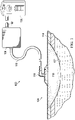
- FIGURE 1 is a sectional view of one embodiment of a therapy system 100 for supplying reduced pressure to a tissue site 102 that can remove liquid from fluid drawn from the tissue site 102.
- the therapy system 100 may include a dressing 104, a canister 106, and a reduced-pressure source 108.
- the dressing 104, the canister 106, and the reduced-pressure source 108 may be fluidly coupled by one or more conduits, such as a tube 110 fluidly coupling the dressing 104 to the canister 106, and a tube 112 fluidly coupling the canister 106 to the reduced-pressure source 108.
- tissue site in this context broadly refers to a wound or defect located on or within tissue, including but not limited to, bone tissue, adipose tissue, muscle tissue, neural tissue, dermal tissue, vascular tissue, connective tissue, cartilage, tendons, or ligaments.
- a wound may include chronic, acute, traumatic, subacute, and dehisced wounds, partial-thickness burns, ulcers (such as diabetic, pressure, or venous insufficiency ulcers), flaps, and grafts, for example.
- tissue site may also refer to areas of any tissue that are not necessarily wounded or defective, but are instead areas in which it may be desirable to add or promote the growth of additional tissue. For example, reduced pressure may be used in certain tissue areas to grow additional tissue that may be harvested and transplanted to another tissue location.
- components of the therapy system 100 may be coupled directly or indirectly.
- reduced-pressure source 108 may be directly coupled to the canister 106 and indirectly coupled to the dressing 104 through the canister 106.
- Components may be fluidly coupled to each other to provide a path for transferring fluids (i.e., liquid and/or gas) between the components.
- components may be fluidly coupled with the tube 110 and the tube 112, for example.
- a tube may be an elongated, cylindrical structure with some flexibility, but the geometry and rigidity may vary.
- components may additionally or alternatively be coupled by virtue of physical proximity, being integral to a single structure, or being formed from the same piece of material. Coupling may also include mechanical, thermal, electrical, or chemical coupling (such as a chemical bond) in some contexts.
- the fluid mechanics of using a reduced-pressure source to reduce pressure in another component or location, such as within a sealed therapeutic environment, can be mathematically complex.
- the basic principles of fluid mechanics applicable to reduced-pressure therapy are generally well-known to those skilled in the art, and the process of reducing pressure may be described illustratively herein as "delivering,” “distributing,” or “generating” reduced pressure, for example.
- exudates and other fluids flow toward lower pressure along a fluid path.
- This orientation may generally be presumed for purposes of describing various features and components of reduced-pressure therapy systems herein.
- downstream typically implies something in a fluid path relatively closer to a reduced-pressure source
- upstream implies something relatively further away from a reduced-pressure source.
- the fluid path may also be reversed in some applications (such as by substituting a positive-pressure source for a reduced-pressure source) and this descriptive convention should not be construed as a limiting convention.
- Reduced pressure generally refers to a pressure less than a local ambient pressure, such as the ambient pressure in a local environment external to a sealed therapeutic environment provided by the dressing 104.
- the local ambient pressure may also be the atmospheric pressure at which a tissue site is located.
- the pressure may be less than a hydrostatic pressure associated with tissue at the tissue site.
- values of pressure stated herein are gauge pressures.
- references to increases in reduced pressure typically refer to a decrease in absolute pressure, while decreases in reduced pressure typically refer to an increase in absolute pressure.
- the dressing 104 generally may include a cover, such as a drape 114, a tissue interface, such as a manifold 116, and a connector, such as an adapter 118.
- the manifold 116 may be placed within, over, on, or otherwise proximate to a tissue site, such as the tissue site 102.
- the drape 114 may be placed over the manifold 116 and sealed to tissue proximate to the tissue site 102.
- the tissue proximate to the tissue site 102 is often undamaged epidermis peripheral to the tissue site 102.
- the dressing 104 can provide a sealed therapeutic environment proximate to the tissue site 102 that may be substantially isolated from the external environment, and the reduced-pressure source 108 can reduce the pressure in the sealed therapeutic environment.
- Reduced pressure applied across the tissue site 102 through the manifold 116 in the sealed therapeutic environment can induce macrostrain and microstrain in the tissue site 102, as well as remove exudates and other fluids from the tissue site 102. Exudate and other fluid from the tissue site 102 can be collected in the canister 106 and disposed of properly.
- the drape 114 may be an example of a sealing member.
- a sealing member may be constructed from a material that can provide a fluid seal between two components or two environments, such as between a therapeutic environment and a local external environment.
- the sealing member may be, for example, an impermeable or semi-permeable elastomeric material that can provide a seal adequate to maintain a reduced pressure at a tissue site for a given reduced-pressure source.
- the permeability generally should be low enough that a desired reduced pressure may be maintained.
- An attachment device may be used to attach a sealing member to an attachment surface, such as undamaged epidermis, a gasket, or another sealing member.
- the attachment device may take many forms.
- an attachment device may be a medically acceptable, pressure-sensitive adhesive that may extend about a periphery, a portion of, or an entirety of the sealing member.
- Other example embodiments of an attachment device may include a double-sided tape, paste, hydrocolloid, hydrogel, silicone gel, organogel, or an acrylic adhesive.
- the manifold 116 can be generally adapted to contact the tissue site 102.
- the manifold may be partially or fully in contact with the tissue site 102. If the tissue site 102 is a wound, for example, the manifold 116 may partially or completely fill the wound, or may be placed over the wound.
- the manifold 116 may take many forms, and may have many sizes, shapes, or thicknesses depending on a variety of factors, such as the type of treatment being implemented or the nature and size of the tissue site 102. For example, the size and shape of the manifold 116 may be adapted to the contours of deep and irregular shaped tissue sites.
- a manifold may be a substance or structure adapted to distribute reduced pressure across a tissue site, remove fluids from across a tissue site, or distribute reduced pressure and remove fluids across a tissue site.
- a manifold may also facilitate delivering fluids to a tissue site, if the fluid path is reversed or a secondary fluid path is provided, for example.
- a manifold may include liquid channels or pathways that distribute fluids provided to and removed from a tissue site around the manifold.
- the liquid channels or pathways may be interconnected to improve distribution or removal of fluids across a tissue site.
- cellular foam, open-cell foam, porous tissue collections, and other porous material such as gauze or felted mat
- cellular foam, open-cell foam, porous tissue collections, and other porous material generally include structural elements arranged to form liquid channels.
- Liquids, gels, and other foams may also include or be cured to include liquid channels.
- the manifold 116 may be a porous foam material having interconnected cells or pores adapted to distribute reduced pressure across the tissue site 102.
- the foam material may be either hydrophobic or hydrophilic.
- the manifold 116 can be an open-cell, reticulated polyurethane foam such as GranuFoam ® dressing available from Kinetic Concepts, Inc. of San Antonio, Texas.
- the manifold 116 may also wick fluid away from the tissue site 102, while continuing to distribute reduced pressure to the tissue site 102.
- the wicking properties of the manifold 116 may draw fluid away from the tissue site 102 by capillary flow or other wicking mechanisms.
- An example of a hydrophilic foam may be a polyvinyl alcohol, open-cell foam such as V.A.C. WhiteFoam ® dressing available from Kinetic Concepts, Inc. of San Antonio, Texas.
- Other hydrophilic foams may include those made from polyether.
- Other foams that may exhibit hydrophilic characteristics include hydrophobic foams that have been treated or coated to provide hydrophilicity.
- the manifold 116 may further promote granulation at the tissue site 102 if pressure within the sealed therapeutic environment is reduced.
- any or all of the surfaces of the manifold 116 may have an uneven, coarse, or jagged profile that can induce microstrains and stresses at the tissue site 102 if reduced pressure is applied through the manifold 116.
- the manifold may be constructed from bioresorable materials. Suitable bioresorbable materials may include, without limitation, a polymeric blend of polylactic acid (PLA) and polyglycolic acid (PGA). The polymeric blend may also include without limitation polycarbonates, polyfumarates, and capralactones.
- the manifold 116 may further serve as a scaffold for new cell-growth, or a scaffold material may be used in conjunction with the manifold 116 to promote cell-growth.
- a scaffold is generally a substance or structure used to enhance or promote the growth of cells or formation of tissue, such as a three-dimensional porous structure that provides a template for cell growth.
- Illustrative examples of scaffold materials include calcium phosphate, collagen, PLA/PGA, coral hydroxy apatites, carbonates, or processed allograft materials.
- a reduced-pressure source such as the reduced-pressure source 108, may be a reservoir of air at a reduced pressure, or may be a manually or electrically-powered device that can reduce the pressure in a sealed volume, such as a vacuum pump, a suction pump, a wall suction port available at many healthcare facilities, or a micro-pump, for example.
- the reduced-pressure source may be housed within or used in conjunction with other components, such as sensors, processing units, alarm indicators, memory, databases, software, display devices, or user interfaces that further facilitate reduced-pressure therapy. While the amount and nature of reduced pressure applied to a tissue site may vary according to therapeutic requirements, the pressure typically ranges between -5 mm Hg (-667 Pa) and -500 mm Hg (-66.7 kPa). Common therapeutic ranges are between -75 mm Hg (-9.9 kPa) and -300 mm Hg (-39.9 kPa).
- the canister 106 may be representative of a container, canister, pouch, or other storage component that can be used to manage exudate and other fluid withdrawn from a tissue site.
- a rigid container may be preferred or required for collecting, storing, and disposing of fluid.
- fluid may be properly disposed of without rigid container storage, and a re-usable container could reduce waste and costs associated with reduced-pressure therapy.
- the canister 106 may be fluidly coupled to the dressing 104 with the tube 110 and fluidly coupled to the reduced-pressure source 108 with the tube 112.
- the reduced-pressure source 108 supplies reduced pressure to the canister 106 through the tube 112 and to the dressing 104 through the canister 106 and the tube 110. In this manner, the reduced-pressure source 108 may draw fluid, including exudate from the tissue site 102 into the canister 106.
- a reduced-pressure source may draw fluid from a tissue site into a canister, such as the canister 106.
- the fluid drawn from a tissue site may have a high content of evaporated liquid, giving the fluid a high relative humidity.
- a canister is coupled to a tissue site through a tube, as in therapy system 100, a portion of the evaporated liquid may condense in the tube. This may occur due to the cooler ambient environment surrounding the tube, for example.
- the fluid, including the condensed liquid in the tube may be drawn into the canister by the reduced-pressure source.
- the fluids in a canister may have a relative humidity as high as about 70%, for example. This relative humidity depends, in part, on the ambient temperature around a canister, the location of the canister, the orientation of the canister, how much liquid may be in the canister, and the type of liquid, including exudate, in the canister.
- humid fluid may also be drawn from a canister into the tube coupled to the reduced-pressure source. There, further liquid may condense from the fluid in the tube. The condensed liquid in the tube may be drawn into the reduced-pressure source, which may cause the reduced-pressure source to operate improperly or stop functioning altogether.
- a canister and reduced-pressure source may be jointly housed within an integral therapy unit. These units may face problems similar to those described above, as highly humid fluid may be drawn from the canister into the reduced-pressure source.
- some canisters may expel the highly humid fluid onto an inside face of the canister before drawing the fluid into a reduced-pressure source. There, the fluid can cool and liquid may condense out of the fluid. The condensation on the inside face of the canister may cause the canister to appear to be leaking.
- Other canisters expel fluid from the canister into an internal location of a combined canister and reduced-pressure source unit. In these canisters, liquid can condense from the fluids within this structure and can cause the canister to appear to be contaminated. Condensed liquid within the structure may also lead to the growth of flora.
- flora within the structure may lead to growth of flora elsewhere in a therapy system that may be detrimental to the health of the person receiving reduced-pressure therapy.
- Still other canisters may expel the fluid directly into a pump chamber of a reduced-pressure source. Condensed liquid in a pump chamber can cause failure of pump seals, failure of electrical connections within the pump, and a reduced ability to provide reduced-pressure therapy. Systems having a higher fluid flow tolerance may experience a magnification of the problems described above.
- the therapy system 100 can overcome these shortcomings and others by providing a moisture trap associated with the canister that can reduce the liquid content of fluid leaving the canister 106.
- a moisture trap is fluidly coupled between a fluid reservoir of the canister 106 and a reduced-pressure source 108.
- At least one barrier may be disposed within some embodiments of the moisture trap, providing an indirect fluid path between the fluid reservoir and the reduced-pressure source 108.
- the barrier preferably comprises a hydrophilic material or a hydrophilic surface.
- a sump may also be disposed within the moisture trap in fluid communication with the barrier to receive liquid condensed thereon.
- the moisture trap comprises a barrier and a sump adapted to receive condensation from the barrier, wherein the barrier comprises a hydrophilic surface and defines an indirect fluid path between the fluid reservoir and the reduced-pressure source.
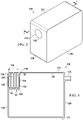
- FIGURE 2 is a perspective view illustrating additional details that may be associated with an example embodiment of the canister 106.
- the canister 106 may include a fluid outlet, such as an opening 124, and a filter 126 disposed within the opening 124.
- the filter 126 may be a hydrophobic filter, for example, configured to limit or reduce the number of particulates, including liquids, passing through the opening 124.
- an adapter or connector (not shown) may be disposed over the opening 124 to facilitate coupling between the opening 124 and a tube, such as the tube 112.
- the canister 106 may also include three pairs of opposing walls, such as end walls 128, side walls 129, and top and bottom walls 131.
- FIGURE 3 is a sectional view illustrating additional details that may be associated with example embodiments of the canister 106.
- the canister 106 may also include a fluid inlet, such as port 122.
- the port 122 may facilitate coupling the canister 106 to a tube, such as the tube 110.
- the opening 124 and the port 122 may be located on other portions of the canister 106.
- the end walls 128, the side walls 129, and the top and bottom walls 131 form a six-sided body.
- the end walls 128, the side walls 129, and the top and bottom walls 131 each join adjacent walls at an approximately ninety degree angle.
- the canister 106 may have flexible walls or other shapes, for example, spherical or pyramidal.
- the end walls 128 couple to the top and bottom walls 131 and the side walls 129 to form a fluid reservoir 120.
- the illustrative canister 106 also may include a moisture trap 130.
- the moisture trap 130 in this example embodiment may be fluidly coupled between the fluid reservoir 120 and the reduced-pressure source 108.
- the moisture trap 130 can be disposed within the canister 106 proximate to the opening 124 so that fluid flowing from the fluid reservoir 120 passes through the moisture trap 130 before passing through the opening 124.
- the moisture trap 130 generally may include a first wall 132, a second wall 134, and at least one fluid barrier, such as a plate 138. As illustrated in FIGURE 3 , the first wall 132 and the second wall 134 can join at ends of each wall at an angle of approximately 90 degrees. The first wall 132 and the second wall 134 may be joined at opposite ends to the walls of the canister 106 that form the fluid reservoir 120. In some embodiments, the moisture trap 130 may be secured to or otherwise disposed adjacent to the opening 124 without joining the first wall 132 or the second wall 134 to the walls of the canister 106. The first wall 132 may generally be parallel to the opening 124 and separated from the opening 124 by a distance 136.
- the distance 136 may be a portion of a total length of the canister 106. In some embodiments, the distance 136 may extend a majority of the length of the canister 106. In other embodiments, the distance 136 may extend less than about one-half of the length of the canister 106. As illustrated, in some embodiments the second wall 134 may generally be perpendicular to the first wall 132. In the illustrated embodiment, the first wall 132 and the second wall 134 fluidly isolate a portion of the fluid reservoir 120 proximate to the opening 124 from the remaining portions of the fluid reservoir 120.
- the first wall 132 may have an opening 133 similar to the opening 124, as illustrated in FIGURE 3 .
- the opening 133 can permit fluid communication between the fluid reservoir 120 and the moisture trap 130.
- a filter 135 may be disposed within the opening 133.
- the filter 135 may be similar to the filter 126 and may be a hydrophobic filter configured to limit or reduce the number of particulates, including liquids, passing through the opening 133.
- the moisture trap 130 may also include a sump, such as the sump 140.
- the sump 140 may be disposed adjacent to the second wall 134 and perpendicular to the first wall 132, as illustrated.
- the sump 140 may consist of or include a layer of material having a thickness less than a height of the first wall 132 and may extend the width of the moisture trap 130 between the side walls 129 of the canister 106.
- the sump 140 may include an absorbent material disposed within the moisture trap 130 to collect liquid condensed from fluid flowing through the moisture trap 130.
- the thickness of the absorbent material may vary as needed for the particular application of the moisture trap 130.
- the sump 140 may extend only a portion of the width of the moisture trap 130 to allow the sump 140 to expand as the sump 140 receives liquid, for example.
- the sump 140 may be fluidly isolated from the fluid reservoir 120 so that liquid in the fluid reservoir 120 may not interact with the sump 140.
- the liquid condensed from the fluid flowing through the moisture trap 130 may primarily be water, making materials formed of super absorbent polymers suitable for efficient use as the sump 140.
- the sump 140 may be sodium polyacrylate.
- the sump 140 may be BASF Luquasorb ® or Luquafleece ® 402C; Technical Absorbents Limited superabsorbent fibers, such as TAL 2327; Texsus spa FP2325; or an isolyser.
- the sump 140 may be an absorbent having carboxymethyl cellulose or alginates.
- a fluid barrier can be disposed between the first wall 132 and the opening 124.
- a fluid barrier may be a device configured to impede, restrict, or otherwise direct fluid flow.
- the fluid barrier of FIGURE 3 may include three plates 138 disposed in the fluid path between the opening 124 and the opening 133.
- a plate such as the plate 138, may be a generally rectangular piece of material. In some embodiments, a plate may be a solid piece of rectangular material.
- Each plate 138 may have a first end that can be joined to a wall.
- a first plate 138 may have a first end that joins to the second wall 134; a second plate 138 may have a first end that joins to a wall forming a portion of the canister 106; and a third plate 138 may have a first end that joins to the second wall 134.
- Each plate 138 in this example embodiment may have a second end separated from the wall proximate to the second end. The separation may form a gap between the wall proximate to the second end and the second end of each plate 138.
- each plate 138 that are perpendicular to the first end and the second end may be joined to the side walls 129 forming the canister 106 and the fluid reservoir 120 so that fluid communication around each plate 138 may only occur across the second end of each plate 138.
- Each plate 138 may be in a parallel juxtaposition, for example, each plate 138 may be positioned so that the plate 138 may be parallel to the first wall 132 and to adjacent plates 138. Each plate 138 may also be disposed within the moisture trap 130 and oriented so that a plane in which the plate 138 is disposed may intersect a plane in which the sump 140 is disposed. For example, the plates 138 may all be perpendicular to the sump 140 in some embodiments. In other embodiments, the plates 138 may not be perpendicular to the sump 140, but may also not be parallel to the sump 140.
- first end of a plate 138 proximate to the first wall 132 may be joined to the second wall 134 so that fluid passes between the second end of the plate 138 and the top wall of the top and bottom walls 131 forming an exterior of the canister 106.
- the plate 138 proximate to the opening 124 may also be joined to the second wall 134 so that there may be a gap between the second end of the plate 138 and the top wall 131 forming the exterior of the canister 106.
- the plate 138 disposed near a center portion of the second wall 134 may be joined to the top wall 131 forming an exterior of the canister 106 so that there may be a gap between the second end of the plate 138 and the second wall 134.
- the plates 138 form an indirect fluid path between the opening 133 and the opening 124.
- an "indirect" fluid path may be a fluid path between two locations having at least one change of direction between the two locations.
- An indirect fluid path may also be referred to as a "tortuous" fluid path, a "labyrinthine” fluid path, or a "convoluted" fluid path.
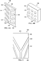
- FIGURE 4A is a perspective view illustrating additional details that may be associated with some embodiments of the plates 138 of FIGURE 3 .
- the plate 138 may include one or more liquid channels 144 disposed on a surface of the plate 138, such as a condensation surface 142.
- a channel, such as the channel 144 may be a portion of the plate 138 configured to direct liquid by providing a preferential path for liquid flow.
- the plate 138 may include the liquid channels 144 on both sides of the plate 138.
- the condensation surface 142 may be preferably a hydrophilic surface, either wholly or in part.
- a surface that is hydrophilic may be a surface treated with a material or formed from a material that is molecularly attractive to water.
- the condensation surface 142 may be a portion of the plate 138 formed of a hydrophilic material or having a hydrophilic material disposed thereon.
- the liquid channels 144 may be hydrophobic in some embodiments.
- the barrier comprises a hydrophilic surface and a hydrophobic channel adapted to direct condensation to the sump.
- Hydrophobic materials may be materials that are treated with or formed from a material that is molecularly repulsive to water.
- the liquid channels 144 may be formed of a hydrophobic material or have a hydrophobic material disposed thereon, which may facilitate movement of liquid through the liquid channels 144.
- the plate 138 may have a collection end 148 and a drainage end 150. The plate 138 may be oriented within the moisture trap 130 so that the drainage end 150 may be proximate to or adjacent to the sump 140.
- the liquid channels 144 may form pathways configured to direct condensed liquid toward the drainage end 150 and the sump 140.
- the liquid channels 144 include a central channel 145 proximate to a center portion of the plate 138, and the central channel 145 may have a terminus 147 proximate to the drainage end 150.
- Tributary channels 149 may extend from the edges of the plate 138 toward the central channel 145 and generally toward the drainage end 150 so that the liquid channels 144 form a fletching pattern.
- the tributary channels 149 in the example embodiment of FIGURE 4A are generally configured to direct liquid from outer portions of the plate 138 toward the central channel 145.
- the plate 138 may be oriented within the moisture trap 130 so that the liquid channels 144 may be aided by gravity.
- FIGURE 4B is a detail perspective view illustrating additional details that may be associated with the example embodiment of the plate 138 illustrated in FIGURE 4A .
- the condensation surface 142 may have a rough finish.
- the condensation surface 142 may have bumps, nodules, protuberances or other forms of protrusions, illustrated in FIGURE 4B as protrusions 146.
- the protrusions 146 may protrude between about 15 microns and about 20 microns from the surrounding condensation surface 142, and are also preferably hydrophilic.
- the protrusions 146 may be spherical, conical, pyramidal, grooves, other polygons, or may have an amorphous or irregular shape, for example.
- the protrusions 146 may be formed by injection molding, stamping, hot or cold rolling, chemical and photo lithographic etching, micro machining, or bead, sand, or vapor blasting of the plate 138.
- the barrier in the moisture trap 130 may be a porous plate, mesh, net, or fabric that permits fluid to flow through it.
- the porous plate, mesh, net, or fabric forms an indirect fluid flow path as the porous plate, mesh, net, or fabric may impede the flow of fluid from the opening 133 to the opening 124.
- the porous plate, mesh, net, or fabric may be formed of a plurality of obstructions, such as the fibers of a woven fabric that may cause the fluid to change directions in response to interaction with the obstruction; thus, such obstructions form an indirect fluid path between the opening 133 and the opening 124. For example, if each plate 138 is a porous plate and extends from the top wall 131 to the second wall 134, then fluid can flow through the plate 138 rather than around the plate 138.
- the porous plate, mesh, net, or fabric may be formed of a hydrophilic material, or be treated to impart hydrophilic properties to the material.
- the liquid channels 144 may be formed on the porous plate, mesh, net, or fabric.
- the porous plate, mesh, net, or fabric may have a wax coating to form the liquid channels 144.
- the liquid channels 144 may be formed on the porous plate, mesh, net, or fabric versions of the plate 138, for example, the area of the material where the liquid channels 144 are desired could be fused together and treated to impart hydrophobic properties.
- the porous plate, mesh, net, or fabric versions of the plate 138 may be formed from a woven or non-woven material, a foam, a sintered polymer or formed from a solid piece of material formed to have pores. Nets or meshes may be extruded or expanded to increase the flow area; however, the surface area available for condensation should be maximized.
- the porous plate, mesh, net, or fabric versions of the plate 138 may be stacked or layered with additional plates 138.
- the plate 138 may be manufactured from a hydrophilic material, for example, and then treated to form the liquid channels 144. Formation of the liquid channels 144 may be accomplished by plasma coating, for example. In plasma coating, plasma may be used to deposit a thin coating of a compound designed to alter the level of hydrophilicity. For example, the plasma coating processes developed by P2i Limited may be used to form the liquid channels 144. In other embodiments, the plate 138 may be formed of a hydrophobic material. The plate 138 may then be treated to form the condensation surface 142. Formation of the condensation surface 142 may be done with a plasma coating process or a wet coating process, for example.
- a wet coating process or a chemical vapor deposition process may be used to deposit Parylene to form the condensation surface 142.
- a corona or plasma coating process may oxidize the surface of the plate 138 to form the condensation surface 142.
- Hydak ® manufactured by Biocoat, Inc. may also be used to treat the plate 138 to form the condensation surface 142.
- the plate 138 may not include the liquid channels 144.
- the condensation surface 142 may encompass the entirety of the plate 138. Generally, in embodiments having both the condensation surface 142 and the liquid channels 144, the condensation surface 142 may be greater than or equal to about 80% of the plate 138.
- FIGURE 5 is a front view of another embodiment of a plate that may be used as a fluid barrier in some embodiments of the moisture trap 130.
- a plate 238 may include a collection end 248, a drainage end 250, a condensation surface 242, and one or more liquid channels 244.
- the plate 238 may be of a similar size, have similar properties, and operate in a manner similar to the plate 138 of FIGURE 4A .
- the liquid channels 244 may have additional shapes as desired to direct liquid as needed in the particular embodiment of the moisture trap 130.
- the reduced-pressure source 108 can supply reduced pressure to the dressing 104 through the canister 106, drawing fluid from the tissue site 102 into the fluid reservoir 120 through the port 122. Fluid may be stored in the fluid reservoir 120 and fluid having evaporated liquid therein may be drawn into the moisture trap 130 through the opening 133.
- the filter 135 may prevent condensed liquid from passing from the fluid reservoir 120 into the moisture trap 130 so that fluid entering the moisture trap 130 may be composed primarily of gas and evaporated liquid.
- the reduced-pressure source 108 can also draw the gas and evaporated liquid through the indirect fluid path provided by the moisture trap 130. Fluid having gas and evaporated liquid may be exposed to a surface of each plate 138 as it moves through the indirect fluid path of the moisture trap 130.
- the indirect fluid path formed by the plates 138 can direct fluid toward the top wall 131 forming the exterior of the canister 106 around the second end of the plate 138 and toward the second wall 134 so that the fluid on a first side of the plate 138 flows in an opposite direction from fluid flowing on a second side of the plate 138.
- the indirect fluid path can move fluid in opposing directions on opposite sides of each plate 138.
- the condensation surface 142 may be a portion of the plate 138 that is attractive to liquid so that liquid evaporated in fluid flowing adjacent to the condensation surface 142 of the plate 138 may be urged to condense from the fluid onto the condensation surface 142.
- the protrusions 146 and the hydrophilic properties of the condensation surfaces 142 can cause the evaporated liquid to condense onto the condensation surfaces 142.
- the protrusions 146 may aid in condensation by acting as preferential sites for nucleation that condenses liquid from the fluid passing by the condensation surface 142.
- the protrusions 146 may also aid in moving liquid condensed onto the condensation surface 142 toward the liquid channels 144.
- the liquid may be urged toward the sump 140 by the liquid channels 144. If the liquid reaches the sump 140, the liquid may be trapped by the sump 140. In this manner, the liquid content of fluid leaving the canister 106 may be reduced.
- FIGURE 6 is a perspective view illustrating another example embodiment of a moisture trap 330
- FIGURE 7 is a cut-away view illustrating additional details of the moisture trap 330.
- the moisture trap 330 may operate in a manner similar to the moisture trap 130, modified as described in more detail below.
- the moisture trap 330 may be a cylindrical body having a top wall 302, a bottom wall 304, and a cylindrical side wall 306.
- the cylindrical side wall 306 may be coupled to a peripheral portion of the bottom wall 304 and to a peripheral portion of the top wall 302.
- the top wall 302, the bottom wall 304, and the cylindrical side wall 306 form an interior 308, which can be fluidly isolated from an ambient environment.
- the illustrative embodiment of the moisture trap 330 also may include a fluid inlet 333 and a fluid outlet 324.
- the fluid inlet 333 may be disposed proximate to the cylindrical side wall 306 and a peripheral portion of the bottom wall 304.
- the fluid outlet 324 may be disposed proximate to a center portion of the top wall 302 and be may generally be aligned with an axis of the moisture trap 330.
- Both the fluid inlet 333 and the fluid outlet 324 may be cylindrical bodies configured to be fluidly coupled to a conduit so that the moisture trap 330 may be disposed in a fluid path between a fluid reservoir and a reduced-pressure source.
- the moisture trap 330 may be fluidly coupled between the fluid reservoir 120 of the canister 106 and the reduced-pressure source 108 of FIGURE 1 .
- Filters 335 and 326 may also be disposed within the fluid inlet 333 and the fluid outlet 324, respectively.
- the filters 335 and 326 may be similar to the filters 135 and 126 of FIGURE 1 , and may also be formed of a hydrophobic material.
- the fluid inlet 333 may have a cylindrical wall extending into the interior 308 from the bottom wall 304 so that a terminus of the fluid inlet 333 may be separated from an interior surface of the bottom wall 304.
- the moisture trap 330 also may include a sump 340, which may be similar in many respects to the sump 140.
- the sump 340 may be disposed adjacent to the bottom wall 304.
- the sump 340 may include a layer of absorbent material having a thickness less than the height of the cylindrical side wall 306 and may be coextensive with the bottom wall 304. In some embodiments, the thickness of the absorbent material may vary as needed for the particular application of the moisture trap 330.
- the sump 340 may not be coextensive with the bottom wall 304 of the moisture trap 330 to allow the sump 340 to expand as the sump 340 receives liquid, for example.
- the sump 340 can be fluidly isolated from a fluid reservoir so that liquid in the fluid reservoir may not interact with the sump 340.
- Liquid condensed from fluid flowing through the moisture trap 330 may primarily be water, making materials formed of super-absorbent polymers suitable for efficient use as the sump 340.
- the sump 340 may be sodium polyacrylate.
- the sump 340 may be BASF Luquasorb ® or Luquafleece ® 402C; Technical Absorbents Limited superabsorbent fibers, such as TAL 2327; Texsus spa FP2325; or an isolyser.
- the sump 340 may be an absorbent having carboxymethyl cellulose or alginates.
- the moisture trap 330 also may include a fluid barrier, such as a spiral barrier 338.
- the spiral barrier 338 may be similar to the plate 138 in some respects.
- the spiral barrier 338 may be an Archimedean spiral having a first end 310, a second end 312, and opposing lateral edges 314, 316.
- the spiral barrier 338 may have other spiral shapes such as Cornu, Fermat, hyperbolic, lituus, or logarithmic spirals, for example.
- the spiral barrier 338 may be disposed within the interior 308 so that the first end 310 may be proximate to the fluid inlet 333 and the second end 312 may be proximate to the fluid outlet 324.
- the first end 310 may be adjacent to the cylindrical side wall 306 so that fluid may not flow between the first end 310 and the cylindrical side wall 306. In other embodiments, the first end 310 may be proximate to the cylindrical side wall 306 and allows fluid flow between the first end 310 and the cylindrical side wall 306.
- the opposing lateral edges 314, 316 may be coupled to the top wall 302 and the bottom wall 304, respectively, to prevent fluid communication between the opposing lateral edges 314, 316 and the top wall 302 and the bottom wall 304.
- the spiral barrier 338 may also include condensation surfaces and liquid channels similar to the condensation surfaces 142 and the liquid channels 144 of the plate 138.
- the condensation surfaces may operate similar to the condensation surface 142 and the liquid channels may direct fluid to the sump 340 similar to the liquid channels 144.
- the condensation surfaces and the liquid channels may also be formed in a manner similar to the condensation surface 142 and the liquid channels 144.
- the spiral barrier 338 may be a single member formed to have the spiral shape.
- the spiral barrier 338 may be manufactured by rolling a strip of a plate-like material to form the desired shape, for example. In some embodiments, a strip of material may be bent to form the desired shape. In still other embodiments, the spiral barrier 338 may be formed of multiple members joined to form the spiral shape.
- fluid may enter the moisture trap 330 through the fluid inlet 333 proximate to the first end 310 of the spiral barrier 338, and may flow adjacent to the surface of the spiral barrier 338.
- the curve of the spiral barrier 338 may be adapted to direct fluid along a spiral path toward the second end 312 of the spiral barrier 338 proximate to the fluid outlet 324.
- the spiral barrier 338 forms an indirect fluid path between the fluid inlet 333 and the fluid outlet 324 by changing the direction of the fluid as the fluid flows between the fluid inlet 333 and the fluid outlet 324.
- hydrophilic condensation surfaces may cause liquid to condense from the fluid onto the surface of the spiral barrier 338.
- FIGURE 8 is a partial sectional view illustrating details of another illustrative embodiment of a moisture trap 430 that may be associated with the therapy system 100.
- a portion of a canister 406 is also illustrated in FIGURE 8 , having the illustrative moisture trap 430 disposed therein.
- the canister 406 may be similar to the canister 106 in many respects, and generally may include a fluid outlet 424 having a filter 426 disposed therein.
- the fluid outlet 424 may be similar to and operate like the opening 124 and the fluid outlet 324, and the filter 426 may be similar to and operate like the filter 126 and the filter 326 described above.
- the canister 406 may include an end wall 428 and a top wall 431.
- the end wall 428 and the top wall 431 may be similar to and operate in a manner similar to the end walls 128 and the top and bottom walls 131 of FIGURE 2 .
- the example embodiment of the moisture trap 430 illustrated in FIGURE 8 generally may include a first wall 432 and a second wall 434, which may be joined orthogonally.
- the second wall 434 may be joined at an opposite end to the end wall 428 of the canister 406.
- the first wall 432 may generally be parallel to the fluid outlet 424 and separated from the fluid outlet 424 by a distance 436.
- the distance 436 may be a portion of a total length of the canister 406. In some embodiments, the distance 436 may extend a majority of the length of the canister 406.
- the distance 436 may extend less than about one-half of the length of the canister 406.
- the second wall 434 may generally be perpendicular to the first wall 432. Both the first wall 432 and the second wall 434 may have side ends perpendicular to the first end and the second end that join to the side walls forming the canister 406.
- the first wall 432 may extend from the second wall 434 toward the top wall 431 of the canister 406 a portion of the distance between the second wall 434 and the top wall 431 of the canister 406. This may form an opening 433 that permits fluid communication between the moisture trap 430 and a fluid reservoir of the canister 406.
- the first wall 432 may join the top wall 431 of the canister 406 and the opening 433 may be formed in the first wall 432 similar to the first wall 132 and the opening 133.
- a filter may be disposed within the opening 433. In the example embodiment of FIGURE 8 , the opening 433 does not have a filter.
- the moisture trap 430 may also include a sump 440.
- the sump 440 may be disposed adjacent to the second wall 434 and perpendicular to the first wall 432.
- the sump 440 may include an absorbent layer having a thickness less than the height of the first wall 432, and may be coextensive with the second wall 434 in some embodiments. In some embodiments, the thickness of the absorbent layer may vary as needed for the particular application of the moisture trap 430.
- the sump 440 may extend only a portion of the second wall 434 of the moisture trap 430 to allow the sump 440 to expand as the sump 440 receives fluid, for example.
- the sump 440 can be fluidly isolated from the fluid reservoir in some embodiments so that liquid in the fluid reservoir may not interact with the sump 440.
- Liquid condensed from the fluid flowing through the moisture trap 430 may primarily be water, making materials formed of super absorbent polymers suitable for efficient use as the sump 440.
- the sump 440 may be sodium polyacrylate.
- the sump 440 may be BASF Luquasorb ® or Luquafleece ® 402C; Technical Absorbents Limited superabsorbent fibers, such as TAL 2327; Texsus spa FP2325; or an isolyser.
- the sump 440 may be an absorbent having carboxymethyl cellulose or alginates.
- the moisture trap 430 may also include a barrier, such as an array 438 of cells 450.
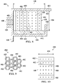
- FIGURE 9 is a top view of the array 438
- FIGURE 10 is side elevation view of the array 438, illustrating additional details that may be associated with some embodiments.
- the array 438 may include a cluster of individual cells 450 having cell walls 452.
- a cell such as each cell 450, may be a component that may be combined with other substantially identical components to form a whole.
- the cell walls 452 of each cell 450 may be interconnected or shared with the cell walls 452 of adjacent cells 450 so that the plurality of cells 450 form the interconnected structure of the array 438.
- each cell 450 may have a hexagonal shape with six cell walls 452. In other embodiments, each cell 450 may have a circular, square, triangular, rhomboidal, or amorphous shape.
- the cell walls 452 in the illustrative embodiment may each form a channel 460 extending through each cell 450 from a first end 456 to a second end 458.
- the cell walls 452 may have a length 454 so that each cell 450 may extend from the top wall of the top and bottom walls 431 of the canister 406 to the sump 440.
- Each channel 460 may be open at the second end 458 of the cell 450 so that the channel 460 may be in fluid communication with the sump 440. In some embodiments, the channel 460 may be open at the first end 456.
- Each cell wall 452 may include a plurality of perforations 462.
- the perforations 462 may extend through the cell wall 452 so that fluid may communicate through the cell wall 452.
- the perforations 462 may permit fluid communication between the channel 460 and an ambient environment, for example a fluid reservoir of the canister 406.
- the perforations 462 may also permit fluid communication between the channels 460 of adjacent cells 450 having an interconnected cell wall 452.
- each cell 450 may have a distance between parallel sides, that is, across the flats, of about 6 mm. The size of the cells 450 may be reduced to increase the available surface area provided the by cell walls 452, thus increasing the ability of the cells 450 to cause condensation.
- the cells 450 may be formed of a thermoplastic and may have hydrophilic properties.
- the cells 450 may be formed of a material such as those manufactured by Baltex, Plascore, Inc., or Hexacor Limited. In some embodiments, these materials may be referred to as a 3-D fabric.
- 3-D fabrics may be materials having the flexibility associated with fabric while having length, width, and depth. Some 3-D fabrics may be formed similar to the array 438 described above. Other 3-D fabrics may be formed having two layers of woven material joined by a plurality of fibers. The material may also be treated similar to the plate 138 to vary the hydrophilicty of the material as desired for the particular application of the array 438.
- the array 438 can be disposed between the sump 440 and the top wall 431 of the canister 406 so that the array 438 can provide a barrier to fluid flow between a fluid reservoir of the canister 406 and the fluid outlet 424.
- the array 438 may be coupled to the top wall 431 and side walls of the canister 406 so that the fluid path flows through the array 438.
- the fluid may flow through the array 438 by passing through the perforations 462 in each cell wall 452.
- each cell 450 may be hexagonal and joined to at least two adjacent cells 450 so that the perforations 462 may not form a straight flow path from the opening 433 to the fluid outlet 424.
- the reduced-pressure source 108 can supply reduced pressure to the dressing 104 through the canister 406, drawing fluid from the tissue site 102 into the canister 106. Fluid may be stored in a fluid reservoir of the canister 106 and fluid having evaporated liquid therein may be drawn into the moisture trap 430 through the opening 433. The reduced-pressure source 108 can also draw the gas and evaporated liquid through an indirect fluid path formed by the array 438. As fluid passes through a perforation 462 in a first cell wall 452 of a cell 450 the fluid may change direction to reach the fluid outlet 424.
- the fluid flow should eventually abut the top wall 431, the side walls of the canister 406, or the second wall 434 before reaching the fluid outlet 424.
- the top wall 431 and the side walls of the canister 406 or the second wall 434 can cause a change in the direction of the fluid flow.
- the plurality of cells 450 can form an indirect fluid path.
- the array 438 can provide a large condensation area by increasing the surface area that the fluid may contact as it passes through the moisture trap 430. As gas and evaporated liquid flow across the surfaces of the cells 450, evaporated liquid can condense onto the cell walls 452.
- the liquid may be urged toward the sump 440 by the channels 460. If liquid reaches the sump 440, the liquid may be trapped by the sump 440. In this manner, the moisture content of fluid leaving the canister 406 may be reduced.
- the sump 440 and the array 438 may be joined to form a multi-function fluid management laminate.
- FIGURE 11 is a side sectional view illustrating another example embodiment of a moisture trap 530 disposed in a canister 506.
- the canister 506 may be similar to the canister 106 in many respects, modified as described below.
- the canister 506 in this example embodiment generally may include a fluid outlet 524 having a filter 526 disposed therein.
- the fluid outlet 524 may be similar to and operate like the opening 124, the fluid outlet 324, and the fluid outlet 424, and the filter 526 may be similar to and operate like the filter 126, the filter 326, and the filter 426 described above.
- the canister 506 may have an end wall 528 and a top wall 531.
- the end wall 528 and the top wall 531 may be similar to and operate in a manner similar to the end walls 128 and the top wall 131 of the canister 106 described above with respect to FIGURE 2 .
- the illustrative embodiment of the moisture trap 530 generally may include a first wall 532, a second wall 534, and a mesh barrier 538 having an upper layer 550, a lower layer 552, and a mesh layer 554.
- the first wall 532 and the second wall 534 may join at ends of each wall at an angle of approximately 90 degrees.
- the second wall 534 may be joined at an opposite end to the wall 528 of the canister 506.
- the first wall 532 may generally be parallel to the fluid outlet 524 and separated from the fluid outlet 524 by a distance 536.
- the distance 536 may be a portion of a total length of the canister 506. In some embodiments, the distance 536 may extend a majority of the length of the canister 506. In other embodiments, the distance 536 may extend less than about one-half of the length of the canister 506.
- the second wall 534 may generally be perpendicular to the first wall 532 and join the walls forming the canister 506 proximate to the fluid outlet 524. Both the first wall 532 and the second wall 534 have side ends perpendicular to the first end and the second end that may join to the side walls forming the canister 506.
- the first wall 532 may extend a portion of the perpendicular distance between the second wall 534 and the top wall 531 of the canister 506, forming an opening 533 that can permit fluid communication between the moisture trap 530 and a fluid reservoir of the canister 506.
- the first wall 532 may join the top wall 531 of the canister 506 and the opening 533 can be formed in the first wall 532, similar to the first wall 432 and the opening 433.
- a filter may be disposed within the opening 533. In the illustrated embodiment, the opening 533 does not have a filter.
- the example embodiment of the moisture trap 530 also may include a sump 540.
- the sump 540 may be disposed adjacent to the second wall 534 perpendicular to the first wall 532.
- the sump 540 may include a layer of absorbent material having a thickness less than the height of the first wall 532, and may be coextensive with the second wall 534. In some embodiments, the thickness of the absorbent material may vary as needed for the particular application of the moisture trap 530. In some embodiments, the sump 540 may not be coextensive with the second wall 534 of the moisture trap 530 to allow the sump 540 to expand as the sump 540 receives liquid, for example.
- the sump 540 may be fluidly isolated from a fluid reservoir so that liquids in the fluid reservoir may not interact with the sump 540.
- the sump 540 may be an absorbent material disposed within the moisture trap 530 to collect liquid condensed from fluid flowing through the moisture trap 530.
- Liquid condensed from fluid flowing through the moisture trap 530 may primarily be water, making materials formed of super-absorbent polymers suitable for efficient use as the sump 540.
- the sump 540 may be sodium polyacrylate.
- the sump 540 may be BASF Luquasorb ® or Luquafleece ® 402C; Technical Absorbents Limited superabsorbent fibers, such as TAL 2327; Texsus spa FP2325; or an isolyser.
- the sump 540 may be an absorbent having carboxymethyl cellulose or alginates.
- FIGURE 12 is a perspective view illustrating additional details of the mesh barrier 538.
- the illustrative mesh barrier 538 of FIGURE 12 generally may include the upper layer 550, the lower layer 552, and the mesh layer 554.
- the mesh barrier 538 may be oriented within the moisture trap 530 so that the upper layer 550 may be adjacent to the top wall 531 of the canister 506, and the lower layer 552 may be adjacent the sump 540.
- the mesh layer 554 can be disposed between and fluidly coupled to the upper layer 550 and the lower layer 552.
- the mesh barrier 538 may extend the entirety of the distance between the sump 540 and top wall 531.
- the top wall 531 may be parallel to the sump 540 so that fluid flowing in the moisture trap 530 may flow through the mesh barrier 538.
- the upper layer 550 and the lower layer 552 may be wicking layers in some embodiments, configured to draw liquid into the mesh layer 554 or into the sump 540.
- the mesh layer 554 may be formed of a yarn, for example, which may be treated or coated to have hydrophilic properties.
- the yarn may be manufactured from different materials with different hydrophilic, hydrophobic, or absorbent properties.
- the type of yarn can also be varied to vary the width of the mesh layer 554 and the mesh barrier 538.
- the mesh barrier 538 may be a spacer fabric produced by a knitting process, similar to those manufactured by Heathcoat Fabrics and Muler Textil.
- the mesh barrier 538 may be a material formed of hydrophilic fibers formed of Nylon 6/6, such as polyester.
- fluid can flow through the opening 533, encountering the mesh layer 554.
- the mesh layer 554 may be disposed in the fluid path between the opening 533 and the fluid outlet 524, causing fluid to flow in an indirect fluid path. Fibers forming the mesh layer 554 may cause fluid to make numerous changes of direction as fluid flows through the mesh layer 554. As fluid interacts with the mesh layer 554, hydrophilic properties of the mesh layer 554 may cause liquid to condense from the fluid.
- the mesh layer 554 may direct liquid along fibers of the mesh layer 554 into the lower layer 552.
- the lower layer 552 may wick liquid into the sump 540, where liquid can be stored. Fluid that may flow through the upper layer 550 may be directed into the mesh layer 554, where the mesh layer 554 may then cause liquid to condense from the fluid as described above.
- the illustrative moisture traps can significantly reduce liquid content of fluid that exits a canister.
- the moisture traps may also prevent condensate from appearing in places where liquid should not be and prevent condensed liquid from providing a false perception that the device or canister may have been damaged or may be leaking.
- the moisture traps may also reduce the maintenance and service costs of a device.
- the moisture traps can also make efficient use of a sump having a super-absorbent, as a super-absorbent sump can absorb more pure water condensed from fluid.
- the moisture traps may also trap volatile organic compounds and other airborne particulates as liquid condenses.
- Some embodiments of the moisture traps may also help to dispose of fluidly contaminated components. Some embodiments of the moisture traps can be incorporated into a canister with minimal cost and may be retrofitted to other standard (Bemis type) canisters. Still further, some embodiments of the moisture traps may be replaceable with each canister.
Description
- The present disclosure relates generally to medical treatment systems for treating tissue sites and processing fluids. More particularly, but not by way of limitation, the present disclosure relates to a canister having a device for the removal of liquid from a fluid.
- Clinical studies and practice have shown that reducing pressure in proximity to a tissue site can augment and accelerate growth of new tissue at the tissue site. The applications of this phenomenon are numerous, but is has proven particularly advantageous for treating wounds. Regardless of the etiology of a wound, whether trauma, surgery, or another cause, proper care of the wound is important to the outcome. Treatment of wounds with reduced pressure may be commonly referred to as "reduced-pressure wound therapy," but is also known by other names, including "negative-pressure therapy," "negative pressure wound therapy," and "vacuum therapy," for example. Reduced-pressure therapy may provide a number of benefits, including migration of epithelial and subcutaneous tissues, improved blood flow, and micro-deformation of tissue at a wound site. Together, these benefits can increase development of granulation tissue and reduce healing times.
- While the clinical benefits of reduced-pressure therapy are widely known, the cost and complexity of reduced-pressure therapy can be a limiting factor in its application, and the development and operation of reduced-pressure systems, components, and processes continues to present significant challenges to manufacturers, healthcare providers, and patients.
US 2011/0288512 A1 describes a device for removing fluids from a wound to a canister.
A moisture processing device is placed between the moisture processing device and a reduced-pressure-housing port. The moisture processing device comprises a housing having vapour-permeable membranes and a plurality of support members. The members form a grid and have a plurality of apertures. Wicking layers may be disposed between the vapour-permeable membranes and the remainder of the housing. - A system for treating a tissue site with reduced pressure according to the present invention comprises the technical features of claim 1. The system includes a dressing adapted to be placed adjacent to the tissue site and a canister having a fluid reservoir adapted to be fluidly coupled to the dressing. A moisture trap is fluidly coupled to the fluid reservoir. The moisture trap includes a barrier and a sump adapted to receive condensation from the barrier. A reduced-pressure source is adapted to be fluidly coupled to the moisture trap. The barrier includes a hydrophilic surface and defines an indirect fluid path between the fluid reservoir and the reduced-pressure source. The barrier further comprises a hydrophobic channel adapted to direct condensation to the sump.
- A selection of optional features is set out in the dependent claims.
- Other aspects, features, and advantages of illustrative embodiments according to the present disclosure will become apparent with reference to the drawings and detailed description that follow.
-
-
FIGURE 1 is sectional view illustrating an exemplary embodiment of a reduced-pressure therapy system in accordance with this specification; -
FIGURE 2 is a perspective view of an illustrative canister of the reduced-pressure therapy system ofFIGURE 1 ; -
FIGURE 3 is a sectional view of the canister ofFIGURE 2 having a moisture trap; -
FIGURE 4A is a perspective view of an illustrative plate of the moisture trap ofFIGURE 2 ; -
FIGURE 4B is a detailed perspective view of a portion of the plate ofFIGURE 4A ; -
FIGURE 5 is an elevation view of another embodiment of a plate of the moisture trap ofFIGURE 2 ; -
FIGURE 6 is a perspective view of another illustrative embodiment of a moisture trap that may be used with the reduced-pressure therapy system ofFIGURE 1 ; -
FIGURE 7 is a partial sectional perspective view of the moisture trap ofFIGURE 6 ; -
FIGURE 8 is a detail sectional view of a portion of an illustrative canister having another embodiment of a moisture trap that may be used with the reduced-pressure therapy system ofFIGURE 1 ; -
FIGURE 9 is a top view of an example of cellular material that can be used with the moisture trap ofFIGURE 8 ; -
FIGURE 10 is an elevation view of the cellular material ofFIGURE 9 ; -
FIGURE 11 is a detail sectional view of a portion of another illustrative canister having another example embodiment of a moisture trap that may be used with the reduced-pressure therapy system ofFIGURE 1 ; and -
FIGURE 12 is a perspective view of an example mesh material that can be used with the moisture trap ofFIGURE 11 . - Useful systems, methods, and apparatuses for removing liquid from fluid drawn from a tissue site in a reduced-pressure therapy environment are set forth in the present disclosure. Objectives, advantages, and a preferred mode of making and using the systems, methods, and apparatuses may be understood best by reference to the following detailed description in conjunction with the accompanying drawings. The description provides information that enables a person skilled in the art to make and use the claimed subject matter, but may omit certain details already well-known in the art. Moreover, descriptions of various alternatives using terms such as "or" do not necessarily require mutual exclusivity unless clearly required by the context, and reference to "an" item generally refers to one or more of those items. The following detailed description should therefore be taken as illustrative and not limiting.
- The example embodiments may also be described herein in the context of reduced-pressure therapy applications, but many of the features and advantages are readily applicable to other environments and industries. Spatial relationships between various elements or to the spatial orientation of various elements may be described as depicted in the attached drawings. In general, such relationships or orientations assume a frame of reference consistent with or relative to a patient in a position to receive reduced-pressure therapy. However, as should be recognized by those skilled in the art, this frame of reference is merely a descriptive expedient rather than a strict prescription.
-
FIGURE 1 is a sectional view of one embodiment of atherapy system 100 for supplying reduced pressure to atissue site 102 that can remove liquid from fluid drawn from thetissue site 102. As illustrated, thetherapy system 100 may include adressing 104, acanister 106, and a reduced-pressure source 108. Thedressing 104, thecanister 106, and the reduced-pressure source 108 may be fluidly coupled by one or more conduits, such as atube 110 fluidly coupling thedressing 104 to thecanister 106, and atube 112 fluidly coupling thecanister 106 to the reduced-pressure source 108. - The term "tissue site" in this context broadly refers to a wound or defect located on or within tissue, including but not limited to, bone tissue, adipose tissue, muscle tissue, neural tissue, dermal tissue, vascular tissue, connective tissue, cartilage, tendons, or ligaments. A wound may include chronic, acute, traumatic, subacute, and dehisced wounds, partial-thickness burns, ulcers (such as diabetic, pressure, or venous insufficiency ulcers), flaps, and grafts, for example. The term "tissue site" may also refer to areas of any tissue that are not necessarily wounded or defective, but are instead areas in which it may be desirable to add or promote the growth of additional tissue. For example, reduced pressure may be used in certain tissue areas to grow additional tissue that may be harvested and transplanted to another tissue location.
- In general, components of the
therapy system 100 may be coupled directly or indirectly. For example, reduced-pressure source 108 may be directly coupled to thecanister 106 and indirectly coupled to thedressing 104 through thecanister 106. Components may be fluidly coupled to each other to provide a path for transferring fluids (i.e., liquid and/or gas) between the components. In some embodiments, components may be fluidly coupled with thetube 110 and thetube 112, for example. A "tube," as used herein, broadly refers to a tube, pipe, hose, conduit, or other structure with one or more lumina adapted to convey fluids between two ends. Typically, a tube may be an elongated, cylindrical structure with some flexibility, but the geometry and rigidity may vary. In some embodiments, components may additionally or alternatively be coupled by virtue of physical proximity, being integral to a single structure, or being formed from the same piece of material. Coupling may also include mechanical, thermal, electrical, or chemical coupling (such as a chemical bond) in some contexts. - The fluid mechanics of using a reduced-pressure source to reduce pressure in another component or location, such as within a sealed therapeutic environment, can be mathematically complex. However, the basic principles of fluid mechanics applicable to reduced-pressure therapy are generally well-known to those skilled in the art, and the process of reducing pressure may be described illustratively herein as "delivering," "distributing," or "generating" reduced pressure, for example.
- In general, exudates and other fluids flow toward lower pressure along a fluid path. This orientation may generally be presumed for purposes of describing various features and components of reduced-pressure therapy systems herein. Thus, the term "downstream" typically implies something in a fluid path relatively closer to a reduced-pressure source, and conversely, the term "upstream" implies something relatively further away from a reduced-pressure source. Similarly, it may be convenient to describe certain features in terms of fluid "inlet" or "outlet" in such a frame of reference. However, the fluid path may also be reversed in some applications (such as by substituting a positive-pressure source for a reduced-pressure source) and this descriptive convention should not be construed as a limiting convention.
- "Reduced pressure" generally refers to a pressure less than a local ambient pressure, such as the ambient pressure in a local environment external to a sealed therapeutic environment provided by the dressing 104. In many cases, the local ambient pressure may also be the atmospheric pressure at which a tissue site is located. Alternatively, the pressure may be less than a hydrostatic pressure associated with tissue at the tissue site. Unless otherwise indicated, values of pressure stated herein are gauge pressures. Similarly, references to increases in reduced pressure typically refer to a decrease in absolute pressure, while decreases in reduced pressure typically refer to an increase in absolute pressure.
- The dressing 104 generally may include a cover, such as a
drape 114, a tissue interface, such as a manifold 116, and a connector, such as anadapter 118. In operation, the manifold 116 may be placed within, over, on, or otherwise proximate to a tissue site, such as thetissue site 102. Thedrape 114 may be placed over the manifold 116 and sealed to tissue proximate to thetissue site 102. The tissue proximate to thetissue site 102 is often undamaged epidermis peripheral to thetissue site 102. Thus, the dressing 104 can provide a sealed therapeutic environment proximate to thetissue site 102 that may be substantially isolated from the external environment, and the reduced-pressure source 108 can reduce the pressure in the sealed therapeutic environment. Reduced pressure applied across thetissue site 102 through the manifold 116 in the sealed therapeutic environment can induce macrostrain and microstrain in thetissue site 102, as well as remove exudates and other fluids from thetissue site 102. Exudate and other fluid from thetissue site 102 can be collected in thecanister 106 and disposed of properly. - The
drape 114 may be an example of a sealing member. A sealing member may be constructed from a material that can provide a fluid seal between two components or two environments, such as between a therapeutic environment and a local external environment. The sealing member may be, for example, an impermeable or semi-permeable elastomeric material that can provide a seal adequate to maintain a reduced pressure at a tissue site for a given reduced-pressure source. For semi-permeable materials, the permeability generally should be low enough that a desired reduced pressure may be maintained. An attachment device may be used to attach a sealing member to an attachment surface, such as undamaged epidermis, a gasket, or another sealing member. The attachment device may take many forms. For example, an attachment device may be a medically acceptable, pressure-sensitive adhesive that may extend about a periphery, a portion of, or an entirety of the sealing member. Other example embodiments of an attachment device may include a double-sided tape, paste, hydrocolloid, hydrogel, silicone gel, organogel, or an acrylic adhesive. - The manifold 116 can be generally adapted to contact the
tissue site 102. The manifold may be partially or fully in contact with thetissue site 102. If thetissue site 102 is a wound, for example, the manifold 116 may partially or completely fill the wound, or may be placed over the wound. The manifold 116 may take many forms, and may have many sizes, shapes, or thicknesses depending on a variety of factors, such as the type of treatment being implemented or the nature and size of thetissue site 102. For example, the size and shape of the manifold 116 may be adapted to the contours of deep and irregular shaped tissue sites. - More generally, a manifold may be a substance or structure adapted to distribute reduced pressure across a tissue site, remove fluids from across a tissue site, or distribute reduced pressure and remove fluids across a tissue site. In some embodiments, a manifold may also facilitate delivering fluids to a tissue site, if the fluid path is reversed or a secondary fluid path is provided, for example. A manifold may include liquid channels or pathways that distribute fluids provided to and removed from a tissue site around the manifold. In some illustrative embodiments, the liquid channels or pathways may be interconnected to improve distribution or removal of fluids across a tissue site. For example, cellular foam, open-cell foam, porous tissue collections, and other porous material, such as gauze or felted mat, generally include structural elements arranged to form liquid channels. Liquids, gels, and other foams may also include or be cured to include liquid channels.
- In one illustrative embodiment, the manifold 116 may be a porous foam material having interconnected cells or pores adapted to distribute reduced pressure across the
tissue site 102. The foam material may be either hydrophobic or hydrophilic. In one nonlimiting example, the manifold 116 can be an open-cell, reticulated polyurethane foam such as GranuFoam® dressing available from Kinetic Concepts, Inc. of San Antonio, Texas. - In an example in which the manifold 116 may be made from a hydrophilic material, the manifold 116 may also wick fluid away from the
tissue site 102, while continuing to distribute reduced pressure to thetissue site 102. The wicking properties of the manifold 116 may draw fluid away from thetissue site 102 by capillary flow or other wicking mechanisms. An example of a hydrophilic foam may be a polyvinyl alcohol, open-cell foam such as V.A.C. WhiteFoam® dressing available from Kinetic Concepts, Inc. of San Antonio, Texas. Other hydrophilic foams may include those made from polyether. Other foams that may exhibit hydrophilic characteristics include hydrophobic foams that have been treated or coated to provide hydrophilicity. - The manifold 116 may further promote granulation at the
tissue site 102 if pressure within the sealed therapeutic environment is reduced. For example, any or all of the surfaces of the manifold 116 may have an uneven, coarse, or jagged profile that can induce microstrains and stresses at thetissue site 102 if reduced pressure is applied through themanifold 116. - In one embodiment, the manifold may be constructed from bioresorable materials. Suitable bioresorbable materials may include, without limitation, a polymeric blend of polylactic acid (PLA) and polyglycolic acid (PGA). The polymeric blend may also include without limitation polycarbonates, polyfumarates, and capralactones. The manifold 116 may further serve as a scaffold for new cell-growth, or a scaffold material may be used in conjunction with the manifold 116 to promote cell-growth. A scaffold is generally a substance or structure used to enhance or promote the growth of cells or formation of tissue, such as a three-dimensional porous structure that provides a template for cell growth. Illustrative examples of scaffold materials include calcium phosphate, collagen, PLA/PGA, coral hydroxy apatites, carbonates, or processed allograft materials.
- A reduced-pressure source, such as the reduced-
pressure source 108, may be a reservoir of air at a reduced pressure, or may be a manually or electrically-powered device that can reduce the pressure in a sealed volume, such as a vacuum pump, a suction pump, a wall suction port available at many healthcare facilities, or a micro-pump, for example. The reduced-pressure source may be housed within or used in conjunction with other components, such as sensors, processing units, alarm indicators, memory, databases, software, display devices, or user interfaces that further facilitate reduced-pressure therapy. While the amount and nature of reduced pressure applied to a tissue site may vary according to therapeutic requirements, the pressure typically ranges between -5 mm Hg (-667 Pa) and -500 mm Hg (-66.7 kPa). Common therapeutic ranges are between -75 mm Hg (-9.9 kPa) and -300 mm Hg (-39.9 kPa). - The
canister 106 may be representative of a container, canister, pouch, or other storage component that can be used to manage exudate and other fluid withdrawn from a tissue site. In many environments, a rigid container may be preferred or required for collecting, storing, and disposing of fluid. In other environments, fluid may be properly disposed of without rigid container storage, and a re-usable container could reduce waste and costs associated with reduced-pressure therapy. Thecanister 106 may be fluidly coupled to the dressing 104 with thetube 110 and fluidly coupled to the reduced-pressure source 108 with thetube 112. The reduced-pressure source 108 supplies reduced pressure to thecanister 106 through thetube 112 and to the dressing 104 through thecanister 106 and thetube 110. In this manner, the reduced-pressure source 108 may draw fluid, including exudate from thetissue site 102 into thecanister 106. - During operation of a reduced-pressure therapy system, a reduced-pressure source may draw fluid from a tissue site into a canister, such as the
canister 106. The fluid drawn from a tissue site may have a high content of evaporated liquid, giving the fluid a high relative humidity. If a canister is coupled to a tissue site through a tube, as intherapy system 100, a portion of the evaporated liquid may condense in the tube. This may occur due to the cooler ambient environment surrounding the tube, for example. The fluid, including the condensed liquid in the tube, may be drawn into the canister by the reduced-pressure source. - Once the fluid reaches a canister, additional liquid may condense from the fluid in the canister. Despite the condensation, the fluids in a canister may have a relative humidity as high as about 70%, for example. This relative humidity depends, in part, on the ambient temperature around a canister, the location of the canister, the orientation of the canister, how much liquid may be in the canister, and the type of liquid, including exudate, in the canister.
- If a canister is coupled to a reduced-pressure source through another tube, as in
therapy system 100, humid fluid may also be drawn from a canister into the tube coupled to the reduced-pressure source. There, further liquid may condense from the fluid in the tube. The condensed liquid in the tube may be drawn into the reduced-pressure source, which may cause the reduced-pressure source to operate improperly or stop functioning altogether. - In other embodiments, a canister and reduced-pressure source may be jointly housed within an integral therapy unit. These units may face problems similar to those described above, as highly humid fluid may be drawn from the canister into the reduced-pressure source.
- To address this problem, some canisters may expel the highly humid fluid onto an inside face of the canister before drawing the fluid into a reduced-pressure source. There, the fluid can cool and liquid may condense out of the fluid. The condensation on the inside face of the canister may cause the canister to appear to be leaking. Other canisters expel fluid from the canister into an internal location of a combined canister and reduced-pressure source unit. In these canisters, liquid can condense from the fluids within this structure and can cause the canister to appear to be contaminated. Condensed liquid within the structure may also lead to the growth of flora. Growth of flora within the structure may lead to growth of flora elsewhere in a therapy system that may be detrimental to the health of the person receiving reduced-pressure therapy. Still other canisters may expel the fluid directly into a pump chamber of a reduced-pressure source. Condensed liquid in a pump chamber can cause failure of pump seals, failure of electrical connections within the pump, and a reduced ability to provide reduced-pressure therapy. Systems having a higher fluid flow tolerance may experience a magnification of the problems described above.
- As disclosed herein, the
therapy system 100 can overcome these shortcomings and others by providing a moisture trap associated with the canister that can reduce the liquid content of fluid leaving thecanister 106. For example, in atherapy system 100 according to the invention as claimed, a moisture trap is fluidly coupled between a fluid reservoir of thecanister 106 and a reduced-pressure source 108. At least one barrier may be disposed within some embodiments of the moisture trap, providing an indirect fluid path between the fluid reservoir and the reduced-pressure source 108. The barrier preferably comprises a hydrophilic material or a hydrophilic surface. A sump may also be disposed within the moisture trap in fluid communication with the barrier to receive liquid condensed thereon. According to the invention as claimed, the moisture trap comprises a barrier and a sump adapted to receive condensation from the barrier, wherein the barrier comprises a hydrophilic surface and defines an indirect fluid path between the fluid reservoir and the reduced-pressure source. -
FIGURE 2 is a perspective view illustrating additional details that may be associated with an example embodiment of thecanister 106. As shown, thecanister 106 may include a fluid outlet, such as anopening 124, and afilter 126 disposed within theopening 124. Thefilter 126 may be a hydrophobic filter, for example, configured to limit or reduce the number of particulates, including liquids, passing through theopening 124. In some embodiments, an adapter or connector (not shown) may be disposed over theopening 124 to facilitate coupling between theopening 124 and a tube, such as thetube 112. Thecanister 106 may also include three pairs of opposing walls, such asend walls 128,side walls 129, and top andbottom walls 131. -
FIGURE 3 is a sectional view illustrating additional details that may be associated with example embodiments of thecanister 106. As shown inFIGURE 3 , thecanister 106 may also include a fluid inlet, such asport 122. Theport 122 may facilitate coupling thecanister 106 to a tube, such as thetube 110. In other embodiments, theopening 124 and theport 122 may be located on other portions of thecanister 106. - As illustrated in the example embodiment of
FIGURE 2 , theend walls 128, theside walls 129, and the top andbottom walls 131 form a six-sided body. Theend walls 128, theside walls 129, and the top andbottom walls 131 each join adjacent walls at an approximately ninety degree angle. In other exemplary embodiments, thecanister 106 may have flexible walls or other shapes, for example, spherical or pyramidal. - As shown, the
end walls 128 couple to the top andbottom walls 131 and theside walls 129 to form afluid reservoir 120. Theillustrative canister 106 also may include amoisture trap 130. Themoisture trap 130 in this example embodiment may be fluidly coupled between thefluid reservoir 120 and the reduced-pressure source 108. As illustrated, for example, themoisture trap 130 can be disposed within thecanister 106 proximate to theopening 124 so that fluid flowing from thefluid reservoir 120 passes through themoisture trap 130 before passing through theopening 124. - The
moisture trap 130 generally may include afirst wall 132, asecond wall 134, and at least one fluid barrier, such as aplate 138. As illustrated inFIGURE 3 , thefirst wall 132 and thesecond wall 134 can join at ends of each wall at an angle of approximately 90 degrees. Thefirst wall 132 and thesecond wall 134 may be joined at opposite ends to the walls of thecanister 106 that form thefluid reservoir 120. In some embodiments, themoisture trap 130 may be secured to or otherwise disposed adjacent to theopening 124 without joining thefirst wall 132 or thesecond wall 134 to the walls of thecanister 106. Thefirst wall 132 may generally be parallel to theopening 124 and separated from theopening 124 by adistance 136. Thedistance 136 may be a portion of a total length of thecanister 106. In some embodiments, thedistance 136 may extend a majority of the length of thecanister 106. In other embodiments, thedistance 136 may extend less than about one-half of the length of thecanister 106. As illustrated, in some embodiments thesecond wall 134 may generally be perpendicular to thefirst wall 132. In the illustrated embodiment, thefirst wall 132 and thesecond wall 134 fluidly isolate a portion of thefluid reservoir 120 proximate to theopening 124 from the remaining portions of thefluid reservoir 120. - The
first wall 132 may have anopening 133 similar to theopening 124, as illustrated inFIGURE 3 . Theopening 133 can permit fluid communication between thefluid reservoir 120 and themoisture trap 130. Afilter 135 may be disposed within theopening 133. Thefilter 135 may be similar to thefilter 126 and may be a hydrophobic filter configured to limit or reduce the number of particulates, including liquids, passing through theopening 133. - As illustrated in
FIGURE 3 , themoisture trap 130 may also include a sump, such as thesump 140. In some embodiments, thesump 140 may be disposed adjacent to thesecond wall 134 and perpendicular to thefirst wall 132, as illustrated. Thesump 140 may consist of or include a layer of material having a thickness less than a height of thefirst wall 132 and may extend the width of themoisture trap 130 between theside walls 129 of thecanister 106. For example, thesump 140 may include an absorbent material disposed within themoisture trap 130 to collect liquid condensed from fluid flowing through themoisture trap 130. In some embodiments, the thickness of the absorbent material may vary as needed for the particular application of themoisture trap 130. In some embodiments, thesump 140 may extend only a portion of the width of themoisture trap 130 to allow thesump 140 to expand as thesump 140 receives liquid, for example. In the illustrative embodiment ofFIGURE 3 , thesump 140 may be fluidly isolated from thefluid reservoir 120 so that liquid in thefluid reservoir 120 may not interact with thesump 140. - The liquid condensed from the fluid flowing through the
moisture trap 130 may primarily be water, making materials formed of super absorbent polymers suitable for efficient use as thesump 140. In some embodiments thesump 140 may be sodium polyacrylate. In other embodiments, thesump 140 may be BASF Luquasorb® or Luquafleece® 402C; Technical Absorbents Limited superabsorbent fibers, such as TAL 2327; Texsus spa FP2325; or an isolyser. In still other embodiments, thesump 140 may be an absorbent having carboxymethyl cellulose or alginates. - As illustrated in
FIGURE 3 , a fluid barrier can be disposed between thefirst wall 132 and theopening 124. A fluid barrier may be a device configured to impede, restrict, or otherwise direct fluid flow. For example, the fluid barrier ofFIGURE 3 may include threeplates 138 disposed in the fluid path between theopening 124 and theopening 133. A plate, such as theplate 138, may be a generally rectangular piece of material. In some embodiments, a plate may be a solid piece of rectangular material. Eachplate 138 may have a first end that can be joined to a wall. As shown inFIGURE 3 , for example, afirst plate 138 may have a first end that joins to thesecond wall 134; asecond plate 138 may have a first end that joins to a wall forming a portion of thecanister 106; and athird plate 138 may have a first end that joins to thesecond wall 134. Eachplate 138 in this example embodiment may have a second end separated from the wall proximate to the second end. The separation may form a gap between the wall proximate to the second end and the second end of eachplate 138. Sides of eachplate 138 that are perpendicular to the first end and the second end may be joined to theside walls 129 forming thecanister 106 and thefluid reservoir 120 so that fluid communication around eachplate 138 may only occur across the second end of eachplate 138. - Each
plate 138 may be in a parallel juxtaposition, for example, eachplate 138 may be positioned so that theplate 138 may be parallel to thefirst wall 132 and toadjacent plates 138. Eachplate 138 may also be disposed within themoisture trap 130 and oriented so that a plane in which theplate 138 is disposed may intersect a plane in which thesump 140 is disposed. For example, theplates 138 may all be perpendicular to thesump 140 in some embodiments. In other embodiments, theplates 138 may not be perpendicular to thesump 140, but may also not be parallel to thesump 140. In the illustrated embodiment, the first end of aplate 138 proximate to thefirst wall 132 may be joined to thesecond wall 134 so that fluid passes between the second end of theplate 138 and the top wall of the top andbottom walls 131 forming an exterior of thecanister 106. - The
plate 138 proximate to theopening 124 may also be joined to thesecond wall 134 so that there may be a gap between the second end of theplate 138 and thetop wall 131 forming the exterior of thecanister 106. Theplate 138 disposed near a center portion of thesecond wall 134 may be joined to thetop wall 131 forming an exterior of thecanister 106 so that there may be a gap between the second end of theplate 138 and thesecond wall 134. In this manner, theplates 138 form an indirect fluid path between theopening 133 and theopening 124. In this context, an "indirect" fluid path may be a fluid path between two locations having at least one change of direction between the two locations. An indirect fluid path may also be referred to as a "tortuous" fluid path, a "labyrinthine" fluid path, or a "convoluted" fluid path. -
FIGURE 4A is a perspective view illustrating additional details that may be associated with some embodiments of theplates 138 ofFIGURE 3 . As illustrated, theplate 138 may include one or moreliquid channels 144 disposed on a surface of theplate 138, such as acondensation surface 142. A channel, such as thechannel 144, may be a portion of theplate 138 configured to direct liquid by providing a preferential path for liquid flow. In some embodiments, theplate 138 may include theliquid channels 144 on both sides of theplate 138. Thecondensation surface 142 may be preferably a hydrophilic surface, either wholly or in part. A surface that is hydrophilic may be a surface treated with a material or formed from a material that is molecularly attractive to water. In the illustrated embodiments, thecondensation surface 142 may be a portion of theplate 138 formed of a hydrophilic material or having a hydrophilic material disposed thereon. - Additionally or alternatively, the
liquid channels 144 may be hydrophobic in some embodiments. According to the present invention as claimed, the barrier comprises a hydrophilic surface and a hydrophobic channel adapted to direct condensation to the sump.
Hydrophobic materials may be materials that are treated with or formed from a material that is molecularly repulsive to water. For example, theliquid channels 144 may be formed of a hydrophobic material or have a hydrophobic material disposed thereon, which may facilitate movement of liquid through theliquid channels 144. In the illustrated embodiment, theplate 138 may have acollection end 148 and a drainage end 150. Theplate 138 may be oriented within themoisture trap 130 so that the drainage end 150 may be proximate to or adjacent to thesump 140. Theliquid channels 144 may form pathways configured to direct condensed liquid toward the drainage end 150 and thesump 140. In the embodiment ofFIGURE 4A , for example, theliquid channels 144 include acentral channel 145 proximate to a center portion of theplate 138, and thecentral channel 145 may have aterminus 147 proximate to the drainage end 150.Tributary channels 149 may extend from the edges of theplate 138 toward thecentral channel 145 and generally toward the drainage end 150 so that theliquid channels 144 form a fletching pattern. As illustrated, thetributary channels 149 in the example embodiment ofFIGURE 4A are generally configured to direct liquid from outer portions of theplate 138 toward thecentral channel 145. Preferably, theplate 138 may be oriented within themoisture trap 130 so that theliquid channels 144 may be aided by gravity. -
FIGURE 4B is a detail perspective view illustrating additional details that may be associated with the example embodiment of theplate 138 illustrated inFIGURE 4A . In some embodiments, thecondensation surface 142 may have a rough finish. For example, thecondensation surface 142 may have bumps, nodules, protuberances or other forms of protrusions, illustrated inFIGURE 4B asprotrusions 146. In some embodiments, theprotrusions 146 may protrude between about 15 microns and about 20 microns from the surroundingcondensation surface 142, and are also preferably hydrophilic. Theprotrusions 146 may be spherical, conical, pyramidal, grooves, other polygons, or may have an amorphous or irregular shape, for example. In some embodiments, theprotrusions 146 may be formed by injection molding, stamping, hot or cold rolling, chemical and photo lithographic etching, micro machining, or bead, sand, or vapor blasting of theplate 138. - In some embodiments, the barrier in the
moisture trap 130 may be a porous plate, mesh, net, or fabric that permits fluid to flow through it. The porous plate, mesh, net, or fabric forms an indirect fluid flow path as the porous plate, mesh, net, or fabric may impede the flow of fluid from theopening 133 to theopening 124. In addition, the porous plate, mesh, net, or fabric may be formed of a plurality of obstructions, such as the fibers of a woven fabric that may cause the fluid to change directions in response to interaction with the obstruction; thus, such obstructions form an indirect fluid path between theopening 133 and theopening 124. For example, if eachplate 138 is a porous plate and extends from thetop wall 131 to thesecond wall 134, then fluid can flow through theplate 138 rather than around theplate 138. - The porous plate, mesh, net, or fabric may be formed of a hydrophilic material, or be treated to impart hydrophilic properties to the material. In addition, the
liquid channels 144 may be formed on the porous plate, mesh, net, or fabric. In some embodiments, the porous plate, mesh, net, or fabric may have a wax coating to form theliquid channels 144. In other embodiments, theliquid channels 144 may be formed on the porous plate, mesh, net, or fabric versions of theplate 138, for example, the area of the material where theliquid channels 144 are desired could be fused together and treated to impart hydrophobic properties. The porous plate, mesh, net, or fabric versions of theplate 138 may be formed from a woven or non-woven material, a foam, a sintered polymer or formed from a solid piece of material formed to have pores. Nets or meshes may be extruded or expanded to increase the flow area; however, the surface area available for condensation should be maximized. In addition, the porous plate, mesh, net, or fabric versions of theplate 138 may be stacked or layered withadditional plates 138. - The
plate 138 may be manufactured from a hydrophilic material, for example, and then treated to form theliquid channels 144. Formation of theliquid channels 144 may be accomplished by plasma coating, for example. In plasma coating, plasma may be used to deposit a thin coating of a compound designed to alter the level of hydrophilicity. For example, the plasma coating processes developed by P2i Limited may be used to form theliquid channels 144. In other embodiments, theplate 138 may be formed of a hydrophobic material. Theplate 138 may then be treated to form thecondensation surface 142. Formation of thecondensation surface 142 may be done with a plasma coating process or a wet coating process, for example. In some embodiments, a wet coating process or a chemical vapor deposition process may be used to deposit Parylene to form thecondensation surface 142. In other embodiments, a corona or plasma coating process may oxidize the surface of theplate 138 to form thecondensation surface 142. Hydak ® manufactured by Biocoat, Inc. may also be used to treat theplate 138 to form thecondensation surface 142. In some embodiments, theplate 138 may not include theliquid channels 144. In these embodiments, thecondensation surface 142 may encompass the entirety of theplate 138. Generally, in embodiments having both thecondensation surface 142 and theliquid channels 144, thecondensation surface 142 may be greater than or equal to about 80% of theplate 138. -
FIGURE 5 is a front view of another embodiment of a plate that may be used as a fluid barrier in some embodiments of themoisture trap 130. As shown inFIGURE 5 , aplate 238 may include acollection end 248, adrainage end 250, acondensation surface 242, and one or moreliquid channels 244. Theplate 238 may be of a similar size, have similar properties, and operate in a manner similar to theplate 138 ofFIGURE 4A . As shown inFIGURE 5 , theliquid channels 244 may have additional shapes as desired to direct liquid as needed in the particular embodiment of themoisture trap 130. - In operation, the reduced-
pressure source 108 can supply reduced pressure to the dressing 104 through thecanister 106, drawing fluid from thetissue site 102 into thefluid reservoir 120 through theport 122. Fluid may be stored in thefluid reservoir 120 and fluid having evaporated liquid therein may be drawn into themoisture trap 130 through theopening 133. Thefilter 135 may prevent condensed liquid from passing from thefluid reservoir 120 into themoisture trap 130 so that fluid entering themoisture trap 130 may be composed primarily of gas and evaporated liquid. - The reduced-
pressure source 108 can also draw the gas and evaporated liquid through the indirect fluid path provided by themoisture trap 130. Fluid having gas and evaporated liquid may be exposed to a surface of eachplate 138 as it moves through the indirect fluid path of themoisture trap 130. For example, as fluid passes through theopening 133, the indirect fluid path formed by theplates 138 can direct fluid toward thetop wall 131 forming the exterior of thecanister 106 around the second end of theplate 138 and toward thesecond wall 134 so that the fluid on a first side of theplate 138 flows in an opposite direction from fluid flowing on a second side of theplate 138. In some embodiments, the indirect fluid path can move fluid in opposing directions on opposite sides of eachplate 138. - The
condensation surface 142 may be a portion of theplate 138 that is attractive to liquid so that liquid evaporated in fluid flowing adjacent to thecondensation surface 142 of theplate 138 may be urged to condense from the fluid onto thecondensation surface 142. As the gas and evaporated liquid flow across the condensation surfaces 142, theprotrusions 146 and the hydrophilic properties of the condensation surfaces 142 can cause the evaporated liquid to condense onto the condensation surfaces 142. Theprotrusions 146 may aid in condensation by acting as preferential sites for nucleation that condenses liquid from the fluid passing by thecondensation surface 142. Theprotrusions 146 may also aid in moving liquid condensed onto thecondensation surface 142 toward theliquid channels 144. As liquid is condensed, the liquid may be urged toward thesump 140 by theliquid channels 144. If the liquid reaches thesump 140, the liquid may be trapped by thesump 140. In this manner, the liquid content of fluid leaving thecanister 106 may be reduced. -
FIGURE 6 is a perspective view illustrating another example embodiment of amoisture trap 330, andFIGURE 7 is a cut-away view illustrating additional details of themoisture trap 330. Themoisture trap 330 may operate in a manner similar to themoisture trap 130, modified as described in more detail below. In the illustrated embodiment, themoisture trap 330 may be a cylindrical body having atop wall 302, abottom wall 304, and acylindrical side wall 306. Thecylindrical side wall 306 may be coupled to a peripheral portion of thebottom wall 304 and to a peripheral portion of thetop wall 302. Thetop wall 302, thebottom wall 304, and thecylindrical side wall 306 form an interior 308, which can be fluidly isolated from an ambient environment. - The illustrative embodiment of the
moisture trap 330 also may include afluid inlet 333 and afluid outlet 324. Thefluid inlet 333 may be disposed proximate to thecylindrical side wall 306 and a peripheral portion of thebottom wall 304. Thefluid outlet 324 may be disposed proximate to a center portion of thetop wall 302 and be may generally be aligned with an axis of themoisture trap 330. Both thefluid inlet 333 and thefluid outlet 324 may be cylindrical bodies configured to be fluidly coupled to a conduit so that themoisture trap 330 may be disposed in a fluid path between a fluid reservoir and a reduced-pressure source. For example, themoisture trap 330 may be fluidly coupled between thefluid reservoir 120 of thecanister 106 and the reduced-pressure source 108 ofFIGURE 1 .Filters fluid inlet 333 and thefluid outlet 324, respectively. Thefilters filters FIGURE 1 , and may also be formed of a hydrophobic material. Thefluid inlet 333 may have a cylindrical wall extending into the interior 308 from thebottom wall 304 so that a terminus of thefluid inlet 333 may be separated from an interior surface of thebottom wall 304. - The
moisture trap 330 also may include asump 340, which may be similar in many respects to thesump 140. In the illustrative embodiment ofFIGURE 7 , for example, thesump 340 may be disposed adjacent to thebottom wall 304. Thesump 340 may include a layer of absorbent material having a thickness less than the height of thecylindrical side wall 306 and may be coextensive with thebottom wall 304. In some embodiments, the thickness of the absorbent material may vary as needed for the particular application of themoisture trap 330. In some embodiments, thesump 340 may not be coextensive with thebottom wall 304 of themoisture trap 330 to allow thesump 340 to expand as thesump 340 receives liquid, for example. Thesump 340 can be fluidly isolated from a fluid reservoir so that liquid in the fluid reservoir may not interact with thesump 340. - Liquid condensed from fluid flowing through the
moisture trap 330 may primarily be water, making materials formed of super-absorbent polymers suitable for efficient use as thesump 340. In some embodiments thesump 340 may be sodium polyacrylate. In other embodiments, thesump 340 may be BASF Luquasorb® or Luquafleece® 402C; Technical Absorbents Limited superabsorbent fibers, such as TAL 2327; Texsus spa FP2325; or an isolyser. In still other embodiments, thesump 340 may be an absorbent having carboxymethyl cellulose or alginates. - The
moisture trap 330 also may include a fluid barrier, such as aspiral barrier 338. Thespiral barrier 338 may be similar to theplate 138 in some respects. Thespiral barrier 338 may be an Archimedean spiral having afirst end 310, asecond end 312, and opposinglateral edges spiral barrier 338 may have other spiral shapes such as Cornu, Fermat, hyperbolic, lituus, or logarithmic spirals, for example. Thespiral barrier 338 may be disposed within the interior 308 so that thefirst end 310 may be proximate to thefluid inlet 333 and thesecond end 312 may be proximate to thefluid outlet 324. In the illustrated embodiment, thefirst end 310 may be adjacent to thecylindrical side wall 306 so that fluid may not flow between thefirst end 310 and thecylindrical side wall 306. In other embodiments, thefirst end 310 may be proximate to thecylindrical side wall 306 and allows fluid flow between thefirst end 310 and thecylindrical side wall 306. The opposinglateral edges top wall 302 and thebottom wall 304, respectively, to prevent fluid communication between the opposinglateral edges top wall 302 and thebottom wall 304. - The
spiral barrier 338 may also include condensation surfaces and liquid channels similar to the condensation surfaces 142 and theliquid channels 144 of theplate 138. The condensation surfaces may operate similar to thecondensation surface 142 and the liquid channels may direct fluid to thesump 340 similar to theliquid channels 144. The condensation surfaces and the liquid channels may also be formed in a manner similar to thecondensation surface 142 and theliquid channels 144. - The
spiral barrier 338 may be a single member formed to have the spiral shape. Thespiral barrier 338 may be manufactured by rolling a strip of a plate-like material to form the desired shape, for example. In some embodiments, a strip of material may be bent to form the desired shape. In still other embodiments, thespiral barrier 338 may be formed of multiple members joined to form the spiral shape. - In operation, fluid may enter the
moisture trap 330 through thefluid inlet 333 proximate to thefirst end 310 of thespiral barrier 338, and may flow adjacent to the surface of thespiral barrier 338. The curve of thespiral barrier 338 may be adapted to direct fluid along a spiral path toward thesecond end 312 of thespiral barrier 338 proximate to thefluid outlet 324. In this manner, thespiral barrier 338 forms an indirect fluid path between thefluid inlet 333 and thefluid outlet 324 by changing the direction of the fluid as the fluid flows between thefluid inlet 333 and thefluid outlet 324. In some embodiments, as fluid flows adjacent to thespiral barrier 338, hydrophilic condensation surfaces may cause liquid to condense from the fluid onto the surface of thespiral barrier 338. -
FIGURE 8 is a partial sectional view illustrating details of another illustrative embodiment of amoisture trap 430 that may be associated with thetherapy system 100. A portion of acanister 406 is also illustrated inFIGURE 8 , having theillustrative moisture trap 430 disposed therein. Thecanister 406 may be similar to thecanister 106 in many respects, and generally may include afluid outlet 424 having afilter 426 disposed therein. Thefluid outlet 424 may be similar to and operate like theopening 124 and thefluid outlet 324, and thefilter 426 may be similar to and operate like thefilter 126 and thefilter 326 described above. Thecanister 406 may include anend wall 428 and atop wall 431. Theend wall 428 and thetop wall 431 may be similar to and operate in a manner similar to theend walls 128 and the top andbottom walls 131 ofFIGURE 2 . The example embodiment of themoisture trap 430 illustrated inFIGURE 8 generally may include afirst wall 432 and asecond wall 434, which may be joined orthogonally. Thesecond wall 434 may be joined at an opposite end to theend wall 428 of thecanister 406. Thefirst wall 432 may generally be parallel to thefluid outlet 424 and separated from thefluid outlet 424 by adistance 436. Thedistance 436 may be a portion of a total length of thecanister 406. In some embodiments, thedistance 436 may extend a majority of the length of thecanister 406. In other embodiments, thedistance 436 may extend less than about one-half of the length of thecanister 406. Thesecond wall 434 may generally be perpendicular to thefirst wall 432. Both thefirst wall 432 and thesecond wall 434 may have side ends perpendicular to the first end and the second end that join to the side walls forming thecanister 406. - The
first wall 432 may extend from thesecond wall 434 toward thetop wall 431 of the canister 406 a portion of the distance between thesecond wall 434 and thetop wall 431 of thecanister 406. This may form anopening 433 that permits fluid communication between themoisture trap 430 and a fluid reservoir of thecanister 406. In some embodiments, thefirst wall 432 may join thetop wall 431 of thecanister 406 and theopening 433 may be formed in thefirst wall 432 similar to thefirst wall 132 and theopening 133. A filter may be disposed within theopening 433. In the example embodiment ofFIGURE 8 , theopening 433 does not have a filter. - The
moisture trap 430 may also include asump 440. In the illustrated embodiment, thesump 440 may be disposed adjacent to thesecond wall 434 and perpendicular to thefirst wall 432. Thesump 440 may include an absorbent layer having a thickness less than the height of thefirst wall 432, and may be coextensive with thesecond wall 434 in some embodiments. In some embodiments, the thickness of the absorbent layer may vary as needed for the particular application of themoisture trap 430. In some embodiments, thesump 440 may extend only a portion of thesecond wall 434 of themoisture trap 430 to allow thesump 440 to expand as thesump 440 receives fluid, for example. Thesump 440 can be fluidly isolated from the fluid reservoir in some embodiments so that liquid in the fluid reservoir may not interact with thesump 440. - Liquid condensed from the fluid flowing through the
moisture trap 430 may primarily be water, making materials formed of super absorbent polymers suitable for efficient use as thesump 440. In some embodiments thesump 440 may be sodium polyacrylate. In other embodiments, thesump 440 may be BASF Luquasorb® or Luquafleece® 402C; Technical Absorbents Limited superabsorbent fibers, such as TAL 2327; Texsus spa FP2325; or an isolyser. In still other embodiments, thesump 440 may be an absorbent having carboxymethyl cellulose or alginates. - As illustrated in
FIGURE 8 , themoisture trap 430 may also include a barrier, such as anarray 438 ofcells 450.FIGURE 9 is a top view of thearray 438, andFIGURE 10 is side elevation view of thearray 438, illustrating additional details that may be associated with some embodiments. Thearray 438 may include a cluster ofindividual cells 450 havingcell walls 452. Generally, a cell, such as eachcell 450, may be a component that may be combined with other substantially identical components to form a whole. Thecell walls 452 of eachcell 450 may be interconnected or shared with thecell walls 452 ofadjacent cells 450 so that the plurality ofcells 450 form the interconnected structure of thearray 438. In the illustrated embodiment, eachcell 450 may have a hexagonal shape with sixcell walls 452. In other embodiments, eachcell 450 may have a circular, square, triangular, rhomboidal, or amorphous shape. Thecell walls 452 in the illustrative embodiment may each form achannel 460 extending through eachcell 450 from afirst end 456 to asecond end 458. Thecell walls 452 may have alength 454 so that eachcell 450 may extend from the top wall of the top andbottom walls 431 of thecanister 406 to thesump 440. Eachchannel 460 may be open at thesecond end 458 of thecell 450 so that thechannel 460 may be in fluid communication with thesump 440. In some embodiments, thechannel 460 may be open at thefirst end 456. - Each
cell wall 452 may include a plurality ofperforations 462. Theperforations 462 may extend through thecell wall 452 so that fluid may communicate through thecell wall 452. In some embodiments, theperforations 462 may permit fluid communication between thechannel 460 and an ambient environment, for example a fluid reservoir of thecanister 406. Theperforations 462 may also permit fluid communication between thechannels 460 ofadjacent cells 450 having aninterconnected cell wall 452. In the illustrated embodiment, eachcell 450 may have a distance between parallel sides, that is, across the flats, of about 6 mm. The size of thecells 450 may be reduced to increase the available surface area provided the bycell walls 452, thus increasing the ability of thecells 450 to cause condensation. In addition, the size of thecells 450 may be increased to reduce the flow restriction through themoisture trap 430, if desired. Thecells 450 may be formed of a thermoplastic and may have hydrophilic properties. In some embodiments, thecells 450 may be formed of a material such as those manufactured by Baltex, Plascore, Inc., or Hexacor Limited. In some embodiments, these materials may be referred to as a 3-D fabric. 3-D fabrics may be materials having the flexibility associated with fabric while having length, width, and depth. Some 3-D fabrics may be formed similar to thearray 438 described above. Other 3-D fabrics may be formed having two layers of woven material joined by a plurality of fibers. The material may also be treated similar to theplate 138 to vary the hydrophilicty of the material as desired for the particular application of thearray 438. - As shown in
FIGURE 8 , thearray 438 can be disposed between thesump 440 and thetop wall 431 of thecanister 406 so that thearray 438 can provide a barrier to fluid flow between a fluid reservoir of thecanister 406 and thefluid outlet 424. Thearray 438 may be coupled to thetop wall 431 and side walls of thecanister 406 so that the fluid path flows through thearray 438. The fluid may flow through thearray 438 by passing through theperforations 462 in eachcell wall 452. In the illustrated embodiment, eachcell 450 may be hexagonal and joined to at least twoadjacent cells 450 so that theperforations 462 may not form a straight flow path from theopening 433 to thefluid outlet 424. - In operation, the reduced-
pressure source 108 can supply reduced pressure to the dressing 104 through thecanister 406, drawing fluid from thetissue site 102 into thecanister 106. Fluid may be stored in a fluid reservoir of thecanister 106 and fluid having evaporated liquid therein may be drawn into themoisture trap 430 through theopening 433. The reduced-pressure source 108 can also draw the gas and evaporated liquid through an indirect fluid path formed by thearray 438. As fluid passes through aperforation 462 in afirst cell wall 452 of acell 450 the fluid may change direction to reach thefluid outlet 424. If fluid to passes through aperforation 462 in afirst cell wall 452 and not change direction, the fluid flow should eventually abut thetop wall 431, the side walls of thecanister 406, or thesecond wall 434 before reaching thefluid outlet 424. Thetop wall 431 and the side walls of thecanister 406 or thesecond wall 434 can cause a change in the direction of the fluid flow. In this manner, the plurality ofcells 450 can form an indirect fluid path. Thearray 438 can provide a large condensation area by increasing the surface area that the fluid may contact as it passes through themoisture trap 430. As gas and evaporated liquid flow across the surfaces of thecells 450, evaporated liquid can condense onto thecell walls 452. As liquid is condensed, the liquid may be urged toward thesump 440 by thechannels 460. If liquid reaches thesump 440, the liquid may be trapped by thesump 440. In this manner, the moisture content of fluid leaving thecanister 406 may be reduced. In some embodiments, thesump 440 and thearray 438 may be joined to form a multi-function fluid management laminate. -
FIGURE 11 is a side sectional view illustrating another example embodiment of amoisture trap 530 disposed in acanister 506. Thecanister 506 may be similar to thecanister 106 in many respects, modified as described below. Thecanister 506 in this example embodiment generally may include afluid outlet 524 having afilter 526 disposed therein. Thefluid outlet 524 may be similar to and operate like theopening 124, thefluid outlet 324, and thefluid outlet 424, and thefilter 526 may be similar to and operate like thefilter 126, thefilter 326, and thefilter 426 described above. Thecanister 506 may have anend wall 528 and atop wall 531. Theend wall 528 and thetop wall 531 may be similar to and operate in a manner similar to theend walls 128 and thetop wall 131 of thecanister 106 described above with respect toFIGURE 2 . The illustrative embodiment of themoisture trap 530 generally may include afirst wall 532, asecond wall 534, and amesh barrier 538 having anupper layer 550, alower layer 552, and amesh layer 554. Thefirst wall 532 and thesecond wall 534 may join at ends of each wall at an angle of approximately 90 degrees. Thesecond wall 534 may be joined at an opposite end to thewall 528 of thecanister 506. Thefirst wall 532 may generally be parallel to thefluid outlet 524 and separated from thefluid outlet 524 by adistance 536. Thedistance 536 may be a portion of a total length of thecanister 506. In some embodiments, thedistance 536 may extend a majority of the length of thecanister 506. In other embodiments, thedistance 536 may extend less than about one-half of the length of thecanister 506. Thesecond wall 534 may generally be perpendicular to thefirst wall 532 and join the walls forming thecanister 506 proximate to thefluid outlet 524. Both thefirst wall 532 and thesecond wall 534 have side ends perpendicular to the first end and the second end that may join to the side walls forming thecanister 506. Thefirst wall 532 may extend a portion of the perpendicular distance between thesecond wall 534 and thetop wall 531 of thecanister 506, forming anopening 533 that can permit fluid communication between themoisture trap 530 and a fluid reservoir of thecanister 506. In some embodiments, thefirst wall 532 may join thetop wall 531 of thecanister 506 and theopening 533 can be formed in thefirst wall 532, similar to thefirst wall 432 and theopening 433. A filter may be disposed within theopening 533. In the illustrated embodiment, theopening 533 does not have a filter. - As illustrated, the example embodiment of the
moisture trap 530 also may include asump 540. Thesump 540 may be disposed adjacent to thesecond wall 534 perpendicular to thefirst wall 532. Thesump 540 may include a layer of absorbent material having a thickness less than the height of thefirst wall 532, and may be coextensive with thesecond wall 534. In some embodiments, the thickness of the absorbent material may vary as needed for the particular application of themoisture trap 530. In some embodiments, thesump 540 may not be coextensive with thesecond wall 534 of themoisture trap 530 to allow thesump 540 to expand as thesump 540 receives liquid, for example. In the illustrated embodiment, thesump 540 may be fluidly isolated from a fluid reservoir so that liquids in the fluid reservoir may not interact with thesump 540. Thesump 540 may be an absorbent material disposed within themoisture trap 530 to collect liquid condensed from fluid flowing through themoisture trap 530. - Liquid condensed from fluid flowing through the
moisture trap 530 may primarily be water, making materials formed of super-absorbent polymers suitable for efficient use as thesump 540. In some embodiments thesump 540 may be sodium polyacrylate. In other embodiments, thesump 540 may be BASF Luquasorb® or Luquafleece® 402C; Technical Absorbents Limited superabsorbent fibers, such as TAL 2327; Texsus spa FP2325; or an isolyser. In still other embodiments, thesump 540 may be an absorbent having carboxymethyl cellulose or alginates. -
FIGURE 12 is a perspective view illustrating additional details of themesh barrier 538. Theillustrative mesh barrier 538 ofFIGURE 12 generally may include theupper layer 550, thelower layer 552, and themesh layer 554. Themesh barrier 538 may be oriented within themoisture trap 530 so that theupper layer 550 may be adjacent to thetop wall 531 of thecanister 506, and thelower layer 552 may be adjacent thesump 540. Themesh layer 554 can be disposed between and fluidly coupled to theupper layer 550 and thelower layer 552. Themesh barrier 538 may extend the entirety of the distance between thesump 540 andtop wall 531. In some embodiments, thetop wall 531 may be parallel to thesump 540 so that fluid flowing in themoisture trap 530 may flow through themesh barrier 538. Theupper layer 550 and thelower layer 552 may be wicking layers in some embodiments, configured to draw liquid into themesh layer 554 or into thesump 540. Themesh layer 554 may be formed of a yarn, for example, which may be treated or coated to have hydrophilic properties. The yarn may be manufactured from different materials with different hydrophilic, hydrophobic, or absorbent properties. In addition, the type of yarn can also be varied to vary the width of themesh layer 554 and themesh barrier 538. In other embodiments, themesh barrier 538 may be a spacer fabric produced by a knitting process, similar to those manufactured by Heathcoat Fabrics and Muler Textil. In one embodiment, themesh barrier 538 may be a material formed of hydrophilic fibers formed of Nylon 6/6, such as polyester. - In operation, fluid can flow through the
opening 533, encountering themesh layer 554. Themesh layer 554 may be disposed in the fluid path between theopening 533 and thefluid outlet 524, causing fluid to flow in an indirect fluid path. Fibers forming themesh layer 554 may cause fluid to make numerous changes of direction as fluid flows through themesh layer 554. As fluid interacts with themesh layer 554, hydrophilic properties of themesh layer 554 may cause liquid to condense from the fluid. Themesh layer 554 may direct liquid along fibers of themesh layer 554 into thelower layer 552. Thelower layer 552 may wick liquid into thesump 540, where liquid can be stored. Fluid that may flow through theupper layer 550 may be directed into themesh layer 554, where themesh layer 554 may then cause liquid to condense from the fluid as described above. - The systems and methods described herein may provide significant advantages, some of which have already been mentioned. For example, the illustrative moisture traps can significantly reduce liquid content of fluid that exits a canister. The moisture traps may also prevent condensate from appearing in places where liquid should not be and prevent condensed liquid from providing a false perception that the device or canister may have been damaged or may be leaking. The moisture traps may also reduce the maintenance and service costs of a device. In many applications, the moisture traps can also make efficient use of a sump having a super-absorbent, as a super-absorbent sump can absorb more pure water condensed from fluid. In some embodiments, the moisture traps may also trap volatile organic compounds and other airborne particulates as liquid condenses. Some embodiments of the moisture traps may also help to dispose of fluidly contaminated components. Some embodiments of the moisture traps can be incorporated into a canister with minimal cost and may be retrofitted to other standard (Bemis type) canisters. Still further, some embodiments of the moisture traps may be replaceable with each canister.
- It should be apparent from the foregoing that an invention having significant advantages has been described. While shown in only a few forms, the systems and methods illustrated are susceptible to various changes and modifications.
- It will be understood that the benefits and advantages described above may relate to one embodiment or may relate to several embodiments. The operations described herein may be carried out in any suitable order, or simultaneously where appropriate.
- Where appropriate, features of any of the embodiments described above may be combined with features of any of the other embodiments described to form further examples having comparable or different properties and addressing the same or different problems.
- It will be understood that the above description of preferred embodiments is given by way of example only and that various modifications may be made by those skilled in the art. The above specification, examples and data provide a complete description of the structure and use of exemplary embodiments.
Claims (14)
- A system (100) for treating a tissue site (102) with reduced pressure, the system (100) comprising:a dressing (104) adapted to be placed adjacent to the tissue site (102);a canister (106, 406) having a fluid reservoir (120) adapted to be fluidly coupled to the dressing (104);a moisture trap (130, 330, 430, 530) fluidly coupled to the fluid reservoir (120), the moisture trap comprising a barrier (138, 238, 338, 438) and a sump (140, 340, 440, 540) adapted to receive condensation from the barrier; anda reduced-pressure source (108) adapted to be fluidly coupled to the moisture trap (130, 330, 430, 530);wherein the barrier (138, 238, 338, 438) defines an indirect fluid path between the fluid reservoir (120) and the reduced-pressure source, characterised in that the barrier (138, 238, 338, 438) comprises a hydrophilic surface and further comprises a hydrophobic channel (144) adapted to direct condensation to the sump (140, 340, 440, 540).
- The system (100) of claim 1, wherein:the moisture trap (130, 330, 430, 530) is disposed within the canister (106, 406); andthe barrier comprises plates (138) in parallel juxtaposition and separated to define the indirect fluid path.
- The system (100) of claim 1, wherein:the moisture trap (130, 330, 430, 530) is disposed within the canister (106, 406);the barrier comprises plates (138) or solid plates in parallel juxtaposition and positioned to define the indirect fluid path; andeach of the plates (138) or each of the solid plates is disposed in a plane that intersects with the sump (140, 340, 440, 540).
- The system (100) of claim 1, wherein:the moisture trap (130, 330, 430, 530) is disposed within the canister (106, 406); andthe barrier comprises a plate (138) configured to direct fluid in opposing directions on opposing sides of the plate (138).
- The system (100) of claim 1, wherein the hydrophilic surface comprises one or more protrusions (146) or wherein the sump (140, 340, 440, 540) comprises an absorbent.
- The system (100) of claim 1, wherein the hydrophilic surface comprises protrusions adapted to direct condensation to the hydrophobic channel (144).
- The system (100) of claim 1, wherein the barrier comprises a spiral barrier (338) having lateral edges (314, 316) coupled to the moisture trap (130, 330, 430, 530), a first end (310) disposed proximate to the fluid reservoir (120), and a second end (312) disposed proximate to the reduced-pressure source (108).
- The system (100) of claim 1, wherein the barrier comprises cells (450) having interconnected cell walls (452), the cell walls (452) having perforations (462) defining the indirect fluid path.
- The system (100) of claim 1, wherein the barrier comprises cells (450) having interconnected cell walls (452), each cell (450) having a hexagonal shape, and the cell walls (452) having perforations (462) defining the indirect fluid path.
- The system (100) of claim 1, wherein the barrier comprises a mesh (538) having an upper layer (550), a lower layer (552), and fibers coupled between the upper layer (550) and the lower layer (552), the indirect fluid path defined by spaces between the fibers.
- The system (100) of claim 1, wherein the barrier (138, 238, 338, 438) comprises a hydrophilic material having a hydrophobic material disposed thereon to form the liquid channel (144).
- The system (100) of claim 1, wherein the barrier (138, 238, 338, 438) comprises a hydrophobic material having a hydrophilic material coated thereon, areas of the hydrophobic material that are uncoated forming the liquid channel (144).
- The system (100) of claim 11 wherein the hydrophobic material is disposed with a plasma coating process or of claim 12 wherein the hydrophilic material disposed with a plasma coating process.
- The system (100) of claim 1, wherein the moisture trap (130, 330, 430, 530) further comprises a fluid inlet (122) having a hydrophobic filter disposed thereon so that fluid flowing through the fluid inlet (122) passes through the hydrophobic filter or wherein the moisture trap (130, 330, 430, 530) further comprises a fluid outlet (124) having a hydrophobic filter disposed thereon so that fluid flowing through the fluid outlet (124) passes through the hydrophobic filter.
Applications Claiming Priority (2)
| Application Number | Priority Date | Filing Date | Title |
|---|---|---|---|
| US201361784734P | 2013-03-14 | 2013-03-14 | |
| PCT/US2014/017755 WO2014158529A1 (en) | 2013-03-14 | 2014-02-21 | A fluid collection canister with integrated moisture trap |
Publications (2)
| Publication Number | Publication Date |
|---|---|
| EP2968705A1 EP2968705A1 (en) | 2016-01-20 |
| EP2968705B1 true EP2968705B1 (en) | 2022-06-29 |
Family
ID=50240045
Family Applications (1)
| Application Number | Title | Priority Date | Filing Date |
|---|---|---|---|
| EP14709100.3A Active EP2968705B1 (en) | 2013-03-14 | 2014-02-21 | A fluid collection canister with integrated moisture trap |
Country Status (3)
| Country | Link |
|---|---|
| US (3) | US9669139B2 (en) |
| EP (1) | EP2968705B1 (en) |
| WO (1) | WO2014158529A1 (en) |
Families Citing this family (24)
| Publication number | Priority date | Publication date | Assignee | Title |
|---|---|---|---|---|
| GB0808376D0 (en) | 2008-05-08 | 2008-06-18 | Bristol Myers Squibb Co | Wound dressing |
| GB0817796D0 (en) | 2008-09-29 | 2008-11-05 | Convatec Inc | wound dressing |
| GB201020236D0 (en) | 2010-11-30 | 2011-01-12 | Convatec Technologies Inc | A composition for detecting biofilms on viable tissues |
| WO2012078781A1 (en) | 2010-12-08 | 2012-06-14 | Convatec Technologies Inc. | Integrated system for assessing wound exudates |
| WO2012078784A1 (en) | 2010-12-08 | 2012-06-14 | Convatec Technologies Inc. | Wound exudate system accessory |
| GB201115182D0 (en) | 2011-09-02 | 2011-10-19 | Trio Healthcare Ltd | Skin contact material |
| GB2497406A (en) | 2011-11-29 | 2013-06-12 | Webtec Converting Llc | Dressing with a perforated binder layer |
| GB201120693D0 (en) | 2011-12-01 | 2012-01-11 | Convatec Technologies Inc | Wound dressing for use in vacuum therapy |
| MX2015007771A (en) | 2012-12-20 | 2015-09-04 | Convatec Technologies Inc | Processing of chemically modified cellulosic fibres. |
| CN104984418A (en) * | 2015-06-30 | 2015-10-21 | 昆山韦睿医疗科技有限公司 | Negative-pressure therapy system and exudate collecting box thereof |
| WO2017007724A1 (en) * | 2015-07-07 | 2017-01-12 | Kci Licensing, Inc. | Multi-orientation fluid management |
| KR20190015210A (en) | 2016-03-30 | 2019-02-13 | 퀄리자임 다이아그노스틱스 게엠베하 엔드 코 카게 | Detection of microbial infection in wound |
| JP7183146B2 (en) | 2016-03-30 | 2022-12-05 | コンバテック・テクノロジーズ・インコーポレイテッド | Detection of microbial infection in wounds |
| JP2019514222A (en) * | 2016-04-13 | 2019-05-30 | アプライド マテリアルズ インコーポレイテッドApplied Materials,Incorporated | Exhaust cooling device |
| WO2018009880A1 (en) | 2016-07-08 | 2018-01-11 | Convatec Technologies Inc. | Flexible negative pressure system |
| EP3481360B1 (en) | 2016-07-08 | 2022-03-09 | ConvaTec Technologies Inc. | Fluid flow sensing |
| MX2019000234A (en) | 2016-07-08 | 2019-09-06 | Convatec Technologies Inc | Fluid collection apparatus. |
| WO2018195101A1 (en) | 2017-04-19 | 2018-10-25 | Smith & Nephew, Inc. | Negative pressure wound therapy canisters |
| KR102306675B1 (en) | 2017-05-19 | 2021-09-28 | 어플라이드 머티어리얼스, 인코포레이티드 | Apparatus for collection of liquid and solid effluents and subsequent reaction into gaseous effluents |
| WO2020040960A1 (en) * | 2018-08-24 | 2020-02-27 | Kci Licensing, Inc. | Methods of managing moisture when using a low profile wound connection conduit |
| US11771819B2 (en) * | 2019-12-27 | 2023-10-03 | Convatec Limited | Low profile filter devices suitable for use in negative pressure wound therapy systems |
| US11331221B2 (en) | 2019-12-27 | 2022-05-17 | Convatec Limited | Negative pressure wound dressing |
| CN113776277A (en) * | 2021-09-16 | 2021-12-10 | 安徽东至广信农化有限公司 | Heat exchange method and device for methylal recovery |
| WO2023110098A1 (en) * | 2021-12-16 | 2023-06-22 | Excitus As | Device for aspirator, aspirators and method of providing device for aspirator |
Family Cites Families (190)
| Publication number | Priority date | Publication date | Assignee | Title |
|---|---|---|---|---|
| US1355846A (en) | 1920-02-06 | 1920-10-19 | David A Rannells | Medical appliance |
| US2402140A (en) * | 1944-10-20 | 1946-06-18 | Leo A Heintzelman | Moisture remover |
| US2547758A (en) | 1949-01-05 | 1951-04-03 | Wilmer B Keeling | Instrument for treating the male urethra |
| US2632443A (en) | 1949-04-18 | 1953-03-24 | Eleanor P Lesher | Surgical dressing |
| GB692578A (en) | 1949-09-13 | 1953-06-10 | Minnesota Mining & Mfg | Improvements in or relating to drape sheets for surgical use |
| US2682873A (en) | 1952-07-30 | 1954-07-06 | Johnson & Johnson | General purpose protective dressing |
| NL189176B (en) | 1956-07-13 | 1900-01-01 | Hisamitsu Pharmaceutical Co | PLASTER BASED ON A SYNTHETIC RUBBER. |
| US2969057A (en) | 1957-11-04 | 1961-01-24 | Brady Co W H | Nematodic swab |
| US3066672A (en) | 1960-09-27 | 1962-12-04 | Jr William H Crosby | Method and apparatus for serial sampling of intestinal juice |
| US3226098A (en) * | 1961-08-21 | 1965-12-28 | Marley Co | Inlet structure for cooling towers |
| US3367332A (en) | 1965-08-27 | 1968-02-06 | Gen Electric | Product and process for establishing a sterile area of skin |
| US3520300A (en) | 1967-03-15 | 1970-07-14 | Amp Inc | Surgical sponge and suction device |
| US3568675A (en) | 1968-08-30 | 1971-03-09 | Clyde B Harvey | Fistula and penetrating wound dressing |
| US3682180A (en) | 1970-06-08 | 1972-08-08 | Coilform Co Inc | Drain clip for surgical drain |
| BE789293Q (en) | 1970-12-07 | 1973-01-15 | Parke Davis & Co | MEDICO-SURGICAL DRESSING FOR BURNS AND SIMILAR LESIONS |
| US3739553A (en) * | 1971-06-14 | 1973-06-19 | H Aine | Exhaust emission control means for internal combustion apparatus |
| US3826254A (en) | 1973-02-26 | 1974-07-30 | Verco Ind | Needle or catheter retaining appliance |
| SE7309576L (en) * | 1973-07-06 | 1975-01-07 | Seco Tools Ab | |
| DE2527706A1 (en) | 1975-06-21 | 1976-12-30 | Hanfried Dr Med Weigand | DEVICE FOR THE INTRODUCTION OF CONTRAST AGENTS INTO AN ARTIFICIAL INTESTINAL OUTLET |
| JPS52105354A (en) * | 1976-02-28 | 1977-09-03 | Hisaka Works Ltd | Condenser |
| DE2640413C3 (en) | 1976-09-08 | 1980-03-27 | Richard Wolf Gmbh, 7134 Knittlingen | Catheter monitor |
| NL7710909A (en) | 1976-10-08 | 1978-04-11 | Smith & Nephew | COMPOSITE STRAPS. |
| GB1562244A (en) | 1976-11-11 | 1980-03-05 | Lock P M | Wound dressing materials |
| US4080970A (en) | 1976-11-17 | 1978-03-28 | Miller Thomas J | Post-operative combination dressing and internal drain tube with external shield and tube connector |
| US4139004A (en) | 1977-02-17 | 1979-02-13 | Gonzalez Jr Harry | Bandage apparatus for treating burns |
| US4184510A (en) | 1977-03-15 | 1980-01-22 | Fibra-Sonics, Inc. | Valued device for controlling vacuum in surgery |
| NL7711963A (en) * | 1977-10-31 | 1979-05-02 | Ballast Nedam Groep Nv | SEPARATOR DEVICE. |
| US4165748A (en) | 1977-11-07 | 1979-08-28 | Johnson Melissa C | Catheter tube holder |
| US4245637A (en) | 1978-07-10 | 1981-01-20 | Nichols Robert L | Shutoff valve sleeve |
| SE414994B (en) | 1978-11-28 | 1980-09-01 | Landstingens Inkopscentral | VENKATETERFORBAND |
| BR7908937A (en) | 1978-12-06 | 1981-06-30 | Svedman Paul | DEVICE FOR TREATING FABRICS, FOR EXAMPLE, SKIN |
| US4266545A (en) | 1979-04-06 | 1981-05-12 | Moss James P | Portable suction device for collecting fluids from a closed wound |
| US4284079A (en) | 1979-06-28 | 1981-08-18 | Adair Edwin Lloyd | Method for applying a male incontinence device |
| US4261363A (en) | 1979-11-09 | 1981-04-14 | C. R. Bard, Inc. | Retention clips for body fluid drains |
| US4569348A (en) | 1980-02-22 | 1986-02-11 | Velcro Usa Inc. | Catheter tube holder strap |
| WO1981002516A1 (en) | 1980-03-11 | 1981-09-17 | E Schmid | Cushion for holding an element of grafted skin |
| US4297995A (en) | 1980-06-03 | 1981-11-03 | Key Pharmaceuticals, Inc. | Bandage containing attachment post |
| US4333468A (en) | 1980-08-18 | 1982-06-08 | Geist Robert W | Mesentery tube holder apparatus |
| US4465485A (en) * | 1981-03-06 | 1984-08-14 | Becton, Dickinson And Company | Suction canister with unitary shut-off valve and filter features |
| US4392853A (en) | 1981-03-16 | 1983-07-12 | Rudolph Muto | Sterile assembly for protecting and fastening an indwelling device |
| US4373519A (en) | 1981-06-26 | 1983-02-15 | Minnesota Mining And Manufacturing Company | Composite wound dressing |
| US4392858A (en) | 1981-07-16 | 1983-07-12 | Sherwood Medical Company | Wound drainage device |
| US4419097A (en) | 1981-07-31 | 1983-12-06 | Rexar Industries, Inc. | Attachment for catheter tube |
| AU550575B2 (en) | 1981-08-07 | 1986-03-27 | Richard Christian Wright | Wound drainage device |
| SE429197B (en) | 1981-10-14 | 1983-08-22 | Frese Nielsen | SAR TREATMENT DEVICE |
| DE3146266A1 (en) | 1981-11-21 | 1983-06-01 | B. Braun Melsungen Ag, 3508 Melsungen | COMBINED DEVICE FOR A MEDICAL SUCTION DRAINAGE |
| US4551139A (en) | 1982-02-08 | 1985-11-05 | Marion Laboratories, Inc. | Method and apparatus for burn wound treatment |
| US4475909A (en) | 1982-05-06 | 1984-10-09 | Eisenberg Melvin I | Male urinary device and method for applying the device |
| EP0100148B1 (en) | 1982-07-06 | 1986-01-08 | Dow Corning Limited | Medical-surgical dressing and a process for the production thereof |
| NZ206837A (en) | 1983-01-27 | 1986-08-08 | Johnson & Johnson Prod Inc | Thin film adhesive dressing:backing material in three sections |
| US4548202A (en) | 1983-06-20 | 1985-10-22 | Ethicon, Inc. | Mesh tissue fasteners |
| US4540412A (en) | 1983-07-14 | 1985-09-10 | The Kendall Company | Device for moist heat therapy |
| US4543100A (en) | 1983-11-01 | 1985-09-24 | Brodsky Stuart A | Catheter and drain tube retainer |
| US4525374A (en) | 1984-02-27 | 1985-06-25 | Manresa, Inc. | Treating hydrophobic filters to render them hydrophilic |
| GB2157958A (en) | 1984-05-03 | 1985-11-06 | Ernest Edward Austen Bedding | Ball game net support |
| US4897081A (en) | 1984-05-25 | 1990-01-30 | Thermedics Inc. | Percutaneous access device |
| US5215522A (en) | 1984-07-23 | 1993-06-01 | Ballard Medical Products | Single use medical aspirating device and method |
| GB8419745D0 (en) | 1984-08-02 | 1984-09-05 | Smith & Nephew Ass | Wound dressing |
| US4872450A (en) | 1984-08-17 | 1989-10-10 | Austad Eric D | Wound dressing and method of forming same |
| US4655754A (en) | 1984-11-09 | 1987-04-07 | Stryker Corporation | Vacuum wound drainage system and lipids baffle therefor |
| US4826494A (en) | 1984-11-09 | 1989-05-02 | Stryker Corporation | Vacuum wound drainage system |
| US4605399A (en) | 1984-12-04 | 1986-08-12 | Complex, Inc. | Transdermal infusion device |
| US5037397A (en) | 1985-05-03 | 1991-08-06 | Medical Distributors, Inc. | Universal clamp |
| US4640688A (en) | 1985-08-23 | 1987-02-03 | Mentor Corporation | Urine collection catheter |
| US4710165A (en) | 1985-09-16 | 1987-12-01 | Mcneil Charles B | Wearable, variable rate suction/collection device |
| US4758220A (en) | 1985-09-26 | 1988-07-19 | Alcon Laboratories, Inc. | Surgical cassette proximity sensing and latching apparatus |
| US4733659A (en) | 1986-01-17 | 1988-03-29 | Seton Company | Foam bandage |
| EP0256060A1 (en) | 1986-01-31 | 1988-02-24 | OSMOND, Roger L. W. | Suction system for wound and gastro-intestinal drainage |
| US4838883A (en) | 1986-03-07 | 1989-06-13 | Nissho Corporation | Urine-collecting device |
| JPS62281965A (en) | 1986-05-29 | 1987-12-07 | テルモ株式会社 | Catheter and catheter fixing member |
| GB8621884D0 (en) | 1986-09-11 | 1986-10-15 | Bard Ltd | Catheter applicator |
| GB2195255B (en) | 1986-09-30 | 1991-05-01 | Vacutec Uk Limited | Apparatus for vacuum treatment of an epidermal surface |
| US4743232A (en) | 1986-10-06 | 1988-05-10 | The Clinipad Corporation | Package assembly for plastic film bandage |
| DE3634569A1 (en) | 1986-10-10 | 1988-04-21 | Sachse Hans E | CONDOM CATHETER, A URINE TUBE CATHETER FOR PREVENTING RISING INFECTIONS |
| JPS63135179A (en) | 1986-11-26 | 1988-06-07 | 立花 俊郎 | Subcataneous drug administration set |
| GB8628564D0 (en) | 1986-11-28 | 1987-01-07 | Smiths Industries Plc | Anti-foaming agent suction apparatus |
| GB8706116D0 (en) | 1987-03-14 | 1987-04-15 | Smith & Nephew Ass | Adhesive dressings |
| US4818257A (en) * | 1987-05-01 | 1989-04-04 | Monsanto Company | Fiber bed separator and process for removal of aerosols from high velocity gas without re-entrainment |
| US4787888A (en) | 1987-06-01 | 1988-11-29 | University Of Connecticut | Disposable piezoelectric polymer bandage for percutaneous delivery of drugs and method for such percutaneous delivery (a) |
| US4863449A (en) | 1987-07-06 | 1989-09-05 | Hollister Incorporated | Adhesive-lined elastic condom cathether |
| US5176663A (en) | 1987-12-02 | 1993-01-05 | Pal Svedman | Dressing having pad with compressibility limiting elements |
| US4906240A (en) | 1988-02-01 | 1990-03-06 | Matrix Medica, Inc. | Adhesive-faced porous absorbent sheet and method of making same |
| US4985019A (en) | 1988-03-11 | 1991-01-15 | Michelson Gary K | X-ray marker |
| GB8812803D0 (en) | 1988-05-28 | 1988-06-29 | Smiths Industries Plc | Medico-surgical containers |
| US4919654A (en) | 1988-08-03 | 1990-04-24 | Kalt Medical Corporation | IV clamp with membrane |
| US5000741A (en) | 1988-08-22 | 1991-03-19 | Kalt Medical Corporation | Transparent tracheostomy tube dressing |
| US5059596A (en) | 1989-01-16 | 1991-10-22 | Roussel Uclaf | Azabicyclo compounds |
| GB8906100D0 (en) | 1989-03-16 | 1989-04-26 | Smith & Nephew | Laminates |
| US5100396A (en) | 1989-04-03 | 1992-03-31 | Zamierowski David S | Fluidic connection system and method |
| US5527293A (en) | 1989-04-03 | 1996-06-18 | Kinetic Concepts, Inc. | Fastening system and method |
| US5261893A (en) | 1989-04-03 | 1993-11-16 | Zamierowski David S | Fastening system and method |
| US4969880A (en) | 1989-04-03 | 1990-11-13 | Zamierowski David S | Wound dressing and treatment method |
| JP2719671B2 (en) | 1989-07-11 | 1998-02-25 | 日本ゼオン株式会社 | Wound dressing |
| US5358494A (en) | 1989-07-11 | 1994-10-25 | Svedman Paul | Irrigation dressing |
| US5232453A (en) | 1989-07-14 | 1993-08-03 | E. R. Squibb & Sons, Inc. | Catheter holder |
| GB2235877A (en) | 1989-09-18 | 1991-03-20 | Antonio Talluri | Closed wound suction apparatus |
| US5078603A (en) * | 1989-09-22 | 1992-01-07 | Howard Cohen | Filtering suction nozzle |
| US5000768A (en) * | 1990-02-01 | 1991-03-19 | Hwang Feng Lin | Filtering and absorbing device for vehicle discharge pipe |
| US5134994A (en) | 1990-02-12 | 1992-08-04 | Say Sam L | Field aspirator in a soft pack with externally mounted container |
| US5092858A (en) | 1990-03-20 | 1992-03-03 | Becton, Dickinson And Company | Liquid gelling agent distributor device |
| JP2941918B2 (en) | 1990-09-19 | 1999-08-30 | テルモ株式会社 | Weighing device |
| US5149331A (en) | 1991-05-03 | 1992-09-22 | Ariel Ferdman | Method and device for wound closure |
| US5278100A (en) | 1991-11-08 | 1994-01-11 | Micron Technology, Inc. | Chemical vapor deposition technique for depositing titanium silicide on semiconductor wafers |
| US5645081A (en) | 1991-11-14 | 1997-07-08 | Wake Forest University | Method of treating tissue damage and apparatus for same |
| US5636643A (en) | 1991-11-14 | 1997-06-10 | Wake Forest University | Wound treatment employing reduced pressure |
| US5279550A (en) | 1991-12-19 | 1994-01-18 | Gish Biomedical, Inc. | Orthopedic autotransfusion system |
| US5167613A (en) | 1992-03-23 | 1992-12-01 | The Kendall Company | Composite vented wound dressing |
| FR2690617B1 (en) | 1992-04-29 | 1994-06-24 | Cbh Textile | TRANSPARENT ADHESIVE DRESSING. |
| DE4306478A1 (en) | 1993-03-02 | 1994-09-08 | Wolfgang Dr Wagner | Drainage device, in particular pleural drainage device, and drainage method |
| US5342376A (en) | 1993-05-03 | 1994-08-30 | Dermagraphics, Inc. | Inserting device for a barbed tissue connector |
| US6241747B1 (en) | 1993-05-03 | 2001-06-05 | Quill Medical, Inc. | Barbed Bodily tissue connector |
| US5344415A (en) | 1993-06-15 | 1994-09-06 | Deroyal Industries, Inc. | Sterile system for dressing vascular access site |
| US5437651A (en) | 1993-09-01 | 1995-08-01 | Research Medical, Inc. | Medical suction apparatus |
| DE4344506C2 (en) * | 1993-12-24 | 1998-04-16 | Knecht Filterwerke Gmbh | Cyclone for separating oil |
| US5549584A (en) | 1994-02-14 | 1996-08-27 | The Kendall Company | Apparatus for removing fluid from a wound |
| US5556375A (en) | 1994-06-16 | 1996-09-17 | Hercules Incorporated | Wound dressing having a fenestrated base layer |
| US5607388A (en) | 1994-06-16 | 1997-03-04 | Hercules Incorporated | Multi-purpose wound dressing |
| US5664270A (en) | 1994-07-19 | 1997-09-09 | Kinetic Concepts, Inc. | Patient interface system |
| DK0853950T3 (en) | 1994-08-22 | 2002-11-25 | Kinetic Concepts Inc | Wound drainage canisters |
| US5587053A (en) * | 1994-10-11 | 1996-12-24 | Grano Environmental Corporation | Boiler/condenser assembly for high efficiency purification system |
| DE29504378U1 (en) | 1995-03-15 | 1995-09-14 | Mtg Medizinisch Tech Geraeteba | Electronically controlled low-vacuum pump for chest and wound drainage |
| GB9523253D0 (en) | 1995-11-14 | 1996-01-17 | Mediscus Prod Ltd | Portable wound treatment apparatus |
| US6267804B1 (en) * | 1996-05-08 | 2001-07-31 | Tas Enterprise, Llc. | Wet gas stripper |
| US6135116A (en) | 1997-07-28 | 2000-10-24 | Kci Licensing, Inc. | Therapeutic method for treating ulcers |
| AU755496B2 (en) | 1997-09-12 | 2002-12-12 | Kci Licensing, Inc. | Surgical drape and suction head for wound treatment |
| GB9719520D0 (en) | 1997-09-12 | 1997-11-19 | Kci Medical Ltd | Surgical drape and suction heads for wound treatment |
| US5882386A (en) * | 1997-10-10 | 1999-03-16 | Aim Aviation, Inc. | Device for separating moisture from gas vented from an aircraft |
| US6071267A (en) | 1998-02-06 | 2000-06-06 | Kinetic Concepts, Inc. | Medical patient fluid management interface system and method |
| US5985004A (en) * | 1998-03-17 | 1999-11-16 | Boyd; Edward Lee | Mist eliminator |
| US6488643B1 (en) | 1998-10-08 | 2002-12-03 | Kci Licensing, Inc. | Wound healing foot wrap |
| US7578973B2 (en) * | 1998-11-13 | 2009-08-25 | Mesosystems Technology, Inc. | Devices for continuous sampling of airborne particles using a regenerative surface |
| JP2000256856A (en) * | 1999-03-11 | 2000-09-19 | Tokyo Electron Ltd | Treating device, vacuum exhaust system for treating device, vacuum cvd device, vacuum exhaust system for vacuum cvd device and trapping device |
| US6287316B1 (en) | 1999-03-26 | 2001-09-11 | Ethicon, Inc. | Knitted surgical mesh |
| US7799004B2 (en) | 2001-03-05 | 2010-09-21 | Kci Licensing, Inc. | Negative pressure wound treatment apparatus and infection identification system and method |
| US6856821B2 (en) | 2000-05-26 | 2005-02-15 | Kci Licensing, Inc. | System for combined transcutaneous blood gas monitoring and vacuum assisted wound closure |
| US20030150198A1 (en) * | 1999-05-21 | 2003-08-14 | Lewis Illingworth | Filterless folded and ripple dust separators and vacuum cleaners using the same |
| JP3139681B2 (en) * | 1999-05-31 | 2001-03-05 | 春男 上原 | Condenser |
| US6991643B2 (en) | 2000-12-20 | 2006-01-31 | Usgi Medical Inc. | Multi-barbed device for retaining tissue in apposition and methods of use |
| KR100688900B1 (en) * | 1999-12-15 | 2007-03-08 | 캐논 아네르바 가부시키가이샤 | Exhaust gas filtration apparatus, auxiliary filtration apparatus and trap apparatus |
| TR200401397T4 (en) | 2000-02-24 | 2004-07-21 | Venetec International, Inc. | Universal catheter insertion system. |
| US6875247B2 (en) * | 2000-06-06 | 2005-04-05 | Battelle Memorial Institute | Conditions for fluid separations in microchannels, capillary-driven fluid separations, and laminated devices capable of separating fluids |
| EP1170556B1 (en) * | 2000-07-07 | 2003-12-03 | Astrium GmbH | Condensing heat exchanger |
| ES2284823T3 (en) * | 2001-01-29 | 2007-11-16 | Jlj Medical Devices International, Llc | MANAGEMENT OF FLUIDS AND BIOAEROSOLS. |
| US6540705B2 (en) | 2001-02-22 | 2003-04-01 | Core Products International, Inc. | Ankle brace providing upper and lower ankle adjustment |
| GB2374818B (en) * | 2001-04-23 | 2005-01-12 | Secr Defence | Surface for promoting droplet formation |
| US6828499B2 (en) * | 2001-12-21 | 2004-12-07 | Marine Desalination Systems, L.L.C. | Apparatus and method for harvesting atmospheric moisture |
| WO2003074106A2 (en) * | 2002-02-28 | 2003-09-12 | Say Samuel L | Portable battery operated aspirator |
| US7846141B2 (en) | 2002-09-03 | 2010-12-07 | Bluesky Medical Group Incorporated | Reduced pressure treatment system |
| AU2002951636A0 (en) * | 2002-09-25 | 2002-10-10 | Peter Hamilton Boyle | Method and apparatus for collecting atmospheric moisture |
| GB0224986D0 (en) | 2002-10-28 | 2002-12-04 | Smith & Nephew | Apparatus |
| FR2846733B1 (en) * | 2002-10-31 | 2006-09-15 | Valeo Thermique Moteur Sa | CONDENSER, IN PARTICULAR FOR A CIRCUIT FOR CIMATING A MOTOR VEHICLE, AND CIRCUIT COMPRISING THE CONDENSER |
| US7976519B2 (en) | 2002-12-31 | 2011-07-12 | Kci Licensing, Inc. | Externally-applied patient interface system and method |
| US20050000199A1 (en) * | 2003-05-27 | 2005-01-06 | Caddy Corporation | Baffle filter |
| FR2859112A1 (en) * | 2003-09-03 | 2005-03-04 | Gce Sas | Filtration system for a vacuum pump designed to protect a vacuum reservoir, comprises at least a dust and a hydrophobic filter in a container |
| GB0325126D0 (en) | 2003-10-28 | 2003-12-03 | Smith & Nephew | Apparatus with heat |
| GB0325120D0 (en) | 2003-10-28 | 2003-12-03 | Smith & Nephew | Apparatus with actives |
| CA2456375A1 (en) * | 2004-01-27 | 2005-07-27 | Alberta Research Council, Inc. | Method and apparatus for separating particles from a gas stream |
| US6994078B2 (en) * | 2004-01-28 | 2006-02-07 | New Condensator, Inc. | Apparatus for removing contaminants from crankcase emissions |
| US7909805B2 (en) | 2004-04-05 | 2011-03-22 | Bluesky Medical Group Incorporated | Flexible reduced pressure treatment appliance |
| US8529548B2 (en) | 2004-04-27 | 2013-09-10 | Smith & Nephew Plc | Wound treatment apparatus and method |
| FR2874646B1 (en) * | 2004-08-27 | 2006-10-06 | Coutier Moulage Gen Ind | DESHUILEUR FOR INTERNAL COMBUSTION ENGINE |
| US7197885B2 (en) * | 2004-09-30 | 2007-04-03 | Valeo Climate Control Corp | Water separator with ribs |
| SE0500403L (en) * | 2005-02-17 | 2006-06-27 | Heed Consulting Ab | Oil separator |
| JP4971360B2 (en) * | 2005-12-29 | 2012-07-11 | エルジー・ケム・リミテッド | Variable oil separator for engine blow-by gas |
| US8002712B2 (en) * | 2006-01-26 | 2011-08-23 | Meka Vikas V | Breath and breath condensate analysis system and associated methods |
| US20090117428A1 (en) * | 2006-03-02 | 2009-05-07 | Chien-An Chen | Condensation device for a fuel cell |
| US7758671B2 (en) * | 2006-08-14 | 2010-07-20 | Nanocap Technologies, Llc | Versatile dehumidification process and apparatus |
| JP2008082285A (en) * | 2006-09-28 | 2008-04-10 | Techno Takatsuki Co Ltd | Dust collecting mechanism of air pump |
| US20080210279A1 (en) * | 2007-01-30 | 2008-09-04 | Hildenbrand Karl | Shroud-Type Dishwashing Machine With Condensation Precipitation Device |
| US20090077992A1 (en) * | 2007-09-24 | 2009-03-26 | Anderson Rae Ray T | Water producing method and apparatus |
| AU2012201896B2 (en) * | 2008-02-29 | 2015-01-29 | Solventum Intellectual Properties Company | A system and method for collecting exudates |
| CA3004823C (en) * | 2008-02-29 | 2020-02-25 | Kci Licensing, Inc. | A system and method for collecting exudates |
| US8021347B2 (en) | 2008-07-21 | 2011-09-20 | Tyco Healthcare Group Lp | Thin film wound dressing |
| US8007481B2 (en) | 2008-07-17 | 2011-08-30 | Tyco Healthcare Group Lp | Subatmospheric pressure mechanism for wound therapy system |
| US8216198B2 (en) | 2009-01-09 | 2012-07-10 | Tyco Healthcare Group Lp | Canister for receiving wound exudate in a negative pressure therapy system |
| US8251979B2 (en) | 2009-05-11 | 2012-08-28 | Tyco Healthcare Group Lp | Orientation independent canister for a negative pressure wound therapy device |
| US8047186B2 (en) * | 2008-11-24 | 2011-11-01 | Toyota Motor Engineering & Manufacturing North America, Inc. | Oil separator |
| US8052768B2 (en) * | 2009-05-21 | 2011-11-08 | Ford Global Technologies, Llc | Air filtration apparatus |
| WO2011028108A2 (en) * | 2009-09-04 | 2011-03-10 | Advanced Tail-End Oil Company N.V. | Drained coalescer |
| US8470062B2 (en) * | 2010-01-11 | 2013-06-25 | Cummins Filtration Ip Inc. | Drain tube for gas-liquid separation systems |
| US8419836B2 (en) * | 2010-02-12 | 2013-04-16 | Hydrotech, Inc. | Gas-liquid separator and related methods |
| US8403902B2 (en) * | 2010-05-18 | 2013-03-26 | Kci Licensing, Inc. | Reduced-pressure medical systems and methods employing a moisture processing device |
| DE102010026835B4 (en) * | 2010-07-11 | 2014-07-10 | Air Liquide Global E&C Solutions Germany Gmbh | Process for the distillation of temperature-sensitive liquids |
| US8273158B2 (en) * | 2010-11-29 | 2012-09-25 | General Electric Company | Mist eliminator, moisture removal system, and method of removing water particles from inlet air |
| US9040145B2 (en) * | 2011-02-28 | 2015-05-26 | Research Foundation Of The City University Of New York | Polymer having superhydrophobic surface |
| DE112012004243T5 (en) * | 2011-10-11 | 2014-08-21 | Toyota Boshoku Kabushiki Kaisha | Oil Mist Separators |
| US8780559B2 (en) * | 2011-12-29 | 2014-07-15 | General Electric Company | Heat exchange assembly for use with electrical devices and methods of assembling an electrical device |
| US8828516B2 (en) * | 2012-05-03 | 2014-09-09 | Biovation Ii Llc | Biodegradable polymer non-woven absorbent pad with absorbency and antimicrobial chemistry |
| US20140182456A1 (en) * | 2012-12-27 | 2014-07-03 | Cheng Uei Precision Industry Co., Ltd. | Debinder Trap |
| US9993760B2 (en) * | 2015-08-07 | 2018-06-12 | Big Heart Pet, Inc. | Particle separator systems and processes for improving food safety |
-
2014
- 2014-02-21 US US14/186,808 patent/US9669139B2/en active Active
- 2014-02-21 WO PCT/US2014/017755 patent/WO2014158529A1/en active Application Filing
- 2014-02-21 EP EP14709100.3A patent/EP2968705B1/en active Active
-
2017
- 2017-04-26 US US15/497,892 patent/US10589007B2/en active Active
-
2020
- 2020-02-04 US US16/781,552 patent/US11565032B2/en active Active
Also Published As
| Publication number | Publication date |
|---|---|
| US20170232162A1 (en) | 2017-08-17 |
| US9669139B2 (en) | 2017-06-06 |
| US11565032B2 (en) | 2023-01-31 |
| EP2968705A1 (en) | 2016-01-20 |
| US20200171220A1 (en) | 2020-06-04 |
| US10589007B2 (en) | 2020-03-17 |
| US20140316358A1 (en) | 2014-10-23 |
| WO2014158529A1 (en) | 2014-10-02 |
Similar Documents
| Publication | Publication Date | Title |
|---|---|---|
| US11565032B2 (en) | Fluid collection canister with integrated moisture trap | |
| US20200376178A1 (en) | Fluid pouch, system, and method for storing fluid from a tissue site | |
| EP3319656B1 (en) | Multi-orientation fluid management | |
| EP3488881B1 (en) | Dynamic negative-pressure therapy with instillation | |
| CN103402469B (en) | For vapo(u)rability fluid pouch and the system of body fluid | |
| CN104968309B (en) | Dressing with asymmetric absorbent core for negative pressure wound therapy | |
| EP3132814B1 (en) | Reduced-pressure, multi-orientation, liquid-collection canister | |
| US20150320603A1 (en) | Debriding dressing for use with negative pressure and fluid instillation | |
| AU2017202683B2 (en) | Fluid pouch, system, and method for storing fluid from a tissue site |
Legal Events
| Date | Code | Title | Description |
|---|---|---|---|
| PUAI | Public reference made under article 153(3) epc to a published international application that has entered the european phase |
Free format text: ORIGINAL CODE: 0009012 |
|
| 17P | Request for examination filed |
Effective date: 20151014 |
|
| AK | Designated contracting states |
Kind code of ref document: A1 Designated state(s): AL AT BE BG CH CY CZ DE DK EE ES FI FR GB GR HR HU IE IS IT LI LT LU LV MC MK MT NL NO PL PT RO RS SE SI SK SM TR |
|
| AX | Request for extension of the european patent |
Extension state: BA ME |
|
| DAX | Request for extension of the european patent (deleted) | ||
| RAP1 | Party data changed (applicant data changed or rights of an application transferred) |
Owner name: KCI LICENSING, INC. |
|
| RAP1 | Party data changed (applicant data changed or rights of an application transferred) |
Owner name: KCI LICENSING, INC. |
|
| STAA | Information on the status of an ep patent application or granted ep patent |
Free format text: STATUS: EXAMINATION IS IN PROGRESS |
|
| 17Q | First examination report despatched |
Effective date: 20200703 |
|
| STAA | Information on the status of an ep patent application or granted ep patent |
Free format text: STATUS: EXAMINATION IS IN PROGRESS |
|
| RAP1 | Party data changed (applicant data changed or rights of an application transferred) |
Owner name: 3M INNOVATIVE PROPERTIES COMPANY |
|
| GRAP | Despatch of communication of intention to grant a patent |
Free format text: ORIGINAL CODE: EPIDOSNIGR1 |
|
| STAA | Information on the status of an ep patent application or granted ep patent |
Free format text: STATUS: GRANT OF PATENT IS INTENDED |
|
| INTG | Intention to grant announced |
Effective date: 20220329 |
|
| GRAS | Grant fee paid |
Free format text: ORIGINAL CODE: EPIDOSNIGR3 |
|
| GRAA | (expected) grant |
Free format text: ORIGINAL CODE: 0009210 |
|
| STAA | Information on the status of an ep patent application or granted ep patent |
Free format text: STATUS: THE PATENT HAS BEEN GRANTED |
|
| AK | Designated contracting states |
Kind code of ref document: B1 Designated state(s): AL AT BE BG CH CY CZ DE DK EE ES FI FR GB GR HR HU IE IS IT LI LT LU LV MC MK MT NL NO PL PT RO RS SE SI SK SM TR |
|
| REG | Reference to a national code |
Ref country code: GB Ref legal event code: FG4D |
|
| REG | Reference to a national code |
Ref country code: CH Ref legal event code: EP |
|
| REG | Reference to a national code |
Ref country code: DE Ref legal event code: R096 Ref document number: 602014084145 Country of ref document: DE |
|
| REG | Reference to a national code |
Ref country code: AT Ref legal event code: REF Ref document number: 1500856 Country of ref document: AT Kind code of ref document: T Effective date: 20220715 |
|
| REG | Reference to a national code |
Ref country code: IE Ref legal event code: FG4D |
|
| REG | Reference to a national code |
Ref country code: LT Ref legal event code: MG9D |
|
| PG25 | Lapsed in a contracting state [announced via postgrant information from national office to epo] |
Ref country code: SE Free format text: LAPSE BECAUSE OF FAILURE TO SUBMIT A TRANSLATION OF THE DESCRIPTION OR TO PAY THE FEE WITHIN THE PRESCRIBED TIME-LIMIT Effective date: 20220629 Ref country code: NO Free format text: LAPSE BECAUSE OF FAILURE TO SUBMIT A TRANSLATION OF THE DESCRIPTION OR TO PAY THE FEE WITHIN THE PRESCRIBED TIME-LIMIT Effective date: 20220929 Ref country code: LT Free format text: LAPSE BECAUSE OF FAILURE TO SUBMIT A TRANSLATION OF THE DESCRIPTION OR TO PAY THE FEE WITHIN THE PRESCRIBED TIME-LIMIT Effective date: 20220629 Ref country code: HR Free format text: LAPSE BECAUSE OF FAILURE TO SUBMIT A TRANSLATION OF THE DESCRIPTION OR TO PAY THE FEE WITHIN THE PRESCRIBED TIME-LIMIT Effective date: 20220629 Ref country code: GR Free format text: LAPSE BECAUSE OF FAILURE TO SUBMIT A TRANSLATION OF THE DESCRIPTION OR TO PAY THE FEE WITHIN THE PRESCRIBED TIME-LIMIT Effective date: 20220930 Ref country code: FI Free format text: LAPSE BECAUSE OF FAILURE TO SUBMIT A TRANSLATION OF THE DESCRIPTION OR TO PAY THE FEE WITHIN THE PRESCRIBED TIME-LIMIT Effective date: 20220629 Ref country code: BG Free format text: LAPSE BECAUSE OF FAILURE TO SUBMIT A TRANSLATION OF THE DESCRIPTION OR TO PAY THE FEE WITHIN THE PRESCRIBED TIME-LIMIT Effective date: 20220929 |
|
| REG | Reference to a national code |
Ref country code: NL Ref legal event code: MP Effective date: 20220629 |
|
| REG | Reference to a national code |
Ref country code: AT Ref legal event code: MK05 Ref document number: 1500856 Country of ref document: AT Kind code of ref document: T Effective date: 20220629 |
|
| PG25 | Lapsed in a contracting state [announced via postgrant information from national office to epo] |
Ref country code: RS Free format text: LAPSE BECAUSE OF FAILURE TO SUBMIT A TRANSLATION OF THE DESCRIPTION OR TO PAY THE FEE WITHIN THE PRESCRIBED TIME-LIMIT Effective date: 20220629 Ref country code: LV Free format text: LAPSE BECAUSE OF FAILURE TO SUBMIT A TRANSLATION OF THE DESCRIPTION OR TO PAY THE FEE WITHIN THE PRESCRIBED TIME-LIMIT Effective date: 20220629 |
|
| PG25 | Lapsed in a contracting state [announced via postgrant information from national office to epo] |
Ref country code: NL Free format text: LAPSE BECAUSE OF FAILURE TO SUBMIT A TRANSLATION OF THE DESCRIPTION OR TO PAY THE FEE WITHIN THE PRESCRIBED TIME-LIMIT Effective date: 20220629 |
|
| PG25 | Lapsed in a contracting state [announced via postgrant information from national office to epo] |
Ref country code: SM Free format text: LAPSE BECAUSE OF FAILURE TO SUBMIT A TRANSLATION OF THE DESCRIPTION OR TO PAY THE FEE WITHIN THE PRESCRIBED TIME-LIMIT Effective date: 20220629 Ref country code: SK Free format text: LAPSE BECAUSE OF FAILURE TO SUBMIT A TRANSLATION OF THE DESCRIPTION OR TO PAY THE FEE WITHIN THE PRESCRIBED TIME-LIMIT Effective date: 20220629 Ref country code: RO Free format text: LAPSE BECAUSE OF FAILURE TO SUBMIT A TRANSLATION OF THE DESCRIPTION OR TO PAY THE FEE WITHIN THE PRESCRIBED TIME-LIMIT Effective date: 20220629 Ref country code: PT Free format text: LAPSE BECAUSE OF FAILURE TO SUBMIT A TRANSLATION OF THE DESCRIPTION OR TO PAY THE FEE WITHIN THE PRESCRIBED TIME-LIMIT Effective date: 20221031 Ref country code: ES Free format text: LAPSE BECAUSE OF FAILURE TO SUBMIT A TRANSLATION OF THE DESCRIPTION OR TO PAY THE FEE WITHIN THE PRESCRIBED TIME-LIMIT Effective date: 20220629 Ref country code: EE Free format text: LAPSE BECAUSE OF FAILURE TO SUBMIT A TRANSLATION OF THE DESCRIPTION OR TO PAY THE FEE WITHIN THE PRESCRIBED TIME-LIMIT Effective date: 20220629 Ref country code: AT Free format text: LAPSE BECAUSE OF FAILURE TO SUBMIT A TRANSLATION OF THE DESCRIPTION OR TO PAY THE FEE WITHIN THE PRESCRIBED TIME-LIMIT Effective date: 20220629 |
|
| PG25 | Lapsed in a contracting state [announced via postgrant information from national office to epo] |
Ref country code: PL Free format text: LAPSE BECAUSE OF FAILURE TO SUBMIT A TRANSLATION OF THE DESCRIPTION OR TO PAY THE FEE WITHIN THE PRESCRIBED TIME-LIMIT Effective date: 20220629 Ref country code: IS Free format text: LAPSE BECAUSE OF FAILURE TO SUBMIT A TRANSLATION OF THE DESCRIPTION OR TO PAY THE FEE WITHIN THE PRESCRIBED TIME-LIMIT Effective date: 20221029 |
|
| REG | Reference to a national code |
Ref country code: DE Ref legal event code: R097 Ref document number: 602014084145 Country of ref document: DE |
|
| PG25 | Lapsed in a contracting state [announced via postgrant information from national office to epo] |
Ref country code: AL Free format text: LAPSE BECAUSE OF FAILURE TO SUBMIT A TRANSLATION OF THE DESCRIPTION OR TO PAY THE FEE WITHIN THE PRESCRIBED TIME-LIMIT Effective date: 20220629 |
|
| PG25 | Lapsed in a contracting state [announced via postgrant information from national office to epo] |
Ref country code: DK Free format text: LAPSE BECAUSE OF FAILURE TO SUBMIT A TRANSLATION OF THE DESCRIPTION OR TO PAY THE FEE WITHIN THE PRESCRIBED TIME-LIMIT Effective date: 20220629 Ref country code: CZ Free format text: LAPSE BECAUSE OF FAILURE TO SUBMIT A TRANSLATION OF THE DESCRIPTION OR TO PAY THE FEE WITHIN THE PRESCRIBED TIME-LIMIT Effective date: 20220629 |
|
| PLBE | No opposition filed within time limit |
Free format text: ORIGINAL CODE: 0009261 |
|
| STAA | Information on the status of an ep patent application or granted ep patent |
Free format text: STATUS: NO OPPOSITION FILED WITHIN TIME LIMIT |
|
| PGFP | Annual fee paid to national office [announced via postgrant information from national office to epo] |
Ref country code: GB Payment date: 20230121 Year of fee payment: 10 Ref country code: DE Payment date: 20230119 Year of fee payment: 10 |
|
| 26N | No opposition filed |
Effective date: 20230330 |
|
| PG25 | Lapsed in a contracting state [announced via postgrant information from national office to epo] |
Ref country code: SI Free format text: LAPSE BECAUSE OF FAILURE TO SUBMIT A TRANSLATION OF THE DESCRIPTION OR TO PAY THE FEE WITHIN THE PRESCRIBED TIME-LIMIT Effective date: 20220629 |
|
| PG25 | Lapsed in a contracting state [announced via postgrant information from national office to epo] |
Ref country code: MC Free format text: LAPSE BECAUSE OF FAILURE TO SUBMIT A TRANSLATION OF THE DESCRIPTION OR TO PAY THE FEE WITHIN THE PRESCRIBED TIME-LIMIT Effective date: 20220629 |
|
| REG | Reference to a national code |
Ref country code: CH Ref legal event code: PL |
|
| REG | Reference to a national code |
Ref country code: BE Ref legal event code: MM Effective date: 20230228 |
|
| PG25 | Lapsed in a contracting state [announced via postgrant information from national office to epo] |
Ref country code: LU Free format text: LAPSE BECAUSE OF NON-PAYMENT OF DUE FEES Effective date: 20230221 Ref country code: LI Free format text: LAPSE BECAUSE OF NON-PAYMENT OF DUE FEES Effective date: 20230228 Ref country code: CH Free format text: LAPSE BECAUSE OF NON-PAYMENT OF DUE FEES Effective date: 20230228 |
|
| REG | Reference to a national code |
Ref country code: IE Ref legal event code: MM4A |
|
| PG25 | Lapsed in a contracting state [announced via postgrant information from national office to epo] |
Ref country code: IT Free format text: LAPSE BECAUSE OF FAILURE TO SUBMIT A TRANSLATION OF THE DESCRIPTION OR TO PAY THE FEE WITHIN THE PRESCRIBED TIME-LIMIT Effective date: 20220629 Ref country code: IE Free format text: LAPSE BECAUSE OF NON-PAYMENT OF DUE FEES Effective date: 20230221 Ref country code: FR Free format text: LAPSE BECAUSE OF NON-PAYMENT OF DUE FEES Effective date: 20230228 |
|
| PG25 | Lapsed in a contracting state [announced via postgrant information from national office to epo] |
Ref country code: BE Free format text: LAPSE BECAUSE OF NON-PAYMENT OF DUE FEES Effective date: 20230228 |
|
| REG | Reference to a national code |
Ref country code: GB Ref legal event code: 732E Free format text: REGISTERED BETWEEN 20240208 AND 20240214 |
|
| REG | Reference to a national code |
Ref country code: DE Ref legal event code: R081 Ref document number: 602014084145 Country of ref document: DE Owner name: SOLVENTUM INTELLECTUAL PROPERTIES CO. (N.D.GES, US Free format text: FORMER OWNER: 3M INNOVATIVE PROPERTIES COMPANY, ST. PAUL, MN, US |