EP2967629B1 - Einheitliche endoskopische gefässentnahmevorrichtungen - Google Patents
Einheitliche endoskopische gefässentnahmevorrichtungen Download PDFInfo
- Publication number
- EP2967629B1 EP2967629B1 EP14773921.3A EP14773921A EP2967629B1 EP 2967629 B1 EP2967629 B1 EP 2967629B1 EP 14773921 A EP14773921 A EP 14773921A EP 2967629 B1 EP2967629 B1 EP 2967629B1
- Authority
- EP
- European Patent Office
- Prior art keywords
- cutting
- tip
- cutting portion
- surgical device
- vessel
- Prior art date
- Legal status (The legal status is an assumption and is not a legal conclusion. Google has not performed a legal analysis and makes no representation as to the accuracy of the status listed.)
- Active
Links
Images


Classifications
-
- A—HUMAN NECESSITIES
- A61—MEDICAL OR VETERINARY SCIENCE; HYGIENE
- A61B—DIAGNOSIS; SURGERY; IDENTIFICATION
- A61B17/00—Surgical instruments, devices or methods, e.g. tourniquets
- A61B17/32—Surgical cutting instruments
- A61B17/3205—Excision instruments
-
- A—HUMAN NECESSITIES
- A61—MEDICAL OR VETERINARY SCIENCE; HYGIENE
- A61B—DIAGNOSIS; SURGERY; IDENTIFICATION
- A61B17/00—Surgical instruments, devices or methods, e.g. tourniquets
- A61B17/00008—Vein tendon strippers
-
- A—HUMAN NECESSITIES
- A61—MEDICAL OR VETERINARY SCIENCE; HYGIENE
- A61B—DIAGNOSIS; SURGERY; IDENTIFICATION
- A61B17/00—Surgical instruments, devices or methods, e.g. tourniquets
- A61B17/32—Surgical cutting instruments
- A61B17/320016—Endoscopic cutting instruments, e.g. arthroscopes, resectoscopes
- A61B17/32002—Endoscopic cutting instruments, e.g. arthroscopes, resectoscopes with continuously rotating, oscillating or reciprocating cutting instruments
-
- A—HUMAN NECESSITIES
- A61—MEDICAL OR VETERINARY SCIENCE; HYGIENE
- A61B—DIAGNOSIS; SURGERY; IDENTIFICATION
- A61B17/00—Surgical instruments, devices or methods, e.g. tourniquets
- A61B17/32—Surgical cutting instruments
- A61B17/3205—Excision instruments
- A61B17/32053—Punch like cutting instruments, e.g. using a cylindrical or oval knife
-
- A—HUMAN NECESSITIES
- A61—MEDICAL OR VETERINARY SCIENCE; HYGIENE
- A61B—DIAGNOSIS; SURGERY; IDENTIFICATION
- A61B17/00—Surgical instruments, devices or methods, e.g. tourniquets
- A61B17/34—Trocars; Puncturing needles
- A61B17/3417—Details of tips or shafts, e.g. grooves, expandable, bendable; Multiple coaxial sliding cannulas, e.g. for dilating
-
- A—HUMAN NECESSITIES
- A61—MEDICAL OR VETERINARY SCIENCE; HYGIENE
- A61B—DIAGNOSIS; SURGERY; IDENTIFICATION
- A61B18/00—Surgical instruments, devices or methods for transferring non-mechanical forms of energy to or from the body
- A61B18/04—Surgical instruments, devices or methods for transferring non-mechanical forms of energy to or from the body by heating
- A61B18/12—Surgical instruments, devices or methods for transferring non-mechanical forms of energy to or from the body by heating by passing a current through the tissue to be heated, e.g. high-frequency current
- A61B18/14—Probes or electrodes therefor
- A61B18/148—Probes or electrodes therefor having a short, rigid shaft for accessing the inner body transcutaneously, e.g. for neurosurgery or arthroscopy
-
- A—HUMAN NECESSITIES
- A61—MEDICAL OR VETERINARY SCIENCE; HYGIENE
- A61B—DIAGNOSIS; SURGERY; IDENTIFICATION
- A61B17/00—Surgical instruments, devices or methods, e.g. tourniquets
- A61B17/32—Surgical cutting instruments
- A61B17/3201—Scissors
-
- A—HUMAN NECESSITIES
- A61—MEDICAL OR VETERINARY SCIENCE; HYGIENE
- A61B—DIAGNOSIS; SURGERY; IDENTIFICATION
- A61B17/00—Surgical instruments, devices or methods, e.g. tourniquets
- A61B2017/00743—Type of operation; Specification of treatment sites
- A61B2017/00778—Operations on blood vessels
-
- A—HUMAN NECESSITIES
- A61—MEDICAL OR VETERINARY SCIENCE; HYGIENE
- A61B—DIAGNOSIS; SURGERY; IDENTIFICATION
- A61B17/00—Surgical instruments, devices or methods, e.g. tourniquets
- A61B2017/00831—Material properties
- A61B2017/00902—Material properties transparent or translucent
- A61B2017/00907—Material properties transparent or translucent for light
-
- A—HUMAN NECESSITIES
- A61—MEDICAL OR VETERINARY SCIENCE; HYGIENE
- A61B—DIAGNOSIS; SURGERY; IDENTIFICATION
- A61B17/00—Surgical instruments, devices or methods, e.g. tourniquets
- A61B2017/00969—Surgical instruments, devices or methods, e.g. tourniquets used for transplantation
-
- A—HUMAN NECESSITIES
- A61—MEDICAL OR VETERINARY SCIENCE; HYGIENE
- A61B—DIAGNOSIS; SURGERY; IDENTIFICATION
- A61B18/00—Surgical instruments, devices or methods for transferring non-mechanical forms of energy to or from the body
- A61B2018/00315—Surgical instruments, devices or methods for transferring non-mechanical forms of energy to or from the body for treatment of particular body parts
- A61B2018/00345—Vascular system
- A61B2018/00404—Blood vessels other than those in or around the heart
-
- A—HUMAN NECESSITIES
- A61—MEDICAL OR VETERINARY SCIENCE; HYGIENE
- A61B—DIAGNOSIS; SURGERY; IDENTIFICATION
- A61B18/00—Surgical instruments, devices or methods for transferring non-mechanical forms of energy to or from the body
- A61B2018/00571—Surgical instruments, devices or methods for transferring non-mechanical forms of energy to or from the body for achieving a particular surgical effect
- A61B2018/00601—Cutting
-
- A—HUMAN NECESSITIES
- A61—MEDICAL OR VETERINARY SCIENCE; HYGIENE
- A61B—DIAGNOSIS; SURGERY; IDENTIFICATION
- A61B18/00—Surgical instruments, devices or methods for transferring non-mechanical forms of energy to or from the body
- A61B2018/00571—Surgical instruments, devices or methods for transferring non-mechanical forms of energy to or from the body for achieving a particular surgical effect
- A61B2018/0063—Sealing
Definitions
- the present disclosure relates to endoscopic cannulas and exemplary methods of their use.
- Vessel harvesting is a surgical technique that is commonly used in conjunction with coronary artery bypass surgery.
- blood is rerouted to bypass blocked arteries to restore and improve blood flow and oxygen to the heart.
- the blood may be rerouted using a bypass graft, where one end of the by-pass graft is attached to a blood source upstream of the blocked area and the other end is attached downstream of the blocked area, creating a "conduit" channel or new blood flow connection bypassing the blocked area.
- a surgeon will remove or "harvest” healthy blood vessels from another part of the body to create the bypass graft.
- the success of coronary artery bypass graft surgery may be influenced by the quality of the conduit and how it is handled or treated during the vessel harvest and preparation steps prior to grafting.
- Vessel harvesting methods involve selecting a vessel, traditionally, the great saphenous vein in the leg or the radial artery in the arm to be used as a bypass conduit sealing off and cutting smaller blood vessels that branch off the main vessel conduit and harvesting the main conduit from the body. This practice does not harm the remaining blood vessel network, which heals and maintains sufficient blood flow to the extremities, allowing the patient to return to normal function without noticeable effects.
- endoscopic vessel harvesting a procedure that requires only small incisions. While the endoscopic vessel harvesting procedure is an improvement over a traditional "open" procedure that required a single, long incision from groin to ankle, the endoscopic procedure is still cumbersome and difficult. In particular, current endoscopic harvesting systems require multiple tools, which increases the potential for injury to the bypass conduit as well as increases the duration of the procedure. Accordingly, improvements in systems and methods for endoscopic vessel harvesting are still needed.
- Unitary endoscopic vessel harvesting devices are disclosed.
- the invention provides a surgical device comprising:
- Such devices comprise an elongated body having a proximal end and a distal end, a tip disposed at the distal end of the elongated body; and a cutting unit having a first cutting portion and a second cutting portion, the first cutting portion and the second cutting portion being moveable in a longitudinal direction relative to the elongated body to capture a blood vessel between the first cutting portion and the second cutting portion, and being rotatable relative to one another circumferentially about the tip to cut the captured blood vessel.
- a surgical device of the present disclosure comprise an elongated body having a central axis extending between a proximal end and a distal end and a tip disposed at the distal end of the elongated body.
- the tip may include an internal apex; an indented external apex at a distal end of the tip, wherein the internal apex and the external apex are co-linear with the central axis of the elongated body.
- the surgical device includes a cutting unit disposed about the tip and moveable in longitudinal direction along the elongated body to capture a blood vessel and to cut the blood vessel.
- the method includes a step of advancing a cannula having a dissection tip disposed at a distal tip of an elongated body along a main vessel to separate the main vessel and its branch vessels from the surrounding tissue.
- the method further includes a step of moving a first cutting portion and a second cutting portion in a distal direction from a position proximally of the dissection tip to capture a blood vessel between the first and second cutting portions and rotating at least one of the first cutting portion and the second cutting portion circumferentially about the tip toward one another to cut the captured blood vessel.
- the present disclosure provides a unitary device for endoscopic vessel harvesting.
- Present systems for endoscopic vessel harvesting contain multiple components.
- an endoscopic dissection device is used to isolate the main vessel from the surrounding connective tissue by dissecting the main vessel from surrounding connective tissue.
- An endoscopic cannula is then used to introduce yet another device, an endoscopic tributary sealing instrument, to seal and sever side branches. Once the side branches are sealed, yet another device is used to harvest a section of the main vessel to be used as a bypass graft.
- the unitary devices of the present disclosure combine the dissection function, the tributary sealing and severing function, and, optionally, main vessel sealing and severing function, which can result in decreased vessel manipulation and improvement in ease of the procedure.
- the devices of the present disclosure may also be used to extract the sealed and severed main vessel from the patient.
- Decreased vessel manipulation may decrease the potential for injury to the graft. Repeated vessel contact with multiple passes of harvesting instrumentation increases potential vessel injury.
- a unitary device such as the device of the present disclosure may dissect, i.e., separate the main vessel, from surrounding tissue, cauterize and transect the tributaries and the main vessel as the device is advanced, and the vessel may be harvested with a single passage of the device, rather than multiple device insertions and retractions.
- Such a device with a decreased diameter may be used for dissection as well as tributary ligation; graft trauma should be decreased.
- the relative smaller diameter of the present device can also facilitate harvesting of more tortuous vessels; for example, the internal mammary artery.
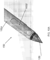
- an endoscopic cannula 100 of the present disclosure includes an elongated body 102 having a proximal end 104 and a distal end 106, terminating with a dissection tip 120.
- the cannula 100 further includes an cutting unit 150 disposed about the distal end 106 for sealing and cutting a blood vessel and a control handle 160 for controlling the cutting unit 150.
- the elongated body 102 is configured for passing extravascularly through an entry incision to a vessel harvesting site.
- the elongated body 102 may be sufficiently rigid axially along its length.
- the elongated body 102 may be made from a biocompatible material, such as, plastic material, elastomeric material, metallic material, shape memory material, composite material or any other materials that has the desired characteristics.
- the elongated body 102 may be provided with some flexibility to move radially or laterally from side to side depending on the application.
- the elongated body 102 of the cannula 100 may be solid.
- the endoscopic cannula 100 may include one or more lumen with lumena that accommodate advancing instruments or materials therethrough.
- the endoscopic cannula 100 may include an endoscopic lumen 103 through which an endoscope 116 may be advanced for visualizing procedures performed using the cannula 100.
- the endoscopic cannula 100 may include an adapter 114 at the proximal end 104 for advancing the endoscope 116 into the endoscopic cannula 100. Additional lumens of the cannula 100 are described below.
- the endoscopic cannula 100 may include a dissection tip 120 disposed at or about the distal end 106 of the endoscopic cannula 100.
- the viewing tip of the endoscope may be positioned inside the dissection tip 120.
- the dissection tip 120 may include an inner cavity in fluid communication with the endoscopic lumen 103 to enable the endoscope 116 to be advanced into the dissection tip 120.
- a chip-on-a-tip type of an endoscope may be integrated inside the dissection tip 120.
- the tip 120 may also be transparent to allow for endoscopic viewing through the tip 120 of the procedures performed using the cannula 100.
- the dissection tip 120 in some examples, may be provided with any shape as long as it facilitates endoscopic viewing therethrough, and allows for necessary control during tissue dissecting, i.e. separation. In the embodiments, the dissection tip is generally conical.
- the dissection tip 120 may include a generally flat shoulder 122, and a tapered section 124 which terminates in blunt end 126 for atraumatic separation of a vessel segment, being harvested from surrounding tissue, while minimizing or preventing tearing or puncturing of nearby vessels or tissue as the endoscopic cannula 100 is navigated along the vessel segment.
- blunt end 126 may be made relatively pointed to enhance advancement of the cannula 100.
- the dissection tip 120 may be cone shaped, and may be shaped at its distal end in a manner so as to minimize the negative effects of visual distortion or blinding at the center of the endoscopic view field when viewing through an endoscope inserted into the cannula 100, with a light source and camera system.
- Internal surface 121 of the dissection tip 120 may be tapered, with a relatively constant slope toward the distal end 126 of the dissection tip 120, terminating at an internal apex 123, which may be a sharp point, as shown in FIG. 1C .
- External surface 125 of the dissection tip 120 may also be tapered with a constant slope toward the distal end 126 of the dissection tip 120; however, at the distal end 126, a relatively rounded, blunt end may be formed to minimize tissue damage during dissection. As illustrated, at the distal end, the external surface 125 of the dissection tip 120 may be folded back on itself in a proximal direction to then terminate at an external apex 127, maintaining the blunt exterior surface and forming an indent in the distal end of the dissection tip 120. Both the internal apex 123 and the external apex 127 may be collinear with the central longitudinal axis of the cannula 100 and, thus, in some embodiments, the endoscope 116.
- the centers of the internal apex 123 and the external apex 127 are located on the central longitudinal axis of the cannula 100.
- the dissection tip 120 may be radially pliable, flexible or deformable so that the dissection tip may deflect slightly under exertion of force applied to the dissection tip 120.
- the dissection tip 120 is radially compressible so that the walls of the dissection tip 120 can deform under exertion of force normal to the tip surface.
- the dissection tip 120 may be formed from thin wall plastic material to enable the dissection tip to flex under load. Suitable materials include, but are not limited to, polycarbonate, polyethylene terephthalate glycol-modified (PETG), polyethylene terephthalate (PET) and other materials that provide enough optical clarity while allowing the dissection tip to flex under load.
- the dissection tip 120 may be provided with sufficient column strength in axial or longitudinal direction to allow dissection of the vessel from the surrounding connective tissue.
- blood vessels used in bypass grafting lie in the subcutaneous space, beneath the surface of the skin.
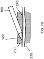
- the vessel 200 is composed of a main trunk 210, and branch vessels 220 that emanate from the vessel trunk 210, as shown in FIG. 2A .
- the vessel 200 and its branches 210 are encased in subcutaneous fatty connective tissue 230, and need to be dissected free of the surrounding fatty connective tissue 230 before the main vessel 200 may be harvested.
- the subcutaneous fat 230 is softer than skin, muscle, fascia or other connective tissues.
- the fatty connective tissue 230 forms an interface 240 with the vessel 200 that may be cleanly dissected; that is, there is a natural dissection plane between the outer layer of the vessel 200 (the adventitia), and the surrounding subcutaneous fat 230.
- FIG. 2B illustrates dissection of the main trunk 210 of the vessel 200 with the dissection tip 120 along the natural dissection plane, with the dissection tip 120 advanced along the adventitial surface of the vessel 200. Isolation of the vessel 200 from surrounding fatty connective tissue 230 along this plane, typically, does not require high dissection forces.
- the dissection tip may 120 be provided with sufficient column strength to dissect the vessel 200 from the surrounding tissue 230 along the natural dissection plane between them.
- the dissection tip 120 may catch the branch vessel 220 at a junction 250 between the branch vessel 220 and the main vessel 200.
- Application of excessive force with the dissection tip 220 may avulse the branch vessel and sever it from the trunk vessel, or may otherwise cause damage to the main vessel 200.
- the dissection tip 120 is provided with sufficient column strength to dissect the vessel 200 from the surrounding tissue 230 along the natural dissection plane between them, while being sufficiently pliable to deform or deflect from the branch vessel 220 with the application of increased force, to decrease the potential of trauma to the graft vessel during dissection around branch vessels.
- the rigidity of the dissection tip 120 may be varied from fully flexible to semi-rigid to rigid, in accordance with requirements of the procedure.
- the cannula 100 may further include one or more end-effectors for cauterizing or sealing and cutting a blood vessel, either a branch vessel or the main vessel.
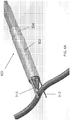
- the cutting unit 150 of the cannula 100 may include a first cutting member 302 and a second cutting member 304, each having a cutting portion 310, 312 extending from their respective distal ends.
- the first cutting member 302 and the second cutting member 304 are moveable in a longitudinal direction relative to the elongated body 102 of the cannula 100.
- the cutting portions 310, 312 are moved from an initial, retracted position during the dissection, in which the cutting portions 310, 312 are retracted substantially proximally of the dissection tip 120 not to interfere with the dissection, to an operational or extended position for sealing and cutting, in which the cutting portions 310, 312 may be advanced distally for the user to see the cutting portions and to provide enough capture length for the vessel.
- the cutting portions 310, 312 may at least partially extend beyond the dissection tip 120 to capture a blood vessel the cutting portions 310, 312.
- first cutting member 302 and the second cutting member 304 are rotatable relative to one another.
- the cutting portions 310, 312 may be moved from an open position when the cutting portions 310, 312 are apart or spaced away from one another to capture a blood vessel therebetween, as shown in FIG. 3B , to a closed position when the cutting portions 310, 312 are brought towards one another around the dissection tip 120 to seal and cut the blood vessel, as shown in FIG. 3C .
- the first cutting member 302 and the second cutting member 304 are configured so both cutting portions 310, 312 can be rotated circumferentially about the dissection tip 120 toward one another in both clockwise and counterclockwise direction depending on the location of the blood vessel to be captured between the cutting portions 310, 312.
- Such bi-directional, circumferential movement of the cutting portions 310, 312 may allow the user to operate on blood vessels on all sides of the cannula 100 to save time and reduce cannula manipulation during the procedure as the user does not need to be concerned about the orientation and position of the cannula 100 in relation to the blood vessel.
- it may reduce the potential for the cutting portions to twist the side branches, thereby exerting traction on the blood vessel and consequent damage to the graft.
- the bi-directional movement may also be more-intuative to the user and eliminates the need to remember which side is the active side for cautery and cutting.
- one of the cutting portions 310, 312 may be stationary and the other one may rotate in both clockwise and counterclockwise toward the stationary cutting portion for easier manipulation and visualization of the cutting portions 310, 312.
- the stationary cutting portion may also be moved to a desired orientation by moving the cannula 100.
- the cutting portions of the cutting members 302, 304 may generally be elliptical or blade-like with a rounded distal tip, but any other shape that enables the cutting and sealing of a blood vessel may also be used.
- one or both of the cutting portions 310, 312 may be energized, when needed, using various sources of energy, including, but not limited to, resistive heating, ultrasound heating, and bipolar or monopolar RF energy.
- the electrodes can be controlled independently of one another.
- the cutting portions 310, 312 may be made from a material such as metal that would enable the cutting portions 310, 312 themselves to be energized.
- energizing elements such as metal wires, may be disposed on the cutting portions 310, 312. When energized, the energizing elements may be brought in contact with the blood vessel by the cutting portions 310, 312 to seal the blood vessel.
- one or both of the cutting members 310, 312 may include protrusions for use as spot cautery.
- one or both of the cutting members 310, 312 may have a sharpened, thin edge for concentrated application of energy to the blood vessel. Such concentrated energy application may require less energy to be applied to the side branch, thereby minimizing extension of cauterizing energy from the side branch towards the main trunk of the blood vessel, and thus eliminating potential trauma to the blood vessel.
- one of the opposing edges 318, 320 of the cutting portions 310, 312 between which cutting occurs may have a leveled face while the other one may be a sharpened, thin or pointed so that the tissue is not cut in a scissor-like motion but with a thin edge against a flat surface.
- both edges of the cutting members 310 may be sharpened edges, while both edges of the cutting portion 312 may be flat, or vise versa.
- the cutting portions 310, 312 may have one sharp edge or blade edge and one flat edge with the sharp edge of one cutting portion facing the flat edge of the other cutting portion.
- the blood vessel may be both sealed and cut using energy, as described above. It should of course be understood that, in some embodiments, the opposing edges the opposing edges 318, 320 of the cutting portions 310, 312 may both be sharpened so the tissue is cut in a scissor-like manner.
- the cutting members 302, 304 may be substantially u-shaped and disposed in the same plane relative to the cannula body 102.
- the cutting members 302, 304 may include respective cutouts and fingers 314, 316 along the edges to enable circumferential movement of the cutting members 302, 304 relative to one another.
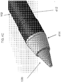
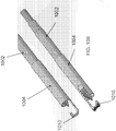
- the cutting members 302, 304 may be substantially tubular and be disposed in different planes of the cannula body 102. As shown in FIG. 4A , in some embodiments, the cutting member 304 may be concentrically disposed inside within the cutting member 302. Referring to FIG. 4B , in some embodiments, the elongated body 102 of the cannula 100 may be constructed of a series of coaxial tubes, both metal and plastic, that may act as the structural main shaft, the electrical conductive and insulative paths, and the end-effectors, i.e. cutting portions 310, 312.
- the innermost layer may be the inner sheath 402 (plastic) defining an internal lumen 403.
- the inner sheath 402 may be followed outwardly by the inner electrode tube 404 (metal), middle sheath 406 (plastic), outer electrode tube 408 (metal) and outer sheath 410 (plastic), and finally a shrink jacket 412.
- the electrical insulation may be provided using non-conductive coatings or similar means.
- the electrodes 404, 408 may be coated with polyvinyldyne flouride (PVDF), but other non-conductive coating may also be used.
- PVDF polyvinyldyne flouride
- the inner electrode tube 404 and the outer electrode tube 408 may be used to form the first cutting member 302 and the second cutting member 304, with the cutting portions 310, 312 being formed at the distal ends of the inner electrode tube 404 and the outer electrode tube 408.
- the inner electrode tube 404 and the outer electrode tube 408 may be slidable in the longitudinal direction relative to the cannula 100 and rotatable relative to one another. Further, because the cutting portions 310, 312 are formed from the inner electrode tube 404 and the outer electrode tube 408, the cutting portions 310, 312 can be easily energized through the inner electrode 404 and the outer electrode 408.
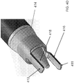
- the cutting portion formed from the inner electrode tube 404 may be bent out of the plane of the inner electrode 404 to enable it to rotate along the same axis and be co-radial with the cutting portion formed in the outer electrode 408 (i.e. outer cutting portion 413).
- the inner cutting portion 411 may have a flat face 416 on either side of the inner cutting portion, while the outer cutting portion 413 may have a sharpened or blade edge 418 on both sides, or vice versa.
- each cutting portion 411, 413 may have one sharpened edge and one flat edge, with the flat edge of one cutting portion facing the sharpened edge of the other cutting portion.
- the dissection tip 120 may be connected to the inner sheath 402 to enable the advancement of the endoscope 116 into the dissection tip though the internal lumen 403.
- a sleeve 414 may be used to protect tissue from damage during dissection by smoothing the geometry between the dissection tip 120 and the cannula body 102.
- the distal end of the sleeve 414 may be left unattached to the dissection tip 120 to allow the cutting portions 312, 314 to be advanced distally through the sleeve 414, as shown in FIG. 4D .
- the sleeve 414 may be made of a flexible material so during dissection the sleeve 414 would comply with the dissection tip creating a smooth transition and also a tight seal to prevent tissue or bodily fluids from entering the cannula 100.
- a flexible sleeve would be able to deflect and expand to allow the cutting portions 312, 314 to be advanced out distally though the sleeve 414.
- the surface of the sleeve may be coated with a lubricious substance to make the extension of the cutting portions 312, 314 through the sleeve 414 easier and smoother by decreasing friction between the cutting portions 312, 314 and the sleeve 414.
- the thin-walled shrink tube 412 may be placed over the outer surface of the cannula body for aesthetic purposes and to assist in securing the transition.
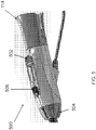
- FIG. 5 illustrates an embodiment of the control handle 160 for controlling the cutting members 310, 312.
- the control handle 160 may include a translation control 502 for advancing and retracting the cutting members 310, 312.
- the control handle further includes a rotation control 504 for rotating the cutting members with respect to one another.
- the control handle 160 includes an energy control 506 for supplying energy (such as bipolar RF energy) to the cutting portions 310, 312.
- the adapter 114 may be located at the proximal end of the control handle 500 for advancing the endoscope 116 into the endoscopic cannula 100.
- an initial incision may be made in conventional manner to expose the target vessel (e.g., the saphenous vein).
- the cannula 100 may be inserted into the incision and guided to the target vessel.
- the cannula 100 may include a smooth tubular sheath around the elongated body 102 for sealing the cannula 102 within the port through which the cannula 102 is introduced into the patient.
- the cannula 100 may then be advanced substantially along the target vessel to dissect the target vessel from the surrounding tissue.
- the cannula 100 may be introduced through a sealable port used to seal the incision to allow insufflation of the space created by the dissection of the target vessel from surrounding tissues.
- the cutting portions 310, 312 of the cutting elements 302, 304 may be kept in a retracted position so not to interfere with tissue dissection until a branch vessel is encountered. At that point, the cutting portions 310, 312 may be advanced beyond the dissection tip 120, as described above, to capture, seal and cut the branch vessel.
- the cutting portions 310, 312 may be moved from a retracted position, as shown in FIGS. 6A-6B , in the distal direction beyond the dissection tip 120 by advancing the translational control 504 on the handle to its distal position, as shown in FIGS. 6C-6D .
- the cutting portions 310, 312 may be advanced out together and enter into the field of view of the endoscope in the dissection tip 120.
- the cutting portions 310, 312 may be rotated with respect to one another using the rotation control 504, as shown in FIGS. 6E-6F , for sealing and cutting the branch vessel.
- the cutting portions 310, 312 may be rotated around the dissection tip 120 in a circular arc motion.
- the endoscopic cannula 100 may be positioned such that the target branch vessel may lay across one of the cutting portions 310, 312, regardless of orientation of the branch vessel in relation to the main blood vessel to be harvested.
- the endoscopic cannula 100 may be designed such that the user can place the endoscopic cannula 100 and the cutting portions 310, 312 as far away from the target main vessel as possible to avoid injury to the main vessel. Once in position, the user may rotate one of the cutting portions 310, 312 toward the other one until the branch vessel is captured. If positioned properly, the rotation is preferably always away from the main vessel, thus increasing and further maximizing the potential negative effects of lateral thermal spread.
- the user may depresses the energy control 508 button to transfer the energy into the tributary to seal the vessel.
- the user may continue to advance the rotation control 504 until the cutting portions 310, 312 transect the branch vessel.
- the user may then retract the cutting portions 312, 314 with the translation control 502 and advance the device to the next branch vessel until all tributaries have been successfully ligated and transected.
- the cannula 100 may be advanced forward until the next branch vessel is encountered, at which point the branch vessel may be sealed and severed using the cutting unit 300. Once all branch vessels along a desired length of the target vessel have been sealed and severed, the cannula 100 may be used to seal and cut the target vessel according to procedure similar to the procedure used to cut and seal the branch vessels. Alternatively, the cannula 100 may be withdrawn, and another surgical device may be used to seal and cut the main vessel.
- the cannula 100 of the present disclosure may allow vessel sealing and cutting to be performed in a small cavity. Accordingly, when using the cannula 100 of the present disclosure there may not be a need to maintain the perivascular cavity in an expanded state and thus the procedure may be performed without gas insufflation of the perivascular cavity.
- the transparent dissection tip 120 can deflect a vessel to one side, so that the members of the cutting unit can capture the vessel, while maintaining visualization of all components in a collapsed tissue tunnel. Vessel harvesting in a small or collapsed cavity may be useful in anatomic situations characterized by vessel tortuosity, such as the internal mammary artery and vein. Harvesting without gas insufflation may also be beneficial to the graft.
- the carbonic acid environment of a cavity maintained by carbon dioxide gas insufflation may be detrimental to the graft vessel.
- a lower pH atmosphere surrounding the vessel may alter the cellular viability of the graft, potentially leading to early graft failure.
- Positive pressure produced by gas insufflation may also collapse the vessel, causing hemostasis, and may increase the potential for intraluminal clot formation. Presence of intraluminal clot may cause graft thrombosis and early graft failure.
- the cutting unit 150 may include a first member 702 and a second member 704.
- the first member 702 and second member 704 may be translatable relative to the dissection tip 120 from a proximal position, during the dissection, to a more distal position to capture, seal and cut the blood vessel.
- the first member 702 and second member 704 may also be moveable relative to one another so the first member 702 and second member 704 can be space away from one another capture a blood vessel therebetween and then may be compressed against one another to seal and cut the blood vessel.
- first member 702 and second member 704 may be mounted on one or more actuating rods for advancing and retracting. It should, of course, be understood that other mechanisms for translating the first member 702 and second member 704 relative to the dissection tip 120 and one another may be employed.
- the first member 702 may include four circumferentially-disposed proximal electrode segments 706 for bipolar RF cutting.
- the proximal electrode segments may be connected by 0.508 mm (0.020") conductor.
- the second member 704 may include two circumferentially-disposed distal electrode segments 708 for bipolar RF cutting.
- the distal electrode segments may be connected by 0.508 mm (0.020") conductor.
- the second member 704 may include two segments 710 for resistive heat cautery 706 disposed distally of the distal electrode segments, and a distal ring electrode 712 for monopolar cautery.
- the actuating rods may be employed to energize the electrodes 706-712.
- the cutting unit 150 may include a first member 802 and a second member 804.
- the first member 802 and the second member 804 are translatable relative to the dissection tip and one another, as described above.
- the three electrodes 708, 710, and 712 of the second member 704 are combined into one solid ring.
- bipolar mode the only one side of the ring may work with active proximal segment.
- monopolar mode the entire ring may work with outside returned electrode.
- Two large cross-section conductors may also replace four electrode segments, two for RF cutting and two for resistive heat cautery, which may increase rigidity of the distal structure.
- the four electrodes 706 of the first member 702 can also be combined into two hemispheric electrodes 806, which can be individually controlled. In this manner, only two larger cross-section conductors 808 may be used instead of four small ones, as in the cutting unit illustrated in FIGS. 7A and 7B . Rigidity of the proximal structure may also increase by combining the four electrodes into two.
- the cutting unit 150 may include a first member 902 having a proximal electrode 916 for bipolar RF cutting.
- the cutting unit 150 may also include a second member 904 having a distal electrode 918 for bipolar RF cutting.
- the cutting unit 150 may further include an electrode 914 for monopolar spot cautery disposed over the dissection tip 120.
- the first member 902 and the second member 904 may be made of a conductive material, with optional coating, and the electrodes 914, 916, 918 may be energized through the cutting member 902, 904.
- the first member 902 and the second member 904 may be tubular, with the first member 902 slidably disposed relative to the second member 904 to enable the first member 902 and the second member 904 to be biased relative to one another in a longitudinal direction.
- the first member 902 and the second member 904 may be move in a distal direction between an inactive position proximal of the dissection tip 120, as shown in FIG. 9A , and an active position in the field of view of the endoscope, as shown in FIG. 9B and FIG. 9C , for capturing, cutting and sealing the blood vessel.
- the second member 904 may include one or more hooks 906 at a distal region of the second member 904.
- the hook 906 may be configured to capture the branch vessel, as shown in FIG. 9B .
- the second member 904 may include two hooks 910 and 912, in a spaced relation to one another, so that the branch vessel may be contacted, at a minimum, by one of the hooks.
- the cannula 100 may be advanced to a vessel with the first member 902 and the second member 904 of the cutting unit 150 positioned proximally to the dissection tip 120.
- the second member 904 may be extended in the distal direction to capture the branch vessel by the hook of the second member 904.
- Spot cautery may also be performed in this position, as desired, by a spot cautery electrode 914.
- the first member 902 may be advanced to pinch the branch vessel between the electrodes 916, 918 of the first member 902 and the second member 904, and the RF current may be turned on for sealing and cutting the branch vessel captured in the cutting unit 150.
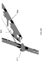
- FIG. 10A and FIG. 10B illustrate yet another example of the cutting unit 150 having a first member 1002 and a second member 1004.
- the second member 1004 may include only a single hook 1010 on one side of the second member 1004, as compared to two hooks 910, 912 on the second member 904. Removing one of hooks may improve visualization of the procedure by the endoscope 116 disposed within the cannula 100. Otherwise, the structure and operations of this cutting unit 150 may be similar to those of the cutting unit 150 disclosed in FIGS. 9A-9C .
- all electrodes can be energized using various sources of energy, including, but not limited to, resistive heating, ultrasound heating, and bipolar or monopolar RF energy.
- the electrodes can be controlled independently of one another.
- the electrodes may be insulated with an insulating coating or insulating sheath.
Claims (15)
- Chirurgische Vorrichtung, umfassend:einen länglichen Körper (102) mit einem proximalen Ende (104) und einem distalen Ende (106);eine am distalen Ende des länglichen Körpers angeordnete Spitze (120), wobei die Spitze eine konische Form aufweist und einen inneren Hohlraum zum Aufnehmen eines Endoskops (116) definiert; undeine Schneideeinheit (150) mit einem ersten Schneidabschnitt (310) und einem zweiten Schneidabschnitt (312), wobei der erste Schneidabschnitt und der zweite Schneidabschnitt in einer Längsrichtung relativ zum länglichen Körper von einer zurückgezogenen Position, die im Wesentlichen proximal zur Spitze ist, zu einer über die Spitze verlängerten Position bewegt werden können, um ein Blutgefäß zwischen dem ersten Schneidabschnitt und dem zweiten Schneidabschnitt zu erfassen, und in Umfangsrichtung um die Spitze zueinander gedreht werden können, um das erfasste Blutgefäß zu schneiden.
- Chirurgische Vorrichtung nach Anspruch 1, wobei der erste Schneidabschnitt (310) und der zweite Schneidabschnitt (312) konfiguriert sind, um zum Dichten, Schneiden oder beides des erfassten Blutgefäßes mit Energie versorgt zu werden.
- Chirurgische Vorrichtung nach Anspruch 1, wobei der erste Schneidabschnitt (310) eine geschärfte Kante (318) aufweist und eine Kante (320) des zweiten Schneidabschnitts (312), die zur geschärften Kante des ersten Schneidabschnitts zeigt, eben ist.
- Chirurgische Vorrichtung nach Anspruch 1, wobei der erste Schneidabschnitt (310) stationär ist und der zweite Schneidabschnitt (312) um die Spitze (120) zum ersten Schneidabschnitt gedreht werden kann.
- Chirurgische Vorrichtung nach Anspruch 1, wobei der zweite Schneidabschnitt (312) um die Spitze (120) bidirektional gedreht werden kann.
- Chirurgische Vorrichtung nach Anspruch 1, wobei der längliche Körper ein erstes Schneidelement (302) und ein zweites Schneidelement (304) umfasst und der erste Schneidabschnitt (310) und der zweite Schneidabschnitt (312) an jeweiligen distalen Enden des ersten Schneidelements und des zweiten Schneidelements geformt sind.
- Chirurgische Vorrichtung nach Anspruch 6, wobei das erste Schneidelement (302) und das zweite Schneidelement (304) konfiguriert sind, um HF-Energie zum ersten Schneidabschnitt (310) bzw. zum zweiten Schneidabschnitt (312) zu leiten.
- Chirurgische Vorrichtung nach Anspruch 7, wobei eine isolierende Beschichtung zwischen dem ersten Schneidelement (302) und dem zweiten Schneidelement (304) angeordnet ist.
- Chirurgische Vorrichtung nach Anspruch 1, ferner umfassend eine Hülse (414) mit einem an einer äußeren Oberfläche des länglichen Körpers befestigten proximalen Ende und einer die Spitze (120) in Eingriff nehmenden distalen Spitze, wobei die distale Spitze nicht an der Spitze befestigt ist, um dem ersten Schneidabschnitt (310) und dem zweiten Schneidabschnitt (312) ein Vorrücken durch die Hülse zu ermöglichen.
- Chirurgische Vorrichtung nach Anspruch 1, wobei die Spitze:einen inneren Scheitel (123); undeinen eingedrückten äußeren Scheitel (127) an einem distalen Ende (126) der Spitze aufweist, wobei der innere Scheitel und der äußere Scheitel kolinear mit der Mittelachse des länglichen Körpers sind, um die Visualisierung durch die Spitze (120) zu verbessern.
- Chirurgische Vorrichtung nach Anspruch 10, wobei sich der innere Hohlraum (121) in einer distalen Richtung verjüngt, um den inneren Scheitel (123) zu formen.
- Chirurgische Vorrichtung nach Anspruch 11, wobei sich eine äußere Oberfläche (125) der Spitze (120) zur distalen Spitze verjüngt und an der distalen Spitze gefaltet ist, um den eingedrückten äußeren Scheitel (127) zu formen.
- Chirurgische Vorrichtung nach Anspruch 6, wobei das erste Schneidelement (302) und das zweite Schneidelement (304) relativ zueinander gedreht werden können.
- Chirurgische Vorrichtung nach Anspruch 1, wobei:der erste Schneidabschnitt (310) elliptisch mit einer abgerundeten distalen Spitze ist; undder zweite Schneidabschnitt (312) elliptisch mit einer abgerundeten distalen Spitze ist.
- Chirurgische Vorrichtung nach Anspruch 1, wobei: der erste Schneidabschnitt (310) klingenartig ist und der zweite Schneidabschnitt (312) klingenartig ist.
Applications Claiming Priority (3)
| Application Number | Priority Date | Filing Date | Title |
|---|---|---|---|
| US201361782034P | 2013-03-14 | 2013-03-14 | |
| US201361833814P | 2013-06-11 | 2013-06-11 | |
| PCT/US2014/018737 WO2014158613A1 (en) | 2013-03-14 | 2014-02-26 | Unitary endoscopic vessel harvesting devices |
Publications (3)
| Publication Number | Publication Date |
|---|---|
| EP2967629A1 EP2967629A1 (de) | 2016-01-20 |
| EP2967629A4 EP2967629A4 (de) | 2017-03-22 |
| EP2967629B1 true EP2967629B1 (de) | 2019-05-29 |
Family
ID=51621555
Family Applications (1)
| Application Number | Title | Priority Date | Filing Date |
|---|---|---|---|
| EP14773921.3A Active EP2967629B1 (de) | 2013-03-14 | 2014-02-26 | Einheitliche endoskopische gefässentnahmevorrichtungen |
Country Status (5)
| Country | Link |
|---|---|
| US (3) | US9498246B2 (de) |
| EP (1) | EP2967629B1 (de) |
| JP (1) | JP6283091B2 (de) |
| CN (1) | CN105188575B (de) |
| WO (1) | WO2014158613A1 (de) |
Families Citing this family (14)
| Publication number | Priority date | Publication date | Assignee | Title |
|---|---|---|---|---|
| EP2967629B1 (de) | 2013-03-14 | 2019-05-29 | Saphena Medical, Inc. | Einheitliche endoskopische gefässentnahmevorrichtungen |
| US9814481B2 (en) | 2013-03-14 | 2017-11-14 | Saphena Medical, Inc. | Unitary endoscopic vessel harvesting devices |
| JP6596019B2 (ja) * | 2014-12-04 | 2019-10-23 | テルモ株式会社 | 血管剥離デバイス |
| US9943328B2 (en) * | 2015-04-28 | 2018-04-17 | Saphena Medical, Inc. | Unitary endoscopic vessel harvesting devices with an elastic force |
| JP7166761B2 (ja) * | 2015-06-17 | 2022-11-08 | サフィナ・メディカル・インコーポレイテッド | 単一内視鏡血管採取装置 |
| US10045809B2 (en) * | 2015-08-05 | 2018-08-14 | Terumo Cardiovascular Systems Corporation | Endoscopic vessel harvester with blunt and active dissection |
| US10709430B2 (en) * | 2015-10-13 | 2020-07-14 | Terumo Kabushiki Kaisha | Vein dissecting device and method |
| JP6594800B2 (ja) * | 2016-02-26 | 2019-10-23 | テルモ株式会社 | 切断デバイス、及びこの切断デバイスを有する剥離システム |
| CN105963013B (zh) * | 2016-06-13 | 2019-01-04 | 北京米道斯医疗器械有限公司 | 一种低温内窥镜血管采集装置及方法 |
| US20200222589A1 (en) * | 2017-05-30 | 2020-07-16 | Adeka Corporation | Method for producing decellularized material for transplantation and graft composition consisting of biocompatible material including said material |
| US11432839B2 (en) * | 2018-01-12 | 2022-09-06 | Maquet Cardiovascular Llc | Vessel harvesting apparatus and method |
| US10813659B2 (en) | 2018-03-22 | 2020-10-27 | Spiration, Inc. | Rotational tissue cutting device |
| US11399819B2 (en) | 2018-07-11 | 2022-08-02 | Lsi Solutions, Inc. | Percutaneous sub-xiphoid lifting device and methods thereof |
| WO2020061328A1 (en) | 2018-09-21 | 2020-03-26 | Saphena Medical, Inc. | Surgical insufflation and irrigation conduits and methods for use |
Family Cites Families (88)
| Publication number | Priority date | Publication date | Assignee | Title |
|---|---|---|---|---|
| JPS6283091A (ja) | 1985-10-08 | 1987-04-16 | Toshiba Corp | 塩素注入装置 |
| JPS6486862A (en) | 1987-09-28 | 1989-03-31 | Keiichi Nishibashi | Instant carbonated beverage |
| US5676636A (en) | 1994-07-22 | 1997-10-14 | Origin Medsystems, Inc. | Method for creating a mediastinal working space |
| US5373840A (en) | 1992-10-02 | 1994-12-20 | Knighton; David R. | Endoscope and method for vein removal |
| US5980549A (en) * | 1995-07-13 | 1999-11-09 | Origin Medsystems, Inc. | Tissue separation cannula with dissection probe and method |
| US5591183A (en) | 1995-04-12 | 1997-01-07 | Origin Medsystems, Inc. | Dissection apparatus |
| US5728123A (en) | 1995-04-26 | 1998-03-17 | Lemelson; Jerome H. | Balloon actuated catheter |
| US5556408A (en) | 1995-04-27 | 1996-09-17 | Interventional Technologies Inc. | Expandable and compressible atherectomy cutter |
| US5695514A (en) | 1995-07-13 | 1997-12-09 | Guidant Corporation | Method and apparatus for harvesting blood vessels |
| US7384423B1 (en) * | 1995-07-13 | 2008-06-10 | Origin Medsystems, Inc. | Tissue dissection method |
| US5797946A (en) | 1995-07-13 | 1998-08-25 | Origin Medsystems, Inc. | Method for arterial harvest and anastomosis for coronary bypass grafting |
| US7001404B1 (en) | 1995-07-13 | 2006-02-21 | Origin Medsystems, Inc. | Tissue separation cannula and method |
| US5968065A (en) | 1995-07-13 | 1999-10-19 | Origin Medsystems, Inc. | Tissue separation cannula |
| US5772576A (en) | 1995-12-11 | 1998-06-30 | Embro Vascular L.L.C. | Apparatus and method for vein removal |
| AU719712B2 (en) * | 1996-01-24 | 2000-05-18 | Origin Medsystems, Inc. | Tissue separation cannula with dissection probe and method |
| US20030229366A1 (en) | 1996-02-02 | 2003-12-11 | Transvascular, Inc. | Implantable lumen occluding devices and methods |
| US5810805A (en) | 1996-02-09 | 1998-09-22 | Conmed Corporation | Bipolar surgical devices and surgical methods |
| US6019771A (en) * | 1996-12-02 | 2000-02-01 | Cardiothoracic Systems, Inc. | Devices and methods for minimally invasive harvesting of a vessel especially the saphenous vein for coronary bypass grafting |
| US5984937A (en) | 1997-03-31 | 1999-11-16 | Origin Medsystems, Inc. | Orbital dissection cannula and method |
| US5921919A (en) | 1997-05-30 | 1999-07-13 | Origin Medsystems, Inc. | Perivascular self-retaining retractor and method |
| US5873889A (en) | 1997-08-08 | 1999-02-23 | Origin Medsystems, Inc. | Tissue separation cannula with dissection probe and method |
| US6102909A (en) | 1997-08-26 | 2000-08-15 | Ethicon, Inc. | Scissorlike electrosurgical cutting instrument |
| US5891141A (en) * | 1997-09-02 | 1999-04-06 | Everest Medical Corporation | Bipolar electrosurgical instrument for cutting and sealing tubular tissue structures |
| US6402720B1 (en) | 1997-12-22 | 2002-06-11 | Cordis Corporation | Balloon catheter with elongated flexible tip |
| US5916233A (en) | 1998-03-05 | 1999-06-29 | Origin Medsystems, Inc. | Vessel harvesting method and instrument including access port |
| US5895353A (en) | 1998-06-22 | 1999-04-20 | Origin Medsystems, Inc. | Vessel isolating retractor cannula and method |
| US6830546B1 (en) | 1998-06-22 | 2004-12-14 | Origin Medsystems, Inc. | Device and method for remote vessel ligation |
| US6162173A (en) | 1998-06-22 | 2000-12-19 | Origin Medsystems, Inc. | Device and method for remote vessel ligation |
| US6406425B1 (en) | 1998-06-22 | 2002-06-18 | Origin Medasystems | Cannula-based irrigation system and method |
| US6176825B1 (en) | 1998-06-22 | 2001-01-23 | Origin Medsystems, Inc. | Cannula-based irrigation system and method |
| US6976957B1 (en) | 1998-06-22 | 2005-12-20 | Origin Medsystems, Inc. | Cannula-based surgical instrument and method |
| US7326178B1 (en) | 1998-06-22 | 2008-02-05 | Origin Medsystems, Inc. | Vessel retraction device and method |
| US7695470B1 (en) | 1998-08-12 | 2010-04-13 | Maquet Cardiovascular Llc | Integrated vessel ligator and transector |
| US7534243B1 (en) | 1998-08-12 | 2009-05-19 | Maquet Cardiovascular Llc | Dissection and welding of tissue |
| EP0979635A2 (de) | 1998-08-12 | 2000-02-16 | Origin Medsystems, Inc. | Gewebedissektor |
| US7485092B1 (en) | 1998-08-12 | 2009-02-03 | Maquet Cardiovascular Llc | Vessel harvesting apparatus and method |
| US6030406A (en) | 1998-10-05 | 2000-02-29 | Origin Medsystems, Inc. | Method and apparatus for tissue dissection |
| US6042538A (en) * | 1998-11-18 | 2000-03-28 | Emory University | Device for endoscopic vessel harvesting |
| WO2000040160A2 (en) | 1999-01-08 | 2000-07-13 | Origin Medsystems, Inc. | Combined vessel dissection and transection device and method |
| US6860892B1 (en) | 1999-05-28 | 2005-03-01 | General Surgical Innovations, Inc. | Specially shaped balloon device for use in surgery and method of use |
| US6569082B1 (en) | 1999-08-10 | 2003-05-27 | Origin Medsystems, Inc. | Apparatus and methods for cardiac restraint |
| US7264587B2 (en) | 1999-08-10 | 2007-09-04 | Origin Medsystems, Inc. | Endoscopic subxiphoid surgical procedures |
| US7398781B1 (en) | 1999-08-10 | 2008-07-15 | Maquet Cardiovascular, Llc | Method for subxiphoid endoscopic access |
| US6607547B1 (en) | 1999-08-25 | 2003-08-19 | Origin Medsystems, Inc. | Longitudinal dilator and method |
| US6706052B1 (en) | 1999-08-10 | 2004-03-16 | Origin Medsystems, Inc. | Longitudinal dilator and method |
| US6287304B1 (en) * | 1999-10-15 | 2001-09-11 | Neothermia Corporation | Interstitial cauterization of tissue volumes with electrosurgically deployed electrodes |
| US6428539B1 (en) | 2000-03-09 | 2002-08-06 | Origin Medsystems, Inc. | Apparatus and method for minimally invasive surgery using rotational cutting tool |
| US6471638B1 (en) | 2000-04-28 | 2002-10-29 | Origin Medsystems, Inc. | Surgical apparatus |
| JP2004501711A (ja) * | 2000-05-16 | 2004-01-22 | タウト インコーポレイテッド | トロカールアセンブリ用穿刺用先端部 |
| US6951568B1 (en) | 2000-07-10 | 2005-10-04 | Origin Medsystems, Inc. | Low-profile multi-function vessel harvester and method |
| US6811546B1 (en) | 2000-08-25 | 2004-11-02 | Origin Medsystems, Inc. | Endoscopic surgical access port and method |
| US6673087B1 (en) | 2000-12-15 | 2004-01-06 | Origin Medsystems | Elongated surgical scissors |
| AU2002345954B2 (en) | 2001-06-26 | 2008-02-28 | Covidien Lp | Conduit harvesting instrument and method |
| WO2003013367A2 (en) * | 2001-08-10 | 2003-02-20 | General Surgical Innovations Inc. | Vascular harvesting tool and methods |
| US6749609B1 (en) | 2002-02-05 | 2004-06-15 | Origin Medsystems, Inc. | Electrocautery scissors |
| US6979290B2 (en) | 2002-05-30 | 2005-12-27 | The Board Of Trustees Of The Leland Stanford Junior University | Apparatus and methods for coronary sinus access |
| US7270664B2 (en) * | 2002-10-04 | 2007-09-18 | Sherwood Services Ag | Vessel sealing instrument with electrical cutting mechanism |
| US7931590B2 (en) | 2002-10-29 | 2011-04-26 | Maquet Cardiovascular Llc | Tissue stabilizer and methods of using the same |
| US7993285B2 (en) | 2002-11-05 | 2011-08-09 | Boston Scientific Scimed, Inc. | Medical device having flexible distal tip |
| US7556633B2 (en) * | 2004-03-01 | 2009-07-07 | Terumo Corporation | Method and apparatus for endoscopic dissection of blood vessels |
| US7887558B2 (en) | 2004-09-28 | 2011-02-15 | Maquet Cardiovascular Llc | Modular vessel harvesting system and method |
| US20060095056A1 (en) * | 2004-10-29 | 2006-05-04 | Peter Douglas | Device for incising a blood vessel |
| US7918848B2 (en) | 2005-03-25 | 2011-04-05 | Maquet Cardiovascular, Llc | Tissue welding and cutting apparatus and method |
| US8197472B2 (en) | 2005-03-25 | 2012-06-12 | Maquet Cardiovascular, Llc | Tissue welding and cutting apparatus and method |
| US8083664B2 (en) | 2005-05-25 | 2011-12-27 | Maquet Cardiovascular Llc | Surgical stabilizers and methods for use in reduced-access surgical sites |
| US20060271032A1 (en) | 2005-05-26 | 2006-11-30 | Chin Albert K | Ablation instruments and methods for performing abalation |
| US8080009B2 (en) * | 2005-07-01 | 2011-12-20 | Halt Medical Inc. | Radio frequency ablation device for the destruction of tissue masses |
| US9770230B2 (en) * | 2006-06-01 | 2017-09-26 | Maquet Cardiovascular Llc | Endoscopic vessel harvesting system components |
| EP2476384B1 (de) | 2006-11-22 | 2015-11-04 | Applied Medical Resources Corporation | Trokarkanüle mit atraumatischer Spitze |
| US8372096B2 (en) * | 2007-02-23 | 2013-02-12 | Terumo Cardiovascular Systems | Ring vessel dissector/harvester device |
| US8414480B2 (en) | 2007-03-22 | 2013-04-09 | Maquet Cardiovascular Llc | Methods and devices for reducing reflection-illuminated artifacts |
| US20090306690A1 (en) | 2008-06-05 | 2009-12-10 | Cardiovascular Systems, Inc. | Abrasive nose cone with expandable cutting and sanding region for rotational atherectomy device |
| JP5709747B2 (ja) | 2008-07-28 | 2015-04-30 | スパイン ビュー, インコーポレイテッド | 直接的可視化を有する貫通部材 |
| US9364259B2 (en) | 2009-04-21 | 2016-06-14 | Xlumena, Inc. | System and method for delivering expanding trocar through a sheath |
| US8676636B2 (en) | 2009-04-22 | 2014-03-18 | Parkpod Gmbh | System for managing electric energy grid-vehicle exchange devices |
| US8657818B2 (en) | 2009-08-21 | 2014-02-25 | Maquet Cardiovascular Llc | Single handled endoscopic vessel harvesting system with rotation control |
| US20120232342A1 (en) | 2009-10-15 | 2012-09-13 | Boris Reydel | Disposable and reusable comlex shaped see-through endoscope |
| EP2364653A1 (de) | 2010-03-11 | 2011-09-14 | Tyco Healthcare Group LP | Einführvorrichtung und Verfahren dafür |
| WO2011130399A1 (en) * | 2010-04-13 | 2011-10-20 | Surgiquest, Incorporated | Visualization trocar |
| DE102010028167A1 (de) | 2010-04-23 | 2011-10-27 | W.O.M. World Of Medicine Ag | Invasives Instrument zur Bearbeitung von Gefäßen und ein Verfahren |
| WO2012040201A1 (en) | 2010-09-20 | 2012-03-29 | Pavilion Medical Innovations | Endoscopic Cannula and Methods of Using Same |
| DE102011075781A1 (de) | 2011-05-13 | 2012-11-15 | Karl Storz Gmbh & Co. Kg | Elektrochirurgisches Instrument |
| US20130197299A1 (en) | 2011-12-23 | 2013-08-01 | Albert K. Chin | Unitary Endoscopic Vessel Harvesting Devices |
| EP2967629B1 (de) | 2013-03-14 | 2019-05-29 | Saphena Medical, Inc. | Einheitliche endoskopische gefässentnahmevorrichtungen |
| US9814481B2 (en) | 2013-03-14 | 2017-11-14 | Saphena Medical, Inc. | Unitary endoscopic vessel harvesting devices |
| US9943328B2 (en) | 2015-04-28 | 2018-04-17 | Saphena Medical, Inc. | Unitary endoscopic vessel harvesting devices with an elastic force |
| JP7166761B2 (ja) | 2015-06-17 | 2022-11-08 | サフィナ・メディカル・インコーポレイテッド | 単一内視鏡血管採取装置 |
| EP3310277B1 (de) | 2015-06-17 | 2021-05-26 | Saphena Medical, Inc. | Vorrichtung zur einheitlichen endoskopischen gefässentnahme |
-
2014
- 2014-02-26 EP EP14773921.3A patent/EP2967629B1/de active Active
- 2014-02-26 JP JP2016500439A patent/JP6283091B2/ja active Active
- 2014-02-26 CN CN201480008014.6A patent/CN105188575B/zh active Active
- 2014-02-26 WO PCT/US2014/018737 patent/WO2014158613A1/en active Application Filing
- 2014-02-26 US US14/190,873 patent/US9498246B2/en active Active
-
2016
- 2016-10-06 US US15/287,084 patent/US10537353B2/en active Active
-
2018
- 2018-11-09 US US16/185,215 patent/US20190076161A1/en active Pending
Non-Patent Citations (1)
| Title |
|---|
| None * |
Also Published As
| Publication number | Publication date |
|---|---|
| US20170020546A1 (en) | 2017-01-26 |
| EP2967629A4 (de) | 2017-03-22 |
| US9498246B2 (en) | 2016-11-22 |
| US20190076161A1 (en) | 2019-03-14 |
| CN105188575B (zh) | 2018-03-02 |
| CN105188575A (zh) | 2015-12-23 |
| WO2014158613A1 (en) | 2014-10-02 |
| JP2016514016A (ja) | 2016-05-19 |
| JP6283091B2 (ja) | 2018-02-21 |
| US20140296847A1 (en) | 2014-10-02 |
| EP2967629A1 (de) | 2016-01-20 |
| US10537353B2 (en) | 2020-01-21 |
Similar Documents
| Publication | Publication Date | Title |
|---|---|---|
| US11751896B2 (en) | Unitary endoscopic vessel harvesting devices | |
| US10537353B2 (en) | Unitary endoscopic vessel harvesting devices | |
| US10874415B2 (en) | Unitary endoscopic vessel harvesting devices | |
| US20130197299A1 (en) | Unitary Endoscopic Vessel Harvesting Devices | |
| EP3087927B1 (de) | Einheitliches endoskopisches entfernen von gefässen mit federkraft | |
| US9119900B2 (en) | Unitary endoscopic vessel harvesting devices | |
| US20170035487A1 (en) | Endoscopic vessel harvester with blunt and active dissection | |
| EP3310277B1 (de) | Vorrichtung zur einheitlichen endoskopischen gefässentnahme | |
| US10058345B2 (en) | Single-pass endoscopic vessel harvesting | |
| US20230404611A1 (en) | Unitary Endoscopic Vessel Harvesting Devices | |
| US20200345408A1 (en) | Unitary endoscopic vessel harvesting devices with a visual cue to identify orientation of cutting elements | |
| US10045809B2 (en) | Endoscopic vessel harvester with blunt and active dissection |
Legal Events
| Date | Code | Title | Description |
|---|---|---|---|
| PUAI | Public reference made under article 153(3) epc to a published international application that has entered the european phase |
Free format text: ORIGINAL CODE: 0009012 |
|
| 17P | Request for examination filed |
Effective date: 20150916 |
|
| AK | Designated contracting states |
Kind code of ref document: A1 Designated state(s): AL AT BE BG CH CY CZ DE DK EE ES FI FR GB GR HR HU IE IS IT LI LT LU LV MC MK MT NL NO PL PT RO RS SE SI SK SM TR |
|
| AX | Request for extension of the european patent |
Extension state: BA ME |
|
| DAX | Request for extension of the european patent (deleted) | ||
| RIC1 | Information provided on ipc code assigned before grant |
Ipc: A61B 17/00 20060101ALN20161104BHEP Ipc: A61B 17/3201 20060101ALI20161104BHEP Ipc: A61B 17/34 20060101ALN20161104BHEP Ipc: A61B 17/32 20060101AFI20161104BHEP Ipc: A61B 18/14 20060101ALN20161104BHEP Ipc: A61B 17/3205 20060101ALI20161104BHEP |
|
| A4 | Supplementary search report drawn up and despatched |
Effective date: 20170217 |
|
| RIC1 | Information provided on ipc code assigned before grant |
Ipc: A61B 17/34 20060101ALN20170213BHEP Ipc: A61B 17/00 20060101ALN20170213BHEP Ipc: A61B 17/3205 20060101ALI20170213BHEP Ipc: A61B 18/14 20060101ALN20170213BHEP Ipc: A61B 17/3201 20060101ALI20170213BHEP Ipc: A61B 17/32 20060101AFI20170213BHEP |
|
| STAA | Information on the status of an ep patent application or granted ep patent |
Free format text: STATUS: EXAMINATION IS IN PROGRESS |
|
| 17Q | First examination report despatched |
Effective date: 20180131 |
|
| GRAP | Despatch of communication of intention to grant a patent |
Free format text: ORIGINAL CODE: EPIDOSNIGR1 |
|
| STAA | Information on the status of an ep patent application or granted ep patent |
Free format text: STATUS: GRANT OF PATENT IS INTENDED |
|
| RIC1 | Information provided on ipc code assigned before grant |
Ipc: A61B 17/3205 20060101ALI20180821BHEP Ipc: A61B 17/00 20060101ALI20180821BHEP Ipc: A61B 18/14 20060101ALN20180821BHEP Ipc: A61B 17/34 20060101ALN20180821BHEP Ipc: A61B 17/32 20060101AFI20180821BHEP Ipc: A61B 17/3201 20060101ALN20180821BHEP |
|
| INTG | Intention to grant announced |
Effective date: 20180921 |
|
| GRAJ | Information related to disapproval of communication of intention to grant by the applicant or resumption of examination proceedings by the epo deleted |
Free format text: ORIGINAL CODE: EPIDOSDIGR1 |
|
| STAA | Information on the status of an ep patent application or granted ep patent |
Free format text: STATUS: EXAMINATION IS IN PROGRESS |
|
| GRAP | Despatch of communication of intention to grant a patent |
Free format text: ORIGINAL CODE: EPIDOSNIGR1 |
|
| STAA | Information on the status of an ep patent application or granted ep patent |
Free format text: STATUS: GRANT OF PATENT IS INTENDED |
|
| INTC | Intention to grant announced (deleted) | ||
| INTG | Intention to grant announced |
Effective date: 20190108 |
|
| RIC1 | Information provided on ipc code assigned before grant |
Ipc: A61B 17/32 20060101AFI20181219BHEP Ipc: A61B 18/14 20060101ALN20181219BHEP Ipc: A61B 17/3205 20060101ALI20181219BHEP Ipc: A61B 17/00 20060101ALI20181219BHEP Ipc: A61B 17/3201 20060101ALN20181219BHEP Ipc: A61B 17/34 20060101ALN20181219BHEP |
|
| GRAS | Grant fee paid |
Free format text: ORIGINAL CODE: EPIDOSNIGR3 |
|
| GRAA | (expected) grant |
Free format text: ORIGINAL CODE: 0009210 |
|
| STAA | Information on the status of an ep patent application or granted ep patent |
Free format text: STATUS: THE PATENT HAS BEEN GRANTED |
|
| AK | Designated contracting states |
Kind code of ref document: B1 Designated state(s): AL AT BE BG CH CY CZ DE DK EE ES FI FR GB GR HR HU IE IS IT LI LT LU LV MC MK MT NL NO PL PT RO RS SE SI SK SM TR |
|
| REG | Reference to a national code |
Ref country code: GB Ref legal event code: FG4D |
|
| REG | Reference to a national code |
Ref country code: CH Ref legal event code: EP |
|
| REG | Reference to a national code |
Ref country code: AT Ref legal event code: REF Ref document number: 1137794 Country of ref document: AT Kind code of ref document: T Effective date: 20190615 |
|
| REG | Reference to a national code |
Ref country code: DE Ref legal event code: R096 Ref document number: 602014047591 Country of ref document: DE |
|
| REG | Reference to a national code |
Ref country code: IE Ref legal event code: FG4D |
|
| REG | Reference to a national code |
Ref country code: NL Ref legal event code: MP Effective date: 20190529 |
|
| REG | Reference to a national code |
Ref country code: LT Ref legal event code: MG4D |
|
| PG25 | Lapsed in a contracting state [announced via postgrant information from national office to epo] |
Ref country code: ES Free format text: LAPSE BECAUSE OF FAILURE TO SUBMIT A TRANSLATION OF THE DESCRIPTION OR TO PAY THE FEE WITHIN THE PRESCRIBED TIME-LIMIT Effective date: 20190529 Ref country code: LT Free format text: LAPSE BECAUSE OF FAILURE TO SUBMIT A TRANSLATION OF THE DESCRIPTION OR TO PAY THE FEE WITHIN THE PRESCRIBED TIME-LIMIT Effective date: 20190529 Ref country code: HR Free format text: LAPSE BECAUSE OF FAILURE TO SUBMIT A TRANSLATION OF THE DESCRIPTION OR TO PAY THE FEE WITHIN THE PRESCRIBED TIME-LIMIT Effective date: 20190529 Ref country code: FI Free format text: LAPSE BECAUSE OF FAILURE TO SUBMIT A TRANSLATION OF THE DESCRIPTION OR TO PAY THE FEE WITHIN THE PRESCRIBED TIME-LIMIT Effective date: 20190529 Ref country code: PT Free format text: LAPSE BECAUSE OF FAILURE TO SUBMIT A TRANSLATION OF THE DESCRIPTION OR TO PAY THE FEE WITHIN THE PRESCRIBED TIME-LIMIT Effective date: 20190930 Ref country code: SE Free format text: LAPSE BECAUSE OF FAILURE TO SUBMIT A TRANSLATION OF THE DESCRIPTION OR TO PAY THE FEE WITHIN THE PRESCRIBED TIME-LIMIT Effective date: 20190529 Ref country code: AL Free format text: LAPSE BECAUSE OF FAILURE TO SUBMIT A TRANSLATION OF THE DESCRIPTION OR TO PAY THE FEE WITHIN THE PRESCRIBED TIME-LIMIT Effective date: 20190529 Ref country code: NO Free format text: LAPSE BECAUSE OF FAILURE TO SUBMIT A TRANSLATION OF THE DESCRIPTION OR TO PAY THE FEE WITHIN THE PRESCRIBED TIME-LIMIT Effective date: 20190829 |
|
| PG25 | Lapsed in a contracting state [announced via postgrant information from national office to epo] |
Ref country code: LV Free format text: LAPSE BECAUSE OF FAILURE TO SUBMIT A TRANSLATION OF THE DESCRIPTION OR TO PAY THE FEE WITHIN THE PRESCRIBED TIME-LIMIT Effective date: 20190529 Ref country code: GR Free format text: LAPSE BECAUSE OF FAILURE TO SUBMIT A TRANSLATION OF THE DESCRIPTION OR TO PAY THE FEE WITHIN THE PRESCRIBED TIME-LIMIT Effective date: 20190830 Ref country code: RS Free format text: LAPSE BECAUSE OF FAILURE TO SUBMIT A TRANSLATION OF THE DESCRIPTION OR TO PAY THE FEE WITHIN THE PRESCRIBED TIME-LIMIT Effective date: 20190529 Ref country code: BG Free format text: LAPSE BECAUSE OF FAILURE TO SUBMIT A TRANSLATION OF THE DESCRIPTION OR TO PAY THE FEE WITHIN THE PRESCRIBED TIME-LIMIT Effective date: 20190829 |
|
| REG | Reference to a national code |
Ref country code: AT Ref legal event code: MK05 Ref document number: 1137794 Country of ref document: AT Kind code of ref document: T Effective date: 20190529 |
|
| PG25 | Lapsed in a contracting state [announced via postgrant information from national office to epo] |
Ref country code: NL Free format text: LAPSE BECAUSE OF FAILURE TO SUBMIT A TRANSLATION OF THE DESCRIPTION OR TO PAY THE FEE WITHIN THE PRESCRIBED TIME-LIMIT Effective date: 20190529 Ref country code: RO Free format text: LAPSE BECAUSE OF FAILURE TO SUBMIT A TRANSLATION OF THE DESCRIPTION OR TO PAY THE FEE WITHIN THE PRESCRIBED TIME-LIMIT Effective date: 20190529 Ref country code: CZ Free format text: LAPSE BECAUSE OF FAILURE TO SUBMIT A TRANSLATION OF THE DESCRIPTION OR TO PAY THE FEE WITHIN THE PRESCRIBED TIME-LIMIT Effective date: 20190529 Ref country code: EE Free format text: LAPSE BECAUSE OF FAILURE TO SUBMIT A TRANSLATION OF THE DESCRIPTION OR TO PAY THE FEE WITHIN THE PRESCRIBED TIME-LIMIT Effective date: 20190529 Ref country code: AT Free format text: LAPSE BECAUSE OF FAILURE TO SUBMIT A TRANSLATION OF THE DESCRIPTION OR TO PAY THE FEE WITHIN THE PRESCRIBED TIME-LIMIT Effective date: 20190529 Ref country code: DK Free format text: LAPSE BECAUSE OF FAILURE TO SUBMIT A TRANSLATION OF THE DESCRIPTION OR TO PAY THE FEE WITHIN THE PRESCRIBED TIME-LIMIT Effective date: 20190529 Ref country code: SK Free format text: LAPSE BECAUSE OF FAILURE TO SUBMIT A TRANSLATION OF THE DESCRIPTION OR TO PAY THE FEE WITHIN THE PRESCRIBED TIME-LIMIT Effective date: 20190529 |
|
| PG25 | Lapsed in a contracting state [announced via postgrant information from national office to epo] |
Ref country code: SM Free format text: LAPSE BECAUSE OF FAILURE TO SUBMIT A TRANSLATION OF THE DESCRIPTION OR TO PAY THE FEE WITHIN THE PRESCRIBED TIME-LIMIT Effective date: 20190529 |
|
| REG | Reference to a national code |
Ref country code: DE Ref legal event code: R097 Ref document number: 602014047591 Country of ref document: DE |
|
| PG25 | Lapsed in a contracting state [announced via postgrant information from national office to epo] |
Ref country code: TR Free format text: LAPSE BECAUSE OF FAILURE TO SUBMIT A TRANSLATION OF THE DESCRIPTION OR TO PAY THE FEE WITHIN THE PRESCRIBED TIME-LIMIT Effective date: 20190529 |
|
| PLBE | No opposition filed within time limit |
Free format text: ORIGINAL CODE: 0009261 |
|
| STAA | Information on the status of an ep patent application or granted ep patent |
Free format text: STATUS: NO OPPOSITION FILED WITHIN TIME LIMIT |
|
| PG25 | Lapsed in a contracting state [announced via postgrant information from national office to epo] |
Ref country code: PL Free format text: LAPSE BECAUSE OF FAILURE TO SUBMIT A TRANSLATION OF THE DESCRIPTION OR TO PAY THE FEE WITHIN THE PRESCRIBED TIME-LIMIT Effective date: 20190529 |
|
| 26N | No opposition filed |
Effective date: 20200303 |
|
| PG25 | Lapsed in a contracting state [announced via postgrant information from national office to epo] |
Ref country code: SI Free format text: LAPSE BECAUSE OF FAILURE TO SUBMIT A TRANSLATION OF THE DESCRIPTION OR TO PAY THE FEE WITHIN THE PRESCRIBED TIME-LIMIT Effective date: 20190529 |
|
| REG | Reference to a national code |
Ref country code: CH Ref legal event code: PL |
|
| REG | Reference to a national code |
Ref country code: BE Ref legal event code: MM Effective date: 20200229 |
|
| PG25 | Lapsed in a contracting state [announced via postgrant information from national office to epo] |
Ref country code: LU Free format text: LAPSE BECAUSE OF NON-PAYMENT OF DUE FEES Effective date: 20200226 Ref country code: MC Free format text: LAPSE BECAUSE OF FAILURE TO SUBMIT A TRANSLATION OF THE DESCRIPTION OR TO PAY THE FEE WITHIN THE PRESCRIBED TIME-LIMIT Effective date: 20190529 |
|
| PG25 | Lapsed in a contracting state [announced via postgrant information from national office to epo] |
Ref country code: LI Free format text: LAPSE BECAUSE OF NON-PAYMENT OF DUE FEES Effective date: 20200229 Ref country code: CH Free format text: LAPSE BECAUSE OF NON-PAYMENT OF DUE FEES Effective date: 20200229 |
|
| PG25 | Lapsed in a contracting state [announced via postgrant information from national office to epo] |
Ref country code: FR Free format text: LAPSE BECAUSE OF NON-PAYMENT OF DUE FEES Effective date: 20200229 Ref country code: IE Free format text: LAPSE BECAUSE OF NON-PAYMENT OF DUE FEES Effective date: 20200226 |
|
| PG25 | Lapsed in a contracting state [announced via postgrant information from national office to epo] |
Ref country code: BE Free format text: LAPSE BECAUSE OF NON-PAYMENT OF DUE FEES Effective date: 20200229 |
|
| PG25 | Lapsed in a contracting state [announced via postgrant information from national office to epo] |
Ref country code: MT Free format text: LAPSE BECAUSE OF FAILURE TO SUBMIT A TRANSLATION OF THE DESCRIPTION OR TO PAY THE FEE WITHIN THE PRESCRIBED TIME-LIMIT Effective date: 20190529 Ref country code: CY Free format text: LAPSE BECAUSE OF FAILURE TO SUBMIT A TRANSLATION OF THE DESCRIPTION OR TO PAY THE FEE WITHIN THE PRESCRIBED TIME-LIMIT Effective date: 20190529 |
|
| PG25 | Lapsed in a contracting state [announced via postgrant information from national office to epo] |
Ref country code: MK Free format text: LAPSE BECAUSE OF FAILURE TO SUBMIT A TRANSLATION OF THE DESCRIPTION OR TO PAY THE FEE WITHIN THE PRESCRIBED TIME-LIMIT Effective date: 20190529 Ref country code: IS Free format text: LAPSE BECAUSE OF FAILURE TO SUBMIT A TRANSLATION OF THE DESCRIPTION OR TO PAY THE FEE WITHIN THE PRESCRIBED TIME-LIMIT Effective date: 20190929 |
|
| PGFP | Annual fee paid to national office [announced via postgrant information from national office to epo] |
Ref country code: IT Payment date: 20230221 Year of fee payment: 10 Ref country code: GB Payment date: 20230227 Year of fee payment: 10 Ref country code: DE Payment date: 20230223 Year of fee payment: 10 |
|
| P01 | Opt-out of the competence of the unified patent court (upc) registered |
Effective date: 20230424 |