EP2967517B1 - Saugvorrichtung für normale und viskose stoffe - Google Patents
Saugvorrichtung für normale und viskose stoffe Download PDFInfo
- Publication number
- EP2967517B1 EP2967517B1 EP14764533.7A EP14764533A EP2967517B1 EP 2967517 B1 EP2967517 B1 EP 2967517B1 EP 14764533 A EP14764533 A EP 14764533A EP 2967517 B1 EP2967517 B1 EP 2967517B1
- Authority
- EP
- European Patent Office
- Prior art keywords
- tube
- agitator
- stop
- wall
- helical blade
- Prior art date
- Legal status (The legal status is an assumption and is not a legal conclusion. Google has not performed a legal analysis and makes no representation as to the accuracy of the status listed.)
- Active
Links
Images








Classifications
-
- A—HUMAN NECESSITIES
- A61—MEDICAL OR VETERINARY SCIENCE; HYGIENE
- A61B—DIAGNOSIS; SURGERY; IDENTIFICATION
- A61B17/00—Surgical instruments, devices or methods
- A61B17/32—Surgical cutting instruments
- A61B17/320016—Endoscopic cutting instruments, e.g. arthroscopes, resectoscopes
- A61B17/32002—Endoscopic cutting instruments, e.g. arthroscopes, resectoscopes with continuously rotating, oscillating or reciprocating cutting instruments
-
- A—HUMAN NECESSITIES
- A61—MEDICAL OR VETERINARY SCIENCE; HYGIENE
- A61M—DEVICES FOR INTRODUCING MEDIA INTO, OR ONTO, THE BODY; DEVICES FOR TRANSDUCING BODY MEDIA OR FOR TAKING MEDIA FROM THE BODY; DEVICES FOR PRODUCING OR ENDING SLEEP OR STUPOR
- A61M1/00—Suction or pumping devices for medical purposes; Devices for carrying-off, for treatment of, or for carrying-over, body-liquids; Drainage systems
- A61M1/84—Drainage tubes; Aspiration tips
-
- A—HUMAN NECESSITIES
- A61—MEDICAL OR VETERINARY SCIENCE; HYGIENE
- A61B—DIAGNOSIS; SURGERY; IDENTIFICATION
- A61B17/00—Surgical instruments, devices or methods
- A61B2017/00535—Surgical instruments, devices or methods pneumatically or hydraulically operated
- A61B2017/00553—Surgical instruments, devices or methods pneumatically or hydraulically operated using a turbine
-
- A—HUMAN NECESSITIES
- A61—MEDICAL OR VETERINARY SCIENCE; HYGIENE
- A61B—DIAGNOSIS; SURGERY; IDENTIFICATION
- A61B17/00—Surgical instruments, devices or methods
- A61B17/32—Surgical cutting instruments
- A61B17/320016—Endoscopic cutting instruments, e.g. arthroscopes, resectoscopes
- A61B17/32002—Endoscopic cutting instruments, e.g. arthroscopes, resectoscopes with continuously rotating, oscillating or reciprocating cutting instruments
- A61B2017/320024—Morcellators, e.g. having a hollow cutting tube with an annular cutter for morcellating and removing tissue
-
- A—HUMAN NECESSITIES
- A61—MEDICAL OR VETERINARY SCIENCE; HYGIENE
- A61B—DIAGNOSIS; SURGERY; IDENTIFICATION
- A61B2217/00—General characteristics of surgical instruments
- A61B2217/002—Auxiliary appliance
- A61B2217/005—Auxiliary appliance with suction drainage system
-
- A—HUMAN NECESSITIES
- A61—MEDICAL OR VETERINARY SCIENCE; HYGIENE
- A61M—DEVICES FOR INTRODUCING MEDIA INTO, OR ONTO, THE BODY; DEVICES FOR TRANSDUCING BODY MEDIA OR FOR TAKING MEDIA FROM THE BODY; DEVICES FOR PRODUCING OR ENDING SLEEP OR STUPOR
- A61M1/00—Suction or pumping devices for medical purposes; Devices for carrying-off, for treatment of, or for carrying-over, body-liquids; Drainage systems
- A61M1/84—Drainage tubes; Aspiration tips
- A61M1/842—Drainage tubes; Aspiration tips rotating
-
- A—HUMAN NECESSITIES
- A61—MEDICAL OR VETERINARY SCIENCE; HYGIENE
- A61M—DEVICES FOR INTRODUCING MEDIA INTO, OR ONTO, THE BODY; DEVICES FOR TRANSDUCING BODY MEDIA OR FOR TAKING MEDIA FROM THE BODY; DEVICES FOR PRODUCING OR ENDING SLEEP OR STUPOR
- A61M2206/00—Characteristics of a physical parameter; associated device therefor
- A61M2206/10—Flow characteristics
- A61M2206/20—Flow characteristics having means for promoting or enhancing the flow, actively or passively
Definitions
- the invention relates to a suction device for normal and viscous material, such as, for example, an unpowered surgical suction device.
- Surgical aspirator cannulas and suction devices have been used for many years to remove fluid from the body.
- These suction devices typically comprise a hollow tube, or cannula, having an opening at each end.
- the proximal opening (with respect to a user/medical professional) is attached to a source of vacuum.
- the opposite, distal, end is introduced into the body and fluid is removed through the cannula by force of the suction.
- a vacuum is provided from the vacuum source
- the fluid is sucked into the opening on the distal end of the tube, through the tube, and into a receptacle disposed "downstream" with respect to the tube.
- Such suction devices may become clogged, requiring cleaning of the suction devices. This frequently occurs during surgical procedures involving suction of viscous and/or non-viscous fluid.
- the valve has a vacuum chamber connected to a vacuum circuit, the vacuum chamber having a deformable wall connected to a stopper which can close the anticoagulant feed circuit, the stopper being biased towards a closed position by a spring and capable of being biased towards an open position by deformation of the deformable wall when the pressure in the vacuum chamber is sufficiently low.
- the vacuum circuit communicates with an air vent which can be shut off manually.
- US 4,649,919 discloses a hand held surgical instrument for use in removing body tissue from a human body. It is particularly useful in arthroscopic surgery of joints such as the knee or shoulder, but may also be used to remove tissue from the stomach, abdomen, jaw or other portions of the body.
- An auger-like helical cutter is motor driven at speeds in excess of 1,000 rpm within a stationary outer cylindrical sheath member.
- the helical cutter is ground to provide a generally concave distal end which gives it a generally fish-tailed appearance and the ability to cut endwise, i.e., to effect an axial boring cut.
- the cylindrical sheath member is provided with a pair of longitudinally extending, diametrically opposed tab members at its distal end. Each of the tabs has at least one longitudinally extending edge thereof ground to provide a cutting edge which co-acts with the auger-like cutter blade to sever body tissue insertable between the tabs.
- WO 2005/023354 discloses a catheter that can be used for concurrent fluid infusion and aspiration in humans, animals and biological material, at a wide range of flow rates, without any blockage problems.
- the catheter is composed of two concentric tubes; their proximal ends are properly connected to the infusion equipment and the aspiration equipment respectively; the distal end of the catheter is covered by a filter or membrane or grid or mesh cage and contains a hydrodynamically moving device of concurrent infusion and aspiration.
- the inner tube is properly assembled to the moving infusion and aspiration device, which irrigates the space surrounding the catheter's tip, through the filter or membrane or grid or mesh cage cover preserving its permeability, while it helps, due to its motion, the aspiration through the outer tube.
- a fat removal device including a screen which includes passages through which fat can be extruded, to be cut or melted away from the surface of an internal organ.
- the device includes a blade to cut the fat or radio frequency monopolar or bipolar electrodes to melt the fat, aspiration to remove the fat away from the screen and blade, irrigation to irrigate the screen and blade, and an electrocautery member to cauterize the capillary bed of the fat.
- the present invention is defined in the appended claims.
- the present disclosure provides a device for removing viscous or semi-viscous material from an individual using suction.
- the suction is provided by a vacuum source.
- the device comprises a tube and an agitator.
- the tube has a proximal opening and a distal opening.
- the proximal opening is in pneumatic communication with a vacuum source.
- the tube also has a first stop at a first lengthwise position on an inner wall of the tube.
- the first stop may be a collar affixed to the inner wall of the tube.
- the first stop may be one or more protrusions.
- the protrusion may be formed by an indentation in the tube.
- the first stop is sized to cover less than 20% of the circumference of the inner wall.
- the agitator is rotatably disposed in the tube.
- the agitator has a helical blade, a first end, and a second end.
- the first end is configured to engage the first stop such that the agitator is rotatable about the axis of the helical blade while being at a substantially fixed position along the length of the tube.
- the first end of the agitator may be configured as a ring.
- the ring may be connected to the helical blade by way of a connecting rod.
- the second end of the agitator may also be configured as a ring.
- the tube has a second stop at a second lengthwise position on the inner wall of the tube.
- the second end of the agitator is configured to engage the second stop such that the agitator is at a substantially fixed lengthwise position of the tube between the first stop and the second stop.
- the second stop may be a collar affixed to inner wall of the tube.
- the second stop may be sized to cover less than 20% of the circumference of the inner wall.
- the second stop may be a protrusion.
- the protrusion may be formed by an indentation in the tube.
- the second stop may comprise two or more protrusions.
- the tube has at least one aperture located between the proximal and distal openings.
- the at least one aperture may be located proximal or distal to the first stop.
- the at least one aperture may also be located proximal or distal to the second stop.
- the 30 at least one aperture may be substantially circular.
- the at least one aperture is shaped as a slot.
- the at least one aperture may be surrounded by a supporting ring. The supporting ring may be textured or smooth.
- the tube has two or more radially-spaced apertures located at the same distance between the proximal and distal opening.
- the radially-spaced apertures may be located in rows. There may be 2, 3, 4, or 5 rows. In some embodiments there may be additional rows. In embodiments with two rows, the first row may have a different distance between the proximal and distal openings than the second row.
- the present invention is embodied as a device 10 for improving the flow of fluid when applying a vacuum through a suction line.
- the present invention is also described as a device 10 for removing viscous and semi-viscous material.
- the device 10 comprises a tube 12.
- the tube 12 may be a suction tube, such as a cannula, commonly used in surgical applications.
- the tube 12 may be of any diameter appropriate to the application including, for example, 3-4 mm or narrower.
- the amount of vacuum required to produce adequate suction will depend, at least in part, on the diameter of the tube 12 and other factors described below.
- the device 10 is scalable for smaller or larger diameter tubes 12.
- the tube 12 has a distal opening 14 and a proximal opening 16 (the terms proximal and distal are used herein to describe the location relative to the medical professional).
- the distal opening 14 is configured for suction of fluids from the in-situ fluid location.
- the proximal opening 16 is in pneumatic communication with a vacuum source 90.
- the tube 12 of the device 10 includes a first stop 18 at a first lengthwise location on an inner wall 13 of the tube 12.
- the tube 12 may further comprise a second stop 19 at a second lengthwise location on the inner wall 13.
- the stops are further described below in relation to an agitator 20 component.
- the device 10 comprises an agitator 20 having a first end 22 and a second end 24.
- the agitator 20 is rotatably disposed in the tube 12.
- the agitator 20 has a helical blade 26 having an axis 27.
- the first end 22 of the agitator 20 is configured to engage with the first stop 18 of the tube 12. In this way, the agitator 20 will be prevented from longitudinal movement beyond the first stop 18 of the tube 12.
- the first stop 18 and the first end 22 are configured such that the agitator 20 will be prevented from longitudinal movement beyond the first stop 18 while being rotatable about a primary longitudinal axis within the tube 12.
- the first stop 18 may be a ring (e.g., a collar) on the inner wall 13 of the tube 12.
- a collar may be affixed to the inner wall 13.
- the first end 22 may be an end of the helical blade 26. In this manner, the first end 22 (end of the helical blade 26 ) of the agitator 20 may slidingly abut the collar as the agitator 20 rotates around a longitudinal axis.
- the first stop 18 may be a protrusion on the inner wall 13 of the tube 12.
- the protrusion may make up less than the entire circumference of the inner wall 13.
- the protrusion may extend around less than 50%, 40%, 30%, 20%, 10%, or less of the circumference of the inner wall 13.
- the first stop 18 may comprise more than one protrusion.
- the agitator 20 may further comprise a cap 28, such as a ring.
- the cap 28 may be affixed directly to the helical blade 26 of the agitator 20 or the cap 28 may be connected to the helical screw 26 by a connecting rod 30.
- the cap 28 may be connected to the connecting rod 30 by one or more spokes 32.
- Embodiments of the device 10 may further comprise a second stop 19 configured to engage with the second end 24 of the agitator 20.
- the agitator 20 may be captured in the tube 12 at a longitudinal position (or a range of positions) between the first stop 18 and the second stop 19 , yet the agitator 20 will remain rotatable about a longitudinal axis.
- the agitator 20 will be urged to rotate by the flow of fluid through the tube 12 caused by the application of a vacuum at the proximal end of the tube 12. In this manner, the agitator 20 can break-up less viscous fluids or even solid matter suctioned into the tube 12 , thereby reducing the risk of occlusion of the tube 12 and downstream components.
- the device 50 is configured to be removably attached to a cannula 70 , the cannula 70 not making up a part of the device 50 of this embodiment.
- the device 50 comprises a housing 52 with a distal opening (similar to the aforementioned distal opening of the tube 12 above) and a proximal opening at a proximal end of the housing 52.
- the proximal end is configured for attachment to a cannula 70 , such as, for example, those commonly used for suctioning in surgical applications.
- the device 50 comprises an agitator 54 similar to the agitator described above.
- the device 50 comprises a housing 52 that contains an agitator 54.
- the housing 52 may be made from a translucent material so the user can detect if suction is being reduced due to clogging.
- the housing 52 may be stiff or slightly flexible.
- the diameter of the housing 52 may be larger than that of the tube 70.
- the housing may have stops. In one embodiment, the diameter of the housing is larger than the diameter of the tube and the tube end acts as a stop to prevent the agitator from moving through the tube.
- the tube may have a stop for maintaining the agitator at a lengthwise position in the tube which is substantially fixed.
- the stop may be a collar inside the surgical tube that decreases the diameter of the interior of the tube. In this way, the decreased diameter prevents the agitator from travelling longitudinally through the tube when a suction force is applied.
- the stop may comprise inward projections from an inner wall of the tube.
- stops located at different lengthwise positions in the tube.
- the stops prevent the agitator from travelling in either longitudinal direction within the tube-up the surgical tube or from falling out/travelling down the surgical tube.
- the stop(s) may be positioned to provide an agitator with a limited amount of longitudinal movement within the housing or tube.
- the distance between the stops may be greater than the length of the agitator. It may be advantageous to allow limited longitudinal movement of the agitator within the housing or tube. In other embodiments, the stops are placed to prevent the agitator from any longitudinal movement.
- the agitator has a first end and a second end located at the longitudinal extents of the agitator.
- the agitator comprises a helical blade having a primary longitudinal axis.
- the agitator may further comprise a central shaft.
- the agitator may be made from plastic, metal, or other material, or combinations of these.
- the weight of the agitator may be selected to account for the use of the device (e.g., to affect the rotation and speed of the agitator). For example, the weight may be distributed such that the helical blade is heavier along the primary longitudinal axis, or along the circumference, or any other configuration appropriate to the use.
- the helical blade may be smooth or textured. In some embodiments, the helical blade may have surface features configured to break up viscous material.
- the agitator may also include a cap, for example, a ring, positioned at the first end.
- the cap may be configured to engage with the corresponding stop of the tube or housing such that the mechanism cannot move past the stop.
- the agitator may also include a cap positioned at the second end.
- the cap may comprise an annular ring connected to the helical blade by a connecting rod and one or more spokes. The spokes may be angled, curved, or any other configuration.
- the helical blade When vacuum is applied to the tube, the helical blade is urged by the flow of fluid (e.g., air, blood, irrigation, or other fluids and combinations) to rotate within the tube.
- fluid e.g., air, blood, irrigation, or other fluids and combinations
- the speed of rotation may be controlled by the amount of vacuum applied, the shape of the helical blade, the construction material, the fluid being moved through the device, etc.
- the device may also be described as an agitator for flow of fluid by application of a vacuum through a suction line ( Fig. 1 ).
- the device provides suction by applying a vacuum through a single line using conventional suction devices available in the market.
- One end of the device is attached to a suction cannula.
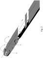
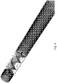
- the vacuum causes the agitator to freely rotate thereby circulating and breaking down fluid drawn in at the other end ( Figs. 2 and 3 ).
- Figs. 4a and 4b show one embodiment of the present invention which is a device that can be affixed to the end of a surgical tube.
- the device has apertures (openings) to allow the passage of viscous and/or non-viscous fluid.
- the device comprises an agitator with a cap configured as an annular ring which has a larger diameter than the stop in the tube or housing. Two caps are present in the depicted embodiment and the caps are similarly configured. In other embodiments, caps on each end of the agitator may be configured differently from one another.
- Figs 5a-5d show views of an agitator including the helical bade, first end, second end, caps, connecting rods, and spokes.
- Figs. 6a and 6b show an end view of one embodiment of the present invention.
- the annular ring is connected to the connecting rod by three spokes.
- the helical blade can also be seen in relation to a longitudinal axis of the cap and shaft.
- Embodiments may or may not be centered along a longitudinal axis of the agitator and/or the tube/housing.
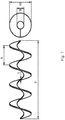
- Fig. 7 shows a diagram illustrating a helical blade according to another embodiment of the present invention.
- T denotes the thickness of the helical blade and x denotes the distance between peaks (periodicity) of the helical blade.
- D denotes the total diameter of the helical blade whereas d denotes the diameter of a central passage of a helical blade of this embodiment.
- the longitudinal length of the helical blade is denoted by y .
- Figs. 8-9 show another embodiment of a device according to an embodiment of the present invention wherein the device is integrated with the surgical tube (either integrally or by removable attachment).
- shafts of the agitator extend longitudinally beyond the extents of the helical blade.
- the shafts may serve as pivot points for rotation of the agitator (e.g., when used with bearings and/or other structures adapted to rotatably engage the shafts.
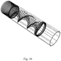
- Figs. 10-11 depict an embodiment of a device having an agitator with another embodiment of an end cap.
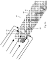
- Figs. 12-14 show another embodiment of a device 80 according to the present disclosure.
- Device 80 has a plurality of apertures 83 located on tube 85.
- the apertures 83 extend through the inner wall 87 of the tube 85.
- the apertures 83 are substantially circular.
- the apertures 83 may be spaced radially around the tube 85.
- the apertures 83 may be located at the distal end of the tube 85.
- the apertures 83 are located at the distal end 91 of the agitator 89.
- the apertures 83 may be located distally or proximally from any point of the agitator 89.
- the apertures 83 are configured for the suction of fluids from the in-situ fluid location.
- Each aperture 83 may be surrounded by a reinforcing ring 81.
- the reinforcing ring 81 may be constructed from the same material as the tube 85 or from a different material.
- the reinforcing ring 81 may have a smooth or rough texture.
- the apertures may be slots.
- the slots may have a long dimension and a short dimension.
- the long dimension of the slot may extend radially around the tube.
- the long dimension of the slot extends distally or proximally along the tube.
- the slot follows a helical path around the tube.
- the apertures may be both slots and circles. Other shapes may be used for the apertures.
- Fig. 15 shows another embodiment of a device 100 according to the present disclosure.
- Device 100 has a plurality of apertures 103 located on the tube 105.
- the apertures 103, 111 extend through the inner wall 107 of the tube 105.
- the first row of apertures 111 is located distally on the tube 105.
- the second row of apertures 103 is located proximally on the tube 105.
- the first row of apertures 111 may be of a different size than the second row of apertures 103.
- the second row of apertures may have a smaller size.
- Figs. 16a -b show another embodiment of a device 120 according to the present disclosure.
- this device 120 there are three rows of radially-spaced apertures.
- the first row 121 is located distally on the tube.
- the second row 123 is located between the first row 121 and the third row 125.
- the third row 125 is located proximally on the tube.
- Fig. 17 shows another embodiment of a device 130 according to the present disclosure.
- this device 130 there are two rows of radially spaced apertures.
- the first row 131 is located distally on the tube.
- the second row 133 is located proximally on the tube.
- Figs 18a -b show another embodiment of device 140 according to the present disclosure.
- this device 140 there are five rows 141, 143, 145, 147, 149 of radially-spaced apertures along the tube. The rows are evenly spaced along the length of the tube.
- One exemplary embodiment is a device for removing viscous or semi-viscous material from an individual using suction provided by a vacuum source.
- the device comprises: a tube having a distal opening, a proximal opening in pneumatic communication with the vacuum source, and a first stop at a first lengthwise position on an inner wall of the tube; and an agitator rotatably disposed in the tube, the agitator having a helical blade, a first end, and a second end, and the first end is configured to engage the first stop such that the agitator is rotatable about the axis of the helical blade while being at a substantially fixed position along the length of the tube.
- the tube has at least one aperture in a wall of the tube located between the proximal and distal openings. In another embodiment, the at least one aperture is located distal to the first stop. In one embodiment, the at least one aperture is located proximal to the first stop. In another embodiment, the at least one aperture is substantially circular. In one embodiment, the at least one aperture is a slot. In another embodiment, the at least one aperture is surrounded by a supporting ring. In another embodiment, the tube has two or more radially-spaced apertures located at the same distance between the proximal and distal opening. In one embodiment, the tube has two or more radially-spaced apertures located in a first row and a second row, the first row having a difference distance between the proximal and the distal openings that the second row.
Landscapes
- Health & Medical Sciences (AREA)
- Life Sciences & Earth Sciences (AREA)
- Surgery (AREA)
- Heart & Thoracic Surgery (AREA)
- Public Health (AREA)
- Animal Behavior & Ethology (AREA)
- Biomedical Technology (AREA)
- Veterinary Medicine (AREA)
- Engineering & Computer Science (AREA)
- General Health & Medical Sciences (AREA)
- Medical Informatics (AREA)
- Molecular Biology (AREA)
- Orthopedic Medicine & Surgery (AREA)
- Nuclear Medicine, Radiotherapy & Molecular Imaging (AREA)
- Vascular Medicine (AREA)
- Anesthesiology (AREA)
- Hematology (AREA)
- Surgical Instruments (AREA)
- External Artificial Organs (AREA)
Claims (15)
- Chirurgische Saugvorrichtung zum Entfernen von zähflüssigem oder halbviskosem Material von einem Individuum unter Verwendung der von einer Vakuumquelle bereitgestellten Saugkraft, wobei die Vorrichtung aufweist:eine Vakuumquelle;ein Rohr (12) mit einer distalen Öffnung (14), einer proximalen Öffnung (16) in pneumatischer Verbindung bei Verwendung mit der Vakuumquelle (90) und einem ersten Anschlag (18) an einer ersten Längsposition an einer Innenwand (13) des Rohres;einen Rührer (20), der drehbar in dem Rohr angeordnet ist, wobei der Rührer eine schraubenförmige Schaufel (26), ein erstes Ende (22) und ein zweites Ende (24) aufweist und das erste Ende so konfiguriert ist, dass es mit dem ersten Anschlag in Eingriff kommt, so dass der Rührer um die Achse der schraubenförmigen Schaufel drehbar ist, während er sich an einer im Wesentlichen festen Position entlang der Länge des Rohres befindet;
dadurch gekennzeichnet, dass der Rührer so konfiguriert ist, dass er sich durch den Fluidstrom durch das Rohr dreht, der durch Anlegen eines Vakuums verursacht wird, wobei die Vakuumquelle so konfiguriert ist, dass sie das Vakuum anlegt, um den Rührer zu drehen, um in das Rohr eingesaugte Feststoffe aufzubrechen. - Vorrichtung nach Anspruch 1, wobei der erste Anschlag ein an der Innenwand des Rohres befestigter Kragen ist.
- Vorrichtung nach Anspruch 1, wobei der erste Anschlag ein Vorsprung ist.
- Vorrichtung nach Anspruch 3, bei der der Vorsprung durch eine Einkerbung in dem Rohr ausgebildet ist.
- Vorrichtung nach Anspruch 1, wobei der erste Anschlag zwei oder mehr Vorsprünge aufweist.
- Vorrichtung nach Anspruch 1, bei der der erste Anschlag so bemessen ist, dass er weniger als 20% des Umfangs der Innenwand bedeckt.
- Vorrichtung nach Anspruch 6, wobei das erste Ende des Rührers als Ring ausgebildet ist.
- Vorrichtung nach Anspruch 7, wobei der Ring über eine Verbindungsstange mit der schraubenförmigen Schaufel verbunden ist.
- Vorrichtung nach Anspruch 1, wobei das Rohr einen zweiten Anschlag (19) an einer zweiten Längsposition an der Innenwand des Rohres aufweist und das zweite Ende des Rührers derart konfiguriert ist, dass es mit dem zweiten Anschlag in Eingriff kommt, so dass sich der Rührer an einer im Wesentlichen festen Position entlang der Länge des Rohres zwischen dem ersten Anschlag und dem zweiten Anschlag befindet.
- Vorrichtung nach Anspruch 9, wobei der zweite Anschlag ein an der Innenwand des Rohres befestigter Kragen ist.
- Vorrichtung nach Anspruch 9, wobei der zweite Anschlag ein Vorsprung ist.
- Vorrichtung nach Anspruch 11, wobei der Vorsprung durch eine Einkerbung in dem Rohr ausgebildet ist.
- Vorrichtung nach Anspruch 9, wobei der zweite Anschlag zwei oder mehr Vorsprünge aufweist.
- Vorrichtung nach Anspruch 9, wobei der zweite Anschlag so bemessen ist, dass er weniger als 20% des Umfangs der Innenwand bedeckt.
- Vorrichtung nach Anspruch 14, wobei das zweite Ende des Rührers als Ring ausgebildet ist.
Applications Claiming Priority (2)
| Application Number | Priority Date | Filing Date | Title |
|---|---|---|---|
| US201361798677P | 2013-03-15 | 2013-03-15 | |
| PCT/US2014/029702 WO2014145052A1 (en) | 2013-03-15 | 2014-03-14 | Suction device for normal and viscous materials |
Publications (3)
| Publication Number | Publication Date |
|---|---|
| EP2967517A1 EP2967517A1 (de) | 2016-01-20 |
| EP2967517A4 EP2967517A4 (de) | 2016-10-19 |
| EP2967517B1 true EP2967517B1 (de) | 2020-12-23 |
Family
ID=51537873
Family Applications (1)
| Application Number | Title | Priority Date | Filing Date |
|---|---|---|---|
| EP14764533.7A Active EP2967517B1 (de) | 2013-03-15 | 2014-03-14 | Saugvorrichtung für normale und viskose stoffe |
Country Status (4)
| Country | Link |
|---|---|
| US (1) | US10286125B2 (de) |
| EP (1) | EP2967517B1 (de) |
| CA (1) | CA2906847C (de) |
| WO (1) | WO2014145052A1 (de) |
Families Citing this family (5)
| Publication number | Priority date | Publication date | Assignee | Title |
|---|---|---|---|---|
| CN104997554B (zh) * | 2015-07-15 | 2018-06-15 | 湖州市妇幼保健院 | 用于子宫切除手术的刀具 |
| US10709472B2 (en) * | 2016-09-13 | 2020-07-14 | Biosense Webster (Israel) Ltd. | Debrider with multiple flushing orifices |
| KR101843145B1 (ko) * | 2017-02-20 | 2018-03-28 | 서울대학교산학협력단 | 의료용 석션 팁 |
| US10918409B2 (en) * | 2017-12-05 | 2021-02-16 | Covidien Lp | Morcellator with auger tissue feeder |
| EP3915605A1 (de) * | 2020-05-27 | 2021-12-01 | Medela Holding AG | Fördervorrichtung für körperflüssigkeit |
Family Cites Families (11)
| Publication number | Priority date | Publication date | Assignee | Title |
|---|---|---|---|---|
| US3485246A (en) | 1966-07-05 | 1969-12-23 | George K Austin Jr | Aspirator device |
| US4649919A (en) * | 1985-01-23 | 1987-03-17 | Precision Surgical Instruments, Inc. | Surgical instrument |
| US5226909A (en) * | 1989-09-12 | 1993-07-13 | Devices For Vascular Intervention, Inc. | Atherectomy device having helical blade and blade guide |
| FR2676365B1 (fr) * | 1991-05-13 | 1993-08-20 | Gerard Adhoute | Dispositif d'aspiration pour autotransfusion per-operatoire. |
| GB9212597D0 (en) | 1992-06-13 | 1992-07-29 | Bennett John P | Medical suction controller jar |
| US5899915A (en) | 1996-12-02 | 1999-05-04 | Angiotrax, Inc. | Apparatus and method for intraoperatively performing surgery |
| US6666874B2 (en) * | 1998-04-10 | 2003-12-23 | Endicor Medical, Inc. | Rotational atherectomy system with serrated cutting tip |
| US6482217B1 (en) | 1998-04-10 | 2002-11-19 | Endicor Medical, Inc. | Neuro thrombectomy catheter |
| US6143009A (en) * | 1999-02-02 | 2000-11-07 | Shiber; Samuel | Flexible-agitator system and method |
| US6626890B2 (en) | 2001-06-06 | 2003-09-30 | Tony R. Brown | Fat removal device and method |
| GR20030100371A (el) * | 2003-09-08 | 2005-05-18 | ������������, ������������� ����������� �.�.� | Καθετηρας ενδοθεραπειας |
-
2014
- 2014-03-14 EP EP14764533.7A patent/EP2967517B1/de active Active
- 2014-03-14 US US14/776,074 patent/US10286125B2/en active Active
- 2014-03-14 WO PCT/US2014/029702 patent/WO2014145052A1/en not_active Ceased
- 2014-03-14 CA CA2906847A patent/CA2906847C/en active Active
Non-Patent Citations (1)
| Title |
|---|
| None * |
Also Published As
| Publication number | Publication date |
|---|---|
| EP2967517A4 (de) | 2016-10-19 |
| CA2906847A1 (en) | 2014-09-18 |
| US20160022883A1 (en) | 2016-01-28 |
| US10286125B2 (en) | 2019-05-14 |
| CA2906847C (en) | 2021-04-27 |
| WO2014145052A1 (en) | 2014-09-18 |
| EP2967517A1 (de) | 2016-01-20 |
Similar Documents
| Publication | Publication Date | Title |
|---|---|---|
| US5947990A (en) | Endoscopic surgical instrument | |
| US5248297A (en) | Suction tube for use in surgical operation | |
| US8906053B2 (en) | Systems and methods for surgical removal of brain tumors | |
| US6540713B1 (en) | Vented aspirator and method | |
| EP0871576B1 (de) | Chirurgisches schneidinstrument mit ansaugung und innerer berieselung | |
| US11612407B2 (en) | Surgical tool arrangement and surgical cutting accessory for use therewith | |
| KR102737246B1 (ko) | 세척 장치 및 상처 세척 및 생물막 제어를 위해 세척 장치에 압축 유체를 전달하기 위한 시스템 | |
| US9737322B2 (en) | Method for resection of tumors and tissues | |
| US20070010823A1 (en) | Arthroscopic shaver system | |
| CN111956876B (zh) | 一种手术防堵吸引管及防堵方法 | |
| CA2906847C (en) | Suction device for normal and viscous materials | |
| JP2017529905A (ja) | 腫瘍マージンデバイス | |
| EP1894585B1 (de) | Einstellbare Aspirationsvorrichtung | |
| US20150196314A1 (en) | Curved Blade Tissue Shaver | |
| CN110496252B (zh) | 一种用于腔镜通道手术的吸引器 | |
| WO2020215125A1 (en) | Dual cannulated suction and delivery device | |
| US12239576B2 (en) | Stent | |
| CN111956875A (zh) | 一种手动式防堵吸引管 | |
| CN111939348B (zh) | 一种快速破碎堵塞物的吸引管 | |
| US20220061874A1 (en) | Suction Tube with Blade | |
| KR200357595Y1 (ko) | 내시경 수술용 혈액흡입기구 | |
| AU2017223498A1 (en) | Yankauer suction system and related methods with clog removal functionality |
Legal Events
| Date | Code | Title | Description |
|---|---|---|---|
| PUAI | Public reference made under article 153(3) epc to a published international application that has entered the european phase |
Free format text: ORIGINAL CODE: 0009012 |
|
| 17P | Request for examination filed |
Effective date: 20150922 |
|
| AK | Designated contracting states |
Kind code of ref document: A1 Designated state(s): AL AT BE BG CH CY CZ DE DK EE ES FI FR GB GR HR HU IE IS IT LI LT LU LV MC MK MT NL NO PL PT RO RS SE SI SK SM TR |
|
| AX | Request for extension of the european patent |
Extension state: BA ME |
|
| DAX | Request for extension of the european patent (deleted) | ||
| A4 | Supplementary search report drawn up and despatched |
Effective date: 20160921 |
|
| RIC1 | Information provided on ipc code assigned before grant |
Ipc: A61B 17/32 20060101ALI20160915BHEP Ipc: A61B 17/00 20060101AFI20160915BHEP |
|
| STAA | Information on the status of an ep patent application or granted ep patent |
Free format text: STATUS: REQUEST FOR EXAMINATION WAS MADE |
|
| STAA | Information on the status of an ep patent application or granted ep patent |
Free format text: STATUS: EXAMINATION IS IN PROGRESS |
|
| 17Q | First examination report despatched |
Effective date: 20180213 |
|
| GRAP | Despatch of communication of intention to grant a patent |
Free format text: ORIGINAL CODE: EPIDOSNIGR1 |
|
| STAA | Information on the status of an ep patent application or granted ep patent |
Free format text: STATUS: GRANT OF PATENT IS INTENDED |
|
| INTG | Intention to grant announced |
Effective date: 20200708 |
|
| GRAS | Grant fee paid |
Free format text: ORIGINAL CODE: EPIDOSNIGR3 |
|
| GRAA | (expected) grant |
Free format text: ORIGINAL CODE: 0009210 |
|
| STAA | Information on the status of an ep patent application or granted ep patent |
Free format text: STATUS: THE PATENT HAS BEEN GRANTED |
|
| AK | Designated contracting states |
Kind code of ref document: B1 Designated state(s): AL AT BE BG CH CY CZ DE DK EE ES FI FR GB GR HR HU IE IS IT LI LT LU LV MC MK MT NL NO PL PT RO RS SE SI SK SM TR |
|
| REG | Reference to a national code |
Ref country code: GB Ref legal event code: FG4D |
|
| REG | Reference to a national code |
Ref country code: DE Ref legal event code: R096 Ref document number: 602014073595 Country of ref document: DE |
|
| REG | Reference to a national code |
Ref country code: AT Ref legal event code: REF Ref document number: 1346919 Country of ref document: AT Kind code of ref document: T Effective date: 20210115 |
|
| REG | Reference to a national code |
Ref country code: IE Ref legal event code: FG4D |
|
| PG25 | Lapsed in a contracting state [announced via postgrant information from national office to epo] |
Ref country code: FI Free format text: LAPSE BECAUSE OF FAILURE TO SUBMIT A TRANSLATION OF THE DESCRIPTION OR TO PAY THE FEE WITHIN THE PRESCRIBED TIME-LIMIT Effective date: 20201223 Ref country code: RS Free format text: LAPSE BECAUSE OF FAILURE TO SUBMIT A TRANSLATION OF THE DESCRIPTION OR TO PAY THE FEE WITHIN THE PRESCRIBED TIME-LIMIT Effective date: 20201223 Ref country code: NO Free format text: LAPSE BECAUSE OF FAILURE TO SUBMIT A TRANSLATION OF THE DESCRIPTION OR TO PAY THE FEE WITHIN THE PRESCRIBED TIME-LIMIT Effective date: 20210323 Ref country code: GR Free format text: LAPSE BECAUSE OF FAILURE TO SUBMIT A TRANSLATION OF THE DESCRIPTION OR TO PAY THE FEE WITHIN THE PRESCRIBED TIME-LIMIT Effective date: 20210324 |
|
| REG | Reference to a national code |
Ref country code: AT Ref legal event code: MK05 Ref document number: 1346919 Country of ref document: AT Kind code of ref document: T Effective date: 20201223 |
|
| REG | Reference to a national code |
Ref country code: NL Ref legal event code: MP Effective date: 20201223 |
|
| PG25 | Lapsed in a contracting state [announced via postgrant information from national office to epo] |
Ref country code: SE Free format text: LAPSE BECAUSE OF FAILURE TO SUBMIT A TRANSLATION OF THE DESCRIPTION OR TO PAY THE FEE WITHIN THE PRESCRIBED TIME-LIMIT Effective date: 20201223 Ref country code: LV Free format text: LAPSE BECAUSE OF FAILURE TO SUBMIT A TRANSLATION OF THE DESCRIPTION OR TO PAY THE FEE WITHIN THE PRESCRIBED TIME-LIMIT Effective date: 20201223 Ref country code: BG Free format text: LAPSE BECAUSE OF FAILURE TO SUBMIT A TRANSLATION OF THE DESCRIPTION OR TO PAY THE FEE WITHIN THE PRESCRIBED TIME-LIMIT Effective date: 20210323 |
|
| PG25 | Lapsed in a contracting state [announced via postgrant information from national office to epo] |
Ref country code: NL Free format text: LAPSE BECAUSE OF FAILURE TO SUBMIT A TRANSLATION OF THE DESCRIPTION OR TO PAY THE FEE WITHIN THE PRESCRIBED TIME-LIMIT Effective date: 20201223 Ref country code: HR Free format text: LAPSE BECAUSE OF FAILURE TO SUBMIT A TRANSLATION OF THE DESCRIPTION OR TO PAY THE FEE WITHIN THE PRESCRIBED TIME-LIMIT Effective date: 20201223 |
|
| REG | Reference to a national code |
Ref country code: LT Ref legal event code: MG9D |
|
| PG25 | Lapsed in a contracting state [announced via postgrant information from national office to epo] |
Ref country code: LT Free format text: LAPSE BECAUSE OF FAILURE TO SUBMIT A TRANSLATION OF THE DESCRIPTION OR TO PAY THE FEE WITHIN THE PRESCRIBED TIME-LIMIT Effective date: 20201223 Ref country code: SK Free format text: LAPSE BECAUSE OF FAILURE TO SUBMIT A TRANSLATION OF THE DESCRIPTION OR TO PAY THE FEE WITHIN THE PRESCRIBED TIME-LIMIT Effective date: 20201223 Ref country code: PT Free format text: LAPSE BECAUSE OF FAILURE TO SUBMIT A TRANSLATION OF THE DESCRIPTION OR TO PAY THE FEE WITHIN THE PRESCRIBED TIME-LIMIT Effective date: 20210423 Ref country code: RO Free format text: LAPSE BECAUSE OF FAILURE TO SUBMIT A TRANSLATION OF THE DESCRIPTION OR TO PAY THE FEE WITHIN THE PRESCRIBED TIME-LIMIT Effective date: 20201223 Ref country code: SM Free format text: LAPSE BECAUSE OF FAILURE TO SUBMIT A TRANSLATION OF THE DESCRIPTION OR TO PAY THE FEE WITHIN THE PRESCRIBED TIME-LIMIT Effective date: 20201223 Ref country code: EE Free format text: LAPSE BECAUSE OF FAILURE TO SUBMIT A TRANSLATION OF THE DESCRIPTION OR TO PAY THE FEE WITHIN THE PRESCRIBED TIME-LIMIT Effective date: 20201223 Ref country code: CZ Free format text: LAPSE BECAUSE OF FAILURE TO SUBMIT A TRANSLATION OF THE DESCRIPTION OR TO PAY THE FEE WITHIN THE PRESCRIBED TIME-LIMIT Effective date: 20201223 |
|
| PG25 | Lapsed in a contracting state [announced via postgrant information from national office to epo] |
Ref country code: PL Free format text: LAPSE BECAUSE OF FAILURE TO SUBMIT A TRANSLATION OF THE DESCRIPTION OR TO PAY THE FEE WITHIN THE PRESCRIBED TIME-LIMIT Effective date: 20201223 Ref country code: AT Free format text: LAPSE BECAUSE OF FAILURE TO SUBMIT A TRANSLATION OF THE DESCRIPTION OR TO PAY THE FEE WITHIN THE PRESCRIBED TIME-LIMIT Effective date: 20201223 |
|
| REG | Reference to a national code |
Ref country code: DE Ref legal event code: R097 Ref document number: 602014073595 Country of ref document: DE |
|
| PG25 | Lapsed in a contracting state [announced via postgrant information from national office to epo] |
Ref country code: IS Free format text: LAPSE BECAUSE OF FAILURE TO SUBMIT A TRANSLATION OF THE DESCRIPTION OR TO PAY THE FEE WITHIN THE PRESCRIBED TIME-LIMIT Effective date: 20210423 |
|
| PG25 | Lapsed in a contracting state [announced via postgrant information from national office to epo] |
Ref country code: MC Free format text: LAPSE BECAUSE OF FAILURE TO SUBMIT A TRANSLATION OF THE DESCRIPTION OR TO PAY THE FEE WITHIN THE PRESCRIBED TIME-LIMIT Effective date: 20201223 Ref country code: AL Free format text: LAPSE BECAUSE OF FAILURE TO SUBMIT A TRANSLATION OF THE DESCRIPTION OR TO PAY THE FEE WITHIN THE PRESCRIBED TIME-LIMIT Effective date: 20201223 Ref country code: IT Free format text: LAPSE BECAUSE OF FAILURE TO SUBMIT A TRANSLATION OF THE DESCRIPTION OR TO PAY THE FEE WITHIN THE PRESCRIBED TIME-LIMIT Effective date: 20201223 |
|
| PLBE | No opposition filed within time limit |
Free format text: ORIGINAL CODE: 0009261 |
|
| REG | Reference to a national code |
Ref country code: CH Ref legal event code: PL |
|
| STAA | Information on the status of an ep patent application or granted ep patent |
Free format text: STATUS: NO OPPOSITION FILED WITHIN TIME LIMIT |
|
| PG25 | Lapsed in a contracting state [announced via postgrant information from national office to epo] |
Ref country code: ES Free format text: LAPSE BECAUSE OF FAILURE TO SUBMIT A TRANSLATION OF THE DESCRIPTION OR TO PAY THE FEE WITHIN THE PRESCRIBED TIME-LIMIT Effective date: 20201223 Ref country code: DK Free format text: LAPSE BECAUSE OF FAILURE TO SUBMIT A TRANSLATION OF THE DESCRIPTION OR TO PAY THE FEE WITHIN THE PRESCRIBED TIME-LIMIT Effective date: 20201223 |
|
| 26N | No opposition filed |
Effective date: 20210924 |
|
| REG | Reference to a national code |
Ref country code: BE Ref legal event code: MM Effective date: 20210331 |
|
| PG25 | Lapsed in a contracting state [announced via postgrant information from national office to epo] |
Ref country code: LI Free format text: LAPSE BECAUSE OF NON-PAYMENT OF DUE FEES Effective date: 20210331 Ref country code: LU Free format text: LAPSE BECAUSE OF NON-PAYMENT OF DUE FEES Effective date: 20210314 Ref country code: CH Free format text: LAPSE BECAUSE OF NON-PAYMENT OF DUE FEES Effective date: 20210331 Ref country code: IE Free format text: LAPSE BECAUSE OF NON-PAYMENT OF DUE FEES Effective date: 20210314 |
|
| PG25 | Lapsed in a contracting state [announced via postgrant information from national office to epo] |
Ref country code: SI Free format text: LAPSE BECAUSE OF FAILURE TO SUBMIT A TRANSLATION OF THE DESCRIPTION OR TO PAY THE FEE WITHIN THE PRESCRIBED TIME-LIMIT Effective date: 20201223 |
|
| PG25 | Lapsed in a contracting state [announced via postgrant information from national office to epo] |
Ref country code: IS Free format text: LAPSE BECAUSE OF FAILURE TO SUBMIT A TRANSLATION OF THE DESCRIPTION OR TO PAY THE FEE WITHIN THE PRESCRIBED TIME-LIMIT Effective date: 20210423 |
|
| PG25 | Lapsed in a contracting state [announced via postgrant information from national office to epo] |
Ref country code: BE Free format text: LAPSE BECAUSE OF NON-PAYMENT OF DUE FEES Effective date: 20210331 |
|
| PG25 | Lapsed in a contracting state [announced via postgrant information from national office to epo] |
Ref country code: HU Free format text: LAPSE BECAUSE OF FAILURE TO SUBMIT A TRANSLATION OF THE DESCRIPTION OR TO PAY THE FEE WITHIN THE PRESCRIBED TIME-LIMIT; INVALID AB INITIO Effective date: 20140314 |
|
| PG25 | Lapsed in a contracting state [announced via postgrant information from national office to epo] |
Ref country code: CY Free format text: LAPSE BECAUSE OF FAILURE TO SUBMIT A TRANSLATION OF THE DESCRIPTION OR TO PAY THE FEE WITHIN THE PRESCRIBED TIME-LIMIT Effective date: 20201223 |
|
| P01 | Opt-out of the competence of the unified patent court (upc) registered |
Effective date: 20230525 |
|
| PG25 | Lapsed in a contracting state [announced via postgrant information from national office to epo] |
Ref country code: MK Free format text: LAPSE BECAUSE OF FAILURE TO SUBMIT A TRANSLATION OF THE DESCRIPTION OR TO PAY THE FEE WITHIN THE PRESCRIBED TIME-LIMIT Effective date: 20201223 |
|
| PG25 | Lapsed in a contracting state [announced via postgrant information from national office to epo] |
Ref country code: TR Free format text: LAPSE BECAUSE OF FAILURE TO SUBMIT A TRANSLATION OF THE DESCRIPTION OR TO PAY THE FEE WITHIN THE PRESCRIBED TIME-LIMIT Effective date: 20201223 |
|
| PG25 | Lapsed in a contracting state [announced via postgrant information from national office to epo] |
Ref country code: MT Free format text: LAPSE BECAUSE OF FAILURE TO SUBMIT A TRANSLATION OF THE DESCRIPTION OR TO PAY THE FEE WITHIN THE PRESCRIBED TIME-LIMIT Effective date: 20201223 |
|
| PGFP | Annual fee paid to national office [announced via postgrant information from national office to epo] |
Ref country code: GB Payment date: 20260220 Year of fee payment: 13 |
|
| PGFP | Annual fee paid to national office [announced via postgrant information from national office to epo] |
Ref country code: DE Payment date: 20260219 Year of fee payment: 13 |
|
| PGFP | Annual fee paid to national office [announced via postgrant information from national office to epo] |
Ref country code: FR Payment date: 20260219 Year of fee payment: 13 |