EP2967257B1 - A device and method for heating tortilla-like food - Google Patents
A device and method for heating tortilla-like food Download PDFInfo
- Publication number
- EP2967257B1 EP2967257B1 EP14769896.3A EP14769896A EP2967257B1 EP 2967257 B1 EP2967257 B1 EP 2967257B1 EP 14769896 A EP14769896 A EP 14769896A EP 2967257 B1 EP2967257 B1 EP 2967257B1
- Authority
- EP
- European Patent Office
- Prior art keywords
- heating
- food
- drum
- tortilla
- assembly
- Prior art date
- Legal status (The legal status is an assumption and is not a legal conclusion. Google has not performed a legal analysis and makes no representation as to the accuracy of the status listed.)
- Active
Links
Images


Classifications
-
- A—HUMAN NECESSITIES
- A47—FURNITURE; DOMESTIC ARTICLES OR APPLIANCES; COFFEE MILLS; SPICE MILLS; SUCTION CLEANERS IN GENERAL
- A47J—KITCHEN EQUIPMENT; COFFEE MILLS; SPICE MILLS; APPARATUS FOR MAKING BEVERAGES
- A47J37/00—Baking; Roasting; Grilling; Frying
- A47J37/06—Roasters; Grills; Sandwich grills
- A47J37/08—Bread-toasters
-
- A—HUMAN NECESSITIES
- A21—BAKING; EDIBLE DOUGHS
- A21D—TREATMENT, e.g. PRESERVATION, OF FLOUR OR DOUGH, e.g. BY ADDITION OF MATERIALS; BAKING; BAKERY PRODUCTS; PRESERVATION THEREOF
- A21D13/00—Finished or partly finished bakery products
- A21D13/40—Products characterised by the type, form or use
- A21D13/42—Tortillas
-
- A—HUMAN NECESSITIES
- A23—FOODS OR FOODSTUFFS; TREATMENT THEREOF, NOT COVERED BY OTHER CLASSES
- A23L—FOODS, FOODSTUFFS, OR NON-ALCOHOLIC BEVERAGES, NOT COVERED BY SUBCLASSES A21D OR A23B-A23J; THEIR PREPARATION OR TREATMENT, e.g. COOKING, MODIFICATION OF NUTRITIVE QUALITIES, PHYSICAL TREATMENT; PRESERVATION OF FOODS OR FOODSTUFFS, IN GENERAL
- A23L5/00—Preparation or treatment of foods or foodstuffs, in general; Food or foodstuffs obtained thereby; Materials therefor
- A23L5/10—General methods of cooking foods, e.g. by roasting or frying
- A23L5/15—General methods of cooking foods, e.g. by roasting or frying using wave energy, irradiation, electrical means or magnetic fields, e.g. oven cooking or roasting using radiant dry heat
-
- A—HUMAN NECESSITIES
- A47—FURNITURE; DOMESTIC ARTICLES OR APPLIANCES; COFFEE MILLS; SPICE MILLS; SUCTION CLEANERS IN GENERAL
- A47J—KITCHEN EQUIPMENT; COFFEE MILLS; SPICE MILLS; APPARATUS FOR MAKING BEVERAGES
- A47J27/00—Cooking-vessels
- A47J27/08—Pressure-cookers; Lids or locking devices specially adapted therefor
-
- A—HUMAN NECESSITIES
- A47—FURNITURE; DOMESTIC ARTICLES OR APPLIANCES; COFFEE MILLS; SPICE MILLS; SUCTION CLEANERS IN GENERAL
- A47J—KITCHEN EQUIPMENT; COFFEE MILLS; SPICE MILLS; APPARATUS FOR MAKING BEVERAGES
- A47J37/00—Baking; Roasting; Grilling; Frying
- A47J37/06—Roasters; Grills; Sandwich grills
- A47J37/08—Bread-toasters
- A47J37/0807—Bread-toasters with radiating heaters and reflectors
-
- A—HUMAN NECESSITIES
- A47—FURNITURE; DOMESTIC ARTICLES OR APPLIANCES; COFFEE MILLS; SPICE MILLS; SUCTION CLEANERS IN GENERAL
- A47J—KITCHEN EQUIPMENT; COFFEE MILLS; SPICE MILLS; APPARATUS FOR MAKING BEVERAGES
- A47J37/00—Baking; Roasting; Grilling; Frying
- A47J37/06—Roasters; Grills; Sandwich grills
- A47J37/08—Bread-toasters
- A47J37/0814—Bread-toasters with automatic bread ejection or timing means
- A47J37/0842—Bread-toasters with automatic bread ejection or timing means with electronic timers
Definitions
- the field relates to a device for heating tortilla-like food and a method for heating thereof.
- the tortilla is a basic food in Hispanic homes in the United States and around the world. Typically made of corn or flour, the tortilla is served warm at every meal. Typically in the United States a tortilla is flat, round and six-inches in diameter. Conventionally, a tortilla is heated in a skillet on each side. Heating in a skillet, the surface of the tortilla in contact with the skillet is toasted and it acquires a bit of a skin. The tortilla is typically then flipped and the other side of the flat tortilla is warmed and it too acquires a bit of a skin. Typically, a family eats six to twelve tortillas at a meal.
- the skillet warming method requires a minimum of one minute per side. Only four tortillas can be warmed in a typical skillet. Some persons tasked with warming tortillas have tried to use the microwave oven to warm the tortilla but microwave cooking does not result in the desired consistency as the tortillas become too moist. Moreover, in the microwave a tortilla is warmed from the inside out. In the skillet, a tortilla is toasted from the outside with heat permeating the interior. Inventor found a number of patents on devices to warm tortillas.
- DE 3628617 discloses a controlled rotating toaster for toasting bread.
- the long dimension of the bread is perpendicular to the plane of rotation.
- the figure 1 shows how a slice of bread placed in slot would only have heat from the side of the slot closer to the floor unless the bread were wide enough to fill the entire slot putting the sides of the bread in communication with both the top and bottom of the slot.
- the control mechanism is limited to control of the rotation of the drum.
- US 2009/0064870 identifies as the problem of toasters where with thinner bread the bread leans toward one part of the steel mesh resulting non-uniformity of toasting.
- the problem is solve by providing a set of steel mesh that pivot so as to hold bread when the user pushes down the bread elevating mechanism .
- the Steel Meshes close on the bread so as to hold it during toasting between mica cooking surfaces.
- US 4 745 855 disclosed improved efficiency in toasting bread by replacing the traditional bread guide with an insulating sheet and a narrower bread guide positioned in juxtaposition with the insulating sheet.
- the object of US 4 745 855 shows as "the spacing of the gratings and the heating wires is considerably reduced from which results lower wattage required in the heater wires without any loss of safety.
- This solution also teaches self-centering guide assemblies that intended to keep the bread away from the heating assemblies.
- GB 1488907 disclosed a countertop hollow rigid body oven that when in a vertical orientation can be fitted with either a removable grid or skewers/rods for toasting bread or cooking meats suspended in the cooking chamber or in a horizontal orientation the cooking chamber cooking items on a removable tray.
- Crostino toaster which is disclosed on website http://www.gadgetsandgizmos.org/crostino-twists-your-toast-avoids-burnt-fingers .
- said toaster comprising upright support base with a pair of end caps and a drum like body secured on the base.
- the drum is ratable mounted about a horizontal axis.
- the toaster has two slots on its horizontal surface which provide access to a heating means located within the drum.
- the drum rotating from a receiving position with a slots facing upward to a discharge position with the slots facing downward .
- the Crostino teaser is especially configured to heat bread, bagels and act.
- the invention is an improved tortilla toaster able to be stationed on a tabletop and able to heat six standard six-inch tortillas in about 90-seconds and, with a barrel or drum pivot of the heating area, deliver the warm, toasted tortillas onto a plate or tray without risking a burn to the hands of the user.
- the improved tortilla toaster also reduces risks of shock or electrocution because, unlike a bread toaster with exposed electric wires where a person wielding a utensil might stick said utensil in a toaster and make contact with the electric wires, the improved tortilla toaster has no exposed electric wires.
- heat is provided by Nichrome wires wrapped around a mica board and that mica board is sandwiched between two other mica boards devoid of electric wires.
- the improved tortilla toaster is able to accept up to six six-inch corn or flour tortillas.
- the improved tortilla toaster has a base with a left end cap and a right end cap.
- the left pivot pin rests in a socket in the interior of the leg of the left end cap.
- the right pivot pin rests in a socket in the interior of the leg of the right end cap.
- Inside the outer oven is a drum-shaped or half -barrel-shaped inner oven wall. Mounted in the inner oven wall are seven heating modules. On the extreme left and right sides is a thermal brake to prevent heat melting either end cap.
- the end caps could be made of metal or plastic.
- the end caps would likely be formed of molded plastic.
- Each heating module is comprised of a mica heating plate wrapped with Nichrome wire with a mica thermal diffuser on either side of said heating plate with a steel cage guard on either side of said mica thermal diffuser and an assembly retainer that holds the above identified pieces together. All internal parts of the improved tortilla toaster are food grade products.
- the cage guards are food grade steel or stainless steel.
- AC power is from the wall (or any AC source of similar character to typical home AC power) and the cord enters the device in the base of the device. The cord connects in the right end cap to the DPST ("double pole single throw") Contact installed on the right side outer enclosure plate.
- the DPST Contact on the right side outer enclosure plate makes contact with the DPST Contact mounted on thermal brake.
- AC Power is then distributed from the DPST Contact on the thermal brake to wires that carry power to the control board and the heating modules.
- a user may adjust a knob connected to a variable resister or potentiometer on the control board through the outer oven enclosure to adjust the time of the heating and toasting of the tortilla toaster cycle.
- the forward and rearward edge of the half-barrel or drum is fitted with a combination manual rotation lever and switch.
- the improved tortilla toaster would typically be set on a counter or table or shelf or dashboard or seat approximately parallel to the ground. When the improved tortilla toaster is in use, then the forward and rearward combination manual rotation lever and switch are approximately parallel to the table top. When the improved tortilla toaster is not in service, then the forward combination manual rotation lever and switch is lower than the rearward combination manual rotation lever and switch.
- the oven assembly is weighted so that the forward combination manual rotation lever rests about 30° forward. The forward combination manual rotation lever and switch and oven assembly can further barrel-pivot or drum-pivot forward to release the hot tortillas.
- the steps for using the improved tortilla toaster are as follows:
- the objects of this improved tortilla toaster invention include but are not limited to:
- the improved tortilla toaster provides for heating up to six tortillas at one time. Rather than heat the tortilla on one side at a time as a user would in a skillet, the improved tortilla toaster provides for toasting and heating of two sides at one time. Unlike a bread toaster that uses an exposed wire heater to toast, the improved tortilla toaster uses mica thermal diffusers to even out heat and spread the heat to optimize toasting and heating a tortilla. Moreover, the improved tortilla toaster is engineered to operate off of a standard 15 Amperes line available in most homes in the United States.
- the improved tortilla toaster operates off of both temperature and time to achieve optimal doneness.
- the heart of the control circuit is an 8-bit microcontroller PIC 18F13K22 (in Fig. 8 called 'NUNI CONTROLLER') which is configured as follows:
- the controller is predicated on both the toasting temperature, and, once the temperature is reached, the user can select time (what a user might term "done-ness") by adjusting the adjustment knob. Neither time nor temperature alone are suitable to achieve consistent tortilla toasting.
- the block diagram is included as Fig. 8 .
- the heating modules are connected to the AC as well as the microcontroller which turns on the electromagnet that holds the outer oven enclosure in place in the parallel to the surface position described earlier.
- the microcontroller signals to the user that the tortilla toaster is heating by blinking an LED just adjacent the knob.
- the user may exercise a personal preference loading the tortillas in the tortilla toaster before starting the heating cycle or after the tortilla toaster has come to temperature without a loss in efficiency or effectiveness.
- the control circuit's temperature measurement element (a Negative Temperature Coefficient Thermistor) is mounted in the inner oven to measure the oven temperature.
- the resistance changes in response to the temperature in the toaster with its resistance dropping to a well characterized resistance vs. temperature curve as the temperature rises.
- the microcontroller selected for the tortilla toaster includes A to D (Analog to Digital) converter that's built into the microcontroller.
- the A to D converter allows the microcontroller to convert a small voltage (analog) produced by the Thermistor into a binary number (digital).
- the voltage the Thermistor produces is proportional to the temperature inside the tortilla toaster.
- the number that the A to D converter obtains by measuring the voltage produced by the Thermistor is a numeric representation of the tortilla toaster's internal temperature. This number is used by the microcontroller's logic to determine the readiness of the tortilla toaster to start the toasting cycle.
- the microcontroller samples the tortilla toaster's internal temperature nearly continuously.
- the tortilla toaster indicates that it is coming to toasting temperature but not yet there by blinking an LED adjacent to the adjustment knob.
- the microcontroller will skip the coming to toasting temperature phase. Since the microcontroller continuously monitors the internal temperature of the Inner Oven Enclosure, the microcontroller will know if it can transition into the toasting cycle without a heating delay.
- the logic tells the program that the Inner Oven Enclosure is officially "HOT” and the toasting timing or duration, set by the knob mounted on the front of the Outer Oven Enclosure, begins and this is signaled by the LED illuminating continuously instead of blinking.
- the toasting duration is selected via the rotary code switch which has 16 separate positions. A switch with fewer positions could be used. The position of the switch is communicated to the microcontroller via 4 lines.
- the toasting duration (timing) is adjustable from a range that goes from 15-seconds to 90-seconds, per the below table. The darker cells show the variability if a 10-position switch were used.
- inventor due to a surplus of drive pins on the microcontroller, might include a beeper alarm for the end of the toasting cycle but the alarm can be left out without undermining operation of the microcontroller.
- the components include a thermistor for measuring temperature in the Inner Oven Enclosure, a rotary code switch for selecting toasting duration, a transistor-like semi-conductor for energizing the electromagnet, an LED to indicate state of the device, and, optimally, a beeper, and an AC power supply.
- This control board connects to the AC line via the DPST Switch contacts that are part of the rotating mechanism, so the controller board itself does not carry the heavy load of the heaters.
- the heaters are connected in parallel to the DPST Switch contacts.
- There is one DPST Contact Assembly that sits in the Right-Hand end cap which connects to the line-cord and there is a second, opposing DPST Contact Assembly that is carried on the rotating oven assembly that connects to the heaters and to the control board.
- the improved tortilla toaster 100 is comprised of a left end cap unit 120 and a right end cap unit 140 which are formed with a flat bottom edge for resting on a flat surface such as a tabletop.
- the left end cap is comprised of three pieces: left outer end cap 123, left inner end cap 124 and a left outer oven enclosure plate 125.
- Left outer end cap 123 and left inner end cap 124 are joined with molded clips or other attachment means.
- the left outer oven enclosure plate 125 fits in a recess in left inner end cap 124.
- the left outer enclosure plate 125 has a plurality of tabs 126.
- the left outer enclosure plate 125 has a hole in the approximate center of said plate.
- the oven is comprised of left and right thermal brakes 170a, 170b which to which are secured with securing means a left pivot rod 350 and a right pivot rod 355 and an oven assembly 600.
- left inside end cap 120 has a left socket 530.
- the left pivot rod 350 is seated through said left outer enclosure plate 125 and into left socket 530.
- the right outer enclosure plate 127 fits in a recess in right inner end cap 135.
- the right outer enclosure plate 127 has a plurality of tabs 128.
- the right outer enclosure plate 127 has a hole in the approximate center of said plate.
- right end cap unit 140 has a right socket 535.
- the right pivot rod 355 is seated through said hole in said right outer enclosure plate 127 and into right socket 535.
- the outer enclosure plates 125 and 127 have holes large enough to allow the left and right pivot rods 350, 355 to protrude through the plates without binding on them.
- the oven 600 is comprised of two barrel-like or drum-like structures, an outer oven enclosure 160 and an inner oven enclosure 360.
- the inner oven enclosure 360 nests within the outer oven enclosure 160.
- the outer oven enclosure 160 on the left side is secured to bracket 550 with rivets or other securing means.
- the left side of outer oven enclosure 160 with bracket 550 is secured to left outer oven enclosure plate 125 using a plurality of tabs 126.
- the outer oven enclosure 160 on the right side is secured to bracket 555 with rivets or other securing means.
- the right side of the outer oven enclosure 160 with bracket 555 is secured to the right outer oven enclosure plate 127 using a plurality of tabs 128.
- Fig. 7a shows the seven heating modules in the preferred embodiment of the invention. As you will read below, there are one-sided and two-sided heating modules. Of the seven heating modules, the first and seventh heating modules are one-sided heating modules since outer heating modules only have potential contact with a tortilla on one side. Heating modules in the middle five positions have potential contact with a tortilla on both sides of the modules.
- a two-sided heating module 245, as shown in Fig. 5 is comprised of a left side cage guard 180, a first mica thermal diffuser 310, a mica board 330 wrapped with Nichrome ribbons 320, a second mica thermal diffuser 310, a right side cage guard 180 and the entire heating module 245 is held together with assembly retainer 250.
- a one-sided heating module 240 is the same as a two-sided heating module 245 except that the Nichrome ribbons are only present on one side of the mica board 330.
- the paddle-shaped mica board 330 is notched with a plurality of notches 342.
- mica board 330 has connection tab 300.
- Connection tab 300 has wire lay notches 270.
- Nichrome lead wire 290 feeds the Nichrome ribbons 320 that are wound around mica board 330 ending in wire lay notch 270 and wire loop Nichrome terminal 280.
- mica thermal diffuser 310 On either side of mica board 330 is mica thermal diffuser 310.
- the heating module of cage guard 180, mica thermal diffuser 310, mica board 330, mica thermal diffuser 310, cage guard 180 are held together with assembly retainer 250.
- the improved tortilla toaster makes use of five two-sided heating modules 245 and two one-sided heating modules 240.
- the inner oven enclosure 360 is fabricated with seven regularly spaced bottom slots 565 and seven regularly spaced forward and rearward side slots 575.
- the left side thermal brake 170a is secured with rivets or other securing means and bracket 550 to the left edge of the inner oven enclosure 360.
- a one-sided heating module 240 (active side facing to right side) is installed in the extreme left slot 565 such that connection tab 300 protrudes through the bottom of inner oven enclosure 360.
- Five two-sided heating modules 245 are installed in the center five bottom slots such that connection tab 300 protrudes through the bottom of inner oven enclosure 360.
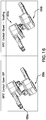
- Figs. 17 a one-sided heating module 240 (active side facing to right side) is installed in the extreme left slot 565 such that connection tab 300 protrudes through the bottom of inner oven enclosure 360.
- Five two-sided heating modules 245 are installed in the center five bottom slots such that connection tab 300 protrudes through the bottom of inner oven enclosure 360.
- a one-sided heating module 240 (active side facing to left side) is installed in the extreme right slot 565 such that connection tab 300 protrudes through the bottom of inner oven enclosure 360.
- the right side thermal brake 170b is secured to with rivets or other securing means and bracket 555 to the right edge of the inner oven enclosure 360.
- an AC power cord comes from an electric source into the right end cap 137 and connects to the DPST Contact 650b mounted Right Plate 127.
- the DPST Contact 650a is mounted on the right thermal brake 170b. Wire leads run from the DPST Contact 650a to the one sided heating module 240 adjacent the right thermal brake 170b and connects at the wire lay notch 270.
- Another set of wire leads run from the wire lay notch 270 to the control board 380.
- the heating modules are powered with wires that run pier to pier from one heating module to the next connected at the wire lay notches 270 on each heating module 240, 245.
- Another set of wire leads run from the control board 380 to electromagnet 660 mounted on the thermal brake 170b.
- the inner oven assembly 585 is secured in the outer oven enclosure 160 using the left bracket 550 and right bracket 555.
- the retention tab 230 as shown in Figure 4 on each assembly retainer 250 on each heating module 240, 245 is locked into place by the forward combination manual rotation lever and switch 110 which is secured to the brackets 550, 555 and front edge of outer oven enclosure 160 with securing means and the rearward combination manual rotation lever and switch 220 which is also secured to the brackets 550, 555 and the rear edge of the outer oven enclosure 160.
- Six finger guards 130 are secured in the forward combination manual rotation lever and switch 110 and rearward combination manual rotation lever and switch 220.
- the outer oven assembly 595 is mounted in the left end cap unit 120 and right end cap unit 140 by the left pivot rod 350 on the left thermal brake 170a nesting through the left outer oven enclosure plate 125 into the left socket 530 and the right pivot rod 355 on the right thermal brake 170b nesting through the right outer oven enclosure plate 127 into the right socket 535.
- Left and right torsion springs 540, 545 are installed on left and right pivot rods 530, 535 to control the rolling of the oven assembly 600.
- the improved tortilla toaster as shown in Fig. 13 , is specifically configured.
- the thickness, T h of the two mica thermal diffusers 310 along with the mica heating plate 330 is about 0.0785 inches.
- O w the optimal distance from the outside of each mica thermal diffuser 310 to the cage guard 180
- W slot the loading zone 190 between two opposing cage guards 180, W slot
- Pitch heating center of one mica heating plate 330 to the adjacent center of mica heating plate
- Pitch heating center of one mica heating plate 330 to the adjacent center of mica heating plate
- the diameter of the hot zone, D HZ was established by experimentation to be about 5.5 inches.
- the diameter of the mica heater assembly, D HTR was established by experimentation to be about 6.0 inches.
- the diameter of the cage guard 180 (here called by the alternate name "wire cloth”) was determined by experiment to be about 6.5 inches.
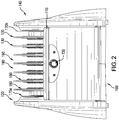
- Figs. 1 , 2 , 3 , 7b , 8 , 9a , 9b 14 , 15 , 17 , and 18 show the adjustment knob 150 mounted on the front of the outer oven enclosure 160.
- the knob 150 connects through the outer oven enclosure and attaches to the control board 380.
- the control board 380 is mounted on the inside of the outer oven enclosure 160 although the knob 150 includes a LED indicator light above it.
- the adjustment knob 150 connects to the Duration Rotary Switch on the control board 380.
- the Duration Rotary Switch has either 10 or 16 positions.
- the control board 380 is connected to a thermistor 625 that protrudes into or has access through an aperture to the inner oven 360 to measure the temperature in the inner oven 360.
- the improved tortilla toaster is turned on by rotating the forward combination manual rotation lever and switch 110 or the rearward combination manual rotation lever and switch 220 so that they are about parallel to the table top on the improved tortilla toaster is resting. That rotation brings into contact DPST contacts 650a and 650b (connecting the improved tortilla toaster to AC line power) and moves the bent tab 400 to a position in contact with electromagnet 660. Connected to AC line power, the microcontroller marked PIC18F13K22 on wire diagram Figure 9a , starts the heating process of the heating modules 240, 245.
- the electromagnet 660 when energized and bent tab 400 keep the improved tortilla toaster in the operating position with the front combination manual rotation lever and switch 110 and rear combination manual rotation lever and switch 220 approximately parallel to the ground or surface on which the improved tortilla toaster.
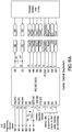
- Figure 9a is the toaster control electronics for the improved tortilla toaster.
- Figure 9b is the circuitry diagram for the improved tortilla toaster.
- the power lead 370 connects to the control board 380.
- Fig. 11 shows the steps of using the improved tortilla toaster.
- Fig. 11a shows the improved tortilla toaster in its resting position where the forward combination manual rotation lever and switch 110 is rotated a bit and down such that the rearward combination manual rotation lever and switch 220 is a bit up. At this point, the user would load tortillas in the improved tortilla toaster.
- Fig. 11b shows that by rotating the forward combination manual rotation lever and switch 110 or the rearward combination manual rotation lever or switch 220 so that they are parallel to the table top, the improved tortilla toaster engages and heats.
- Fig. 11a shows the improved tortilla toaster in its resting position where the forward combination manual rotation lever and switch 110 is rotated a bit and down such that the rearward combination manual rotation lever and switch 220 is a bit up. At this point, the user would load tortillas in the improved tortilla toaster.
- Fig. 11b shows that by rotating the forward combination manual rotation lever and switch 110 or the rearward combination manual rotation lever or switch 220 so that they are
- FIG. 11c shows how at the end of the time cycle (when the electromagnet 660 releases the bent tab 400 and the oven assembly pivots forward and right and left pivot rods 350, 355 cause the oven assembly 600 to rotate to its rest position) releases the forward combination manual rotation lever and switch 110 and rearward combination manual rotation lever and switch 220 would once again return to a rest position.
- the user may rotate the oven assembly by pressing down the forward combination manual rotation lever and switch 110 or by pulling over the rearward combination manual rotation lever and switch 220 for the heated tortillas to slide from the improved tortilla toaster. After removing the tortillas and with or without assistance from the user the oven assembly 600 would rotate back to its rest position (as shown in figure 11a ) as it is weighted to have a resting position of approximately 30° forward.
Description
- The field relates to a device for heating tortilla-like food and a method for heating thereof.
- The tortilla is a basic food in Hispanic homes in the United States and around the world. Typically made of corn or flour, the tortilla is served warm at every meal. Typically in the United States a tortilla is flat, round and six-inches in diameter. Conventionally, a tortilla is heated in a skillet on each side. Heating in a skillet, the surface of the tortilla in contact with the skillet is toasted and it acquires a bit of a skin. The tortilla is typically then flipped and the other side of the flat tortilla is warmed and it too acquires a bit of a skin. Typically, a family eats six to twelve tortillas at a meal.
- Warming enough tortillas for a meal presents a problem. The skillet warming method requires a minimum of one minute per side. Only four tortillas can be warmed in a typical skillet. Some persons tasked with warming tortillas have tried to use the microwave oven to warm the tortilla but microwave cooking does not result in the desired consistency as the tortillas become too moist. Moreover, in the microwave a tortilla is warmed from the inside out. In the skillet, a tortilla is toasted from the outside with heat permeating the interior. Inventor found a number of patents on devices to warm tortillas.
-
DE 3628617 discloses a controlled rotating toaster for toasting bread. The long dimension of the bread is perpendicular to the plane of rotation. Thefigure 1 shows how a slice of bread placed in slot would only have heat from the side of the slot closer to the floor unless the bread were wide enough to fill the entire slot putting the sides of the bread in communication with both the top and bottom of the slot. The control mechanism is limited to control of the rotation of the drum. -
US 2009/0064870 identifies as the problem of toasters where with thinner bread the bread leans toward one part of the steel mesh resulting non-uniformity of toasting. - The problem is solve by providing a set of steel mesh that pivot so as to hold bread when the user pushes down the bread elevating mechanism . The Steel Meshes close on the bread so as to hold it during toasting between mica cooking surfaces.
-
US 4 745 855 disclosed improved efficiency in toasting bread by replacing the traditional bread guide with an insulating sheet and a narrower bread guide positioned in juxtaposition with the insulating sheet. The object ofUS 4 745 855 shows as "the spacing of the gratings and the heating wires is considerably reduced from which results lower wattage required in the heater wires without any loss of safety. This solution also teaches self-centering guide assemblies that intended to keep the bread away from the heating assemblies. -
GB 1488907 - It is known from the Sharp' s publication the Crostino toaster which is disclosed on website http://www.gadgetsandgizmos.org/crostino-twists-your-toast-avoids-burnt-fingers . As it is presented in the pictures said toaster comprising upright support base with a pair of end caps and a drum like body secured on the base. The drum is ratable mounted about a horizontal axis. The toaster has two slots on its horizontal surface which provide access to a heating means located within the drum. The drum rotating from a receiving position with a slots facing upward to a discharge position with the slots facing downward . The Crostino teaser is especially configured to heat bread, bagels and act.
- The invention is an improved tortilla toaster able to be stationed on a tabletop and able to heat six standard six-inch tortillas in about 90-seconds and, with a barrel or drum pivot of the heating area, deliver the warm, toasted tortillas onto a plate or tray without risking a burn to the hands of the user. The improved tortilla toaster also reduces risks of shock or electrocution because, unlike a bread toaster with exposed electric wires where a person wielding a utensil might stick said utensil in a toaster and make contact with the electric wires, the improved tortilla toaster has no exposed electric wires. As discussed below, heat is provided by Nichrome wires wrapped around a mica board and that mica board is sandwiched between two other mica boards devoid of electric wires.
- As shown in the accompanying drawings, the improved tortilla toaster is able to accept up to six six-inch corn or flour tortillas. The improved tortilla toaster has a base with a left end cap and a right end cap. There is drum-shaped or half-barrel-shaped outer oven wall with a left pivot pin and a right pivot pin. The left pivot pin rests in a socket in the interior of the leg of the left end cap. The right pivot pin rests in a socket in the interior of the leg of the right end cap. Inside the outer oven is a drum-shaped or half -barrel-shaped inner oven wall. Mounted in the inner oven wall are seven heating modules. On the extreme left and right sides is a thermal brake to prevent heat melting either end cap. In the preferred embodiment, the end caps could be made of metal or plastic. For reasons of cost, the end caps would likely be formed of molded plastic. Each heating module is comprised of a mica heating plate wrapped with Nichrome wire with a mica thermal diffuser on either side of said heating plate with a steel cage guard on either side of said mica thermal diffuser and an assembly retainer that holds the above identified pieces together. All internal parts of the improved tortilla toaster are food grade products. The cage guards are food grade steel or stainless steel. AC power is from the wall (or any AC source of similar character to typical home AC power) and the cord enters the device in the base of the device. The cord connects in the right end cap to the DPST ("double pole single throw") Contact installed on the right side outer enclosure plate. When the tortilla toaster is set so that the front and back sills are approximately parallel to the ground, then the DPST Contact on the right side outer enclosure plate makes contact with the DPST Contact mounted on thermal brake. AC Power is then distributed from the DPST Contact on the thermal brake to wires that carry power to the control board and the heating modules.
- A user may adjust a knob connected to a variable resister or potentiometer on the control board through the outer oven enclosure to adjust the time of the heating and toasting of the tortilla toaster cycle. The forward and rearward edge of the half-barrel or drum is fitted with a combination manual rotation lever and switch.
- The improved tortilla toaster would typically be set on a counter or table or shelf or dashboard or seat approximately parallel to the ground. When the improved tortilla toaster is in use, then the forward and rearward combination manual rotation lever and switch are approximately parallel to the table top. When the improved tortilla toaster is not in service, then the forward combination manual rotation lever and switch is lower than the rearward combination manual rotation lever and switch. In the preferred embodiment, the oven assembly is weighted so that the forward combination manual rotation lever rests about 30° forward. The forward combination manual rotation lever and switch and oven assembly can further barrel-pivot or drum-pivot forward to release the hot tortillas.
- The steps for using the improved tortilla toaster are as follows:
- 1. At its resting position, the forward combination manual rotation lever and switch will rest about 30° lower than the rearward combination manual rotation lever and switch;
- 2. The user will load the desired number of slots in the improved tortilla toaster with one or more tortillas (a user could elect to load tortillas after the unit has reached operating temperature without compromising effectiveness of the toasting operation);
- 3. The user will barrel-roll the forward combination manual rotation lever and switch and rearward combination manual rotation lever and switch until they are approximately parallel to one another thereby turning on the improved tortilla toaster;
- 4. The improved tortilla toaster will heat the tortillas in the heater for the time set on the adjustment knob;
- 5. At the end of the cycle, the oven enclosure assembly will rotate forward to to rest position;
- 6. The user may further rotate the oven enclosure assembly until the hot tortillas slide from the improved tortilla toaster;
- 7. When the user releases the forward and rearward combination manual rotation lever and switch, then the barrel will pivot back to the near parallel position where the oven enclosure assembly rests;
- 8. Repeat with one or more additional tortillas.
- The objects of this improved tortilla toaster invention include but are not limited to:
- To provide for tabletop or reasonable equivalent heating of multiple tortillas simultaneously;
- To provide for rapid risk-free emptying of the improved tortilla toaster that takes advantage of the tortilla shape and gravity;
- To provide for simultaneous heating on both sides of the a tortilla;
- To provide even heating of tortillas; and,
- To provide heating of tortillas without the risk of electrocution.
- The preferred embodiment of the improved tortilla toaster is shown in the accompanying figures. Essentially, the improved tortilla toaster provides for heating up to six tortillas at one time. Rather than heat the tortilla on one side at a time as a user would in a skillet, the improved tortilla toaster provides for toasting and heating of two sides at one time. Unlike a bread toaster that uses an exposed wire heater to toast, the improved tortilla toaster uses mica thermal diffusers to even out heat and spread the heat to optimize toasting and heating a tortilla. Moreover, the improved tortilla toaster is engineered to operate off of a standard 15 Amperes line available in most homes in the United States.
- The improved tortilla toaster operates off of both temperature and time to achieve optimal doneness. The heart of the control circuit is an 8-bit microcontroller PIC 18F13K22 (in
Fig. 8 called 'NUNI CONTROLLER') which is configured as follows: - 1. Insert tortillas in the improved tortilla toaster
- 2. Rock the housing backward to activate the heating cycle
- 3. When toasting is complete, the heating process stops and the toaster housing is released forward slightly to its original position
- 4. Rotate the toaster housing to present the tortillas for retrieval.
- The controller is predicated on both the toasting temperature, and, once the temperature is reached, the user can select time (what a user might term "done-ness") by adjusting the adjustment knob. Neither time nor temperature alone are suitable to achieve consistent tortilla toasting. The block diagram is included as
Fig. 8 . - When the user closes the switch contacts (by rotating the outer oven enclosure so that the cage guards are up), the heating modules are connected to the AC as well as the microcontroller which turns on the electromagnet that holds the outer oven enclosure in place in the parallel to the surface position described earlier. The microcontroller signals to the user that the tortilla toaster is heating by blinking an LED just adjacent the knob.
- The user may exercise a personal preference loading the tortillas in the tortilla toaster before starting the heating cycle or after the tortilla toaster has come to temperature without a loss in efficiency or effectiveness.
- The control circuit's temperature measurement element (a Negative Temperature Coefficient Thermistor) is mounted in the inner oven to measure the oven temperature. In the Thermistor, the resistance changes in response to the temperature in the toaster with its resistance dropping to a well characterized resistance vs. temperature curve as the temperature rises.
- The microcontroller selected for the tortilla toaster includes A to D (Analog to Digital) converter that's built into the microcontroller. The A to D converter allows the microcontroller to convert a small voltage (analog) produced by the Thermistor into a binary number (digital). The voltage the Thermistor produces is proportional to the temperature inside the tortilla toaster. Hence, the number that the A to D converter obtains by measuring the voltage produced by the Thermistor is a numeric representation of the tortilla toaster's internal temperature. This number is used by the microcontroller's logic to determine the readiness of the tortilla toaster to start the toasting cycle. The microcontroller samples the tortilla toaster's internal temperature nearly continuously. During this heating phase, the tortilla toaster indicates that it is coming to toasting temperature but not yet there by blinking an LED adjacent to the adjustment knob. However, if the Inner Oven Enclosure is already at toasting temperature, the microcontroller will skip the coming to toasting temperature phase. Since the microcontroller continuously monitors the internal temperature of the Inner Oven Enclosure, the microcontroller will know if it can transition into the toasting cycle without a heating delay.
- Once the microcontroller determines that the critical toasting temperature is reached (through experimentation inventor determined a starting or "factory-set" value of about 50°C (about 122°F)) the logic tells the program that the Inner Oven Enclosure is officially "HOT" and the toasting timing or duration, set by the knob mounted on the front of the Outer Oven Enclosure, begins and this is signaled by the LED illuminating continuously instead of blinking.
- The toasting duration is selected via the rotary code switch which has 16 separate positions. A switch with fewer positions could be used. The position of the switch is communicated to the microcontroller via 4 lines. The toasting duration (timing) is adjustable from a range that goes from 15-seconds to 90-seconds, per the below table.

- Once the timer is decremented to zero, the logic turns of the electromagnet that hold the DPST Switch Contacts closed and the heating modules are therefore extinguished. As a result of the loss of holding force, the Inner Oven Enclosure and Outer Oven Enclosures should rotate to its resting position (about 30° forward) simply due to where the concentration of mass is located on the Inner Oven Enclosure and Outer Oven Enclosure. The "Time and Temperature" based approach will produce consistent batch-to-batch tortilla toasting outcomes.
- Optionally, inventor, due to a surplus of drive pins on the microcontroller, might include a beeper alarm for the end of the toasting cycle but the alarm can be left out without undermining operation of the microcontroller.
- Aside from the microcontroller, the components include a thermistor for measuring temperature in the Inner Oven Enclosure, a rotary code switch for selecting toasting duration, a transistor-like semi-conductor for energizing the electromagnet, an LED to indicate state of the device, and, optimally, a beeper, and an AC power supply.
- This control board connects to the AC line via the DPST Switch contacts that are part of the rotating mechanism, so the controller board itself does not carry the heavy load of the heaters. The heaters are connected in parallel to the DPST Switch contacts. There is one DPST Contact Assembly that sits in the Right-Hand end cap which connects to the line-cord and there is a second, opposing DPST Contact Assembly that is carried on the rotating oven assembly that connects to the heaters and to the control board. When the DPST contacts are open (not in contact) then the tortilla toaster is not toasting. When the DPST contacts are closed, then the tortilla toaster is toasting. The only connection that the controller board makes (aside from connecting to the AC line) is to the electromagnet which holds the DPST Switch contacts closed during the toasting cycle. So the DPST Switch Contacts carry the complete load of the heaters and completely disconnects the toaster from the AC power when toasting is complete without even the controller connected to the AC line so that the tortilla toaster draws no electricity when it is not on.
- The following sections more precisely disclose assembly and operation of the improved tortilla toaster.
-
-
Fig. 1 a perspective view of the improved tortilla toaster. -
Fig. 2 is a front elevation of the improved tortilla toaster. -
Fig. 3 is top plan view of the improved tortilla toaster. -
Fig. 4 is a perspective of the heating module assembled for the improved tortilla toaster. -
Fig. 5 is an exploded isometric view of the heating module for the improved tortilla toaster. -
Fig. 6 is a right side view of the improved tortilla toaster. -
Fig. 7a is a cut away view taken along the 7a-7a line ofFig. 3 of the improved tortilla toaster. -
Fig. 7b is a cut away view taken along the 7b-7b line ofFig. 3 of the improved tortilla toaster. -
Fig. 8 is a block diagram that depicts how the moveable section is manually brought into contact with the stationary section by user showing contacts are closed and an electromagnet activates and controller first sets threshold temperature against factory-set value and then tests toasting time against user-set values by the knob. When both the threshold temperature equals the factory set value and the toaster time equals the user-set values are "True" then the controller releases the electromagnet and the disconnects the AC power. -
Fig. 9a is the toaster control electronics of the improved tortilla toaster.Fig. 9b is the peripheral hardware drive circuitry of the improved tortilla toaster. -
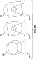
Fig. 10 shows three alternate embodiments for the shape of the outer oven of the improved tortilla toaster.Fig. 10a is a round oven with a tortilla sticking out of it.Fig. 10b is the "D" shaped oven with a tortilla sticking out of it.Fig. 10c is a square oven with a tortilla sticking out of it. -
Fig. 11 shows steps for heating and toasting a tortilla with the improved tortilla toaster.Figure 11 a shows a tortilla being placed in the top of the improved tortilla toaster at its rest position where the rear combination manual rotation lever and switch is higher than the forward combination manual rotation lever and switch.Fig. 11b shows the improved tortilla toaster with the oven turned into its operating mode by placing the forward and rearward combination manual rotation lever and switch of the heater as approximately parallel to the table top (allowing the unit to heat up to toasting temperature) where the bent tab comes in contact with the electromagnet.Fig. 11c shows how the improved tortilla toaster returns to its rest position with the rearward combination manual rotation lever and switch higher than the forward combination manual rotation lever and switch when the timer runs its cycle when the electromagnet releases.Fig. 11d shows the oven assembly barrel or drum rotated forward so that the tortillas slide out of the improved tortilla toaster. -
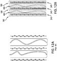
Fig. 12a shows the prior art heating of a tortilla in a typical bread toaster where there is a wire basket designed to hold a piece of bread with exposed heating elements on either side of the basket.Fig. 12b shows the improved tortilla toaster with heating modules with cage guards specifically configured to hold a tortilla a specific distance from said heating modules as well as a mica heating plate with mica thermal diffusers on either said of said mica heating plate that spreads the heat so as evenly to heat and to toast a tortilla. -
Fig. 13 is a schematic that shows the various sizes and spacing of the components and sub-components that comprise the heating modules. -
Fig. 14 is the +5V Power Supply for the improved tortilla toaster. -
Fig. 15 is a perspective rendering of the improved tortilla toaster. -
Fig. 16 is a rendering of DPST Contacts in closed and open positions of the improved tortilla toaster. -
Fig. 17 is an exploded view of the outer oven, inner oven, heating modules, thermal brakes, forward combination manual rotation lever and switch, rearward combination manual rotation lever and switch, and finger guards of the improved tortilla toaster. -
Fig. 18 is an exploded view of the improved tortilla toaster comprised of the left exterior end cap, the left interior end cap, left outer oven enclosure plate, the left thermal brake, the oven assembly with its heating modules in place, right outer oven enclosure plate, the right thermal brake, the right interior end cap, and the right exterior end cap. - The
improved tortilla toaster 100, as shown inFig. 1 , is comprised of a leftend cap unit 120 and a rightend cap unit 140 which are formed with a flat bottom edge for resting on a flat surface such as a tabletop. As shown inFig. 18 , the left end cap is comprised of three pieces: leftouter end cap 123, leftinner end cap 124 and a left outeroven enclosure plate 125. Leftouter end cap 123 and leftinner end cap 124 are joined with molded clips or other attachment means. The left outeroven enclosure plate 125 fits in a recess in leftinner end cap 124. The leftouter enclosure plate 125 has a plurality oftabs 126. The leftouter enclosure plate 125 has a hole in the approximate center of said plate. As shown inFig. 2 ,Fig. 7a , andFig. 17 , the oven is comprised of left and rightthermal brakes left pivot rod 350 and aright pivot rod 355 and anoven assembly 600. As shown inFig. 7a , left insideend cap 120 has aleft socket 530. Theleft pivot rod 350 is seated through said leftouter enclosure plate 125 and intoleft socket 530. As shown inFig. 18 , the rightouter enclosure plate 127 fits in a recess in rightinner end cap 135. The rightouter enclosure plate 127 has a plurality oftabs 128. The rightouter enclosure plate 127 has a hole in the approximate center of said plate. As shown inFigure 7a , rightend cap unit 140 has aright socket 535. Theright pivot rod 355 is seated through said hole in said rightouter enclosure plate 127 and intoright socket 535. On both the left side and right side, theouter enclosure plates right pivot rods - As shown in
Fig. 17 , theoven 600 is comprised of two barrel-like or drum-like structures, anouter oven enclosure 160 and aninner oven enclosure 360. Theinner oven enclosure 360 nests within theouter oven enclosure 160. Theouter oven enclosure 160 on the left side is secured tobracket 550 with rivets or other securing means. The left side ofouter oven enclosure 160 withbracket 550 is secured to left outeroven enclosure plate 125 using a plurality oftabs 126. Theouter oven enclosure 160 on the right side is secured tobracket 555 with rivets or other securing means. The right side of theouter oven enclosure 160 withbracket 555 is secured to the right outeroven enclosure plate 127 using a plurality oftabs 128. - At the heart of the improved tortilla toaster are heating modules as shown assembled in
Fig. 4 and in exploded view inFig. 5 .Fig. 13 provides information on dimensions within the heating module.Fig. 7a shows the seven heating modules in the preferred embodiment of the invention. As you will read below, there are one-sided and two-sided heating modules. Of the seven heating modules, the first and seventh heating modules are one-sided heating modules since outer heating modules only have potential contact with a tortilla on one side. Heating modules in the middle five positions have potential contact with a tortilla on both sides of the modules. - A two-
sided heating module 245, as shown inFig. 5 , is comprised of a leftside cage guard 180, a first micathermal diffuser 310, amica board 330 wrapped withNichrome ribbons 320, a second micathermal diffuser 310, a rightside cage guard 180 and theentire heating module 245 is held together withassembly retainer 250. A one-sided heating module 240 is the same as a two-sided heating module 245 except that the Nichrome ribbons are only present on one side of themica board 330. The paddle-shapedmica board 330 is notched with a plurality ofnotches 342. As shown inFig. 4 andFig. 5 ,mica board 330 hasconnection tab 300.Connection tab 300 haswire lay notches 270.Nichrome lead wire 290 feeds theNichrome ribbons 320 that are wound aroundmica board 330 ending in wire laynotch 270 and wireloop Nichrome terminal 280. On either side ofmica board 330 is micathermal diffuser 310. The heating module ofcage guard 180, micathermal diffuser 310,mica board 330, micathermal diffuser 310,cage guard 180 are held together withassembly retainer 250. As shown inFigs. 7a and17 , the improved tortilla toaster makes use of five two-sided heating modules 245 and two one-sided heating modules 240. - The
inner oven enclosure 360, as shown inFig. 17 , is fabricated with seven regularly spacedbottom slots 565 and seven regularly spaced forward andrearward side slots 575. The left sidethermal brake 170a is secured with rivets or other securing means andbracket 550 to the left edge of theinner oven enclosure 360. As shown inFigs. 7a and17 , a one-sided heating module 240 (active side facing to right side) is installed in the extremeleft slot 565 such thatconnection tab 300 protrudes through the bottom ofinner oven enclosure 360. Five two-sided heating modules 245 are installed in the center five bottom slots such thatconnection tab 300 protrudes through the bottom ofinner oven enclosure 360. As shown inFigs. 7a and17 , a one-sided heating module 240 (active side facing to left side) is installed in the extremeright slot 565 such thatconnection tab 300 protrudes through the bottom ofinner oven enclosure 360. The right sidethermal brake 170b is secured to with rivets or other securing means andbracket 555 to the right edge of theinner oven enclosure 360. As shown inFigs. 7a and17 , an AC power cord comes from an electric source into theright end cap 137 and connects to theDPST Contact 650b mountedRight Plate 127. TheDPST Contact 650a is mounted on the rightthermal brake 170b. Wire leads run from theDPST Contact 650a to the onesided heating module 240 adjacent the rightthermal brake 170b and connects at the wire laynotch 270. Another set of wire leads run from the wire laynotch 270 to thecontrol board 380. The heating modules are powered with wires that run pier to pier from one heating module to the next connected at the wire laynotches 270 on eachheating module control board 380 toelectromagnet 660 mounted on thethermal brake 170b. - As shown in
Fig. 17 , theinner oven assembly 585 is secured in theouter oven enclosure 160 using theleft bracket 550 andright bracket 555. Theretention tab 230 as shown inFigure 4 on eachassembly retainer 250 on eachheating module brackets outer oven enclosure 160 with securing means and the rearward combination manual rotation lever and switch 220 which is also secured to thebrackets outer oven enclosure 160. Sixfinger guards 130 are secured in the forward combination manual rotation lever and switch 110 and rearward combination manual rotation lever andswitch 220. - As shown in
Figs. 7 ,17 , and18 , theouter oven assembly 595 is mounted in the leftend cap unit 120 and rightend cap unit 140 by theleft pivot rod 350 on the leftthermal brake 170a nesting through the left outeroven enclosure plate 125 into theleft socket 530 and theright pivot rod 355 on the rightthermal brake 170b nesting through the right outeroven enclosure plate 127 into theright socket 535. Left and right torsion springs 540, 545 are installed on left andright pivot rods oven assembly 600. - The improved tortilla toaster, as shown in
Fig. 13 , is specifically configured. The thickness, Th, of the two micathermal diffusers 310 along with themica heating plate 330 is about 0.0785 inches. By experimentation, the inventor determined that the optimal distance from the outside of each micathermal diffuser 310 to thecage guard 180, Ow, is about 0.100 inch. By experimentation inventor determined that theloading zone 190 between two opposingcage guards 180, Wslot, is about 0.435 inch. The distance from heating center of onemica heating plate 330 to the adjacent center of mica heating plate (known as the "Pitch"), Phh, is derived to be about 0.800 inch. The diameter of the hot zone, DHZ, was established by experimentation to be about 5.5 inches. The diameter of the mica heater assembly, DHTR, was established by experimentation to be about 6.0 inches. The diameter of the cage guard 180 (here called by the alternate name "wire cloth") was determined by experiment to be about 6.5 inches. - The controls in the improved tortilla toaster are shown in
Figs. 1 ,2 ,3 ,7b ,8 ,9a ,9b 14 ,15 ,17 , and18 .Figs. 1 ,2 ,3 ,7b ,8 ,14 ,15 ,17 , and18 show theadjustment knob 150 mounted on the front of theouter oven enclosure 160. Theknob 150 connects through the outer oven enclosure and attaches to thecontrol board 380. Thecontrol board 380 is mounted on the inside of theouter oven enclosure 160 although theknob 150 includes a LED indicator light above it. On the wire diagramFigure 9b , theadjustment knob 150 connects to the Duration Rotary Switch on thecontrol board 380. The Duration Rotary Switch has either 10 or 16 positions. Thecontrol board 380 is connected to athermistor 625 that protrudes into or has access through an aperture to theinner oven 360 to measure the temperature in theinner oven 360. - The improved tortilla toaster is turned on by rotating the forward combination manual rotation lever and switch 110 or the rearward combination manual rotation lever and switch 220 so that they are about parallel to the table top on the improved tortilla toaster is resting. That rotation brings into
contact DPST contacts bent tab 400 to a position in contact withelectromagnet 660. Connected to AC line power, the microcontroller marked PIC18F13K22 on wire diagramFigure 9a , starts the heating process of theheating modules electromagnet 660 when energized andbent tab 400 keep the improved tortilla toaster in the operating position with the front combination manual rotation lever and switch 110 and rear combination manual rotation lever and switch 220 approximately parallel to the ground or surface on which the improved tortilla toaster.Figure 9a is the toaster control electronics for the improved tortilla toaster.Figure 9b is the circuitry diagram for the improved tortilla toaster. Thepower lead 370 connects to thecontrol board 380. -
Fig. 11 shows the steps of using the improved tortilla toaster.Fig. 11a shows the improved tortilla toaster in its resting position where the forward combination manual rotation lever and switch 110 is rotated a bit and down such that the rearward combination manual rotation lever and switch 220 is a bit up. At this point, the user would load tortillas in the improved tortilla toaster.Fig. 11b shows that by rotating the forward combination manual rotation lever and switch 110 or the rearward combination manual rotation lever or switch 220 so that they are parallel to the table top, the improved tortilla toaster engages and heats.Fig. 11c shows how at the end of the time cycle (when theelectromagnet 660 releases thebent tab 400 and the oven assembly pivots forward and right and leftpivot rods oven assembly 600 to rotate to its rest position) releases the forward combination manual rotation lever and switch 110 and rearward combination manual rotation lever and switch 220 would once again return to a rest position. Infigure 11d , the user may rotate the oven assembly by pressing down the forward combination manual rotation lever and switch 110 or by pulling over the rearward combination manual rotation lever and switch 220 for the heated tortillas to slide from the improved tortilla toaster. After removing the tortillas and with or without assistance from the user theoven assembly 600 would rotate back to its rest position (as shown infigure 11a ) as it is weighted to have a resting position of approximately 30° forward. - This invention has been disclosed in terms of certain embodiments. It will be apparent that many modifications can be made to the disclosed apparatus without departing from the invention.
Claims (25)
- A device for heating tortilla-like food, comprising:- an upright support base (120,140);- a substantially horizontally arranged drum rotatably secured on said support base (120,140);- heating module compartment means (240, 245) arranged in said drum adapted to receive said tortilla-like food,- said heating module compartment means (240,245) arranged transverse to the horizontal rotation axis of said drum and openable from a horizontal surface on said drum;- said heating module compartment means (240,245) adapted to receive said food in said module for heating- an electromagnet (660) affixed in said oven assembly to lock rotation of said drum during heating:-- said drum being selectively rotatable from a first position to receive said food in said heating module compartment means (240,245) to a second position for releasing said food from said heating module compartment means (240,245).
- The device of Claim 1, wherein said support base (120,140) comprises a pair of spaced apart end caps, one on each end of said drum.
- The device of Claim 1, wherein said drum comprises an oven enclosure (160,360) for receiving said heating module compartment means (240,245).
- The device of Claim 3, wherein said drum has lever means (110, 220,660) for controlling the movement of said drum.
- The device of Claim 3, wherein said drum has switch means (150,380,625) for controlling delivery of heat to said heating module compartment means (240,245) .
- The device of Claim 1, wherein said heating compartment module means (240,245) comprises a cage-like assembly consisting of heating resistance wires and diffusing means for evenly spreading the heat created by said wires across a surface adapted to transfer heat from said assembly to said food.
- The device of Claim 6, wherein said cage-like assembly has heating elements and diffusing means arranged to heat both sides of said food.
- The device of Claim 7, wherein said element and diffusing means for one side of said food is spaced from an element and diffusing means for another side of said food and the spacing of said sides is dependent upon the space between said food sides.
- The device of Claim 7, wherein said diffusing means comprises mica thermal diffusers (310).
- The device of Claim 7, wherein said heating elements comprise electrical resistance wires.
- The device of Claim 6, wherein multiple cage-like assemblies are arranged in said drum.
- The device of Claim 6, wherein guard means are provided for said assemblies to avoid burning of a user during operation of the device.
- The device of Claim 6, wherein an electrical circuit in said device connects said heating elements to a source of power.
- The device of Claim 12, wherein a timer in said circuit establishes a cycle for delivering electrical power to said heating elements using electromagnet (660) and bent tab (400).
- The device of Claim 14, where said timer controls release of said drum for movement to said second position.
- The device of Claim 12, wherein said timer cycle is controlled by the positions of said drum .
- The device of Claim 12, wherein said circuit has a control board (380) connected to said cage-like assembly.
- The device of Claim 1, wherein said food is held in said first position when received in said drum and falls freely from said drum when in said second position.
- A combination of device for heating tortilla-like food according to any of the claims 1 to 18 and, in a heating module compartment of said device, a cage-like structure for receiving such tortilla-like food, said cage-like structure comprising spaced apart walls defining an area between said walls for holding such food, and adjacent a first one of said walls an assembly of heating resistance wire and thermal diffusing means overlying said wire.
- The combination of Claim 19, wherein a second assembly of heating resistance wire and thermal diffusing means overlying said wire is adjacent a second wall.
- The combination of Claim 19, wherein the distance (190) between said assemblies is greater than the thickness of the food to be heated and less than the distance necessary for heating said food when it is arranged in said compartment.
- The combination of Claim 19, wherein said diffusing means comprises a mica thermal diffuser (310) and a mica board (330).
- The combination of Claim 19, wherein like assemblies of wire and diffusing means are arranged back to back to define adjacent compartments of heating modules.
- A method for heating tortilla-like food ready for consumption, said method comprising the following steps:- providing an upright heated movable container having a first position arranged with a horizontally arranged opening,- inserting unheated tortilla-like food in said opening,- engaging and heating by rotating forward or rearward combination manual rotation lever and switch (110,220) to the parallel position to the table top- heating said tortilla-like food for a period of time until it is ready for consumption when an electromagnet (660) releases a bent tab (400) and the oven assembly (600) pivots to its rest position- moving said container to a second position traverse to said first position where said ready tortilla-like food will fall by gravity from said opening.
- The method of Claim 24, where container has a timer for selectively setting the time said tortilla-like food is heated, with the additional step of releasing said movable container for movement to said second position when said set time of said timer is reached.
Applications Claiming Priority (2)
| Application Number | Priority Date | Filing Date | Title |
|---|---|---|---|
| US201361785976P | 2013-03-14 | 2013-03-14 | |
| PCT/US2014/029236 WO2014153134A1 (en) | 2013-03-14 | 2014-03-14 | Improved tortilla toaster |
Publications (3)
| Publication Number | Publication Date |
|---|---|
| EP2967257A1 EP2967257A1 (en) | 2016-01-20 |
| EP2967257A4 EP2967257A4 (en) | 2016-10-19 |
| EP2967257B1 true EP2967257B1 (en) | 2019-07-10 |
Family
ID=51581425
Family Applications (1)
| Application Number | Title | Priority Date | Filing Date |
|---|---|---|---|
| EP14769896.3A Active EP2967257B1 (en) | 2013-03-14 | 2014-03-14 | A device and method for heating tortilla-like food |
Country Status (13)
| Country | Link |
|---|---|
| US (2) | US10098504B2 (en) |
| EP (1) | EP2967257B1 (en) |
| CN (1) | CN105163635B (en) |
| AU (1) | AU2014236221B2 (en) |
| BR (1) | BR112015023440B1 (en) |
| CA (1) | CA2905504C (en) |
| CR (1) | CR20150568A (en) |
| ES (1) | ES2750260T3 (en) |
| HK (1) | HK1218847A1 (en) |
| MX (1) | MX365132B (en) |
| RU (1) | RU2668069C2 (en) |
| WO (1) | WO2014153134A1 (en) |
| ZA (1) | ZA201507677B (en) |
Families Citing this family (11)
| Publication number | Priority date | Publication date | Assignee | Title |
|---|---|---|---|---|
| US20210386244A1 (en) * | 2013-03-14 | 2021-12-16 | Elliot Benitez | Tortilla Toaster |
| CA2905504C (en) * | 2013-03-14 | 2021-05-04 | Elliot BENITEZ | Improved tortilla toaster |
| USD808704S1 (en) * | 2015-09-08 | 2018-01-30 | Elliot Benitez | Tortilla toaster |
| US10767902B2 (en) * | 2015-11-13 | 2020-09-08 | Thermasi Llc | Electric resistance radiant furnace with mesh, screen, or honeycomb between panel emitters |
| CN107028513A (en) * | 2017-05-16 | 2017-08-11 | 徐幼君 | A kind of cake oven |
| CN107174138B (en) * | 2017-06-30 | 2019-05-10 | 浙江海迪森胶丸有限公司 | Food process sub-assembly |
| US11078393B2 (en) | 2017-10-16 | 2021-08-03 | Terves, Llc | Non-toxic high-density fluid for completion applications |
| WO2019126349A1 (en) * | 2017-12-20 | 2019-06-27 | Spectrum Brands, Inc. | Analog pulse width modulation temperature control |
| CN212346260U (en) * | 2019-02-26 | 2021-01-15 | 沙克忍者运营有限责任公司 | Cooking system capable of being positioned on a support surface and mountable cooking system |
| CN214595581U (en) | 2020-04-06 | 2021-11-05 | 沙克忍者运营有限责任公司 | Cooking system positionable on a support surface |
| US20230107223A1 (en) * | 2021-10-01 | 2023-04-06 | Xavier G. Gonzalez | Electric taco griller |
Family Cites Families (63)
| Publication number | Priority date | Publication date | Assignee | Title |
|---|---|---|---|---|
| US1551336A (en) * | 1925-08-25 | Electbic toaster | ||
| US1212051A (en) * | 1916-05-23 | 1917-01-09 | George S Gumaer | Bread-toaster. |
| US1471275A (en) * | 1922-08-09 | 1923-10-16 | Elie J Moneuse | Toaster |
| US1697914A (en) * | 1924-01-12 | 1929-01-08 | Frederick E Hummel | Family bread toaster |
| US1717979A (en) * | 1924-02-14 | 1929-06-18 | Frederick E Hummel | Bread toaster |
| US1680768A (en) * | 1924-07-01 | 1928-08-14 | William H Dalton | Electric toaster |
| US1682683A (en) * | 1925-06-27 | 1928-08-28 | Angelo C Parodi | Toaster and broiler |
| US1747239A (en) * | 1929-07-17 | 1930-02-18 | Hauck Albert | Peanut roaster and corn popper |
| US2197221A (en) * | 1935-09-10 | 1940-04-16 | Chicago Flexible Shaft Co | Toaster and the like |
| US2114000A (en) * | 1935-12-21 | 1938-04-12 | Vidaver Maxwell | Electric toaster |
| US2167121A (en) * | 1936-02-19 | 1939-07-25 | Harold J Mccreary | Timing and timing device |
| US2270327A (en) * | 1938-02-03 | 1942-01-20 | Mills John | Method and apparatus for cooking foods |
| US2414081A (en) * | 1944-09-07 | 1947-01-14 | Fed Electric Company Inc | Toaster |
| US2387817A (en) * | 1944-10-02 | 1945-10-30 | Norman Bel Geddes | Automatic toaster |
| US2559444A (en) * | 1945-11-23 | 1951-07-03 | Arthur A Locke | Egg cooker |
| US2582760A (en) * | 1946-07-30 | 1952-01-15 | Schoonmaker Carl | Toaster |
| US2523641A (en) * | 1946-11-08 | 1950-09-26 | Alvarez Patent Corp | Cooking device |
| US2562535A (en) * | 1946-11-16 | 1951-07-31 | Arthur A Johnson | Electric toaster |
| US2693141A (en) | 1951-01-05 | 1954-11-02 | Pratt | Tiltable pop-up toaster |
| US2907267A (en) * | 1952-08-14 | 1959-10-06 | Ernest E Lindsey | Cooker |
| US2788427A (en) * | 1953-01-21 | 1957-04-09 | Fresone Eduardo Francisco | Electric roasters |
| US3092014A (en) * | 1962-02-21 | 1963-06-04 | Arthur J Macchi | Pancake baking apparatus |
| US3421432A (en) * | 1966-10-26 | 1969-01-14 | Hubert M Giepen | Electric broiler |
| US3645196A (en) * | 1970-03-09 | 1972-02-29 | White Castle System | French frying machine having rotary food-conveying drum |
| US3859903A (en) * | 1973-05-14 | 1975-01-14 | Gen Electric | Electric oven toaster toast server mechanism |
| NL7414562A (en) | 1973-11-14 | 1975-05-16 | I T T Ind Belgium Societe Anon | PORTABLE HOUSEHOLD APPLIANCE FOR BAKING FOOD. |
| CA1258879A (en) * | 1986-02-13 | 1989-08-29 | William H. Younger | Electric toaster element |
| DE3628617A1 (en) | 1986-08-22 | 1988-03-03 | Krups Stiftung | Toaster, in particular automatic toaster |
| US4976195A (en) * | 1990-05-10 | 1990-12-11 | Cavazos Amado F | Combination bread and tortilla toaster |
| US5309826A (en) | 1993-07-09 | 1994-05-10 | Ortiz Carlos R | Tortilla toaster apparatus |
| US5584231A (en) * | 1993-09-01 | 1996-12-17 | Deleon; Carlos | Multi-purpose food toaster/warmer |
| DE19515196C2 (en) * | 1995-04-25 | 1998-07-02 | Rolus Borgward Packing Gmbh Ag | Roaster |
| US5765471A (en) * | 1996-10-07 | 1998-06-16 | Monard; Ronald E. | Tortilla warming device |
| FR2759842B1 (en) * | 1997-02-14 | 1999-04-16 | Seb Sa | ELECTRIC APPARATUS FOR GRILLING OR HEATING PLANAR FOOD |
| USD401472S (en) * | 1997-02-17 | 1998-11-24 | Townport Limited | Toaster |
| USD413040S (en) * | 1998-05-07 | 1999-08-24 | Prodesign Technology, Inc. | Toaster |
| US6116150A (en) | 1998-07-29 | 2000-09-12 | Greenfield, Jr.; Walter | Multi-level toaster |
| USD422172S (en) * | 1998-11-05 | 2000-04-04 | Lundar Electric Industrial Co., Ltd. | Roaster |
| USD423280S (en) * | 1998-11-19 | 2000-04-25 | Yu-Yuan Lin | Grill |
| NL1010630C2 (en) * | 1998-11-23 | 2000-05-24 | Stork Pmt | To shape. |
| USD433867S (en) * | 2000-02-22 | 2000-11-21 | Lundar Electric Industrial Co., Ltd. | Oven |
| US6205911B1 (en) | 2000-05-18 | 2001-03-27 | Emilio Ochoa | Toasting apparatus |
| USD451333S1 (en) * | 2000-11-13 | 2001-12-04 | Lundar Electric Industrial Co., Ltd. | Roaster |
| US20020152898A1 (en) * | 2001-04-23 | 2002-10-24 | Hp Intellectual Corp. | Flat bread and tortilla warmer |
| US6546844B1 (en) | 2002-04-12 | 2003-04-15 | Alberto Trevino | Tortilla toaster-like warmer appliance |
| US7094991B2 (en) * | 2003-03-27 | 2006-08-22 | Ijn International, Inc. | Electric food warming system and method |
| US6979803B1 (en) * | 2004-02-27 | 2005-12-27 | Jesse Webb | Taco shell heating apparatus |
| US7351939B2 (en) * | 2004-03-19 | 2008-04-01 | Whirlpool Corporation | Toaster |
| US7047871B1 (en) * | 2004-10-25 | 2006-05-23 | Brett M Christoffel | Electric toaster with expanding tray walls |
| US20080282903A1 (en) * | 2007-05-16 | 2008-11-20 | Ricardo Gonzalez | Tortilla warmer |
| USD568669S1 (en) * | 2007-08-09 | 2008-05-13 | Guney Ithalat Ve Pazarlama A.S | Electrical toaster |
| CN100502744C (en) * | 2007-09-10 | 2009-06-24 | 潘焕东 | Movement for toaster |
| US8069776B2 (en) | 2008-03-31 | 2011-12-06 | Appliance Development Corporation | Toaster |
| US8240246B2 (en) * | 2008-06-02 | 2012-08-14 | Rick Davis | Removable toaster basket with handle |
| FR2950239B1 (en) * | 2009-09-18 | 2011-11-25 | Seb Sa | BREAD RACK WITH SWIVEL LATERAL DOOR |
| US8759720B2 (en) * | 2011-02-02 | 2014-06-24 | Ricomale, Llc | Tortilla warmer control system for controlling the preparation and dispensing of tortillas |
| USD703993S1 (en) * | 2013-02-04 | 2014-05-06 | Hamilton Beach Brands, Inc. | Toaster oven |
| USD808704S1 (en) * | 2015-09-08 | 2018-01-30 | Elliot Benitez | Tortilla toaster |
| CA2905504C (en) * | 2013-03-14 | 2021-05-04 | Elliot BENITEZ | Improved tortilla toaster |
| US9516883B1 (en) * | 2013-07-18 | 2016-12-13 | Star Manufacturing International Inc. | Heating assembly and method for tortilla like food |
| US9675210B2 (en) * | 2013-10-24 | 2017-06-13 | Abdalla S. Abukashef | Flatbread toaster |
| US20170035246A1 (en) * | 2015-08-06 | 2017-02-09 | Esmail Roostaie | Toaster Aid |
| US20170303742A1 (en) * | 2016-04-24 | 2017-10-26 | II Rudy Hayashi Gallego II | Container for Heating Tortillas in a Toaster |
-
2014
- 2014-03-14 CA CA2905504A patent/CA2905504C/en active Active
- 2014-03-14 WO PCT/US2014/029236 patent/WO2014153134A1/en active Application Filing
- 2014-03-14 EP EP14769896.3A patent/EP2967257B1/en active Active
- 2014-03-14 BR BR112015023440-2A patent/BR112015023440B1/en not_active IP Right Cessation
- 2014-03-14 US US14/773,753 patent/US10098504B2/en active Active
- 2014-03-14 ES ES14769896T patent/ES2750260T3/en active Active
- 2014-03-14 AU AU2014236221A patent/AU2014236221B2/en not_active Ceased
- 2014-03-14 RU RU2015143459A patent/RU2668069C2/en active
- 2014-03-14 MX MX2015012489A patent/MX365132B/en active IP Right Grant
- 2014-03-14 CN CN201480023880.2A patent/CN105163635B/en active Active
-
2015
- 2015-10-14 ZA ZA2015/07677A patent/ZA201507677B/en unknown
- 2015-10-15 CR CR20150568A patent/CR20150568A/en unknown
-
2016
- 2016-06-15 HK HK16106908.0A patent/HK1218847A1/en not_active IP Right Cessation
-
2017
- 2017-10-19 US US29/622,814 patent/USD839037S1/en active Active
Non-Patent Citations (1)
| Title |
|---|
| None * |
Also Published As
| Publication number | Publication date |
|---|---|
| ES2750260T3 (en) | 2020-03-25 |
| BR112015023440A2 (en) | 2017-07-18 |
| USD839037S1 (en) | 2019-01-29 |
| MX365132B (en) | 2019-05-23 |
| CR20150568A (en) | 2016-03-15 |
| EP2967257A4 (en) | 2016-10-19 |
| CN105163635A (en) | 2015-12-16 |
| CA2905504C (en) | 2021-05-04 |
| AU2014236221B2 (en) | 2018-10-18 |
| AU2014236221A1 (en) | 2015-11-05 |
| EP2967257A1 (en) | 2016-01-20 |
| CN105163635B (en) | 2019-01-18 |
| RU2015143459A3 (en) | 2018-06-18 |
| CA2905504A1 (en) | 2014-09-25 |
| MX2015012489A (en) | 2016-04-26 |
| US10098504B2 (en) | 2018-10-16 |
| WO2014153134A1 (en) | 2014-09-25 |
| HK1218847A1 (en) | 2017-03-17 |
| US20160045069A1 (en) | 2016-02-18 |
| RU2015143459A (en) | 2017-04-26 |
| ZA201507677B (en) | 2017-01-25 |
| BR112015023440B1 (en) | 2021-03-02 |
| RU2668069C2 (en) | 2018-09-25 |
Similar Documents
| Publication | Publication Date | Title |
|---|---|---|
| EP2967257B1 (en) | A device and method for heating tortilla-like food | |
| US5948301A (en) | Food thermalization device | |
| US6265695B1 (en) | Food thermalization device and method | |
| ES2219875T3 (en) | ELECTRICAL DEVICE FOR TOASTING OR RECALLING A FLAT FOOD. | |
| US20060289426A1 (en) | Electric food warming system and method | |
| WO2015160890A1 (en) | Cooking appliance using thin-film heating element | |
| US20110177215A1 (en) | Cooking apparatus | |
| US20170027381A1 (en) | Cooking appliance with direct contact cooking grate | |
| US20210386244A1 (en) | Tortilla Toaster | |
| US6382085B1 (en) | Cooking appliance particularly useful as a multi-function toaster oven | |
| US20140109773A1 (en) | Device for roasting corn on cob | |
| US4577550A (en) | Toaster | |
| US5839354A (en) | Revolving toaster apparatus | |
| WO2011022049A1 (en) | Commercial toaster apparatus | |
| US20110239871A1 (en) | Toaster with functions of baking breads and cooking foods | |
| GB2533969B (en) | A foodstuff cooking device | |
| KR101899757B1 (en) | Apparatus roaster with rotation up and down roast plate | |
| US20090293738A1 (en) | Food Elevator for a Toaster or Grill | |
| WO1999058036A2 (en) | Food thermalization device | |
| GB2537408A (en) | A low power, rapid toasting device | |
| JPH04132526A (en) | Multipurpose toaster | |
| GB2327337A (en) | Toaster with cover and warming rack | |
| JP2004173944A (en) | Cooking apparatus for skewered food |
Legal Events
| Date | Code | Title | Description |
|---|---|---|---|
| PUAI | Public reference made under article 153(3) epc to a published international application that has entered the european phase |
Free format text: ORIGINAL CODE: 0009012 |
|
| 17P | Request for examination filed |
Effective date: 20151009 |
|
| AK | Designated contracting states |
Kind code of ref document: A1 Designated state(s): AL AT BE BG CH CY CZ DE DK EE ES FI FR GB GR HR HU IE IS IT LI LT LU LV MC MK MT NL NO PL PT RO RS SE SI SK SM TR |
|
| AX | Request for extension of the european patent |
Extension state: BA ME |
|
| DAX | Request for extension of the european patent (deleted) | ||
| A4 | Supplementary search report drawn up and despatched |
Effective date: 20160919 |
|
| RIC1 | Information provided on ipc code assigned before grant |
Ipc: A47J 37/08 20060101AFI20160913BHEP |
|
| STAA | Information on the status of an ep patent application or granted ep patent |
Free format text: STATUS: EXAMINATION IS IN PROGRESS |
|
| 17Q | First examination report despatched |
Effective date: 20170721 |
|
| GRAP | Despatch of communication of intention to grant a patent |
Free format text: ORIGINAL CODE: EPIDOSNIGR1 |
|
| STAA | Information on the status of an ep patent application or granted ep patent |
Free format text: STATUS: GRANT OF PATENT IS INTENDED |
|
| INTG | Intention to grant announced |
Effective date: 20190206 |
|
| GRAS | Grant fee paid |
Free format text: ORIGINAL CODE: EPIDOSNIGR3 |
|
| GRAA | (expected) grant |
Free format text: ORIGINAL CODE: 0009210 |
|
| STAA | Information on the status of an ep patent application or granted ep patent |
Free format text: STATUS: THE PATENT HAS BEEN GRANTED |
|
| AK | Designated contracting states |
Kind code of ref document: B1 Designated state(s): AL AT BE BG CH CY CZ DE DK EE ES FI FR GB GR HR HU IE IS IT LI LT LU LV MC MK MT NL NO PL PT RO RS SE SI SK SM TR |
|
| REG | Reference to a national code |
Ref country code: GB Ref legal event code: FG4D |
|
| REG | Reference to a national code |
Ref country code: CH Ref legal event code: EP Ref country code: AT Ref legal event code: REF Ref document number: 1152663 Country of ref document: AT Kind code of ref document: T Effective date: 20190715 |
|
| REG | Reference to a national code |
Ref country code: DE Ref legal event code: R096 Ref document number: 602014049858 Country of ref document: DE |
|
| REG | Reference to a national code |
Ref country code: IE Ref legal event code: FG4D |
|
| REG | Reference to a national code |
Ref country code: SE Ref legal event code: TRGR |
|
| REG | Reference to a national code |
Ref country code: NL Ref legal event code: MP Effective date: 20190710 |
|
| REG | Reference to a national code |
Ref country code: LT Ref legal event code: MG4D |
|
| REG | Reference to a national code |
Ref country code: NO Ref legal event code: T2 Effective date: 20190710 |
|
| REG | Reference to a national code |
Ref country code: AT Ref legal event code: MK05 Ref document number: 1152663 Country of ref document: AT Kind code of ref document: T Effective date: 20190710 |
|
| REG | Reference to a national code |
Ref country code: GR Ref legal event code: EP Ref document number: 20190403101 Country of ref document: GR Effective date: 20200122 |
|
| PG25 | Lapsed in a contracting state [announced via postgrant information from national office to epo] |
Ref country code: HR Free format text: LAPSE BECAUSE OF FAILURE TO SUBMIT A TRANSLATION OF THE DESCRIPTION OR TO PAY THE FEE WITHIN THE PRESCRIBED TIME-LIMIT Effective date: 20190710 Ref country code: LT Free format text: LAPSE BECAUSE OF FAILURE TO SUBMIT A TRANSLATION OF THE DESCRIPTION OR TO PAY THE FEE WITHIN THE PRESCRIBED TIME-LIMIT Effective date: 20190710 Ref country code: AT Free format text: LAPSE BECAUSE OF FAILURE TO SUBMIT A TRANSLATION OF THE DESCRIPTION OR TO PAY THE FEE WITHIN THE PRESCRIBED TIME-LIMIT Effective date: 20190710 Ref country code: NL Free format text: LAPSE BECAUSE OF FAILURE TO SUBMIT A TRANSLATION OF THE DESCRIPTION OR TO PAY THE FEE WITHIN THE PRESCRIBED TIME-LIMIT Effective date: 20190710 Ref country code: PT Free format text: LAPSE BECAUSE OF FAILURE TO SUBMIT A TRANSLATION OF THE DESCRIPTION OR TO PAY THE FEE WITHIN THE PRESCRIBED TIME-LIMIT Effective date: 20191111 Ref country code: BG Free format text: LAPSE BECAUSE OF FAILURE TO SUBMIT A TRANSLATION OF THE DESCRIPTION OR TO PAY THE FEE WITHIN THE PRESCRIBED TIME-LIMIT Effective date: 20191010 |
|
| PG25 | Lapsed in a contracting state [announced via postgrant information from national office to epo] |
Ref country code: AL Free format text: LAPSE BECAUSE OF FAILURE TO SUBMIT A TRANSLATION OF THE DESCRIPTION OR TO PAY THE FEE WITHIN THE PRESCRIBED TIME-LIMIT Effective date: 20190710 Ref country code: LV Free format text: LAPSE BECAUSE OF FAILURE TO SUBMIT A TRANSLATION OF THE DESCRIPTION OR TO PAY THE FEE WITHIN THE PRESCRIBED TIME-LIMIT Effective date: 20190710 Ref country code: RS Free format text: LAPSE BECAUSE OF FAILURE TO SUBMIT A TRANSLATION OF THE DESCRIPTION OR TO PAY THE FEE WITHIN THE PRESCRIBED TIME-LIMIT Effective date: 20190710 Ref country code: IS Free format text: LAPSE BECAUSE OF FAILURE TO SUBMIT A TRANSLATION OF THE DESCRIPTION OR TO PAY THE FEE WITHIN THE PRESCRIBED TIME-LIMIT Effective date: 20191110 |
|
| REG | Reference to a national code |
Ref country code: ES Ref legal event code: FG2A Ref document number: 2750260 Country of ref document: ES Kind code of ref document: T3 Effective date: 20200325 |
|
| PG25 | Lapsed in a contracting state [announced via postgrant information from national office to epo] |
Ref country code: RO Free format text: LAPSE BECAUSE OF FAILURE TO SUBMIT A TRANSLATION OF THE DESCRIPTION OR TO PAY THE FEE WITHIN THE PRESCRIBED TIME-LIMIT Effective date: 20190710 Ref country code: EE Free format text: LAPSE BECAUSE OF FAILURE TO SUBMIT A TRANSLATION OF THE DESCRIPTION OR TO PAY THE FEE WITHIN THE PRESCRIBED TIME-LIMIT Effective date: 20190710 Ref country code: PL Free format text: LAPSE BECAUSE OF FAILURE TO SUBMIT A TRANSLATION OF THE DESCRIPTION OR TO PAY THE FEE WITHIN THE PRESCRIBED TIME-LIMIT Effective date: 20190710 Ref country code: DK Free format text: LAPSE BECAUSE OF FAILURE TO SUBMIT A TRANSLATION OF THE DESCRIPTION OR TO PAY THE FEE WITHIN THE PRESCRIBED TIME-LIMIT Effective date: 20190710 |
|
| PG25 | Lapsed in a contracting state [announced via postgrant information from national office to epo] |
Ref country code: IS Free format text: LAPSE BECAUSE OF FAILURE TO SUBMIT A TRANSLATION OF THE DESCRIPTION OR TO PAY THE FEE WITHIN THE PRESCRIBED TIME-LIMIT Effective date: 20200224 Ref country code: SM Free format text: LAPSE BECAUSE OF FAILURE TO SUBMIT A TRANSLATION OF THE DESCRIPTION OR TO PAY THE FEE WITHIN THE PRESCRIBED TIME-LIMIT Effective date: 20190710 Ref country code: SK Free format text: LAPSE BECAUSE OF FAILURE TO SUBMIT A TRANSLATION OF THE DESCRIPTION OR TO PAY THE FEE WITHIN THE PRESCRIBED TIME-LIMIT Effective date: 20190710 Ref country code: CZ Free format text: LAPSE BECAUSE OF FAILURE TO SUBMIT A TRANSLATION OF THE DESCRIPTION OR TO PAY THE FEE WITHIN THE PRESCRIBED TIME-LIMIT Effective date: 20190710 |
|
| REG | Reference to a national code |
Ref country code: DE Ref legal event code: R097 Ref document number: 602014049858 Country of ref document: DE |
|
| PLBE | No opposition filed within time limit |
Free format text: ORIGINAL CODE: 0009261 |
|
| STAA | Information on the status of an ep patent application or granted ep patent |
Free format text: STATUS: NO OPPOSITION FILED WITHIN TIME LIMIT |
|
| PG2D | Information on lapse in contracting state deleted |
Ref country code: IS |
|
| 26N | No opposition filed |
Effective date: 20200603 |
|
| PG25 | Lapsed in a contracting state [announced via postgrant information from national office to epo] |
Ref country code: SI Free format text: LAPSE BECAUSE OF FAILURE TO SUBMIT A TRANSLATION OF THE DESCRIPTION OR TO PAY THE FEE WITHIN THE PRESCRIBED TIME-LIMIT Effective date: 20190710 |
|
| PGFP | Annual fee paid to national office [announced via postgrant information from national office to epo] |
Ref country code: GB Payment date: 20200503 Year of fee payment: 7 |
|
| REG | Reference to a national code |
Ref country code: DE Ref legal event code: R119 Ref document number: 602014049858 Country of ref document: DE |
|
| PG25 | Lapsed in a contracting state [announced via postgrant information from national office to epo] |
Ref country code: MC Free format text: LAPSE BECAUSE OF FAILURE TO SUBMIT A TRANSLATION OF THE DESCRIPTION OR TO PAY THE FEE WITHIN THE PRESCRIBED TIME-LIMIT Effective date: 20190710 |
|
| REG | Reference to a national code |
Ref country code: CH Ref legal event code: PL |
|
| REG | Reference to a national code |
Ref country code: BE Ref legal event code: MM Effective date: 20200331 |
|
| PG25 | Lapsed in a contracting state [announced via postgrant information from national office to epo] |
Ref country code: LU Free format text: LAPSE BECAUSE OF NON-PAYMENT OF DUE FEES Effective date: 20200314 |
|
| PG25 | Lapsed in a contracting state [announced via postgrant information from national office to epo] |
Ref country code: DE Free format text: LAPSE BECAUSE OF NON-PAYMENT OF DUE FEES Effective date: 20201001 Ref country code: IE Free format text: LAPSE BECAUSE OF NON-PAYMENT OF DUE FEES Effective date: 20200314 Ref country code: FR Free format text: LAPSE BECAUSE OF NON-PAYMENT OF DUE FEES Effective date: 20200331 Ref country code: CH Free format text: LAPSE BECAUSE OF NON-PAYMENT OF DUE FEES Effective date: 20200331 Ref country code: LI Free format text: LAPSE BECAUSE OF NON-PAYMENT OF DUE FEES Effective date: 20200331 |
|
| PG25 | Lapsed in a contracting state [announced via postgrant information from national office to epo] |
Ref country code: BE Free format text: LAPSE BECAUSE OF NON-PAYMENT OF DUE FEES Effective date: 20200331 |
|
| PGFP | Annual fee paid to national office [announced via postgrant information from national office to epo] |
Ref country code: GR Payment date: 20210212 Year of fee payment: 8 Ref country code: IT Payment date: 20210308 Year of fee payment: 8 Ref country code: FI Payment date: 20210319 Year of fee payment: 8 Ref country code: NO Payment date: 20210208 Year of fee payment: 8 |
|
| PGFP | Annual fee paid to national office [announced via postgrant information from national office to epo] |
Ref country code: SE Payment date: 20210310 Year of fee payment: 8 Ref country code: TR Payment date: 20210225 Year of fee payment: 8 |
|
| PGFP | Annual fee paid to national office [announced via postgrant information from national office to epo] |
Ref country code: ES Payment date: 20210405 Year of fee payment: 8 |
|
| GBPC | Gb: european patent ceased through non-payment of renewal fee |
Effective date: 20210314 |
|
| PG25 | Lapsed in a contracting state [announced via postgrant information from national office to epo] |
Ref country code: GB Free format text: LAPSE BECAUSE OF NON-PAYMENT OF DUE FEES Effective date: 20210314 |
|
| PG25 | Lapsed in a contracting state [announced via postgrant information from national office to epo] |
Ref country code: MT Free format text: LAPSE BECAUSE OF FAILURE TO SUBMIT A TRANSLATION OF THE DESCRIPTION OR TO PAY THE FEE WITHIN THE PRESCRIBED TIME-LIMIT Effective date: 20190710 Ref country code: CY Free format text: LAPSE BECAUSE OF FAILURE TO SUBMIT A TRANSLATION OF THE DESCRIPTION OR TO PAY THE FEE WITHIN THE PRESCRIBED TIME-LIMIT Effective date: 20190710 |
|
| PG25 | Lapsed in a contracting state [announced via postgrant information from national office to epo] |
Ref country code: MK Free format text: LAPSE BECAUSE OF FAILURE TO SUBMIT A TRANSLATION OF THE DESCRIPTION OR TO PAY THE FEE WITHIN THE PRESCRIBED TIME-LIMIT Effective date: 20190710 |
|
| REG | Reference to a national code |
Ref country code: FI Ref legal event code: MAE |
|
| REG | Reference to a national code |
Ref country code: NO Ref legal event code: MMEP |
|
| PG25 | Lapsed in a contracting state [announced via postgrant information from national office to epo] |
Ref country code: FI Free format text: LAPSE BECAUSE OF NON-PAYMENT OF DUE FEES Effective date: 20220314 |
|
| PG25 | Lapsed in a contracting state [announced via postgrant information from national office to epo] |
Ref country code: SE Free format text: LAPSE BECAUSE OF NON-PAYMENT OF DUE FEES Effective date: 20220315 Ref country code: NO Free format text: LAPSE BECAUSE OF NON-PAYMENT OF DUE FEES Effective date: 20220331 |
|
| PG25 | Lapsed in a contracting state [announced via postgrant information from national office to epo] |
Ref country code: GR Free format text: LAPSE BECAUSE OF NON-PAYMENT OF DUE FEES Effective date: 20221006 |
|
| PG25 | Lapsed in a contracting state [announced via postgrant information from national office to epo] |
Ref country code: IT Free format text: LAPSE BECAUSE OF NON-PAYMENT OF DUE FEES Effective date: 20220314 |
|
| REG | Reference to a national code |
Ref country code: ES Ref legal event code: FD2A Effective date: 20230601 |
|
| PG25 | Lapsed in a contracting state [announced via postgrant information from national office to epo] |
Ref country code: ES Free format text: LAPSE BECAUSE OF NON-PAYMENT OF DUE FEES Effective date: 20220315 |