EP2966707A1 - Battery module - Google Patents
Battery module Download PDFInfo
- Publication number
- EP2966707A1 EP2966707A1 EP14760827.7A EP14760827A EP2966707A1 EP 2966707 A1 EP2966707 A1 EP 2966707A1 EP 14760827 A EP14760827 A EP 14760827A EP 2966707 A1 EP2966707 A1 EP 2966707A1
- Authority
- EP
- European Patent Office
- Prior art keywords
- bus bar
- battery
- wire
- upright
- extension
- Prior art date
- Legal status (The legal status is an assumption and is not a legal conclusion. Google has not performed a legal analysis and makes no representation as to the accuracy of the status listed.)
- Granted
Links
- 238000005452 bending Methods 0.000 description 5
- 238000007599 discharging Methods 0.000 description 4
- 239000004020 conductor Substances 0.000 description 3
- RKTYLMNFRDHKIL-UHFFFAOYSA-N copper;5,10,15,20-tetraphenylporphyrin-22,24-diide Chemical class [Cu+2].C1=CC(C(=C2C=CC([N-]2)=C(C=2C=CC=CC=2)C=2C=CC(N=2)=C(C=2C=CC=CC=2)C2=CC=C3[N-]2)C=2C=CC=CC=2)=NC1=C3C1=CC=CC=C1 RKTYLMNFRDHKIL-UHFFFAOYSA-N 0.000 description 2
- 238000012856 packing Methods 0.000 description 2
- HBBGRARXTFLTSG-UHFFFAOYSA-N Lithium ion Chemical compound [Li+] HBBGRARXTFLTSG-UHFFFAOYSA-N 0.000 description 1
- 230000000712 assembly Effects 0.000 description 1
- 238000000429 assembly Methods 0.000 description 1
- 229910001416 lithium ion Inorganic materials 0.000 description 1
- 229910052987 metal hydride Inorganic materials 0.000 description 1
- 238000000034 method Methods 0.000 description 1
- 238000004904 shortening Methods 0.000 description 1
Images


Classifications
-
- H—ELECTRICITY
- H01—ELECTRIC ELEMENTS
- H01M—PROCESSES OR MEANS, e.g. BATTERIES, FOR THE DIRECT CONVERSION OF CHEMICAL ENERGY INTO ELECTRICAL ENERGY
- H01M10/00—Secondary cells; Manufacture thereof
- H01M10/05—Accumulators with non-aqueous electrolyte
- H01M10/052—Li-accumulators
- H01M10/0525—Rocking-chair batteries, i.e. batteries with lithium insertion or intercalation in both electrodes; Lithium-ion batteries
-
- H—ELECTRICITY
- H01—ELECTRIC ELEMENTS
- H01M—PROCESSES OR MEANS, e.g. BATTERIES, FOR THE DIRECT CONVERSION OF CHEMICAL ENERGY INTO ELECTRICAL ENERGY
- H01M10/00—Secondary cells; Manufacture thereof
- H01M10/24—Alkaline accumulators
- H01M10/30—Nickel accumulators
-
- H—ELECTRICITY
- H01—ELECTRIC ELEMENTS
- H01M—PROCESSES OR MEANS, e.g. BATTERIES, FOR THE DIRECT CONVERSION OF CHEMICAL ENERGY INTO ELECTRICAL ENERGY
- H01M50/00—Constructional details or processes of manufacture of the non-active parts of electrochemical cells other than fuel cells, e.g. hybrid cells
- H01M50/20—Mountings; Secondary casings or frames; Racks, modules or packs; Suspension devices; Shock absorbers; Transport or carrying devices; Holders
- H01M50/204—Racks, modules or packs for multiple batteries or multiple cells
- H01M50/207—Racks, modules or packs for multiple batteries or multiple cells characterised by their shape
- H01M50/209—Racks, modules or packs for multiple batteries or multiple cells characterised by their shape adapted for prismatic or rectangular cells
-
- H—ELECTRICITY
- H01—ELECTRIC ELEMENTS
- H01M—PROCESSES OR MEANS, e.g. BATTERIES, FOR THE DIRECT CONVERSION OF CHEMICAL ENERGY INTO ELECTRICAL ENERGY
- H01M50/00—Constructional details or processes of manufacture of the non-active parts of electrochemical cells other than fuel cells, e.g. hybrid cells
- H01M50/50—Current conducting connections for cells or batteries
- H01M50/502—Interconnectors for connecting terminals of adjacent batteries; Interconnectors for connecting cells outside a battery casing
- H01M50/503—Interconnectors for connecting terminals of adjacent batteries; Interconnectors for connecting cells outside a battery casing characterised by the shape of the interconnectors
-
- H—ELECTRICITY
- H01—ELECTRIC ELEMENTS
- H01M—PROCESSES OR MEANS, e.g. BATTERIES, FOR THE DIRECT CONVERSION OF CHEMICAL ENERGY INTO ELECTRICAL ENERGY
- H01M50/00—Constructional details or processes of manufacture of the non-active parts of electrochemical cells other than fuel cells, e.g. hybrid cells
- H01M50/50—Current conducting connections for cells or batteries
- H01M50/543—Terminals
- H01M50/552—Terminals characterised by their shape
- H01M50/553—Terminals adapted for prismatic, pouch or rectangular cells
-
- H—ELECTRICITY
- H01—ELECTRIC ELEMENTS
- H01M—PROCESSES OR MEANS, e.g. BATTERIES, FOR THE DIRECT CONVERSION OF CHEMICAL ENERGY INTO ELECTRICAL ENERGY
- H01M10/00—Secondary cells; Manufacture thereof
- H01M10/04—Construction or manufacture in general
- H01M10/0468—Compression means for stacks of electrodes and separators
-
- Y—GENERAL TAGGING OF NEW TECHNOLOGICAL DEVELOPMENTS; GENERAL TAGGING OF CROSS-SECTIONAL TECHNOLOGIES SPANNING OVER SEVERAL SECTIONS OF THE IPC; TECHNICAL SUBJECTS COVERED BY FORMER USPC CROSS-REFERENCE ART COLLECTIONS [XRACs] AND DIGESTS
- Y02—TECHNOLOGIES OR APPLICATIONS FOR MITIGATION OR ADAPTATION AGAINST CLIMATE CHANGE
- Y02E—REDUCTION OF GREENHOUSE GAS [GHG] EMISSIONS, RELATED TO ENERGY GENERATION, TRANSMISSION OR DISTRIBUTION
- Y02E60/00—Enabling technologies; Technologies with a potential or indirect contribution to GHG emissions mitigation
- Y02E60/10—Energy storage using batteries
-
- Y—GENERAL TAGGING OF NEW TECHNOLOGICAL DEVELOPMENTS; GENERAL TAGGING OF CROSS-SECTIONAL TECHNOLOGIES SPANNING OVER SEVERAL SECTIONS OF THE IPC; TECHNICAL SUBJECTS COVERED BY FORMER USPC CROSS-REFERENCE ART COLLECTIONS [XRACs] AND DIGESTS
- Y02—TECHNOLOGIES OR APPLICATIONS FOR MITIGATION OR ADAPTATION AGAINST CLIMATE CHANGE
- Y02P—CLIMATE CHANGE MITIGATION TECHNOLOGIES IN THE PRODUCTION OR PROCESSING OF GOODS
- Y02P70/00—Climate change mitigation technologies in the production process for final industrial or consumer products
- Y02P70/50—Manufacturing or production processes characterised by the final manufactured product
Definitions
- the present invention relates to a battery module.
- Patent Document 1 discloses one example of a rechargeable battery device that serves as a battery pack including battery modules.
- the rechargeable battery device described in Patent Document 1 includes assemblies of stacked batteries.
- Each assembly of stacked batteries includes a floor plate, a back plate projecting from the floor plate, and a base plate fixed to the floor plate.
- a battery module is mounted on the base plate.
- the battery module contacts the back plate.
- Side plates, which project from the edges of the base plate, sandwich the battery module.
- a packing is arranged on the battery module, and another base plate is arranged on the packing.
- Another battery module is mounted on the base plate. In this manner, the battery modules are stacked.
- Patent Document 1 Japanese Laid-Open Patent Publication No. 2011-54353
- the wire when connecting the stacked battery modules with a wire, the wire is extended from the connection terminal of a lower battery module to the connection terminal of an upper battery module.
- a battery cell or the like may exist on a line connecting the connection terminal of the lower battery module and the connection terminal of the upper battery module.
- the wire needs to be extended around such a battery cell. This increases the length of the wire.
- the bending radius of the wire is large, the space occupied by the bent wire increases.
- the length of the wire increases when an object exists on a line connecting the connection terminal of the battery module to the connection terminal of the electronic component.
- the battery module that solves the above problem includes a battery cell including a connection terminal and a bus bar connected to the connection terminal.
- the bus bar includes an upright portion extending in a direction in which the connection terminal projects.
- the bus bar is connected by a wire to a connected body that is arranged at a location separated from the connection terminal in the extension direction of the upright portion.
- the battery cell is configured to be charged and discharged through the bus bar and the wire.
- a battery pack 10 includes three stacked battery modules 20.
- each battery module 20 includes a plurality of prismatic batteries 22, which serve as battery cells.
- the prismatic batteries 22 are each held by a battery holder 21 and arranged side by side in the thickness-wise direction of the prismatic batteries 22.
- end plates 23 are arranged at the two ends of the prismatic batteries 22 in the direction the prismatic batteries 22 are laid out.
- the prismatic batteries 22 are arranged so that a positive terminal 24 and a negative terminal 25 of adjacent ones of the prismatic batteries 22 are adjacent to each other.
- the prismatic battery 22 is a rechargeable battery such as a lithium-ion rechargeable battery or a nickel-metal hydride battery.
- a first upright bus bar 41 is arranged on the prismatic battery 22 located at a first end of a prismatic battery row in the layout direction of the prismatic batteries 22.
- a second upright bus bar 51 is arranged on the prismatic battery 22 located at a second end of the prismatic battery row in the layout direction of the prismatic batteries 22. More specifically, the first upright bus bar 41 is connected to the positive terminal 24 of the prismatic battery 22 located at the first end of the prismatic battery row, and the second upright bus bar 51 is connected to the negative terminal 25 of the prismatic battery 22 located at the second end of the prismatic battery row.
- the flat bus bar 31, which connects the positive terminal 24 and the negative terminal 25 of the adjacent prismatic batteries 22, is a member that connects the prismatic batteries 22 in series.
- the upright bus bars 41 and 51 are members that connect the battery module 20, in which the prismatic batteries 22 are connected in series, to another battery module 20 or other electronic components. The series-connected prismatic batteries 22 are charged and discharged through the upright bus bars 41 and 51.
- the battery holders 21 hold a mounting plate 61, which serves as a plate member on which electronic components are mounted.
- the mounting plate 61 includes a body 62, which has the form of a tetragonal plate, and extensions 63, which extend in the thickness-wise direction of the body 62 from the two lateral ends of the body 62.
- the mounting plate 61 is arranged above the prismatic batteries 22 (i.e., upper side with respect to stacking direction of battery modules 20).
- a relay 66 is mounted on the mounting plate 61.
- the relay 66 controls the discharging and discharging interruption of the prismatic batteries 22.
- the relay 66 is covered by a rectangular tubular relay cover 67, which has a bottom.
- a flat bus bar 32 which serves as a wire connected to a connection terminal of the relay 66, is arranged in the relay cover 67.
- a battery ECU 68 which controls the prismatic batteries 22, is arranged on the mounting plate 61.
- the battery ECU 68 is covered by a rectangular tubular ECU cover 69, which has a bottom.
- the relay 66 and the battery ECU 68 are electronic components that contribute to the charging and discharging of the prismatic batteries 22 (battery modules 20). Electronic components other than the relay 66 (not shown) are also accommodated in the relay cover 67.
- the mounting plate 61 includes through holes 64 and 65.
- the through hole 64 is opposite to the positive terminal 24 of the prismatic battery 22 located at the first end of the prismatic battery row.
- the through hole 65 is opposite to the negative terminal 25 of the prismatic battery 22 located at the second end of the prismatic battery row. That is, the through holes 64 and 65 are opposite to the terminals on which the upright bus bars 41 and 51 are arranged.
- the prismatic battery 22 includes a battery case 26 and an electrode assembly 27, which is accommodated in the battery case 26.
- the battery case 26 includes a box-shaped body 28, which accommodates the electrode assembly 27, and a lid 29, which has the form of a tetragonal plate and closes an opening of the body 28.
- the lid 29 includes the positive terminal 24 and the negative terminal 25, which serve as connection terminals.
- the projection direction (extension direction) of the positive terminal 24 and the negative terminal 25 is the same as the thickness-wise direction of the lid 29 (height-wise direction of prismatic battery 22).
- the electrode assembly 27 includes a plurality of stacked positive and negative electrodes.
- the positive terminal 24 and the negative terminal 25 are electrically connected to the electrode assembly 27 by a positive conductive member 24a and a negative conductive member 25a, respectively.
- the positive terminal 24 and the negative terminal 25 each include a rod 30, which projects from the inside of the battery case 26 to the outside of the battery case 26. A circumferential surface of a distal end of the rod 30 (end projecting outside battery case 26) is threaded. When a nut N1 is fastened to the threaded surface, the positive terminal 24 and the negative terminal 25 are fixed to the battery case 26.
- the positive terminal 24 and the negative terminal 25 each include a bolt hole 30a, which extends from the distal end of the rod 30 in the axial direction of the rod 30. The wall of the bolt hole 30a is threaded.
- the first upright bus bar 41 includes a cylindrical upright portion 42.
- An extension 43 is arranged at a first axial end 42a of the upright portion 42 and extends in a direction orthogonal to the axial direction of the upright portion 42.
- the extension 43 includes a basal end and a distal end in the direction the extension 43 extends.
- the basal end is connected to the upright portion 42.
- the extension 43 includes a fastening hole 44, which extends in the extension direction of the extension 43 from the distal end.
- the wall of the fastening hole 44 is threaded.
- An end surface 48 of the distal end of the extension 43 (surface to which wire is connected) extends in the projection direction of the positive terminal 24 and the negative terminal 25. In other words, the end surface 48 is substantially parallel to the projection direction.
- the end surface of a second axial end 42b of the upright portion 42 (end opposite to first axial end 42a of upright portion 42) is joined with the positive terminal 24 of the prismatic battery 22. More specifically, a bolt B1, which is inserted from the first axial end 42a of the upright portion 42 through a hole 45 of the upright portion 42, is fastened to the bolt hole 30a in the positive terminal 24 of the prismatic battery 22 so that the upright portion 42 is arranged on the positive terminal 24.
- the upright portion 42 extends from the positive terminal 24 of the prismatic battery 22 in the projection direction of the positive terminal 24 (height-wise direction of prismatic battery 22).
- the upright portion 42 extends through the through hole 64 in the mounting plate 61 so that the first axial end 42a projects from the mounting plate 61.
- the extension 43 of the first upright bus bar 41 extends to where a battery module 20 does not exist above the extension 43, that is, a location on a line that is parallel to the extension direction of the upright portion 42 and does not interfere with a battery module 20.
- the extension 43 extends so that the extension 43 allows a power wire 46 (described below) to extend straight.
- the power wire 46 which serves as a wire, is joined with the end surface 48 of the first upright bus bar 41.
- the power wire 46 is attached to the end surface 48 of the first upright bus bar 41 by inserting a bolt B2 through a connecting member 47, which is arranged on an axial end of the power wire 46, and fastening the bolt B2 to the fastening hole 44 of the extension 43.
- the end surface 48 of the first upright bus bar 41 functions as a connection surface to which the power wire 46 is connected.
- the power wire 46 extends straight in the stacking direction of the battery modules 20 (extension direction of upright portion 42) without being bent. Adjacent ones of the stacked battery modules 20 are electrically connected by each power wire 46.
- the connection subject (connected body) of the first upright bus bar 41 is another battery module 20 stacked on the battery module 20 to which the first upright bus bar 41 is connected, that is, another battery module 20 arranged at a location separated from the positive terminal 24, to which the first upright bus bar 41 is connected, in the extension direction of the upright portion 42.
- the second upright bus bar 51 includes a cylindrical member 52 and a shaft member 53, which is inserted through the cylindrical member 52.
- the cylindrical member 52 and the shaft member 53 form an upright portion. More specifically, the entire second upright bus bar 51 functions as an upright portion.
- the shaft member 53 is a stud bolt that includes two threaded axial ends.
- a first axial end 53a of the shaft member 53 extends through the flat bus bar 32.
- a second axial end 53b of the shaft member 53 is fastened to the bolt hole 30a in the negative terminal 25 of a prismatic battery 22.
- a nut N2 is fastened to the first axial end 53a, which extends through the flat bus bar 32.
- the second upright bus bar 51 is fixed between the negative terminal 25 of the prismatic battery 22 and the flat bus bar 32 and arranged on the negative terminal 25.
- the connection subject (connected body) of the second upright bus bar 51 is the relay 66, which is arranged above the negative terminal 25, that is, arranged at a location separated from the negative terminal 25 in the extension direction of the second upright bus bar 51.
- the first upright bus bar 41 and the second upright bus bar 51 that are arranged upright from the connection terminals of the prismatic batteries 22 (positive terminal 24 and negative terminal 25) correspond to the claimed bus bar.
- the power wire 46 that is connected to the first upright bus bar 41 and connects the battery modules 20 to each other corresponds to the claimed wire.
- the flat bus bar 32 that is connected to the second upright bus bar 51 and connects the battery modules 20 to the relay 66 also corresponds to the claimed wire. More specifically, the claimed wire refers to a conductor including one end connected to the bus bar, which projects from the connection terminal, and another end connected to the connected body.
- the claimed wire also includes a conductor other than a linear conductor.
- the wire L1 needs to be extended around the object.
- the bending radius of the wire L1 increases the amount in which the wire L1 projects from the battery module 20. This enlarges the space necessary for the bent wire L1.
- the bending radius tends to increase in proportion to the thickness of the wire L1.
- the power wire could be thinned to reduce the bending radius.
- the increased resistance of the power wire would increase the Joule loss.
- thinning the power wire is not realistic.
- the first upright bus bar 41 includes the upright portion 42 and the extension 43.
- the location where the power wire 46 is joined with the first upright bus bar 41 may be shifted so that no object exists on a line connecting the two ends of the power wire 46. This allows the power wire 46 to extend straight in the stacking direction of the battery modules 20 without being bent.
- the second upright bus bar 51 is inserted through the through hole 65 of the mounting plate 61 and connected to the flat bus bar 32 on the mounting plate 61.
- the relay 66 on the mounting plate 61 may be easily connected to the prismatic batteries 22.
- the embodiment has the advantages described below.
- the second upright bus bar 51 projects in the projection direction of the connection terminals.
- the connection terminal of the prismatic battery 22 and the connection terminal of the relay 66, which is arranged above the prismatic battery 22, are connected by the second upright bus bar 51 and the wire (flat bus bar 32).
- the flat bus bar 32 is connected to the end of the second upright bus bar 51, which is located above the connection terminal of the prismatic battery 22, so that an object does not exist on a line that connects the two ends of the flat bus bar 32.
- the first upright bus bar 41 includes the extension 43, which extends from the upright portion 42 in a direction orthogonal to the extension direction of the upright portion 42.
- the location where the power wire 46 is joined with the first upright bus bar 41 may be shifted by the extension 43 in the horizontal direction relative to the location of the upright portion 42 (direction intersecting extension direction of upright portion 42). This avoids a situation in which an object exists on a line that connects the two ends of the power wire 46. This reduces the space occupied by the power wire 46.
- the second upright bus bar 51 is inserted through the through hole 65 in the mounting plate 61 and connected to the flat bus bar 32 on the mounting plate 61.
- the electronic components on the mounting plate 61 may be easily connected to the prismatic batteries 22.
- the embodiment may be modified as follows.
- the extension 43 is extended in a direction intersecting the extension direction of the upright portion 42.
- the extension 43 may be extended and inclined relative to a direction orthogonal to the extension direction of the upright portion 42.
- the upright portion 42 and the extension 43 do not have to be cylindrical.
- the upright portion 42 and the extension 43 may have the form of a polygonal tube such as a quadrangular tube and may have another form.
- the second upright bus bar 51 may have another form such as a quadrangular tube.
- the battery components that contribute to charging and discharging the prismatic batteries 22 do not have to be arranged on the mounting plate 61. In such a case, the mounting plate 61 may be omitted.
- the number of battery modules 20 may be changed. Further, there may be only one battery module 20.
- the battery module 20 does not have to include the battery holder 21.
- the battery module 20 may be configured so that only the prismatic batteries 22 are laid out.
- a cylindrical battery or a laminated battery may be used as the battery cell.
- the extension 43 of the first upright bus bar 41 do not have to be arranged so that the axis of the fastening hole 44 intersects the hole 45 of the upright portion 42. This limits interference of the bolt B2 inserted through the fastening hole 44 with the hole 45 of the upright portion 42.
- the upright bus bars 41 and 51 may be arranged on a prismatic battery 22 other than the prismatic batteries 22 that are arranged at the two ends of the prismatic battery row in the layout direction of the prismatic batteries 22.
- the upright bus bars 41 and 51 may be welded to the positive terminal 24 and the negative terminal 25 of the prismatic battery 22. Further, the upright bus bars 41 and 51 may be connected to the positive terminal 24 and the negative terminal 25 through another process.
- the extension 43 does not have to extend to a location where an obstacle (battery module 20) does not exist above the location. Even in such a case, when the extension 43 is extended to the vicinity of a location where an obstacle does not exist above the location, the bending radius of the power wire 46 is reduced and the power wire 46 is shortened. When the battery module 20 includes a through hole that extends in the vertical direction, the extension 43 may be extended to the through hole so that the power wire 46 is inserted through the through hole.
- the flat bus bar 32 may be replaced with a wire.
- the first upright bus bar 41 may be connected to a connected body that is mounted on the mounting plate 61 such as the relay 66.
- the extension 43 extends toward the relay 66, and the extension 43 and the relay 66 are connected by a wire.
- the wire is shorter than when the wire is connected to the upright portion 42.
Landscapes
- Chemical & Material Sciences (AREA)
- Chemical Kinetics & Catalysis (AREA)
- Electrochemistry (AREA)
- General Chemical & Material Sciences (AREA)
- Engineering & Computer Science (AREA)
- Manufacturing & Machinery (AREA)
- Materials Engineering (AREA)
- Connection Of Batteries Or Terminals (AREA)
- Battery Mounting, Suspending (AREA)
Abstract
Description
- The present invention relates to a battery module.
- Patent Document 1 discloses one example of a rechargeable battery device that serves as a battery pack including battery modules. The rechargeable battery device described in Patent Document 1 includes assemblies of stacked batteries. Each assembly of stacked batteries includes a floor plate, a back plate projecting from the floor plate, and a base plate fixed to the floor plate. A battery module is mounted on the base plate. The battery module contacts the back plate. Side plates, which project from the edges of the base plate, sandwich the battery module. A packing is arranged on the battery module, and another base plate is arranged on the packing. Another battery module is mounted on the base plate. In this manner, the battery modules are stacked.
- Patent Document 1:
Japanese Laid-Open Patent Publication No. 2011-54353 - For example, when connecting the stacked battery modules with a wire, the wire is extended from the connection terminal of a lower battery module to the connection terminal of an upper battery module. A battery cell or the like may exist on a line connecting the connection terminal of the lower battery module and the connection terminal of the upper battery module. Thus, the wire needs to be extended around such a battery cell. This increases the length of the wire. Further, when the bending radius of the wire is large, the space occupied by the bent wire increases. In the same manner, if a wire is extended from the connection terminal of a battery module to the connection terminal of an electronic component located above the battery module, the length of the wire increases when an object exists on a line connecting the connection terminal of the battery module to the connection terminal of the electronic component.
- It is an object of the present invention to provide a battery module that is capable of shortening the wire.
- The battery module that solves the above problem includes a battery cell including a connection terminal and a bus bar connected to the connection terminal. The bus bar includes an upright portion extending in a direction in which the connection terminal projects. The bus bar is connected by a wire to a connected body that is arranged at a location separated from the connection terminal in the extension direction of the upright portion. The battery cell is configured to be charged and discharged through the bus bar and the wire.
-
-
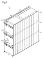
Fig. 1 is a perspective view showing one embodiment of a battery pack. -
Fig. 2 is a perspective view of a battery module in the battery pack shown inFig. 1 . -
Fig. 3 is a cross-sectional view of the battery module shown inFig. 2 . -
Fig. 4 is an enlarged cross-sectional view showing one end of the battery module inFig. 2 . -
Fig. 5 is an enlarged cross-sectional view showing the other end of the battery module inFig. 2 . - One embodiment of a battery module will now be described.
- As shown in
Fig. 1 , abattery pack 10 includes three stackedbattery modules 20. - As shown in
Figs. 2 and 3 , eachbattery module 20 includes a plurality ofprismatic batteries 22, which serve as battery cells. Theprismatic batteries 22 are each held by abattery holder 21 and arranged side by side in the thickness-wise direction of theprismatic batteries 22. In thebattery module 20,end plates 23 are arranged at the two ends of theprismatic batteries 22 in the direction theprismatic batteries 22 are laid out. Theprismatic batteries 22 are arranged so that apositive terminal 24 and anegative terminal 25 of adjacent ones of theprismatic batteries 22 are adjacent to each other. Theprismatic battery 22 is a rechargeable battery such as a lithium-ion rechargeable battery or a nickel-metal hydride battery. - As shown in
Figs. 4 and 5 , thepositive terminal 24 and thenegative terminal 25 of adjacent ones of theprismatic batteries 22 are connected by aflat bus bar 31. A firstupright bus bar 41 is arranged on theprismatic battery 22 located at a first end of a prismatic battery row in the layout direction of theprismatic batteries 22. A secondupright bus bar 51 is arranged on theprismatic battery 22 located at a second end of the prismatic battery row in the layout direction of theprismatic batteries 22. More specifically, the firstupright bus bar 41 is connected to thepositive terminal 24 of theprismatic battery 22 located at the first end of the prismatic battery row, and the secondupright bus bar 51 is connected to thenegative terminal 25 of theprismatic battery 22 located at the second end of the prismatic battery row. - In the
battery module 20, theflat bus bar 31, which connects thepositive terminal 24 and thenegative terminal 25 of the adjacentprismatic batteries 22, is a member that connects theprismatic batteries 22 in series. In thebattery module 20, theupright bus bars battery module 20, in which theprismatic batteries 22 are connected in series, to anotherbattery module 20 or other electronic components. The series-connectedprismatic batteries 22 are charged and discharged through theupright bus bars - As shown in
Fig. 2 , thebattery holders 21 hold amounting plate 61, which serves as a plate member on which electronic components are mounted. Themounting plate 61 includes abody 62, which has the form of a tetragonal plate, andextensions 63, which extend in the thickness-wise direction of thebody 62 from the two lateral ends of thebody 62. Themounting plate 61 is arranged above the prismatic batteries 22 (i.e., upper side with respect to stacking direction of battery modules 20). - A
relay 66 is mounted on themounting plate 61. Therelay 66 controls the discharging and discharging interruption of theprismatic batteries 22. Therelay 66 is covered by a rectangulartubular relay cover 67, which has a bottom. Aflat bus bar 32, which serves as a wire connected to a connection terminal of therelay 66, is arranged in therelay cover 67. Abattery ECU 68, which controls theprismatic batteries 22, is arranged on themounting plate 61. Thebattery ECU 68 is covered by a rectangulartubular ECU cover 69, which has a bottom. Therelay 66 and thebattery ECU 68 are electronic components that contribute to the charging and discharging of the prismatic batteries 22 (battery modules 20). Electronic components other than the relay 66 (not shown) are also accommodated in therelay cover 67. - As shown in
Figs. 4 and 5 , themounting plate 61 includes throughholes hole 64 is opposite to thepositive terminal 24 of theprismatic battery 22 located at the first end of the prismatic battery row. The throughhole 65 is opposite to thenegative terminal 25 of theprismatic battery 22 located at the second end of the prismatic battery row. That is, the throughholes upright bus bars - As shown in
Fig. 3 , theprismatic battery 22 includes abattery case 26 and anelectrode assembly 27, which is accommodated in thebattery case 26. Thebattery case 26 includes a box-shaped body 28, which accommodates theelectrode assembly 27, and alid 29, which has the form of a tetragonal plate and closes an opening of thebody 28. Thelid 29 includes thepositive terminal 24 and thenegative terminal 25, which serve as connection terminals. In the present embodiment, the projection direction (extension direction) of thepositive terminal 24 and thenegative terminal 25 is the same as the thickness-wise direction of the lid 29 (height-wise direction of prismatic battery 22). Theelectrode assembly 27 includes a plurality of stacked positive and negative electrodes. Thepositive terminal 24 and thenegative terminal 25 are electrically connected to theelectrode assembly 27 by a positiveconductive member 24a and a negativeconductive member 25a, respectively. Thepositive terminal 24 and thenegative terminal 25 each include arod 30, which projects from the inside of thebattery case 26 to the outside of thebattery case 26. A circumferential surface of a distal end of the rod 30 (end projecting outside battery case 26) is threaded. When a nut N1 is fastened to the threaded surface, thepositive terminal 24 and thenegative terminal 25 are fixed to thebattery case 26. Thepositive terminal 24 and thenegative terminal 25 each include abolt hole 30a, which extends from the distal end of therod 30 in the axial direction of therod 30. The wall of thebolt hole 30a is threaded. - As shown in
Fig. 4 , the firstupright bus bar 41 includes acylindrical upright portion 42. Anextension 43 is arranged at a firstaxial end 42a of theupright portion 42 and extends in a direction orthogonal to the axial direction of theupright portion 42. Theextension 43 includes a basal end and a distal end in the direction theextension 43 extends. The basal end is connected to theupright portion 42. Theextension 43 includes afastening hole 44, which extends in the extension direction of theextension 43 from the distal end. The wall of thefastening hole 44 is threaded. Anend surface 48 of the distal end of the extension 43 (surface to which wire is connected) extends in the projection direction of thepositive terminal 24 and thenegative terminal 25. In other words, theend surface 48 is substantially parallel to the projection direction. - In the first
upright bus bar 41, the end surface of a secondaxial end 42b of the upright portion 42 (end opposite to firstaxial end 42a of upright portion 42) is joined with thepositive terminal 24 of theprismatic battery 22. More specifically, a bolt B1, which is inserted from the firstaxial end 42a of theupright portion 42 through ahole 45 of theupright portion 42, is fastened to thebolt hole 30a in thepositive terminal 24 of theprismatic battery 22 so that theupright portion 42 is arranged on thepositive terminal 24. Thus, theupright portion 42 extends from thepositive terminal 24 of theprismatic battery 22 in the projection direction of the positive terminal 24 (height-wise direction of prismatic battery 22). Theupright portion 42 extends through the throughhole 64 in the mountingplate 61 so that the firstaxial end 42a projects from the mountingplate 61. Theextension 43 of the firstupright bus bar 41 extends to where abattery module 20 does not exist above theextension 43, that is, a location on a line that is parallel to the extension direction of theupright portion 42 and does not interfere with abattery module 20. Thus, theextension 43 extends so that theextension 43 allows a power wire 46 (described below) to extend straight. - The
power wire 46, which serves as a wire, is joined with theend surface 48 of the firstupright bus bar 41. Thepower wire 46 is attached to theend surface 48 of the firstupright bus bar 41 by inserting a bolt B2 through a connectingmember 47, which is arranged on an axial end of thepower wire 46, and fastening the bolt B2 to thefastening hole 44 of theextension 43. Thus, theend surface 48 of the firstupright bus bar 41 functions as a connection surface to which thepower wire 46 is connected. Thepower wire 46 extends straight in the stacking direction of the battery modules 20 (extension direction of upright portion 42) without being bent. Adjacent ones of the stackedbattery modules 20 are electrically connected by eachpower wire 46. Thus, thebattery modules 20, in which theprismatic batteries 22 are connected in series, are connected in parallel to each other. The connection subject (connected body) of the firstupright bus bar 41 is anotherbattery module 20 stacked on thebattery module 20 to which the firstupright bus bar 41 is connected, that is, anotherbattery module 20 arranged at a location separated from thepositive terminal 24, to which the firstupright bus bar 41 is connected, in the extension direction of theupright portion 42. - As shown in
Fig. 5 , the secondupright bus bar 51 includes a cylindrical member 52 and ashaft member 53, which is inserted through the cylindrical member 52. The cylindrical member 52 and theshaft member 53 form an upright portion. More specifically, the entire secondupright bus bar 51 functions as an upright portion. Theshaft member 53 is a stud bolt that includes two threaded axial ends. A firstaxial end 53a of theshaft member 53 extends through theflat bus bar 32. A secondaxial end 53b of theshaft member 53 is fastened to thebolt hole 30a in thenegative terminal 25 of aprismatic battery 22. A nut N2 is fastened to the firstaxial end 53a, which extends through theflat bus bar 32. Thus, the secondupright bus bar 51 is fixed between thenegative terminal 25 of theprismatic battery 22 and theflat bus bar 32 and arranged on thenegative terminal 25. The connection subject (connected body) of the secondupright bus bar 51 is therelay 66, which is arranged above thenegative terminal 25, that is, arranged at a location separated from thenegative terminal 25 in the extension direction of the secondupright bus bar 51. - In the present embodiment, the first
upright bus bar 41 and the secondupright bus bar 51 that are arranged upright from the connection terminals of the prismatic batteries 22 (positive terminal 24 and negative terminal 25) correspond to the claimed bus bar. Thepower wire 46 that is connected to the firstupright bus bar 41 and connects thebattery modules 20 to each other corresponds to the claimed wire. Theflat bus bar 32 that is connected to the secondupright bus bar 51 and connects thebattery modules 20 to therelay 66 also corresponds to the claimed wire. More specifically, the claimed wire refers to a conductor including one end connected to the bus bar, which projects from the connection terminal, and another end connected to the connected body. The claimed wire also includes a conductor other than a linear conductor. - The operation of the
battery module 20 of the present embodiment will now be described. - As shown in
Fig. 4 , for example, when the connection terminals of the stackedbattery modules 20 are connected to each other by a wire L1 and an object exists on a line that connects the connection terminals of the stackedbattery modules 20, the wire L1 needs to be extended around the object. When the wire L1 cannot be bent at a right angle, the bending radius of the wire L1 increases the amount in which the wire L1 projects from thebattery module 20. This enlarges the space necessary for the bent wire L1. In particular, when a thick wire is used to reduce the resistance of the power wire through which current discharged from theprismatic battery 22 flows, the bending radius tends to increase in proportion to the thickness of the wire L1. The power wire could be thinned to reduce the bending radius. However, the increased resistance of the power wire would increase the Joule loss. Thus, thinning the power wire is not realistic. - In the present embodiment, the first
upright bus bar 41 includes theupright portion 42 and theextension 43. Thus, the location where thepower wire 46 is joined with the firstupright bus bar 41 may be shifted so that no object exists on a line connecting the two ends of thepower wire 46. This allows thepower wire 46 to extend straight in the stacking direction of thebattery modules 20 without being bent. - The second
upright bus bar 51 is inserted through the throughhole 65 of the mountingplate 61 and connected to theflat bus bar 32 on the mountingplate 61. Thus, therelay 66 on the mountingplate 61 may be easily connected to theprismatic batteries 22. - Accordingly, the embodiment has the advantages described below.
- (1) The second
upright bus bar 51 projects in the projection direction of the connection terminals. The connection terminal of theprismatic battery 22 and the connection terminal of therelay 66, which is arranged above theprismatic battery 22, are connected by the secondupright bus bar 51 and the wire (flat bus bar 32). Thus, when an object exists on a line connecting the connection terminal of theprismatic battery 22 and the connection terminal of therelay 66, theflat bus bar 32 is connected to the end of the secondupright bus bar 51, which is located above the connection terminal of theprismatic battery 22, so that an object does not exist on a line that connects the two ends of theflat bus bar 32. This allows the wire (flat bus bar 32) to be shortened and facilitates connecting. - (2) The first
upright bus bar 41 includes theextension 43, which extends from theupright portion 42 in a direction orthogonal to the extension direction of theupright portion 42. The location where thepower wire 46 is joined with the firstupright bus bar 41 may be shifted by theextension 43 in the horizontal direction relative to the location of the upright portion 42 (direction intersecting extension direction of upright portion 42). This avoids a situation in which an object exists on a line that connects the two ends of thepower wire 46. This reduces the space occupied by thepower wire 46. - (3) The second
upright bus bar 51 is inserted through the throughhole 65 in the mountingplate 61 and connected to theflat bus bar 32 on the mountingplate 61. Thus, the electronic components on the mountingplate 61 may be easily connected to theprismatic batteries 22. - The embodiment may be modified as follows.
- The
extension 43 is extended in a direction intersecting the extension direction of theupright portion 42. Theextension 43 may be extended and inclined relative to a direction orthogonal to the extension direction of theupright portion 42. - The
upright portion 42 and theextension 43 do not have to be cylindrical. For example, theupright portion 42 and theextension 43 may have the form of a polygonal tube such as a quadrangular tube and may have another form. In the same manner, the secondupright bus bar 51 may have another form such as a quadrangular tube. - The battery components that contribute to charging and discharging the
prismatic batteries 22 do not have to be arranged on the mountingplate 61. In such a case, the mountingplate 61 may be omitted. - The number of
battery modules 20 may be changed. Further, there may be only onebattery module 20. - The
battery module 20 does not have to include thebattery holder 21. Thebattery module 20 may be configured so that only theprismatic batteries 22 are laid out. - A cylindrical battery or a laminated battery may be used as the battery cell.
- The
extension 43 of the firstupright bus bar 41 do not have to be arranged so that the axis of thefastening hole 44 intersects thehole 45 of theupright portion 42. This limits interference of the bolt B2 inserted through thefastening hole 44 with thehole 45 of theupright portion 42. - The upright bus bars 41 and 51 may be arranged on a
prismatic battery 22 other than theprismatic batteries 22 that are arranged at the two ends of the prismatic battery row in the layout direction of theprismatic batteries 22. - The upright bus bars 41 and 51 may be welded to the
positive terminal 24 and thenegative terminal 25 of theprismatic battery 22. Further, the upright bus bars 41 and 51 may be connected to thepositive terminal 24 and thenegative terminal 25 through another process. - The
extension 43 does not have to extend to a location where an obstacle (battery module 20) does not exist above the location. Even in such a case, when theextension 43 is extended to the vicinity of a location where an obstacle does not exist above the location, the bending radius of thepower wire 46 is reduced and thepower wire 46 is shortened. When thebattery module 20 includes a through hole that extends in the vertical direction, theextension 43 may be extended to the through hole so that thepower wire 46 is inserted through the through hole. - The
flat bus bar 32 may be replaced with a wire. - The first
upright bus bar 41 may be connected to a connected body that is mounted on the mountingplate 61 such as therelay 66. In this case, theextension 43 extends toward therelay 66, and theextension 43 and therelay 66 are connected by a wire. When a location where the wire is connected to the firstupright bus bar 41 is shifted in the extension direction of theupright portion 42, it is possible to avoid a situation in which an object exists on a line that connects the two ends of the wire. Further, since theextension 43 extends toward therelay 66, the wire is shorter than when the wire is connected to theupright portion 42.
Claims (4)
- A battery module comprising:a battery cell including a connection terminal; anda bus bar connected to the connection terminal, wherein the bus bar includes an upright portion extending in a direction in which the connection terminal projects, wherein:the bus bar is connected by a wire to a connected body that is arranged at a location separated from the connection terminal in an extension direction of the upright portion; andthe battery cell is configured to be charged and discharged through the bus bar and the wire.
- The battery module according to claim 1, wherein:the bus bar includes an extension that is connected to the upright portion and extends in a direction intersecting the extension direction of the upright portion; andthe extension includes a basal end and a distal end, which is arranged at an opposite side of the basal end in an extension direction of the extension, wherein the basal end is connected to the upright portion and the distal end is joined with the wire.
- The battery module according to claim 1 or 2, wherein:the connected body is arranged on a plate member; andthe upright portion is inserted through a through hole of the plate member.
- A battery module comprising:a battery cell including a connection terminal; anda bus bar connected to the connection terminal of the battery cell, wherein:the bus bar is configured to be connected to a wire that is connected to a connection subject; andthe bus bar includes a surface configured to extend in a projection direction of the connection terminal and be connected to the wire.
Applications Claiming Priority (2)
| Application Number | Priority Date | Filing Date | Title |
|---|---|---|---|
| JP2013046664A JP5610012B2 (en) | 2013-03-08 | 2013-03-08 | Battery module |
| PCT/JP2014/055919 WO2014136929A1 (en) | 2013-03-08 | 2014-03-07 | Battery module |
Publications (3)
| Publication Number | Publication Date |
|---|---|
| EP2966707A1 true EP2966707A1 (en) | 2016-01-13 |
| EP2966707A4 EP2966707A4 (en) | 2016-04-06 |
| EP2966707B1 EP2966707B1 (en) | 2017-05-10 |
Family
ID=51491436
Family Applications (1)
| Application Number | Title | Priority Date | Filing Date |
|---|---|---|---|
| EP14760827.7A Not-in-force EP2966707B1 (en) | 2013-03-08 | 2014-03-07 | Battery module |
Country Status (4)
| Country | Link |
|---|---|
| US (1) | US9905828B2 (en) |
| EP (1) | EP2966707B1 (en) |
| JP (1) | JP5610012B2 (en) |
| WO (1) | WO2014136929A1 (en) |
Families Citing this family (5)
| Publication number | Priority date | Publication date | Assignee | Title |
|---|---|---|---|---|
| DE102012218162B4 (en) * | 2012-10-04 | 2023-12-14 | Bayerische Motorenwerke Aktiengesellschaft | Energy storage arrangement |
| JP2015115275A (en) * | 2013-12-13 | 2015-06-22 | 株式会社東芝 | Battery module |
| US20180069201A1 (en) * | 2015-03-20 | 2018-03-08 | Dean Shane MARCUS | Battery |
| WO2017158763A1 (en) * | 2016-03-16 | 2017-09-21 | 株式会社東芝 | Battery pack |
| JP7445219B2 (en) * | 2018-06-22 | 2024-03-07 | 株式会社Gsユアサ | Power storage device |
Family Cites Families (11)
| Publication number | Priority date | Publication date | Assignee | Title |
|---|---|---|---|---|
| FR2462031A1 (en) | 1979-07-20 | 1981-02-06 | Ermeto | Battery terminal lead connection - has clamp ring and insulating screw fitting fully over terminal so overall height is not increased |
| US6628102B2 (en) | 2001-04-06 | 2003-09-30 | Microchip Technology Inc. | Current measuring terminal assembly for a battery |
| US7205746B2 (en) | 2001-04-06 | 2007-04-17 | Microchip Technology Inc. | Battery cover assembly having integrated battery condition monitoring |
| KR100696685B1 (en) * | 2005-05-16 | 2007-03-20 | 삼성에스디아이 주식회사 | Secondary battery module |
| JP5285959B2 (en) | 2008-05-27 | 2013-09-11 | 株式会社ケーヒン | Battery control device for battery pack |
| DE102009001514A1 (en) * | 2009-03-12 | 2010-09-16 | Robert Bosch Gmbh | Battery system with an output voltage of more than 60 V DC |
| JP5546815B2 (en) | 2009-08-31 | 2014-07-09 | 株式会社東芝 | Secondary battery device, method for manufacturing secondary battery device, and forklift provided with secondary battery device |
| WO2012101728A1 (en) | 2011-01-25 | 2012-08-02 | パナソニック株式会社 | Battery module and battery assembly used therein |
| KR20120130224A (en) | 2011-01-25 | 2012-11-29 | 파나소닉 주식회사 | Battery module and battery assembly used therein |
| US20140017528A1 (en) | 2011-03-31 | 2014-01-16 | Yuji Uehara | Rack-mount power supply device and battery pack including detachable connector |
| US20130260611A1 (en) * | 2012-04-03 | 2013-10-03 | Jang-Gun Ahn | Battery module |
-
2013
- 2013-03-08 JP JP2013046664A patent/JP5610012B2/en not_active Expired - Fee Related
-
2014
- 2014-03-07 EP EP14760827.7A patent/EP2966707B1/en not_active Not-in-force
- 2014-03-07 US US14/772,212 patent/US9905828B2/en not_active Expired - Fee Related
- 2014-03-07 WO PCT/JP2014/055919 patent/WO2014136929A1/en not_active Ceased
Also Published As
| Publication number | Publication date |
|---|---|
| JP5610012B2 (en) | 2014-10-22 |
| WO2014136929A1 (en) | 2014-09-12 |
| US20160064716A1 (en) | 2016-03-03 |
| JP2014175152A (en) | 2014-09-22 |
| EP2966707B1 (en) | 2017-05-10 |
| EP2966707A4 (en) | 2016-04-06 |
| US9905828B2 (en) | 2018-02-27 |
Similar Documents
| Publication | Publication Date | Title |
|---|---|---|
| KR101445094B1 (en) | Busbar module and power supply apparatus incorporating the same | |
| US20180114960A1 (en) | Battery pack | |
| US10367180B2 (en) | Battery pack | |
| EP2827405A1 (en) | Battery wiring module | |
| US9893340B2 (en) | Battery wiring module | |
| EP3154108B1 (en) | Battery module and battery pack including same | |
| US9905828B2 (en) | Battery module | |
| JP2014238986A (en) | Bus bar module and power supply device | |
| JP5447724B1 (en) | Wiring module | |
| EP3579298A1 (en) | Battery pack and holder | |
| WO2015163126A1 (en) | Wiring module, wiring-module intermediary body, and method for manufacturing wiring module | |
| US11450914B2 (en) | Storage battery unit | |
| JP6593166B2 (en) | Wiring module | |
| US10396322B2 (en) | Electric storage device | |
| US10923292B2 (en) | Wiring module | |
| CN104137298B (en) | electrochemical element assembly | |
| EP2840629A1 (en) | Wiring module | |
| US11764504B2 (en) | Connector | |
| EP2581964A1 (en) | Battery pack | |
| EP3633760A1 (en) | Storage battery unit | |
| US10079407B2 (en) | Support plate for protection module and battery module having the same | |
| JP6094856B2 (en) | Power storage device, vehicle, and connection terminal |
Legal Events
| Date | Code | Title | Description |
|---|---|---|---|
| PUAI | Public reference made under article 153(3) epc to a published international application that has entered the european phase |
Free format text: ORIGINAL CODE: 0009012 |
|
| 17P | Request for examination filed |
Effective date: 20150911 |
|
| AK | Designated contracting states |
Kind code of ref document: A1 Designated state(s): AL AT BE BG CH CY CZ DE DK EE ES FI FR GB GR HR HU IE IS IT LI LT LU LV MC MK MT NL NO PL PT RO RS SE SI SK SM TR |
|
| AX | Request for extension of the european patent |
Extension state: BA ME |
|
| A4 | Supplementary search report drawn up and despatched |
Effective date: 20160304 |
|
| RIC1 | Information provided on ipc code assigned before grant |
Ipc: H01M 2/10 20060101AFI20160229BHEP Ipc: H01M 2/20 20060101ALI20160229BHEP |
|
| DAX | Request for extension of the european patent (deleted) | ||
| GRAP | Despatch of communication of intention to grant a patent |
Free format text: ORIGINAL CODE: EPIDOSNIGR1 |
|
| INTG | Intention to grant announced |
Effective date: 20161121 |
|
| GRAS | Grant fee paid |
Free format text: ORIGINAL CODE: EPIDOSNIGR3 |
|
| GRAA | (expected) grant |
Free format text: ORIGINAL CODE: 0009210 |
|
| AK | Designated contracting states |
Kind code of ref document: B1 Designated state(s): AL AT BE BG CH CY CZ DE DK EE ES FI FR GB GR HR HU IE IS IT LI LT LU LV MC MK MT NL NO PL PT RO RS SE SI SK SM TR |
|
| REG | Reference to a national code |
Ref country code: GB Ref legal event code: FG4D |
|
| REG | Reference to a national code |
Ref country code: AT Ref legal event code: REF Ref document number: 893171 Country of ref document: AT Kind code of ref document: T Effective date: 20170515 Ref country code: CH Ref legal event code: EP |
|
| REG | Reference to a national code |
Ref country code: IE Ref legal event code: FG4D |
|
| REG | Reference to a national code |
Ref country code: DE Ref legal event code: R096 Ref document number: 602014009775 Country of ref document: DE |
|
| REG | Reference to a national code |
Ref country code: NL Ref legal event code: MP Effective date: 20170510 |
|
| REG | Reference to a national code |
Ref country code: LT Ref legal event code: MG4D |
|
| REG | Reference to a national code |
Ref country code: AT Ref legal event code: MK05 Ref document number: 893171 Country of ref document: AT Kind code of ref document: T Effective date: 20170510 |
|
| PG25 | Lapsed in a contracting state [announced via postgrant information from national office to epo] |
Ref country code: LT Free format text: LAPSE BECAUSE OF FAILURE TO SUBMIT A TRANSLATION OF THE DESCRIPTION OR TO PAY THE FEE WITHIN THE PRESCRIBED TIME-LIMIT Effective date: 20170510 Ref country code: FI Free format text: LAPSE BECAUSE OF FAILURE TO SUBMIT A TRANSLATION OF THE DESCRIPTION OR TO PAY THE FEE WITHIN THE PRESCRIBED TIME-LIMIT Effective date: 20170510 Ref country code: HR Free format text: LAPSE BECAUSE OF FAILURE TO SUBMIT A TRANSLATION OF THE DESCRIPTION OR TO PAY THE FEE WITHIN THE PRESCRIBED TIME-LIMIT Effective date: 20170510 Ref country code: NO Free format text: LAPSE BECAUSE OF FAILURE TO SUBMIT A TRANSLATION OF THE DESCRIPTION OR TO PAY THE FEE WITHIN THE PRESCRIBED TIME-LIMIT Effective date: 20170810 Ref country code: AT Free format text: LAPSE BECAUSE OF FAILURE TO SUBMIT A TRANSLATION OF THE DESCRIPTION OR TO PAY THE FEE WITHIN THE PRESCRIBED TIME-LIMIT Effective date: 20170510 Ref country code: ES Free format text: LAPSE BECAUSE OF FAILURE TO SUBMIT A TRANSLATION OF THE DESCRIPTION OR TO PAY THE FEE WITHIN THE PRESCRIBED TIME-LIMIT Effective date: 20170510 Ref country code: GR Free format text: LAPSE BECAUSE OF FAILURE TO SUBMIT A TRANSLATION OF THE DESCRIPTION OR TO PAY THE FEE WITHIN THE PRESCRIBED TIME-LIMIT Effective date: 20170811 |
|
| PG25 | Lapsed in a contracting state [announced via postgrant information from national office to epo] |
Ref country code: IS Free format text: LAPSE BECAUSE OF FAILURE TO SUBMIT A TRANSLATION OF THE DESCRIPTION OR TO PAY THE FEE WITHIN THE PRESCRIBED TIME-LIMIT Effective date: 20170910 Ref country code: RS Free format text: LAPSE BECAUSE OF FAILURE TO SUBMIT A TRANSLATION OF THE DESCRIPTION OR TO PAY THE FEE WITHIN THE PRESCRIBED TIME-LIMIT Effective date: 20170510 Ref country code: BG Free format text: LAPSE BECAUSE OF FAILURE TO SUBMIT A TRANSLATION OF THE DESCRIPTION OR TO PAY THE FEE WITHIN THE PRESCRIBED TIME-LIMIT Effective date: 20170810 Ref country code: SE Free format text: LAPSE BECAUSE OF FAILURE TO SUBMIT A TRANSLATION OF THE DESCRIPTION OR TO PAY THE FEE WITHIN THE PRESCRIBED TIME-LIMIT Effective date: 20170510 Ref country code: NL Free format text: LAPSE BECAUSE OF FAILURE TO SUBMIT A TRANSLATION OF THE DESCRIPTION OR TO PAY THE FEE WITHIN THE PRESCRIBED TIME-LIMIT Effective date: 20170510 Ref country code: PL Free format text: LAPSE BECAUSE OF FAILURE TO SUBMIT A TRANSLATION OF THE DESCRIPTION OR TO PAY THE FEE WITHIN THE PRESCRIBED TIME-LIMIT Effective date: 20170510 Ref country code: LV Free format text: LAPSE BECAUSE OF FAILURE TO SUBMIT A TRANSLATION OF THE DESCRIPTION OR TO PAY THE FEE WITHIN THE PRESCRIBED TIME-LIMIT Effective date: 20170510 |
|
| PG25 | Lapsed in a contracting state [announced via postgrant information from national office to epo] |
Ref country code: EE Free format text: LAPSE BECAUSE OF FAILURE TO SUBMIT A TRANSLATION OF THE DESCRIPTION OR TO PAY THE FEE WITHIN THE PRESCRIBED TIME-LIMIT Effective date: 20170510 Ref country code: SK Free format text: LAPSE BECAUSE OF FAILURE TO SUBMIT A TRANSLATION OF THE DESCRIPTION OR TO PAY THE FEE WITHIN THE PRESCRIBED TIME-LIMIT Effective date: 20170510 Ref country code: CZ Free format text: LAPSE BECAUSE OF FAILURE TO SUBMIT A TRANSLATION OF THE DESCRIPTION OR TO PAY THE FEE WITHIN THE PRESCRIBED TIME-LIMIT Effective date: 20170510 Ref country code: RO Free format text: LAPSE BECAUSE OF FAILURE TO SUBMIT A TRANSLATION OF THE DESCRIPTION OR TO PAY THE FEE WITHIN THE PRESCRIBED TIME-LIMIT Effective date: 20170510 Ref country code: DK Free format text: LAPSE BECAUSE OF FAILURE TO SUBMIT A TRANSLATION OF THE DESCRIPTION OR TO PAY THE FEE WITHIN THE PRESCRIBED TIME-LIMIT Effective date: 20170510 |
|
| REG | Reference to a national code |
Ref country code: DE Ref legal event code: R097 Ref document number: 602014009775 Country of ref document: DE |
|
| PG25 | Lapsed in a contracting state [announced via postgrant information from national office to epo] |
Ref country code: SM Free format text: LAPSE BECAUSE OF FAILURE TO SUBMIT A TRANSLATION OF THE DESCRIPTION OR TO PAY THE FEE WITHIN THE PRESCRIBED TIME-LIMIT Effective date: 20170510 Ref country code: IT Free format text: LAPSE BECAUSE OF FAILURE TO SUBMIT A TRANSLATION OF THE DESCRIPTION OR TO PAY THE FEE WITHIN THE PRESCRIBED TIME-LIMIT Effective date: 20170510 |
|
| PLBE | No opposition filed within time limit |
Free format text: ORIGINAL CODE: 0009261 |
|
| STAA | Information on the status of an ep patent application or granted ep patent |
Free format text: STATUS: NO OPPOSITION FILED WITHIN TIME LIMIT |
|
| 26N | No opposition filed |
Effective date: 20180213 |
|
| PG25 | Lapsed in a contracting state [announced via postgrant information from national office to epo] |
Ref country code: SI Free format text: LAPSE BECAUSE OF FAILURE TO SUBMIT A TRANSLATION OF THE DESCRIPTION OR TO PAY THE FEE WITHIN THE PRESCRIBED TIME-LIMIT Effective date: 20170510 |
|
| REG | Reference to a national code |
Ref country code: CH Ref legal event code: PL |
|
| GBPC | Gb: european patent ceased through non-payment of renewal fee |
Effective date: 20180307 |
|
| PG25 | Lapsed in a contracting state [announced via postgrant information from national office to epo] |
Ref country code: MC Free format text: LAPSE BECAUSE OF FAILURE TO SUBMIT A TRANSLATION OF THE DESCRIPTION OR TO PAY THE FEE WITHIN THE PRESCRIBED TIME-LIMIT Effective date: 20170510 |
|
| REG | Reference to a national code |
Ref country code: BE Ref legal event code: MM Effective date: 20180331 |
|
| REG | Reference to a national code |
Ref country code: IE Ref legal event code: MM4A |
|
| PG25 | Lapsed in a contracting state [announced via postgrant information from national office to epo] |
Ref country code: LU Free format text: LAPSE BECAUSE OF NON-PAYMENT OF DUE FEES Effective date: 20180307 |
|
| PG25 | Lapsed in a contracting state [announced via postgrant information from national office to epo] |
Ref country code: IE Free format text: LAPSE BECAUSE OF NON-PAYMENT OF DUE FEES Effective date: 20180307 |
|
| PG25 | Lapsed in a contracting state [announced via postgrant information from national office to epo] |
Ref country code: CH Free format text: LAPSE BECAUSE OF NON-PAYMENT OF DUE FEES Effective date: 20180331 Ref country code: LI Free format text: LAPSE BECAUSE OF NON-PAYMENT OF DUE FEES Effective date: 20180331 Ref country code: BE Free format text: LAPSE BECAUSE OF NON-PAYMENT OF DUE FEES Effective date: 20180331 Ref country code: GB Free format text: LAPSE BECAUSE OF NON-PAYMENT OF DUE FEES Effective date: 20180307 |
|
| PG25 | Lapsed in a contracting state [announced via postgrant information from national office to epo] |
Ref country code: FR Free format text: LAPSE BECAUSE OF NON-PAYMENT OF DUE FEES Effective date: 20180331 |
|
| PG25 | Lapsed in a contracting state [announced via postgrant information from national office to epo] |
Ref country code: MT Free format text: LAPSE BECAUSE OF NON-PAYMENT OF DUE FEES Effective date: 20180307 |
|
| PG25 | Lapsed in a contracting state [announced via postgrant information from national office to epo] |
Ref country code: TR Free format text: LAPSE BECAUSE OF FAILURE TO SUBMIT A TRANSLATION OF THE DESCRIPTION OR TO PAY THE FEE WITHIN THE PRESCRIBED TIME-LIMIT Effective date: 20170510 |
|
| PG25 | Lapsed in a contracting state [announced via postgrant information from national office to epo] |
Ref country code: PT Free format text: LAPSE BECAUSE OF FAILURE TO SUBMIT A TRANSLATION OF THE DESCRIPTION OR TO PAY THE FEE WITHIN THE PRESCRIBED TIME-LIMIT Effective date: 20170510 |
|
| PG25 | Lapsed in a contracting state [announced via postgrant information from national office to epo] |
Ref country code: HU Free format text: LAPSE BECAUSE OF FAILURE TO SUBMIT A TRANSLATION OF THE DESCRIPTION OR TO PAY THE FEE WITHIN THE PRESCRIBED TIME-LIMIT; INVALID AB INITIO Effective date: 20140307 Ref country code: CY Free format text: LAPSE BECAUSE OF FAILURE TO SUBMIT A TRANSLATION OF THE DESCRIPTION OR TO PAY THE FEE WITHIN THE PRESCRIBED TIME-LIMIT Effective date: 20170510 Ref country code: MK Free format text: LAPSE BECAUSE OF NON-PAYMENT OF DUE FEES Effective date: 20170510 |
|
| PG25 | Lapsed in a contracting state [announced via postgrant information from national office to epo] |
Ref country code: AL Free format text: LAPSE BECAUSE OF FAILURE TO SUBMIT A TRANSLATION OF THE DESCRIPTION OR TO PAY THE FEE WITHIN THE PRESCRIBED TIME-LIMIT Effective date: 20170510 |
|
| REG | Reference to a national code |
Ref country code: DE Ref legal event code: R079 Ref document number: 602014009775 Country of ref document: DE Free format text: PREVIOUS MAIN CLASS: H01M0002100000 Ipc: H01M0050200000 |
|
| PGFP | Annual fee paid to national office [announced via postgrant information from national office to epo] |
Ref country code: DE Payment date: 20230131 Year of fee payment: 10 |
|
| REG | Reference to a national code |
Ref country code: DE Ref legal event code: R119 Ref document number: 602014009775 Country of ref document: DE |
|
| PG25 | Lapsed in a contracting state [announced via postgrant information from national office to epo] |
Ref country code: DE Free format text: LAPSE BECAUSE OF NON-PAYMENT OF DUE FEES Effective date: 20241001 |
|
| PG25 | Lapsed in a contracting state [announced via postgrant information from national office to epo] |
Ref country code: DE Free format text: LAPSE BECAUSE OF NON-PAYMENT OF DUE FEES Effective date: 20241001 |