EP2966533A2 - Add-on-kammer für verbesserte reaktion von gasdruckreglern - Google Patents
Add-on-kammer für verbesserte reaktion von gasdruckreglern Download PDFInfo
- Publication number
- EP2966533A2 EP2966533A2 EP15175509.7A EP15175509A EP2966533A2 EP 2966533 A2 EP2966533 A2 EP 2966533A2 EP 15175509 A EP15175509 A EP 15175509A EP 2966533 A2 EP2966533 A2 EP 2966533A2
- Authority
- EP
- European Patent Office
- Prior art keywords
- compartment
- chamber
- diaphragm
- pressure regulator
- gas pressure
- Prior art date
- Legal status (The legal status is an assumption and is not a legal conclusion. Google has not performed a legal analysis and makes no representation as to the accuracy of the status listed.)
- Withdrawn
Links
- 230000004044 response Effects 0.000 title description 15
- 238000004891 communication Methods 0.000 claims abstract description 6
- 230000001186 cumulative effect Effects 0.000 claims description 6
- 230000007423 decrease Effects 0.000 claims description 6
- 230000001105 regulatory effect Effects 0.000 claims description 5
- 238000000034 method Methods 0.000 claims description 3
- 238000007789 sealing Methods 0.000 claims 2
- 238000006073 displacement reaction Methods 0.000 claims 1
- 230000008859 change Effects 0.000 abstract description 15
- 239000003570 air Substances 0.000 description 40
- 239000012528 membrane Substances 0.000 description 40
- 239000007789 gas Substances 0.000 description 39
- 230000007246 mechanism Effects 0.000 description 8
- 230000007935 neutral effect Effects 0.000 description 7
- 230000029058 respiratory gaseous exchange Effects 0.000 description 7
- 230000008901 benefit Effects 0.000 description 4
- 230000001276 controlling effect Effects 0.000 description 4
- 238000009434 installation Methods 0.000 description 3
- 239000012080 ambient air Substances 0.000 description 2
- 230000003247 decreasing effect Effects 0.000 description 2
- 239000002737 fuel gas Substances 0.000 description 2
- 238000013022 venting Methods 0.000 description 2
- 241000238631 Hexapoda Species 0.000 description 1
- 229910052782 aluminium Inorganic materials 0.000 description 1
- XAGFODPZIPBFFR-UHFFFAOYSA-N aluminium Chemical compound [Al] XAGFODPZIPBFFR-UHFFFAOYSA-N 0.000 description 1
- 230000003190 augmentative effect Effects 0.000 description 1
- 238000006243 chemical reaction Methods 0.000 description 1
- 238000002485 combustion reaction Methods 0.000 description 1
- 238000010276 construction Methods 0.000 description 1
- 239000000356 contaminant Substances 0.000 description 1
- 230000008878 coupling Effects 0.000 description 1
- 238000010168 coupling process Methods 0.000 description 1
- 238000005859 coupling reaction Methods 0.000 description 1
- 238000013461 design Methods 0.000 description 1
- 238000011161 development Methods 0.000 description 1
- 239000006185 dispersion Substances 0.000 description 1
- 235000012489 doughnuts Nutrition 0.000 description 1
- 239000000835 fiber Substances 0.000 description 1
- 239000006260 foam Substances 0.000 description 1
- 239000006261 foam material Substances 0.000 description 1
- 239000000446 fuel Substances 0.000 description 1
- 231100001261 hazardous Toxicity 0.000 description 1
- 238000012423 maintenance Methods 0.000 description 1
- 229910052751 metal Inorganic materials 0.000 description 1
- 239000002184 metal Substances 0.000 description 1
- 239000000203 mixture Substances 0.000 description 1
- 238000012354 overpressurization Methods 0.000 description 1
- 230000008569 process Effects 0.000 description 1
- 238000011084 recovery Methods 0.000 description 1
- 239000004576 sand Substances 0.000 description 1
- 239000003381 stabilizer Substances 0.000 description 1
- 231100000331 toxic Toxicity 0.000 description 1
- 230000002588 toxic effect Effects 0.000 description 1
- 239000002341 toxic gas Substances 0.000 description 1
- 230000001052 transient effect Effects 0.000 description 1
- XLYOFNOQVPJJNP-UHFFFAOYSA-N water Substances O XLYOFNOQVPJJNP-UHFFFAOYSA-N 0.000 description 1
Images


Classifications
-
- G—PHYSICS
- G05—CONTROLLING; REGULATING
- G05D—SYSTEMS FOR CONTROLLING OR REGULATING NON-ELECTRIC VARIABLES
- G05D16/00—Control of fluid pressure
- G05D16/02—Modifications to reduce the effects of instability, e.g. due to vibrations, friction, abnormal temperature, overloading or imbalance
-
- F—MECHANICAL ENGINEERING; LIGHTING; HEATING; WEAPONS; BLASTING
- F16—ENGINEERING ELEMENTS AND UNITS; GENERAL MEASURES FOR PRODUCING AND MAINTAINING EFFECTIVE FUNCTIONING OF MACHINES OR INSTALLATIONS; THERMAL INSULATION IN GENERAL
- F16K—VALVES; TAPS; COCKS; ACTUATING-FLOATS; DEVICES FOR VENTING OR AERATING
- F16K17/00—Safety valves; Equalising valves, e.g. pressure relief valves
- F16K17/20—Excess-flow valves
- F16K17/34—Excess-flow valves in which the flow-energy of the flowing medium actuates the closing mechanism
-
- F—MECHANICAL ENGINEERING; LIGHTING; HEATING; WEAPONS; BLASTING
- F16—ENGINEERING ELEMENTS AND UNITS; GENERAL MEASURES FOR PRODUCING AND MAINTAINING EFFECTIVE FUNCTIONING OF MACHINES OR INSTALLATIONS; THERMAL INSULATION IN GENERAL
- F16K—VALVES; TAPS; COCKS; ACTUATING-FLOATS; DEVICES FOR VENTING OR AERATING
- F16K31/00—Actuating devices; Operating means; Releasing devices
- F16K31/12—Actuating devices; Operating means; Releasing devices actuated by fluid
- F16K31/126—Actuating devices; Operating means; Releasing devices actuated by fluid the fluid acting on a diaphragm, bellows, or the like
- F16K31/1262—Actuating devices; Operating means; Releasing devices actuated by fluid the fluid acting on a diaphragm, bellows, or the like one side of the diaphragm being spring loaded
- F16K31/1264—Actuating devices; Operating means; Releasing devices actuated by fluid the fluid acting on a diaphragm, bellows, or the like one side of the diaphragm being spring loaded with means to allow the side on which the springs are positioned to be altered
-
- G—PHYSICS
- G05—CONTROLLING; REGULATING
- G05D—SYSTEMS FOR CONTROLLING OR REGULATING NON-ELECTRIC VARIABLES
- G05D16/00—Control of fluid pressure
- G05D16/04—Control of fluid pressure without auxiliary power
- G05D16/06—Control of fluid pressure without auxiliary power the sensing element being a flexible membrane, yielding to pressure, e.g. diaphragm, bellows, capsule
- G05D16/063—Control of fluid pressure without auxiliary power the sensing element being a flexible membrane, yielding to pressure, e.g. diaphragm, bellows, capsule the sensing element being a membrane
- G05D16/0675—Control of fluid pressure without auxiliary power the sensing element being a flexible membrane, yielding to pressure, e.g. diaphragm, bellows, capsule the sensing element being a membrane the membrane acting on the obturator through a lever
- G05D16/0697—Control of fluid pressure without auxiliary power the sensing element being a flexible membrane, yielding to pressure, e.g. diaphragm, bellows, capsule the sensing element being a membrane the membrane acting on the obturator through a lever using several membranes
Definitions
- This invention relates to mechanical self-operating spring-loaded commercial regulators for controlling gas pressure delivery.
- Pressure regulators reduce and/or maintain pressure levels to adjust gas pressure delivery over a range of flow demands.
- a gas pressure regulator for regulating a pressure of a gas system includes a first chamber, a first diaphragm separating the first chamber into a first compartment and a second compartment, and a second chamber also known as an add-on chamber, with a second diaphragm separating the second chamber into a third compartment and a fourth compartment.
- the fourth compartment is connected to, and in communication with, the first compartment of the first chamber.
- a movement of the first diaphragm causes a pressure change in the first compartment.
- the movement of the first diaphragm also causes a corresponding movement of the second diaphragm that changes a volume of the fourth compartment.
- One object and feature of an exemplary embodiment described herein is to provide a chamber for improved response of pressure regulators.
- An exemplary embodiment of a second chamber increases the freedom of response of the system, compared to the freedom of response of the pressure regulator alone, and allows the system to react more quickly to instantaneous pressure changes.
- One advantage of an exemplary second chamber described herein is the ability to improve the system response and maintain stable operating conditions without oversizing the vent lines, and incurring the associated costs and required tuning of regulator and venting mechanism components.
- An exemplary second chamber according to the invention can be advantageously sized to minimize the additional height required, and utilize the existing space around the pressure regulator spring tower. Another advantage of the exemplary second chamber described herein is the ability to provide access to the main spring via the safety cap, to set the pressure levels.
- An exemplary embodiment of a second chamber safely improves the response of a gas pressure regulator, especially for high flow capacity commercial and industrial regulators used for fast acting gas fired space and water heaters.
- An exemplary embodiment of the second chamber may also allow faster response of the gas pressure regulator to rapid changes in pressure and flow demands, while maintaining safe and stable operation.
- a pressure regulator may be used to supply a gas at a steady controlled pressure, thereby controlling gas pressure delivery over a range of flow demands.
- a pressure regulator may meet a varying demand flow of fuel gas from burners, heaters, and process equipment for an array of residential, commercial, and industrial applications.
- a pressure regulator such as a mechanical self-operating spring-loaded pressure regulator, may include gas flow controlling elements, a pressure responsive element, a pressure reference element, and safety elements.
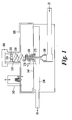
- an exemplary embodiment of a pressure regulator includes a chamber with a membrane or diaphragm 140 separating the chamber into a first compartment 120 and a second compartment 130.
- the second compartment is a pressurized compartment
- the first compartment is an unpressurized or atmospheric side compartment.
- the flexible diaphragm acts as a pressure responsive element, supported and sealed at its perimeter, and coupled to a valve 180.
- a spring tower 110 encasing a spring 150 extends through the unpressurized compartment, and is closed off by a safety cap 100.
- the spring and spring tower may provide a pre-set spring force opposing the diaphragm.
- the safety cap seals the case and ensures that no gas escapes the pressure regulator in the event of a diaphragm break.
- the safety cap also allows for access to the spring for a set-point adjustment by turning, thus moving downward or upward, the internal threaded collar 155, with a central opening 125.
- the movable valve 180 acts as a gas flow controlling element.
- the pressure regulator As the flow entering the pressure regulator increases, the pressure builds in the second compartment, in turn moving the diaphragm 140 against the spring 150 and closing the valve 180. Accordingly, a nearly steady supply pressure can be maintained, provided that the pressure regulator is able to respond quickly enough to the flow changes, in both opening and closing directions. How quickly the regulator responds to the flow changes depends in part on the rate of change of pressure in the second compartment, i.e. how quickly the pressure can be increased or decreased in the second compartment. The rate of change of pressure in the second compartment is further related to the rate of change of pressure in the first compartment, i.e.
- a safety vent or breather 165 is located in the first compartment, and allows air from the first compartment to be vented into a discharge piping system when the diaphragm moves up. Conversely, when the diaphragm moves down, breather air is drawn into the first compartment through the safety vent 165.
- the safety vent incorporates spring loaded two-way flappers and small bleed holes that provide for necessary dampening stability of the diaphragm 140, during operation of the pressure regulator.
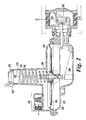
- an exemplary embodiment of a pressure regulator includes elements similar to those of the simplified pressure regulator of Figure 1 .
- a pressure regulator in the exemplary embodiment of Figure 2 , includes a first chamber with a first membrane or diaphragm 240 separating the chamber into a first compartment 220, and a second compartment 230.
- the flexible diaphragm 240 may be supported and sealed at its perimeter, and coupled to a valve mechanism 292.
- the valve mechanism may be actuated by a linkage mechanism 290, which moves as a function of the pressure at the outlet 21, which communicates with second compartment 230 and the corresponding underside of diaphragm 240.
- a vertically extending spring tower 210 encases a spring 250, which extends through the first compartment 220, and is closed off by a safety cap 200, augmented by a tamper evident mechanism 202.
- flow enters the pressure regulator into the second compartment through the gas inlet 11 and valve and orifice 295.
- a safety vent and breather mechanism 260 is located in the first compartment, allowing air from the first compartment to be vented into a discharge piping system when the diaphragm 240 moves up.
- the air in the first compartment 220 of the regulator is either pushed or pulled as the moving diaphragm 240 reacts to the downstream flow characteristics.
- the volume of air present in the first compartment 220 exchanges slowly with ambient surrounding air through the safety vent mechanism 260, and through the associated gas discharge piping.
- the air may work against devices generating resistance such as spring loaded vent stabilizer flappers, and long piping lines.
- the resistance resulting from the vent and discharge system may limit the rate at which air can exit or enter the first compartment, effectively limiting the rate of change of pressure in the first compartment, and thus limiting the response of the regulator to variations in pressure.
- the pipe line size connected to the safety vent 260 may be increased past a certain threshold in order to avoid flutter in the diaphragm. Changes to the safety vent diameter may result in instability or ineffectiveness of the vent system.
- vent flappers and springs associated with the vent line it is possible to change the dampening and tuning characteristics of vent flappers and springs associated with the vent line to also allow for faster breathing of the air into the first compartment.
- These changes to the system may require expensive additional piping or re-piping of existing installations or may need to be accomplished at the regulator factory, likely requiring multiple iterations for the optimal tuning and to avoid instability at particular operating flows and/or an increase in lock-up pressure.
- a second chamber also referred to as an add-on chamber, may be added on to an existing regulator.
- Figures 7A and 7B show exemplary embodiments of existing regulators with second chambers.
- the first chamber may have a volume between 75 and 350 cubic inches. In a non-limiting example, the first chamber may have a height between 1.5 and 3 inches. In an exemplary embodiment, the first membrane may have an outer diameter of 8 to 12 inches.
- the add-on chamber may provide an additional space for air exchanged with the regulator's first compartment to escape into or be drawn from.
- the second chamber may have a volume between 20 and 100 cubic inches.
- the second chamber may have a height between 0.75 inches and 2 inches, and the second membrane may have an outer diameter of 6 to 8 inches.
- the membrane has sufficient space to flex and extend from a neutral position toward the bottom or top of the second chamber.
- a safety vent may be located in the first compartment, allowing air from the first compartment to be vented into a discharge piping system when the diaphragm moves up, and allowing air to be drawn into the first compartment when the diaphragm moves down.
- a second chamber includes a second diaphragm 303.
- a second chamber also referred to as an add-on chamber, may be delimited by a casing 305 and a vent plate 306.
- the diaphragm or membrane 303 may seal and separate the second chamber into a third compartment 335 and a fourth compartment 345.
- springs 302 may be present on either side of the diaphragm 303.
- changes to the outlet pressure of the gas regulator induce movement of the first diaphragm, which in turn causes a corresponding movement of the second diaphragm and changes the pressure in the first compartment at a first rate which matches a second rate of pressure change in the fourth compartment.
- the movement of the first diaphragm causes a corresponding movement of the second diaphragm, with the second diaphragm changing the volume of the fourth compartment and the volume of the third compartment.
- the volume of the fourth compartment increases and the volume of the third compartment decreases.
- the volume of the fourth compartment decreases and the volume of the third compartment increases.
- the presence of the second chamber allows air in the first compartment to communicate with air in the fourth compartment at a rate which is at least equal to, and preferably higher than, a rate at which air enters or exits the first compartment via the vent breather system.
- a first rate of mass flow change in the first compartment may be equal to a second rate of mass flow change in the fourth compartment, caused by the movement of the first diaphragm.
- the first rate of mass flow change in the first compartment may be of the same order of magnitude as a second rate of mass flow change in the fourth compartment caused by the movement of the first diaphragm.
- the second chamber may be sealed by the safety cap 200 of the initial pressure regulator.
- an O-ring 308 may be positioned between the casing 305 and the safety cap 200 to ensure the tightness of the seal.
- an existing pressure regulator also referred to as an off-the-shelf regulator can be modified by removing the safety cap from the spring tower, by connecting the second chamber to the spring tower with an adaptor 309, and by repositioning the safety cap 200 to seal the assembly.
- the O-ring 308 and the safety cap 200 used may be elements from an original pressure regulator being modified.
- the second chamber may be connected to the spring tower 210 of an off-the-shelf pressure regulator, similar to the pressure regulator described above, and shown in Figure 2 .
- Figure 4 shows an exemplary embodiment of the second chamber, connected to a pressure regulator.
- the casing 305 of the fourth compartment 345 may be gas pressure containing and structurally supporting.
- this casing 305 may be connected and sealed onto the first compartment of a pressure regulator by an adaptor 309.
- the adaptor may use a screwed fitting or another appropriate coupling means.
- the adaptor may be a mostly cylindrical piece, connecting the spring tower 210 and the casing 305.
- a protruding lip of the adaptor 311 may also pinch into place the membrane 303 at its inner diameter.
- the membrane may be pinched between the vent plate 306 and the casing 305, both elements being held together by bolts 304, thereby providing a seal 312.
- the second membrane 303 may have an outer diameter between 6 and 8 inches.
- the adaptor may include air breathing openings 301, allowing air from the first compartment to flow into the fourth compartment, and vice-versa, when the first diaphragm moves.
- the area of the air openings located on the adaptor is at least greater than the area of a smallest opening between the first and the fourth compartment.
- the area of the air openings may be referred to as an opening flow area, opening surface area, or opening area, all of which refer to the area of through holes present in the cross-section of an exemplary embodiment.
- the flow direction is substantially perpendicular to a plane in which the openings are present.
- the smallest opening is the opening 225 located at the center of a spring adjustment button 255.
- the area of opening 225 is 0.25 square inches.
- opening 225 is sized to provide an engagement for a square drive tool which allows for turning the spring adjustment button 255, and for setting the outlet pressure.
- the air openings located on the adaptor have a combined opening area between 0.25 square inches and 0.6 square inches, preferably 0.38 square inches.
- the air openings may be two holes with a diameter of at least 0.4 inches. In an alternate embodiment, the air openings may be three or four holes with a diameter of at least 0.4 inches.
- the third compartment 335 of the second chamber may be delimited by vent plate 306, and vented to ambient air.
- this third compartment 335 may be screened and protected from the entry of contaminants such as dirt, weather driven moisture or moving creatures such as insects, by the vented plate 306.
- the vented plate 306 may include openings 316, which allow air to freely enter or exit the third compartment 335.
- the vent holes may be covered by screens or meshes.
- the vent holes may have a minimum cumulative flow area of 0.25 square inches, with a preferred cumulative flow area of 0.38 square inches.
- the vent holes may have a cumulative flow area which is at least equal to the flow area of center opening 225. In an alternative embodiment, the vent holes may be evenly distributed over the vent plate. In yet another alternative embodiment, the vent holes may be circular, with a maximum diameter of substantially 0.1 inches. In an exemplary embodiment, the vent holes may have a minimum cumulative flow area which permits air breathing by movement of the second membrane to the atmosphere, at the same flow rate as the rate of air breathing through the air openings of the adaptor. In an exemplary embodiment, there may be a slight gap 307 between the vent plate and the outer surface of the spring tower 210.
- the vent plate 306 may also act as a support for the flexible diaphragm 303, supporting the diaphragm to avoid a rupture at a maximum emergency pressure of 25 psig.
- the vent plate 306 may be made of aluminum.
- the vent plate may be strong enough to support the second diaphragm pushing against the vent plate with up to 25 psig.
- the maximum pressure which can be supported by the second diaphragm is at least 200 psi, significantly higher than the 25 psig maximum emergency pressure of the regulator.
- the membrane may be donut shaped.
- flexible membrane 303 may be suspended in a neutral and mid-way position in the add-on chamber.
- opposing springs 302 may be used to push lightly on each side of the membrane.
- the springs 302 may be wire wound or made of a soft foam material. In alternative embodiments other means of restoring the membrane to its neutral position may be used, including plastic or metal leaf springs.
- the membrane 303 itself may provide the functions of one or both of these neutral position return springs 302, whereas the inherent structure of the membrane may include means to return the membrane to its neutral position, such as concentric convolutions.
- the membrane is both strong and flexible, with adequate dimensions.
- the membrane may be an elastomeric membrane with molded concentric convolutions, fiber re-enforced, thin and flexible for optimum reaction, but very strong when pressurized and pushed against the vent plate.
- membrane 303 may be a wave diaphragm.
- the accuWAVETM diaphragm may be used for the second membrane.
- the second membrane may exceed the burst strength requirements for gas regulator applications.
- the second membrane may have over forty years of life on a gas meter on an average American home installation.
- the membrane 303 may be pulled or pushed away from its neutral position both freely and quickly.
- the reactiveness of the membrane 303 may be due to its flexible nature, to the presence of light springs 302, and to the vented plate 306 which allows air in the atmospheric-side compartment to exchange easily with the ambient surroundings.
- the membrane 303 may be protected from rupture by being backed up and supported by the casing 305 on one side, and the vent plate 306 or screen wire on another side.
- the volume of air in the first compartment of the pressure regulator may rapidly enter or exit the fourth compartment of the second chamber, instead of slowly entering or exiting via the vent breather system 260.
- the second chamber allows the regulator to safely provide a more constant supply pressure during transient periods when fast demand load changes occur.
- a second chamber permits the quick and direct response of the regulator's moving parts to any rapid flow and pressure demand changes occurring in downstream piping, valving, and/or gas consuming equipment.
- An exemplary embodiment of the second chamber allows for a safe but improved regulator response, instead of simply exposing the regulator's atmospheric side to ambient air.
- a gas may escape to ambient surroundings.
- the gas present in the pressure regulator system may be toxic or harmful.
- the flexible membrane 303 may contain the gas within the fourth compartment and the first compartment.
- the flexible membrane 303 may force the escaped gas to travel through the required vent piping to a safe dispersion location.
- an exemplary embodiment of the second chamber may prevent direct outflow by directing the flow to the vent system 260.
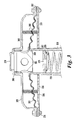
- Figures 5 and 6 show alternative embodiments of a second chamber.
- an alternate exemplary embodiment of a second chamber is shown, and may be connected to a spring tower 210 including a spring 250 by threads 415, or any other connecting means.
- the add-on chamber includes a casing 406, with the outer diameter of the membrane which may be fixed by pinching between the casing 406 and the safety cap 400, and by having a seal such as an O-ring 414.
- the safety cap 400 can be threaded onto the casing 406 by means such as threads 413.
- the exemplary embodiment of Figure 5 further includes a second membrane 403, and screened vents 401.
- the fourth compartment 445 is separated from the third compartment 435 by the membrane 403.
- the shape of this membrane is a cylindrical boot with annular convolutions and end closed off near the threads 415.
- breathing openings 401 allow air from the third compartment to exchange freely with the atmosphere, when the first diaphragm moves and which causes the membrane 403 to move.
- the openings 401 are screen covered to prevent debris from the atmosphere to enter the system.
- a tube 425 acts as a vent plate to prevent the membrane 403 from moving too much or collapsing without recovery, always allowing the membrane 403 to return to a neutral position.
- the tube 425 may be made of a screen mesh or a perforated tube with multiple holes. The paths for air movement are shown in Figure 5 by two-headed arrows in compartments 445 and 435.
- the membrane 403 allows air pressure in the regulator's first compartment to quickly equalize with the atmospheric pressure by moving both axially and radially, in either direction. In this exemplary embodiment, no mass crosses the membrane boundary. In the exemplary embodiment shown in Figure 5 , air in the first compartment 220 communicates directly with the air in the fourth compartment 445 through the center hole 225 in the spring adjustment button 255.
- the add-on chamber device may be removed as a whole by unscrewing at threads 415.
- the second chamber includes a casing 506, a membrane 503, along with restorative means 502, such as springs or foam, and a vent plate 516.
- vent plate 516 may be a wire mesh or a perforated plate, and provides a backup support for the membrane in the event of over-pressurization.
- Screened vent 501 prevents bugs and outside debris from entering the third compartment 535.
- the orientation of the screened vent 501 may be configured to best avoid elements such as rain, sleet, snow or sand from entering the system.
Landscapes
- Engineering & Computer Science (AREA)
- Physics & Mathematics (AREA)
- General Engineering & Computer Science (AREA)
- Fluid Mechanics (AREA)
- General Physics & Mathematics (AREA)
- Automation & Control Theory (AREA)
- Mechanical Engineering (AREA)
- Control Of Fluid Pressure (AREA)
- Safety Valves (AREA)
Applications Claiming Priority (1)
| Application Number | Priority Date | Filing Date | Title |
|---|---|---|---|
| US14/324,975 US9658625B2 (en) | 2014-07-07 | 2014-07-07 | Add-on chamber for improved response of gas pressure regulators |
Publications (2)
| Publication Number | Publication Date |
|---|---|
| EP2966533A2 true EP2966533A2 (de) | 2016-01-13 |
| EP2966533A3 EP2966533A3 (de) | 2016-06-01 |
Family
ID=54007461
Family Applications (1)
| Application Number | Title | Priority Date | Filing Date |
|---|---|---|---|
| EP15175509.7A Withdrawn EP2966533A3 (de) | 2014-07-07 | 2015-07-06 | Add-on-kammer für verbesserte reaktion von gasdruckreglern |
Country Status (12)
| Country | Link |
|---|---|
| US (1) | US9658625B2 (de) |
| EP (1) | EP2966533A3 (de) |
| JP (1) | JP6615512B2 (de) |
| KR (1) | KR20160005653A (de) |
| CN (1) | CN105240581B (de) |
| AU (1) | AU2015202817B2 (de) |
| BR (1) | BR102015013246B1 (de) |
| CA (1) | CA2895723C (de) |
| CL (1) | CL2015001898A1 (de) |
| HK (1) | HK1218440A1 (de) |
| MX (1) | MX349498B (de) |
| SG (1) | SG10201505065XA (de) |
Families Citing this family (9)
| Publication number | Priority date | Publication date | Assignee | Title |
|---|---|---|---|---|
| US9658625B2 (en) * | 2014-07-07 | 2017-05-23 | Sensus Usa Inc. | Add-on chamber for improved response of gas pressure regulators |
| CA2976285C (en) * | 2015-02-23 | 2024-11-12 | Ifd Technologies Inc. | INTEGRATED FAULT MONITORING DEVICE FOR ELECTRICAL EQUIPMENT |
| EA030988B1 (ru) * | 2016-04-08 | 2018-10-31 | Акрам Ахмед Оглы Амрахлы | Система электронного регулирования давления газа |
| US20190064855A1 (en) * | 2017-08-23 | 2019-02-28 | Marshall Excelsior Co. | Pressure regulator vent guard and method of use |
| CN109854951A (zh) * | 2018-12-24 | 2019-06-07 | 涿州滨海燃气有限公司 | 高压干线压力分级利用系统 |
| CN111734864B (zh) * | 2020-07-06 | 2024-09-24 | 宁波戴维医疗器械股份有限公司 | 一种气体混合装置及医疗设备 |
| IT202000017599A1 (it) * | 2020-07-20 | 2022-01-20 | Caleffi Spa | Riduttore di pressione a membrana |
| CN115751192B (zh) * | 2022-11-30 | 2025-04-25 | 山东万罗信和控制工程有限公司 | 蒸汽管道专用调节阀系统 |
| CN115823500B (zh) * | 2023-02-13 | 2023-05-05 | 成都秦川物联网科技股份有限公司 | 基于智慧燃气的燃气入户压力调控方法和物联网系统 |
Family Cites Families (32)
| Publication number | Priority date | Publication date | Assignee | Title |
|---|---|---|---|---|
| US1484394A (en) * | 1920-12-04 | 1924-02-19 | Jenkins Alexander Frederick | Pressure-translating device |
| US2002884A (en) * | 1933-07-05 | 1935-05-28 | Air Reduction | Gas regulator |
| GB447519A (en) | 1934-12-10 | 1936-05-20 | Marvin Henry Grove | Pressure regulator |
| US2685300A (en) * | 1948-12-09 | 1954-08-03 | Nat Welding Equipment Co | Valve control |
| US2731026A (en) * | 1952-07-11 | 1956-01-17 | Reynolds Gas Regulator Company | Fluid pressure regulator |
| FR1096827A (fr) | 1953-06-12 | 1955-06-27 | Spirotechnique | Appareil automatique de réanimation |
| US3032054A (en) * | 1959-04-13 | 1962-05-01 | Fisher Governor Co | Pressure regulator construction |
| US3256903A (en) * | 1961-11-21 | 1966-06-21 | Ingeniors N Fliesberg Ab Fa | Vacuum regulator |
| FR1428174A (fr) | 1965-02-23 | 1966-02-11 | American Meter Co | Régulateur de pression |
| US3443583A (en) * | 1967-11-27 | 1969-05-13 | Webb James E | High impact pressure regulator |
| GB1220467A (en) | 1968-03-11 | 1971-01-27 | Bryan Donkin Co Ltd | Improvements in or relating to gas pressure regulators |
| US3623506A (en) * | 1969-09-22 | 1971-11-30 | Rockwell Mfg Co | Service regulator with high-low pressure cutoff device |
| US3711236A (en) * | 1971-08-02 | 1973-01-16 | Emerson Electric Co | Gas burner control device with low pressure cutoff |
| US3722536A (en) * | 1971-12-17 | 1973-03-27 | Singer Co | Monitor pressure regulator assembly |
| US4067355A (en) * | 1976-04-26 | 1978-01-10 | Textron Inc. | Gas pressure regulator having high and low pressure shut-off means |
| JPS5850016A (ja) * | 1981-09-18 | 1983-03-24 | Matsushita Electric Ind Co Ltd | ガス圧力制御器 |
| US4497339A (en) * | 1982-08-16 | 1985-02-05 | The Gillette Company | Two-stage pressure regulator |
| DE3318896A1 (de) * | 1983-05-25 | 1984-11-29 | Robert 8998 Lindenberg Messmer | Gasdruckregler |
| DE3836878C2 (de) | 1988-10-29 | 1996-12-19 | Gok Gmbh & Co Kg | Sicherheitsabsperrventil |
| US5009245A (en) * | 1989-05-19 | 1991-04-23 | M&Fc Holding Company, Inc. | Pressure regulator |
| US5427143A (en) * | 1994-04-22 | 1995-06-27 | Maracchi; Giorgio | Gas flow and pressure regulation and control station |
| US5709239A (en) * | 1994-11-04 | 1998-01-20 | Macalello; Frank | Automatic shut-off safety device |
| JP3833323B2 (ja) * | 1997-01-07 | 2006-10-11 | Smc株式会社 | 減圧弁 |
| US6536533B2 (en) * | 2000-03-27 | 2003-03-25 | Victaulic Company Of America | Low pressure actuator for dry sprinkler system |
| US7487792B2 (en) * | 2003-12-25 | 2009-02-10 | Asahi Organic Chemical Industry Co., Ltd. | Constant flow valve |
| JP5004553B2 (ja) * | 2006-11-08 | 2012-08-22 | 旭有機材工業株式会社 | 定流量弁 |
| AU2008242690B2 (en) * | 2007-04-20 | 2011-09-15 | Fisher Controls International Llc | Secondary seat for gas regulator |
| US8336574B2 (en) * | 2007-04-20 | 2012-12-25 | Fisher Controls International Llc | Pressure averaging sense tube for gas regulator |
| CN101663628B (zh) * | 2007-04-20 | 2012-02-29 | 费希尔控制产品国际有限公司 | 具有改进的增压性能的维护调节器 |
| JP5232850B2 (ja) * | 2007-04-20 | 2013-07-10 | フィッシャー コントロールズ インターナショナル リミテッド ライアビリティー カンパニー | ガスレギュレータの流れブースト用のカートリッジ |
| US8534315B2 (en) * | 2008-05-16 | 2013-09-17 | Fisher Controls International Llc | Diaphragm assemblies for use with fluid control devices |
| US9658625B2 (en) * | 2014-07-07 | 2017-05-23 | Sensus Usa Inc. | Add-on chamber for improved response of gas pressure regulators |
-
2014
- 2014-07-07 US US14/324,975 patent/US9658625B2/en not_active Expired - Fee Related
-
2015
- 2015-05-25 AU AU2015202817A patent/AU2015202817B2/en not_active Ceased
- 2015-06-08 BR BR102015013246-8A patent/BR102015013246B1/pt not_active IP Right Cessation
- 2015-06-23 CA CA2895723A patent/CA2895723C/en active Active
- 2015-06-26 SG SG10201505065XA patent/SG10201505065XA/en unknown
- 2015-07-02 CL CL2015001898A patent/CL2015001898A1/es unknown
- 2015-07-03 CN CN201510389134.1A patent/CN105240581B/zh not_active Expired - Fee Related
- 2015-07-03 MX MX2015008719A patent/MX349498B/es active IP Right Grant
- 2015-07-03 KR KR1020150095504A patent/KR20160005653A/ko not_active Ceased
- 2015-07-06 EP EP15175509.7A patent/EP2966533A3/de not_active Withdrawn
- 2015-07-06 JP JP2015135381A patent/JP6615512B2/ja not_active Expired - Fee Related
-
2016
- 2016-06-07 HK HK16106488.8A patent/HK1218440A1/zh unknown
Non-Patent Citations (1)
| Title |
|---|
| None |
Also Published As
| Publication number | Publication date |
|---|---|
| EP2966533A3 (de) | 2016-06-01 |
| AU2015202817A1 (en) | 2016-01-21 |
| CN105240581A (zh) | 2016-01-13 |
| US20160004260A1 (en) | 2016-01-07 |
| MX2015008719A (es) | 2016-03-16 |
| US9658625B2 (en) | 2017-05-23 |
| CN105240581B (zh) | 2019-05-17 |
| JP2016021233A (ja) | 2016-02-04 |
| SG10201505065XA (en) | 2016-02-26 |
| BR102015013246A2 (pt) | 2016-08-02 |
| JP6615512B2 (ja) | 2019-12-04 |
| CA2895723C (en) | 2022-07-26 |
| HK1218440A1 (zh) | 2017-02-17 |
| AU2015202817B2 (en) | 2018-11-15 |
| CL2015001898A1 (es) | 2016-06-10 |
| MX349498B (es) | 2017-08-01 |
| BR102015013246B1 (pt) | 2021-11-30 |
| CA2895723A1 (en) | 2016-01-07 |
| KR20160005653A (ko) | 2016-01-15 |
Similar Documents
| Publication | Publication Date | Title |
|---|---|---|
| US9658625B2 (en) | Add-on chamber for improved response of gas pressure regulators | |
| US8151822B2 (en) | Integral overpressure monitoring device | |
| JP2016021233A5 (de) | ||
| US4397223A (en) | Air distributor with automatically closable damper | |
| CA2187601C (en) | Pilot operated fluid valve | |
| US3955595A (en) | Automatic fluid flow regulator | |
| CN107795697B (zh) | 用于流体调节器的稳定器筒 | |
| GB2564535A (en) | Valve apparatus | |
| US10823206B2 (en) | Vent limiting device for use with fluid regulators | |
| US11149868B2 (en) | Thermodynamic valve for retaining vapours and gases and relieving pressure and vacuum | |
| US5090438A (en) | Self-relieving fluid regulator | |
| US3946755A (en) | Climb and dive valve | |
| US4157159A (en) | Automatic fluid flow regulator | |
| US4121762A (en) | Automatic fluid flow regulator | |
| SE448592B (sv) | Anordning for reglering av undertrycket i ett undertrycksledningssystem | |
| US20250085727A1 (en) | Control System with Dynamic Reference Pressure | |
| US4148335A (en) | Relief valve improvement | |
| US2986989A (en) | Pressure regulating mechanism | |
| US20190064855A1 (en) | Pressure regulator vent guard and method of use | |
| RO119379B1 (ro) | Supapă de blocare |
Legal Events
| Date | Code | Title | Description |
|---|---|---|---|
| PUAI | Public reference made under article 153(3) epc to a published international application that has entered the european phase |
Free format text: ORIGINAL CODE: 0009012 |
|
| 17P | Request for examination filed |
Effective date: 20150706 |
|
| AK | Designated contracting states |
Kind code of ref document: A2 Designated state(s): AL AT BE BG CH CY CZ DE DK EE ES FI FR GB GR HR HU IE IS IT LI LT LU LV MC MK MT NL NO PL PT RO RS SE SI SK SM TR |
|
| AX | Request for extension of the european patent |
Extension state: BA ME |
|
| PUAL | Search report despatched |
Free format text: ORIGINAL CODE: 0009013 |
|
| AK | Designated contracting states |
Kind code of ref document: A3 Designated state(s): AL AT BE BG CH CY CZ DE DK EE ES FI FR GB GR HR HU IE IS IT LI LT LU LV MC MK MT NL NO PL PT RO RS SE SI SK SM TR |
|
| AX | Request for extension of the european patent |
Extension state: BA ME |
|
| RIC1 | Information provided on ipc code assigned before grant |
Ipc: G05D 16/06 20060101AFI20160426BHEP |
|
| RBV | Designated contracting states (corrected) |
Designated state(s): AL AT BE BG CH CY CZ DE DK EE ES FI FR GB GR HR HU IE IS IT LI LT LU LV MC MK MT NL NO PL PT RO RS SE SI SK SM TR |
|
| STAA | Information on the status of an ep patent application or granted ep patent |
Free format text: STATUS: EXAMINATION IS IN PROGRESS |
|
| 17Q | First examination report despatched |
Effective date: 20190624 |
|
| RIC1 | Information provided on ipc code assigned before grant |
Ipc: G05D 16/02 20060101AFI20200528BHEP |
|
| GRAP | Despatch of communication of intention to grant a patent |
Free format text: ORIGINAL CODE: EPIDOSNIGR1 |
|
| STAA | Information on the status of an ep patent application or granted ep patent |
Free format text: STATUS: GRANT OF PATENT IS INTENDED |
|
| INTG | Intention to grant announced |
Effective date: 20200710 |
|
| STAA | Information on the status of an ep patent application or granted ep patent |
Free format text: STATUS: THE APPLICATION IS DEEMED TO BE WITHDRAWN |
|
| 18D | Application deemed to be withdrawn |
Effective date: 20201121 |