EP2966422A1 - Method for determining an individual's weight and insole for the implementation thereof - Google Patents
Method for determining an individual's weight and insole for the implementation thereof Download PDFInfo
- Publication number
- EP2966422A1 EP2966422A1 EP14759872.6A EP14759872A EP2966422A1 EP 2966422 A1 EP2966422 A1 EP 2966422A1 EP 14759872 A EP14759872 A EP 14759872A EP 2966422 A1 EP2966422 A1 EP 2966422A1
- Authority
- EP
- European Patent Office
- Prior art keywords
- weight
- signals
- load sensors
- insole
- walking
- Prior art date
- Legal status (The legal status is an assumption and is not a legal conclusion. Google has not performed a legal analysis and makes no representation as to the accuracy of the status listed.)
- Withdrawn
Links
- 238000000034 method Methods 0.000 title claims abstract description 35
- 230000037023 motor activity Effects 0.000 claims abstract description 38
- 230000000737 periodic effect Effects 0.000 claims description 4
- 238000012545 processing Methods 0.000 claims description 3
- 230000002123 temporal effect Effects 0.000 abstract description 9
- 238000005259 measurement Methods 0.000 abstract description 4
- 230000000694 effects Effects 0.000 description 10
- 238000010586 diagram Methods 0.000 description 9
- 239000003990 capacitor Substances 0.000 description 4
- 238000012544 monitoring process Methods 0.000 description 4
- 125000004122 cyclic group Chemical group 0.000 description 3
- 210000003414 extremity Anatomy 0.000 description 3
- 238000012546 transfer Methods 0.000 description 3
- 238000013461 design Methods 0.000 description 2
- 230000000399 orthopedic effect Effects 0.000 description 2
- 230000000630 rising effect Effects 0.000 description 2
- 206010017076 Fracture Diseases 0.000 description 1
- 208000012902 Nervous system disease Diseases 0.000 description 1
- 208000025966 Neurological disease Diseases 0.000 description 1
- 230000001133 acceleration Effects 0.000 description 1
- 238000013459 approach Methods 0.000 description 1
- 230000001351 cycling effect Effects 0.000 description 1
- 230000007547 defect Effects 0.000 description 1
- 230000005021 gait Effects 0.000 description 1
- 208000014674 injury Diseases 0.000 description 1
- 230000009191 jumping Effects 0.000 description 1
- 210000003141 lower extremity Anatomy 0.000 description 1
- 239000000463 material Substances 0.000 description 1
- 210000002346 musculoskeletal system Anatomy 0.000 description 1
- 230000002441 reversible effect Effects 0.000 description 1
- 238000012549 training Methods 0.000 description 1
- 230000008733 trauma Effects 0.000 description 1
Images

Classifications
-
- A—HUMAN NECESSITIES
- A61—MEDICAL OR VETERINARY SCIENCE; HYGIENE
- A61B—DIAGNOSIS; SURGERY; IDENTIFICATION
- A61B5/00—Measuring for diagnostic purposes; Identification of persons
- A61B5/103—Measuring devices for testing the shape, pattern, colour, size or movement of the body or parts thereof, for diagnostic purposes
- A61B5/1036—Measuring load distribution, e.g. podologic studies
-
- A—HUMAN NECESSITIES
- A43—FOOTWEAR
- A43B—CHARACTERISTIC FEATURES OF FOOTWEAR; PARTS OF FOOTWEAR
- A43B17/00—Insoles for insertion, e.g. footbeds or inlays, for attachment to the shoe after the upper has been joined
-
- A—HUMAN NECESSITIES
- A43—FOOTWEAR
- A43B—CHARACTERISTIC FEATURES OF FOOTWEAR; PARTS OF FOOTWEAR
- A43B3/00—Footwear characterised by the shape or the use
- A43B3/34—Footwear characterised by the shape or the use with electrical or electronic arrangements
-
- A—HUMAN NECESSITIES
- A61—MEDICAL OR VETERINARY SCIENCE; HYGIENE
- A61B—DIAGNOSIS; SURGERY; IDENTIFICATION
- A61B5/00—Measuring for diagnostic purposes; Identification of persons
- A61B5/103—Measuring devices for testing the shape, pattern, colour, size or movement of the body or parts thereof, for diagnostic purposes
- A61B5/11—Measuring movement of the entire body or parts thereof, e.g. head or hand tremor or mobility of a limb
- A61B5/1123—Discriminating type of movement, e.g. walking or running
-
- G—PHYSICS
- G01—MEASURING; TESTING
- G01G—WEIGHING
- G01G19/00—Weighing apparatus or methods adapted for special purposes not provided for in the preceding groups
- G01G19/44—Weighing apparatus or methods adapted for special purposes not provided for in the preceding groups for weighing persons
Definitions
- the invention relates to the field of measurements of bodily parameters in motion for diagnostic purposes, in particular to measuring human weight, including additionally carried weight, using load sensors located in shoe insoles.
- Application JP 2002090216 (publication date Sep. 11, 2000 ; G01G19/52, A61B5/11) describes a device that allows for determining person's weight applied to his/her bad leg.
- the device is designed as a special shoe with a bottom plate and a top plate made as a shoe sole capable of moving with respect to the lower plate.
- An air bag is placed between the plates, wherein air pressure varies depending on the weight applied to the foot.
- a measuring device in the upper part of the shoe measures the pressure in the air bag with the value thereof used to estimate the weight.
- US Patent 6273863 (publication date Aug. 14, 2001 ; A61B05/103, A61B05/117) describes a monitoring system for rehabilitating orthopedic patients with fractures of the lower extremities.
- the system includes a flexible insole worn inside the shoe.
- the insole includes pressure and/or force sensor connected to a CPU to measure the weight applied to injured leg.
- the system incorporates the principle of biofeedback to encourage the patient to load the limb with the optimal target weight recommended for the period of rehabilitation.
- the closest to the claimed invention is the method and device for measuring weight of a human, as described in international patent application WO2009059134 (publication date May 05, 2009 ; A61B05/103, G01L01/00). That concept makes it possible to monitor the weight applied by a patient to a non-healthy leg in order to prevent the exceedance of a preset threshold of limb load for a given patient.
- electrical or mechanical pressure sensors are mounted on the support surface. The sensors are located near the heel and toe of the foot, as well as across the entire surface of the foot sole. The support surface can be placed in shoes. Sensor signals are processed by a microcontroller which determines whether the weight applied to a non-healthy leg exceeds a preset threshold.
- the technical problem solved by the present invention is to develop a method for determining weight of a human, especially the weight of a healthy human.
- a real-time determination of not only a human's own weight, but also of the weight additionally carried by the human, is enabled for different types of motor activities.
- the inventive method makes it possible to assess various physiological parameters of a human condition, including those related to the motor activity.
- One of the objects of this invention is a method for determining the weight of a human using signals generated by load sensors disposed in shoe insoles, with each insole having two load sensors, a first load sensor disposed in the heel region, and the second load sensor disposed in the toe region of the foot.
- the specific type of motor activity is determined based on the signals and their values from the load sensors from both insoles.
- the weight of a human, including additionally carried weight, is determined by summing up the load sensor signals and based on the type of the human's motor activity.
- a human steps on the legs alternatingly, first on one, then the other leg.
- the load sensors located in the heel region and in the toe region make it possible to determine the duration of the contact of the foot with a base (support phase) and the duration of leg transfer (transfer phase) within one walking or running cycle. Since different types of motor activity are characterized by different correspondence in time between the support time and the transfer time, the correlation between the signals of the load sensors from different insoles lets one determine a pattern or a type of a motor activity.
- the present method provides for determining the weight of a human, including additionally carried weight, directly during the motor activity (walking, running, etc.) and in accordance with the type of the motor activity. That approach provides for the assessment of various physiological parameters of a human condition, including those related to a motor activity.
- various types of a motor activity can be determined as follows.
- Such type of a motor activity as "walking" is identified if the signals from the load sensors in both insoles exhibit periodic variations of the values of the signals and the signals from the load sensors of different insoles partially overlap in time.
- the type of the motor activity is determined as "running" if the signals from the load sensors in both insoles exhibit periodic variations of the values of the signals and the signals from the load sensors of different insoles do not overlap in time.
- the type of the motor activity is determined as "standing” if the signals from the load sensors in both insoles exceed a predetermined value and the signals from different insoles overlap in time.
- the inventors have obtained a series of experimental dependencies that provide for the determination of the weight of a human, including additionally carried weight, in consideration with the specific type of a motor activity.
- weight P K W ⁇ F ,
- K W is a calibration factor determined at walking for a person with a known weight
- the method also contemplates providing additional load sensors in each insole, the additional sensors being disposed along a trajectory of a support reaction force at walking between the first load sensor and the second load sensor, detecting signals from the additional load sensors and using such signals in addition to using the signals from the first and the second load sensors.
- Another object of the invention is to provide an insole for determining the weight of the human according to the inventive method, the insole comprising a first load sensor disposed in the insole in a heel region, and a second load sensor disposed in the insole in a toe region, the first and the second load sensors being capable of generating signals detecting a pressure force applied by the person's foot.
- the insole further comprises an analog-to-digital converter and a transceiver to convert the signals from the load sensors to a digital form and transmit them to an external processing unit.
- the invention is illustrated by the following graphic materials.
- the present invention is illustrated by the following embodiments of insoles with load sensors realized as strain gages and piezoelectric transducers.
- each insole 1 (see. Fig. 1 ) includes a first load sensor 2 located near the heel of the foot, a second load sensor 3 located near the toe of the foot, and two additional load sensors 4 located actually along the trajectory 5 of support reaction forces at walking.
- Fig. 2 shows an exemplary schematic diagram of device 6 for registering the force applied upon load sensor by foot.
- load sensors 2-4 are represented by strain transducers (strain sensors) 7 each consisting of four bridge-connected strain gages 8.
- One bridge diagonal is connected to power supply 10, while the other is connected to input/output ports of microcontroller 9 in a way that all four strain transducers 7 (first load sensor 2, second load sensor 3, and two additional load sensors 4) are eventually connected to eight input/output ports L1-L8 of microcontroller 9 which registers analog signals from strain transducers 7 and converts them to digital form.
- Antenna output G of microcontroller 9 equipped with a built-in transceiver is connected to antenna 11.
- Device 6 is energized by power supply 10.
- Microcontroller 9 is switched into operating mode by commands from an external computer (not shown in the drawings).
- the external computer is mounted in a man-portable device and is also capable of determining exercise stress.
- the method of human exercise stress monitoring according to the present invention is executed as follows.
- the type of motor activity is determined using signals from strain gages 7 (load sensors 2-4) of both insoles 1,which are registered by signal processing unit 6, and time relationship of said signals from right and left insoles 1.
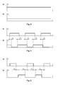
- Fig. 3 shows signals shown in Fig. 3 , where graph (a) corresponds to signal F 1 from strain gage 7 of insole 1, while graph (b) corresponds to signal F 2 from strain gage 7 of the other insole 1.
- signals F 1 and F 2 from strain gages 7 of both insoles 1 are essentially equal in value and feature almost complete overlap in time.
- Fig. 3 gives an example in which signal F 1 from strain gage 7 of insole 1 (graph (a)) is greater in value than signal F 2 from strain gage 7 of the other insole 1 (graph (b)). It means that the person is standing leaning on one leg more than the other.
- Such type of motor activity as walking is characterized by signals shown in Fig. 4 , where graph (a) corresponds to signal F 1 from strain gage 7 of insole 1, while graph (b) corresponds to signal F 2 from strain gage 7 of the other insole 1.
- This type of motor activity is characterized by alternating variation of signal values F 1 and F 2 from strain gages 7 of both insoles 1, and by the availability of partial overlap in time (overlap time interval T L ).
- Such type of motor activity as running is characterized by signals shown in Fig. 5 , where graph (a) corresponds to signal F 1 from strain gage 7 of insole 1, while graph (b) corresponds to signal F 2 from strain gage 7 of the other insole 1.
- This type of motor activity is characterized by alternating variation of signal values F 1 and F 2 from strain gages 7 of both insoles 1, and by the absence of time overlap of said signals. Conversely, a time gap between these signals designated as time interval T D is observed.
- the table below matches load sensor signal values and their temporal relationship to a certain type of motor activity (with at least two sensors placed in one insole).
- Load sensor signal values from both insoles and their temporal relationship Type of human motor activity Not available Sitting, lying, with shoes removed Essentially invariable values and almost complete time overlap Standing Partial overlap at cyclic repetition Walking No overlap at cyclic repetition Running Cyclic and essentially simultaneous change of sensor signal values from both insoles Jumping
- Similar signals from load sensors 2, 3, and 4 used to determine (identify) the type of person's motor activity can be also used to measure person's weight, including additionally carried weight.
- additional carried weight means extra weight borne by the person, for example carried items or special training weights.
- the weight measurement is basically reduced to the summation of signal values from all load sensors 2-4 of both insoles.
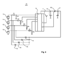
- FIG. 6 Another embodiment of device 12 for implementing the method using piezoelectric transducers as load sensors is shown in Fig. 6 .
- right and left insoles 1 (see Fig. 1 ) comprise a first load sensor 2 located near the heel, a second load sensor 3 located near the toe, and two additional sensors 4 located essentially along trajectory 5 of support reaction force at walking.
- Load sensors 2, 3, and 4 in this embodiment are represented by piezoelectric transducers 13, 14, and 15, respectively, connected via matching resistors R1-R8 to input/output ports L1-L4 of microcontroller 9.
- antenna output G of microcontroller 9 is connected to antenna 11.
- the method for measuring person's weight in accordance with the present invention using piezoelectric transducers as load sensors is implemented as follows.
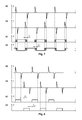
- Fig. 7 shows exemplary timing diagrams, which illustrate the temporal relationship of load sensor signals (e.g., piezoelectric transducers 13) from both insoles at walking, whereas Fig. 8 shows the same at running.
- load sensor signals e.g., piezoelectric transducers 13
- Fig. 8 shows the same at running.
- signals from the piezoelectric transducers given their inherent amplitude-frequency response, have the form of distinctive spikes corresponding to the moment when the foot pressure is applied to piezoelectric transducer and removed from said transducer (a signal of reverse polarity).
- the availability of spikes with opposing polarities makes it possible to reconstruct the signal corresponding to the duration of support phase, and, similarly to the preceding example, to determine temporary relationships of signals from piezoelectric transducers of both insoles.
- Fig. 7 Such type of motor activity as walking is characterized by signals shown in Fig. 7 , where graph (a) corresponds to signal F 1 from piezoelectric transducer 13 (also known as sensor 2) of one insole 1, and graph (b) corresponds to signal F 2 from piezoelectric transducer 13 (also known as sensor 2) of the other insole 1.
- Graphs (c) and (d) in Fig. 7 show signals P 1 and P 2 corresponding to the duration of foot pressure on piezoelectric transducers 13 of one and the other insole 1, respectively.
- the rising edge of signals P 1 and P 2 in graphs (c) and (d) of Fig. 7 corresponds to signals F 1 and F 2 with positive polarity in graphs (a) and (b) of Fig.
- Such type of motion activity as walking is characterized by alternating variation of signal values shown in graphs (c) and (d), and by the presence of their partial overlap (overlap time interval T L ).
- Fig. 8 such type of motor activity as running is characterized by signals shown in Fig. 8 , where graph (a) corresponds to signal F 1 from piezoelectric transducer 13 (also known as sensor 2) of one insole 1, and graph (b) corresponds to signal F 2 from piezoelectric transducer 13 (also known as sensor 2) of the other insole 1.
- Graphs (c) and (d) in Fig. 8 show signals P 1 and P 2 corresponding to the duration of foot pressure on piezoelectric transducers 13 of one and the other insole 1, respectively.
- the rising edge of signals P 1 and P 2 in graphs (c) and (d) of Fig. 8 corresponds to signals F 1 and F 2 with positive polarity in graphs (a) and (b) of Fig.
- Devices 6 ( Fig. 2 ) and 12 ( Fig. 6 ), as well as portions thereof, can be mounted in insole 1 alongside with corresponding load sensors.
- the devices are energized by battery 10 which can be represented by a rechargeable battery.
- the device can comprise a circuit for battery recharging performed in the process of walking or running, as shown in the example of device 12 (see Fig.6 ).
- Such a recharging circuit includes diodes 16, one for each piezoelectric transducer 13-15, storage capacitor 17, and thyristor 18 whose control input is coupled to input/output port L9 of microcontroller 9.
- One end of each diode 16 is connected to corresponding piezoelectric transducer 13-15, while all other ends are joined and connected to capacitor 17.
- microcontroller 9 switches off the registration mode of signals generated by foot pressure exerted on piezoelectric transducers, and sends said signals through diodes 16 to storage capacitor 17. In this mode, microcontroller 9 opens thyristor 18, thereby connecting charged capacitor 17 to battery 10. So, when a person is walking or running in shoes with device 12 and piezoelectric transducers 13-15 mounted in shoe insoles, battery 10 is recharged.
- the method in accordance with the present invention enables a real-time measurement of human weight, with type of motor activity and additionally carried weight taken into account.
- the data registered by load sensors mounted in insoles may also be used to detect the defects of person's musculoskeletal system, flat footedness, as well as to determine the slope of travel surface and its hardness, degree of comfort of the footwear worn, identification of gait specific for a person, etc.
- the method also enables a continuous monitoring of traveling pace, motion speed and acceleration, covered distance and duration of travel.
Landscapes
- Health & Medical Sciences (AREA)
- Life Sciences & Earth Sciences (AREA)
- Physics & Mathematics (AREA)
- Engineering & Computer Science (AREA)
- Medical Informatics (AREA)
- Animal Behavior & Ethology (AREA)
- Pathology (AREA)
- Oral & Maxillofacial Surgery (AREA)
- Biomedical Technology (AREA)
- Heart & Thoracic Surgery (AREA)
- Dentistry (AREA)
- Molecular Biology (AREA)
- Surgery (AREA)
- Biophysics (AREA)
- General Health & Medical Sciences (AREA)
- Public Health (AREA)
- Veterinary Medicine (AREA)
- General Physics & Mathematics (AREA)
- Physiology (AREA)
- Microelectronics & Electronic Packaging (AREA)
- Footwear And Its Accessory, Manufacturing Method And Apparatuses (AREA)
- Measurement Of The Respiration, Hearing Ability, Form, And Blood Characteristics Of Living Organisms (AREA)
- Force Measurement Appropriate To Specific Purposes (AREA)
Abstract
Description
- The invention relates to the field of measurements of bodily parameters in motion for diagnostic purposes, in particular to measuring human weight, including additionally carried weight, using load sensors located in shoe insoles.
- Various methods are known for determining the weight of a human in motion, which are implemented using pressure sensors disposed in shoes.
- Application
JP 2002090216 (publication date Sep. 11, 2000 - International patent application
WO 200136051 (publication date May, 05, 2001 -
US Patent 6273863 (publication date Aug. 14, 2001 ; A61B05/103, A61B05/117) describes a monitoring system for rehabilitating orthopedic patients with fractures of the lower extremities. The system includes a flexible insole worn inside the shoe. The insole includes pressure and/or force sensor connected to a CPU to measure the weight applied to injured leg. The system incorporates the principle of biofeedback to encourage the patient to load the limb with the optimal target weight recommended for the period of rehabilitation. - The closest to the claimed invention is the method and device for measuring weight of a human, as described in international patent application
WO2009059134 (publication date May 05, 2009 ; A61B05/103, G01L01/00). That concept makes it possible to monitor the weight applied by a patient to a non-healthy leg in order to prevent the exceedance of a preset threshold of limb load for a given patient. For this purpose, electrical or mechanical pressure sensors are mounted on the support surface. The sensors are located near the heel and toe of the foot, as well as across the entire surface of the foot sole. The support surface can be placed in shoes. Sensor signals are processed by a microcontroller which determines whether the weight applied to a non-healthy leg exceeds a preset threshold. - Known solutions for measuring the weight of a human are primarily intended for medical purposes, in particular, for measuring the weight applied by a patient to his/her non-healthy leg. This predetermines the complex design of the devices used therefor and restricts their application primarily to medical purposes.
- The technical problem solved by the present invention is to develop a method for determining weight of a human, especially the weight of a healthy human. A real-time determination of not only a human's own weight, but also of the weight additionally carried by the human, is enabled for different types of motor activities. The inventive method makes it possible to assess various physiological parameters of a human condition, including those related to the motor activity.
- One of the objects of this invention is a method for determining the weight of a human using signals generated by load sensors disposed in shoe insoles, with each insole having two load sensors, a first load sensor disposed in the heel region, and the second load sensor disposed in the toe region of the foot. The specific type of motor activity is determined based on the signals and their values from the load sensors from both insoles. The weight of a human, including additionally carried weight, is determined by summing up the load sensor signals and based on the type of the human's motor activity.
- During a motor activity, a human steps on the legs alternatingly, first on one, then the other leg. The load sensors located in the heel region and in the toe region make it possible to determine the duration of the contact of the foot with a base (support phase) and the duration of leg transfer (transfer phase) within one walking or running cycle. Since different types of motor activity are characterized by different correspondence in time between the support time and the transfer time, the correlation between the signals of the load sensors from different insoles lets one determine a pattern or a type of a motor activity.
- Specifically, the present method provides for determining the weight of a human, including additionally carried weight, directly during the motor activity (walking, running, etc.) and in accordance with the type of the motor activity. That approach provides for the assessment of various physiological parameters of a human condition, including those related to a motor activity.
- In particular implementations of this method, various types of a motor activity can be determined as follows.
- Such type of a motor activity as "walking" is identified if the signals from the load sensors in both insoles exhibit periodic variations of the values of the signals and the signals from the load sensors of different insoles partially overlap in time.
- The type of the motor activity is determined as "running" if the signals from the load sensors in both insoles exhibit periodic variations of the values of the signals and the signals from the load sensors of different insoles do not overlap in time.
- The type of the motor activity is determined as "standing" if the signals from the load sensors in both insoles exceed a predetermined value and the signals from different insoles overlap in time.
- The inventors have obtained a series of experimental dependencies that provide for the determination of the weight of a human, including additionally carried weight, in consideration with the specific type of a motor activity.
- For example, weight P, including additionally carried weight, of a person/human, who is walking at a slow pace of up to 60 steps per minute can be expressed as follows:

- where: KW is a calibration factor determined at walking for a person with a known weight;
- F is the mean value of a foot pressure force over one walking cycle, wherein:

- where: F 1max is the maximum value of summarized foot pressure forces registered by all load sensors in one insole;
- F 2max is the maximum value of summarized foot pressure forces registered by all load sensors in the other insole,
- wherein one cycle consists of two consecutive steps made by one foot and then the other.
- Weight P, including additionally carried weight, of a person, who is walking at a pace of 60 or more steps per minute can be expressed as follows:

- where: KW is a calibration factor determined at walking with pace of up to 60 steps per minute for a given person with a known weight;
- F is the mean value of a foot pressure force over one walking cycle, wherein:

- where: F 1max is the maximum value of summarized foot pressure forces registered by all load sensors in one insole;
- F 2max is the maximum value of summarized foot pressure forces registered by all the load sensors in the other insole;
- V is the number of steps per minute,
- wherein one cycle consists of two consecutive steps made by one foot and then the other.
- The weight, including additionally carried weight, of a person during running can be expressed by formula:

- where: KR is a calibration factor determined at running for a given person with a known weight;
- F is the mean value of a foot pressure force over one running cycle, wherein:

- where: F 1max is the maximum value of summarized foot pressure forces registered by all load sensors in one insole;
- F 2max is the maximum value of summarized foot pressure forces registered by all load sensors in the other insole;
- V is the number of steps per minute,
- wherein one running cycle is assumed to consist of two consecutive steps made by one foot and the other.
- The weight, including additionally carried weight, of a person during standing can be expressed as:

- where: KS is a calibration factor determined during standing for a given person with a known weight;
- F is the mean value of a foot pressure force over the period of standing, wherein:

- where: F 1max is the maximum value of summarized foot pressure forces registered by all load sensors in one insole;
- F 2max is the maximum value of summarized foot pressure forces registered by all load sensors in the other insole.
- Specifically, the method also contemplates providing additional load sensors in each insole, the additional sensors being disposed along a trajectory of a support reaction force at walking between the first load sensor and the second load sensor, detecting signals from the additional load sensors and using such signals in addition to using the signals from the first and the second load sensors.
- Another object of the invention is to provide an insole for determining the weight of the human according to the inventive method, the insole comprising a first load sensor disposed in the insole in a heel region, and a second load sensor disposed in the insole in a toe region, the first and the second load sensors being capable of generating signals detecting a pressure force applied by the person's foot.
- Additionally, the insole further comprises an analog-to-digital converter and a transceiver to convert the signals from the load sensors to a digital form and transmit them to an external processing unit.
- The invention is illustrated by the following graphic materials.
-
Fig. 1 is a schematic illustration of the design of the insole with load sensors mounted therein: shown here are both, left and right insoles and location of load sensors relative to the trajectory of support reaction force at walking; -
Fig. 2 shows a wiring diagram of an exemplary device for measuring the force applied by foot upon load sensors mounted in insoles, as shown inFig. 1 : each load sensor is realized as a strain transducer with four bridge-connected strain gages; -
Fig. 3 shows exemplary timing diagrams which illustrate the temporal relationship of load sensor signals from both insoles as registered by the circuit fromFig. 2 in case of standing activity. -
Fig. 4 shows exemplary timing diagrams which illustrate the temporal relationship of load sensor signals from both insoles as registered by the circuit fromFig. 2 in case of walking activity. -
Fig. 5 shows exemplary timing diagrams which illustrate the temporal relationship of load sensor signals from both insoles as registered by the circuit fromFig. 2 in case of running activity. -
Fig. 6 shows a circuit diagram of another exemplary device for measuring the force applied by foot upon load sensors placed in insole, as shown inFig. 1 : each load sensor is realized as a piezoelectric transducer. -
Fig. 7 shows exemplary timing diagrams which illustrate the temporal relationship of load sensor signals from both insoles as registered by the circuit fromFig. 6 in case of walking activity. -
Fig. 8 shows exemplary timing diagrams which illustrate the temporal relationship of load sensor signals from both insoles as registered by the circuit fromFig. 6 in case of running activity. - The present invention is illustrated by the following embodiments of insoles with load sensors realized as strain gages and piezoelectric transducers.
- In the first embodiment, each insole 1 (see.
Fig. 1 ) includes afirst load sensor 2 located near the heel of the foot, asecond load sensor 3 located near the toe of the foot, and twoadditional load sensors 4 located actually along thetrajectory 5 of support reaction forces at walking.Fig. 2 shows an exemplary schematic diagram ofdevice 6 for registering the force applied upon load sensor by foot. In this embodiment, load sensors 2-4 are represented by strain transducers (strain sensors) 7 each consisting of four bridge-connectedstrain gages 8. One bridge diagonal is connected topower supply 10, while the other is connected to input/output ports ofmicrocontroller 9 in a way that all four strain transducers 7 (first load sensor 2,second load sensor 3, and two additional load sensors 4) are eventually connected to eight input/output ports L1-L8 ofmicrocontroller 9 which registers analog signals fromstrain transducers 7 and converts them to digital form. Antenna output G ofmicrocontroller 9 equipped with a built-in transceiver is connected toantenna 11.Device 6 is energized bypower supply 10.Microcontroller 9 is switched into operating mode by commands from an external computer (not shown in the drawings). The external computer is mounted in a man-portable device and is also capable of determining exercise stress. - The method of human exercise stress monitoring according to the present invention is executed as follows.
- The type of motor activity is determined using signals from strain gages 7 (load sensors 2-4) of both
insoles 1,which are registered bysignal processing unit 6, and time relationship of said signals from right and leftinsoles 1. - For example, such activity as standing is distinguished by signals shown in
Fig. 3 , where graph (a) corresponds to signal F 1 fromstrain gage 7 ofinsole 1, while graph (b) corresponds to signal F 2 fromstrain gage 7 of theother insole 1. At this type of motor activity, signals F 1 and F 2 fromstrain gages 7 of bothinsoles 1 are essentially equal in value and feature almost complete overlap in time.Fig. 3 gives an example in which signal F 1 fromstrain gage 7 of insole 1 (graph (a)) is greater in value than signal F 2 fromstrain gage 7 of the other insole 1 (graph (b)). It means that the person is standing leaning on one leg more than the other. - Such type of motor activity as walking is characterized by signals shown in
Fig. 4 , where graph (a) corresponds to signal F 1 fromstrain gage 7 ofinsole 1, while graph (b) corresponds to signal F 2 fromstrain gage 7 of theother insole 1. This type of motor activity is characterized by alternating variation of signal values F 1 and F 2 fromstrain gages 7 of bothinsoles 1, and by the availability of partial overlap in time (overlap time interval TL ). - Such type of motor activity as running is characterized by signals shown in
Fig. 5 , where graph (a) corresponds to signal F 1 fromstrain gage 7 ofinsole 1, while graph (b) corresponds to signal F 2 fromstrain gage 7 of theother insole 1. This type of motor activity is characterized by alternating variation of signal values F 1 and F 2 fromstrain gages 7 of bothinsoles 1, and by the absence of time overlap of said signals. Conversely, a time gap between these signals designated as time interval TD is observed. - The availability of at least two load sensors in each insole, with the
first sensor 2 placed near the heel and thesecond sensor 3 near the toe, makes it possible to define not only the above-mentioned types of motor activity (walking, running, standing), but also other types like sitting, cycling, skiing. However, this method covers only those types of motor activity in which person's weight, including additionally carried weight, is transmitted to the feet. - The table below matches load sensor signal values and their temporal relationship to a certain type of motor activity (with at least two sensors placed in one insole).
Load sensor signal values from both insoles and their temporal relationship Type of human motor activity Not available Sitting, lying, with shoes removed Essentially invariable values and almost complete time overlap Standing Partial overlap at cyclic repetition Walking No overlap at cyclic repetition Running Cyclic and essentially simultaneous change of sensor signal values from both insoles Jumping - Similar signals from
load sensors - The mathematical relationships experimentally obtained by the inventors with due regard to the type of motor activity can be used for measuring person's weight, including additionally carried one.
- Thus, at standing activity the weight measurement is basically reduced to the summation of signal values from all load sensors 2-4 of both insoles.
- The weight, including additionally carried weight, of a standing person can be determined by formula:

- where: KS is a calibration factor to be determined for a given person with a known weight at standing;
- F is the mean value of pressure force of feet at standing. It can be determined for a certain period of time, e.g., from 5 to 10 seconds, wherein:

- where: F 1max is the maximum value of summarized foot pressure forces registered by all load sensors of one insole;
- F 2max is the maximum value of summarized foot pressure forces registered by all load sensors of the other insole;
- Calibration factor KS , like other calibration factors used for calculating person's weight at walking or running, can be determined in the process of system calibration. Yet, they can also be determined directly in the process of monitoring, when the person is known to carry no additional weight at a particular point of time, i.e., load sensors take up only person's known sole weight.
- At a slow walking pace of up to 60 steps per minute, person's weight P, including additionally carried weight, can be calculated using formula:

- where: KW is a calibration factor to be determined for a person with known weight at walking;
- F is the mean value of foot pressure force over one walking cycle, wherein:

- where: F 1max is the maximum value of summarized foot pressure forces registered by all load sensors of one insole;
- F 2max is the maximum value of summarized foot pressure forces registered by all load sensors of the other insole,
- whereat one cycle is assumed to consist of two consecutive steps made by one foot and the other.
- At walking pace of 60 or more steps per minute, person's weight, including additionally carried weight, can be calculated by formula:

- where: KW is a calibration factor to be determined for a given person with known weight, who is walking at pace of up to 60 steps per minute;
- F is the mean value of foot pressure force over one walking cycle, wherein:

- where: F 1max is the maximum value of summarized foot pressure forces registered by all load sensors of one insole;
- F 2max is the maximum value of summarized foot pressure forces registered by all load sensors of the other insole;
- V is the number of steps per minute,
- whereat one cycle is assumed to consist of two consecutive steps with one foot and the other;
- The weight, including additionally carried weight, of a person at running can be calculated by formula:

- where: KR is a calibration factor, which is determined for a given person with known weight at running;
- F is the mean value of foot pressure force over one running cycle, wherein:

- where: F 1max is the maximum value of summarized foot pressure forces registered by all load sensors of one insole;
- F 2max is the maximum value of summarized foot pressure forces registered by all load sensors of the other insole;
- V is the number of steps per minute at a given running pace,
- whereat one running cycle is assumed to consist of two consecutive steps made by one foot and the other.
- Another embodiment of
device 12 for implementing the method using piezoelectric transducers as load sensors is shown inFig. 6 . Similarly to the preceding embodiment, right and left insoles 1 (seeFig. 1 ) comprise afirst load sensor 2 located near the heel, asecond load sensor 3 located near the toe, and twoadditional sensors 4 located essentially alongtrajectory 5 of support reaction force at walking.Load sensors piezoelectric transducers microcontroller 9. Similarly to the embodiment shown inFig.2 , antenna output G ofmicrocontroller 9 is connected toantenna 11. - The method for measuring person's weight in accordance with the present invention using piezoelectric transducers as load sensors is implemented as follows.
- Similarly to the first implementation of the method, signals from
load sensors insole 1, represented here bypiezoelectric transducers Fig. 7 shows exemplary timing diagrams, which illustrate the temporal relationship of load sensor signals (e.g., piezoelectric transducers 13) from both insoles at walking, whereasFig. 8 shows the same at running. Contrary to embodiment with strain transducers 7 (seeFig. 4 and Fig. 5 ), signals from the piezoelectric transducers, given their inherent amplitude-frequency response, have the form of distinctive spikes corresponding to the moment when the foot pressure is applied to piezoelectric transducer and removed from said transducer (a signal of reverse polarity). The availability of spikes with opposing polarities makes it possible to reconstruct the signal corresponding to the duration of support phase, and, similarly to the preceding example, to determine temporary relationships of signals from piezoelectric transducers of both insoles. - Thus, such type of motor activity as walking is characterized by signals shown in
Fig. 7 , where graph (a) corresponds to signal F 1 from piezoelectric transducer 13 (also known as sensor 2) of oneinsole 1, and graph (b) corresponds to signal F 2 from piezoelectric transducer 13 (also known as sensor 2) of theother insole 1. Graphs (c) and (d) inFig. 7 show signals P 1 and P 2 corresponding to the duration of foot pressure onpiezoelectric transducers 13 of one and theother insole 1, respectively. The rising edge of signals P 1 and P 2 in graphs (c) and (d) ofFig. 7 corresponds to signals F 1 and F 2 with positive polarity in graphs (a) and (b) ofFig. 7 , respectively, while the falling edge of signals P 1 and P 2 in graphs (c) and (d) ofFig. 7 corresponds to signals F 1 and F 2 with negative polarity in graphs (a) and (b) ofFig. 7 , respectively. Such type of motion activity as walking is characterized by alternating variation of signal values shown in graphs (c) and (d), and by the presence of their partial overlap (overlap time interval TL ). - Similarly, such type of motor activity as running is characterized by signals shown in
Fig. 8 , where graph (a) corresponds to signal F 1 from piezoelectric transducer 13 (also known as sensor 2) of oneinsole 1, and graph (b) corresponds to signal F 2 from piezoelectric transducer 13 (also known as sensor 2) of theother insole 1. Graphs (c) and (d) inFig. 8 show signals P 1 and P 2 corresponding to the duration of foot pressure onpiezoelectric transducers 13 of one and theother insole 1, respectively. The rising edge of signals P 1 and P 2 in graphs (c) and (d) ofFig. 8 corresponds to signals F 1 and F 2 with positive polarity in graphs (a) and (b) ofFig. 8 , respectively, while the falling edge of signals P 1 and P 2 in graphs (c) and (d) ofFig. 8 corresponds to signals F 1 and F 2 with negative polarity in graphs (a) and (b) ofFig. 8 , respectively. Such type of motion activity as walking is characterized by alternating variation of signal values shown in graphs (c) and (d) with no overlap in time. Conversely, a time gap designated as time interval TD between these signals is observed. - To measure person's weight, including additionally carried weight, mathematical relations from the first embodiment of the present invention can be used. In this case, maximum values of signals F 1F 2 from piezoelectric transducers are used as the pressure force exerted by foot on load sensors located in insoles. In case of standing, person's weight is determined by values of signals F 1 and F 2 generated by piezoelectric transducers at the beginning of standing activity and upon its termination. Apart from that, the implementation of the method is similar to the one described in the preceding example.

- Devices 6 (
Fig. 2 ) and 12 (Fig. 6 ), as well as portions thereof, can be mounted ininsole 1 alongside with corresponding load sensors. The devices are energized bybattery 10 which can be represented by a rechargeable battery. Additionally, the device can comprise a circuit for battery recharging performed in the process of walking or running, as shown in the example of device 12 (seeFig.6 ). Such a recharging circuit includesdiodes 16, one for each piezoelectric transducer 13-15,storage capacitor 17, andthyristor 18 whose control input is coupled to input/output port L9 ofmicrocontroller 9. One end of eachdiode 16 is connected to corresponding piezoelectric transducer 13-15, while all other ends are joined and connected tocapacitor 17. In the process of recharging,microcontroller 9 switches off the registration mode of signals generated by foot pressure exerted on piezoelectric transducers, and sends said signals throughdiodes 16 tostorage capacitor 17. In this mode,microcontroller 9 opensthyristor 18, thereby connecting chargedcapacitor 17 tobattery 10. So, when a person is walking or running in shoes withdevice 12 and piezoelectric transducers 13-15 mounted in shoe insoles,battery 10 is recharged. - The method in accordance with the present invention enables a real-time measurement of human weight, with type of motor activity and additionally carried weight taken into account.
- Furthermore, the data registered by load sensors mounted in insoles, as described above, may also be used to detect the defects of person's musculoskeletal system, flat footedness, as well as to determine the slope of travel surface and its hardness, degree of comfort of the footwear worn, identification of gait specific for a person, etc. The method also enables a continuous monitoring of traveling pace, motion speed and acceleration, covered distance and duration of travel.
Claims (11)
- A method for determining weight of a human, the method comprising:registering signals from load sensors disposed in shoe insoles, wherein each insole comprises two load sensors, a first load sensor being disposed in a heel region and a second load sensor being disposed in a toe region;determining a type of motor activity by using the signals from the load sensors and by determining correspondence in time between the signals; anddetermining the weight of the human by summing values of the signals from the load sensors and based on the type of the motor activity, wherein determining the weight comprises determining additionally carried weight.
- The method of Claim 1, wherein the type of the motor activity is determined as "walking" if the signals from the load sensors in both insoles exhibit periodic variations of the values of the signals and the signals from the load sensors of different insoles partially overlap in time.
- The method of Claim 1, wherein the type of the motor activity is determined as "running" if the signals from the load sensors in both insoles exhibit periodic variations of the values of the signals and the signals from the load sensors of different insoles do not overlap in time.
- The method of Claim 1, wherein the type of the motor activity is determined as "standing" if the signals from the load sensors in both insoles exceed a predetermined value and the signals from different insoles overlap in time.
- The method of Claim 1, wherein the weight of the person, and the additionally carried weight, walking at a pace of up to 60 steps per minute is determined as:
 wherein: KW is a calibration factor determined for a person with a known weight at walking;F is a mean value of a foot pressure force over one walking cycle, wherein:
 where: F 1max is a maximum value of summarized foot pressure forces registered by all the load sensors in one insole; andF 2max is a maximum value of summarized foot pressure forces registered by all the load sensors of the other insole;wherein one walking cycle consists of two consecutive steps made by one foot and then another.
 - The method of Claim 1, wherein the weight of the person, and the additionally carried weight, walking at a pace of 60 or more steps per minute is determined as:
 wherein: KW is a calibration factor for a given person with a known weight walking at a pace of up to 60 steps per minute;F is a mean value of foot pressure force over one walking cycle, wherein:
 where: F 1max is a maximum value of summarized foot pressure forces registered by all the load sensors of one insole;F 2max is the maximum value of summarized foot pressure forces registered by all the load sensors of the other insole; andV is a number of steps per minute;wherein one walking cycle consists of two consecutive steps made by one foot and then another.
 - The method of Claim 1, wherein the weight of the person, and the additionally carried weight, during running is determined as:
 wherein: KR is a calibration factor determined for a given person with a known weight at running;F is a mean value of a foot pressure force over one running cycle, wherein:
 wherein: F 1max is a maximum value of summarized foot pressure forces registered by all the load sensors of one insole;F 2max is maximum value of summarized foot pressure forces registered by all the load sensors of the other insole; andV a number of steps per minute;wherein one running cycle consists of two consecutive steps made by one foot and then another.
 - The method of Claim 1, wherein the weight of the person, and the additionally carried weight, while standing is determined as:
 wherein: KS is a calibration factor determined for a given person with a known weight at standing;F is a mean value of a foot pressure force at standing, wherein:
 wherein: F 1max is a maximum value of summarized foot pressure forces registered by all the load sensors of one insole; andF 2max is the maximum value of summarized foot pressure forces registered by all the load sensors of the other insole.
 - The method of Claim 1, further comprising providing additional load sensors in each insole, the additional sensors being disposed along a trajectory of a support reaction force at walking between the first load sensor and the second load sensor, detecting signals from the additional load sensors and using such signals in addition to using the signals from the first and the second load sensors.
- An insole for determining the weight of the human according toClaim 1, comprising a first load sensor disposed in the insole in a heel region, and a second load sensor disposed in the insole in a toe region, the first and the second load sensors being capable of generating signals detecting a pressure force applied by the person's foot.
- The insole of Claim 10 further comprising an analog-to-digital converter and a transceiver to convert the signals from the load sensors to a digital form and transmit them to an external processing unit.
Applications Claiming Priority (2)
| Application Number | Priority Date | Filing Date | Title |
|---|---|---|---|
| RU2013110574/14A RU2531697C1 (en) | 2013-03-05 | 2013-03-05 | Method for determining individual's weight and inner sole for implementing it |
| PCT/RU2014/000138 WO2014137245A1 (en) | 2013-03-05 | 2014-03-04 | Method for determining an individual's weight and insole for the implementation thereof |
Publications (2)
| Publication Number | Publication Date |
|---|---|
| EP2966422A1 true EP2966422A1 (en) | 2016-01-13 |
| EP2966422A4 EP2966422A4 (en) | 2017-01-04 |
Family
ID=51491664
Family Applications (1)
| Application Number | Title | Priority Date | Filing Date |
|---|---|---|---|
| EP14759872.6A Withdrawn EP2966422A4 (en) | 2013-03-05 | 2014-03-04 | Method for determining an individual's weight and insole for the implementation thereof |
Country Status (8)
| Country | Link |
|---|---|
| US (1) | US20150359460A1 (en) |
| EP (1) | EP2966422A4 (en) |
| JP (1) | JP2016508818A (en) |
| KR (1) | KR20150122235A (en) |
| CN (1) | CN105229433A (en) |
| HK (1) | HK1220002A1 (en) |
| RU (1) | RU2531697C1 (en) |
| WO (1) | WO2014137245A1 (en) |
Cited By (22)
| Publication number | Priority date | Publication date | Assignee | Title |
|---|---|---|---|---|
| JP2016508818A (en) * | 2013-03-05 | 2016-03-24 | ヒールビー コーポレイション | Method for determining personal weight and insole for implementing the same |
| EP3653260A1 (en) | 2018-11-13 | 2020-05-20 | GTX medical B.V. | Sensor in clothing of limbs or footwear |
| EP3653259A1 (en) | 2018-11-13 | 2020-05-20 | GTX medical B.V. | Movement reconstruction control system |
| IT202000019315A1 (en) * | 2020-08-05 | 2022-02-05 | Univ Bologna Alma Mater Studiorum | SYSTEM AND METHOD FOR ASSESSING THE BIOMECHANICAL RISK FROM MANUAL HANDLING OF LOADS |
| US11672982B2 (en) | 2018-11-13 | 2023-06-13 | Onward Medical N.V. | Control system for movement reconstruction and/or restoration for a patient |
| US11691015B2 (en) | 2017-06-30 | 2023-07-04 | Onward Medical N.V. | System for neuromodulation |
| US11752342B2 (en) | 2019-02-12 | 2023-09-12 | Onward Medical N.V. | System for neuromodulation |
| US11839766B2 (en) | 2019-11-27 | 2023-12-12 | Onward Medical N.V. | Neuromodulation system |
| US11957910B2 (en) | 2011-01-03 | 2024-04-16 | California Institute Of Technology | High density epidural stimulation for facilitation of locomotion, posture, voluntary movement, and recovery of autonomic, sexual, vasomotor, and cognitive function after neurological injury |
| US11992684B2 (en) | 2017-12-05 | 2024-05-28 | Ecole Polytechnique Federale De Lausanne (Epfl) | System for planning and/or providing neuromodulation |
| US12023492B2 (en) | 2011-11-11 | 2024-07-02 | The Regents Of The University Of California | Non invasive neuromodulation device for enabling recovery of motor, sensory, autonomic, sexual, vasomotor and cognitive function |
| US12076301B2 (en) | 2013-09-27 | 2024-09-03 | The Regents Of The University Of California | Engaging the cervical spinal cord circuitry to re-enable volitional control of hand function in tetraplegic subjects |
| US12268878B2 (en) | 2017-02-17 | 2025-04-08 | The University Of British Columbia | Apparatus and methods for maintaining physiological functions |
| US12311169B2 (en) | 2013-03-15 | 2025-05-27 | The Regents Of The University Of California | Multi-site transcutaneous electrical stimulation of the spinal cord for facilitation of locomotion |
| US12357828B2 (en) | 2017-12-05 | 2025-07-15 | Ecole Polytechnique Federale De Lausanne (Epfl) | System for planning and/or providing neuromodulation |
| US12415079B2 (en) | 2019-11-27 | 2025-09-16 | Onward Medical N.V. | Neuromodulation system |
| US12434068B2 (en) | 2017-05-23 | 2025-10-07 | The Regents Of The University Of California | Accessing spinal networks to address sexual dysfunction |
| US12478777B2 (en) | 2018-08-23 | 2025-11-25 | The Regents Of The University Of California | Non-invasive spinal cord stimulation for nerve root palsy, cauda equina syndrome, and restoration of upper extremity function |
| US12551714B2 (en) | 2015-11-04 | 2026-02-17 | The Regents Of The University Of California | Magnetic stimulation of the spinal cord to restore locomotor function and/or control of bladder and bowel |
| US12613624B2 (en) | 2019-11-19 | 2026-04-28 | Onward Medical N.V. | Planning and/or control system for a neuromodulation system |
| US12623080B2 (en) | 2023-06-21 | 2026-05-12 | Onward Medical N.V. | Neuromodulation system |
| US12623070B2 (en) | 2019-05-22 | 2026-05-12 | The Regents Of The University Of California | Transcutaneous electrical spinal cord neuromodulator and uses thereof |
Families Citing this family (13)
| Publication number | Priority date | Publication date | Assignee | Title |
|---|---|---|---|---|
| JP6503239B2 (en) * | 2015-06-22 | 2019-04-17 | 花王株式会社 | INFORMATION PROCESSING APPARATUS, METHOD OF CORRECTING MEASURED VALUES, AND PROGRAM |
| CN105588624A (en) * | 2015-12-14 | 2016-05-18 | 联想(北京)有限公司 | Information processing method and wearable device |
| JP2017167051A (en) * | 2016-03-17 | 2017-09-21 | 北川工業株式会社 | Measurement information output system and program |
| KR20170121642A (en) * | 2016-04-25 | 2017-11-02 | 엘지전자 주식회사 | Smart shoes type mobile terminal and operating method thereof |
| CN105901823A (en) * | 2016-04-28 | 2016-08-31 | 乐视控股(北京)有限公司 | Method and device for measuring weight and smart shoes |
| AT518546B1 (en) | 2016-09-27 | 2017-11-15 | Stapptronics Gmbh | Insole or shoe sole |
| KR101878254B1 (en) * | 2016-10-31 | 2018-07-13 | 부산외국어대학교 산학협력단 | Smart Shoes System And Method for Realizing The Same |
| RU2660312C1 (en) * | 2017-08-01 | 2018-07-05 | Федеральное государственное бюджетное учреждение "Центральный научно-исследовательский испытательный институт инженерных войск" Министерства обороны Российской Федерации | Method for determining efficiency of biomechanical anthropomorphic means (passive exoskeletons) |
| CN108665586A (en) * | 2018-04-08 | 2018-10-16 | 中山市微大网络科技有限公司 | A kind of unattended shop based on electronics on-ground weigher is gone out antitheft access control system and method |
| RU2723606C1 (en) * | 2019-04-01 | 2020-06-16 | Общество с ограниченной ответственностью "ЭкзоАтлант" | Method for evaluation of user unloading efficiency during cargo transportation and holding by means of exoskeleton |
| US20210068492A1 (en) * | 2019-09-09 | 2021-03-11 | Emmanuel Onyekachi | Footwear and Method |
| CN115606908A (en) * | 2022-09-26 | 2023-01-17 | 合肥工业大学 | Multi-dimensional force measurement insole |
| WO2026006501A1 (en) * | 2024-06-28 | 2026-01-02 | Position Imaging, Inc. | Electronic tags for weighing objects |
Family Cites Families (17)
| Publication number | Priority date | Publication date | Assignee | Title |
|---|---|---|---|---|
| JPH0614803A (en) * | 1991-12-16 | 1994-01-25 | Hidekazu Takahashi | Canvas shoes for collecting kinematic information |
| CA2199458C (en) * | 1997-03-07 | 2000-06-27 | Tien-Tsai Huang | Electronic step counting shoe |
| US6273863B1 (en) | 1999-10-26 | 2001-08-14 | Andante Medical Devices, Ltd. | Adaptive weight bearing monitoring system for rehabilitation of injuries to the lower extremities |
| AU1169301A (en) | 1999-11-12 | 2001-05-30 | Andante Medical Devices Ltd. | Motor learning enhancement system for optimal rehabilitation of neurological disorders and orthopedic limb injuries |
| JP2002090216A (en) | 2000-09-11 | 2002-03-27 | Ueda Avancer Corp | Weight load measuring apparatus |
| CA2520067C (en) * | 2003-04-03 | 2012-07-24 | University Of Virginia Patent Foundation | Method and system for the derivation of human gait characteristics and detecting falls passively from floor vibrations |
| FR2873281A1 (en) * | 2004-07-26 | 2006-01-27 | Roya Khosravi | Sports shoe, has measurement device to measure physical values, and computerized calculating device and digital display device to calculate and display information concerning values of physical activity, respectively |
| US20080167580A1 (en) * | 2005-04-05 | 2008-07-10 | Andante Medical Devices Ltd. | Rehabilitation System |
| US7878990B2 (en) * | 2006-02-24 | 2011-02-01 | Al-Obaidi Saud M | Gait training device and method |
| US9005140B2 (en) * | 2007-11-02 | 2015-04-14 | The Research Foundation For The State University Of New York | Weight monitoring apparatus, weight monitoring system, and related methods thereof |
| WO2010096691A2 (en) * | 2009-02-20 | 2010-08-26 | The Regents Of The University Of Colorado, A Body Corporate | Footwear-based body weight monitor and postural allocation, physical activity classification, and energy expenditure calculator |
| WO2011026257A1 (en) * | 2009-09-03 | 2011-03-10 | Yang Changming | System and method for analyzing gait by fabric sensors |
| RU103064U1 (en) * | 2010-06-15 | 2011-03-27 | Олександр Олександрович Степанов | SHOES WITH MEASURING WEIGHTS FOR SHOES |
| CN102175356A (en) * | 2011-02-22 | 2011-09-07 | 中国科学院合肥物质科学研究院 | Device and method for measuring gait touch information |
| EP2556795A1 (en) * | 2011-08-09 | 2013-02-13 | Nederlandse Organisatie voor toegepast -natuurwetenschappelijk onderzoek TNO | Method and system for feedback on running style |
| CA2882453C (en) * | 2012-08-27 | 2021-07-20 | Universite Du Quebec A Chicoutimi | Method to determine physical properties of the ground, foot-worn sensor therefore, and method to advise a user of a risk of falling based thereon |
| RU2531697C1 (en) * | 2013-03-05 | 2014-10-27 | Общество С Ограниченной Ответственностью "Хилби" | Method for determining individual's weight and inner sole for implementing it |
-
2013
- 2013-03-05 RU RU2013110574/14A patent/RU2531697C1/en active
-
2014
- 2014-03-04 HK HK16107859.7A patent/HK1220002A1/en unknown
- 2014-03-04 CN CN201480012483.5A patent/CN105229433A/en active Pending
- 2014-03-04 WO PCT/RU2014/000138 patent/WO2014137245A1/en not_active Ceased
- 2014-03-04 JP JP2015561306A patent/JP2016508818A/en active Pending
- 2014-03-04 KR KR1020157026954A patent/KR20150122235A/en not_active Ceased
- 2014-03-04 EP EP14759872.6A patent/EP2966422A4/en not_active Withdrawn
-
2015
- 2015-08-24 US US14/833,753 patent/US20150359460A1/en not_active Abandoned
Cited By (26)
| Publication number | Priority date | Publication date | Assignee | Title |
|---|---|---|---|---|
| US11957910B2 (en) | 2011-01-03 | 2024-04-16 | California Institute Of Technology | High density epidural stimulation for facilitation of locomotion, posture, voluntary movement, and recovery of autonomic, sexual, vasomotor, and cognitive function after neurological injury |
| US12226631B2 (en) | 2011-11-11 | 2025-02-18 | The Regents Of The University Of California | Non invasive neuromodulation device for enabling recovery of motor, sensory, autonomic, sexual, vasomotor and cognitive function |
| US12023492B2 (en) | 2011-11-11 | 2024-07-02 | The Regents Of The University Of California | Non invasive neuromodulation device for enabling recovery of motor, sensory, autonomic, sexual, vasomotor and cognitive function |
| JP2016508818A (en) * | 2013-03-05 | 2016-03-24 | ヒールビー コーポレイション | Method for determining personal weight and insole for implementing the same |
| US12311169B2 (en) | 2013-03-15 | 2025-05-27 | The Regents Of The University Of California | Multi-site transcutaneous electrical stimulation of the spinal cord for facilitation of locomotion |
| US12076301B2 (en) | 2013-09-27 | 2024-09-03 | The Regents Of The University Of California | Engaging the cervical spinal cord circuitry to re-enable volitional control of hand function in tetraplegic subjects |
| US12551714B2 (en) | 2015-11-04 | 2026-02-17 | The Regents Of The University Of California | Magnetic stimulation of the spinal cord to restore locomotor function and/or control of bladder and bowel |
| US12268878B2 (en) | 2017-02-17 | 2025-04-08 | The University Of British Columbia | Apparatus and methods for maintaining physiological functions |
| US12434068B2 (en) | 2017-05-23 | 2025-10-07 | The Regents Of The University Of California | Accessing spinal networks to address sexual dysfunction |
| US11691015B2 (en) | 2017-06-30 | 2023-07-04 | Onward Medical N.V. | System for neuromodulation |
| US12357828B2 (en) | 2017-12-05 | 2025-07-15 | Ecole Polytechnique Federale De Lausanne (Epfl) | System for planning and/or providing neuromodulation |
| US11992684B2 (en) | 2017-12-05 | 2024-05-28 | Ecole Polytechnique Federale De Lausanne (Epfl) | System for planning and/or providing neuromodulation |
| US12478777B2 (en) | 2018-08-23 | 2025-11-25 | The Regents Of The University Of California | Non-invasive spinal cord stimulation for nerve root palsy, cauda equina syndrome, and restoration of upper extremity function |
| EP3653259A1 (en) | 2018-11-13 | 2020-05-20 | GTX medical B.V. | Movement reconstruction control system |
| US11672983B2 (en) | 2018-11-13 | 2023-06-13 | Onward Medical N.V. | Sensor in clothing of limbs or footwear |
| US11672982B2 (en) | 2018-11-13 | 2023-06-13 | Onward Medical N.V. | Control system for movement reconstruction and/or restoration for a patient |
| US11580877B2 (en) | 2018-11-13 | 2023-02-14 | Onward Medical N.V. | Movement reconstruction control system |
| EP3653260A1 (en) | 2018-11-13 | 2020-05-20 | GTX medical B.V. | Sensor in clothing of limbs or footwear |
| US11752342B2 (en) | 2019-02-12 | 2023-09-12 | Onward Medical N.V. | System for neuromodulation |
| US12623070B2 (en) | 2019-05-22 | 2026-05-12 | The Regents Of The University Of California | Transcutaneous electrical spinal cord neuromodulator and uses thereof |
| US12613624B2 (en) | 2019-11-19 | 2026-04-28 | Onward Medical N.V. | Planning and/or control system for a neuromodulation system |
| US12415079B2 (en) | 2019-11-27 | 2025-09-16 | Onward Medical N.V. | Neuromodulation system |
| US11839766B2 (en) | 2019-11-27 | 2023-12-12 | Onward Medical N.V. | Neuromodulation system |
| WO2022029655A1 (en) * | 2020-08-05 | 2022-02-10 | Alma Mater Studiorum – Università Di Bologna | System and method for the assessment of the biomechanical risk from manual handling of loads |
| IT202000019315A1 (en) * | 2020-08-05 | 2022-02-05 | Univ Bologna Alma Mater Studiorum | SYSTEM AND METHOD FOR ASSESSING THE BIOMECHANICAL RISK FROM MANUAL HANDLING OF LOADS |
| US12623080B2 (en) | 2023-06-21 | 2026-05-12 | Onward Medical N.V. | Neuromodulation system |
Also Published As
| Publication number | Publication date |
|---|---|
| EP2966422A4 (en) | 2017-01-04 |
| RU2531697C1 (en) | 2014-10-27 |
| CN105229433A (en) | 2016-01-06 |
| KR20150122235A (en) | 2015-10-30 |
| RU2013110574A (en) | 2014-09-10 |
| JP2016508818A (en) | 2016-03-24 |
| HK1220002A1 (en) | 2017-04-21 |
| WO2014137245A1 (en) | 2014-09-12 |
| US20150359460A1 (en) | 2015-12-17 |
Similar Documents
| Publication | Publication Date | Title |
|---|---|---|
| US20150359460A1 (en) | Method for determining an individual's weight and insole for the implementation thereof | |
| US10070682B2 (en) | Method for monitoring an individual's motor load and insole for the implementation thereof | |
| Saremi et al. | Reliability and validity of bilateral thigh and foot accelerometry measures of walking in healthy and hemiparetic subjects | |
| Zhang et al. | Estimating CoP trajectories and kinematic gait parameters in walking and running using instrumented insoles | |
| Maffiuletti et al. | Concurrent validity and intrasession reliability of the IDEEA accelerometry system for the quantification of spatiotemporal gait parameters | |
| Fulk et al. | Using sensors to measure activity in people with stroke | |
| Lee et al. | Wearable accelerometer system for measuring the temporal parameters of gait | |
| US20080167580A1 (en) | Rehabilitation System | |
| Lee et al. | Portable activity monitoring system for temporal parameters of gait cycles | |
| JPWO2019035444A1 (en) | Sole pressure measuring device, information providing device and information providing method | |
| US20060273913A1 (en) | Device for measuring and monitoring the fractional load of orthopaedic and surgical patents | |
| WO2019004863A1 (en) | Method of assessing degree of rehabilitation using an active exoskeleton for patients with disorders of the musculoskeletal system | |
| US20250295359A1 (en) | Intervention based on detected gait kinematics | |
| Figueiredo et al. | Instrumented insole system for ambulatory and robotic walking assistance: First advances | |
| Revathi et al. | Development of IoT-enabled smart shoe for gait prediction and abnormality analysis | |
| AlGheshyan | Comparison of ground reaction force in treadmill walking and in overground walking | |
| Lee et al. | New computer protocol with subsensory stimulation and visual/auditory biofeedback for balance assessment in amputees | |
| Bakhteri et al. | Microprocessor-based athlete health monitoring device based on heart rate and stride length calculation | |
| Tselishchev et al. | The Development of Pedograph and Methods for Diagnosing Gait Disorders | |
| Tanioka et al. | Real-time measurement of frozen gait in patient with parkinsonism using a sensor-controlled walker | |
| Ishii et al. | Shoe-type device to estimate body balance focusing on the relationship between CoM and BoS estimated from CoP | |
| Kwon et al. | Age-and sex-related differences in muscle mechanics and gait biomechanics during incline walking | |
| Leatham | Tibial Acceleration and Shock Attenuation in Female and Male Distance Runners at Different Levels of Body Weight Unloading | |
| Hellstrom et al. | Carried Weight Affects Walking Speed Monitoring with the IngVaL System. | |
| Jatsun et al. | A Computer System for Biomechanical Studies of the Foot by Podography |
Legal Events
| Date | Code | Title | Description |
|---|---|---|---|
| PUAI | Public reference made under article 153(3) epc to a published international application that has entered the european phase |
Free format text: ORIGINAL CODE: 0009012 |
|
| 17P | Request for examination filed |
Effective date: 20150925 |
|
| AK | Designated contracting states |
Kind code of ref document: A1 Designated state(s): AL AT BE BG CH CY CZ DE DK EE ES FI FR GB GR HR HU IE IS IT LI LT LU LV MC MK MT NL NO PL PT RO RS SE SI SK SM TR |
|
| AX | Request for extension of the european patent |
Extension state: BA ME |
|
| DAX | Request for extension of the european patent (deleted) | ||
| A4 | Supplementary search report drawn up and despatched |
Effective date: 20161201 |
|
| RIC1 | Information provided on ipc code assigned before grant |
Ipc: A43B 17/00 20060101ALI20161125BHEP Ipc: G06F 19/00 20110101ALI20161125BHEP Ipc: G01G 3/13 20060101AFI20161125BHEP Ipc: A61B 5/22 20060101ALI20161125BHEP |
|
| STAA | Information on the status of an ep patent application or granted ep patent |
Free format text: STATUS: THE APPLICATION HAS BEEN WITHDRAWN |
|
| 18W | Application withdrawn |
Effective date: 20170322 |