EP2966366B1 - Heat pump water heating system - Google Patents
Heat pump water heating system Download PDFInfo
- Publication number
- EP2966366B1 EP2966366B1 EP15163942.4A EP15163942A EP2966366B1 EP 2966366 B1 EP2966366 B1 EP 2966366B1 EP 15163942 A EP15163942 A EP 15163942A EP 2966366 B1 EP2966366 B1 EP 2966366B1
- Authority
- EP
- European Patent Office
- Prior art keywords
- tank
- temperature
- water
- circulation
- pump
- Prior art date
- Legal status (The legal status is an assumption and is not a legal conclusion. Google has not performed a legal analysis and makes no representation as to the accuracy of the status listed.)
- Not-in-force
Links
Images

Classifications
-
- F—MECHANICAL ENGINEERING; LIGHTING; HEATING; WEAPONS; BLASTING
- F24—HEATING; RANGES; VENTILATING
- F24H—FLUID HEATERS, e.g. WATER OR AIR HEATERS, HAVING HEAT-GENERATING MEANS, e.g. HEAT PUMPS, IN GENERAL
- F24H4/00—Fluid heaters characterised by the use of heat pumps
- F24H4/02—Water heaters
- F24H4/04—Storage heaters
-
- F—MECHANICAL ENGINEERING; LIGHTING; HEATING; WEAPONS; BLASTING
- F24—HEATING; RANGES; VENTILATING
- F24D—DOMESTIC- OR SPACE-HEATING SYSTEMS, e.g. CENTRAL HEATING SYSTEMS; DOMESTIC HOT-WATER SUPPLY SYSTEMS; ELEMENTS OR COMPONENTS THEREFOR
- F24D17/00—Domestic hot-water supply systems
- F24D17/0026—Domestic hot-water supply systems with conventional heating means
- F24D17/0031—Domestic hot-water supply systems with conventional heating means with accumulation of the heated water
-
- F—MECHANICAL ENGINEERING; LIGHTING; HEATING; WEAPONS; BLASTING
- F24—HEATING; RANGES; VENTILATING
- F24D—DOMESTIC- OR SPACE-HEATING SYSTEMS, e.g. CENTRAL HEATING SYSTEMS; DOMESTIC HOT-WATER SUPPLY SYSTEMS; ELEMENTS OR COMPONENTS THEREFOR
- F24D17/00—Domestic hot-water supply systems
- F24D17/02—Domestic hot-water supply systems using heat pumps
-
- F—MECHANICAL ENGINEERING; LIGHTING; HEATING; WEAPONS; BLASTING
- F24—HEATING; RANGES; VENTILATING
- F24D—DOMESTIC- OR SPACE-HEATING SYSTEMS, e.g. CENTRAL HEATING SYSTEMS; DOMESTIC HOT-WATER SUPPLY SYSTEMS; ELEMENTS OR COMPONENTS THEREFOR
- F24D19/00—Details
- F24D19/0092—Devices for preventing or removing corrosion, slime or scale
-
- F—MECHANICAL ENGINEERING; LIGHTING; HEATING; WEAPONS; BLASTING
- F24—HEATING; RANGES; VENTILATING
- F24D—DOMESTIC- OR SPACE-HEATING SYSTEMS, e.g. CENTRAL HEATING SYSTEMS; DOMESTIC HOT-WATER SUPPLY SYSTEMS; ELEMENTS OR COMPONENTS THEREFOR
- F24D19/00—Details
- F24D19/10—Arrangement or mounting of control or safety devices
- F24D19/1006—Arrangement or mounting of control or safety devices for water heating systems
- F24D19/1051—Arrangement or mounting of control or safety devices for water heating systems for domestic hot water
- F24D19/1054—Arrangement or mounting of control or safety devices for water heating systems for domestic hot water the system uses a heat pump
-
- F—MECHANICAL ENGINEERING; LIGHTING; HEATING; WEAPONS; BLASTING
- F24—HEATING; RANGES; VENTILATING
- F24H—FLUID HEATERS, e.g. WATER OR AIR HEATERS, HAVING HEAT-GENERATING MEANS, e.g. HEAT PUMPS, IN GENERAL
- F24H15/00—Control of fluid heaters
- F24H15/20—Control of fluid heaters characterised by control inputs
- F24H15/212—Temperature of the water
- F24H15/223—Temperature of the water in the water storage tank
-
- F—MECHANICAL ENGINEERING; LIGHTING; HEATING; WEAPONS; BLASTING
- F24—HEATING; RANGES; VENTILATING
- F24H—FLUID HEATERS, e.g. WATER OR AIR HEATERS, HAVING HEAT-GENERATING MEANS, e.g. HEAT PUMPS, IN GENERAL
- F24H15/00—Control of fluid heaters
- F24H15/30—Control of fluid heaters characterised by control outputs; characterised by the components to be controlled
- F24H15/335—Control of pumps, e.g. on-off control
-
- F—MECHANICAL ENGINEERING; LIGHTING; HEATING; WEAPONS; BLASTING
- F24—HEATING; RANGES; VENTILATING
- F24H—FLUID HEATERS, e.g. WATER OR AIR HEATERS, HAVING HEAT-GENERATING MEANS, e.g. HEAT PUMPS, IN GENERAL
- F24H15/00—Control of fluid heaters
- F24H15/40—Control of fluid heaters characterised by the type of controllers
- F24H15/414—Control of fluid heaters characterised by the type of controllers using electronic processing, e.g. computer-based
-
- F—MECHANICAL ENGINEERING; LIGHTING; HEATING; WEAPONS; BLASTING
- F24—HEATING; RANGES; VENTILATING
- F24H—FLUID HEATERS, e.g. WATER OR AIR HEATERS, HAVING HEAT-GENERATING MEANS, e.g. HEAT PUMPS, IN GENERAL
- F24H9/00—Details
- F24H9/20—Arrangement or mounting of control or safety devices
- F24H9/2007—Arrangement or mounting of control or safety devices for water heaters
- F24H9/2014—Arrangement or mounting of control or safety devices for water heaters using electrical energy supply
- F24H9/2021—Storage heaters
-
- F—MECHANICAL ENGINEERING; LIGHTING; HEATING; WEAPONS; BLASTING
- F24—HEATING; RANGES; VENTILATING
- F24H—FLUID HEATERS, e.g. WATER OR AIR HEATERS, HAVING HEAT-GENERATING MEANS, e.g. HEAT PUMPS, IN GENERAL
- F24H15/00—Control of fluid heaters
- F24H15/20—Control of fluid heaters characterised by control inputs
- F24H15/288—Accumulation of deposits, e.g. lime or scale
-
- F—MECHANICAL ENGINEERING; LIGHTING; HEATING; WEAPONS; BLASTING
- F24—HEATING; RANGES; VENTILATING
- F24H—FLUID HEATERS, e.g. WATER OR AIR HEATERS, HAVING HEAT-GENERATING MEANS, e.g. HEAT PUMPS, IN GENERAL
- F24H15/00—Control of fluid heaters
- F24H15/40—Control of fluid heaters characterised by the type of controllers
- F24H15/486—Control of fluid heaters characterised by the type of controllers using timers
Definitions
- the present invention relates to a heat pump water heating system, and particularly, to scale deposition in a heat exchanger.
- a water heating system including a water-refrigerant heat exchanger that performs heat exchange between refrigerant and tank water by using a heat pump as a heat source, a hot water/cold water supply circuit that returns the tank water boiled by the heat exchange in the water-refrigerant heat exchanger to a tank and stores the tank water therein, and control means that performs a boiling operation by operating a pump provided in the hot water/cold water supply circuit, feeding the tank water to the water-refrigerant heat exchanger by the pump, and boiling the tank water by the heat exchange with the refrigerant in the water-refrigerant heat exchanger.
- Water such as tap water and ground water normally contains hardness components such as calcium and magnesium.
- a temperature of calcium or magnesium contained in tap water or the like is increased in a heating section for tank water of the water-refrigerant heat exchanger.
- the calcium or magnesium is transformed into calcium carbonate or the like (referred to as scale below), and precipitates on a surface or the like of the water-refrigerant heat exchanger.
- the scale causes problems that heat exchange efficiency of the water-refrigerant heat exchanger is reduced, and a flow path is closed.
- a water heating system described in Patent Literature 1 is a water heating system that directly exchanges heat between refrigerant and tap water, and especially in Europe, a water heating system is generally employed that circulates water heated by refrigerant and then exchanges heat between the circulated water and tap water (for example, see Patent Literature 2).
- US 4,527,618 A discloses a heat pump water heating system according to the preamble of claim 1 and shows a thermal energy storage and transfer system including solar energy collector means disposed to receive incident solar energy, thermal energy exchange means disposed in a utilization area, three water storage tanks, one of which is at least three times larger than the other two storage tanks. Water is selectively circulated through a first circulation loop between the solar collector and one small tank for transferring solar energy from the collector; through a second circulation loop between the second small tank and the utilization area; and through a third circulation loop between the large tank and the two smaller tanks. A heat pump is coupled between the two smaller storage tanks for transferring thermal energy between those two tanks.
- a highest hot water storage temperature of the water heating system which is determined by characteristics of the refrigerant, is about 60 degrees C.
- the precipitation of calcium and/or magnesium contained in tap water starts at around 55 degrees C, the precipitation of scale occurs at about the highest hot water storage temperature of 60 degrees C immediately before the water is boiled. Since temperatures of the refrigerant and the water become close to each other immediately before the water is boiled, heat exchange efficiency between the refrigerant and the water is reduced, and it takes a longer time until the temperature of the water is increased up to the highest hot water storage temperature. Accordingly, a problem occurs that a scale deposition amount increases in proportion to the time.
- the present invention has been made to overcome the above problems, and an object of the present invention is to obtain a heat pump water heating system which reduces scale deposition in a heat exchanger.
- a heat pump water heating system of the present invention includes the combination of the features of claim 1.
- the heat source for boiling the tank water is switched to the second heat source having a higher temperature than the heat pump unit thereby increasing the temperature of the tank water within the hot water storage tank in a shorter time. Accordingly, a scale deposition amount in a plate heat exchanger that performs heat exchange between refrigerant and tank water can be reduced.
- Fig. 1 is a schematic view illustrating a heat pump water heating system according to a first embodiment of the present invention.
- a heat pump water heating system 200 includes a heat pump heat source circulation circuit 101, a boiler heat source circulation circuit 102, a mixing tank circulation circuit 103, a tank circulation circuit 104, a temperature sensor 20, and a controller 30.
- a heat pump unit 1 In the heat pump heat source circulation circuit 101, a heat pump unit 1, a connection pipe 2, a mixing tank 3, a connection pipe 4, and a circulation pump 5 are connected in an annular shape.
- a highly energy-saving heat pump is used as the heat pump unit 1 that is a heat source of the heat pump heat source circulation circuit 101, and R410A is used as refrigerant.
- the circulation pump 5 circulates water within the heat pump heat source circulation circuit 101 in the order of the heat pump unit 1, the connection pipe 2, the mixing tank 3, the connection pipe 4, and the heat pump unit 1.
- a boiler 6, a connection pipe 7, the mixing tank 3, a connection pipe 8, and a circulation pump 9 are connected in an annular shape.
- a heat source such as a boiler and an electric heater that enables heating at a higher temperature than the heat pump is used as the boiler 6 that is a heat source of the boiler heat source circulation circuit 102.
- the circulation pump 9 circulates water within the boiler heat source circulation circuit 102 in the order of the boiler 6, the connection pipe 7, the mixing tank 3, the connection pipe 8, and the boiler 6.
- the mixing tank circulation circuit 103 In the mixing tank circulation circuit 103, the mixing tank 3, a connection pipe 10, a plate heat exchanger 11, a connection pipe 12, and a circulation pump 13 are connected in an annular shape.
- the circulation pump 13 circulates water within the mixing tank circulation circuit 103 in the order of the mixing tank 3, the connection pipe 10, the plate heat exchanger 11, the connection pipe 12, and the mixing tank 3.
- An upper portion of the mixing tank 3 is connected to the heat pump unit 1 by the connection pipe 2, and a lower portion of the mixing tank 3 is connected to the heat pump unit 1 by the connection pipe 4 via the circulation pump 5.
- the upper portion of the mixing tank 3 is connected to the boiler 6 by the connection pipe 7, and the lower portion of the mixing tank 3 is connected to the boiler 6 by the connection pipe 8 via the circulation pump 9.
- Water is fed between the heat pump heat source circulation circuit 101 or the boiler heat source circulation circuit 102 and the mixing tank circulation circuit 103 through the pipes.
- a hot water storage tank 14 In the tank circulation circuit 104, a hot water storage tank 14, a circulation pump 15, a connection pipe 16, the plate heat exchanger 11, and a connection pipe 17 are connected in an annular shape.
- the circulation pump 15 sucks water in a bottom portion within the tank, and feeds the water to an upper portion of the tank through the connection pipe 16, the plate heat exchanger 11, and the connection pipe 17.
- the hot water storage tank 14 is provided with a water supply pipe 18 that supplies tap water, and a hot water spout pipe 19 that spouts hot water.
- a water inlet of the water supply pipe 18 is provided in a lower portion within the hot water storage tank 14, and tap water is supplied to the lower portion within the hot water storage tank from the water supply pipe 18.
- a water outlet of the hot water spout pipe 19 is provided in an upper portion within the hot water storage tank 14, and hot water stored in the upper portion within the hot water storage tank 14 is spouted from the hot water spout pipe 19.
- the temperature sensor 20 is installed on the hot water storage tank 14, and detects a temperature of tank water within the hot water storage tank.
- the controller 30 is composed of, for example, a microcomputer.
- the controller 30 reads the temperature of the tank water within the hot water storage tank 14 from the temperature sensor 20, and controls start or stop of each circulation pump according to the temperature of the tank water.
- a heat source switch tank temperature for switching the water circulation circuit described below is set in the controller 30.
- the heat source switch tank temperature is set at 55 degrees C at which a precipitation amount of calcium and/or magnesium in tap water is increased.
- a tank preset temperature for stopping all the circulation pumps is also set in the controller 30.
- the tank preset temperature is set at about 60 degrees C, which is a boiling upper-limit temperature of the hot water storage tank 14, when the heat pump using R410A as the refrigerant is used as the heat source.
- the heat pump water heating system 200 is a system in which the circulation circuit and the heat source are switched according to the temperature of the tank water within the hot water storage tank 14. Therefore, the operation of the heat pump water heating system 200 is described below based on respective cases in which the tank water within the hot water storage tank 14 has different temperatures.
- the circulation pump 15 When a boiling operation of the hot water storage tank 14 is started, the circulation pump 15 is activated in the tank circulation circuit 104.
- the tank water having a low temperature in the bottom portion within the hot water storage tank 14 is fed to the upper portion of the hot water storage tank 14 sequentially through the connection pipe 16, the plate heat exchanger 11, and the connection pipe 17. The operation is performed regardless of the temperature of the tank water until the boiling operation of the hot water storage tank 14 is terminated.
- the circulation pump 5 in the heat pump heat source circulation circuit 101 is activated, and the highly energy-saving heat pump unit 1 is used as the heat source.
- the circulation pump 5 feeds high-temperature water heated by the heat pump unit 1 to the upper portion of the mixing tank 3 through the connection pipe 2.
- the high-temperature water flowing into the upper portion of the mixing tank 3 is fed from the upper portion of the mixing tank 3 to the lower portion of the mixing tank 3 sequentially through the connection pipe 10, the plate heat exchanger 11, and the connection pipe 12 by the circulation pump 13 to be circulated within the mixing tank circulation circuit 103.
- the high-temperature water exchanges heat with the low-temperature tank water sucked from the bottom portion of the hot water storage tank 14 by the circulation pump 15 when passing through the plate heat exchanger 11, so that the tank water has a high temperature, and returns to the hot water storage tank 14 through the connection pipe 17.
- the water whose temperature is decreased by exchanging heat with the low-temperature tank water in the plate heat exchanger 11 returns to the mixing tank 3, is sucked by the circulation pump 5 through the connection pipe 4, and is returned to the heat pump unit 1.
- the low-temperature water is boiled again by the heat pump unit 1 serving as the heat source.
- the heat source switch tank temperature e.g. 55 degrees C
- the controller 30 stops the circulation pump 5 and activates the circulation pump 9 in order to switch the heat source.
- a temperature of water is increased by the boiler 6 that enables heating at a higher temperature than the heat pump unit 1. Accordingly, the temperature of the water is increased in a shorter time than that of the case in which the temperature of the water is increased by the heat pump unit 1, thereby making short a time length in which the scale is generated.
- the circulation pump 9 feeds the high-temperature water heated by the boiler 6 to the upper portion of the mixing tank 3 through the connection pipe 7.
- the high-temperature water flowing into the upper portion of the mixing tank 3 is circulated within the mixing tank circulation circuit 103 similarly to the case described above, and the water and the tank water exchange heat in the plate heat exchanger 11.
- the tank water thereby has a high temperature and returns to the hot water storage tank 14 through the connection pipe 17.
- the water whose temperature is decreased by exchanging heat with the low-temperature tank water in the plate heat exchanger 11 returns to the mixing tank 3, is sucked by the circulation pump 9 through the connection pipe 8, and is returned to the boiler 6.
- the low-temperature water is boiled again by the boiler 6 as the heat source.
- the controller 30 stops the circulation pump 9, the circulation pump 13, and the circulation pump 15 in operation in order to terminate the boiling operation of the tank water.
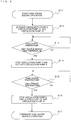
- Fig. 2 is a flowchart illustrating a control operation of the controller 30 of the heat pump water heating system 200 according to the first embodiment of the present invention. In the following, the control operation of the controller 30 is described based on respective steps in Fig. 2 with reference to Fig. 1 .
- the controller 30 activates the circulation pump 5 and the circulation pump 13, to circulate the water within the heat pump heat source circulation circuit 101 and the mixing tank circulation circuit 103. Moreover, the controller 30 activates the circulation pump 15, to circulate the water within the tank circulation circuit 104.
- the controller 30 reads the temperature of the tank water within the hot water storage tank 14 from the temperature sensor 20, and compares the temperature with the heat source switch tank temperature. If the temperature of the tank water is equal to or higher than the heat source switch tank temperature, the operation proceeds to step S14. Otherwise, the operation proceeds to step S13 again.
- the controller 30 In order to switch the heat source for increasing the temperature of the water from the heat pump unit 1 of the heat pump heat source circulation circuit 101 to the boiler 6 of the boiler heat source circulation circuit 102, the controller 30 stops the circulation pump 5 of the heat pump heat source circulation circuit 101, and activates the circulation pump 9 of the boiler heat source circulation circuit 102.
- the controller 30 reads the temperature of the tank water within the hot water storage tank 14 from the temperature sensor 20, and compares the temperature with the tank preset temperature. If the temperature of the tank water is equal to or higher than the tank preset temperature, the operation proceeds to step S16. Otherwise, the operation proceeds to step S15 again.
- the controller 30 stops the circulation pump 9 and the circulation pump 13, to stop the circulation of the water within the boiler heat source circulation circuit 102 and the mixing tank circulation circuit 103. Moreover, the controller 30 stops the circulation pump 15, to stop the circulation of the water within the tank circulation circuit 104.
- R410A is cited as an example of the refrigerant of the heat pump heat source circulation circuit 101 in the first embodiment, the present invention is not limited thereto.
- Refrigerant such as carbon dioxide, propane, and propylene may be also used.
- the plate heat exchanger 11 is cited as an example of the heat exchanger, the present invention is not limited thereto.
- a shell-and-tube heat exchanger, a double-tube heat exchanger or the like may be also used.
- the heat source switch tank temperature is set at 55 degrees C in the first embodiment, the heat source switch tank temperature may be changed, for example, within a range of "50 degrees C ⁇ the heat source switch tank temperature ⁇ the tank preset temperature" according to a condition under which the scale precipitates.
- the tank preset temperature when R410A is used as the refrigerant is set at 60 degrees C, the tank preset temperature may be changed, for example, within a range of "40 degrees C ⁇ the tank preset temperature ⁇ 90 degrees C" according to characteristics of the refrigerant. The same applies to a second example described below.
- the heat pump unit 1 corresponds to a "first heat source” in the present invention
- the boiler 6 corresponds to a “second heat source” in the present invention
- the circulation pump 5 corresponds to a "first circulation pump” in the present invention
- the circulation pump 9 a "second circulation pump” in the present invention
- the circulation pump 13 a "third circulation pump” in the present invention
- the circulation pump 15 a "fourth circulation pump” in the present invention.
- the heat pump heat source circulation circuit 101 corresponds to a "first circulation circuit” in the present invention
- the boiler heat source circulation circuit 102 a "second circulation circuit” in the present invention
- the mixing tank circulation circuit 103 a "third circulation circuit” in the present invention
- the tank circulation circuit 104 a "fourth circulation circuit” in the present invention.
- the heat source switch tank temperature corresponds to a "first preset temperature” in the present invention
- the tank preset temperature corresponds to a "second preset temperature”.
- the plate heat exchanger 11 corresponds to a "heat exchanger" in the present invention.
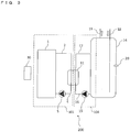
- Fig. 3 is a schematic view illustrating a heat pump water heating system 200 according to a second example. This example is not an embodiment of the present invention but helpful to understand certain aspects thereof.
- the heat pump water heating system 200 includes a heat pump heat source circulation circuit 101, a tank circulation circuit 104, a temperature sensor 20, and a controller 30.
- a heat pump unit 1 In the heat pump heat source circulation circuit 101, a heat pump unit 1, a connection pipe 2, a plate heat exchanger 11, a connection pipe 4, and a circulation pump 5 are connected in an annular shape.
- a highly energy-saving heat pump is used as a heat source of the heat pump heat source circulation circuit 101
- R410A is used as refrigerant.
- the circulation pump 5 circulates water within the heat pump heat source circulation circuit 101 in the order of the heat pump unit 1, the connection pipe 2, the plate heat exchanger 11, the connection pipe 4, and the heat pump unit 1.
- the tank circulation circuit 104 has the same configuration as that in the first embodiment described above.
- the temperature sensor 20 is installed on the hot water storage tank 14, and detects a temperature of water within the hot water storage tank 14.
- the controller 30 is composed of, for example, a microcomputer.
- the controller 30 reads the temperature of the tank water within the hot water storage tank 14 from the temperature sensor 20, and controls start or stop of each circulation pump according to the temperature of the tank water.
- a tank preset temperature for stopping the circulation pump 15 described below is set in the controller 30.
- the tank preset temperature is set at about 60 degrees C, which is a boiling upper-limit temperature of the hot water storage tank 14, when the heat pump using R410A as the refrigerant is used as the heat source.
- the controller 30 includes a timer (not shown). A time length until the plate heat exchanger 11 is cooled is previously set in the timer.
- the circulation pump 15 When a boiling operation of the hot water storage tank 14 is started, the circulation pump 15 is activated. The tank water having a low temperature within the hot water storage tank 14 is fed to the upper portion of the hot water storage tank 14 from the bottom portion of the hot water storage tank 14 sequentially through the connection pipe 16, the plate heat exchanger 11, and the connection pipe 17.
- the highly energy-saving heat pump unit 1 in the heat pump heat source circulation circuit 101 increases a temperature of water as the heat source.
- the circulation pump 5 feeds the high-temperature water heated by the heat pump unit 1 to the plate heat exchanger 11 through the connection pipe 2.
- the high-temperature water flowing into the plate heat exchanger 11 exchanges heat with the low-temperature tank water in the plate heat exchanger 11.
- the tank water thereby has a high temperature, and returns to the hot water storage tank 14 through the connection pipe 17.
- the water whose temperature is decreased by exchanging heat with the low-temperature tank water in the plate heat exchanger 11 is sucked by the circulation pump 5, passes through the connection pipe 4, and is returned to the heat pump unit 1.
- the low-temperature water is boiled again by the heat pump unit 1 as the heat source.
- the heat pump water heating system 200 repeats the above operation.
- the controller 30 stops the circulation pump 15.
- the controller 30 further measures the previously-set time length until the plate heat exchanger 11 is cooled (referred to as a reference time below) by using the timer, and stops the circulation pump 5 after the elapse of the reference time (for example, 10 minutes).
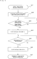
- Fig. 4 is a flowchart illustrating a control operation of the controller 30 of the heat pump water heating system 200 according to the second example. In the following, the control operation of the controller 30 is described based on respective steps in Fig. 4 with reference to Fig. 3 .
- the controller 30 activates the circulation pump 5 and the circulation pump 15, to circulate the water within the heat pump heat source circulation circuit 101 and the water within the tank circulation circuit 104.
- the controller 30 reads the temperature of the tank water within the hot water storage tank 14 from the temperature sensor 20, and compares the temperature with the tank preset temperature. If the temperature of the tank water is equal to or higher than the tank preset temperature, the operation proceeds to step S24. Otherwise, the operation proceeds to step S23 again.
- the controller 30 stops the circulation pump 15 of the tank circulation circuit 104.
- the controller 30 reads an elapsed time from the timer. When the reference time has elapsed, the operation proceeds to step S26. Otherwise, the operation proceeds to step S25 again.
- the controller 30 stops the circulation pump 5, to stop the circulation of the water within the heat pump heat source circulation circuit 101.
- the circulation pump 15 of the tank circulation circuit 104 on the tank side is stopped immediately after the tank water within the hot water storage tank 14 reaches the tank preset temperature.
- the circulation pump 5 of the heat pump heat source circulation circuit 101 on the heat pump side continues to be operated for a certain time length, so that a temperature of the plate heat exchanger 11 is decreased by an amount of heat dissipation in the circulation circuit as compared with a case in which the circulation pump 5 is stopped after the tank water is boiled. Accordingly, a time length in which the scale precipitates is shortened, and a scale deposition amount due to stagnation of the high-temperature water can be proportionally reduced.
- the heat pump unit 1 corresponds to a "heat source” in the second example
- the circulation pump 5 a "heat source circulation pump” in the second example
- the circulation pump 15 a "tank circulation pump” in the second example
- the heat pump heat source circulation circuit 101 corresponds to a "heat source circulation circuit” in the second example
- the tank circulation circuit 104 corresponds to a "tank circulation circuit” in the second example.
Landscapes
- Engineering & Computer Science (AREA)
- Physics & Mathematics (AREA)
- Thermal Sciences (AREA)
- Chemical & Material Sciences (AREA)
- Combustion & Propulsion (AREA)
- Mechanical Engineering (AREA)
- General Engineering & Computer Science (AREA)
- Computer Hardware Design (AREA)
- Heat-Pump Type And Storage Water Heaters (AREA)
Description
- The present invention relates to a heat pump water heating system, and particularly, to scale deposition in a heat exchanger.
- As a conventional water heating system, there is disclosed a water heating system including a water-refrigerant heat exchanger that performs heat exchange between refrigerant and tank water by using a heat pump as a heat source, a hot water/cold water supply circuit that returns the tank water boiled by the heat exchange in the water-refrigerant heat exchanger to a tank and stores the tank water therein, and control means that performs a boiling operation by operating a pump provided in the hot water/cold water supply circuit, feeding the tank water to the water-refrigerant heat exchanger by the pump, and boiling the tank water by the heat exchange with the refrigerant in the water-refrigerant heat exchanger.
- Water such as tap water and ground water normally contains hardness components such as calcium and magnesium. In the water heating system as described above, a temperature of calcium or magnesium contained in tap water or the like is increased in a heating section for tank water of the water-refrigerant heat exchanger. When the temperature exceeds a degree at which the calcium or magnesium has solubility in water, the calcium or magnesium is transformed into calcium carbonate or the like (referred to as scale below), and precipitates on a surface or the like of the water-refrigerant heat exchanger. The scale causes problems that heat exchange efficiency of the water-refrigerant heat exchanger is reduced, and a flow path is closed.
- Thus, to solve the above problems, there has been proposed means for preventing scale deposition when the heat pump is stopped by stopping a compressor of the heat pump after the boiling operation is stopped, while continuing the operation of the pump to circulate the water and decrease an outlet temperature of a water-refrigerant heat exchange section to the same level as an inlet temperature (for example, see Patent Literature 1).
- A water heating system described in
Patent Literature 1 is a water heating system that directly exchanges heat between refrigerant and tap water, and especially in Europe, a water heating system is generally employed that circulates water heated by refrigerant and then exchanges heat between the circulated water and tap water (for example, see Patent Literature 2). -
- Patent Literature 1: Japanese Patent Laid-Open No.
2009-243808 - Patent Literature 2: Japanese Patent Laid-Open No.
2010-065852 -
US 4,527,618 A discloses a heat pump water heating system according to the preamble ofclaim 1 and shows a thermal energy storage and transfer system including solar energy collector means disposed to receive incident solar energy, thermal energy exchange means disposed in a utilization area, three water storage tanks, one of which is at least three times larger than the other two storage tanks. Water is selectively circulated through a first circulation loop between the solar collector and one small tank for transferring solar energy from the collector; through a second circulation loop between the second small tank and the utilization area; and through a third circulation loop between the large tank and the two smaller tanks. A heat pump is coupled between the two smaller storage tanks for transferring thermal energy between those two tanks. The ever varying demand/supply ratio associated with available solar energy and the demands in the utilization area are accommodated by switching the storage system as a function of the sensed enthalpy - the integrated effect of the varying demand/supply ratio - of the storage system. - In the water heating systems described in
Patent Literatures - The present invention has been made to overcome the above problems, and an object of the present invention is to obtain a heat pump water heating system which reduces scale deposition in a heat exchanger.
- A heat pump water heating system of the present invention includes the combination of the features of
claim 1. - In accordance with the present invention, if the temperature of the tank water detected from the temperature sensor is equal to or higher than the first preset temperature, the heat source for boiling the tank water is switched to the second heat source having a higher temperature than the heat pump unit thereby increasing the temperature of the tank water within the hot water storage tank in a shorter time. Accordingly, a scale deposition amount in a plate heat exchanger that performs heat exchange between refrigerant and tank water can be reduced.
-
- [
Fig. 1] Fig. 1 is a schematic view illustrating a heat pump water heating system according to a first embodiment of the present invention. - [
Fig. 2] Fig. 2 is a flowchart illustrating a control operation of a controller of the heat pump water heating system according to the first embodiment of the present invention. - [
Fig. 3] Fig. 3 is a schematic view illustrating a heat pump water heating system according to a second example. - [
Fig. 4] Fig. 4 is a flowchart illustrating a control operation of a controller of the heat pump water heating system according to the second example. -
Fig. 1 is a schematic view illustrating a heat pump water heating system according to a first embodiment of the present invention. - As shown in
Fig. 1 , a heat pumpwater heating system 200 includes a heat pump heatsource circulation circuit 101, a boiler heatsource circulation circuit 102, a mixingtank circulation circuit 103, atank circulation circuit 104, atemperature sensor 20, and acontroller 30. - In the heat pump heat
source circulation circuit 101, aheat pump unit 1, aconnection pipe 2, amixing tank 3, a connection pipe 4, and acirculation pump 5 are connected in an annular shape. For example, a highly energy-saving heat pump is used as theheat pump unit 1 that is a heat source of the heat pump heatsource circulation circuit 101, and R410A is used as refrigerant. Thecirculation pump 5 circulates water within the heat pump heatsource circulation circuit 101 in the order of theheat pump unit 1, theconnection pipe 2, themixing tank 3, the connection pipe 4, and theheat pump unit 1. - In the boiler heat
source circulation circuit 102, aboiler 6, aconnection pipe 7, themixing tank 3, aconnection pipe 8, and acirculation pump 9 are connected in an annular shape. For example, a heat source such as a boiler and an electric heater that enables heating at a higher temperature than the heat pump is used as theboiler 6 that is a heat source of the boiler heatsource circulation circuit 102. Thecirculation pump 9 circulates water within the boiler heatsource circulation circuit 102 in the order of theboiler 6, theconnection pipe 7, themixing tank 3, theconnection pipe 8, and theboiler 6. - In the mixing
tank circulation circuit 103, themixing tank 3, aconnection pipe 10, aplate heat exchanger 11, aconnection pipe 12, and acirculation pump 13 are connected in an annular shape. Thecirculation pump 13 circulates water within the mixingtank circulation circuit 103 in the order of themixing tank 3, theconnection pipe 10, theplate heat exchanger 11, theconnection pipe 12, and themixing tank 3. - An upper portion of the
mixing tank 3 is connected to theheat pump unit 1 by theconnection pipe 2, and a lower portion of themixing tank 3 is connected to theheat pump unit 1 by the connection pipe 4 via thecirculation pump 5. - Similarly, the upper portion of the
mixing tank 3 is connected to theboiler 6 by theconnection pipe 7, and the lower portion of themixing tank 3 is connected to theboiler 6 by theconnection pipe 8 via thecirculation pump 9. Water is fed between the heat pump heatsource circulation circuit 101 or the boiler heatsource circulation circuit 102 and the mixingtank circulation circuit 103 through the pipes. - In the
tank circulation circuit 104, a hotwater storage tank 14, acirculation pump 15, aconnection pipe 16, theplate heat exchanger 11, and aconnection pipe 17 are connected in an annular shape. The circulation pump 15 sucks water in a bottom portion within the tank, and feeds the water to an upper portion of the tank through theconnection pipe 16, theplate heat exchanger 11, and theconnection pipe 17. - The hot
water storage tank 14 is provided with awater supply pipe 18 that supplies tap water, and a hotwater spout pipe 19 that spouts hot water. A water inlet of thewater supply pipe 18 is provided in a lower portion within the hotwater storage tank 14, and tap water is supplied to the lower portion within the hot water storage tank from thewater supply pipe 18. A water outlet of the hotwater spout pipe 19 is provided in an upper portion within the hotwater storage tank 14, and hot water stored in the upper portion within the hotwater storage tank 14 is spouted from the hotwater spout pipe 19. - The
temperature sensor 20 is installed on the hotwater storage tank 14, and detects a temperature of tank water within the hot water storage tank. - The
controller 30 is composed of, for example, a microcomputer. Thecontroller 30 reads the temperature of the tank water within the hotwater storage tank 14 from thetemperature sensor 20, and controls start or stop of each circulation pump according to the temperature of the tank water. - A heat source switch tank temperature for switching the water circulation circuit described below is set in the
controller 30. For example, the heat source switch tank temperature is set at 55 degrees C at which a precipitation amount of calcium and/or magnesium in tap water is increased. - A tank preset temperature for stopping all the circulation pumps is also set in the
controller 30. For example, the tank preset temperature is set at about 60 degrees C, which is a boiling upper-limit temperature of the hotwater storage tank 14, when the heat pump using R410A as the refrigerant is used as the heat source. - Next, an operation of the heat pump
water heating system 200 according to the first embodiment is described with reference toFig. 1 . - The heat pump
water heating system 200 is a system in which the circulation circuit and the heat source are switched according to the temperature of the tank water within the hotwater storage tank 14. Therefore, the operation of the heat pumpwater heating system 200 is described below based on respective cases in which the tank water within the hotwater storage tank 14 has different temperatures. - When a boiling operation of the hot
water storage tank 14 is started, thecirculation pump 15 is activated in thetank circulation circuit 104. The tank water having a low temperature in the bottom portion within the hotwater storage tank 14 is fed to the upper portion of the hotwater storage tank 14 sequentially through theconnection pipe 16, theplate heat exchanger 11, and theconnection pipe 17. The operation is performed regardless of the temperature of the tank water until the boiling operation of the hotwater storage tank 14 is terminated. - If the temperature of the tank water is less than the heat source switch tank temperature (e.g., 55 degrees C), that is, at a stage from the start of the boiling operation of the hot
water storage tank 14 up to immediately before boiling, thecirculation pump 5 in the heat pump heatsource circulation circuit 101 is activated, and the highly energy-savingheat pump unit 1 is used as the heat source. Thecirculation pump 5 feeds high-temperature water heated by theheat pump unit 1 to the upper portion of themixing tank 3 through theconnection pipe 2. - The high-temperature water flowing into the upper portion of the
mixing tank 3 is fed from the upper portion of themixing tank 3 to the lower portion of themixing tank 3 sequentially through theconnection pipe 10, theplate heat exchanger 11, and theconnection pipe 12 by thecirculation pump 13 to be circulated within the mixingtank circulation circuit 103. At this time, the high-temperature water exchanges heat with the low-temperature tank water sucked from the bottom portion of the hotwater storage tank 14 by thecirculation pump 15 when passing through theplate heat exchanger 11, so that the tank water has a high temperature, and returns to the hotwater storage tank 14 through theconnection pipe 17. - On the other hand, the water whose temperature is decreased by exchanging heat with the low-temperature tank water in the
plate heat exchanger 11 returns to themixing tank 3, is sucked by thecirculation pump 5 through the connection pipe 4, and is returned to theheat pump unit 1. The low-temperature water is boiled again by theheat pump unit 1 serving as the heat source. - Next, the operation of the heat pump
water heating system 200 in the case where the temperature of the tank water within the hotwater storage tank 14 is equal to or higher than the heat source switch tank temperature (e.g., 55 degrees C), that is, at a stage in which scale starts to precipitate in theplate heat exchanger 11 is described. - If the temperature of the tank water is equal to or higher than the heat source switch tank temperature, the
controller 30 stops thecirculation pump 5 and activates thecirculation pump 9 in order to switch the heat source. A temperature of water is increased by theboiler 6 that enables heating at a higher temperature than theheat pump unit 1. Accordingly, the temperature of the water is increased in a shorter time than that of the case in which the temperature of the water is increased by theheat pump unit 1, thereby making short a time length in which the scale is generated. After that, thecirculation pump 9 feeds the high-temperature water heated by theboiler 6 to the upper portion of themixing tank 3 through theconnection pipe 7. - The high-temperature water flowing into the upper portion of the
mixing tank 3 is circulated within the mixingtank circulation circuit 103 similarly to the case described above, and the water and the tank water exchange heat in theplate heat exchanger 11. The tank water thereby has a high temperature and returns to the hotwater storage tank 14 through theconnection pipe 17. On the other hand, the water whose temperature is decreased by exchanging heat with the low-temperature tank water in theplate heat exchanger 11 returns to themixing tank 3, is sucked by thecirculation pump 9 through theconnection pipe 8, and is returned to theboiler 6. The low-temperature water is boiled again by theboiler 6 as the heat source. - Furthermore, if the temperature of the tank water within the hot
water storage tank 14 becomes equal to or higher than the tank preset temperature (e.g., 60 degrees C), thecontroller 30 stops thecirculation pump 9, thecirculation pump 13, and thecirculation pump 15 in operation in order to terminate the boiling operation of the tank water. -
Fig. 2 is a flowchart illustrating a control operation of thecontroller 30 of the heat pumpwater heating system 200 according to the first embodiment of the present invention. In the following, the control operation of thecontroller 30 is described based on respective steps inFig. 2 with reference toFig. 1 . - The boiling operation of the tank water is started.
- The
controller 30 activates thecirculation pump 5 and thecirculation pump 13, to circulate the water within the heat pump heatsource circulation circuit 101 and the mixingtank circulation circuit 103. Moreover, thecontroller 30 activates thecirculation pump 15, to circulate the water within thetank circulation circuit 104. - The
controller 30 reads the temperature of the tank water within the hotwater storage tank 14 from thetemperature sensor 20, and compares the temperature with the heat source switch tank temperature. If the temperature of the tank water is equal to or higher than the heat source switch tank temperature, the operation proceeds to step S14. Otherwise, the operation proceeds to step S13 again. - In order to switch the heat source for increasing the temperature of the water from the
heat pump unit 1 of the heat pump heatsource circulation circuit 101 to theboiler 6 of the boiler heatsource circulation circuit 102, thecontroller 30 stops thecirculation pump 5 of the heat pump heatsource circulation circuit 101, and activates thecirculation pump 9 of the boiler heatsource circulation circuit 102. - The
controller 30 reads the temperature of the tank water within the hotwater storage tank 14 from thetemperature sensor 20, and compares the temperature with the tank preset temperature. If the temperature of the tank water is equal to or higher than the tank preset temperature, the operation proceeds to step S16. Otherwise, the operation proceeds to step S15 again. - The
controller 30 stops thecirculation pump 9 and thecirculation pump 13, to stop the circulation of the water within the boiler heatsource circulation circuit 102 and the mixingtank circulation circuit 103. Moreover, thecontroller 30 stops thecirculation pump 15, to stop the circulation of the water within thetank circulation circuit 104. - The boiling operation of the tank water is terminated.
- By switching the heat source for increasing the temperature of the water from the highly energy-saving
heat pump unit 1 to theboiler 6 having a higher temperature than the heat pump immediately before the tank water within the hotwater storage tank 14 is boiled as described above, a boiling time length at a high temperature at which the scale tends to be deposited is shortened. Accordingly, a time length in which the scale precipitates is shortened, and a scale deposition amount in theplate heat exchanger 11 can be reduced. - Although R410A is cited as an example of the refrigerant of the heat pump heat
source circulation circuit 101 in the first embodiment, the present invention is not limited thereto. Refrigerant such as carbon dioxide, propane, and propylene may be also used. Although theplate heat exchanger 11 is cited as an example of the heat exchanger, the present invention is not limited thereto. A shell-and-tube heat exchanger, a double-tube heat exchanger or the like may be also used. - Although the heat source switch tank temperature is set at 55 degrees C in the first embodiment, the heat source switch tank temperature may be changed, for example, within a range of "50 degrees C ≤ the heat source switch tank temperature < the tank preset temperature" according to a condition under which the scale precipitates. Moreover, although the tank preset temperature when R410A is used as the refrigerant is set at 60 degrees C, the tank preset temperature may be changed, for example, within a range of "40 degrees C ≤ the tank preset temperature ≤ 90 degrees C" according to characteristics of the refrigerant. The same applies to a second example described below.
- Note that the
heat pump unit 1 corresponds to a "first heat source" in the present invention, and theboiler 6 corresponds to a "second heat source" in the present invention. Also, thecirculation pump 5 corresponds to a "first circulation pump" in the present invention, the circulation pump 9 a "second circulation pump" in the present invention, the circulation pump 13 a "third circulation pump" in the present invention, and the circulation pump 15 a "fourth circulation pump" in the present invention. - Also, the heat pump heat
source circulation circuit 101 corresponds to a "first circulation circuit" in the present invention, the boiler heat source circulation circuit 102 a "second circulation circuit" in the present invention, the mixing tank circulation circuit 103 a "third circulation circuit" in the present invention, and the tank circulation circuit 104 a "fourth circulation circuit" in the present invention. - Also, the heat source switch tank temperature corresponds to a "first preset temperature" in the present invention, and the tank preset temperature corresponds to a "second preset temperature".
- Moreover, the
plate heat exchanger 11 corresponds to a "heat exchanger" in the present invention. -
Fig. 3 is a schematic view illustrating a heat pumpwater heating system 200 according to a second example. This example is not an embodiment of the present invention but helpful to understand certain aspects thereof.
As shown inFig. 3 , the heat pumpwater heating system 200 includes a heat pump heatsource circulation circuit 101, atank circulation circuit 104, atemperature sensor 20, and acontroller 30. - In the heat pump heat
source circulation circuit 101, aheat pump unit 1, aconnection pipe 2, aplate heat exchanger 11, a connection pipe 4, and acirculation pump 5 are connected in an annular shape. For example, a highly energy-saving heat pump is used as a heat source of the heat pump heatsource circulation circuit 101, and R410A is used as refrigerant. Thecirculation pump 5 circulates water within the heat pump heatsource circulation circuit 101 in the order of theheat pump unit 1, theconnection pipe 2, theplate heat exchanger 11, the connection pipe 4, and theheat pump unit 1. - The
tank circulation circuit 104 has the same configuration as that in the first embodiment described above. - The
temperature sensor 20 is installed on the hotwater storage tank 14, and detects a temperature of water within the hotwater storage tank 14. - The
controller 30 is composed of, for example, a microcomputer. Thecontroller 30 reads the temperature of the tank water within the hotwater storage tank 14 from thetemperature sensor 20, and controls start or stop of each circulation pump according to the temperature of the tank water. - A tank preset temperature for stopping the
circulation pump 15 described below is set in thecontroller 30. For example, the tank preset temperature is set at about 60 degrees C, which is a boiling upper-limit temperature of the hotwater storage tank 14, when the heat pump using R410A as the refrigerant is used as the heat source. - Also, the
controller 30 includes a timer (not shown). A time length until theplate heat exchanger 11 is cooled is previously set in the timer. - Next, an operation of the heat pump
water heating system 200 according to the second example is described with reference toFig. 3 . - When a boiling operation of the hot
water storage tank 14 is started, thecirculation pump 15 is activated. The tank water having a low temperature within the hotwater storage tank 14 is fed to the upper portion of the hotwater storage tank 14 from the bottom portion of the hotwater storage tank 14 sequentially through theconnection pipe 16, theplate heat exchanger 11, and theconnection pipe 17. - The highly energy-saving
heat pump unit 1 in the heat pump heatsource circulation circuit 101 increases a temperature of water as the heat source. Thecirculation pump 5 feeds the high-temperature water heated by theheat pump unit 1 to theplate heat exchanger 11 through theconnection pipe 2. - At this time, the high-temperature water flowing into the
plate heat exchanger 11 exchanges heat with the low-temperature tank water in theplate heat exchanger 11. The tank water thereby has a high temperature, and returns to the hotwater storage tank 14 through theconnection pipe 17. On the other hand, the water whose temperature is decreased by exchanging heat with the low-temperature tank water in theplate heat exchanger 11 is sucked by thecirculation pump 5, passes through the connection pipe 4, and is returned to theheat pump unit 1. The low-temperature water is boiled again by theheat pump unit 1 as the heat source. - The heat pump
water heating system 200 repeats the above operation. When the temperature of the tank water reaches the tank preset temperature or more, thecontroller 30 stops thecirculation pump 15. Thecontroller 30 further measures the previously-set time length until theplate heat exchanger 11 is cooled (referred to as a reference time below) by using the timer, and stops thecirculation pump 5 after the elapse of the reference time (for example, 10 minutes). -
Fig. 4 is a flowchart illustrating a control operation of thecontroller 30 of the heat pumpwater heating system 200 according to the second example. In the following, the control operation of thecontroller 30 is described based on respective steps inFig. 4 with reference toFig. 3 . - The boiling operation of the tank water is started.
- The
controller 30 activates thecirculation pump 5 and thecirculation pump 15, to circulate the water within the heat pump heatsource circulation circuit 101 and the water within thetank circulation circuit 104. - The
controller 30 reads the temperature of the tank water within the hotwater storage tank 14 from thetemperature sensor 20, and compares the temperature with the tank preset temperature. If the temperature of the tank water is equal to or higher than the tank preset temperature, the operation proceeds to step S24. Otherwise, the operation proceeds to step S23 again. - Since the tank water within the hot water storage tank has been boiled, the
controller 30 stops thecirculation pump 15 of thetank circulation circuit 104. - The
controller 30 reads an elapsed time from the timer. When the reference time has elapsed, the operation proceeds to step S26. Otherwise, the operation proceeds to step S25 again. - The
controller 30 stops thecirculation pump 5, to stop the circulation of the water within the heat pump heatsource circulation circuit 101. - The boiling operation of the tank water is terminated.
- As described above, the
circulation pump 15 of thetank circulation circuit 104 on the tank side is stopped immediately after the tank water within the hotwater storage tank 14 reaches the tank preset temperature. On the other hand, thecirculation pump 5 of the heat pump heatsource circulation circuit 101 on the heat pump side continues to be operated for a certain time length, so that a temperature of theplate heat exchanger 11 is decreased by an amount of heat dissipation in the circulation circuit as compared with a case in which thecirculation pump 5 is stopped after the tank water is boiled. Accordingly, a time length in which the scale precipitates is shortened, and a scale deposition amount due to stagnation of the high-temperature water can be proportionally reduced. - Note that the
heat pump unit 1 corresponds to a "heat source" in the second example, the circulation pump 5 a "heat source circulation pump" in the second example, the circulation pump 15 a "tank circulation pump" in the second example. Also, the heat pump heatsource circulation circuit 101 corresponds to a "heat source circulation circuit" in the second example, and thetank circulation circuit 104 corresponds to a "tank circulation circuit" in the second example. -
- 1 Heat pump unit, 2 Connection pipe, 3 Mixing tank, 4 Connection pipe, 5 Circulation pump, 6 Boiler, 7 Connection pipe, 8 Connection pipe, 9 Circulation pump, 10 Connection pipe, 11 Plate heat exchanger, 12 Connection pipe, 13 Circulation pump, 14 Hot water storage tank, 15 Circulation pump, 16 Connection pipe, 17 Connection pipe, 18 Water supply pipe, 19 Hot water spout pipe, 20 Temperature sensor, 30 Controller, 101 Heat pump heat source circulation circuit, 102 Boiler heat source circulation circuit, 103 Mixing tank circulation circuit, 104 Tank circulation circuit, 200 Heat pump water heating system
Claims (2)
- A heat pump water heating system (200) comprising:a first circulation circuit (101) including a heat pump unit (1) and a first circulation pump (5);a second circulation circuit (102) including a second heat source (6) having a higher temperature than the heat pump unit (1), and a second circulation pump (9);a third circulation circuit (103) including a mixing tank that connects the first circulation circuit (101) and the second circulation circuit (102), and a third circulation pump (13);a fourth circulation circuit (104) including a hot water storage tank (14) that stores tank water, and a fourth circulation pump (15);a heat exchanger (11) that exchanges heat between water flowing through the third circulation circuit (103), and the tank water flowing through the fourth circulation circuit (104);a controller (30) being configured to control the first circulation pump (5), the second circulation pump (9), the third circulation pump (13), and the fourth circulation pump (15),characterized bya temperature sensor (20) that detects a temperature of the tank water within the hot water storage tank (14); andthe controller (30) being configured to control the first circulation pump (5), the second circulation pump (9), the third circulation pump (13), and the fourth circulation pump (15) such thatif the temperature of the tank water detected from the temperature sensor (20) is lower than a first preset temperature, the controller (30) drives the first circulation pump (5), the third circulation pump (13), and the fourth circulation pump (15), and uses the heat pump unit (1) to increase the temperature of the tank water within the hot water storage tank (14) via the heat exchanger (11), andif the temperature of the tank water detected from the temperature sensor (20) is equal to or higher than the first preset temperature, the controller (30) stops the first circulation pump (5), drives the second circulation pump (9), the third circulation pump (13), and the fourth circulation pump (15), and uses the second heat source (6) to increase the temperature of the tank water within the hot water storage tank (14) via the heat exchanger (11) in a shorter time than that of a case in which the heat pump unit (1) is used to increase the temperature.
- The heat pump water heating system (200) of claim 1, wherein
if the temperature of the tank water detected from the temperature sensor (20) is equal to or higher than a second preset temperature higher than the first preset temperature, the controller (30) stops the second circulation pump (9), the third circulation pump (13), and the fourth circulation pump (15).
Applications Claiming Priority (1)
| Application Number | Priority Date | Filing Date | Title |
|---|---|---|---|
| JP2014142466A JP6109119B2 (en) | 2014-07-10 | 2014-07-10 | Heat pump hot water supply system |
Publications (3)
| Publication Number | Publication Date |
|---|---|
| EP2966366A2 EP2966366A2 (en) | 2016-01-13 |
| EP2966366A3 EP2966366A3 (en) | 2016-03-09 |
| EP2966366B1 true EP2966366B1 (en) | 2016-12-07 |
Family
ID=53005472
Family Applications (1)
| Application Number | Title | Priority Date | Filing Date |
|---|---|---|---|
| EP15163942.4A Not-in-force EP2966366B1 (en) | 2014-07-10 | 2015-04-17 | Heat pump water heating system |
Country Status (4)
| Country | Link |
|---|---|
| US (1) | US9897341B2 (en) |
| EP (1) | EP2966366B1 (en) |
| JP (1) | JP6109119B2 (en) |
| CN (2) | CN204806675U (en) |
Families Citing this family (10)
| Publication number | Priority date | Publication date | Assignee | Title |
|---|---|---|---|---|
| GB2520978A (en) * | 2013-12-05 | 2015-06-10 | Zonealone Ltd | A domestic hot water installation |
| JP6109119B2 (en) * | 2014-07-10 | 2017-04-05 | 三菱電機株式会社 | Heat pump hot water supply system |
| CN106016739A (en) * | 2016-07-14 | 2016-10-12 | 上海东方延华节能技术服务股份有限公司 | Energy-saving type hot water system and obtaining method thereof |
| CN106152509B (en) * | 2016-09-13 | 2021-09-17 | 天津商业大学 | Layered circulating heating system of heat pump water heater |
| GB2560359A (en) * | 2017-03-09 | 2018-09-12 | Systemlink Aquaeco Ltd | A domestic hot water installation and a method of operating same |
| US11060122B2 (en) * | 2017-05-10 | 2021-07-13 | Robert den Hoed | Method of producing jellyfish collagen extract |
| MY203045A (en) * | 2018-08-03 | 2024-06-05 | Ihandal Energy Solutions Sdn Bhd | Heating system |
| JP7259458B2 (en) * | 2019-03-25 | 2023-04-18 | 株式会社ノーリツ | water heater |
| JP6919696B2 (en) * | 2019-11-05 | 2021-08-18 | ダイキン工業株式会社 | Hot water heater |
| CN112524679A (en) * | 2020-11-16 | 2021-03-19 | 上海有隆工程勘测技术有限公司 | Pipeline heat accumulating type air source heat pump secondary heating hot water system |
Family Cites Families (47)
| Publication number | Priority date | Publication date | Assignee | Title |
|---|---|---|---|---|
| US2744880A (en) * | 1950-09-18 | 1956-05-08 | Kobe Inc | Corrosion-inhibiting soluble plug |
| US4315597A (en) * | 1977-05-02 | 1982-02-16 | Garraffa Jr Jerome | Water pre-heater of a refrigeration system |
| US4330309A (en) * | 1979-06-18 | 1982-05-18 | Robinson Jr Glen P | Heat pump water heater |
| US4512387A (en) * | 1982-05-28 | 1985-04-23 | Rodriguez Larry A | Power transformer waste heat recovery system |
| US4527618A (en) * | 1982-09-29 | 1985-07-09 | Solar Decisions, Inc. | Solar energy storage and distribution system with heat pump assist |
| US4955930A (en) * | 1989-07-21 | 1990-09-11 | Robinson Jr Glen P | Variable water flow control for heat pump water heaters |
| US5052187A (en) * | 1989-07-21 | 1991-10-01 | Robinson Jr Glen P | Water flow control for heat pump water heaters |
| WO1993009386A1 (en) * | 1991-10-30 | 1993-05-13 | Lennox Industries Inc. | Ancillary heat pump apparatus for producing domestic hot water |
| US5351502A (en) * | 1991-10-30 | 1994-10-04 | Lennox Industries, Inc. | Combination ancillary heat pump for producing domestic hot h20 with multimodal dehumidification apparatus |
| JP2713084B2 (en) * | 1993-04-05 | 1998-02-16 | 松下電器産業株式会社 | Heat pump water heater |
| EP1396897B1 (en) * | 2001-05-23 | 2011-08-31 | Panasonic Corporation | Fuel cell power generating device |
| JP3918786B2 (en) * | 2003-07-30 | 2007-05-23 | 株式会社デンソー | Hot water storage type heat pump water heater |
| CN100448083C (en) * | 2004-05-19 | 2008-12-31 | 松下电器产业株式会社 | fuel cell system |
| US20060049184A1 (en) * | 2004-08-23 | 2006-03-09 | Dti Innovations, Llc | Microwave-based hydronics heating system |
| CN100527513C (en) * | 2005-02-18 | 2009-08-12 | 松下电器产业株式会社 | Fuel cell system |
| JP3876911B2 (en) * | 2005-06-29 | 2007-02-07 | ダイキン工業株式会社 | Water heater |
| JP4603482B2 (en) * | 2005-12-26 | 2010-12-22 | 株式会社日本サーモエナー | Hot water system |
| JP2007263451A (en) * | 2006-03-28 | 2007-10-11 | Osaka Gas Co Ltd | Water supply equipment |
| JP4120683B2 (en) * | 2006-04-19 | 2008-07-16 | ダイキン工業株式会社 | Water heater abnormality detection device |
| US7708010B2 (en) * | 2007-03-05 | 2010-05-04 | Taco Inc. | Solar heating systems |
| JP5011062B2 (en) * | 2007-10-25 | 2012-08-29 | 本田技研工業株式会社 | Cogeneration system |
| JP4934009B2 (en) * | 2007-11-21 | 2012-05-16 | 大阪瓦斯株式会社 | Heat source water supply system |
| JP4698697B2 (en) * | 2008-03-31 | 2011-06-08 | 三菱電機株式会社 | Heat pump water heater |
| JP2010065852A (en) | 2008-09-08 | 2010-03-25 | Showa Mfg Co Ltd | Hot water supply device and pressure tight heat exchange unit for the same |
| JP5187184B2 (en) * | 2008-12-24 | 2013-04-24 | パナソニック株式会社 | Hot water storage water heater |
| JP2010175106A (en) * | 2009-01-28 | 2010-08-12 | Sanyo Electric Co Ltd | Refrigerating apparatus |
| US9500376B2 (en) * | 2009-03-30 | 2016-11-22 | Mitsubishi Electric Corporation | Fluid heating system, fluid heating method, fluid heating control system, control apparatus, and control method |
| AT508481B1 (en) * | 2009-06-25 | 2012-04-15 | Vkr Holding A S | METHOD FOR HEATING HOT WATER |
| DE102009039505A1 (en) * | 2009-08-25 | 2011-06-09 | Löffler, Michael | Balanced buffer for heat pumps with cyclic emptying into a main system |
| GB2474421A (en) * | 2009-09-21 | 2011-04-20 | Nicholas Julian Jan Francis Macphail | Thermostatically controlled mixing valve when connected with a high temperature source and a low temperature source |
| JP5302154B2 (en) * | 2009-09-28 | 2013-10-02 | 株式会社コロナ | Hot water storage hot water heater |
| WO2011052233A1 (en) * | 2009-11-02 | 2011-05-05 | パナソニック株式会社 | Fuel cell cogeneration system |
| US9219284B2 (en) * | 2011-02-24 | 2015-12-22 | Panasonic Intellectual Property Management Co., Ltd. | Fuel cell system and operation method thereof which ensures the system will perform normal operation after operating in a special operation mode |
| JP5375908B2 (en) * | 2011-09-15 | 2013-12-25 | ダイキン工業株式会社 | Heat pump water heater |
| WO2013084301A1 (en) * | 2011-12-06 | 2013-06-13 | 三菱電機株式会社 | Heat pump type heating/hot-water supply system |
| WO2013171803A1 (en) * | 2012-05-18 | 2013-11-21 | 三菱電機株式会社 | Heat pump device |
| JP5494770B2 (en) * | 2012-09-25 | 2014-05-21 | 三菱電機株式会社 | Heat pump water heater |
| JP5845161B2 (en) * | 2012-10-16 | 2016-01-20 | 本田技研工業株式会社 | Cogeneration equipment |
| GB2510802A (en) * | 2012-11-09 | 2014-08-20 | Thermal Integration Ltd | Fluid-heating apparatus |
| JP5781060B2 (en) * | 2012-12-25 | 2015-09-16 | 三菱電機株式会社 | Air conditioner |
| CN103900249B (en) * | 2012-12-25 | 2017-08-11 | 福州斯狄渢电热水器有限公司 | Instant heating type air energy heat pump water heater and its control method |
| CN203375700U (en) | 2013-06-20 | 2014-01-01 | 广东美的暖通设备有限公司 | Water heater |
| US10001326B2 (en) * | 2014-02-28 | 2018-06-19 | Tsinghua University | Electric power peak-shaving and combined heat and power waste heat recovery device and operation method thereof |
| JP6223279B2 (en) * | 2014-05-26 | 2017-11-01 | 三菱電機株式会社 | Water heater |
| CN106415136B (en) * | 2014-06-30 | 2019-08-16 | 三菱电机株式会社 | Heating and hot water supply system |
| JP6109119B2 (en) * | 2014-07-10 | 2017-04-05 | 三菱電機株式会社 | Heat pump hot water supply system |
| US10463990B2 (en) * | 2015-12-14 | 2019-11-05 | General Electric Company | Multiphase pumping system with recuperative cooling |
-
2014
- 2014-07-10 JP JP2014142466A patent/JP6109119B2/en not_active Expired - Fee Related
-
2015
- 2015-04-10 US US14/683,172 patent/US9897341B2/en not_active Expired - Fee Related
- 2015-04-17 EP EP15163942.4A patent/EP2966366B1/en not_active Not-in-force
- 2015-05-28 CN CN201520355637.2U patent/CN204806675U/en not_active Expired - Lifetime
- 2015-05-28 CN CN201510280680.1A patent/CN105276808B/en not_active Expired - Fee Related
Non-Patent Citations (1)
| Title |
|---|
| None * |
Also Published As
| Publication number | Publication date |
|---|---|
| US9897341B2 (en) | 2018-02-20 |
| JP2016017719A (en) | 2016-02-01 |
| US20160010890A1 (en) | 2016-01-14 |
| CN204806675U (en) | 2015-11-25 |
| CN105276808A (en) | 2016-01-27 |
| EP2966366A3 (en) | 2016-03-09 |
| CN105276808B (en) | 2018-06-01 |
| EP2966366A2 (en) | 2016-01-13 |
| JP6109119B2 (en) | 2017-04-05 |
Similar Documents
| Publication | Publication Date | Title |
|---|---|---|
| US9897341B2 (en) | Heat pump water heating system | |
| EP2413042B1 (en) | Temperature regulator, fluid supply system, heating system, method of fixing temperature regulator, and fluid supply method | |
| US9010281B2 (en) | Hot water supply system | |
| JP5436933B2 (en) | Hot water system | |
| KR101436241B1 (en) | Heat pump heat source system | |
| JP5472178B2 (en) | Hot water heater | |
| JP2004101134A (en) | Hot water storage type hot-water feeder | |
| JP5210259B2 (en) | Hot water storage hot water heater | |
| JP5575049B2 (en) | Heat pump water heater | |
| JP4778299B2 (en) | Hot water storage type hot water supply device and method for changing standby opening of hot water mixing valve | |
| KR20130118793A (en) | Heat pump heat source system | |
| JP2007333332A (en) | Hot water storage type heating apparatus | |
| JP2009150612A (en) | Heat pump water heater | |
| JP4950004B2 (en) | Heat pump type water heater | |
| JP4155162B2 (en) | Hot water storage water heater | |
| JP2011141069A (en) | Bath device | |
| JP5569490B2 (en) | Hot water storage water heater | |
| JP2012154516A (en) | Heat pump water heater | |
| JP2009068818A (en) | Hot water storage type water heater | |
| JP2004116890A (en) | Hot water storage-type hot water supply device | |
| JP4078673B2 (en) | Heat pump water heater | |
| JP2008051354A (en) | Hot water storage type heating device | |
| JP2011141068A (en) | Bath device | |
| JP5982238B2 (en) | Hot water storage water heater | |
| JP3855942B2 (en) | Hot water storage water heater |
Legal Events
| Date | Code | Title | Description |
|---|---|---|---|
| PUAI | Public reference made under article 153(3) epc to a published international application that has entered the european phase |
Free format text: ORIGINAL CODE: 0009012 |
|
| AK | Designated contracting states |
Kind code of ref document: A2 Designated state(s): AL AT BE BG CH CY CZ DE DK EE ES FI FR GB GR HR HU IE IS IT LI LT LU LV MC MK MT NL NO PL PT RO RS SE SI SK SM TR |
|
| AX | Request for extension of the european patent |
Extension state: BA ME |
|
| PUAL | Search report despatched |
Free format text: ORIGINAL CODE: 0009013 |
|
| AK | Designated contracting states |
Kind code of ref document: A3 Designated state(s): AL AT BE BG CH CY CZ DE DK EE ES FI FR GB GR HR HU IE IS IT LI LT LU LV MC MK MT NL NO PL PT RO RS SE SI SK SM TR |
|
| AX | Request for extension of the european patent |
Extension state: BA ME |
|
| RIC1 | Information provided on ipc code assigned before grant |
Ipc: F24D 19/00 20060101ALI20160129BHEP Ipc: F24H 9/20 20060101ALN20160129BHEP Ipc: F24D 19/10 20060101ALI20160129BHEP Ipc: F24H 4/04 20060101ALI20160129BHEP Ipc: F24D 17/02 20060101ALI20160129BHEP Ipc: F24D 17/00 20060101AFI20160129BHEP |
|
| 17P | Request for examination filed |
Effective date: 20160523 |
|
| RBV | Designated contracting states (corrected) |
Designated state(s): AL AT BE BG CH CY CZ DE DK EE ES FI FR GB GR HR HU IE IS IT LI LT LU LV MC MK MT NL NO PL PT RO RS SE SI SK SM TR |
|
| GRAP | Despatch of communication of intention to grant a patent |
Free format text: ORIGINAL CODE: EPIDOSNIGR1 |
|
| RIC1 | Information provided on ipc code assigned before grant |
Ipc: F24D 17/00 20060101AFI20160622BHEP Ipc: F24H 4/04 20060101ALI20160622BHEP Ipc: F24D 19/10 20060101ALI20160622BHEP Ipc: F24H 9/20 20060101ALN20160622BHEP Ipc: F24D 19/00 20060101ALI20160622BHEP Ipc: F24D 17/02 20060101ALI20160622BHEP |
|
| INTG | Intention to grant announced |
Effective date: 20160719 |
|
| GRAS | Grant fee paid |
Free format text: ORIGINAL CODE: EPIDOSNIGR3 |
|
| GRAA | (expected) grant |
Free format text: ORIGINAL CODE: 0009210 |
|
| AK | Designated contracting states |
Kind code of ref document: B1 Designated state(s): AL AT BE BG CH CY CZ DE DK EE ES FI FR GB GR HR HU IE IS IT LI LT LU LV MC MK MT NL NO PL PT RO RS SE SI SK SM TR |
|
| REG | Reference to a national code |
Ref country code: GB Ref legal event code: FG4D |
|
| REG | Reference to a national code |
Ref country code: CH Ref legal event code: EP Ref country code: AT Ref legal event code: REF Ref document number: 852089 Country of ref document: AT Kind code of ref document: T Effective date: 20161215 |
|
| REG | Reference to a national code |
Ref country code: IE Ref legal event code: FG4D |
|
| REG | Reference to a national code |
Ref country code: DE Ref legal event code: R096 Ref document number: 602015000903 Country of ref document: DE |
|
| PG25 | Lapsed in a contracting state [announced via postgrant information from national office to epo] |
Ref country code: LV Free format text: LAPSE BECAUSE OF FAILURE TO SUBMIT A TRANSLATION OF THE DESCRIPTION OR TO PAY THE FEE WITHIN THE PRESCRIBED TIME-LIMIT Effective date: 20161207 |
|
| REG | Reference to a national code |
Ref country code: LT Ref legal event code: MG4D |
|
| REG | Reference to a national code |
Ref country code: NL Ref legal event code: MP Effective date: 20161207 |
|
| PG25 | Lapsed in a contracting state [announced via postgrant information from national office to epo] |
Ref country code: NO Free format text: LAPSE BECAUSE OF FAILURE TO SUBMIT A TRANSLATION OF THE DESCRIPTION OR TO PAY THE FEE WITHIN THE PRESCRIBED TIME-LIMIT Effective date: 20170307 Ref country code: LT Free format text: LAPSE BECAUSE OF FAILURE TO SUBMIT A TRANSLATION OF THE DESCRIPTION OR TO PAY THE FEE WITHIN THE PRESCRIBED TIME-LIMIT Effective date: 20161207 Ref country code: GR Free format text: LAPSE BECAUSE OF FAILURE TO SUBMIT A TRANSLATION OF THE DESCRIPTION OR TO PAY THE FEE WITHIN THE PRESCRIBED TIME-LIMIT Effective date: 20170308 Ref country code: SE Free format text: LAPSE BECAUSE OF FAILURE TO SUBMIT A TRANSLATION OF THE DESCRIPTION OR TO PAY THE FEE WITHIN THE PRESCRIBED TIME-LIMIT Effective date: 20161207 |
|
| REG | Reference to a national code |
Ref country code: AT Ref legal event code: MK05 Ref document number: 852089 Country of ref document: AT Kind code of ref document: T Effective date: 20161207 |
|
| PG25 | Lapsed in a contracting state [announced via postgrant information from national office to epo] |
Ref country code: RS Free format text: LAPSE BECAUSE OF FAILURE TO SUBMIT A TRANSLATION OF THE DESCRIPTION OR TO PAY THE FEE WITHIN THE PRESCRIBED TIME-LIMIT Effective date: 20161207 Ref country code: ES Free format text: LAPSE BECAUSE OF FAILURE TO SUBMIT A TRANSLATION OF THE DESCRIPTION OR TO PAY THE FEE WITHIN THE PRESCRIBED TIME-LIMIT Effective date: 20161207 Ref country code: HR Free format text: LAPSE BECAUSE OF FAILURE TO SUBMIT A TRANSLATION OF THE DESCRIPTION OR TO PAY THE FEE WITHIN THE PRESCRIBED TIME-LIMIT Effective date: 20161207 Ref country code: FI Free format text: LAPSE BECAUSE OF FAILURE TO SUBMIT A TRANSLATION OF THE DESCRIPTION OR TO PAY THE FEE WITHIN THE PRESCRIBED TIME-LIMIT Effective date: 20161207 |
|
| PG25 | Lapsed in a contracting state [announced via postgrant information from national office to epo] |
Ref country code: NL Free format text: LAPSE BECAUSE OF FAILURE TO SUBMIT A TRANSLATION OF THE DESCRIPTION OR TO PAY THE FEE WITHIN THE PRESCRIBED TIME-LIMIT Effective date: 20161207 |
|
| PG25 | Lapsed in a contracting state [announced via postgrant information from national office to epo] |
Ref country code: CZ Free format text: LAPSE BECAUSE OF FAILURE TO SUBMIT A TRANSLATION OF THE DESCRIPTION OR TO PAY THE FEE WITHIN THE PRESCRIBED TIME-LIMIT Effective date: 20161207 Ref country code: SK Free format text: LAPSE BECAUSE OF FAILURE TO SUBMIT A TRANSLATION OF THE DESCRIPTION OR TO PAY THE FEE WITHIN THE PRESCRIBED TIME-LIMIT Effective date: 20161207 Ref country code: EE Free format text: LAPSE BECAUSE OF FAILURE TO SUBMIT A TRANSLATION OF THE DESCRIPTION OR TO PAY THE FEE WITHIN THE PRESCRIBED TIME-LIMIT Effective date: 20161207 Ref country code: IS Free format text: LAPSE BECAUSE OF FAILURE TO SUBMIT A TRANSLATION OF THE DESCRIPTION OR TO PAY THE FEE WITHIN THE PRESCRIBED TIME-LIMIT Effective date: 20170407 Ref country code: RO Free format text: LAPSE BECAUSE OF FAILURE TO SUBMIT A TRANSLATION OF THE DESCRIPTION OR TO PAY THE FEE WITHIN THE PRESCRIBED TIME-LIMIT Effective date: 20161207 |
|
| PG25 | Lapsed in a contracting state [announced via postgrant information from national office to epo] |
Ref country code: PL Free format text: LAPSE BECAUSE OF FAILURE TO SUBMIT A TRANSLATION OF THE DESCRIPTION OR TO PAY THE FEE WITHIN THE PRESCRIBED TIME-LIMIT Effective date: 20161207 Ref country code: PT Free format text: LAPSE BECAUSE OF FAILURE TO SUBMIT A TRANSLATION OF THE DESCRIPTION OR TO PAY THE FEE WITHIN THE PRESCRIBED TIME-LIMIT Effective date: 20170407 Ref country code: AT Free format text: LAPSE BECAUSE OF FAILURE TO SUBMIT A TRANSLATION OF THE DESCRIPTION OR TO PAY THE FEE WITHIN THE PRESCRIBED TIME-LIMIT Effective date: 20161207 Ref country code: SM Free format text: LAPSE BECAUSE OF FAILURE TO SUBMIT A TRANSLATION OF THE DESCRIPTION OR TO PAY THE FEE WITHIN THE PRESCRIBED TIME-LIMIT Effective date: 20161207 Ref country code: BE Free format text: LAPSE BECAUSE OF FAILURE TO SUBMIT A TRANSLATION OF THE DESCRIPTION OR TO PAY THE FEE WITHIN THE PRESCRIBED TIME-LIMIT Effective date: 20161207 Ref country code: IT Free format text: LAPSE BECAUSE OF FAILURE TO SUBMIT A TRANSLATION OF THE DESCRIPTION OR TO PAY THE FEE WITHIN THE PRESCRIBED TIME-LIMIT Effective date: 20161207 Ref country code: BG Free format text: LAPSE BECAUSE OF FAILURE TO SUBMIT A TRANSLATION OF THE DESCRIPTION OR TO PAY THE FEE WITHIN THE PRESCRIBED TIME-LIMIT Effective date: 20170307 |
|
| REG | Reference to a national code |
Ref country code: DE Ref legal event code: R097 Ref document number: 602015000903 Country of ref document: DE |
|
| PLBE | No opposition filed within time limit |
Free format text: ORIGINAL CODE: 0009261 |
|
| STAA | Information on the status of an ep patent application or granted ep patent |
Free format text: STATUS: NO OPPOSITION FILED WITHIN TIME LIMIT |
|
| 26N | No opposition filed |
Effective date: 20170908 |
|
| PG25 | Lapsed in a contracting state [announced via postgrant information from national office to epo] |
Ref country code: DK Free format text: LAPSE BECAUSE OF FAILURE TO SUBMIT A TRANSLATION OF THE DESCRIPTION OR TO PAY THE FEE WITHIN THE PRESCRIBED TIME-LIMIT Effective date: 20161207 Ref country code: SI Free format text: LAPSE BECAUSE OF FAILURE TO SUBMIT A TRANSLATION OF THE DESCRIPTION OR TO PAY THE FEE WITHIN THE PRESCRIBED TIME-LIMIT Effective date: 20161207 |
|
| REG | Reference to a national code |
Ref country code: IE Ref legal event code: MM4A |
|
| REG | Reference to a national code |
Ref country code: FR Ref legal event code: ST Effective date: 20171229 |
|
| PG25 | Lapsed in a contracting state [announced via postgrant information from national office to epo] |
Ref country code: MC Free format text: LAPSE BECAUSE OF FAILURE TO SUBMIT A TRANSLATION OF THE DESCRIPTION OR TO PAY THE FEE WITHIN THE PRESCRIBED TIME-LIMIT Effective date: 20161207 Ref country code: FR Free format text: LAPSE BECAUSE OF NON-PAYMENT OF DUE FEES Effective date: 20170502 |
|
| PG25 | Lapsed in a contracting state [announced via postgrant information from national office to epo] |
Ref country code: LU Free format text: LAPSE BECAUSE OF NON-PAYMENT OF DUE FEES Effective date: 20170417 |
|
| PG25 | Lapsed in a contracting state [announced via postgrant information from national office to epo] |
Ref country code: IE Free format text: LAPSE BECAUSE OF NON-PAYMENT OF DUE FEES Effective date: 20170417 |
|
| PG25 | Lapsed in a contracting state [announced via postgrant information from national office to epo] |
Ref country code: MT Free format text: LAPSE BECAUSE OF NON-PAYMENT OF DUE FEES Effective date: 20170417 |
|
| REG | Reference to a national code |
Ref country code: CH Ref legal event code: PL |
|
| REG | Reference to a national code |
Ref country code: DE Ref legal event code: R084 Ref document number: 602015000903 Country of ref document: DE |
|
| REG | Reference to a national code |
Ref country code: GB Ref legal event code: 746 Effective date: 20190124 |
|
| PG25 | Lapsed in a contracting state [announced via postgrant information from national office to epo] |
Ref country code: CH Free format text: LAPSE BECAUSE OF NON-PAYMENT OF DUE FEES Effective date: 20180430 Ref country code: LI Free format text: LAPSE BECAUSE OF NON-PAYMENT OF DUE FEES Effective date: 20180430 |
|
| PG25 | Lapsed in a contracting state [announced via postgrant information from national office to epo] |
Ref country code: HU Free format text: LAPSE BECAUSE OF FAILURE TO SUBMIT A TRANSLATION OF THE DESCRIPTION OR TO PAY THE FEE WITHIN THE PRESCRIBED TIME-LIMIT; INVALID AB INITIO Effective date: 20150417 |
|
| PG25 | Lapsed in a contracting state [announced via postgrant information from national office to epo] |
Ref country code: CY Free format text: LAPSE BECAUSE OF FAILURE TO SUBMIT A TRANSLATION OF THE DESCRIPTION OR TO PAY THE FEE WITHIN THE PRESCRIBED TIME-LIMIT Effective date: 20161207 |
|
| PG25 | Lapsed in a contracting state [announced via postgrant information from national office to epo] |
Ref country code: MK Free format text: LAPSE BECAUSE OF FAILURE TO SUBMIT A TRANSLATION OF THE DESCRIPTION OR TO PAY THE FEE WITHIN THE PRESCRIBED TIME-LIMIT Effective date: 20161207 |
|
| PG25 | Lapsed in a contracting state [announced via postgrant information from national office to epo] |
Ref country code: TR Free format text: LAPSE BECAUSE OF FAILURE TO SUBMIT A TRANSLATION OF THE DESCRIPTION OR TO PAY THE FEE WITHIN THE PRESCRIBED TIME-LIMIT Effective date: 20161207 |
|
| PG25 | Lapsed in a contracting state [announced via postgrant information from national office to epo] |
Ref country code: AL Free format text: LAPSE BECAUSE OF FAILURE TO SUBMIT A TRANSLATION OF THE DESCRIPTION OR TO PAY THE FEE WITHIN THE PRESCRIBED TIME-LIMIT Effective date: 20161207 |
|
| P01 | Opt-out of the competence of the unified patent court (upc) registered |
Effective date: 20230512 |
|
| PGFP | Annual fee paid to national office [announced via postgrant information from national office to epo] |
Ref country code: GB Payment date: 20240229 Year of fee payment: 10 |
|
| PGFP | Annual fee paid to national office [announced via postgrant information from national office to epo] |
Ref country code: DE Payment date: 20240227 Year of fee payment: 10 |
|
| REG | Reference to a national code |
Ref country code: DE Ref legal event code: R119 Ref document number: 602015000903 Country of ref document: DE |
|
| GBPC | Gb: european patent ceased through non-payment of renewal fee |
Effective date: 20250417 |
|
| PG25 | Lapsed in a contracting state [announced via postgrant information from national office to epo] |
Ref country code: DE Free format text: LAPSE BECAUSE OF NON-PAYMENT OF DUE FEES Effective date: 20251104 |
|
| PG25 | Lapsed in a contracting state [announced via postgrant information from national office to epo] |
Ref country code: GB Free format text: LAPSE BECAUSE OF NON-PAYMENT OF DUE FEES Effective date: 20250417 |