EP2966331B1 - Hydraulic valve with membrane - Google Patents
Hydraulic valve with membrane Download PDFInfo
- Publication number
- EP2966331B1 EP2966331B1 EP15001763.0A EP15001763A EP2966331B1 EP 2966331 B1 EP2966331 B1 EP 2966331B1 EP 15001763 A EP15001763 A EP 15001763A EP 2966331 B1 EP2966331 B1 EP 2966331B1
- Authority
- EP
- European Patent Office
- Prior art keywords
- membrane
- washer
- poppet valve
- valve according
- seating
- Prior art date
- Legal status (The legal status is an assumption and is not a legal conclusion. Google has not performed a legal analysis and makes no representation as to the accuracy of the status listed.)
- Active
Links
- 239000012528 membrane Substances 0.000 title claims description 102
- 239000000463 material Substances 0.000 claims description 26
- 230000007704 transition Effects 0.000 claims description 4
- 210000004379 membrane Anatomy 0.000 description 96
- 239000012530 fluid Substances 0.000 description 10
- 238000011161 development Methods 0.000 description 9
- 230000018109 developmental process Effects 0.000 description 9
- 230000008901 benefit Effects 0.000 description 7
- 230000000694 effects Effects 0.000 description 6
- 230000035882 stress Effects 0.000 description 6
- 238000011109 contamination Methods 0.000 description 5
- 238000013461 design Methods 0.000 description 5
- 238000007789 sealing Methods 0.000 description 5
- 239000011324 bead Substances 0.000 description 4
- 230000008859 change Effects 0.000 description 4
- 238000004519 manufacturing process Methods 0.000 description 4
- 238000005299 abrasion Methods 0.000 description 2
- 230000032683 aging Effects 0.000 description 2
- 238000000034 method Methods 0.000 description 2
- 229920001343 polytetrafluoroethylene Polymers 0.000 description 2
- 239000004810 polytetrafluoroethylene Substances 0.000 description 2
- 230000008569 process Effects 0.000 description 2
- 239000000126 substance Substances 0.000 description 2
- VYPSYNLAJGMNEJ-UHFFFAOYSA-N Silicium dioxide Chemical compound O=[Si]=O VYPSYNLAJGMNEJ-UHFFFAOYSA-N 0.000 description 1
- 238000009825 accumulation Methods 0.000 description 1
- 238000004891 communication Methods 0.000 description 1
- 239000002131 composite material Substances 0.000 description 1
- 230000006837 decompression Effects 0.000 description 1
- 230000007423 decrease Effects 0.000 description 1
- 230000007547 defect Effects 0.000 description 1
- 230000001419 dependent effect Effects 0.000 description 1
- 229920001971 elastomer Polymers 0.000 description 1
- 239000000806 elastomer Substances 0.000 description 1
- 239000000945 filler Substances 0.000 description 1
- 230000006872 improvement Effects 0.000 description 1
- 230000014759 maintenance of location Effects 0.000 description 1
- 230000007257 malfunction Effects 0.000 description 1
- -1 polytetrafluoroethylene Polymers 0.000 description 1
- 238000012545 processing Methods 0.000 description 1
- 230000009467 reduction Effects 0.000 description 1
- 230000003014 reinforcing effect Effects 0.000 description 1
- 230000002441 reversible effect Effects 0.000 description 1
- 229910052814 silicon oxide Inorganic materials 0.000 description 1
Images
Classifications
-
- F—MECHANICAL ENGINEERING; LIGHTING; HEATING; WEAPONS; BLASTING
- F16—ENGINEERING ELEMENTS AND UNITS; GENERAL MEASURES FOR PRODUCING AND MAINTAINING EFFECTIVE FUNCTIONING OF MACHINES OR INSTALLATIONS; THERMAL INSULATION IN GENERAL
- F16K—VALVES; TAPS; COCKS; ACTUATING-FLOATS; DEVICES FOR VENTING OR AERATING
- F16K41/00—Spindle sealings
- F16K41/10—Spindle sealings with diaphragm, e.g. shaped as bellows or tube
- F16K41/12—Spindle sealings with diaphragm, e.g. shaped as bellows or tube with approximately flat diaphragm
-
- F—MECHANICAL ENGINEERING; LIGHTING; HEATING; WEAPONS; BLASTING
- F16—ENGINEERING ELEMENTS AND UNITS; GENERAL MEASURES FOR PRODUCING AND MAINTAINING EFFECTIVE FUNCTIONING OF MACHINES OR INSTALLATIONS; THERMAL INSULATION IN GENERAL
- F16K—VALVES; TAPS; COCKS; ACTUATING-FLOATS; DEVICES FOR VENTING OR AERATING
- F16K1/00—Lift valves or globe valves, i.e. cut-off apparatus with closure members having at least a component of their opening and closing motion perpendicular to the closing faces
Definitions
- the invention relates to a lifting valve with a membrane according to the preamble of the first claim.
- globe valves are designed for use in aseptic applications, such as food processing and pharmaceutical process industries.
- lift valves often a bellows is used to seal the closing element against the housing.
- lift valves were designed that have a diaphragm instead of the bellows.
- a globe valve with a diaphragm shows the GB-A 2179410 ,
- the membrane has a central opening through which fluid flows.
- washers surrounding the central opening are provided above and below the diaphragm. On one of these washers a valve seat is formed.
- a globe valve for aseptic applications is used in the DE-U 20211511 proposed.
- the membrane seals a housing passage of the closing element, wherein the closing element passes through the membrane.
- a reinforcing element also penetrated by the closing element is arranged on the side of the membrane facing away from the product and spans the membrane over a large area.
- the membrane has at its inner and outer edge depending on a bead which has a substantially circular cross-section.
- the beads are held on the housing and on the closing element.
- the DE-U 202006004173 introduces an aseptic double-seat valve.
- the membrane has on its outer edge a bead which is accommodated on the housing. Of the inner edge of the membrane is shown without a bead and clamped between two elements of a valve rod.
- the outer edge of the membrane is at an angle to the membrane surface, for example at a right angle, and forms a cylindrical portion.
- the inner edge is made flat and clamped on the closing element.
- the membrane As far as it serves to seal a passage of the closing element through a housing, loaded by deformation during the switching operation of the valve.
- a clamping of the inner and outer edge is sought, the carryover of product in the nip practically avoids. This clamping causes together with the stroke-induced deformation a total load of the membrane.
- the clamping of the outer edge of the membrane has been considered and improved in the prior art.
- the US 2012/012200 A1 describes a decompression valve, which is used for example for pressure relief of an engine. Shown is a membrane which defines a chamber together with a hood. There is a spring in the chamber. This arrangement is located on a first side of a wall. On the opposite side valve stem, valve seat and closing element are arranged.
- the WO 01/61226 shows a control valve, which has a closing element with two passages.
- the closure element is supported solely by a membrane having a first and a second side.
- One of the passages is designed to establish fluid communication between both sides of the membrane.
- a seal of a housing feedthrough means of the membrane does not take place.
- the CN 203 477 326 proposes a valve whose closing element is attached to a valve rod which passes through a flange.
- the valve stem is moved hydraulically, the hydraulic drive comprising a diaphragm connected to the valve stem and dividing a chamber into two chambers. A seal of a housing feedthrough means of the membrane does not take place.
- a filling valve is proposed, which is switchable in addition to a closed position in two open positions with different flow rates. This is effected by arranging a first and a second membrane in the drive. These membranes are flexible boundaries of spaces that can be acted upon by pressure medium. Actuation with pressure medium causes the adjustment of the valve body against the force of a return spring. A seal of a housing feedthrough means of the membrane does not take place.
- the US 4 666 166 A teaches the clamping of the outer edge of a membrane by means of a spring washer between two plates.
- the document DE 10 2007 014 282 A introduces a single-seat valve for, for example, food service equipment. It has a closing body on a valve rod, which passes through the wall of a valve housing. A membrane seals the housing passage. The membrane is attached to the valve stem. Details of attachment are not presented.
- a housing passage is provided, which is penetrated by the closure element.
- This housing feedthrough is sealed by means of a membrane-mounted membrane on the housing side.
- the membrane has a central opening, which is held in a receptacle provided on the closing element.
- a washer is provided, which has a central hole. This washer is arranged on a side facing away from the housing passage of the membrane together with the membrane in the receptacle, wherein washer and membrane at least partially from similar Material are made. Similar refers in this context in particular strength properties, volume change and chemical resistance of the material.
- the pressure of the fluid entering the lift valve through one of the ports acts on the diaphragm. Together with the flexing work that is produced by moving the closing element when switching the lifting valve, an expansion of the membrane is effected. This means tensile forces and shear stresses in the material. This is reinforced when the membrane is clamped in the receptacle, since the inner clamping has a small areal contribution.
- the washer advantageously causes a considerable relief of the membrane, in particular by the arrangement on the side, which faces away from the housing feedthrough. The membrane is relieved overall in the recording, but particularly strong at the transition into the metallic receptacle inside. By reducing the material load life is increased.
- the purity at this point is increased by the reduced aging of the membrane in the region of the recording, since the intended functioning of the membrane is maintained and contamination-prone defects on the membrane are avoided.
- the section of similar material is to be designed according to this intended effect, for example by a material support on the washer of membrane material, which faces the membrane.
- the membrane has a material with a compressibility of at least 20% according to ASTFM 36.
- the washer also has a material with a compressibility of at least 20% according to ASTFM 36.
- the advantage is that with this material a permanently high dimensional stability is achieved. This has the effect that clamping forces and sealing effect remain constant for a very long time and have negligible changes in the function of the membrane and / or washer.
- a simple production of the recording which also claims the diaphragm advantageously low on wear, is achieved according to a development by the Receiving a first and a second planar wall, which are provided on opposite sides of the receptacle.
- a further increase of the advantages is achieved with a further development, which provides that at least one of the first and second wall of the receptacle has a survey.
- This survey is expressed in membrane and / or Washer and causes an increase in the surface pressure. This improves the clamping and acts against contamination.
- Another development reduces the material stress by stretching and movement of the washer.
- the reduction results from the fact that the recording on the side of the membrane, on which the washer is arranged, at the transition of the receptacle in an outer wall of the closing element has a rounding.
- a simple manufacture of the lift valve and low stress on the diaphragm during the switching operations of the lift valve are achieved when the membrane has a surrounding the central hole and adjacent to the central hole planar clamping surface.
- a cohesive connection of the washer with the membrane prevents the friction of the washer on the membrane and thus abrasion.
- the possibility of immigration of dirt in the contact area of membrane and washer is largely excluded.
- a divergence of membrane and washer outside the receptacle is advantageously avoided by an outer edge of the washer, preferably in the installed state, flush with an outer wall of the closing element. This prevents the ingress of dirt into the contact area of membrane and washer.
- a washer receiving space of the washer is filled by about 95%, preferably 100%, of the washer.
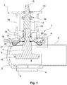
- a lift valve 1 is shown, which is designed as a single-seat valve.
- the lift valve 1 has a first housing part 2 and a second housing part 3.
- a first connection 4 and a second connection 5 are provided, which are connected to parts of a process plant, in particular pipelines, are designed to be connected and through which an interior space 6 of the lift valve 1 is accessible to a fluid.
- a connection opening 7 is provided, which is formed in the first housing part 2 surrounding the first port 4.
- connection opening 7 is designed to be closable, whereby the fluid connection between the first terminal 4 and the second terminal 5 is switchable.
- a closing element 8 is provided which can be brought to seal the connecting opening 7 and thus a closed position of the lifting valve 1 in sealing contact with a valve seat 9.
- the valve seat 9 is the connecting opening 7 formed surrounding in the wall of the first housing part 2.
- the closing element 8 has a sealing receptacle 10 in which, for example, a seal made of an elastomer is accommodated, which brings about an additional improvement in the sealing properties in the closed position of the lifting valve 1.
- Fig. 1 an open position of the lift valve 1 is shown in which closing element 8 and valve seat 9 are separated from each other and there is a fluid connection between the first port 4 and the second port 5.
- the closing element 8 has a rod section 11 on its side opposite the valve seat 9. This is connected to a valve rod 12, which passes through the second housing part 3 on a sealingly acting housing bushing 13.
- the rod section 11 opposite end of the valve rod 12 is received in a rotary decoupling 14, which is part of a connecting portion 15.
- the rotational decoupling 14 is designed so that the connecting portion 15 and valve rod 12 can rotate against each other, without one of the other set in rotation.
- the connecting portion 15 is connectable to a linear adjustment, not shown. This linear adjustment can be designed as a fluid-operated drive, for example as a pneumatic drive.
- the first housing part 2 has a first flange 16. Against this first flange 16, a second flange 17 is set and both flanges 16 and 17 by means of a suitable connecting means, such as a clamp 18, stretched against each other.
- a suitable connecting means such as a clamp 18, stretched against each other.
- the second housing part 3 has on the side facing away from the second flange 17 a lantern 19 which surrounds the valve rod 12.
- the lantern 19 terminates in a third flange 20, by means of which a connection with a housing of the aforementioned, not shown here linear adjustment can be produced.
- the lift valve 1 is designed for aseptic working conditions in that a diaphragm 21 creates a seal of the inner space 6 against the first and second flange 16 and 17 and against the housing passage 13.
- the membrane 21 is arranged for this purpose between the first housing 2 and the rod portion 11 of the closing element 8.
- a higher fluid pressure than in the vicinity of the lift valve 1 occur.
- an inner support body 22 and an outer support body 23 are provided, to which portions of the diaphragm 21 can create depending on the switching position of the lift valve.
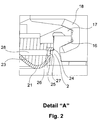
- the attachment of the diaphragm 21 to the housing of the lift valve 1 is enlarged in the section A in Fig. 2 shown.
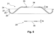
- the membrane 21 is as a single part in Fig. 5 shown in section.
- the membrane 21 is divided in its radial extent into several sections.
- the radially outer portion is a ring 24, to which radially inwardly directly a sleeve 25 connects. Ring 24 and sleeve 25 are held in a gap between the outer support body 23 and the first housing part 2.
- the ring 24 is clamped while the sleeve 25 is guided.
- the clamping is effected indirectly by the clamp 18, which presses first flange 16 and second flange 17 against each other.
- the second flange 17 exerts an axial force on the second support body 23.
- Material and thickness of the membrane 21, dimensions of outer support body 23 and housing part 2 and their position to each other are chosen and dimensioned so that the membrane 21 is elastically compressible deformed.
- a conical portion 26 clamped between outer support body 23 and housing 2 is preferably provided.
- At least one passage 27 is provided, preferably a plurality of passages are distributed over the circumference.
- a fluid may enter the holder of the membrane 21 as so-called leakage in the event of a malfunction along the conical section 26 and the sleeve 25.
- Through the passage 27 enters the Leak through the membrane 21 therethrough.
- the leak has passed through the outer support body 23 through at least one channel 28, so that the leakage is made visible.
- several channels are distributed over the circumference.
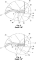
- FIG. 3 The attachment of the membrane 21 on the closing element 8 is in FIG. 3 and FIG. 4 shown as detail B in an enlarged view, wherein Fig. 4 a further education shows.
- Fig. 5 For clarity membrane 21 and washer 29 are shown individually in section.
- a receptacle is provided on the closing element 8.
- This receptacle is formed by a first planar wall 30, a second planar wall 31 and a radial wall 32.
- the first planar wall 30 is located on the inner support body 22. Further limiting part of the receptacle is the second planar wall 31, which on the rod portion 11th the closing element 8 is provided.
- the first wall 30 and the second wall 31 are substantially annular in their basic form and limit the reception in the axial direction Z.
- the receptacle is bounded by the radial wall 32, which is preferably substantially cylindrical in shape and formed on the rod section 11.
- the recording membrane 21 and washer 29 are added. Both are in touching contact with each other.
- the washer 29 is disposed on the side of the diaphragm 21, which faces the inner support body 22 in the axial direction Z.
- a flat clamping surface 33 of the membrane 21 contacts the first planar wall 30 and the washer 29 is in touching contact with the second planar wall 31.
- the diaphragm 21 has a central opening 34 and the washer 29 has a central hole 35. Central opening 34 and central hole 35 are made Fig. 5 easier to see.
- the dimensions, in particular the free diameter, of the central opening 34 and the central hole 35 are dimensioned so that the radial wall 32 causes a guide of the diaphragm 21 and washer 29 in the radial direction R.
- the slippage of membrane 21 and washer 29 is to manufacturing tolerances limited in the manufacture of membrane 21, washer 29 and radial wall 32.
- the rod portion 11 and the inner support body 22 are dimensioned to one another in their shape and position such that the diaphragm 21 and washer 29 are at least safely guided in the receptacle.
- Shape and position of rod portion 11 and inner support body 22 relate in particular to the resulting spatial association of first planar wall 30 and second planar wall 31 to each other.
- the shape and position are dimensioned so that membrane 21 and washer 29 are pressed together with volume change in the recording.
- a material of high dimensional stability and with a temperature resistance of at least 130 ° C is used for the membrane 21 or the washer 29 or both. Due to the dimensional stability, it is possible to dispense with the support means connected to the membrane 21, for example. Support membranes.
- the material has a high media resistance.
- it should have a low creep behavior and preferably have a compressibility of at least 20%, better 25%, advantageously more than 30% according to ASTM F36.
- it may be a composite of multiple layers containing polytetrafluoroethylene (PTFE), wherein one or a plurality of the layers may contain a filler, for example, silicon oxide. This material advantageously has a reversible, elastic-compressible behavior.
- first planar wall 30 and second planar wall 31 When using a material having these described properties, it is advantageous to dimension the distance from first planar wall 30 and second planar wall 31 to effect clamping so that diaphragm 21 or washer 29 or both maximizes 2/3 of the nominal free membrane thickness M or free washer thickness N is compressed.
- the dimensions of the receptacle, the membrane 21 and the washer 29 and a uniform load of the diaphragm 21 and washer 29 in operation are achieved by using similar material for membrane 21 and washer 29. Similar means in this context that strength properties, change in volume when exposed to heat, media and forces as well as the chemical resistance differ only so that no difference in component behavior is visible under operating conditions.
- a force is exerted on the diaphragm 21 during the switching operation, which acts in the radial direction R and leads to an expansion of the diaphragm 21 in this direction. This is transferred to the washer 29.
- a rounding 37 is provided at the transition from second planar wall 32 in an outer wall 36 of the rod portion 11. This avoids a sharp edge which cuts into the washer 29 and scrapes its surface.
- the washer 29 can therefore expand or move in the radial direction R during the load caused by the switching operation of the lift valve 1 out of the receptacle. Sliding membrane 21 and washer 29 against each other is avoided in this way. In addition, gaps are avoided in which dirt can accumulate.
- the outer edge 38 terminates flush with the outer wall 36 of the rod portion 11. This prevents divergence of the diaphragm 21 and washer 29, thereby reducing the possibility of accumulation of contamination.
- the change in shape of the washer 29 is taken into account by the clamping forces. The forces acting in the receptacle on the washer 29 cause an expansion, in particular in the radial direction R.
- the washer 29 is advantageously designed so that it is flush when installed.
- the first level wall 30 of the receptacle has a first elevation 39.
- This survey is pressed in the assembled state of the lift valve 1 in the membrane 21 and causes on the one hand a local increase in the clamping force and on the other hand a positive connection. Both improve the retention of the membrane 21 by improved definition of the position of the membrane 21 in the receptacle.
- This advantage is increased when a second elevation 40 is provided on the second plane wall 31, which is pressed into the washer 29. With the second survey 40, the determination of the washer 29 is improved.
- the force flow in the diaphragm 21 and washer 29 by the clamping is improved in terms of the uniformity of the material stress by first elevation 39 and second elevation 40 are arranged opposite one another.
- Fig. 4 shown embodiment of the detail B of the lifting valve 1 refers to the design of the recording in view of the clamping forces.
- the others based Fig. 3 explained design aspects are applicable without being affected.
- the second planar wall 31b is conical.
- the radial extension direction E of the second planar wall 31b forms an angle W with the radial direction R.
- the radial extension direction E is oriented such that the distance between the first planar wall 30 and the second planar wall 31b increases with increasing distance in the radial direction R from one Center of the arrangement decreases.
- the receptacle is thus designed to be tapered in the radial direction R.
- the angle W is such that membrane 21 and washer 29 are compressed to a maximum of two-thirds of their normal strength.
- the distance between the first planar wall 30 or, if present, the first elevation 39 and the highest point P of the second planar wall 31b is two-thirds the sum of free membrane thickness M and free washer thickness N.
- the first planar wall 30 may also be conically shaped at least partially in the region of the receptacle.
- the design of the washer 29 has been shown on a lifting valve 1 with a closing element 8.
- the invention is readily applicable to a lift valve with a plurality of closing elements, which may be carried out independently movable, transferable.
- a double-seat valve has a plurality of closing elements with coaxial with each other, telescopically arranged valve rods, of which the outer has to enforce a housing feedthrough.
Description
Die Erfindung betrifft ein Hubventil mit einer Membran nach dem Oberbegriff des ersten Anspruchs.The invention relates to a lifting valve with a membrane according to the preamble of the first claim.
Eine Gattung der Hubventile ist im Hinblick auf die Verwendung in aseptischen Einsatzfeldern konstruiert, beispielsweise in den Prozessanlagen der Lebensmittel- und Pharmaindustrie. In solchen Hubventilen kommt oft ein Balg zur Abdichtung des Schließelements gegen das Gehäuse zum Einsatz. Auf der Suche nach einer kostengünstigen Alternative zum Balg wurden Hubventile konstruiert, die anstelle des Balges eine Membran aufweisen.One type of globe valves is designed for use in aseptic applications, such as food processing and pharmaceutical process industries. In such lift valves, often a bellows is used to seal the closing element against the housing. In the search for a cost-effective alternative to the bellows, lift valves were designed that have a diaphragm instead of the bellows.
Ein Hubventil mit einer Membran zeigt die
Ein Hubventil für aseptische Anwendungen wird in der
Ein weiteres Hubventil wird in der
In dem Hubventil gemäß
Die
Ein weiteres aseptisches Doppelsitzventil wird in der
In den gezeigten Hubventilen wird die Membran, soweit sie zur Abdichtung einer Durchführung des Schließelements durch ein Gehäuse dient, durch Verformung während des Schaltvorgangs des Ventils belastet. Hinzu kommt, dass eine Einspannung des inneren und äußeren Randes angestrebt ist, die Verschleppung von Produkt in den Klemmspalt praktisch vermeidet. Diese Klemmung bewirkt zusammen mit der hubbedingten Verformung eine Gesamtbelastung der Membran. Im Stand der Technik wurde insbesondere die Einspannung des äußeren Randes der Membran betrachtet und verbessert.In the lift valves shown, the membrane, as far as it serves to seal a passage of the closing element through a housing, loaded by deformation during the switching operation of the valve. In addition, a clamping of the inner and outer edge is sought, the carryover of product in the nip practically avoids. This clamping causes together with the stroke-induced deformation a total load of the membrane. In particular, the clamping of the outer edge of the membrane has been considered and improved in the prior art.
Die
Die
Die
In der
Die
Das Dokument
Es ist daher Aufgabe der Erfindung, die Einspannung des Innenbereichs der Membran so zu verbessern, dass die Belastung der Membran im Betrieb des Hubventils verringert wird.It is therefore an object of the invention to improve the clamping of the inner region of the membrane so that the load on the membrane is reduced during operation of the lift valve.
Diese Aufgabe wird gelöst mit einem Hubventil mit den Merkmalen des Anspruchs 1. Vorteilhafte Weiterbildungen werden in den abhängigen Ansprüchen 2 bis 13 vorgestellt.This object is achieved with a lift valve having the features of
In einem Hubventil, welches eine zwischen einem ersten Anschluss und einem zweiten Anschluss vorgesehene Verbindungsöffnung umfasst, wobei ein Ventilsitz an der Verbindungsöffnung vorgesehen ist, mit welchem ein Schließelement zusammenwirkt, ist eine Gehäusedurchführung vorgesehen, welche von dem Schließelement durchsetzt wird. Diese Gehäusedurchführung wird mittels einer gehäuseseitig gehalterten Membran abgedichtet. Die Membran besitzt eine Zentralöffnung, welche in einer am Schließelement vorgesehenen Aufnahme gehaltert ist. Weiterhin ist eine Unterlegscheibe vorgesehen, welche ein mittiges Loch aufweist. Diese Unterlegscheibe ist auf einer der Gehäusedurchführung abgewandten Seite der Membran zusammen mit der Membran in der Aufnahme angeordnet, wobei Unterlegscheibe und Membran wenigstens abschnittsweise aus gleichartigem Material hergestellt sind. Gleichartig bezieht sich in diesem Zusammenhang insbesondere auf Festigkeitseigenschaften, Volumenänderung und chemische Beständigkeit der Materials.In a lift valve, which comprises a connection opening provided between a first connection and a second connection, wherein a valve seat is provided at the connection opening with which a closure element cooperates, a housing passage is provided, which is penetrated by the closure element. This housing feedthrough is sealed by means of a membrane-mounted membrane on the housing side. The membrane has a central opening, which is held in a receptacle provided on the closing element. Furthermore, a washer is provided, which has a central hole. This washer is arranged on a side facing away from the housing passage of the membrane together with the membrane in the receptacle, wherein washer and membrane at least partially from similar Material are made. Similar refers in this context in particular strength properties, volume change and chemical resistance of the material.
Der Druck des Fluides, welches durch einen der Anschlüsse in das Hubventil eintritt, wirkt auf die Membran ein. Zusammen mit der Walkarbeit die durch Bewegen des Schließelements beim Schalten des Hubventils entsteht, wird eine Dehnung der Membran bewirkt. Dies bedeutet Zugkräfte sowie Schubspannungen im Material. Dies wird verstärkt, wenn die Membran in der Aufnahme eingespannt ist, da die innere Einspannung einen kleinen Flächentraganteil besitzt. Die Unterlegscheibe bewirkt vorteilhaft eine erhebliche Entlastung der Membran, insbesondere durch die Anordnung auf der Seite, welcher der Gehäusedurchführung abgewandt ist. Die Membran wird insgesamt in der Aufnahme entlastet, jedoch besonders stark am Übergang in die metallische Aufnahme hinein. Durch Verringerung der Materialbelastung wird die Lebensdauer erhöht. Als zusätzlicher Vorteil wird durch die verringerte Alterung der Membran im Bereich der Aufnahme die Reinheit an dieser Stelle erhöht, da die beabsichtige Funktionsweise der Membran erhalten bleibt und verschmutzungsanfällige Schadstellen an der Membran vermieden werden. Der Abschnitt aus gleichartigem Material ist entsprechend dieser beabsichtigten Wirkung zu gestalten, beispielsweise durch eine Materialauflage auf der Unterlegscheibe aus Membranmaterial, die der Membran zugewandt ist.The pressure of the fluid entering the lift valve through one of the ports acts on the diaphragm. Together with the flexing work that is produced by moving the closing element when switching the lifting valve, an expansion of the membrane is effected. This means tensile forces and shear stresses in the material. This is reinforced when the membrane is clamped in the receptacle, since the inner clamping has a small areal contribution. The washer advantageously causes a considerable relief of the membrane, in particular by the arrangement on the side, which faces away from the housing feedthrough. The membrane is relieved overall in the recording, but particularly strong at the transition into the metallic receptacle inside. By reducing the material load life is increased. As an additional advantage, the purity at this point is increased by the reduced aging of the membrane in the region of the recording, since the intended functioning of the membrane is maintained and contamination-prone defects on the membrane are avoided. The section of similar material is to be designed according to this intended effect, for example by a material support on the washer of membrane material, which faces the membrane.
Die Membran weist ein Material mit einer Kompressibilität von wenigstens 20% nach ASTFM 36 auf. Die Unterlegscheibe weist ebenfalls ein Material mit einer Kompressibilität von wenigstens 20% nach ASTFM 36 auf. Der Vorteil ist, dass mit diesem Material eine dauerhaft hohe Formstabilität erreicht wird. Dies bewirkt, dass Klemmkräfte und Dichtwirkung sehr lange konstant bleiben und sich für die Funktion von Membran und/oder Unterlegscheibe vernachlässigbare Änderungen aufweisen.The membrane has a material with a compressibility of at least 20% according to ASTFM 36. The washer also has a material with a compressibility of at least 20% according to ASTFM 36. The advantage is that with this material a permanently high dimensional stability is achieved. This has the effect that clamping forces and sealing effect remain constant for a very long time and have negligible changes in the function of the membrane and / or washer.
Eine Weiterbildung der Aufnahme sieht vor, diese sich radial nach außen hin verjüngend zu gestalten. Es entsteht dadurch eine nach außen zunehmende Flächenpressung, durch die Verschmutzungseintrag in die Aufnahme hinein verhindert und eine gute Klemmung von Membran und Unterlegscheibe bewirkt wird.A further development of the recording provides for this to be tapered radially outward. This results in an outwardly increasing surface pressure, prevents the entry of contamination into the receptacle and good clamping of the membrane and washer is effected.
Eine einfache Herstellung der Aufnahme, die zudem die Membran vorteilhaft gering auf Verschleiß beansprucht, wird gemäß einer Weiterbildung erreicht, indem die Aufnahme eine erste und eine zweite ebene Wand aufweist, die an sich gegenüberliegenden Seiten der Aufnahme vorgesehen sind.A simple production of the recording, which also claims the diaphragm advantageously low on wear, is achieved according to a development by the Receiving a first and a second planar wall, which are provided on opposite sides of the receptacle.
Eine weitere Steigerung der Vorteile wird mit einer Weiterbildung erreicht, die vorsieht, dass wenigstens eine von erster und zweiter Wand der Aufnahme eine Erhebung aufweist. Diese Erhebung drückt sich in Membran und/oder Unterlegscheibe und bewirkt eine Erhöhung der Flächenpressung. Dies verbessert die Klemmung und wirkt gegen Eintrag von Verschmutzung.A further increase of the advantages is achieved with a further development, which provides that at least one of the first and second wall of the receptacle has a survey. This survey is expressed in membrane and / or Washer and causes an increase in the surface pressure. This improves the clamping and acts against contamination.
Diese Vorteile lassen sich erreichen und steigern, wenn die Aufnahme eine erste und eine zweite Erhebung aufweist, die sich ganz oder teilweise gegenüberstehen.These advantages can be achieved and increased if the recording has a first and a second survey, which are completely or partially opposite.
Eine andere Weiterbildung verringert die Materialbeanspruchung durch Dehnung und Bewegung der Unterlegscheibe. Die Verringerung ergibt sich daraus, dass die Aufnahme auf der Seite der Membran, auf der die Unterlegscheibe angeordnet ist, am Übergang der Aufnahme in eine Außenwand des Schließelements eine Abrundung aufweist.Another development reduces the material stress by stretching and movement of the washer. The reduction results from the fact that the recording on the side of the membrane, on which the washer is arranged, at the transition of the receptacle in an outer wall of the closing element has a rounding.
Eine einfache Herstellung des Hubventils und eine geringe Beanspruchung der Membran während der Schaltvorgänge des Hubventils werden erreicht, wenn die Membran eine das mittige Loch umgebende und an das mittige Loch angrenzende ebene Einspannfläche aufweist.A simple manufacture of the lift valve and low stress on the diaphragm during the switching operations of the lift valve are achieved when the membrane has a surrounding the central hole and adjacent to the central hole planar clamping surface.
Durch Führung des mittigen Loches zur Zentrierung der Unterlegscheibe in einer radialen Richtung werden Bewegungen der Unterlegscheibe in der Aufnahme verringert. Dies verringert die Gefahr von Verschmutzung der Aufnahme und verringert die Materialbelastung.By guiding the central hole for centering the washer in a radial direction, movements of the washer in the receptacle are reduced. This reduces the risk of contamination of the receptacle and reduces the material load.
Eine stoffschlüssige Verbindung der Unterlegscheibe mit der Membran verhindert die Reibung der Unterlegscheibe an der Membran und damit Abrieb. Die Möglichkeit der Einwanderung von Schmutz in den Kontaktbereich von Membran und Unterlegscheibe ist weitestgehend ausgeschlossen.A cohesive connection of the washer with the membrane prevents the friction of the washer on the membrane and thus abrasion. The possibility of immigration of dirt in the contact area of membrane and washer is largely excluded.
Dieser Vorteil lässt sich alternativ erreichen, wenn die Unterlegscheibe Teil der Membran ist.This advantage can alternatively be achieved if the washer is part of the membrane.
Ein Auseinanderklaffen von Membran und Unterlegscheibe außerhalb der Aufnahme wird vorteilhaft vermieden indem ein Außenrand der Unterlegscheibe, vorzugsweise im eingebauten Zustand, bündig mit einer Außenwand des Schließelements abschließt. Dies verhindert das Einwandern von Schmutz in den Kontaktbereich von Membran und Unterlegscheibe.A divergence of membrane and washer outside the receptacle is advantageously avoided by an outer edge of the washer, preferably in the installed state, flush with an outer wall of the closing element. This prevents the ingress of dirt into the contact area of membrane and washer.
Vorteilhaft die Klemmwirkung erhöhend und verschmutzungsgefährdete Leerräume verringernd ist eine Gestaltung, nach der ein die Unterlegscheibe aufnehmender Raum der Aufnahme durch die Unterlegscheibe zu etwa 95%, vorzugsweise 100%, gefüllt ist.Advantageously increasing the clamping effect and reducing the risk of voiding voids is a design according to which a washer receiving space of the washer is filled by about 95%, preferably 100%, of the washer.
Materialbeanspruchungen eines der Elemente Membran und Unterlegscheibe auf Kosten des anderen können entstehen, wenn eines von beiden Elementen widerstandsfähiger als das andere ist. Daher sieht eine vorteilhafte Weiterbildung vor, dass Unterlegscheibe und Membran aus dem gleichen Material hergestellt sind.Material stresses on one of the membrane and washer elements at the expense of the other can arise if either element is more resistant than the other. Therefore, an advantageous development provides that washer and membrane are made of the same material.
Anhand eines Ausführungsbeispiels und seiner Weiterbildungen sollen die Erfindung näher erläutert und die Darstellung der Wirkungen und Vorteile vertieft werden.
Es zeigen:
- Fig. 1:
- Längsschnitt durch ein Hubventil mit einer Membran in geöffneter Stellung des Schließelements;
- Fig. 2:
- Ansicht des Details "A": Schnitt durch die Halterung des Außenrandes der Membran;
- Fig. 3:
- Ansicht des Details "B": Schnitt durch die Halterung des Innenrandes der Membran;
- Fig. 4:
- Ansicht des Details "B" in Weiterbildung: Schnitt durch die Halterung des Innenrandes der Membran gemäß einer Weiterbildung;
- Fig. 5:
- Längsschnitt durch Membran und Unterlegscheibe.
Show it:
- Fig. 1:
- Longitudinal section through a lifting valve with a membrane in the open position of the closing element;
- Fig. 2:
- View of detail "A": section through the support of the outer edge of the membrane;
- 3:
- View of detail "B": section through the holder of the inner edge of the membrane;
- 4:
- View of the detail "B" in development: section through the holder of the inner edge of the membrane according to a development;
- Fig. 5:
- Longitudinal section through membrane and washer.
In
Die Verbindungsöffnung 7 ist verschließbar ausgeführt, wodurch die Fluidverbindung zwischen erstem Anschluss 4 und zweitem Anschluss 5 schaltbar ist. Im Innenraum 6 ist ein Schließelement 8 vorgesehen, welches zum Verschließen der Verbindungsöffnung 7 und damit einer Schließstellung des Hubventils 1 in dichtenden Kontakt mit einem Ventilsitz 9 bringbar ist. Der Ventilsitz 9 ist die Verbindungsöffnung 7 umgebend in der Wandung des ersten Gehäuseteils 2 ausgebildet. Das Schließelement 8 weist eine Dichtungsaufnahme 10 auf, in der beispielsweise eine Dichtung aus einem Elastomer aufgenommen ist, welcher eine zusätzliche Verbesserung der Dichteigenschaften in der Schließstellung des Hubventils 1 bewirkt. In
Das Schließelement 8 weist auf seiner dem Ventilsitz 9 gegenüberliegenden Seite einen Stangenabschnitt 11 auf. Dieser ist mit einer Ventilstange 12 verbunden, welche das zweite Gehäuseteil 3 an einer dichtend wirkenden Gehäusedurchführung 13 durchsetzt. Das dem Stangenabschnitt 11 entgegengesetzte Ende der Ventilstange 12 ist in einer Drehentkopplung 14 aufgenommen, welche Teil eines Verbindungsabschnitts 15 ist. Die Drehentkopplung 14 ist so ausgeführt, dass sich Verbindungsabschnitt 15 und Ventilstange 12 gegeneinander verdrehen können, ohne dass der eine den anderen in Drehung versetzt. Der Verbindungsabschnitt 15 ist mit einer nicht gezeigten Linearverstellung verbindbar. Diese Linearverstellung kann als druckmittelbetriebener Antrieb, beispielsweise als pneumatischer Antrieb, ausgeführt sein.The
Das erste Gehäuseteil 2 weist einen ersten Flansch 16 auf. Gegen diesen ersten Flansch 16 wird ein zweiter Flansch 17 gesetzt und beide Flansche 16 und 17 mittels eines geeigneten Verbindungsmittels, beispielsweise einer Klammer 18, gegeneinander gespannt.The
Das zweite Gehäuseteil 3 besitzt auf der dem zweiten Flansch 17 abgewandten Seite eine Laterne 19, die die Ventilstange 12 umgibt. Die Laterne 19 endet in einem dritten Flansch 20, mittels welchem eine Verbindung mit einem Gehäuse der vorgenannten, hier nicht dargestellten Linearverstellung herstellbar ist.The
Das Hubventil 1 ist für aseptische Arbeitsbedingungen ausgelegt, indem eine Membran 21 eine Abdichtung des Innenraumes 6 gegen ersten und zweiten Flansch 16 und 17 sowie gegen die Gehäusedurchführung 13 schafft. Die Membran 21 ist hierzu zwischen erstem Gehäuse 2 und dem Stangenabschnitt 11 des Schließelements 8 angeordnet. Im Innenraum 6 des Hubventils 1 kann ein höherer Fluiddruck als in der Umgebung des Hubventils 1 auftreten. Um daraus entstehende Belastungen der Membran 21 und damit deren Alterung zu reduzieren, sind ein innerer Stützkörper 22 und ein äußerer Stützkörper 23 vorgesehen, an die sich Abschnitte der Membran 21 je nach Schaltstellung des Hubventils anlegen können.The
Die Befestigung der Membran 21 am Gehäuse des Hubventils 1 ist im Ausschnitt A vergrößert in
Die Membran 21 ist in ihrer radialen Erstreckung in mehrere Abschnitte unterteilt. Der radial außenliegende Abschnitt ist ein Ring 24, an den sich radial einwärts unmittelbar eine Hülse 25 anschließt. Ring 24 und Hülse 25 sind in einem Spalt zwischen äußerem Stützkörper 23 und erstem Gehäuseteil 2 gehaltert. Vorzugsweise ist der Ring 24 geklemmt, während die Hülse 25 geführt ist. Die Klemmung wird mittelbar durch die Klammer 18 bewirkt, welche ersten Flansch 16 und zweiten Flansch 17 gegeneinander drückt. Der zweite Flansch 17 übt eine axiale Kraft auf den zweiten Stützkörper 23 aus. Material und Stärke der Membran 21, Abmessungen von äußerem Stützkörper 23 und Gehäuseteil 2 sowie deren Lage zueinander sind so gewählt und bemessen, dass die Membran 21 elastisch kompressibel verformt wird. Sich radial innen an die Hülse anschließend ist vorzugweise ein zwischen äußerem Stützkörper 23 und Gehäuse 2 geklemmter konischer Abschnitt 26 vorgesehen.The
In der Hülse 25 ist wenigstens ein Durchlass 27 vorgesehen, vorzugweise sind mehrere Durchlässe über den Umfang verteilt. Ein Fluid kann als so genannte Leckage im Falle einer Fehlfunktion entlang des konischen Abschnitts 26 und der Hülse 25 in die Halterung der Membran 21 eintreten. Durch den Durchlass 27 tritt die Leckage durch die Membran 21 hindurch. Die hindurchgetretene Leckage wird im äußeren Stützkörper 23 durch wenigstens einen Kanal 28 weitergeleitet, so dass die Leckage sichtbar gemacht wird. Vorzugweise sind mehrere Kanäle über den Umfang verteilt. Durch geeignete Gestaltung der Gehäusedurchführung 13 wird die Leckage aus dem Kanal 28 in den Bereich der Laterne 19 geführt, so dass sie für den Benutzer des Hubventils 1 sichtbar wird.In the
Die Befestigung der Membran 21 am Schließelement 8 ist in
Zur Festlegung und Halterung der Membran 21 ist am Schließelement 8 eine Aufnahme vorgesehen. Diese Aufnahme wird gebildet durch eine erste ebene Wand 30, eine zweite ebene Wand 31 und eine radiale Wand 32. Die erste ebene Wand 30 befindet sich am inneren Stützkörper 22. Weiterer begrenzender Teil der Aufnahme ist die zweite ebene Wand 31, die am Stangenabschnitt 11 des Schließelements 8 vorgesehen ist. Erste Wand 30 und zweite Wand 31 sind in ihrer Grundform im Wesentlichen ringförmig und begrenzen die Aufnahme in axialer Richtung Z. In radialer Richtung R wird die Aufnahme von der radialen Wand 32 begrenzt, die vorzugsweise weitgehend zylindrisch geformt und am Stangenabschnitt 11 ausgebildet ist.To fix and hold the
In der Aufnahme sind Membran 21 und Unterlegscheibe 29 aufgenommen. Beide stehen in berührendem Kontakt miteinander. Die Unterlegscheibe 29 ist auf der Seite der Membran 21 angeordnet, die in axialer Richtung Z dem inneren Stützkörper 22 gegenüberliegt. Eine ebene Einspannfläche 33 der Membran 21 berührt die erste ebene Wand 30 und die Unterlegscheibe 29 steht in berührendem Kontakt mit der zweiten ebenen Wand 31. Die Membran 21 besitzt eine Zentralöffnung 34 und die Unterlegscheibe 29 ein mittiges Loch 35. Zentralöffnung 34 und mittiges Loch 35 sind aus
Die Abmessungen, insbesondere der freie Durchmesser, von Zentralöffnung 34 und mittigem Loch 35 sind so bemessen, dass die radiale Wand 32 eine Führung von Membran 21 und Unterlegscheibe 29 in radialer Richtung R bewirkt. Insbesondere ist das Verrutschen von Membran 21 und Unterlegscheibe 29 auf Fertigungstoleranzen bei der Fertigung von Membran 21, Unterlegscheibe 29 und radialer Wand 32 beschränkt.The dimensions, in particular the free diameter, of the
Der Stangenabschnitt 11 und der innere Stützkörper 22 sind in ihrer Form und Lage zueinander derart bemessen, dass Membran 21 und Unterlegscheibe 29 wenigstens sicher in der Aufnahme geführt sind. Form und Lage von Stangenabschnitt 11 und innerem Stützkörper 22 beziehen sich insbesondere auf die sich ergebende räumliche Zuordnung von erster ebener Wand 30 und zweiter ebener Wand 31 zueinander. Vorzugsweise sind Form und Lage so bemessen, dass Membran 21 und Unterlegscheibe 29 mit Volumenänderung zusammengedrückt in der Aufnahme eingeklemmt sind.The
Vorzugsweise wird für die Membran 21 oder die Unterlegscheibe 29 oder für beide ein Material hoher Formstabilität und mit einer Temperaturbeständigkeit von wenigstens 130°C eingesetzt. Durch die Formstabilität ist es möglich, auf mit der Membran 21 verbundene Stützmittel, bspw. Stützmembranen, zu verzichten. Vorzugsweise weist das Material eine hohe Medienbeständigkeit auf. Insbesondere soll es ein geringes Kriechverhalten aufweisen und vorzugsweise eine Kompressibilität von wenigstens 20%, besser 25%, vorteilhaft mehr als 30% nach ASTM F36 besitzen. Es kann sich beispielsweise um einen Verbund von mehreren, Polytetrafluorethylen (PTFE) enthaltenden Schichten handeln, wobei eine oder eine Mehrzahl der Schichten einen Füllstoff enthalten kann, beispielsweise Siliziumoxid. Dieses Material besitzt vorteilhaft ein reversibles, elastisch-kompressibles Verhalten. Bei Verwendung eines Materials mit diesen beschriebenen Eigenschaften ist es vorteilhaft, den Abstand von erster ebener Wand 30 und zweiter ebener Wand 31 zum Bewirken einer Klemmung so zu bemessen, dass Membran 21 oder Unterlegscheibe 29 oder beide auf maximal 2/3 der nominellen freien Membranstärke M bzw. freien Unterlegscheibenstärke N zusammengepresst wird.Preferably, a material of high dimensional stability and with a temperature resistance of at least 130 ° C is used for the
Die Abmessungen der Aufnahme, der Membran 21 und der Unterlegscheibe 29 sowie eine gleichmäßige Belastung von Membran 21 und Unterlegscheibe 29 im Betrieb werden durch Benutzung von gleichartigem Material für Membran 21 und Unterlegscheibe 29 erreicht. Gleichartig bedeutet in diesem Zusammenhang, dass Festigkeitseigenschaften, Volumenänderung bei Einwirken von Wärme, Medien und Kräften sowie die chemische Beständigkeit nur so voneinander abweichen, dass unter Betriebsbedingungen kein Unterschied im Bauteilverhalten sichtbar ist.The dimensions of the receptacle, the
Im Betrieb wird beim Schaltvorgang eine Kraft auf die Membran 21 ausgeübt, die in radialer Richtung R wirkt und zu einer Dehnung der Membran 21 in dieser Richtung führt. Dies wird auf die Unterlegscheibe 29 übertragen. Um Materialabrieb sehr stark zu verringern, ist am Übergang von zweiter ebener Wand 32 in eine Außenwand 36 des Stangenabschnitts 11 eine Abrundung 37 vorgesehen. Hierdurch wird eine scharfe Kante vermieden, die in die Unterlegscheibe 29 schneidet und deren Oberfläche schabt.In operation, a force is exerted on the
Ein bezogen auf die radiale Richtung R außen gelegener Außenrand 38 der Unterlegscheibe 29 ist freiliegend angeordnet und steht daher im Kontakt mit dem das Hubventil 1 durchströmende Fluid. Die Unterlegscheibe 29 kann sich daher in radialer Richtung R während der durch den Umschaltvorgang des Hubventils 1 hervorgerufenen Belastung aus der Aufnahme heraus ausdehnen oder bewegen. Gleiten von Membran 21 und Unterlegscheibe 29 gegeneinander wird auf diese Weise vermieden. Zudem werden Spalte vermieden, in denen sich Verschmutzung einlagern kann. Der Außenrand 38 schließt bündig mit der Außenwand 36 des Stangenabschnitts 11 ab. Dies verhindert ein Auseinanderklaffen von Membran 21 und Unterlegscheibe 29 und verringert damit die Möglichkeit zur Ansammlung von Verschmutzung. Vorteilhaft wird die Formänderung der Unterlegscheibe 29 durch die Einspannkräfte berücksichtigt. Die in der Aufnahme auf die Unterlegscheibe 29 einwirkenden Kräfte bewirken eine Ausdehnung insbesondere in radialer Richtung R. Die Unterlegscheibe 29 ist vorteilhaft so gestaltet, dass sie im eingebauten Zustand bündig abschließt.An
Die erste Ebene Wand 30 der Aufnahme weist eine erste Erhebung 39 auf. Diese Erhebung ist im zusammengebauten Zustand des Hubventils 1 in die Membran 21 hineingedrückt und bewirkt zum einen eine lokale Erhöhung der Klemmkraft und zum anderen einen Formschluss. Beides verbessert die Halterung der Membran 21 durch verbesserte Festlegung der Lage der Membran 21 in der Aufnahme. Dieser Vorteil wird erhöht, wenn auf der zweiten Ebenen Wand 31 eine zweite Erhebung 40 vorgesehen ist, die in die Unterlegscheibe 29 hineingedrückt ist. Mit der zweiten Erhebung 40 wird die Festlegung der Unterlegscheibe 29 verbessert.The
Die Abdichtung von Membran 21, Unterlegscheibe 29 und zweiter ebener Wand 31 und damit die Widerstandsfähigkeit der Anordnung gegen Verschmutzung werden verbessert, wenn die zweite Erhebung 40 an die Abrundung 37 angrenzend angeordnet ist.The sealing of
Der Kraftfluss in Membran 21 und Unterlegscheibe 29 durch die Klemmung wird in Bezug auf die Gleichmäßigkeit der Materialbeanspruchung verbessert, indem erste Erhebung 39 und zweite Erhebung 40 sich gegenüberstehend angeordnet sind.The force flow in the
Die in
Anstelle einer Erhebung ist die zweite ebene Wand 31b konisch ausgeführt. Die radiale Erstreckungsrichtung E der zweiten ebenen Wand 31b bildet einen Winkel W mit der radialen Richtung R. Die radiale Erstreckungsrichtung E ist dabei so orientiert, dass der Abstand zwischen erster ebener Wand 30 und zweiter ebener Wand 31b mit zunehmendem Abstand in radialer Richtung R von einer Mitte der Anordnung abnimmt. Die Aufnahme ist somit sich in radialer Richtung R verjüngend ausgeführt. Der Winkel W ist so bemessen, dass Membran 21 und Unterlegscheibe 29 im Maximum auf Zweidrittel ihrer normalen Stärke zusammengepresst werden. Der Abstand zwischen erster ebener Wand 30 oder, soweit vorhanden, erster Erhebung 39 und höchstem Punkt P der zweiten ebenen Wand 31b beträgt Zweidrittel der Summe aus freier Membranstärke M und freier Unterlegscheibenstärke N.Instead of a survey, the second
Anstelle der ersten Erhebung 39 kann auch die erste ebene Wand 30 wenigstens teilweise im Bereich der Aufnahme konisch geformt sein.Instead of the
Die Gestaltung der Unterlegscheibe 29 wurde an ein einem Hubventil 1 mit einem Schließelement 8 gezeigt. Die Erfindung ist ohne weiteres auf ein Hubventil mit mehreren Schließelementen, die auch unabhängig voneinander bewegbar ausgeführt sein können, übertragbar. Beispielsweise besitzt ein Doppelsitzventil mehrere Schließelemente mit koaxial zueinander, teleskopartig ineinander angeordneten Ventilstangen, von denen die äußere eine Gehäusedurchführung durchsetzen muss.The design of the
- 11
- Hubventilglobe valve
- 22
- erstes Gehäuseteilfirst housing part
- 33
- zweites Gehäuseteilsecond housing part
- 44
- erster Anschlussfirst connection
- 55
- zweiter Anschlusssecond connection
- 66
- Innenrauminner space
- 77
- Verbindungsöffnungconnecting opening
- 88th
- Schließelementclosing element
- 99
- Ventilsitzvalve seat
- 1010
- Dichtungsaufnahmeseal Housing
- 1111
- Stangenabschnittslug
- 1212
- Ventilstangevalve rod
- 1313
- GehäusedurchführungCase management
- 1414
- Drehentkopplungrotary decoupling
- 1515
- Verbindungsabschnittconnecting portion
- 1616
- erster Flanschfirst flange
- 1717
- zweiter Flanschsecond flange
- 1818
- Klammerclip
- 1919
- LaterneLantern
- 2020
- dritter Flanschthird flange
- 2121
- Membranmembrane
- 2222
- innerer Stützkörperinner support body
- 2323
- äußerer Stützkörperouter support body
- 2424
- Ringring
- 2525
- Hülseshell
- 2626
- konischer Abschnittconical section
- 2727
- Durchlasspassage
- 2828
- Kanalchannel
- 2929
- Unterlegscheibewasher
- 3030
- erste ebene Wandfirst level wall
- 3131
- zweite ebene Wandsecond level wall
- 31b31b
- zweite ebene Wandsecond level wall
- 3232
- radiale Wandradial wall
- 3333
- ebene Einspannflächelevel clamping surface
- 3434
- Zentralöffnungcentral opening
- 3535
- mittiges Lochcentral hole
- 3636
- Außenwandouter wall
- 3737
- Abrundungrounding off
- 3838
- Außenrandouter edge
- 3939
- erste Erhebungfirst survey
- 4040
- zweite Erhebungsecond survey
- AA
- Detail "A": äußere EinspannungDetail "A": outer clamping
- BB
- Detail "B": innere EinspannungDetail "B": internal clamping
- Ee
- radiale Erstreckungsrichtungradial extension direction
- MM
- freie Membranstärkefree membrane thickness
- NN
- freie Unterlegscheibenstärkeclear washer thickness
- PP
- höchster Punktthe highest point
- RR
- radiale Richtungradial direction
- WW
- Winkelangle
- ZZ
- axiale Richtungaxial direction
Claims (13)
- A poppet valve (1) with a first connection piece (4), a second connection piece (5), a connection opening (7) arranged between the first connection piece (4) and the second connection piece (5), a valve seat (9) provided on the connection opening (7), a casing feed-through (13), a locking element (8), which cooperates with the valve seat (9 and penetrates the casing feed-through (13), a membrane (21) held at the casing side which has a central opening (34) held on the locking element (8) in a seating and which tightens the casing feed-through (13), with a washer (29) having a central hole (35), characterised in that the washer (29) is arranged in the seating together with the membrane (21) at a side of the membrane (21) facing away from the casing feed-through (13) and that the washer (29) and the membrane (21) are made of similar materials at least in sections, wherein the membrane (21) comprises a material with a compressibility of at least 20% according to ASTM F36 and wherein the washer (29) comprises a material with a compressibility of at least 20% according to ASTM F36.
- The poppet valve according to claim 1, characterised in that the seating tapers towards the outside in the radial direction (R).
- A poppet valve according to claim 1 or 2, characterised in that the seating has a first even wall (30) and a second even wall (31; 31b) which are provided on opposing sides of the seating.
- A poppet valve according to one of the preceding claims, characterised in that at least one of the first even wall (30) and the second even wall (31; 31b) has an elevation (39; 40).
- A poppet valve according to one of the preceding claims, characterised in that the seating has a first and a second elevation (39, 40), which completely or partially face each other.
- A poppet valve according to one of the preceding claims, characterised in that on that side of the membrane (21) whereon the washer (29) is arranged, the seating has a rounding (37) on the transition of the seating into an outer wall (36) of the locking element (8).
- A poppet valve according to one of the preceding claims, characterised in that the membrane (23) has an even clamping surface (33), surrounding the central hole (35) and adjacent to the central hole (35).
- A poppet valve according to one of the preceding claims, characterised in that the central hole (35) is guided in a radial direction (R) for centring the washer (29).
- A poppet valve according to one of the preceding claims, characterised in that the washer (29) is substance-bonded to the membrane (21).
- A poppet valve according to one of the claims 1 to 8, characterised in that the washer (29) is a part of the membrane (21).
- A poppet valve according to one of the preceding claims, characterised in that an outer edge (38) of the washer (29) ends flush with an outer edge (36) of the locking element (8).
- A poppet valve according to one of the preceding claims, characterised in that a space of the seating housing the washer (29) is filled by the washer (29) to around 95%, preferably 100%.
- A poppet valve according to one of the preceding claims, characterised in that the washer (29) and the membrane (21) are made of the same material.
Applications Claiming Priority (1)
| Application Number | Priority Date | Filing Date | Title |
|---|---|---|---|
| DE102014010193.2A DE102014010193A1 (en) | 2014-07-10 | 2014-07-10 | Lifting valve with diaphragm |
Publications (2)
| Publication Number | Publication Date |
|---|---|
| EP2966331A1 EP2966331A1 (en) | 2016-01-13 |
| EP2966331B1 true EP2966331B1 (en) | 2018-02-28 |
Family
ID=53510547
Family Applications (1)
| Application Number | Title | Priority Date | Filing Date |
|---|---|---|---|
| EP15001763.0A Active EP2966331B1 (en) | 2014-07-10 | 2015-06-15 | Hydraulic valve with membrane |
Country Status (2)
| Country | Link |
|---|---|
| EP (1) | EP2966331B1 (en) |
| DE (1) | DE102014010193A1 (en) |
Families Citing this family (1)
| Publication number | Priority date | Publication date | Assignee | Title |
|---|---|---|---|---|
| PL3432112T3 (en) * | 2017-07-20 | 2022-04-04 | Danfoss A/S | Valve arrangement for controlling of flow of a heating or cooling fluid |
Family Cites Families (12)
| Publication number | Priority date | Publication date | Assignee | Title |
|---|---|---|---|---|
| US4666166A (en) * | 1984-11-13 | 1987-05-19 | American Standard Inc. | Clamping arrangement for diaphragm-type piston |
| IT1202009B (en) | 1985-07-11 | 1989-02-02 | Rossignoli Renzo | SUPPORT AND SEALING DEVICE FOR TRANSLABLE COMPONENTS PARTICULARLY FOR VALVE GROUPS |
| CN1188619C (en) * | 2000-02-18 | 2005-02-09 | 阿斯科控制装置有限公司 | Extended range proportional valve |
| JP2002188795A (en) * | 2000-12-20 | 2002-07-05 | Kubota Corp | Filling device |
| DE20211511U1 (en) | 2002-07-13 | 2002-12-05 | Flowserve Essen Gmbh | Valve |
| DE202006004173U1 (en) | 2006-03-14 | 2006-10-12 | Kieselmann Gmbh | Aseptic double seat valve has a sealing ring for blocking a gap between rods joined to a connection for a rinsing line |
| DE102006025653C5 (en) | 2006-03-14 | 2010-10-14 | Kieselmann Gmbh | Aseptic double-seat valve |
| DE102007014282A1 (en) * | 2007-03-19 | 2008-10-02 | Südmo Holding GmbH | Valve for separating product media in pipelines of a product-carrying system |
| JP5189543B2 (en) * | 2009-03-30 | 2013-04-24 | 株式会社ケーヒン | Pressure reducing valve |
| AU2013262105B2 (en) | 2012-05-15 | 2016-11-17 | Gea Tuchenhagen Gmbh | Valve and diaphragm for a valve |
| DE102012107992A1 (en) | 2012-08-29 | 2014-03-06 | Südmo Holding GmbH | Aseptic double-seat valve |
| CN203477326U (en) * | 2013-06-28 | 2014-03-12 | 重庆拓源给排水设备有限公司 | Diaphragm mud valve |
-
2014
- 2014-07-10 DE DE102014010193.2A patent/DE102014010193A1/en active Pending
-
2015
- 2015-06-15 EP EP15001763.0A patent/EP2966331B1/en active Active
Non-Patent Citations (1)
| Title |
|---|
| None * |
Also Published As
| Publication number | Publication date |
|---|---|
| DE102014010193A1 (en) | 2016-01-14 |
| EP2966331A1 (en) | 2016-01-13 |
Similar Documents
| Publication | Publication Date | Title |
|---|---|---|
| EP2850351B1 (en) | Valve and diaphragm for a valve | |
| EP2488776B1 (en) | Pressure retaining valve | |
| EP2510266B1 (en) | Multi-way valve | |
| DE102006032082A1 (en) | Valve for substantially gas-tight interruption of a flow path | |
| DE112010003557T5 (en) | butterfly valve | |
| DE3413698A1 (en) | SEALING DEVICE, IN PARTICULAR FOR USE IN A PNEUMATIC SPRING | |
| EP3271623B1 (en) | Lifting valve having a rotational decoupling device | |
| EP1705411B1 (en) | Fast switching pneumatic valve | |
| DE102013200533B4 (en) | VALVE CARTRIDGE | |
| EP3978751B1 (en) | Composite membrane for membrane pumps | |
| EP3183481B1 (en) | Seal ring for axially sealing two parts arranged so as to be able to move axially with respect to one another, and seal system having the seal ring | |
| DE1303585B (en) | Pressure chamber seal for a hydraulic rotary actuator | |
| DE102016219720A1 (en) | pressure valve | |
| EP2966331B1 (en) | Hydraulic valve with membrane | |
| EP3699462B1 (en) | Valve seat cage arrangement | |
| WO2019034401A1 (en) | Seal arrangement | |
| DE202015104151U1 (en) | Control valve | |
| WO2019025045A1 (en) | Shut-off device comprising a sealing device | |
| EP1703185B1 (en) | Coaxial valve | |
| EP3631258B1 (en) | Diaphragm-sealed double-seat valve and drive | |
| EP3714993B1 (en) | Device for outputting a medium capable of flow | |
| DE102019211917B4 (en) | Seal design to prevent damage from explosive pressure relief | |
| DE102010055430B4 (en) | Flap valve and seal for a flap valve | |
| DE102023117369A1 (en) | Ball valve of a refrigerant valve device for an air conditioning system | |
| DE2553383C2 (en) |
Legal Events
| Date | Code | Title | Description |
|---|---|---|---|
| PUAI | Public reference made under article 153(3) epc to a published international application that has entered the european phase |
Free format text: ORIGINAL CODE: 0009012 |
|
| AK | Designated contracting states |
Kind code of ref document: A1 Designated state(s): AL AT BE BG CH CY CZ DE DK EE ES FI FR GB GR HR HU IE IS IT LI LT LU LV MC MK MT NL NO PL PT RO RS SE SI SK SM TR |
|
| AX | Request for extension of the european patent |
Extension state: BA ME |
|
| 17P | Request for examination filed |
Effective date: 20160623 |
|
| RBV | Designated contracting states (corrected) |
Designated state(s): AL AT BE BG CH CY CZ DE DK EE ES FI FR GB GR HR HU IE IS IT LI LT LU LV MC MK MT NL NO PL PT RO RS SE SI SK SM TR |
|
| REG | Reference to a national code |
Ref country code: DE Ref legal event code: R079 Ref document number: 502015003156 Country of ref document: DE Free format text: PREVIOUS MAIN CLASS: F16K0041100000 Ipc: F16K0041120000 |
|
| GRAP | Despatch of communication of intention to grant a patent |
Free format text: ORIGINAL CODE: EPIDOSNIGR1 |
|
| RIC1 | Information provided on ipc code assigned before grant |
Ipc: F16K 41/12 20060101AFI20171110BHEP |
|
| INTG | Intention to grant announced |
Effective date: 20171208 |
|
| GRAS | Grant fee paid |
Free format text: ORIGINAL CODE: EPIDOSNIGR3 |
|
| GRAA | (expected) grant |
Free format text: ORIGINAL CODE: 0009210 |
|
| AK | Designated contracting states |
Kind code of ref document: B1 Designated state(s): AL AT BE BG CH CY CZ DE DK EE ES FI FR GB GR HR HU IE IS IT LI LT LU LV MC MK MT NL NO PL PT RO RS SE SI SK SM TR |
|
| REG | Reference to a national code |
Ref country code: GB Ref legal event code: FG4D Free format text: NOT ENGLISH Ref country code: CH Ref legal event code: EP |
|
| REG | Reference to a national code |
Ref country code: AT Ref legal event code: REF Ref document number: 974540 Country of ref document: AT Kind code of ref document: T Effective date: 20180315 |
|
| REG | Reference to a national code |
Ref country code: IE Ref legal event code: FG4D Free format text: LANGUAGE OF EP DOCUMENT: GERMAN |
|
| REG | Reference to a national code |
Ref country code: DE Ref legal event code: R096 Ref document number: 502015003156 Country of ref document: DE |
|
| REG | Reference to a national code |
Ref country code: FR Ref legal event code: PLFP Year of fee payment: 4 |
|
| REG | Reference to a national code |
Ref country code: NL Ref legal event code: MP Effective date: 20180228 |
|
| REG | Reference to a national code |
Ref country code: LT Ref legal event code: MG4D |
|
| REG | Reference to a national code |
Ref country code: CH Ref legal event code: NV Representative=s name: ISLER AND PEDRAZZINI AG, CH |
|
| PG25 | Lapsed in a contracting state [announced via postgrant information from national office to epo] |
Ref country code: FI Free format text: LAPSE BECAUSE OF FAILURE TO SUBMIT A TRANSLATION OF THE DESCRIPTION OR TO PAY THE FEE WITHIN THE PRESCRIBED TIME-LIMIT Effective date: 20180228 Ref country code: NO Free format text: LAPSE BECAUSE OF FAILURE TO SUBMIT A TRANSLATION OF THE DESCRIPTION OR TO PAY THE FEE WITHIN THE PRESCRIBED TIME-LIMIT Effective date: 20180528 Ref country code: CY Free format text: LAPSE BECAUSE OF FAILURE TO SUBMIT A TRANSLATION OF THE DESCRIPTION OR TO PAY THE FEE WITHIN THE PRESCRIBED TIME-LIMIT Effective date: 20180228 Ref country code: NL Free format text: LAPSE BECAUSE OF FAILURE TO SUBMIT A TRANSLATION OF THE DESCRIPTION OR TO PAY THE FEE WITHIN THE PRESCRIBED TIME-LIMIT Effective date: 20180228 Ref country code: LT Free format text: LAPSE BECAUSE OF FAILURE TO SUBMIT A TRANSLATION OF THE DESCRIPTION OR TO PAY THE FEE WITHIN THE PRESCRIBED TIME-LIMIT Effective date: 20180228 Ref country code: HR Free format text: LAPSE BECAUSE OF FAILURE TO SUBMIT A TRANSLATION OF THE DESCRIPTION OR TO PAY THE FEE WITHIN THE PRESCRIBED TIME-LIMIT Effective date: 20180228 Ref country code: ES Free format text: LAPSE BECAUSE OF FAILURE TO SUBMIT A TRANSLATION OF THE DESCRIPTION OR TO PAY THE FEE WITHIN THE PRESCRIBED TIME-LIMIT Effective date: 20180228 |
|
| PG25 | Lapsed in a contracting state [announced via postgrant information from national office to epo] |
Ref country code: BG Free format text: LAPSE BECAUSE OF FAILURE TO SUBMIT A TRANSLATION OF THE DESCRIPTION OR TO PAY THE FEE WITHIN THE PRESCRIBED TIME-LIMIT Effective date: 20180528 Ref country code: GR Free format text: LAPSE BECAUSE OF FAILURE TO SUBMIT A TRANSLATION OF THE DESCRIPTION OR TO PAY THE FEE WITHIN THE PRESCRIBED TIME-LIMIT Effective date: 20180529 Ref country code: RS Free format text: LAPSE BECAUSE OF FAILURE TO SUBMIT A TRANSLATION OF THE DESCRIPTION OR TO PAY THE FEE WITHIN THE PRESCRIBED TIME-LIMIT Effective date: 20180228 Ref country code: LV Free format text: LAPSE BECAUSE OF FAILURE TO SUBMIT A TRANSLATION OF THE DESCRIPTION OR TO PAY THE FEE WITHIN THE PRESCRIBED TIME-LIMIT Effective date: 20180228 Ref country code: SE Free format text: LAPSE BECAUSE OF FAILURE TO SUBMIT A TRANSLATION OF THE DESCRIPTION OR TO PAY THE FEE WITHIN THE PRESCRIBED TIME-LIMIT Effective date: 20180228 |
|
| PG25 | Lapsed in a contracting state [announced via postgrant information from national office to epo] |
Ref country code: MT Free format text: LAPSE BECAUSE OF FAILURE TO SUBMIT A TRANSLATION OF THE DESCRIPTION OR TO PAY THE FEE WITHIN THE PRESCRIBED TIME-LIMIT Effective date: 20180228 |
|
| PG25 | Lapsed in a contracting state [announced via postgrant information from national office to epo] |
Ref country code: PL Free format text: LAPSE BECAUSE OF FAILURE TO SUBMIT A TRANSLATION OF THE DESCRIPTION OR TO PAY THE FEE WITHIN THE PRESCRIBED TIME-LIMIT Effective date: 20180228 Ref country code: EE Free format text: LAPSE BECAUSE OF FAILURE TO SUBMIT A TRANSLATION OF THE DESCRIPTION OR TO PAY THE FEE WITHIN THE PRESCRIBED TIME-LIMIT Effective date: 20180228 Ref country code: RO Free format text: LAPSE BECAUSE OF FAILURE TO SUBMIT A TRANSLATION OF THE DESCRIPTION OR TO PAY THE FEE WITHIN THE PRESCRIBED TIME-LIMIT Effective date: 20180228 Ref country code: IT Free format text: LAPSE BECAUSE OF FAILURE TO SUBMIT A TRANSLATION OF THE DESCRIPTION OR TO PAY THE FEE WITHIN THE PRESCRIBED TIME-LIMIT Effective date: 20180228 Ref country code: AL Free format text: LAPSE BECAUSE OF FAILURE TO SUBMIT A TRANSLATION OF THE DESCRIPTION OR TO PAY THE FEE WITHIN THE PRESCRIBED TIME-LIMIT Effective date: 20180228 |
|
| REG | Reference to a national code |
Ref country code: DE Ref legal event code: R097 Ref document number: 502015003156 Country of ref document: DE |
|
| PG25 | Lapsed in a contracting state [announced via postgrant information from national office to epo] |
Ref country code: SK Free format text: LAPSE BECAUSE OF FAILURE TO SUBMIT A TRANSLATION OF THE DESCRIPTION OR TO PAY THE FEE WITHIN THE PRESCRIBED TIME-LIMIT Effective date: 20180228 Ref country code: DK Free format text: LAPSE BECAUSE OF FAILURE TO SUBMIT A TRANSLATION OF THE DESCRIPTION OR TO PAY THE FEE WITHIN THE PRESCRIBED TIME-LIMIT Effective date: 20180228 Ref country code: SM Free format text: LAPSE BECAUSE OF FAILURE TO SUBMIT A TRANSLATION OF THE DESCRIPTION OR TO PAY THE FEE WITHIN THE PRESCRIBED TIME-LIMIT Effective date: 20180228 Ref country code: CZ Free format text: LAPSE BECAUSE OF FAILURE TO SUBMIT A TRANSLATION OF THE DESCRIPTION OR TO PAY THE FEE WITHIN THE PRESCRIBED TIME-LIMIT Effective date: 20180228 |
|
| PLBE | No opposition filed within time limit |
Free format text: ORIGINAL CODE: 0009261 |
|
| STAA | Information on the status of an ep patent application or granted ep patent |
Free format text: STATUS: NO OPPOSITION FILED WITHIN TIME LIMIT |
|
| 26N | No opposition filed |
Effective date: 20181129 |
|
| PG25 | Lapsed in a contracting state [announced via postgrant information from national office to epo] |
Ref country code: SI Free format text: LAPSE BECAUSE OF FAILURE TO SUBMIT A TRANSLATION OF THE DESCRIPTION OR TO PAY THE FEE WITHIN THE PRESCRIBED TIME-LIMIT Effective date: 20180228 |
|
| REG | Reference to a national code |
Ref country code: BE Ref legal event code: MM Effective date: 20180630 |
|
| REG | Reference to a national code |
Ref country code: IE Ref legal event code: MM4A |
|
| PG25 | Lapsed in a contracting state [announced via postgrant information from national office to epo] |
Ref country code: LU Free format text: LAPSE BECAUSE OF NON-PAYMENT OF DUE FEES Effective date: 20180615 Ref country code: MC Free format text: LAPSE BECAUSE OF FAILURE TO SUBMIT A TRANSLATION OF THE DESCRIPTION OR TO PAY THE FEE WITHIN THE PRESCRIBED TIME-LIMIT Effective date: 20180228 |
|
| PG25 | Lapsed in a contracting state [announced via postgrant information from national office to epo] |
Ref country code: IE Free format text: LAPSE BECAUSE OF NON-PAYMENT OF DUE FEES Effective date: 20180615 |
|
| PG25 | Lapsed in a contracting state [announced via postgrant information from national office to epo] |
Ref country code: BE Free format text: LAPSE BECAUSE OF NON-PAYMENT OF DUE FEES Effective date: 20180630 |
|
| PG25 | Lapsed in a contracting state [announced via postgrant information from national office to epo] |
Ref country code: TR Free format text: LAPSE BECAUSE OF FAILURE TO SUBMIT A TRANSLATION OF THE DESCRIPTION OR TO PAY THE FEE WITHIN THE PRESCRIBED TIME-LIMIT Effective date: 20180228 |
|
| PG25 | Lapsed in a contracting state [announced via postgrant information from national office to epo] |
Ref country code: PT Free format text: LAPSE BECAUSE OF FAILURE TO SUBMIT A TRANSLATION OF THE DESCRIPTION OR TO PAY THE FEE WITHIN THE PRESCRIBED TIME-LIMIT Effective date: 20180228 |
|
| PG25 | Lapsed in a contracting state [announced via postgrant information from national office to epo] |
Ref country code: MK Free format text: LAPSE BECAUSE OF NON-PAYMENT OF DUE FEES Effective date: 20180228 Ref country code: HU Free format text: LAPSE BECAUSE OF FAILURE TO SUBMIT A TRANSLATION OF THE DESCRIPTION OR TO PAY THE FEE WITHIN THE PRESCRIBED TIME-LIMIT; INVALID AB INITIO Effective date: 20150615 |
|
| PG25 | Lapsed in a contracting state [announced via postgrant information from national office to epo] |
Ref country code: IS Free format text: LAPSE BECAUSE OF FAILURE TO SUBMIT A TRANSLATION OF THE DESCRIPTION OR TO PAY THE FEE WITHIN THE PRESCRIBED TIME-LIMIT Effective date: 20180628 |
|
| REG | Reference to a national code |
Ref country code: AT Ref legal event code: MM01 Ref document number: 974540 Country of ref document: AT Kind code of ref document: T Effective date: 20200615 |
|
| PG25 | Lapsed in a contracting state [announced via postgrant information from national office to epo] |
Ref country code: AT Free format text: LAPSE BECAUSE OF NON-PAYMENT OF DUE FEES Effective date: 20200615 |
|
| P01 | Opt-out of the competence of the unified patent court (upc) registered |
Effective date: 20230601 |
|
| PGFP | Annual fee paid to national office [announced via postgrant information from national office to epo] |
Ref country code: FR Payment date: 20230620 Year of fee payment: 9 |
|
| PGFP | Annual fee paid to national office [announced via postgrant information from national office to epo] |
Ref country code: GB Payment date: 20230622 Year of fee payment: 9 Ref country code: CH Payment date: 20230702 Year of fee payment: 9 |
|
| PGFP | Annual fee paid to national office [announced via postgrant information from national office to epo] |
Ref country code: DE Payment date: 20230810 Year of fee payment: 9 |