EP2966310A1 - Roller bearing cage - Google Patents
Roller bearing cage Download PDFInfo
- Publication number
- EP2966310A1 EP2966310A1 EP14760723.8A EP14760723A EP2966310A1 EP 2966310 A1 EP2966310 A1 EP 2966310A1 EP 14760723 A EP14760723 A EP 14760723A EP 2966310 A1 EP2966310 A1 EP 2966310A1
- Authority
- EP
- European Patent Office
- Prior art keywords
- connecting member
- segment
- diameter
- segments
- roller bearing
- Prior art date
- Legal status (The legal status is an assumption and is not a legal conclusion. Google has not performed a legal analysis and makes no representation as to the accuracy of the status listed.)
- Granted
Links
- 238000000926 separation method Methods 0.000 claims abstract description 7
- 238000003754 machining Methods 0.000 claims description 3
- 239000002184 metal Substances 0.000 claims description 3
- 229910052751 metal Inorganic materials 0.000 claims description 3
- RYGMFSIKBFXOCR-UHFFFAOYSA-N Copper Chemical compound [Cu] RYGMFSIKBFXOCR-UHFFFAOYSA-N 0.000 claims description 2
- CWYNVVGOOAEACU-UHFFFAOYSA-N Fe2+ Chemical compound [Fe+2] CWYNVVGOOAEACU-UHFFFAOYSA-N 0.000 claims description 2
- 229910052802 copper Inorganic materials 0.000 claims description 2
- 239000010949 copper Substances 0.000 claims description 2
- 238000003825 pressing Methods 0.000 claims description 2
- 230000002265 prevention Effects 0.000 claims 2
- 238000000034 method Methods 0.000 description 4
- 238000010248 power generation Methods 0.000 description 3
- 229910000831 Steel Inorganic materials 0.000 description 2
- 238000007689 inspection Methods 0.000 description 2
- 238000004519 manufacturing process Methods 0.000 description 2
- 239000010959 steel Substances 0.000 description 2
- 239000004696 Poly ether ether ketone Substances 0.000 description 1
- JUPQTSLXMOCDHR-UHFFFAOYSA-N benzene-1,4-diol;bis(4-fluorophenyl)methanone Chemical compound OC1=CC=C(O)C=C1.C1=CC(F)=CC=C1C(=O)C1=CC=C(F)C=C1 JUPQTSLXMOCDHR-UHFFFAOYSA-N 0.000 description 1
- 230000003247 decreasing effect Effects 0.000 description 1
- 230000000694 effects Effects 0.000 description 1
- 230000003100 immobilizing effect Effects 0.000 description 1
- 239000000463 material Substances 0.000 description 1
- 229920002530 polyetherether ketone Polymers 0.000 description 1
- 239000011347 resin Substances 0.000 description 1
- 229920005989 resin Polymers 0.000 description 1
- 238000005096 rolling process Methods 0.000 description 1
- 238000003466 welding Methods 0.000 description 1
Images



Classifications
-
- F—MECHANICAL ENGINEERING; LIGHTING; HEATING; WEAPONS; BLASTING
- F16—ENGINEERING ELEMENTS AND UNITS; GENERAL MEASURES FOR PRODUCING AND MAINTAINING EFFECTIVE FUNCTIONING OF MACHINES OR INSTALLATIONS; THERMAL INSULATION IN GENERAL
- F16C—SHAFTS; FLEXIBLE SHAFTS; ELEMENTS OR CRANKSHAFT MECHANISMS; ROTARY BODIES OTHER THAN GEARING ELEMENTS; BEARINGS
- F16C33/00—Parts of bearings; Special methods for making bearings or parts thereof
- F16C33/30—Parts of ball or roller bearings
- F16C33/46—Cages for rollers or needles
- F16C33/50—Cages for rollers or needles formed of interconnected members, e.g. chains
- F16C33/502—Cages for rollers or needles formed of interconnected members, e.g. chains formed of arcuate segments retaining one or more rollers or needles
-
- F—MECHANICAL ENGINEERING; LIGHTING; HEATING; WEAPONS; BLASTING
- F16—ENGINEERING ELEMENTS AND UNITS; GENERAL MEASURES FOR PRODUCING AND MAINTAINING EFFECTIVE FUNCTIONING OF MACHINES OR INSTALLATIONS; THERMAL INSULATION IN GENERAL
- F16C—SHAFTS; FLEXIBLE SHAFTS; ELEMENTS OR CRANKSHAFT MECHANISMS; ROTARY BODIES OTHER THAN GEARING ELEMENTS; BEARINGS
- F16C19/00—Bearings with rolling contact, for exclusively rotary movement
- F16C19/22—Bearings with rolling contact, for exclusively rotary movement with bearing rollers essentially of the same size in one or more circular rows, e.g. needle bearings
- F16C19/34—Bearings with rolling contact, for exclusively rotary movement with bearing rollers essentially of the same size in one or more circular rows, e.g. needle bearings for both radial and axial load
- F16C19/36—Bearings with rolling contact, for exclusively rotary movement with bearing rollers essentially of the same size in one or more circular rows, e.g. needle bearings for both radial and axial load with a single row of rollers
- F16C19/361—Bearings with rolling contact, for exclusively rotary movement with bearing rollers essentially of the same size in one or more circular rows, e.g. needle bearings for both radial and axial load with a single row of rollers with cylindrical rollers
-
- F—MECHANICAL ENGINEERING; LIGHTING; HEATING; WEAPONS; BLASTING
- F16—ENGINEERING ELEMENTS AND UNITS; GENERAL MEASURES FOR PRODUCING AND MAINTAINING EFFECTIVE FUNCTIONING OF MACHINES OR INSTALLATIONS; THERMAL INSULATION IN GENERAL
- F16C—SHAFTS; FLEXIBLE SHAFTS; ELEMENTS OR CRANKSHAFT MECHANISMS; ROTARY BODIES OTHER THAN GEARING ELEMENTS; BEARINGS
- F16C19/00—Bearings with rolling contact, for exclusively rotary movement
- F16C19/22—Bearings with rolling contact, for exclusively rotary movement with bearing rollers essentially of the same size in one or more circular rows, e.g. needle bearings
- F16C19/34—Bearings with rolling contact, for exclusively rotary movement with bearing rollers essentially of the same size in one or more circular rows, e.g. needle bearings for both radial and axial load
- F16C19/36—Bearings with rolling contact, for exclusively rotary movement with bearing rollers essentially of the same size in one or more circular rows, e.g. needle bearings for both radial and axial load with a single row of rollers
- F16C19/364—Bearings with rolling contact, for exclusively rotary movement with bearing rollers essentially of the same size in one or more circular rows, e.g. needle bearings for both radial and axial load with a single row of rollers with tapered rollers, i.e. rollers having essentially the shape of a truncated cone
-
- F—MECHANICAL ENGINEERING; LIGHTING; HEATING; WEAPONS; BLASTING
- F16—ENGINEERING ELEMENTS AND UNITS; GENERAL MEASURES FOR PRODUCING AND MAINTAINING EFFECTIVE FUNCTIONING OF MACHINES OR INSTALLATIONS; THERMAL INSULATION IN GENERAL
- F16C—SHAFTS; FLEXIBLE SHAFTS; ELEMENTS OR CRANKSHAFT MECHANISMS; ROTARY BODIES OTHER THAN GEARING ELEMENTS; BEARINGS
- F16C33/00—Parts of bearings; Special methods for making bearings or parts thereof
- F16C33/30—Parts of ball or roller bearings
- F16C33/46—Cages for rollers or needles
- F16C33/4611—Cages for rollers or needles with hybrid structure, i.e. with parts made of distinct materials
-
- F—MECHANICAL ENGINEERING; LIGHTING; HEATING; WEAPONS; BLASTING
- F16—ENGINEERING ELEMENTS AND UNITS; GENERAL MEASURES FOR PRODUCING AND MAINTAINING EFFECTIVE FUNCTIONING OF MACHINES OR INSTALLATIONS; THERMAL INSULATION IN GENERAL
- F16C—SHAFTS; FLEXIBLE SHAFTS; ELEMENTS OR CRANKSHAFT MECHANISMS; ROTARY BODIES OTHER THAN GEARING ELEMENTS; BEARINGS
- F16C43/00—Assembling bearings
- F16C43/04—Assembling rolling-contact bearings
-
- F—MECHANICAL ENGINEERING; LIGHTING; HEATING; WEAPONS; BLASTING
- F16—ENGINEERING ELEMENTS AND UNITS; GENERAL MEASURES FOR PRODUCING AND MAINTAINING EFFECTIVE FUNCTIONING OF MACHINES OR INSTALLATIONS; THERMAL INSULATION IN GENERAL
- F16C—SHAFTS; FLEXIBLE SHAFTS; ELEMENTS OR CRANKSHAFT MECHANISMS; ROTARY BODIES OTHER THAN GEARING ELEMENTS; BEARINGS
- F16C2300/00—Application independent of particular apparatuses
- F16C2300/10—Application independent of particular apparatuses related to size
- F16C2300/14—Large applications, e.g. bearings having an inner diameter exceeding 500 mm
-
- F—MECHANICAL ENGINEERING; LIGHTING; HEATING; WEAPONS; BLASTING
- F16—ENGINEERING ELEMENTS AND UNITS; GENERAL MEASURES FOR PRODUCING AND MAINTAINING EFFECTIVE FUNCTIONING OF MACHINES OR INSTALLATIONS; THERMAL INSULATION IN GENERAL
- F16C—SHAFTS; FLEXIBLE SHAFTS; ELEMENTS OR CRANKSHAFT MECHANISMS; ROTARY BODIES OTHER THAN GEARING ELEMENTS; BEARINGS
- F16C2360/00—Engines or pumps
- F16C2360/31—Wind motors
Definitions
- the present invention relates to a retainer for use in a large roller bearing, particularly in a tapered roller bearing which is utilized to support a main shaft in a wind power-generator, and also for use in a large tapered roller bearing which has an outer diameter in excess of one meter for example, used in industrial equipment.
- a tapered roller bearing may include a retainer, a cage usually made from a steel plate.
- the retainer integrates an inner ring and rolling elements with each other.
- an ultra-large tapered roller bearing which is often used as a main bearing in the field of wind power-generation, it is difficult to make a single-piece retainer from a steel plate.
- a welded retainer which includes support rods inserted through hollow rollers, and two side plates welded to the support rods.
- Another alternative is a segmented (divided) retainer which requires special fabrication method using dedicated jigs.
- Patent Literature 1 in retainers used in large tapered roller bearings, an immobilizing member is arranged with a segmented retainer or a separated retainer on a circumference to prevent separation during assembly, for improved handling and assemblability.
- Patent Literature 3 discloses an arrangement that a segmented retainer is immobilized by a ring member in order to prevent the segmented retainer from breaking apart during assembly.
- Patent Literature 3 raises a similar problem that it is difficult to make the ring member for ultra-large sizes.
- the present invention provides a roller bearing retainer constituted by two or a greater number of circumferentially disposed segments.
- Each segment includes: a plurality of columns between mutually opposing long sides of a rectangle; and a plurality of pockets for holding rollers between the columns.
- At least one of the mutually opposing long sides of the segment is fitted, in a circumferentially slidable fashion, into an arc-shaped connecting member which has a generally U-shaped section.
- the segments are arranged in the circumferential direction, and then the connecting member of each segment is slid over the long side of the adjacent segment for mutual connection of the segments.
- the roller bearing retainer according to the present invention can be assembled to an outer circumference of an inner ring without breaking apart.
- the arc-shaped connecting member may have a circumferential length equal to a length of the long side of the segment if not longer than that, or the long side of the segment may be divided into a plurality of portions.
- the arc-shaped connecting member which has the same circumferential length as the long side of the segment gives advantages of decreased number of parts and ease of handling.
- the segments which are assembled onto the outer circumference of the inner ring can be easily removed by sliding back so as not to ride on the adjacent segment. This makes it easy to perform inspections.
- segments of an identical design are arranged into an annular shape, only one jig and only one metal mold are enough when responding to demand.
- Fig. 1 shows part of a large tapered roller bearing which is used in supporting a main shaft in wind power-generation equipment for example.
- the tapered roller bearing includes an inner ring 11, an outer ring 12 disposed coaxially around an outer circumference thereof, tapered rollers 15 disposed between an inner ring track 13 of the inner ring 11 and an outer ring track 14 of the outer ring 12 opposed thereto, and a retainer 16 which keeps a constant space between the tapered rollers 15.
- the tapered rollers 15 used in a large tapered roller bearing for supporting, e.g., a main shaft in wind power-generation equipment has a diameter not smaller than 40 mm, and the bearing has an outer diameter not smaller than 1 m.
- the inner ring 11 has a small flange region 17 formed on a small-diameter side of the inner ring track 13, and a large flange region 18 formed on a large-diameter side thereof. These flange regions 17, 18 guide rotating movement of the tapered rollers 15. On an axially outer side of the small flange region 17 and of the large flange region 18, a small-diameter region 19 and a large-diameter region 20 are formed respectively.
- the retainer 16 is constituted by a plurality of circumferentially divided segments 21. By annularly arranging these segments 21, there is fabricated a retainer which looks like a basket having a shape of a truncated cone.
- the segment 21 is like a frame, including a plurality (six, in the illustrated embodiment, including two at a left and a right ends) of columns 31 provided between mutually opposing long sides of a rectangle. Pockets 32 (five, in the illustrated embodiment) are formed between the columns 31. Each pocket 32 accepts and holds one tapered roller 15.
- One of the two long arc-shaped sides of the segment 21 which is faced by a small-diameter end of the tapered roller 15 will be called small-diameter side 33a, whereas the other faced by a large-diameter end will be called large-diameter side 33b.
- each arc portion 31a holds two tapered rollers 15 on its sides (see Fig. 6 ).
- the small-diameter side 33a and the large-diameter side 33b of the segments 21 are respectively formed with a small-diameter-side engager 34a and a large-diameter-side engager 34b each protruding axially outward of the segments 21 and having a tip edge curved in parallel with the axis. As shown in Fig. 7 and Fig.
- the small-diameter-side engager 34a and the large-diameter-side engager 23 are respectively fitted, in a circumferentially slidable fashion, into a small-diameter-side connecting member 35a and a large-diameter-side connecting member 35b which have the same circumferential length as the small-diameter-side engager 34a and the large-diameter-side engager 34b respectively and a generally U-shaped section.
- the segments 21 are arranged in a circumferential direction, and under this state, the small-diameter-side connecting member 35a and the large-diameter-side connecting member 35b of each segment 21 are slid over the small-diameter-side engager 34a and the large-diameter-side engager 34b of the adjacent segment respectively as shown in Fig. 4 and Fig. 8 .
- the segments 21 arranged in the circumferential direction are connected to each other, and therefore separation of the segments 21 during an assembling process is prevented.
- the small-diameter-side connecting member 35a and the large-diameter-side connecting member 35b both having a U-shaped section, have their tip edge regions formed with mutually opposing salients 36.
- the salients 36 fit into re-entrant grooves 37 formed in both upper and lower surfaces of the small-diameter-side engager 34a and the large-diameter-side engager 34b in the segment 21.
- the salients 36 and the re-entrant grooves 37 fit to each other, whereby the small-diameter-side connecting member 35a and the large-diameter-side connecting member 35b which have a U-shaped section are made axially non-slippable with respect to the small-diameter-side engager 34a and the large-diameter-side engager 34b of the segment 21.
- an engagement recess 38 as shown in Circle A in Fig. 7 and in an enlarged view in Fig. 9 .
- the engagement recess 38 is fitted by an engagement projection 39 which is formed at each end of the salients 36 as shown in Circle B in Fig. 7 and in an enlarged view in Fig. 10 .
- the engagement recess 38 and the engagement projection 39 come into engagement when the small-diameter-side connecting member 35a and the large-diameter-side connecting member 35b are circumferentially slid by half their length as shown in Fig. 4 , on the small-diameter-side engager 34a and the large-diameter-side engager 34b of the segments 21. In this way, the small-diameter-side connecting member 35a and the large-diameter-side connecting member 35b of the segments 21 are brought to their predetermined circumferential positions.
- the small-diameter-side connecting member 35a and the large-diameter-side connecting member 35b of the segments 21 can be formed by machining or pressing a copper or a ferrous metal (e.g., SPCC and SUS).
- a copper or a ferrous metal e.g., SPCC and SUS.
- the segments 21 can be formed of a resin material such as PEEK, PPS, PA (66 or 46).
- Forming the engagement projection 39 at both ends of the salient 36 in each of the small-diameter-side connecting member 35a and the large-diameter-side connecting member 35b increases fitting with the re-entrant groove 37 which is formed in the small-diameter-side connecting member 35a and the large-diameter-side connecting member 35b of the segments 21.
- the small-diameter-side connecting member 35a and the large-diameter-side connecting member 35b can slide more smoothly.
- the segments 21 in the embodiment described thus far are first placed in an annular pattern as shown in Fig. 2 and Fig. 3 , on an outer circumference of the inner ring 11; and then as shown in Fig. 4 , the small-diameter-side connecting member 35a and the large-diameter-side connecting member 35b are slid over the small-diameter-side engager 34a and the large-diameter-side engager 34b of the adjacent segment 21. This ensures that the segments 21 arranged in an annular pattern are assembled to the outer circumference of the inner ring 11 without breaking apart.
- the segments 21 which are assembled onto the outer circumference of the inner ring 11 can be easily removed: As shown in Fig. 3 , the small-diameter-side connecting member 35a and the large-diameter-side connecting member 35b are moved back so that they do not ride on the small-diameter-side engager 34a and the large-diameter-side engager 34b of the adjacent segment 21. Then, as shown in Fig. 2 , it becomes possible to disassemble the segments 21 from the outer circumference of the inner ring 11. This makes it easy to perform inspections.
- the small-diameter side 33a and the large-diameter side 33b of the segments 21 are respectively formed with an arc-shaped small-diameter-side engager 34a and an arc-shaped large-diameter-side engager 34b, and the small-diameter-side engager 34a and the large-diameter-side engager 23 are respectively fitted into a small-diameter-side connecting member 35a and a large-diameter-side connecting member 35b which have a generally U-shaped section, in a circumferentially slidable fashion.
- the small-diameter-side connecting member 35a and the large-diameter-side connecting member 35b, each having a generally U-shaped section have the same circumferential lengths as the circumferential lengths of the small-diameter side 33a and the large-diameter side 33b of the segments 21.
- the small-diameter-side connecting member 35a and the large-diameter-side connecting member 35b, each having a generally U-shaped section may be circumferentially divided into a plurality.
- the small-diameter-side connecting member 35a and the large-diameter-side connecting member 35b, each having a generally U-shaped section are divided into three.
Landscapes
- Engineering & Computer Science (AREA)
- General Engineering & Computer Science (AREA)
- Mechanical Engineering (AREA)
- Rolling Contact Bearings (AREA)
Abstract
Description
- The present invention relates to a retainer for use in a large roller bearing, particularly in a tapered roller bearing which is utilized to support a main shaft in a wind power-generator, and also for use in a large tapered roller bearing which has an outer diameter in excess of one meter for example, used in industrial equipment.
- A tapered roller bearing may include a retainer, a cage usually made from a steel plate. The retainer integrates an inner ring and rolling elements with each other. In an ultra-large tapered roller bearing which is often used as a main bearing in the field of wind power-generation, it is difficult to make a single-piece retainer from a steel plate.
- As an alternative, therefore, there is proposed a welded retainer which includes support rods inserted through hollow rollers, and two side plates welded to the support rods. Another alternative is a segmented (divided) retainer which requires special fabrication method using dedicated jigs.
- The first alternative has a problem of welding cost while the second alternative has a problem of handling difficulty. The second alternative, which was found to have some cost advantage, was improved further. As found in Patent Literature 1 and Patent Literature 2, in retainers used in large tapered roller bearings, an immobilizing member is arranged with a segmented retainer or a separated retainer on a circumference to prevent separation during assembly, for improved handling and assemblability. Also, Patent Literature 3 discloses an arrangement that a segmented retainer is immobilized by a ring member in order to prevent the segmented retainer from breaking apart during assembly.
-
- Patent Literature 1:
JP-A 2009-63102 - Patent Literature 2:
JP-A 2007-064437 - Patent Literature 3:
JP-A 2011-149549 - A problem, however, with the segmented retainer according to Patent Literature 1 and the separator retainer according to Patent Literature 2 is the ring members which are used to prevent separation. For ultra-large sizes, machining on the ring members requires a substantial cost and also is difficult. Another problem is that since the ring member is fixed to an inner ring, dimension control in fitting areas is difficult, and assembling of the ring members is also difficult.
- The alternative disclosed in Patent Literature 3 raises a similar problem that it is difficult to make the ring member for ultra-large sizes.
- It is therefore an object of the present invention to prevent separation of a segmented retainer at the time of assembly, without utilizing an ultra-large size ring member which is difficult to make.
- As a solution to the problems described above, the present invention provides a roller bearing retainer constituted by two or a greater number of circumferentially disposed segments. Each segment includes: a plurality of columns between mutually opposing long sides of a rectangle; and a plurality of pockets for holding rollers between the columns. At least one of the mutually opposing long sides of the segment is fitted, in a circumferentially slidable fashion, into an arc-shaped connecting member which has a generally U-shaped section. The segments are arranged in the circumferential direction, and then the connecting member of each segment is slid over the long side of the adjacent segment for mutual connection of the segments.
- By placing the segments on the outer circumference of the inner ring first, and then sliding the arc-shaped connecting member over the long side of the adjacent segment, the roller bearing retainer according to the present invention can be assembled to an outer circumference of an inner ring without breaking apart.
- The arc-shaped connecting member may have a circumferential length equal to a length of the long side of the segment if not longer than that, or the long side of the segment may be divided into a plurality of portions. The arc-shaped connecting member which has the same circumferential length as the long side of the segment gives advantages of decreased number of parts and ease of handling.
- Also, the segments which are assembled onto the outer circumference of the inner ring can be easily removed by sliding back so as not to ride on the adjacent segment. This makes it easy to perform inspections.
- According to the present invention it is possible to prevent separation of segments during assembly, without utilizing an ultra-large size ring member which is difficult to manufacture.
- Also, since segments of an identical design are arranged into an annular shape, only one jig and only one metal mold are enough when responding to demand.
-
-
Fig. 1 is a sectional view which shows an application of the present invention to a tapered roller bearing. -
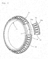
Fig. 2 is a perspective view which shows an assembling procedure of segments of the tapered roller bearing inFig. 1 . -
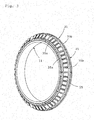
Fig. 3 is a perspective view which shows a state before a connecting member of the segment is slid to establish connection. -
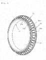
Fig. 4 is a perspective view which shows a state where the connecting member of the segment is slid and connection is established. -
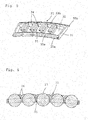
Fig. 5 is a perspective view of a segment with rollers removed. -
Fig. 6 is a vertical sectional view which shows a state where rollers are held by the segments. -
Fig. 7 is a perspective view which shows a state where the connecting member of the segment is removed. -
Fig. 8 is a perspective view which shows a state where the connecting member inFig. 7 is slid from the segment. -
Fig. 9 is an enlarged perspective view of a region in Circle A inFig. 7 . -
Fig. 10 is an enlarged perspective view of a region in Circle B inFig. 7 . -
Fig. 11 is a perspective view which shows an assembling procedure of segments of a tapered roller bearing in a second embodiment of the present invention. -
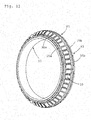
Fig. 12 is a perspective view which shows a state where a connecting member of a segment in the embodiment inFig. 11 is slid and connection is established. - Hereinafter, embodiments of the present invention will be described based on the attached drawings.
-
Fig. 1 shows part of a large tapered roller bearing which is used in supporting a main shaft in wind power-generation equipment for example. The tapered roller bearing includes aninner ring 11, anouter ring 12 disposed coaxially around an outer circumference thereof,tapered rollers 15 disposed between aninner ring track 13 of theinner ring 11 and anouter ring track 14 of theouter ring 12 opposed thereto, and aretainer 16 which keeps a constant space between thetapered rollers 15. - On an average, the
tapered rollers 15 used in a large tapered roller bearing for supporting, e.g., a main shaft in wind power-generation equipment, has a diameter not smaller than 40 mm, and the bearing has an outer diameter not smaller than 1 m. - The
inner ring 11 has asmall flange region 17 formed on a small-diameter side of theinner ring track 13, and alarge flange region 18 formed on a large-diameter side thereof. Theseflange regions tapered rollers 15. On an axially outer side of thesmall flange region 17 and of thelarge flange region 18, a small-diameter region 19 and a large-diameter region 20 are formed respectively. - As shown in
Fig. 2 through Fig. 4 , theretainer 16 is constituted by a plurality of circumferentially dividedsegments 21. By annularly arranging thesesegments 21, there is fabricated a retainer which looks like a basket having a shape of a truncated cone. - As shown in
Fig. 5 , thesegment 21 is like a frame, including a plurality (six, in the illustrated embodiment, including two at a left and a right ends) ofcolumns 31 provided between mutually opposing long sides of a rectangle. Pockets 32 (five, in the illustrated embodiment) are formed between thecolumns 31. Eachpocket 32 accepts and holds onetapered roller 15. One of the two long arc-shaped sides of thesegment 21 which is faced by a small-diameter end of thetapered roller 15 will be called small-diameter side 33a, whereas the other faced by a large-diameter end will be called large-diameter side 33b. - Of the six
columns 31, fourcolumns 31 at intermediate locations, excluding the two at the ends, have their top ends formed with a Y-shaped arc portion 31a (seeFig. 5 ). Eacharc portion 31a holds twotapered rollers 15 on its sides (seeFig. 6 ). - The small-
diameter side 33a and the large-diameter side 33b of thesegments 21 are respectively formed with a small-diameter-side engager 34a and a large-diameter-side engager 34b each protruding axially outward of thesegments 21 and having a tip edge curved in parallel with the axis. As shown inFig. 7 andFig. 8 , the small-diameter-side engager 34a and the large-diameter-side engager 23 are respectively fitted, in a circumferentially slidable fashion, into a small-diameter-side connecting member 35a and a large-diameter-side connecting member 35b which have the same circumferential length as the small-diameter-side engager 34a and the large-diameter-side engager 34b respectively and a generally U-shaped section. - As shown in
Fig. 2 andFig. 3 , thesegments 21 are arranged in a circumferential direction, and under this state, the small-diameter-side connecting member 35a and the large-diameter-side connecting member 35b of eachsegment 21 are slid over the small-diameter-side engager 34a and the large-diameter-side engager 34b of the adjacent segment respectively as shown inFig. 4 andFig. 8 . As a result, thesegments 21 arranged in the circumferential direction are connected to each other, and therefore separation of thesegments 21 during an assembling process is prevented. - As shown in
Fig. 7 andFig. 9 , the small-diameter-side connecting member 35a and the large-diameter-side connecting member 35b, both having a U-shaped section, have their tip edge regions formed with mutually opposingsalients 36. Thesalients 36 fit intore-entrant grooves 37 formed in both upper and lower surfaces of the small-diameter-side engager 34a and the large-diameter-side engager 34b in thesegment 21. Thesalients 36 and there-entrant grooves 37 fit to each other, whereby the small-diameter-side connecting member 35a and the large-diameter-side connecting member 35b which have a U-shaped section are made axially non-slippable with respect to the small-diameter-side engager 34a and the large-diameter-side engager 34b of thesegment 21. - In addition, at a circumferentially intermediate position in the
re-entrant groove 37 in both surfaces in each of the small-diameter-side engager 34a and the large-diameter-side engager 34b, there is formed anengagement recess 38 as shown in Circle A inFig. 7 and in an enlarged view inFig. 9 . Theengagement recess 38 is fitted by anengagement projection 39 which is formed at each end of thesalients 36 as shown in Circle B inFig. 7 and in an enlarged view inFig. 10 . Theengagement recess 38 and theengagement projection 39 come into engagement when the small-diameter-side connecting member 35a and the large-diameter-side connecting member 35b are circumferentially slid by half their length as shown inFig. 4 , on the small-diameter-side engager 34a and the large-diameter-side engager 34b of thesegments 21. In this way, the small-diameter-side connecting member 35a and the large-diameter-side connecting member 35b of thesegments 21 are brought to their predetermined circumferential positions. - The small-diameter-
side connecting member 35a and the large-diameter-side connecting member 35b of thesegments 21 can be formed by machining or pressing a copper or a ferrous metal (e.g., SPCC and SUS). Once theengagement projection 39 is fitted into theengagement recess 38, both ends of the small-diameter-side connecting member 35a and of the large-diameter-side connecting member 35b in thesegments 21 are radially swaged to fix the small-diameter-side connecting member 35a and the large-diameter-side connecting member 35b to their predetermined circumferential positions and to prevent the small-diameter-side connecting member 35a and the large-diameter-side connecting member 35b from sliding. - The
segments 21 can be formed of a resin material such as PEEK, PPS, PA (66 or 46). - Forming the
engagement projection 39 at both ends of the salient 36 in each of the small-diameter-side connecting member 35a and the large-diameter-side connecting member 35b increases fitting with there-entrant groove 37 which is formed in the small-diameter-side connecting member 35a and the large-diameter-side connecting member 35b of thesegments 21. By setting the gap between the mutually opposedengagement projections 39 in each of the small-diameter-side connecting member 35a and the large-diameter-side connecting member 35b wider than a thickness between two bottom surfaces of there-entrant grooves 37 which are formed in the upper and the lower surfaces of the small-diameter-side connecting member 35a and the large-diameter-side connecting member 35b of thesegments 21, the small-diameter-side connecting member 35a and the large-diameter-side connecting member 35b can slide more smoothly. - The
segments 21 in the embodiment described thus far are first placed in an annular pattern as shown inFig. 2 andFig. 3 , on an outer circumference of theinner ring 11; and then as shown inFig. 4 , the small-diameter-side connecting member 35a and the large-diameter-side connecting member 35b are slid over the small-diameter-side engager 34a and the large-diameter-side engager 34b of theadjacent segment 21. This ensures that thesegments 21 arranged in an annular pattern are assembled to the outer circumference of theinner ring 11 without breaking apart. - The
segments 21 which are assembled onto the outer circumference of theinner ring 11 can be easily removed: As shown inFig. 3 , the small-diameter-side connecting member 35a and the large-diameter-side connecting member 35b are moved back so that they do not ride on the small-diameter-side engager 34a and the large-diameter-side engager 34b of theadjacent segment 21. Then, as shown inFig. 2 , it becomes possible to disassemble thesegments 21 from the outer circumference of theinner ring 11. This makes it easy to perform inspections. - In the embodiment described so far, the small-
diameter side 33a and the large-diameter side 33b of thesegments 21 are respectively formed with an arc-shaped small-diameter-side engager 34a and an arc-shaped large-diameter-side engager 34b, and the small-diameter-side engager 34a and the large-diameter-side engager 23 are respectively fitted into a small-diameter-side connecting member 35a and a large-diameter-side connecting member 35b which have a generally U-shaped section, in a circumferentially slidable fashion. However, there may be an arrangement that only one of the arc-shaped small-diameter-side engager 34a and an arc-shaped large-diameter-side engager 34b is formed correspondingly to the small-diameter-side connecting member 35a or the large-diameter-side connecting member 35b, without forming the other. - In the Embodiment described above, the small-diameter-
side connecting member 35a and the large-diameter-side connecting member 35b, each having a generally U-shaped section, have the same circumferential lengths as the circumferential lengths of the small-diameter side 33a and the large-diameter side 33b of thesegments 21. However, as shown inFig. 11 andFig. 12 , the small-diameter-side connecting member 35a and the large-diameter-side connecting member 35b, each having a generally U-shaped section, may be circumferentially divided into a plurality. In the embodiment shown inFig. 11 andFig. 12 , the small-diameter-side connecting member 35a and the large-diameter-side connecting member 35b, each having a generally U-shaped section, are divided into three. - Although the embodiments described thus far cover applications to tapered roller bearings, the invention is applicable also to retainers for cylindrical roller bearings.
-
- 11
- Inner Ring
- 12
- Outer Ring
- 13, 14
- Track Surfaces
- 15
- Tapered Roller
- 16
- Retainer
- 17
- Small Flange Region
- 18
- Large Flange Region
- 19
- Small-Diameter Region
- 20
- Large-Diameter Region
- 21
- Segment
- 31
- Column
- 31a
- Arc Portion
- 32
- 33a
- Small-Diameter Side
- 33b
- Large-Diameter Side
- 34a
- Small-Diameter-Side Engager
- 34b
- Large-Diameter-Side Engager
- 35a
- Small-Diameter-Side Connecting Member
- 35b
- Large-Diameter-Side Connecting Member
- 36
- Salient
- 37
- Re-Entrant Groove
- 38
- Engagement Recess
- 39
- Engagement Projection
Claims (5)
- A roller bearing retainer comprising two or a greater number of circumferentially disposed segments, each segment including: a plurality of columns between mutually opposing long sides of a rectangle; and a plurality of pockets for holding rollers between the columns; at least one of the mutually opposing long sides of the segment being fitted, in a circumferentially slidable fashion, into an arc-shaped connecting member having a generally U-shaped section; the segments being arranged in the circumferential direction, with the connecting member of each segment slid over the long side of the adjacent segment for mutual connection of the segments.
- The roller bearing retainer according to Claim 1, wherein the arc-shaped connecting member has a circumferential length equal to a circumferential length of the long side of the segment.
- The roller bearing retainer according to Claim 1 or 2, wherein the arc-shaped connecting member which has a generally U-shaped section has a tip edge formed with mutually opposing salients whereas the long side of the segment has its upper and lower surfaces each formed with a re-entrant groove for fitting by one of the salients, for prevention of the connecting member from axial separation by mutual engagement between the salients and the re-entrant grooves.
- The roller bearing retainer according to one of Claims 1 through 3, wherein the arc-shaped connecting member which has a generally U-shaped section has an inner surface formed with an engagement projection whereas the long side of the segments is formed with an engagement recess for fitting by the engagement projection of the connecting member upon sliding of the connecting member in each segment over the long side of the adjacent segment, for circumferential positioning of the connecting member by mutual engagement between the engagement projection and the engagement recess at a time of assembling.
- The roller bearing retainer according to Claim 4, wherein the arc-shaped connecting member which has a generally U-shaped section is formed by machining or pressing a copper or a ferrous metal, the connecting member being swaged, with the engagement projection of the connecting member fitted into the engagement recess of the segment, for prevention of the connecting member from sliding in a circumferential direction.
Applications Claiming Priority (2)
| Application Number | Priority Date | Filing Date | Title |
|---|---|---|---|
| JP2013046615A JP6069037B2 (en) | 2013-03-08 | 2013-03-08 | Roller bearing cage |
| PCT/JP2014/055561 WO2014136816A1 (en) | 2013-03-08 | 2014-03-05 | Roller bearing cage |
Publications (3)
| Publication Number | Publication Date |
|---|---|
| EP2966310A1 true EP2966310A1 (en) | 2016-01-13 |
| EP2966310A4 EP2966310A4 (en) | 2016-10-19 |
| EP2966310B1 EP2966310B1 (en) | 2019-02-13 |
Family
ID=51491328
Family Applications (1)
| Application Number | Title | Priority Date | Filing Date |
|---|---|---|---|
| EP14760723.8A Not-in-force EP2966310B1 (en) | 2013-03-08 | 2014-03-05 | Roller bearing cage |
Country Status (5)
| Country | Link |
|---|---|
| US (1) | US9482280B2 (en) |
| EP (1) | EP2966310B1 (en) |
| JP (1) | JP6069037B2 (en) |
| CN (1) | CN105008736B (en) |
| WO (1) | WO2014136816A1 (en) |
Families Citing this family (20)
| Publication number | Priority date | Publication date | Assignee | Title |
|---|---|---|---|---|
| JP6472686B2 (en) * | 2015-03-16 | 2019-02-20 | Ntn株式会社 | Roller bearing cage |
| USD809033S1 (en) * | 2015-12-28 | 2018-01-30 | Ntn Corporation | Retainer for rolling bearing |
| GB2550420A (en) | 2016-05-20 | 2017-11-22 | Bowman Int Ltd | Rolling element bearing cage |
| US10054156B2 (en) * | 2016-06-26 | 2018-08-21 | Atec Corporation | Synthetic resin retainer for large thrust ball bearings with dry-lubricant and wet-lubricant management systems |
| CN108425950B (en) * | 2017-02-15 | 2021-02-05 | 斯凯孚公司 | Cage segments, segmented cages and bearings |
| DE102019201560A1 (en) | 2019-02-07 | 2020-08-13 | Aktiebolaget Skf | Bearing cage segment with abutting edge for welding |
| DE102019201553A1 (en) | 2019-02-07 | 2020-08-13 | Aktiebolaget Skf | Bearing cage segment with alignment element |
| DE102019201561A1 (en) | 2019-02-07 | 2020-08-13 | Aktiebolaget Skf | Bearing cage segment of a sheet metal cage |
| DE102019201565A1 (en) | 2019-02-07 | 2020-08-13 | Aktiebolaget Skf | Bearing cage segment with an abutting edge in the area of a web to be formed |
| DE102019201554A1 (en) * | 2019-02-07 | 2020-08-13 | Aktiebolaget Skf | Bearing cage segment with welding material point |
| CN110005716B (en) * | 2019-04-30 | 2024-02-27 | 聊城西科自动化设备有限公司 | Self-aligning roller bearing sleeve assembling device and working method thereof |
| EP4343163A4 (en) * | 2021-05-20 | 2025-05-21 | NTN Corporation | Tapered roller bearing |
| WO2022244872A1 (en) * | 2021-05-20 | 2022-11-24 | Ntn株式会社 | Tapered roller bearing |
| DE102021206285A1 (en) | 2021-06-18 | 2022-12-22 | Aktiebolaget Skf | Cage segment for a roller bearing cage |
| DE102021206284A1 (en) | 2021-06-18 | 2022-12-22 | Aktiebolaget Skf | Cage segment for a roller bearing cage |
| DE102021206282A1 (en) | 2021-06-18 | 2022-12-22 | Aktiebolaget Skf | Cage segment for a roller bearing cage |
| DE102022200326A1 (en) | 2022-01-13 | 2023-07-13 | Aktiebolaget Skf | Cage segment for a segment cage |
| DE102022200327A1 (en) | 2022-01-13 | 2023-07-13 | Aktiebolaget Skf | bearing cage |
| JP2024074111A (en) * | 2022-11-18 | 2024-05-30 | Ntn株式会社 | Tapered roller bearing |
| JP2026005902A (en) * | 2024-06-28 | 2026-01-16 | 広東美的電気有限公司 | Bearings and gears |
Family Cites Families (13)
| Publication number | Priority date | Publication date | Assignee | Title |
|---|---|---|---|---|
| GB825689A (en) * | 1956-10-23 | 1959-12-16 | Skf Svenska Kullagerfab Ab | Cage for rolling bodies in rolling bearings |
| JPS5084733A (en) * | 1973-12-03 | 1975-07-08 | ||
| DE2602265C3 (en) * | 1975-01-24 | 1982-09-23 | Giuseppe Milano Sacheli | Rolling element cage for longitudinal guides and method for producing such a cage |
| KR100860544B1 (en) * | 2005-03-14 | 2008-09-26 | 윤석태 | Magnetic fastening device for split roller bearing cage |
| JP2007064437A (en) | 2005-09-01 | 2007-03-15 | Ntn Corp | Tapered roller bearing, side ring for assembling bearing, and method of assembling tapered roller bearing |
| DE102006022951A1 (en) * | 2006-05-17 | 2007-11-22 | Schaeffler Kg | Cage segment for a cage of a rolling bearing |
| JP2009063102A (en) | 2007-09-06 | 2009-03-26 | Ntn Corp | Retainer for rolling bearing, tapered roller bearing, main shaft support structure for wind power generator, method for manufacturing retainer for rolling bearing, and method for assembling rolling bearing |
| DE102008011112A1 (en) * | 2008-02-26 | 2009-08-27 | Schaeffler Kg | Cage for rolling body in antifriction bearing, has bearing rings joined together under formation of bags, and segment of one of bearing rings joined to two segments of another bearing ring, where segments are made of plastic |
| JP2011117545A (en) * | 2009-12-04 | 2011-06-16 | Ntn Corp | Rolling bearing and its retainer |
| JP5757703B2 (en) | 2009-12-25 | 2015-07-29 | Ntn株式会社 | Tapered roller bearing |
| JP2011208700A (en) * | 2010-03-29 | 2011-10-20 | Ntn Corp | Roller bearing |
| JP2012132535A (en) * | 2010-12-24 | 2012-07-12 | Nsk Ltd | Cage for rolling bearing and rolling bearing |
| DE102012206023A1 (en) * | 2012-04-13 | 2013-10-17 | Schaeffler Technologies AG & Co. KG | Rolling bearing cage has transverse webs that are attached to segments of annular disk, which are spaced from joints |
-
2013
- 2013-03-08 JP JP2013046615A patent/JP6069037B2/en not_active Expired - Fee Related
-
2014
- 2014-03-05 US US14/771,605 patent/US9482280B2/en not_active Expired - Fee Related
- 2014-03-05 WO PCT/JP2014/055561 patent/WO2014136816A1/en not_active Ceased
- 2014-03-05 CN CN201480012655.9A patent/CN105008736B/en not_active Expired - Fee Related
- 2014-03-05 EP EP14760723.8A patent/EP2966310B1/en not_active Not-in-force
Also Published As
| Publication number | Publication date |
|---|---|
| US9482280B2 (en) | 2016-11-01 |
| JP2014173657A (en) | 2014-09-22 |
| WO2014136816A1 (en) | 2014-09-12 |
| JP6069037B2 (en) | 2017-01-25 |
| CN105008736B (en) | 2018-01-09 |
| EP2966310B1 (en) | 2019-02-13 |
| US20160010690A1 (en) | 2016-01-14 |
| CN105008736A (en) | 2015-10-28 |
| EP2966310A4 (en) | 2016-10-19 |
Similar Documents
| Publication | Publication Date | Title |
|---|---|---|
| EP2966310B1 (en) | Roller bearing cage | |
| JP5597410B2 (en) | Segmented cage segment and rolling bearing | |
| US10690181B2 (en) | Angular contact roller bearing and method and device for the assembly thereof | |
| EP3121467A1 (en) | Segmented cage for a bearing | |
| JP4517759B2 (en) | Method for manufacturing roller bearing cage | |
| CN104565021B (en) | Taper roll bearing | |
| US3767278A (en) | Cage for rolling bearing assembly | |
| US20160178000A1 (en) | Split cylindrical roller bearing | |
| CN108488227A (en) | Multi-row tapered roller bearing | |
| JP2009052653A (en) | Cylindrical roller bearing | |
| JP6069920B2 (en) | Tapered roller bearing assembly method, assembly jig, and tapered roller bearing | |
| EP3421828B1 (en) | Roller bearing | |
| JP2014185729A (en) | Cage of rolling bearing | |
| JP2013228064A (en) | Rolling bearing | |
| JP6160137B2 (en) | Cylindrical roller bearing | |
| JP2007205456A (en) | Tapered roller bearing | |
| JP2010151211A (en) | Retainer for conical roller bearing, conical roller bearing and method of assembling the same | |
| JP2006118591A (en) | Multi-point contact ball bearing | |
| US10753402B2 (en) | Bearing assembly and bearing cage | |
| US10041533B2 (en) | Bearing having a shim between two ring parts | |
| JP2015148292A (en) | Assembly jig of rolling bearing, rolling bearing, and assembly method of rolling bearing | |
| EP2860414A1 (en) | Conical roller bearing | |
| JP2019060470A (en) | Rolling bearing | |
| JP2024161804A (en) | Cage and roller bearing | |
| JP2014020389A (en) | Assembly method for roller bearing |
Legal Events
| Date | Code | Title | Description |
|---|---|---|---|
| PUAI | Public reference made under article 153(3) epc to a published international application that has entered the european phase |
Free format text: ORIGINAL CODE: 0009012 |
|
| 17P | Request for examination filed |
Effective date: 20150903 |
|
| AK | Designated contracting states |
Kind code of ref document: A1 Designated state(s): AL AT BE BG CH CY CZ DE DK EE ES FI FR GB GR HR HU IE IS IT LI LT LU LV MC MK MT NL NO PL PT RO RS SE SI SK SM TR |
|
| AX | Request for extension of the european patent |
Extension state: BA ME |
|
| DAX | Request for extension of the european patent (deleted) | ||
| A4 | Supplementary search report drawn up and despatched |
Effective date: 20160920 |
|
| RIC1 | Information provided on ipc code assigned before grant |
Ipc: F16C 33/50 20060101AFI20160914BHEP Ipc: F16C 19/36 20060101ALN20160914BHEP |
|
| GRAP | Despatch of communication of intention to grant a patent |
Free format text: ORIGINAL CODE: EPIDOSNIGR1 |
|
| STAA | Information on the status of an ep patent application or granted ep patent |
Free format text: STATUS: GRANT OF PATENT IS INTENDED |
|
| RIC1 | Information provided on ipc code assigned before grant |
Ipc: F16C 19/36 20060101ALI20180917BHEP Ipc: F16C 33/50 20060101AFI20180917BHEP Ipc: F16C 33/46 20060101ALI20180917BHEP |
|
| INTG | Intention to grant announced |
Effective date: 20181005 |
|
| RIN1 | Information on inventor provided before grant (corrected) |
Inventor name: SHIMIZU, YASUHIRO |
|
| GRAS | Grant fee paid |
Free format text: ORIGINAL CODE: EPIDOSNIGR3 |
|
| GRAA | (expected) grant |
Free format text: ORIGINAL CODE: 0009210 |
|
| STAA | Information on the status of an ep patent application or granted ep patent |
Free format text: STATUS: THE PATENT HAS BEEN GRANTED |
|
| AK | Designated contracting states |
Kind code of ref document: B1 Designated state(s): AL AT BE BG CH CY CZ DE DK EE ES FI FR GB GR HR HU IE IS IT LI LT LU LV MC MK MT NL NO PL PT RO RS SE SI SK SM TR |
|
| REG | Reference to a national code |
Ref country code: GB Ref legal event code: FG4D |
|
| REG | Reference to a national code |
Ref country code: CH Ref legal event code: EP Ref country code: AT Ref legal event code: REF Ref document number: 1096388 Country of ref document: AT Kind code of ref document: T Effective date: 20190215 |
|
| REG | Reference to a national code |
Ref country code: IE Ref legal event code: FG4D |
|
| REG | Reference to a national code |
Ref country code: DE Ref legal event code: R096 Ref document number: 602014041005 Country of ref document: DE |
|
| REG | Reference to a national code |
Ref country code: LT Ref legal event code: MG4D |
|
| REG | Reference to a national code |
Ref country code: NL Ref legal event code: MP Effective date: 20190213 |
|
| PG25 | Lapsed in a contracting state [announced via postgrant information from national office to epo] |
Ref country code: NL Free format text: LAPSE BECAUSE OF FAILURE TO SUBMIT A TRANSLATION OF THE DESCRIPTION OR TO PAY THE FEE WITHIN THE PRESCRIBED TIME-LIMIT Effective date: 20190213 Ref country code: LT Free format text: LAPSE BECAUSE OF FAILURE TO SUBMIT A TRANSLATION OF THE DESCRIPTION OR TO PAY THE FEE WITHIN THE PRESCRIBED TIME-LIMIT Effective date: 20190213 Ref country code: FI Free format text: LAPSE BECAUSE OF FAILURE TO SUBMIT A TRANSLATION OF THE DESCRIPTION OR TO PAY THE FEE WITHIN THE PRESCRIBED TIME-LIMIT Effective date: 20190213 Ref country code: SE Free format text: LAPSE BECAUSE OF FAILURE TO SUBMIT A TRANSLATION OF THE DESCRIPTION OR TO PAY THE FEE WITHIN THE PRESCRIBED TIME-LIMIT Effective date: 20190213 Ref country code: PT Free format text: LAPSE BECAUSE OF FAILURE TO SUBMIT A TRANSLATION OF THE DESCRIPTION OR TO PAY THE FEE WITHIN THE PRESCRIBED TIME-LIMIT Effective date: 20190613 Ref country code: NO Free format text: LAPSE BECAUSE OF FAILURE TO SUBMIT A TRANSLATION OF THE DESCRIPTION OR TO PAY THE FEE WITHIN THE PRESCRIBED TIME-LIMIT Effective date: 20190513 |
|
| PG25 | Lapsed in a contracting state [announced via postgrant information from national office to epo] |
Ref country code: HR Free format text: LAPSE BECAUSE OF FAILURE TO SUBMIT A TRANSLATION OF THE DESCRIPTION OR TO PAY THE FEE WITHIN THE PRESCRIBED TIME-LIMIT Effective date: 20190213 Ref country code: RS Free format text: LAPSE BECAUSE OF FAILURE TO SUBMIT A TRANSLATION OF THE DESCRIPTION OR TO PAY THE FEE WITHIN THE PRESCRIBED TIME-LIMIT Effective date: 20190213 Ref country code: GR Free format text: LAPSE BECAUSE OF FAILURE TO SUBMIT A TRANSLATION OF THE DESCRIPTION OR TO PAY THE FEE WITHIN THE PRESCRIBED TIME-LIMIT Effective date: 20190514 Ref country code: LV Free format text: LAPSE BECAUSE OF FAILURE TO SUBMIT A TRANSLATION OF THE DESCRIPTION OR TO PAY THE FEE WITHIN THE PRESCRIBED TIME-LIMIT Effective date: 20190213 Ref country code: IS Free format text: LAPSE BECAUSE OF FAILURE TO SUBMIT A TRANSLATION OF THE DESCRIPTION OR TO PAY THE FEE WITHIN THE PRESCRIBED TIME-LIMIT Effective date: 20190613 Ref country code: BG Free format text: LAPSE BECAUSE OF FAILURE TO SUBMIT A TRANSLATION OF THE DESCRIPTION OR TO PAY THE FEE WITHIN THE PRESCRIBED TIME-LIMIT Effective date: 20190513 |
|
| REG | Reference to a national code |
Ref country code: AT Ref legal event code: MK05 Ref document number: 1096388 Country of ref document: AT Kind code of ref document: T Effective date: 20190213 |
|
| PG25 | Lapsed in a contracting state [announced via postgrant information from national office to epo] |
Ref country code: EE Free format text: LAPSE BECAUSE OF FAILURE TO SUBMIT A TRANSLATION OF THE DESCRIPTION OR TO PAY THE FEE WITHIN THE PRESCRIBED TIME-LIMIT Effective date: 20190213 Ref country code: SK Free format text: LAPSE BECAUSE OF FAILURE TO SUBMIT A TRANSLATION OF THE DESCRIPTION OR TO PAY THE FEE WITHIN THE PRESCRIBED TIME-LIMIT Effective date: 20190213 Ref country code: RO Free format text: LAPSE BECAUSE OF FAILURE TO SUBMIT A TRANSLATION OF THE DESCRIPTION OR TO PAY THE FEE WITHIN THE PRESCRIBED TIME-LIMIT Effective date: 20190213 Ref country code: CZ Free format text: LAPSE BECAUSE OF FAILURE TO SUBMIT A TRANSLATION OF THE DESCRIPTION OR TO PAY THE FEE WITHIN THE PRESCRIBED TIME-LIMIT Effective date: 20190213 Ref country code: ES Free format text: LAPSE BECAUSE OF FAILURE TO SUBMIT A TRANSLATION OF THE DESCRIPTION OR TO PAY THE FEE WITHIN THE PRESCRIBED TIME-LIMIT Effective date: 20190213 Ref country code: AL Free format text: LAPSE BECAUSE OF FAILURE TO SUBMIT A TRANSLATION OF THE DESCRIPTION OR TO PAY THE FEE WITHIN THE PRESCRIBED TIME-LIMIT Effective date: 20190213 Ref country code: IT Free format text: LAPSE BECAUSE OF FAILURE TO SUBMIT A TRANSLATION OF THE DESCRIPTION OR TO PAY THE FEE WITHIN THE PRESCRIBED TIME-LIMIT Effective date: 20190213 Ref country code: DK Free format text: LAPSE BECAUSE OF FAILURE TO SUBMIT A TRANSLATION OF THE DESCRIPTION OR TO PAY THE FEE WITHIN THE PRESCRIBED TIME-LIMIT Effective date: 20190213 |
|
| REG | Reference to a national code |
Ref country code: CH Ref legal event code: PL |
|
| REG | Reference to a national code |
Ref country code: DE Ref legal event code: R097 Ref document number: 602014041005 Country of ref document: DE |
|
| PG25 | Lapsed in a contracting state [announced via postgrant information from national office to epo] |
Ref country code: LU Free format text: LAPSE BECAUSE OF NON-PAYMENT OF DUE FEES Effective date: 20190305 Ref country code: PL Free format text: LAPSE BECAUSE OF FAILURE TO SUBMIT A TRANSLATION OF THE DESCRIPTION OR TO PAY THE FEE WITHIN THE PRESCRIBED TIME-LIMIT Effective date: 20190213 Ref country code: SM Free format text: LAPSE BECAUSE OF FAILURE TO SUBMIT A TRANSLATION OF THE DESCRIPTION OR TO PAY THE FEE WITHIN THE PRESCRIBED TIME-LIMIT Effective date: 20190213 |
|
| REG | Reference to a national code |
Ref country code: BE Ref legal event code: MM Effective date: 20190331 |
|
| PLBE | No opposition filed within time limit |
Free format text: ORIGINAL CODE: 0009261 |
|
| STAA | Information on the status of an ep patent application or granted ep patent |
Free format text: STATUS: NO OPPOSITION FILED WITHIN TIME LIMIT |
|
| PG25 | Lapsed in a contracting state [announced via postgrant information from national office to epo] |
Ref country code: AT Free format text: LAPSE BECAUSE OF FAILURE TO SUBMIT A TRANSLATION OF THE DESCRIPTION OR TO PAY THE FEE WITHIN THE PRESCRIBED TIME-LIMIT Effective date: 20190213 Ref country code: MC Free format text: LAPSE BECAUSE OF FAILURE TO SUBMIT A TRANSLATION OF THE DESCRIPTION OR TO PAY THE FEE WITHIN THE PRESCRIBED TIME-LIMIT Effective date: 20190213 |
|
| 26N | No opposition filed |
Effective date: 20191114 |
|
| GBPC | Gb: european patent ceased through non-payment of renewal fee |
Effective date: 20190513 |
|
| PG25 | Lapsed in a contracting state [announced via postgrant information from national office to epo] |
Ref country code: IE Free format text: LAPSE BECAUSE OF NON-PAYMENT OF DUE FEES Effective date: 20190305 Ref country code: LI Free format text: LAPSE BECAUSE OF NON-PAYMENT OF DUE FEES Effective date: 20190331 Ref country code: CH Free format text: LAPSE BECAUSE OF NON-PAYMENT OF DUE FEES Effective date: 20190331 |
|
| PG25 | Lapsed in a contracting state [announced via postgrant information from national office to epo] |
Ref country code: SI Free format text: LAPSE BECAUSE OF FAILURE TO SUBMIT A TRANSLATION OF THE DESCRIPTION OR TO PAY THE FEE WITHIN THE PRESCRIBED TIME-LIMIT Effective date: 20190213 Ref country code: BE Free format text: LAPSE BECAUSE OF NON-PAYMENT OF DUE FEES Effective date: 20190331 |
|
| PG25 | Lapsed in a contracting state [announced via postgrant information from national office to epo] |
Ref country code: TR Free format text: LAPSE BECAUSE OF FAILURE TO SUBMIT A TRANSLATION OF THE DESCRIPTION OR TO PAY THE FEE WITHIN THE PRESCRIBED TIME-LIMIT Effective date: 20190213 |
|
| PG25 | Lapsed in a contracting state [announced via postgrant information from national office to epo] |
Ref country code: GB Free format text: LAPSE BECAUSE OF NON-PAYMENT OF DUE FEES Effective date: 20190513 |
|
| PGFP | Annual fee paid to national office [announced via postgrant information from national office to epo] |
Ref country code: DE Payment date: 20200326 Year of fee payment: 7 |
|
| PG25 | Lapsed in a contracting state [announced via postgrant information from national office to epo] |
Ref country code: MT Free format text: LAPSE BECAUSE OF NON-PAYMENT OF DUE FEES Effective date: 20190305 |
|
| PGFP | Annual fee paid to national office [announced via postgrant information from national office to epo] |
Ref country code: FR Payment date: 20200401 Year of fee payment: 7 |
|
| PG25 | Lapsed in a contracting state [announced via postgrant information from national office to epo] |
Ref country code: CY Free format text: LAPSE BECAUSE OF FAILURE TO SUBMIT A TRANSLATION OF THE DESCRIPTION OR TO PAY THE FEE WITHIN THE PRESCRIBED TIME-LIMIT Effective date: 20190213 |
|
| PG25 | Lapsed in a contracting state [announced via postgrant information from national office to epo] |
Ref country code: HU Free format text: LAPSE BECAUSE OF FAILURE TO SUBMIT A TRANSLATION OF THE DESCRIPTION OR TO PAY THE FEE WITHIN THE PRESCRIBED TIME-LIMIT; INVALID AB INITIO Effective date: 20140305 |
|
| REG | Reference to a national code |
Ref country code: DE Ref legal event code: R119 Ref document number: 602014041005 Country of ref document: DE |
|
| PG25 | Lapsed in a contracting state [announced via postgrant information from national office to epo] |
Ref country code: DE Free format text: LAPSE BECAUSE OF NON-PAYMENT OF DUE FEES Effective date: 20211001 Ref country code: FR Free format text: LAPSE BECAUSE OF NON-PAYMENT OF DUE FEES Effective date: 20210331 |
|
| PG25 | Lapsed in a contracting state [announced via postgrant information from national office to epo] |
Ref country code: MK Free format text: LAPSE BECAUSE OF FAILURE TO SUBMIT A TRANSLATION OF THE DESCRIPTION OR TO PAY THE FEE WITHIN THE PRESCRIBED TIME-LIMIT Effective date: 20190213 |