EP2965966A1 - Parallel cardan drive-type steering bogie - Google Patents
Parallel cardan drive-type steering bogie Download PDFInfo
- Publication number
- EP2965966A1 EP2965966A1 EP14761074.5A EP14761074A EP2965966A1 EP 2965966 A1 EP2965966 A1 EP 2965966A1 EP 14761074 A EP14761074 A EP 14761074A EP 2965966 A1 EP2965966 A1 EP 2965966A1
- Authority
- EP
- European Patent Office
- Prior art keywords
- reducer
- steering
- axle
- output shaft
- constant velocity
- Prior art date
- Legal status (The legal status is an assumption and is not a legal conclusion. Google has not performed a legal analysis and makes no representation as to the accuracy of the status listed.)
- Granted
Links
Images



Classifications
-
- B—PERFORMING OPERATIONS; TRANSPORTING
- B61—RAILWAYS
- B61F—RAIL VEHICLE SUSPENSIONS, e.g. UNDERFRAMES, BOGIES OR ARRANGEMENTS OF WHEEL AXLES; RAIL VEHICLES FOR USE ON TRACKS OF DIFFERENT WIDTH; PREVENTING DERAILING OF RAIL VEHICLES; WHEEL GUARDS, OBSTRUCTION REMOVERS OR THE LIKE FOR RAIL VEHICLES
- B61F5/00—Constructional details of bogies; Connections between bogies and vehicle underframes; Arrangements or devices for adjusting or allowing self-adjustment of wheel axles or bogies when rounding curves
- B61F5/38—Arrangements or devices for adjusting or allowing self- adjustment of wheel axles or bogies when rounding curves, e.g. sliding axles, swinging axles
-
- B—PERFORMING OPERATIONS; TRANSPORTING
- B61—RAILWAYS
- B61C—LOCOMOTIVES; MOTOR RAILCARS
- B61C9/00—Locomotives or motor railcars characterised by the type of transmission system used; Transmission systems specially adapted for locomotives or motor railcars
- B61C9/38—Transmission systems in or for locomotives or motor railcars with electric motor propulsion
- B61C9/48—Transmission systems in or for locomotives or motor railcars with electric motor propulsion with motors supported on vehicle frames and driving axles, e.g. axle or nose suspension
- B61C9/50—Transmission systems in or for locomotives or motor railcars with electric motor propulsion with motors supported on vehicle frames and driving axles, e.g. axle or nose suspension in bogies
-
- B—PERFORMING OPERATIONS; TRANSPORTING
- B61—RAILWAYS
- B61F—RAIL VEHICLE SUSPENSIONS, e.g. UNDERFRAMES, BOGIES OR ARRANGEMENTS OF WHEEL AXLES; RAIL VEHICLES FOR USE ON TRACKS OF DIFFERENT WIDTH; PREVENTING DERAILING OF RAIL VEHICLES; WHEEL GUARDS, OBSTRUCTION REMOVERS OR THE LIKE FOR RAIL VEHICLES
- B61F3/00—Types of bogies
- B61F3/02—Types of bogies with more than one axle
- B61F3/04—Types of bogies with more than one axle with driven axles or wheels
-
- B—PERFORMING OPERATIONS; TRANSPORTING
- B61—RAILWAYS
- B61F—RAIL VEHICLE SUSPENSIONS, e.g. UNDERFRAMES, BOGIES OR ARRANGEMENTS OF WHEEL AXLES; RAIL VEHICLES FOR USE ON TRACKS OF DIFFERENT WIDTH; PREVENTING DERAILING OF RAIL VEHICLES; WHEEL GUARDS, OBSTRUCTION REMOVERS OR THE LIKE FOR RAIL VEHICLES
- B61F5/00—Constructional details of bogies; Connections between bogies and vehicle underframes; Arrangements or devices for adjusting or allowing self-adjustment of wheel axles or bogies when rounding curves
- B61F5/38—Arrangements or devices for adjusting or allowing self- adjustment of wheel axles or bogies when rounding curves, e.g. sliding axles, swinging axles
- B61F5/46—Adjustment controlled by a sliding axle under the same vehicle underframe
-
- F—MECHANICAL ENGINEERING; LIGHTING; HEATING; WEAPONS; BLASTING
- F16—ENGINEERING ELEMENTS AND UNITS; GENERAL MEASURES FOR PRODUCING AND MAINTAINING EFFECTIVE FUNCTIONING OF MACHINES OR INSTALLATIONS; THERMAL INSULATION IN GENERAL
- F16D—COUPLINGS FOR TRANSMITTING ROTATION; CLUTCHES; BRAKES
- F16D3/00—Yielding couplings, i.e. with means permitting movement between the connected parts during the drive
- F16D3/16—Universal joints in which flexibility is produced by means of pivots or sliding or rolling connecting parts
- F16D3/18—Universal joints in which flexibility is produced by means of pivots or sliding or rolling connecting parts the coupling parts (1) having slidably-interengaging teeth
-
- F—MECHANICAL ENGINEERING; LIGHTING; HEATING; WEAPONS; BLASTING
- F16—ENGINEERING ELEMENTS AND UNITS; GENERAL MEASURES FOR PRODUCING AND MAINTAINING EFFECTIVE FUNCTIONING OF MACHINES OR INSTALLATIONS; THERMAL INSULATION IN GENERAL
- F16D—COUPLINGS FOR TRANSMITTING ROTATION; CLUTCHES; BRAKES
- F16D3/00—Yielding couplings, i.e. with means permitting movement between the connected parts during the drive
- F16D3/16—Universal joints in which flexibility is produced by means of pivots or sliding or rolling connecting parts
- F16D3/20—Universal joints in which flexibility is produced by means of pivots or sliding or rolling connecting parts one coupling part entering a sleeve of the other coupling part and connected thereto by sliding or rolling members
- F16D3/22—Universal joints in which flexibility is produced by means of pivots or sliding or rolling connecting parts one coupling part entering a sleeve of the other coupling part and connected thereto by sliding or rolling members the rolling members being balls, rollers, or the like, guided in grooves or sockets in both coupling parts
- F16D3/223—Universal joints in which flexibility is produced by means of pivots or sliding or rolling connecting parts one coupling part entering a sleeve of the other coupling part and connected thereto by sliding or rolling members the rolling members being balls, rollers, or the like, guided in grooves or sockets in both coupling parts the rolling members being guided in grooves in both coupling parts
-
- F—MECHANICAL ENGINEERING; LIGHTING; HEATING; WEAPONS; BLASTING
- F16—ENGINEERING ELEMENTS AND UNITS; GENERAL MEASURES FOR PRODUCING AND MAINTAINING EFFECTIVE FUNCTIONING OF MACHINES OR INSTALLATIONS; THERMAL INSULATION IN GENERAL
- F16D—COUPLINGS FOR TRANSMITTING ROTATION; CLUTCHES; BRAKES
- F16D3/00—Yielding couplings, i.e. with means permitting movement between the connected parts during the drive
- F16D3/16—Universal joints in which flexibility is produced by means of pivots or sliding or rolling connecting parts
- F16D3/20—Universal joints in which flexibility is produced by means of pivots or sliding or rolling connecting parts one coupling part entering a sleeve of the other coupling part and connected thereto by sliding or rolling members
- F16D3/22—Universal joints in which flexibility is produced by means of pivots or sliding or rolling connecting parts one coupling part entering a sleeve of the other coupling part and connected thereto by sliding or rolling members the rolling members being balls, rollers, or the like, guided in grooves or sockets in both coupling parts
- F16D3/223—Universal joints in which flexibility is produced by means of pivots or sliding or rolling connecting parts one coupling part entering a sleeve of the other coupling part and connected thereto by sliding or rolling members the rolling members being balls, rollers, or the like, guided in grooves or sockets in both coupling parts the rolling members being guided in grooves in both coupling parts
- F16D3/226—Universal joints in which flexibility is produced by means of pivots or sliding or rolling connecting parts one coupling part entering a sleeve of the other coupling part and connected thereto by sliding or rolling members the rolling members being balls, rollers, or the like, guided in grooves or sockets in both coupling parts the rolling members being guided in grooves in both coupling parts the groove centre-lines in each coupling part lying on a cylinder co-axial with the respective coupling part
- F16D3/227—Universal joints in which flexibility is produced by means of pivots or sliding or rolling connecting parts one coupling part entering a sleeve of the other coupling part and connected thereto by sliding or rolling members the rolling members being balls, rollers, or the like, guided in grooves or sockets in both coupling parts the rolling members being guided in grooves in both coupling parts the groove centre-lines in each coupling part lying on a cylinder co-axial with the respective coupling part the joints being telescopic
Definitions
- the present invention relates to a parallel cardan driving system steering bogie for a railcar.
- a steering bogie configured such that an angle of an axle in a yawing direction is changed along a curved track (see PTLs 1 to 4, for example).
- lateral force turning resistance force
- running stability of the bogie when the bogie passes through a sharp curved line improves.
- fricative sounds generated between the wheel and a railway track are reduced, and wear of the wheels and the like can also be reduced.
- a parallel cardan driving system driving bogie is provided with a steering mechanism, the axle steered when the bogie turns is largely displaced in the yawing direction, and this exceeds an allowable deviation of a WN gear coupling connecting a reducer and an electric motor.
- the WN gear coupling allows the deviation by a backlash formed between an internal tooth of an outer tube and an external tooth of an inner tube.
- increasing the backlash has a limit. Therefore, a parallel cardan driving system driving bogie having a steering function does not exist currently.
- PTL 5 proposes a steering bogie configured such that: one of axles is a driving shaft; the other axle is a driven shaft; and only the driven shaft has the steering function. According to this, only the driven shaft which does not require an electric motor, a joint, or a reducer is steered, it is unnecessary to consider the limit of the deviation of the joint by the steering.
- the driving bogie including a pair of axles is provided with only one driving shaft. Therefore, in a train in which a plurality of cars are coupled to one another, the number of cars (driving cars) each of which requires the driving bogie increases, and the number of cars (non-driving cars) each of which does not include devices (a voltage transformer, a converter, a power cable, and the like) for driving decreases. This causes an increase in cost and the like.
- An object of the present invention is to realize a parallel cardan driving system driving bogie having a steering function while suppressing a change in the steering function by a running direction and an increase in cost of a railcar.
- a parallel cardan driving system steering bogie for a railcar includes: a bogie frame supporting a carbody of a railcar; first and second axles arranged at front and rear sides in a car longitudinal direction, respectively, and extending along a car width direction; a steering mechanism configured to rotate both the first and second axles relative to the bogie frame to perform steering; first and second electric motors supported by the bogie frame, arranged at the front and rear sides in the car longitudinal direction, respectively, and including first and second output shafts, respectively, the first and second output shafts being parallel to the first and second axles at the time of non-steering; first and second reducers connected to the first and second axles, respectively; and a first constant velocity ball joint by which the first output shaft is coupled to the first reducer and which follows rotations of the first axle at the time of steering to allow relative displacement between the first output shaft and the first reducer, and a second constant velocity ball joint by which the second output shaft is coupled to the second reducer and which follows rotations of the second axle
- the constant velocity ball joint is used as a joint between the output shaft and the reducer. Therefore, the backlash is unnecessary unlike the conventional WN gear coupling, and large deviation is allowable by spherical guide of the ball.
- the constant velocity ball joint can follow the displacement. Since the constant velocity ball joint can follow the steering of the axle, both the first and second axles can be configured as the driving shafts which can be steered. As a result, it is possible to provide the parallel cardan driving system steering bogie capable of suppressing the change in the steering function by the running direction and the increase in the cost of the railcar.
- the present invention can provide the parallel cardan driving system steering bogie capable of suppressing the change in the steering function by the running direction and the increase in the cost of the railcar.
- Fig. 1 is a side view showing a parallel cardan driving system steering bogie 3 according to the embodiment.
- Fig. 2 is a plan view showing the parallel cardan driving system steering bogie 3 of Fig. 1 .
- a direction in which a railcar 1 travels that is, a length direction in which a carbody 2 extends is defined as a car longitudinal direction.
- a lateral direction perpendicular to the car longitudinal direction is defined as a car width direction (in the present embodiment, the car longitudinal direction is also called a "forward/rearward direction", and the car width direction is also called a "leftward/rightward direction").
- the same reference signs are used for the same components.
- the bogie 3 of the present embodiment is a bogie which supports the carbody 2 of the railcar 1 from below.
- the bogie 3 is formed in a point symmetry when viewed from a center of the bogie.
- the bogie 3 includes a bolster 5 which supports the carbody 2 via air springs 4 and extends in the car width direction.
- the bolster 5 is connected to bolster anchors 16 by brackets 2a of the carbody 2.
- the bolster 5 is connected to a bogie frame 7 through a turning guide mechanism 6 (for example, a center pin and a center plate) arranged at the center of the bogie in a plan view.
- the bogie frame 7 slidably supports the bolster 5 from below so as to be able to horizontally turn relative to the bolster 5.
- the bogie frame 7 includes a cross beam 7a and a pair of side sills 7b.
- the cross beam 7a is located under the bolster 5 and extends in the car width direction.
- the side sills 7b are connected to both respective car width direction end portions of the cross beam 7a and extend in the car longitudinal direction.
- the bogie frame 7 has an H shape in a plan view.
- First and second axles 9 extending in the car width direction are arranged in front of and behind the cross beam 7a, respectively.
- Wheels 8 are provided at respective left and right sides of each axle 9.
- Each of bearings 10 is provided at a car width direction end portion of the axle 9 so as to be located outside the wheel 8 in the car width direction.
- the bearings 10 rotatably support the axles 9.
- axle box suspension 17 (suspension) including a coil spring (axle spring).
- axle box suspension 17 Various types such as a publicly known axle beam type may be used as the axle box suspension 17.
- First and second electric motors 12 are arranged in front of and behind the cross beam 7a, respectively. Each of the first and second electric motors 12 is not attached to the axle 9 but is fixed to the bogie frame 7 so as to be spaced apart from the axle 9.
- First and second reducers 13 are connected to the first and second axles 9, respectively. In a side view, the first and second reducers 13 are rotatable around the first and second axles 9, respectively. An end portion of the reducer 13 is elastically coupled to the cross beam 7a by a support mechanism 14, the end portion being located at the cross beam 7a side.
- the first and second reducers 13 may be displaced relative to the bogie frame 7 in upward/downward, forward/rearward, and leftward/rightward directions.
- An output shaft 28 of the first electric motor 12 is connected to an input shaft 29 of the first reducer 13 through a constant velocity ball joint 15, and an output shaft 28 of the second electric motor 12 is connected to an input shaft 29 of the second reducer 13 via a constant velocity ball joint 15.
- the output shaft 28 of the first electric motor 12 and the input shaft 29 of the first reducer 13 extend in parallel with the first axle 9 in the car width direction when a below-described steering mechanism 30 is in a non-steering state.
- the output shaft 28 of the second electric motor 12 and the input shaft 29 of the second reducer 13 extend in parallel with the second axle 9 in the car width direction when the steering mechanism 30 is in the non-steering state.
- the electric motor 12 and the reducer 13 are lined up in the car width direction so as to overlap each other in a side view.
- the bogie 3 of the present embodiment is a so-called parallel cardan driving system driving bogie.
- the bogie 3 is provided with the steering mechanism 30.
- the steering mechanism 30 rotates both the first and second axles 9 relative to the bogie frame 7 in the yawing direction to perform the steering.
- the steering mechanism 30 includes swinging levers 18.
- the swinging levers 18 are arranged at respective car width direction outer sides of the cross beam 7a so as to extend in a vertical direction.
- An upper portion of the swinging lever 18 is attached to the bolster 5 or the bolster anchor 16 through a link 19a so as to be rotatable around a fulcrum 19.
- a portion of the swinging lever 18 is attached to a side surface of the bogie frame 7 so as to be rotatable around a fulcrum 20, the portion being located under the fulcrum 19.
- a portion of the swinging lever 18 is attached to one end portion of a coupling rod 24 so as to be rotatable around a fulcrum 21, the portion being located between the fulcrums 19 and 20.
- the other end portion of the coupling rod 24 is rotatably coupled to the axle box 11 located at one car longitudinal direction side.
- a portion of the swinging lever 18 is attached to one end portion of a coupling rod 25 so as to be rotatable around a fulcrum 22, the portion being located under the fulcrum 20.
- the other end portion of the coupling rod 25 is rotatably coupled to the axle box 11 located at the other car longitudinal direction side.
- Each of the fulcrums 19 to 22 is constituted by a connector (such as a pin) by which two members are rotatably connected to each other.
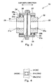
- Fig. 3 is a cross-sectional view showing the constant velocity ball joint 15 of the steering bogie 3 of Fig. 2 .
- Fig. 4 is a major component plan view for explaining groove portions 31b and 36a (32b and 37a) of the constant velocity ball joint 15 of Fig. 3 .
- the constant velocity ball joint 15 includes a first inner tube 31 and a second inner tube 32.
- the first inner tube 31 includes an insertion hole 31a to which the output shaft 28 of the electric motor 12 is splined.
- the second inner tube 32 includes an insertion hole 32a to which the input shaft 29 of the reducer 13 is splined.
- the first inner tube 31 and the second inner tube 32 are spaced apart from each other.
- a plurality of groove portions 31b extending in an axial direction of the output shaft 28 are formed on an outer peripheral surface of the inner tube 31 at equal intervals in the circumferential direction.
- a plurality of groove portions 32b extending in an axial direction of the input shaft 29 are formed on an outer peripheral surface of the inner tube 32 at equal intervals in the circumferential direction.
- a first outer tube 36 is provided at a radially outer side of the first inner tube 31, and a second outer tube 37 is provided at a radially outer side of the second inner tube 32.
- the first outer tube 36 and the second outer tube 37 are coupled to each other via a partition plate 33.
- a plurality of groove portions 36a extending in the axial direction of the output shaft 28 are formed on an inner peripheral surface of the outer tube 36 at equal intervals in the circumferential direction.
- a plurality of groove portions 37a extending in the axial direction of the input shaft 29 are formed on an inner peripheral surface of the outer tube 37 at equal intervals in the circumferential direction.
- Each of balls 34 is slidably sandwiched between the groove portion 31b of the inner tube 31 and the groove portion 36a of the outer tube 36.
- Each of balls 35 is slidably sandwiched between the groove portion 32b of the inner tube 32 and the groove portion 37a of the outer tube 37.
- An annular ball retainer 38 locked with the inner tube 31 is arranged between the inner tube 31 and the outer tube 36
- an annular ball retainer 39 locked with the inner tube 32 is arranged between the inner tube 32 and the outer tube 37.
- a plurality of ball holes each of which slidably holds the ball 34 are formed on the ball retainer 38 at equal intervals in the circumferential direction.
- a plurality of ball holes each of which slidably holds the ball 35 are formed on the ball retainer 39 at equal intervals in the circumferential direction.
- the groove portions 31b of the inner tube 31 and the groove portions 36a of the outer tube 36 extend in a direction along the axial direction of the output shaft 28, and the groove portions 32b of the inner tube 32 and the groove portions 37a of the outer tube 37 extend in a direction along the axial direction of the input shaft 29.
- Fig. 5 is a schematic plan view showing a state where the railcar 1 including the parallel cardan driving system steering bogie 3 of Fig. 1 passes through the curved line.
- a track line 100 is a curved line that indicates a center line extending between a pair of rails (not shown).
- the steering mechanism 30 (see Figs. 1 and 2 ) operates by lateral force applied from the rails to the wheels 8 of the bogie 3.
- self-steering is performed such that each of the axles 9 faces in a direction substantially perpendicular to the track line 100.
- a steering angle ⁇ s is represented by Formula 1 below where a half of a distance between the axles of the bogie 3 is denoted by L, a curvature radius of the track line 100 is denoted by R, and a steering additional coefficient is denoted by ⁇ .
- ⁇ s ⁇ • arcsin L R
- Fig. 6 is an enlarged view showing major components of the parallel cardan driving system steering bogie 3 of Fig. 2 .
- the electric motor 12 is arranged on a virtual line SL extending in the car longitudinal direction through a steering center O of the axle 9.
- the electric motor 12 includes a casing 27 which accommodates a rotor and a stator.
- the casing 27 includes an intermediate portion 27a and an outside portion 27b.
- the intermediate portion 27a is located at a car width direction intermediate region.
- the outside portion 27b is located at a car width direction outside region relative to the intermediate portion 27a.
- the outside portion 27b is provided further away from the virtual line SL than the intermediate portion 27a in the car width direction.
- a surface 27ba of the outside portion 27b is provided further away from the axle 9 than a surface 27aa of the intermediate portion 27a, the surfaces 27ba and 27aa being close to the axle 9.
- the surface 27ba of the outside portion 27b is inclined such that a distance from the surface 27ba to the axle 9 in the car longitudinal direction increases toward an outer side in the car width direction.
- the surface 27ba of the outside portion 27b has a tapered shape but may have a circular-arc shape.
- the casing 27 shown in Fig. 6 has a substantially symmetrical shape in the car width direction but does not have to be symmetrical.
- a car width direction outside portion of the axle 9 may move close to the electric motor 12.
- the casing 27 of the electric motor 12 has the above shape. Therefore, in a state where a gap is secured between the surface 27ba of the outside portion 27b of the casing 27 and the axle 9, the axle 9 can intersect with a virtual extended line VL in a plan view, the virtual extended line VL extending in the car width direction from the surface 27aa of the intermediate portion 27a.
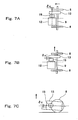
- Fig. 7A is a schematic diagram for explaining a car longitudinal direction displacement between the electric motor 12 and the reducer 13 by the axle box suspension 17.
- Fig. 7B is a schematic diagram for explaining a car width direction displacement between the electric motor 12 and the reducer 13 by the axle box suspension 17.
- Fig. 7C is a schematic diagram for explaining a vertical direction displacement between the electric motor 12 and the reducer 13 by the axle box suspension 17.
- the axle box suspension 17 (see Fig. 1 ) of the bogie 3 has flexibility in the upward/downward, forward/rearward, and leftward/rightward directions. Therefore, each of the relative displacement generated by the axle box suspension 17 in the forward/rearward direction ( Fig.
- the relative displacement generated by the axle box suspension 17 in the leftward/rightward direction ( Fig. 7B ), and the relative displacement generated by the axle box suspension 17 in the upward/downward direction ( Fig. 7C ) may occur between the electric motor 12 attached to the bogie frame 7 and the reducer 13 attached to the axle 9.
- a forward/rearward direction allowable displacement amount between the electric motor 12 and the reducer 13 in the bogie 3 by the axle box suspension 17 is denoted by ⁇ x .
- a car width direction allowable displacement amount between the electric motor 12 and the reducer 13 in the bogie 3 by the axle box suspension 17 is denoted by ⁇ y .
- an upward/downward direction allowable displacement amount between the electric motor 12 and the reducer 13 in the bogie 3 by the axle box suspension 17 is denoted by ⁇ z .
- Each of the allowable displacement amounts ⁇ x , ⁇ y , and ⁇ z denotes an upper limit of a relative displacement amount between the electric motor 12 and the reducer 13 based on a neutral state where: an axis of the output shaft 28 (see Fig. 2 ) of the electric motor 12 and an axis of the input shaft 29 (see Fig. 2 ) of the reducer 13 coincide with each other; and a center of each axle 9 coincides with a center of the bogie frame 7 (see Fig. 2 ) in the leftward/rightward direction.
- the values of the allowable displacement amounts ⁇ x , ⁇ y , and ⁇ z depend on structures of the bogie 3 including the axle box suspension 17, and the like.
- Fig. 8A is a schematic diagram showing a positional relation between the electric motor 12 and the reducer 13 in the non-steering state.
- Fig. 8B is a schematic diagram showing a state where the axle 9 is steered in one direction by the steering mechanism 30.
- Fig. 8C is a schematic diagram showing a state where the axle 9 is steered in the other direction by the steering mechanism 30.
- the steering bogie 3 is provided with the steering mechanism 30 which can rotate the axle 9 in the yawing direction. Therefore, the forward/rearward direction relative displacement and the leftward/rightward direction relative displacement ( Figs. 8B and 8C ) by the steering mechanism 30 may be generated between the electric motor 12 attached to the bogie frame 7 and the reducer 13 attached to the axle 9.
- Fig. 8A shows the positional relation between the electric motor 12 and the reducer 13 in the non-steering state.
- a center of the constant velocity ball joint 15 in the non-steering state is denoted by B (x, y).
- the non-steering state is a state where: the axles 9 are parallel to the cross beam 7a; and the front axle 9 and the rear axle 9 are parallel to each other.
- the center of the constant velocity ball joint 15 when the axle 9 is steered in one direction by the steering mechanism 30 see Fig. 1 ) as shown in Fig.
- the steering angle ⁇ s in Formula 2 denotes an allowable steering angle that is an upper limit of the steering angle.
- the value of the steering angle ⁇ s depends on the structures of the bogie 3 including the steering mechanism 30, a maximum curvature of the track, and the like.
- ⁇ sx The forward/rearward direction allowable displacement amount between the electric motor 12 and the reducer 13 by the steering mechanism 30
- ⁇ sy the leftward/rightward direction allowable displacement amount between the electric motor 12 and the reducer 13 by the steering mechanism 30
- the allowable displacement amounts ⁇ sx and ⁇ sy are represented by Formulas 4 and 5 below.
- an allowable deviation amount ⁇ r of the constant velocity ball joint 15 in a direction perpendicular to the axial direction of the output shaft 28 (see Fig. 2 ) of the electric motor 12 is set so as to satisfy Formula 6 below.
- ⁇ ⁇ r ⁇ z 2 + ⁇ x + ⁇ sx 2
- an allowable deviation amount ⁇ a of the constant velocity ball joint 15 in the axial direction of the output shaft 28 of the electric motor 12 is set so as to satisfy Formula 7.
- ⁇ ⁇ a ⁇ ⁇ y + ⁇ ⁇ sy
- the allowable deviation amount ⁇ r of the constant velocity ball joint 15 in the direction perpendicular to the axial direction of the output shaft 28 of the electric motor 12 is set to a value which is not less than 17 mm and not more than 20 mm
- the allowable deviation amount ⁇ a of the constant velocity ball joint 15 in the axial direction of the output shaft 28 of the electric motor 12 is set to a value which is not less than 15 mm and not more than 17 mm.
- the constant velocity ball joint 15 is used as a joint between the output shaft 28 of the electric motor 12 and the input shaft 29 of the reducer 13. Therefore, the backlash is unnecessary unlike the conventional WN gear coupling, and large deviation is allowable by spherical guide of the balls 34.
- the constant velocity ball joint 15 can follow the displacement. Since the constant velocity ball joint 15 can follow the steering of the axle 9, both the front axle 9 and the rear axle 9 can be configured as the driving shafts which can be steered. As a result, it is possible to provide the parallel cardan driving system steering bogie 3 capable of suppressing the change in the steering function by the running direction and the increase in the cost of the railcar 1.
- Extending directions of the groove portions 36a and 37a of the outer tubes 36 and 37 of the constant velocity ball joint 15 and extending directions of the groove portions 31b and 32b of the inner tubes 31 and 32 of the constant velocity ball joint 15 do not intersect with each other but are the same as each other. Therefore, when the balls 34 and 35 guide the groove portion 31b, 32b, 36a, and 37a to deviate the joint 15, structural resistance between the ball (34 or 35) and the groove portion (31b, 32b, 36a, or 37a) is reduced. Even when the bogie 3 passes through the sharp curved line, the constant velocity ball joint 15 largely deviates, and therefore, the steering is smoothly performed.
- the allowable deviation amounts ⁇ r and ⁇ a of the constant velocity ball joint 15 are set so as to satisfy Formulas 6 and 7, respectively, and each of the allowable deviation amounts ⁇ r and ⁇ a is larger than the allowable displacement amount between the electric motor 12 and the reducer 13 by the axle box suspension 17 and the steering mechanism 30. Therefore, the parallel cardan driving system driving bogie which can perform stable steering running can be realized.
- the allowable deviation amount ⁇ r of the constant velocity ball joint 15 in the direction perpendicular to the axial direction of the output shaft 28 is set to a value which is not less than 17 mm and not more than 20 mm
- the allowable deviation amount ⁇ a of the constant velocity ball joint 15 in the axial direction of the output shaft 28 is set to be a value which is not less than 15 mm and not more than 17 mm. Therefore, the constant velocity ball joint 15 allows the deviation which is about 1.5 times the deviation allowed by the conventional WN gear coupling.
- the parallel cardan driving system driving bogie which can perform stable steering running can be realized.
- the steering mechanism 30 is configured to steer the axle 9 such that in a plan view, the axle 9 can intersect with the virtual extended line VL extending in the car width direction from the surface 27aa of the intermediate portion 27a of the casing 27 of the electric motor 12, the surface 27aa being close to the axle 9. Therefore, while preventing the interference between the axle 9 and the electric motor 12 by the steering, devices mounted on the bogie 3 can be efficiently arranged.
- the parallel cardan driving system steering bogie according to the present invention has the above-described excellent effects. It is useful to widely apply the present invention to railcar bogies which can achieve the significance of these effects.
Landscapes
- Engineering & Computer Science (AREA)
- Mechanical Engineering (AREA)
- General Engineering & Computer Science (AREA)
- Chemical & Material Sciences (AREA)
- Combustion & Propulsion (AREA)
- Transportation (AREA)
- Arrangement Or Mounting Of Propulsion Units For Vehicles (AREA)
- Power Steering Mechanism (AREA)
- Steering Control In Accordance With Driving Conditions (AREA)
- Platform Screen Doors And Railroad Systems (AREA)
Abstract
Description
- The present invention relates to a parallel cardan driving system steering bogie for a railcar.
- Regarding a bogie of a railcar, conventionally proposed is a steering bogie configured such that an angle of an axle in a yawing direction is changed along a curved track (see
PTLs 1 to 4, for example). According to this, lateral force (turning resistance force) acting on wheels when the bogie passes through a curved line is reduced. Therefore, running stability of the bogie when the bogie passes through a sharp curved line improves. In addition, fricative sounds generated between the wheel and a railway track are reduced, and wear of the wheels and the like can also be reduced. - However, if a parallel cardan driving system driving bogie is provided with a steering mechanism, the axle steered when the bogie turns is largely displaced in the yawing direction, and this exceeds an allowable deviation of a WN gear coupling connecting a reducer and an electric motor. The WN gear coupling allows the deviation by a backlash formed between an internal tooth of an outer tube and an external tooth of an inner tube. However, since proper meshing between the internal tooth and the external tooth needs to be maintained, increasing the backlash has a limit. Therefore, a parallel cardan driving system driving bogie having a steering function does not exist currently.
- Here, PTL 5 proposes a steering bogie configured such that: one of axles is a driving shaft; the other axle is a driven shaft; and only the driven shaft has the steering function. According to this, only the driven shaft which does not require an electric motor, a joint, or a reducer is steered, it is unnecessary to consider the limit of the deviation of the joint by the steering.
-
- PTL 1:
Japanese Laid-Open Patent Application Publication No. 6-135330 - PTL 2:
Japanese Laid-Open Patent Application Publication No. 10-203364 - PTL 3: International Publication No. 2009/038068
- PTL 4:
Japanese Laid-Open Patent Application Publication No. 2010-167835 - PTL 5:
Japanese Laid-Open Patent Application Publication No. 2010-58650 - However, since only one of front and rear axles is steered, an effect of reducing the lateral force acting on the wheels changes by a running direction. Further, the driving bogie including a pair of axles is provided with only one driving shaft. Therefore, in a train in which a plurality of cars are coupled to one another, the number of cars (driving cars) each of which requires the driving bogie increases, and the number of cars (non-driving cars) each of which does not include devices (a voltage transformer, a converter, a power cable, and the like) for driving decreases. This causes an increase in cost and the like.
- An object of the present invention is to realize a parallel cardan driving system driving bogie having a steering function while suppressing a change in the steering function by a running direction and an increase in cost of a railcar.
- A parallel cardan driving system steering bogie for a railcar according to the present invention includes: a bogie frame supporting a carbody of a railcar; first and second axles arranged at front and rear sides in a car longitudinal direction, respectively, and extending along a car width direction; a steering mechanism configured to rotate both the first and second axles relative to the bogie frame to perform steering; first and second electric motors supported by the bogie frame, arranged at the front and rear sides in the car longitudinal direction, respectively, and including first and second output shafts, respectively, the first and second output shafts being parallel to the first and second axles at the time of non-steering; first and second reducers connected to the first and second axles, respectively; and a first constant velocity ball joint by which the first output shaft is coupled to the first reducer and which follows rotations of the first axle at the time of steering to allow relative displacement between the first output shaft and the first reducer, and a second constant velocity ball joint by which the second output shaft is coupled to the second reducer and which follows rotations of the second axle at the time of the steering to allow relative displacement between the second output shaft and the second reducer.
- According to the above configuration, the constant velocity ball joint is used as a joint between the output shaft and the reducer. Therefore, the backlash is unnecessary unlike the conventional WN gear coupling, and large deviation is allowable by spherical guide of the ball. On this account, even if the relative displacement of the axle in the yawing direction relative to the electric motor supported by the bogie frame occurs when the bogie passes through the curved line and the axle is steered, the constant velocity ball joint can follow the displacement. Since the constant velocity ball joint can follow the steering of the axle, both the first and second axles can be configured as the driving shafts which can be steered. As a result, it is possible to provide the parallel cardan driving system steering bogie capable of suppressing the change in the steering function by the running direction and the increase in the cost of the railcar.
- As is clear from the above explanation, the present invention can provide the parallel cardan driving system steering bogie capable of suppressing the change in the steering function by the running direction and the increase in the cost of the railcar.
-
-
Fig. 1 is a side view showing a parallel cardan driving system steering bogie according to an embodiment. -
Fig. 2 is a plan view showing the parallel cardan driving system steering bogie ofFig. 1 . -
Fig. 3 is a cross-sectional view showing a constant velocity ball joint of the steering bogie ofFig. 2 . -
Fig. 4 is a major component plan view for explaining a groove portion of the constant velocity ball joint ofFig. 3 . -
Fig. 5 is a schematic plan view showing a state where a railcar including the parallel cardan driving system steering bogies ofFig. 1 passes through a curved line. -
Fig. 6 is an enlarged view showing major components of the parallel cardan driving system steering bogie ofFig. 2 . -
Fig. 7A is a schematic diagram for explaining a car longitudinal direction displacement between an electric motor and a reducer by a suspension.Fig. 7B is a schematic diagram for explaining a car width direction displacement between the electric motor and the reducer by the suspension.Fig. 7C is a schematic diagram for explaining a vertical direction displacement between the electric motor and the reducer by the suspension. -
Fig. 8A is a schematic diagram showing a positional relation between the electric motor and the reducer in a non-steering state.Fig. 8B is a schematic diagram showing a state where an axle is steered in one direction by a steering mechanism.Fig. 8C is a schematic - Hereinafter, an embodiment will be explained in reference to the drawings.
-
Fig. 1 is a side view showing a parallel cardan drivingsystem steering bogie 3 according to the embodiment.Fig. 2 is a plan view showing the parallel cardan drivingsystem steering bogie 3 ofFig. 1 . In the following explanation, a direction in which arailcar 1 travels, that is, a length direction in which acarbody 2 extends is defined as a car longitudinal direction. A lateral direction perpendicular to the car longitudinal direction is defined as a car width direction (in the present embodiment, the car longitudinal direction is also called a "forward/rearward direction", and the car width direction is also called a "leftward/rightward direction"). In the drawings, the same reference signs are used for the same components. - As shown in
Figs. 1 and 2 , thebogie 3 of the present embodiment is a bogie which supports thecarbody 2 of therailcar 1 from below. In a plan view, thebogie 3 is formed in a point symmetry when viewed from a center of the bogie. Thebogie 3 includes abolster 5 which supports thecarbody 2 viaair springs 4 and extends in the car width direction. Thebolster 5 is connected tobolster anchors 16 bybrackets 2a of thecarbody 2. The bolster 5 is connected to abogie frame 7 through a turning guide mechanism 6 (for example, a center pin and a center plate) arranged at the center of the bogie in a plan view. To be specific, thebogie frame 7 slidably supports the bolster 5 from below so as to be able to horizontally turn relative to the bolster 5. - The
bogie frame 7 includes across beam 7a and a pair ofside sills 7b. Thecross beam 7a is located under the bolster 5 and extends in the car width direction. Theside sills 7b are connected to both respective car width direction end portions of thecross beam 7a and extend in the car longitudinal direction. Thebogie frame 7 has an H shape in a plan view. First andsecond axles 9 extending in the car width direction are arranged in front of and behind thecross beam 7a, respectively.Wheels 8 are provided at respective left and right sides of eachaxle 9. Each ofbearings 10 is provided at a car width direction end portion of theaxle 9 so as to be located outside thewheel 8 in the car width direction. Thebearings 10 rotatably support theaxles 9. Thebearings 10 are accommodated inrespective axle boxes 11. Each of theaxle boxes 11 is elastically coupled to and suspended from theside sill 7b by an axle box suspension 17 (suspension) including a coil spring (axle spring). Various types such as a publicly known axle beam type may be used as theaxle box suspension 17. - First and second
electric motors 12 are arranged in front of and behind thecross beam 7a, respectively. Each of the first and secondelectric motors 12 is not attached to theaxle 9 but is fixed to thebogie frame 7 so as to be spaced apart from theaxle 9. First andsecond reducers 13 are connected to the first andsecond axles 9, respectively. In a side view, the first andsecond reducers 13 are rotatable around the first andsecond axles 9, respectively. An end portion of thereducer 13 is elastically coupled to thecross beam 7a by asupport mechanism 14, the end portion being located at thecross beam 7a side. To be specific, the first andsecond reducers 13 may be displaced relative to thebogie frame 7 in upward/downward, forward/rearward, and leftward/rightward directions. - An
output shaft 28 of the firstelectric motor 12 is connected to aninput shaft 29 of thefirst reducer 13 through a constant velocity ball joint 15, and anoutput shaft 28 of the secondelectric motor 12 is connected to aninput shaft 29 of thesecond reducer 13 via a constant velocity ball joint 15. Theoutput shaft 28 of the firstelectric motor 12 and theinput shaft 29 of thefirst reducer 13 extend in parallel with thefirst axle 9 in the car width direction when a below-describedsteering mechanism 30 is in a non-steering state. Theoutput shaft 28 of the secondelectric motor 12 and theinput shaft 29 of thesecond reducer 13 extend in parallel with thesecond axle 9 in the car width direction when thesteering mechanism 30 is in the non-steering state. Theelectric motor 12 and thereducer 13 are lined up in the car width direction so as to overlap each other in a side view. To be specific, thebogie 3 of the present embodiment is a so-called parallel cardan driving system driving bogie. - The
bogie 3 is provided with thesteering mechanism 30. Thesteering mechanism 30 rotates both the first andsecond axles 9 relative to thebogie frame 7 in the yawing direction to perform the steering. Thesteering mechanism 30 includes swinginglevers 18. The swinging levers 18 are arranged at respective car width direction outer sides of thecross beam 7a so as to extend in a vertical direction. An upper portion of the swinginglever 18 is attached to the bolster 5 or the bolsteranchor 16 through alink 19a so as to be rotatable around afulcrum 19. A portion of the swinginglever 18 is attached to a side surface of thebogie frame 7 so as to be rotatable around afulcrum 20, the portion being located under thefulcrum 19. A portion of the swinginglever 18 is attached to one end portion of acoupling rod 24 so as to be rotatable around afulcrum 21, the portion being located between thefulcrums coupling rod 24 is rotatably coupled to theaxle box 11 located at one car longitudinal direction side. - A portion of the swinging
lever 18 is attached to one end portion of acoupling rod 25 so as to be rotatable around afulcrum 22, the portion being located under thefulcrum 20. The other end portion of thecoupling rod 25 is rotatably coupled to theaxle box 11 located at the other car longitudinal direction side. Each of thefulcrums 19 to 22 is constituted by a connector (such as a pin) by which two members are rotatably connected to each other. With this, when thebogie 3 passes through the curved line, the swinginglever 18 swings around thefulcrum 19 in a vertical plane, and therefore, both the front andrear axles 9 can be steered. At the time of the steering, the constant velocity ball joint 15 deviates and flexibly follows the rotation of theaxle 9. With this, the relative displacement between theoutput shaft 28 of theelectric motor 12 and theinput shaft 29 of thereducer 13 is allowed. -
Fig. 3 is a cross-sectional view showing the constant velocity ball joint 15 of thesteering bogie 3 ofFig. 2 .Fig. 4 is a major component plan view for explaininggroove portions Fig. 3 . As shown inFigs. 3 and 4 , the constant velocity ball joint 15 includes a firstinner tube 31 and a secondinner tube 32. The firstinner tube 31 includes aninsertion hole 31a to which theoutput shaft 28 of theelectric motor 12 is splined. The secondinner tube 32 includes aninsertion hole 32a to which theinput shaft 29 of thereducer 13 is splined. The firstinner tube 31 and the secondinner tube 32 are spaced apart from each other. A plurality ofgroove portions 31b extending in an axial direction of theoutput shaft 28 are formed on an outer peripheral surface of theinner tube 31 at equal intervals in the circumferential direction. A plurality ofgroove portions 32b extending in an axial direction of theinput shaft 29 are formed on an outer peripheral surface of theinner tube 32 at equal intervals in the circumferential direction. - A first
outer tube 36 is provided at a radially outer side of the firstinner tube 31, and a secondouter tube 37 is provided at a radially outer side of the secondinner tube 32. The firstouter tube 36 and the secondouter tube 37 are coupled to each other via apartition plate 33. A plurality ofgroove portions 36a extending in the axial direction of theoutput shaft 28 are formed on an inner peripheral surface of theouter tube 36 at equal intervals in the circumferential direction. A plurality ofgroove portions 37a extending in the axial direction of theinput shaft 29 are formed on an inner peripheral surface of theouter tube 37 at equal intervals in the circumferential direction. Each ofballs 34 is slidably sandwiched between thegroove portion 31b of theinner tube 31 and thegroove portion 36a of theouter tube 36. Each ofballs 35 is slidably sandwiched between thegroove portion 32b of theinner tube 32 and thegroove portion 37a of theouter tube 37. Anannular ball retainer 38 locked with theinner tube 31 is arranged between theinner tube 31 and theouter tube 36, and anannular ball retainer 39 locked with theinner tube 32 is arranged between theinner tube 32 and theouter tube 37. A plurality of ball holes each of which slidably holds theball 34 are formed on theball retainer 38 at equal intervals in the circumferential direction. A plurality of ball holes each of which slidably holds theball 35 are formed on theball retainer 39 at equal intervals in the circumferential direction. Thegroove portions 31b of theinner tube 31 and thegroove portions 36a of theouter tube 36 extend in a direction along the axial direction of theoutput shaft 28, and thegroove portions 32b of theinner tube 32 and thegroove portions 37a of theouter tube 37 extend in a direction along the axial direction of theinput shaft 29. -
Fig. 5 is a schematic plan view showing a state where therailcar 1 including the parallel cardan drivingsystem steering bogie 3 ofFig. 1 passes through the curved line. InFig. 5 , atrack line 100 is a curved line that indicates a center line extending between a pair of rails (not shown). When therailcar 1 passes through the curved line, the steering mechanism 30 (seeFigs. 1 and 2 ) operates by lateral force applied from the rails to thewheels 8 of thebogie 3. Thus, self-steering is performed such that each of theaxles 9 faces in a direction substantially perpendicular to thetrack line 100. A steering angle θs is represented byFormula 1 below where a half of a distance between the axles of thebogie 3 is denoted by L, a curvature radius of thetrack line 100 is denoted by R, and a steering additional coefficient is denoted by λ.
-
Fig. 6 is an enlarged view showing major components of the parallel cardan drivingsystem steering bogie 3 ofFig. 2 . As shown inFig. 6 , theelectric motor 12 is arranged on a virtual line SL extending in the car longitudinal direction through a steering center O of theaxle 9. Theelectric motor 12 includes acasing 27 which accommodates a rotor and a stator. Thecasing 27 includes anintermediate portion 27a and anoutside portion 27b. Theintermediate portion 27a is located at a car width direction intermediate region. Theoutside portion 27b is located at a car width direction outside region relative to theintermediate portion 27a. To be specific, theoutside portion 27b is provided further away from the virtual line SL than theintermediate portion 27a in the car width direction. - A surface 27ba of the
outside portion 27b is provided further away from theaxle 9 than a surface 27aa of theintermediate portion 27a, the surfaces 27ba and 27aa being close to theaxle 9. Specifically, the surface 27ba of theoutside portion 27b is inclined such that a distance from the surface 27ba to theaxle 9 in the car longitudinal direction increases toward an outer side in the car width direction. In the present embodiment, the surface 27ba of theoutside portion 27b has a tapered shape but may have a circular-arc shape. Thecasing 27 shown inFig. 6 has a substantially symmetrical shape in the car width direction but does not have to be symmetrical. - As shown by broken lines in
Fig. 6 , when theaxle 9 is steered by the steering mechanism 30 (seeFigs. 1 and 2 ), a car width direction outside portion of theaxle 9 may move close to theelectric motor 12. As described above, thecasing 27 of theelectric motor 12 has the above shape. Therefore, in a state where a gap is secured between the surface 27ba of theoutside portion 27b of thecasing 27 and theaxle 9, theaxle 9 can intersect with a virtual extended line VL in a plan view, the virtual extended line VL extending in the car width direction from the surface 27aa of theintermediate portion 27a. -
Fig. 7A is a schematic diagram for explaining a car longitudinal direction displacement between theelectric motor 12 and thereducer 13 by theaxle box suspension 17.Fig. 7B is a schematic diagram for explaining a car width direction displacement between theelectric motor 12 and thereducer 13 by theaxle box suspension 17.Fig. 7C is a schematic diagram for explaining a vertical direction displacement between theelectric motor 12 and thereducer 13 by theaxle box suspension 17. The axle box suspension 17 (seeFig. 1 ) of thebogie 3 has flexibility in the upward/downward, forward/rearward, and leftward/rightward directions. Therefore, each of the relative displacement generated by theaxle box suspension 17 in the forward/rearward direction (Fig. 7A ), the relative displacement generated by theaxle box suspension 17 in the leftward/rightward direction (Fig. 7B ), and the relative displacement generated by theaxle box suspension 17 in the upward/downward direction (Fig. 7C ) may occur between theelectric motor 12 attached to thebogie frame 7 and thereducer 13 attached to theaxle 9. - As shown in
Fig. 7A , a forward/rearward direction allowable displacement amount between theelectric motor 12 and thereducer 13 in thebogie 3 by theaxle box suspension 17 is denoted by δx. As shown inFig. 7B , a car width direction allowable displacement amount between theelectric motor 12 and thereducer 13 in thebogie 3 by theaxle box suspension 17 is denoted by δy. As shown inFig. 7C , an upward/downward direction allowable displacement amount between theelectric motor 12 and thereducer 13 in thebogie 3 by theaxle box suspension 17 is denoted by δz. Each of the allowable displacement amounts δx, δy, and δz denotes an upper limit of a relative displacement amount between theelectric motor 12 and thereducer 13 based on a neutral state where: an axis of the output shaft 28 (seeFig. 2 ) of theelectric motor 12 and an axis of the input shaft 29 (seeFig. 2 ) of thereducer 13 coincide with each other; and a center of eachaxle 9 coincides with a center of the bogie frame 7 (seeFig. 2 ) in the leftward/rightward direction. The values of the allowable displacement amounts δx, δy, and δz depend on structures of thebogie 3 including theaxle box suspension 17, and the like. -
Fig. 8A is a schematic diagram showing a positional relation between theelectric motor 12 and thereducer 13 in the non-steering state.Fig. 8B is a schematic diagram showing a state where theaxle 9 is steered in one direction by thesteering mechanism 30.Fig. 8C is a schematic diagram showing a state where theaxle 9 is steered in the other direction by thesteering mechanism 30. The steeringbogie 3 is provided with thesteering mechanism 30 which can rotate theaxle 9 in the yawing direction. Therefore, the forward/rearward direction relative displacement and the leftward/rightward direction relative displacement (Figs. 8B and 8C ) by thesteering mechanism 30 may be generated between theelectric motor 12 attached to thebogie frame 7 and thereducer 13 attached to theaxle 9. -
Fig. 8A shows the positional relation between theelectric motor 12 and thereducer 13 in the non-steering state. In a planar coordinate system in which a steering center point O (0, 0) is a base point in a plan view, a center of the constant velocity ball joint 15 in the non-steering state is denoted by B (x, y). It should be noted that the non-steering state is a state where: theaxles 9 are parallel to thecross beam 7a; and thefront axle 9 and therear axle 9 are parallel to each other. The center of the constant velocity ball joint 15 when theaxle 9 is steered in one direction by the steering mechanism 30 (seeFig. 1 ) as shown inFig. 8B is denoted by B1 (x1, y1), and the center of the constant velocity ball joint 15 when theaxle 9 is steered in the other direction by the steering mechanism 30 (seeFig. 1 ) as shown inFig. 8C is denoted by B2 (x2, y2). Those values x1, y1, x2, and y2 are represented byFormulas Formula 2 denotes an allowable steering angle that is an upper limit of the steering angle. The value of the steering angle θs depends on the structures of thebogie 3 including thesteering mechanism 30, a maximum curvature of the track, and the like.

- The forward/rearward direction allowable displacement amount between the
electric motor 12 and thereducer 13 by thesteering mechanism 30 is denoted by δsx, and the leftward/rightward direction allowable displacement amount between theelectric motor 12 and thereducer 13 by thesteering mechanism 30 is denoted by δsy. The allowable displacement amounts δsx and δsy are represented byFormulas 

- According to the above configuration, in the
steering bogie 3 of the present embodiment, an allowable deviation amount δr of the constant velocity ball joint 15 in a direction perpendicular to the axial direction of the output shaft 28 (seeFig. 2 ) of theelectric motor 12 is set so as to satisfyFormula 6 below.
- In the
steering bogie 3 of the present embodiment, an allowable deviation amount δa of the constant velocity ball joint 15 in the axial direction of theoutput shaft 28 of theelectric motor 12 is set so as to satisfyFormula 7.
- Specifically, the allowable deviation amount δr of the constant velocity ball joint 15 in the direction perpendicular to the axial direction of the
output shaft 28 of theelectric motor 12 is set to a value which is not less than 17 mm and not more than 20 mm, and the allowable deviation amount δa of the constant velocity ball joint 15 in the axial direction of theoutput shaft 28 of theelectric motor 12 is set to a value which is not less than 15 mm and not more than 17 mm. - According to the configuration explained above, the constant velocity ball joint 15 is used as a joint between the
output shaft 28 of theelectric motor 12 and theinput shaft 29 of thereducer 13. Therefore, the backlash is unnecessary unlike the conventional WN gear coupling, and large deviation is allowable by spherical guide of theballs 34. On this account, even if the relative displacement of theaxle 9 in the yawing direction relative to theelectric motor 12 supported by thebogie frame 7 occurs when thebogie 3 passes through the curved line and theaxle 9 is steered, the constant velocity ball joint 15 can follow the displacement. Since the constant velocity ball joint 15 can follow the steering of theaxle 9, both thefront axle 9 and therear axle 9 can be configured as the driving shafts which can be steered. As a result, it is possible to provide the parallel cardan drivingsystem steering bogie 3 capable of suppressing the change in the steering function by the running direction and the increase in the cost of therailcar 1. - Extending directions of the
groove portions outer tubes groove portions inner tubes balls groove portion bogie 3 passes through the sharp curved line, the constant velocity ball joint 15 largely deviates, and therefore, the steering is smoothly performed. - The allowable deviation amounts δr and δa of the constant velocity ball joint 15 are set so as to satisfy
Formulas electric motor 12 and thereducer 13 by theaxle box suspension 17 and thesteering mechanism 30. Therefore, the parallel cardan driving system driving bogie which can perform stable steering running can be realized. More specifically, the allowable deviation amount δr of the constant velocity ball joint 15 in the direction perpendicular to the axial direction of theoutput shaft 28 is set to a value which is not less than 17 mm and not more than 20 mm, and the allowable deviation amount δa of the constant velocity ball joint 15 in the axial direction of theoutput shaft 28 is set to be a value which is not less than 15 mm and not more than 17 mm. Therefore, the constant velocity ball joint 15 allows the deviation which is about 1.5 times the deviation allowed by the conventional WN gear coupling. Thus, the parallel cardan driving system driving bogie which can perform stable steering running can be realized. - Further, the
steering mechanism 30 is configured to steer theaxle 9 such that in a plan view, theaxle 9 can intersect with the virtual extended line VL extending in the car width direction from the surface 27aa of theintermediate portion 27a of thecasing 27 of theelectric motor 12, the surface 27aa being close to theaxle 9. Therefore, while preventing the interference between theaxle 9 and theelectric motor 12 by the steering, devices mounted on thebogie 3 can be efficiently arranged. - The present invention is not limited to the above-described embodiment, and modifications, additions, and eliminations may be made within the scope of the present invention.
- As above, the parallel cardan driving system steering bogie according to the present invention has the above-described excellent effects. It is useful to widely apply the present invention to railcar bogies which can achieve the significance of these effects.
-
- 1
- railcar
- 2
- carbody
- 3
- steering bogie
- 7
- bogie frame
- 9
- axle
- 12
- electric motor
- 13
- reducer
- 15
- constant velocity ball joint
- 17
- axle box suspension (suspension)
- 27
- casing
- 27a
- intermediate portion
- 27b
- outside portion
- 28
- output shaft
- 30
- steering mechanism
- 31, 32
- inner tube
- 34, 35
- ball
- 36, 37
- outer tube
- 38, 39
- retainer
- 31b, 32b, 36a, 37a
- groove portion
- VL
- virtual extended line
Claims (5)
- A parallel cardan driving system steering bogie for a railcar,
the parallel cardan driving system steering bogie comprising:a bogie frame supporting a carbody of a railcar;first and second axles arranged at front and rear sides in a car longitudinal direction, respectively, and extending along a car width direction;a steering mechanism configured to rotate both the first and second axles relative to the bogie frame to perform steering;first and second electric motors supported by the bogie frame, arranged at the front and rear sides in the car longitudinal direction, respectively, and including first and second output shafts, respectively, the first and second output shafts being parallel to the first and second axles at the time of non-steering;first and second reducers connected to the first and second axles, respectively; anda first constant velocity ball joint by which the first output shaft is coupled to the first reducer and which follows rotations of the first axle at the time of steering to allow relative displacement between the first output shaft and the first reducer, and a second constant velocity ball joint by which the second output shaft is coupled to the second reducer and which follows rotations of the second axle at the time of the steering to allow relative displacement between the second output shaft and the second reducer. - The parallel cardan driving system steering bogie according to claim 1, wherein:each of the first and second constant velocity ball joints includesan inner tube including an outer peripheral surface on which a groove portion extending in an axial direction is formed,an outer tube including an inner peripheral surface on which a groove portion extending in the axial direction is formed,a ball sandwiched between the groove portion of the inner tube and the groove portion of the outer tube, anda ball retainer arranged between the inner tube and the outer tube and holding the ball; anda direction in which the groove portion of the inner tube extends and a direction in which the groove portion of the outer tube extends are the same as each other.
- The parallel cardan driving system steering bogie according to claim 1 or 2, further comprising suspensions by which the first and second axles are connected to the bogie frame, wherein:when each of a vertical direction allowable displacement amount between the first reducer and the first electric motor by the suspension and a vertical direction allowable displacement amount between the second reducer and the second electric motor by the suspension is denoted by δz, each of a car longitudinal direction allowable displacement amount between the first reducer and the first electric motor by the suspension and a car longitudinal direction allowable displacement amount between the second reducer and the second electric motor by the suspension is denoted by δx, each of a car width direction allowable displacement amount between the first reducer and the first electric motor by the suspension and a car width direction allowable displacement amount between the second reducer and the second electric motor by the suspension is denoted by δy, each of a car longitudinal direction allowable displacement amount between the first reducer and the first electric motor by the steering mechanism and a car longitudinal direction allowable displacement amount between the second reducer and the second electric motor by the steering mechanism is denoted by δsx, and each of a car width direction allowable displacement amount between the first reducer and the first electric motor by the steering mechanism and a car width direction allowable displacement amount between the second reducer and the second electric motor by the steering mechanism is denoted by δsy,an allowable deviation amount δr of each of the first constant velocity ball joint in a direction perpendicular to an axial direction of the first output shaft and the second constant velocity ball joint in a direction perpendicular to an axial direction of the second output shaft is represented by δr > (δz 2 + (δx + δsx)2)1/2, andan allowable deviation amount δa of each of the first constant velocity ball joint in the axial direction of the first output shaft and the second constant velocity ball joint in the axial direction of the second output shaft is represented by δa > δy + δsy.
- The parallel cardan driving system steering bogie according to any one of claims 1 to 3, wherein:the allowable deviation amount δr of each of the first constant velocity ball joint in the direction perpendicular to the axial direction of the first output shaft and the second constant velocity ball joint in the direction perpendicular to the axial direction of the second output shaft is set to a value which is not less than 17 mm and not more than 20 mm; andthe allowable deviation amount δa of each of the first constant velocity ball joint in the axial direction of the first output shaft and the second constant velocity ball joint in the axial direction of the second output shaft is set to a value which is not less than 15 mm and not more than 17 mm.
- The parallel cardan driving system steering bogie according to any one of claims 1 to 4, wherein:the first and second electric motors include respective casings;each of the casings includesan intermediate portion located at a car width direction intermediate region and an outside portion located at a car width direction outside region relative to the intermediate portion;a surface of the outside portion is provided further away from the axle than a surface of the intermediate portion, the surfaces being close to the axle; andthe steering mechanism steers the axle such that in a plan view, the axle intersects with a virtual extended line in a state where a gap is secured between the axle and the surface of the outside portion, the surface of the outside portion being close to the axle, the virtual extended line extending in the car width direction from the surface of the intermediate portion, the surface of the intermediate portion being close to the axle.
Applications Claiming Priority (2)
| Application Number | Priority Date | Filing Date | Title |
|---|---|---|---|
| JP2013044297A JP6185727B2 (en) | 2013-03-06 | 2013-03-06 | Parallel cardan drive steering wheel |
| PCT/JP2014/001212 WO2014136449A1 (en) | 2013-03-06 | 2014-03-05 | Parallel cardan drive-type steering bogie |
Publications (3)
| Publication Number | Publication Date |
|---|---|
| EP2965966A1 true EP2965966A1 (en) | 2016-01-13 |
| EP2965966A4 EP2965966A4 (en) | 2016-12-14 |
| EP2965966B1 EP2965966B1 (en) | 2020-10-21 |
Family
ID=51490982
Family Applications (1)
| Application Number | Title | Priority Date | Filing Date |
|---|---|---|---|
| EP14761074.5A Active EP2965966B1 (en) | 2013-03-06 | 2014-03-05 | Parallel cardan driving system steering bogie |
Country Status (6)
| Country | Link |
|---|---|
| US (1) | US9902407B2 (en) |
| EP (1) | EP2965966B1 (en) |
| JP (1) | JP6185727B2 (en) |
| KR (1) | KR101733602B1 (en) |
| CN (1) | CN105008205B (en) |
| WO (1) | WO2014136449A1 (en) |
Cited By (2)
| Publication number | Priority date | Publication date | Assignee | Title |
|---|---|---|---|---|
| RU177632U1 (en) * | 2017-02-20 | 2018-03-02 | ФЕДЕРАЛЬНОЕ ГОСУДАРСТВЕННОЕ БЮДЖЕТНОЕ ОБРАЗОВАТЕЛЬНОЕ УЧРЕЖДЕНИЕ ВЫСШЕГО ОБРАЗОВАНИЯ "Брянский государственный технический университет" | Suspension of traction electric motors of a railway vehicle |
| RU189364U1 (en) * | 2017-10-30 | 2019-05-21 | ФЕДЕРАЛЬНОЕ ГОСУДАРСТВЕННОЕ БЮДЖЕТНОЕ ОБРАЗОВАТЕЛЬНОЕ УЧРЕЖДЕНИЕ ВЫСШЕГО ОБРАЗОВАНИЯ "Брянский государственный технический университет" | Traction drive locomotive |
Families Citing this family (10)
| Publication number | Priority date | Publication date | Assignee | Title |
|---|---|---|---|---|
| AU2012329458B2 (en) * | 2011-10-26 | 2016-05-12 | Nippon Steel Corporation | Method and device for steering truck of railway vehicle, and truck |
| CN102963388B (en) * | 2012-07-10 | 2015-06-24 | 南车南京浦镇车辆有限公司 | Flexible direct-drive type steering rack |
| JP6620007B2 (en) | 2015-12-18 | 2019-12-11 | 川崎重工業株式会社 | Railcar steering wheel |
| CN109780073B (en) * | 2019-03-06 | 2024-04-09 | 杭州精通汽车零部件有限公司 | Constant speed frame type universal joint fork assembly |
| RU2704653C1 (en) * | 2019-03-07 | 2019-10-30 | Федеральное государственное бюджетное образовательное учреждение высшего образования "Елецкий государственный университет им. И.А. Бунина" | Locomotive wheel-motor unit |
| WO2022083251A1 (en) * | 2020-10-20 | 2022-04-28 | 中车长江车辆有限公司 | Central suspension device, bogie, and suspended rail transit system |
| CN112406910B (en) * | 2020-10-20 | 2022-12-13 | 中车长江车辆有限公司 | Suspension type rail transit system |
| FR3116255B1 (en) * | 2020-11-13 | 2022-11-18 | Alstom Transp Tech | Railway vehicle bogie, railway vehicle and associated machining method |
| CN114701533A (en) * | 2022-04-08 | 2022-07-05 | 武汉理工大学 | Steering error calibration control method applied to multi-connecting-rod type active radial bogie |
| CN114701532A (en) * | 2022-04-08 | 2022-07-05 | 武汉理工大学 | Multi-connecting-rod steering mechanism suitable for train bogie |
Family Cites Families (28)
| Publication number | Priority date | Publication date | Assignee | Title |
|---|---|---|---|---|
| US1810834A (en) * | 1930-12-03 | 1931-06-16 | William C Klein | Roller-bearing free wheel drive |
| US2312924A (en) * | 1942-03-12 | 1943-03-02 | Gen Electric | Locomotive drive arrangement |
| US3152558A (en) * | 1962-08-23 | 1964-10-13 | Westinghouse Electric Corp | Traction power unit suspension |
| US4228739A (en) * | 1977-07-01 | 1980-10-21 | The Garrett Corporation | Motorized railway truck articulated shaft housing |
| US4660476A (en) * | 1984-03-29 | 1987-04-28 | Franz Philip M | Self-steering rail truck |
| US4648326A (en) * | 1985-02-22 | 1987-03-10 | Lukens General Industries, Inc. | Radial axle railway truck with axle couplings at sides transversely interconnected with each other |
| DE3612811A1 (en) | 1985-04-30 | 1986-11-06 | Sig Schweizerische Industrie-Gesellschaft, Neuhausen Am Rheinfall | Folding, sealing and transporting apparatus in a machine for the packaging of slabs |
| DE3725574A1 (en) * | 1987-08-01 | 1989-02-16 | Messerschmitt Boelkow Blohm | CHASSIS FOR A RAIL VEHICLE |
| FR2646134B1 (en) * | 1989-04-25 | 1993-04-30 | Alsthom Gec | BOGIE WITH TWO ADJUSTABLE AXLES, MOUNTING PIVOTABLE UNDER A BODY OF A RAIL VEHICLE |
| US5249530A (en) * | 1992-05-26 | 1993-10-05 | Westinghouse Electric Corp. | Forced steering railroad truck system with central transverse pivoted shaft |
| JP3122259B2 (en) | 1992-10-27 | 2001-01-09 | 株式会社東芝 | Truck with steering link |
| DE29506461U1 (en) * | 1995-04-15 | 1995-06-22 | Renk Tacke Gmbh, 86159 Augsburg | Double joint coupling |
| DE59507963D1 (en) | 1995-08-23 | 2000-04-13 | Schweizerische Lokomotiv | Drive for a rail vehicle with adjustable wheelsets and rail vehicle with such a drive |
| JP3448445B2 (en) | 1997-01-17 | 2003-09-22 | 財団法人鉄道総合技術研究所 | Steering device for bogies for railway vehicles |
| JP3399777B2 (en) * | 1997-04-23 | 2003-04-21 | 財団法人鉄道総合技術研究所 | Railcar bogie |
| JPH11124033A (en) * | 1997-10-23 | 1999-05-11 | Fuji Heavy Ind Ltd | Steering bogie for railway vehicles |
| JP3498258B2 (en) * | 1998-07-22 | 2004-02-16 | 日本車輌製造株式会社 | 2-axle bogie for railway vehicles |
| JP3469878B2 (en) * | 2000-02-16 | 2003-11-25 | デルファイ・テクノロジーズ・インコーポレーテッド | Constant speed stroke joint |
| JP4854944B2 (en) * | 2004-09-16 | 2012-01-18 | Ntn株式会社 | Rail vehicle shaft couplings |
| JP4979374B2 (en) * | 2006-12-28 | 2012-07-18 | 川崎重工業株式会社 | Cart for low-floor railway vehicles |
| JP2009038068A (en) | 2007-07-31 | 2009-02-19 | Nec Electronics Corp | Semiconductor device and manufacturing method thereof |
| EP3081451B1 (en) | 2007-09-21 | 2020-08-12 | Nippon Steel Corporation | Steerable truck for a railway car, a railway car, and an articulated car |
| KR100916594B1 (en) * | 2007-12-06 | 2009-09-11 | 한국철도기술연구원 | Active Steering Bogie for Railroad Vehicles by Lever Action |
| US20110130212A1 (en) * | 2008-07-28 | 2011-06-02 | Mordehai Sholev | Variable Axial-Angle Coupling |
| JP5512108B2 (en) * | 2008-09-03 | 2014-06-04 | 新日鐵住金株式会社 | Railroad vehicle steering carriage, railroad vehicle, articulated vehicle |
| JP5254058B2 (en) | 2009-01-20 | 2013-08-07 | 公益財団法人鉄道総合技術研究所 | Shaft box support device |
| CN101968084A (en) * | 2010-09-28 | 2011-02-09 | 镇江市华阳机电制造有限公司 | Roller universal coupling |
| JP5433080B2 (en) * | 2011-04-07 | 2014-03-05 | 川崎重工業株式会社 | Railcar bogie |
-
2013
- 2013-03-06 JP JP2013044297A patent/JP6185727B2/en not_active Expired - Fee Related
-
2014
- 2014-03-05 WO PCT/JP2014/001212 patent/WO2014136449A1/en not_active Ceased
- 2014-03-05 KR KR1020157026734A patent/KR101733602B1/en not_active Expired - Fee Related
- 2014-03-05 CN CN201480011952.1A patent/CN105008205B/en not_active Expired - Fee Related
- 2014-03-05 EP EP14761074.5A patent/EP2965966B1/en active Active
- 2014-03-05 US US14/773,576 patent/US9902407B2/en not_active Expired - Fee Related
Cited By (2)
| Publication number | Priority date | Publication date | Assignee | Title |
|---|---|---|---|---|
| RU177632U1 (en) * | 2017-02-20 | 2018-03-02 | ФЕДЕРАЛЬНОЕ ГОСУДАРСТВЕННОЕ БЮДЖЕТНОЕ ОБРАЗОВАТЕЛЬНОЕ УЧРЕЖДЕНИЕ ВЫСШЕГО ОБРАЗОВАНИЯ "Брянский государственный технический университет" | Suspension of traction electric motors of a railway vehicle |
| RU189364U1 (en) * | 2017-10-30 | 2019-05-21 | ФЕДЕРАЛЬНОЕ ГОСУДАРСТВЕННОЕ БЮДЖЕТНОЕ ОБРАЗОВАТЕЛЬНОЕ УЧРЕЖДЕНИЕ ВЫСШЕГО ОБРАЗОВАНИЯ "Брянский государственный технический университет" | Traction drive locomotive |
Also Published As
| Publication number | Publication date |
|---|---|
| WO2014136449A1 (en) | 2014-09-12 |
| JP2014172437A (en) | 2014-09-22 |
| US9902407B2 (en) | 2018-02-27 |
| KR101733602B1 (en) | 2017-05-10 |
| EP2965966B1 (en) | 2020-10-21 |
| EP2965966A4 (en) | 2016-12-14 |
| US20160023670A1 (en) | 2016-01-28 |
| KR20150125695A (en) | 2015-11-09 |
| CN105008205A (en) | 2015-10-28 |
| JP6185727B2 (en) | 2017-08-23 |
| CN105008205B (en) | 2018-03-13 |
Similar Documents
| Publication | Publication Date | Title |
|---|---|---|
| EP2965966B1 (en) | Parallel cardan driving system steering bogie | |
| US8171861B2 (en) | Railway vehicle power bogie having a semi-suspended motor | |
| US10167002B2 (en) | Meter gauge power bogie and meter gauge vehicle | |
| US6871598B2 (en) | Arrangement of radial bogie | |
| EP2086812B1 (en) | Active steering bogie for railway vehicles using leverage | |
| CN109835364B (en) | Bogie and have its rail transit system | |
| JPS5867558A (en) | Connecting truck assembled body | |
| JP2017171288A (en) | Bogie truck with external motor and railway vehicle cooperating with the same | |
| KR100921550B1 (en) | Active Steering Bogies for Rail Vehicles | |
| JP4687727B2 (en) | Power transmission device for work vehicle | |
| JP5512108B2 (en) | Railroad vehicle steering carriage, railroad vehicle, articulated vehicle | |
| JP5502683B2 (en) | Low-floor truck for railway vehicles | |
| CN104709294A (en) | Engine-axel coaxial railway vehicle driving wheel rotating rack | |
| JP4205433B2 (en) | Self-steering 3-axis bogie | |
| CN106573629B (en) | Railcar bogie and rail truck with the bogie | |
| JP2010058649A (en) | Triaxial steering truck for railway car, and railway car | |
| WO2018020980A1 (en) | Bogie for railroad car, and railroad car provided with bogie | |
| RU2243914C2 (en) | Group electric drive of diesel locomotive three-axle bogie | |
| JP2000016286A (en) | Power bogies for railway vehicles | |
| US11046337B2 (en) | Double axle drive | |
| JPH10217963A (en) | Drive mechanism of rail-to-rail variable bogie for railway vehicles | |
| JPS63305071A (en) | Railway vehicle trolley | |
| JPH11334587A (en) | Electric bogies for railway vehicles | |
| JPS60189668A (en) | Drive device for electric vehicle trolley | |
| JPH0371304B2 (en) |
Legal Events
| Date | Code | Title | Description |
|---|---|---|---|
| PUAI | Public reference made under article 153(3) epc to a published international application that has entered the european phase |
Free format text: ORIGINAL CODE: 0009012 |
|
| 17P | Request for examination filed |
Effective date: 20150827 |
|
| AK | Designated contracting states |
Kind code of ref document: A1 Designated state(s): AL AT BE BG CH CY CZ DE DK EE ES FI FR GB GR HR HU IE IS IT LI LT LU LV MC MK MT NL NO PL PT RO RS SE SI SK SM TR |
|
| AX | Request for extension of the european patent |
Extension state: BA ME |
|
| DAX | Request for extension of the european patent (deleted) | ||
| A4 | Supplementary search report drawn up and despatched |
Effective date: 20161115 |
|
| RIC1 | Information provided on ipc code assigned before grant |
Ipc: B61F 5/46 20060101AFI20161109BHEP Ipc: F16D 3/18 20060101ALI20161109BHEP Ipc: B61C 9/38 20060101ALI20161109BHEP |
|
| GRAP | Despatch of communication of intention to grant a patent |
Free format text: ORIGINAL CODE: EPIDOSNIGR1 |
|
| STAA | Information on the status of an ep patent application or granted ep patent |
Free format text: STATUS: GRANT OF PATENT IS INTENDED |
|
| INTG | Intention to grant announced |
Effective date: 20200528 |
|
| GRAS | Grant fee paid |
Free format text: ORIGINAL CODE: EPIDOSNIGR3 |
|
| GRAA | (expected) grant |
Free format text: ORIGINAL CODE: 0009210 |
|
| STAA | Information on the status of an ep patent application or granted ep patent |
Free format text: STATUS: THE PATENT HAS BEEN GRANTED |
|
| AK | Designated contracting states |
Kind code of ref document: B1 Designated state(s): AL AT BE BG CH CY CZ DE DK EE ES FI FR GB GR HR HU IE IS IT LI LT LU LV MC MK MT NL NO PL PT RO RS SE SI SK SM TR |
|
| REG | Reference to a national code |
Ref country code: GB Ref legal event code: FG4D |
|
| REG | Reference to a national code |
Ref country code: CH Ref legal event code: EP |
|
| REG | Reference to a national code |
Ref country code: DE Ref legal event code: R096 Ref document number: 602014071467 Country of ref document: DE |
|
| REG | Reference to a national code |
Ref country code: IE Ref legal event code: FG4D |
|
| REG | Reference to a national code |
Ref country code: AT Ref legal event code: REF Ref document number: 1325562 Country of ref document: AT Kind code of ref document: T Effective date: 20201115 |
|
| REG | Reference to a national code |
Ref country code: AT Ref legal event code: MK05 Ref document number: 1325562 Country of ref document: AT Kind code of ref document: T Effective date: 20201021 |
|
| REG | Reference to a national code |
Ref country code: NL Ref legal event code: MP Effective date: 20201021 |
|
| PG25 | Lapsed in a contracting state [announced via postgrant information from national office to epo] |
Ref country code: FI Free format text: LAPSE BECAUSE OF FAILURE TO SUBMIT A TRANSLATION OF THE DESCRIPTION OR TO PAY THE FEE WITHIN THE PRESCRIBED TIME-LIMIT Effective date: 20201021 Ref country code: RS Free format text: LAPSE BECAUSE OF FAILURE TO SUBMIT A TRANSLATION OF THE DESCRIPTION OR TO PAY THE FEE WITHIN THE PRESCRIBED TIME-LIMIT Effective date: 20201021 Ref country code: PT Free format text: LAPSE BECAUSE OF FAILURE TO SUBMIT A TRANSLATION OF THE DESCRIPTION OR TO PAY THE FEE WITHIN THE PRESCRIBED TIME-LIMIT Effective date: 20210222 Ref country code: NO Free format text: LAPSE BECAUSE OF FAILURE TO SUBMIT A TRANSLATION OF THE DESCRIPTION OR TO PAY THE FEE WITHIN THE PRESCRIBED TIME-LIMIT Effective date: 20210121 Ref country code: NL Free format text: LAPSE BECAUSE OF FAILURE TO SUBMIT A TRANSLATION OF THE DESCRIPTION OR TO PAY THE FEE WITHIN THE PRESCRIBED TIME-LIMIT Effective date: 20201021 Ref country code: GR Free format text: LAPSE BECAUSE OF FAILURE TO SUBMIT A TRANSLATION OF THE DESCRIPTION OR TO PAY THE FEE WITHIN THE PRESCRIBED TIME-LIMIT Effective date: 20210122 |
|
| REG | Reference to a national code |
Ref country code: LT Ref legal event code: MG4D |
|
| PG25 | Lapsed in a contracting state [announced via postgrant information from national office to epo] |
Ref country code: ES Free format text: LAPSE BECAUSE OF FAILURE TO SUBMIT A TRANSLATION OF THE DESCRIPTION OR TO PAY THE FEE WITHIN THE PRESCRIBED TIME-LIMIT Effective date: 20201021 Ref country code: AT Free format text: LAPSE BECAUSE OF FAILURE TO SUBMIT A TRANSLATION OF THE DESCRIPTION OR TO PAY THE FEE WITHIN THE PRESCRIBED TIME-LIMIT Effective date: 20201021 Ref country code: BG Free format text: LAPSE BECAUSE OF FAILURE TO SUBMIT A TRANSLATION OF THE DESCRIPTION OR TO PAY THE FEE WITHIN THE PRESCRIBED TIME-LIMIT Effective date: 20210121 Ref country code: LV Free format text: LAPSE BECAUSE OF FAILURE TO SUBMIT A TRANSLATION OF THE DESCRIPTION OR TO PAY THE FEE WITHIN THE PRESCRIBED TIME-LIMIT Effective date: 20201021 Ref country code: IS Free format text: LAPSE BECAUSE OF FAILURE TO SUBMIT A TRANSLATION OF THE DESCRIPTION OR TO PAY THE FEE WITHIN THE PRESCRIBED TIME-LIMIT Effective date: 20210221 Ref country code: PL Free format text: LAPSE BECAUSE OF FAILURE TO SUBMIT A TRANSLATION OF THE DESCRIPTION OR TO PAY THE FEE WITHIN THE PRESCRIBED TIME-LIMIT Effective date: 20201021 Ref country code: SE Free format text: LAPSE BECAUSE OF FAILURE TO SUBMIT A TRANSLATION OF THE DESCRIPTION OR TO PAY THE FEE WITHIN THE PRESCRIBED TIME-LIMIT Effective date: 20201021 |
|
| PG25 | Lapsed in a contracting state [announced via postgrant information from national office to epo] |
Ref country code: HR Free format text: LAPSE BECAUSE OF FAILURE TO SUBMIT A TRANSLATION OF THE DESCRIPTION OR TO PAY THE FEE WITHIN THE PRESCRIBED TIME-LIMIT Effective date: 20201021 |
|
| REG | Reference to a national code |
Ref country code: DE Ref legal event code: R097 Ref document number: 602014071467 Country of ref document: DE |
|
| PG25 | Lapsed in a contracting state [announced via postgrant information from national office to epo] |
Ref country code: RO Free format text: LAPSE BECAUSE OF FAILURE TO SUBMIT A TRANSLATION OF THE DESCRIPTION OR TO PAY THE FEE WITHIN THE PRESCRIBED TIME-LIMIT Effective date: 20201021 Ref country code: SK Free format text: LAPSE BECAUSE OF FAILURE TO SUBMIT A TRANSLATION OF THE DESCRIPTION OR TO PAY THE FEE WITHIN THE PRESCRIBED TIME-LIMIT Effective date: 20201021 Ref country code: LT Free format text: LAPSE BECAUSE OF FAILURE TO SUBMIT A TRANSLATION OF THE DESCRIPTION OR TO PAY THE FEE WITHIN THE PRESCRIBED TIME-LIMIT Effective date: 20201021 Ref country code: SM Free format text: LAPSE BECAUSE OF FAILURE TO SUBMIT A TRANSLATION OF THE DESCRIPTION OR TO PAY THE FEE WITHIN THE PRESCRIBED TIME-LIMIT Effective date: 20201021 Ref country code: CZ Free format text: LAPSE BECAUSE OF FAILURE TO SUBMIT A TRANSLATION OF THE DESCRIPTION OR TO PAY THE FEE WITHIN THE PRESCRIBED TIME-LIMIT Effective date: 20201021 Ref country code: EE Free format text: LAPSE BECAUSE OF FAILURE TO SUBMIT A TRANSLATION OF THE DESCRIPTION OR TO PAY THE FEE WITHIN THE PRESCRIBED TIME-LIMIT Effective date: 20201021 |
|
| PLBE | No opposition filed within time limit |
Free format text: ORIGINAL CODE: 0009261 |
|
| STAA | Information on the status of an ep patent application or granted ep patent |
Free format text: STATUS: NO OPPOSITION FILED WITHIN TIME LIMIT |
|
| PG25 | Lapsed in a contracting state [announced via postgrant information from national office to epo] |
Ref country code: DK Free format text: LAPSE BECAUSE OF FAILURE TO SUBMIT A TRANSLATION OF THE DESCRIPTION OR TO PAY THE FEE WITHIN THE PRESCRIBED TIME-LIMIT Effective date: 20201021 |
|
| 26N | No opposition filed |
Effective date: 20210722 |
|
| PG25 | Lapsed in a contracting state [announced via postgrant information from national office to epo] |
Ref country code: AL Free format text: LAPSE BECAUSE OF FAILURE TO SUBMIT A TRANSLATION OF THE DESCRIPTION OR TO PAY THE FEE WITHIN THE PRESCRIBED TIME-LIMIT Effective date: 20201021 Ref country code: MC Free format text: LAPSE BECAUSE OF FAILURE TO SUBMIT A TRANSLATION OF THE DESCRIPTION OR TO PAY THE FEE WITHIN THE PRESCRIBED TIME-LIMIT Effective date: 20201021 Ref country code: IT Free format text: LAPSE BECAUSE OF FAILURE TO SUBMIT A TRANSLATION OF THE DESCRIPTION OR TO PAY THE FEE WITHIN THE PRESCRIBED TIME-LIMIT Effective date: 20201021 |
|
| REG | Reference to a national code |
Ref country code: CH Ref legal event code: PL |
|
| GBPC | Gb: european patent ceased through non-payment of renewal fee |
Effective date: 20210305 |
|
| PG25 | Lapsed in a contracting state [announced via postgrant information from national office to epo] |
Ref country code: SI Free format text: LAPSE BECAUSE OF FAILURE TO SUBMIT A TRANSLATION OF THE DESCRIPTION OR TO PAY THE FEE WITHIN THE PRESCRIBED TIME-LIMIT Effective date: 20201021 |
|
| REG | Reference to a national code |
Ref country code: BE Ref legal event code: MM Effective date: 20210331 |
|
| PG25 | Lapsed in a contracting state [announced via postgrant information from national office to epo] |
Ref country code: CH Free format text: LAPSE BECAUSE OF NON-PAYMENT OF DUE FEES Effective date: 20210331 Ref country code: LI Free format text: LAPSE BECAUSE OF NON-PAYMENT OF DUE FEES Effective date: 20210331 Ref country code: LU Free format text: LAPSE BECAUSE OF NON-PAYMENT OF DUE FEES Effective date: 20210305 Ref country code: GB Free format text: LAPSE BECAUSE OF NON-PAYMENT OF DUE FEES Effective date: 20210305 Ref country code: IE Free format text: LAPSE BECAUSE OF NON-PAYMENT OF DUE FEES Effective date: 20210305 |
|
| REG | Reference to a national code |
Ref country code: DE Ref legal event code: R081 Ref document number: 602014071467 Country of ref document: DE Owner name: KAWASAKI RAILCAR MANUFACTURING CO., LTD., KOBE, JP Free format text: FORMER OWNER: KAWASAKI JUKOGYO KABUSHIKI KAISHA, KOBE-SHI, HYOGO, JP |
|
| PG25 | Lapsed in a contracting state [announced via postgrant information from national office to epo] |
Ref country code: IS Free format text: LAPSE BECAUSE OF FAILURE TO SUBMIT A TRANSLATION OF THE DESCRIPTION OR TO PAY THE FEE WITHIN THE PRESCRIBED TIME-LIMIT Effective date: 20210221 |
|
| PG25 | Lapsed in a contracting state [announced via postgrant information from national office to epo] |
Ref country code: BE Free format text: LAPSE BECAUSE OF NON-PAYMENT OF DUE FEES Effective date: 20210331 |
|
| PG25 | Lapsed in a contracting state [announced via postgrant information from national office to epo] |
Ref country code: HU Free format text: LAPSE BECAUSE OF FAILURE TO SUBMIT A TRANSLATION OF THE DESCRIPTION OR TO PAY THE FEE WITHIN THE PRESCRIBED TIME-LIMIT; INVALID AB INITIO Effective date: 20140305 |
|
| PG25 | Lapsed in a contracting state [announced via postgrant information from national office to epo] |
Ref country code: CY Free format text: LAPSE BECAUSE OF FAILURE TO SUBMIT A TRANSLATION OF THE DESCRIPTION OR TO PAY THE FEE WITHIN THE PRESCRIBED TIME-LIMIT Effective date: 20201021 |
|
| PG25 | Lapsed in a contracting state [announced via postgrant information from national office to epo] |
Ref country code: MK Free format text: LAPSE BECAUSE OF FAILURE TO SUBMIT A TRANSLATION OF THE DESCRIPTION OR TO PAY THE FEE WITHIN THE PRESCRIBED TIME-LIMIT Effective date: 20201021 |
|
| PG25 | Lapsed in a contracting state [announced via postgrant information from national office to epo] |
Ref country code: TR Free format text: LAPSE BECAUSE OF FAILURE TO SUBMIT A TRANSLATION OF THE DESCRIPTION OR TO PAY THE FEE WITHIN THE PRESCRIBED TIME-LIMIT Effective date: 20201021 |
|
| PG25 | Lapsed in a contracting state [announced via postgrant information from national office to epo] |
Ref country code: MT Free format text: LAPSE BECAUSE OF FAILURE TO SUBMIT A TRANSLATION OF THE DESCRIPTION OR TO PAY THE FEE WITHIN THE PRESCRIBED TIME-LIMIT Effective date: 20201021 |
|
| PGFP | Annual fee paid to national office [announced via postgrant information from national office to epo] |
Ref country code: DE Payment date: 20260128 Year of fee payment: 13 |
|
| PGFP | Annual fee paid to national office [announced via postgrant information from national office to epo] |
Ref country code: FR Payment date: 20260209 Year of fee payment: 13 |