EP2965930A1 - Control device for a pressurised air assembly of a commercial vehicle - Google Patents
Control device for a pressurised air assembly of a commercial vehicle Download PDFInfo
- Publication number
- EP2965930A1 EP2965930A1 EP15175995.8A EP15175995A EP2965930A1 EP 2965930 A1 EP2965930 A1 EP 2965930A1 EP 15175995 A EP15175995 A EP 15175995A EP 2965930 A1 EP2965930 A1 EP 2965930A1
- Authority
- EP
- European Patent Office
- Prior art keywords
- suspension system
- air suspension
- chassis
- cabin
- control
- Prior art date
- Legal status (The legal status is an assumption and is not a legal conclusion. Google has not performed a legal analysis and makes no representation as to the accuracy of the status listed.)
- Granted
Links
- 239000000725 suspension Substances 0.000 claims abstract description 233
- 230000033228 biological regulation Effects 0.000 claims abstract description 75
- 230000008859 change Effects 0.000 claims description 54
- 230000001105 regulatory effect Effects 0.000 claims description 20
- 230000033001 locomotion Effects 0.000 claims description 19
- 238000000034 method Methods 0.000 claims description 19
- 238000013016 damping Methods 0.000 claims description 16
- 230000001276 controlling effect Effects 0.000 claims description 15
- 238000011068 loading method Methods 0.000 claims description 13
- 230000001133 acceleration Effects 0.000 claims description 11
- 230000000694 effects Effects 0.000 claims description 9
- 238000012545 processing Methods 0.000 claims description 6
- 230000003068 static effect Effects 0.000 claims description 6
- 230000005540 biological transmission Effects 0.000 claims description 3
- 238000009423 ventilation Methods 0.000 description 24
- 230000010355 oscillation Effects 0.000 description 6
- 238000005096 rolling process Methods 0.000 description 6
- 210000002023 somite Anatomy 0.000 description 6
- 230000009471 action Effects 0.000 description 4
- 230000000903 blocking effect Effects 0.000 description 4
- 238000006073 displacement reaction Methods 0.000 description 4
- 238000012549 training Methods 0.000 description 4
- 230000001052 transient effect Effects 0.000 description 4
- 238000013459 approach Methods 0.000 description 3
- 230000015572 biosynthetic process Effects 0.000 description 3
- 230000009849 deactivation Effects 0.000 description 3
- 230000007423 decrease Effects 0.000 description 3
- 230000001419 dependent effect Effects 0.000 description 3
- 238000013461 design Methods 0.000 description 3
- 230000010354 integration Effects 0.000 description 3
- 230000009467 reduction Effects 0.000 description 3
- 241000282414 Homo sapiens Species 0.000 description 2
- 230000008901 benefit Effects 0.000 description 2
- 238000002485 combustion reaction Methods 0.000 description 2
- 238000004891 communication Methods 0.000 description 2
- 230000008878 coupling Effects 0.000 description 2
- 238000010168 coupling process Methods 0.000 description 2
- 238000005859 coupling reaction Methods 0.000 description 2
- 238000001514 detection method Methods 0.000 description 2
- 238000011161 development Methods 0.000 description 2
- 230000018109 developmental process Effects 0.000 description 2
- 238000011156 evaluation Methods 0.000 description 2
- 238000011049 filling Methods 0.000 description 2
- 230000006870 function Effects 0.000 description 2
- 238000005259 measurement Methods 0.000 description 2
- 230000008569 process Effects 0.000 description 2
- 230000004044 response Effects 0.000 description 2
- 238000012546 transfer Methods 0.000 description 2
- 241000196324 Embryophyta Species 0.000 description 1
- 239000006096 absorbing agent Substances 0.000 description 1
- 230000006978 adaptation Effects 0.000 description 1
- 238000007605 air drying Methods 0.000 description 1
- 230000003466 anti-cipated effect Effects 0.000 description 1
- 238000004364 calculation method Methods 0.000 description 1
- 238000010276 construction Methods 0.000 description 1
- 238000000151 deposition Methods 0.000 description 1
- 238000009826 distribution Methods 0.000 description 1
- 238000001035 drying Methods 0.000 description 1
- 230000005284 excitation Effects 0.000 description 1
- 230000006872 improvement Effects 0.000 description 1
- 230000000977 initiatory effect Effects 0.000 description 1
- 239000012212 insulator Substances 0.000 description 1
- 230000003993 interaction Effects 0.000 description 1
- 230000007774 longterm Effects 0.000 description 1
- 238000002360 preparation method Methods 0.000 description 1
- 230000008929 regeneration Effects 0.000 description 1
- 238000011069 regeneration method Methods 0.000 description 1
- 244000037459 secondary consumers Species 0.000 description 1
- 230000035939 shock Effects 0.000 description 1
- 230000006641 stabilisation Effects 0.000 description 1
- 238000011105 stabilization Methods 0.000 description 1
- 239000003381 stabilizer Substances 0.000 description 1
- 238000003860 storage Methods 0.000 description 1
- 238000013022 venting Methods 0.000 description 1
Images


Classifications
-
- B—PERFORMING OPERATIONS; TRANSPORTING
- B60—VEHICLES IN GENERAL
- B60G—VEHICLE SUSPENSION ARRANGEMENTS
- B60G99/00—Subject matter not provided for in other groups of this subclass
- B60G99/002—Suspension details of the suspension of the vehicle body on the vehicle chassis
-
- B—PERFORMING OPERATIONS; TRANSPORTING
- B60—VEHICLES IN GENERAL
- B60G—VEHICLE SUSPENSION ARRANGEMENTS
- B60G17/00—Resilient suspensions having means for adjusting the spring or vibration-damper characteristics, for regulating the distance between a supporting surface and a sprung part of vehicle or for locking suspension during use to meet varying vehicular or surface conditions, e.g. due to speed or load
- B60G17/015—Resilient suspensions having means for adjusting the spring or vibration-damper characteristics, for regulating the distance between a supporting surface and a sprung part of vehicle or for locking suspension during use to meet varying vehicular or surface conditions, e.g. due to speed or load the regulating means comprising electric or electronic elements
- B60G17/016—Resilient suspensions having means for adjusting the spring or vibration-damper characteristics, for regulating the distance between a supporting surface and a sprung part of vehicle or for locking suspension during use to meet varying vehicular or surface conditions, e.g. due to speed or load the regulating means comprising electric or electronic elements characterised by their responsiveness, when the vehicle is travelling, to specific motion, a specific condition, or driver input
-
- B—PERFORMING OPERATIONS; TRANSPORTING
- B60—VEHICLES IN GENERAL
- B60G—VEHICLE SUSPENSION ARRANGEMENTS
- B60G17/00—Resilient suspensions having means for adjusting the spring or vibration-damper characteristics, for regulating the distance between a supporting surface and a sprung part of vehicle or for locking suspension during use to meet varying vehicular or surface conditions, e.g. due to speed or load
- B60G17/015—Resilient suspensions having means for adjusting the spring or vibration-damper characteristics, for regulating the distance between a supporting surface and a sprung part of vehicle or for locking suspension during use to meet varying vehicular or surface conditions, e.g. due to speed or load the regulating means comprising electric or electronic elements
- B60G17/017—Resilient suspensions having means for adjusting the spring or vibration-damper characteristics, for regulating the distance between a supporting surface and a sprung part of vehicle or for locking suspension during use to meet varying vehicular or surface conditions, e.g. due to speed or load the regulating means comprising electric or electronic elements characterised by their use when the vehicle is stationary, e.g. during loading, engine start-up or switch-off
-
- B—PERFORMING OPERATIONS; TRANSPORTING
- B60—VEHICLES IN GENERAL
- B60G—VEHICLE SUSPENSION ARRANGEMENTS
- B60G17/00—Resilient suspensions having means for adjusting the spring or vibration-damper characteristics, for regulating the distance between a supporting surface and a sprung part of vehicle or for locking suspension during use to meet varying vehicular or surface conditions, e.g. due to speed or load
- B60G17/015—Resilient suspensions having means for adjusting the spring or vibration-damper characteristics, for regulating the distance between a supporting surface and a sprung part of vehicle or for locking suspension during use to meet varying vehicular or surface conditions, e.g. due to speed or load the regulating means comprising electric or electronic elements
- B60G17/018—Resilient suspensions having means for adjusting the spring or vibration-damper characteristics, for regulating the distance between a supporting surface and a sprung part of vehicle or for locking suspension during use to meet varying vehicular or surface conditions, e.g. due to speed or load the regulating means comprising electric or electronic elements characterised by the use of a specific signal treatment or control method
-
- B—PERFORMING OPERATIONS; TRANSPORTING
- B60—VEHICLES IN GENERAL
- B60G—VEHICLE SUSPENSION ARRANGEMENTS
- B60G17/00—Resilient suspensions having means for adjusting the spring or vibration-damper characteristics, for regulating the distance between a supporting surface and a sprung part of vehicle or for locking suspension during use to meet varying vehicular or surface conditions, e.g. due to speed or load
- B60G17/02—Spring characteristics, e.g. mechanical springs and mechanical adjusting means
- B60G17/04—Spring characteristics, e.g. mechanical springs and mechanical adjusting means fluid spring characteristics
- B60G17/052—Pneumatic spring characteristics
-
- B—PERFORMING OPERATIONS; TRANSPORTING
- B60—VEHICLES IN GENERAL
- B60G—VEHICLE SUSPENSION ARRANGEMENTS
- B60G17/00—Resilient suspensions having means for adjusting the spring or vibration-damper characteristics, for regulating the distance between a supporting surface and a sprung part of vehicle or for locking suspension during use to meet varying vehicular or surface conditions, e.g. due to speed or load
- B60G17/06—Characteristics of dampers, e.g. mechanical dampers
- B60G17/08—Characteristics of fluid dampers
-
- B—PERFORMING OPERATIONS; TRANSPORTING
- B60—VEHICLES IN GENERAL
- B60G—VEHICLE SUSPENSION ARRANGEMENTS
- B60G2202/00—Indexing codes relating to the type of spring, damper or actuator
- B60G2202/10—Type of spring
- B60G2202/15—Fluid spring
- B60G2202/152—Pneumatic spring
-
- B—PERFORMING OPERATIONS; TRANSPORTING
- B60—VEHICLES IN GENERAL
- B60G—VEHICLE SUSPENSION ARRANGEMENTS
- B60G2202/00—Indexing codes relating to the type of spring, damper or actuator
- B60G2202/20—Type of damper
- B60G2202/24—Fluid damper
-
- B—PERFORMING OPERATIONS; TRANSPORTING
- B60—VEHICLES IN GENERAL
- B60G—VEHICLE SUSPENSION ARRANGEMENTS
- B60G2204/00—Indexing codes related to suspensions per se or to auxiliary parts
- B60G2204/10—Mounting of suspension elements
- B60G2204/16—Mounting of vehicle body on chassis
- B60G2204/162—Cabins, e.g. for trucks, tractors
-
- B—PERFORMING OPERATIONS; TRANSPORTING
- B60—VEHICLES IN GENERAL
- B60G—VEHICLE SUSPENSION ARRANGEMENTS
- B60G2400/00—Indexing codes relating to detected, measured or calculated conditions or factors
- B60G2400/05—Attitude
- B60G2400/053—Angular acceleration
- B60G2400/0531—Roll acceleration
-
- B—PERFORMING OPERATIONS; TRANSPORTING
- B60—VEHICLES IN GENERAL
- B60G—VEHICLE SUSPENSION ARRANGEMENTS
- B60G2400/00—Indexing codes relating to detected, measured or calculated conditions or factors
- B60G2400/05—Attitude
- B60G2400/053—Angular acceleration
- B60G2400/0532—Pitch acceleration
-
- B—PERFORMING OPERATIONS; TRANSPORTING
- B60—VEHICLES IN GENERAL
- B60G—VEHICLE SUSPENSION ARRANGEMENTS
- B60G2400/00—Indexing codes relating to detected, measured or calculated conditions or factors
- B60G2400/05—Attitude
- B60G2400/053—Angular acceleration
- B60G2400/0533—Yaw acceleration
-
- B—PERFORMING OPERATIONS; TRANSPORTING
- B60—VEHICLES IN GENERAL
- B60G—VEHICLE SUSPENSION ARRANGEMENTS
- B60G2400/00—Indexing codes relating to detected, measured or calculated conditions or factors
- B60G2400/20—Speed
- B60G2400/204—Vehicle speed
-
- B—PERFORMING OPERATIONS; TRANSPORTING
- B60—VEHICLES IN GENERAL
- B60G—VEHICLE SUSPENSION ARRANGEMENTS
- B60G2400/00—Indexing codes relating to detected, measured or calculated conditions or factors
- B60G2400/25—Stroke; Height; Displacement
- B60G2400/252—Stroke; Height; Displacement vertical
-
- B—PERFORMING OPERATIONS; TRANSPORTING
- B60—VEHICLES IN GENERAL
- B60G—VEHICLE SUSPENSION ARRANGEMENTS
- B60G2400/00—Indexing codes relating to detected, measured or calculated conditions or factors
- B60G2400/30—Propulsion unit conditions
- B60G2400/39—Brake pedal position
-
- B—PERFORMING OPERATIONS; TRANSPORTING
- B60—VEHICLES IN GENERAL
- B60G—VEHICLE SUSPENSION ARRANGEMENTS
- B60G2400/00—Indexing codes relating to detected, measured or calculated conditions or factors
- B60G2400/40—Steering conditions
- B60G2400/41—Steering angle
-
- B—PERFORMING OPERATIONS; TRANSPORTING
- B60—VEHICLES IN GENERAL
- B60G—VEHICLE SUSPENSION ARRANGEMENTS
- B60G2400/00—Indexing codes relating to detected, measured or calculated conditions or factors
- B60G2400/50—Pressure
- B60G2400/51—Pressure in suspension unit
- B60G2400/512—Pressure in suspension unit in spring
- B60G2400/5122—Fluid spring
- B60G2400/51222—Pneumatic
-
- B—PERFORMING OPERATIONS; TRANSPORTING
- B60—VEHICLES IN GENERAL
- B60G—VEHICLE SUSPENSION ARRANGEMENTS
- B60G2400/00—Indexing codes relating to detected, measured or calculated conditions or factors
- B60G2400/50—Pressure
- B60G2400/52—Pressure in tyre
-
- B—PERFORMING OPERATIONS; TRANSPORTING
- B60—VEHICLES IN GENERAL
- B60G—VEHICLE SUSPENSION ARRANGEMENTS
- B60G2400/00—Indexing codes relating to detected, measured or calculated conditions or factors
- B60G2400/90—Other conditions or factors
-
- B—PERFORMING OPERATIONS; TRANSPORTING
- B60—VEHICLES IN GENERAL
- B60G—VEHICLE SUSPENSION ARRANGEMENTS
- B60G2500/00—Indexing codes relating to the regulated action or device
- B60G2500/10—Damping action or damper
-
- B—PERFORMING OPERATIONS; TRANSPORTING
- B60—VEHICLES IN GENERAL
- B60G—VEHICLE SUSPENSION ARRANGEMENTS
- B60G2500/00—Indexing codes relating to the regulated action or device
- B60G2500/20—Spring action or springs
-
- B—PERFORMING OPERATIONS; TRANSPORTING
- B60—VEHICLES IN GENERAL
- B60G—VEHICLE SUSPENSION ARRANGEMENTS
- B60G2800/00—Indexing codes relating to the type of movement or to the condition of the vehicle and to the end result to be achieved by the control action
- B60G2800/70—Estimating or calculating vehicle parameters or state variables
Definitions
- the invention relates to a control device for a compressed air system of a commercial vehicle, a compressed air system of a commercial vehicle with such a control device and a method for operating a compressed air system of a commercial vehicle.
- Modern commercial vehicles on the one hand have a chassis air suspension system and on the other hand via a cabin air suspension system, which may be pneumatically interconnected or pneumatically decoupled in a compressed air system.
- the chassis air suspension system is used to control or regulate a constant or varying level of the chassis relative to the roadway, which is quasi-stationary, for example for loading and unloading, and / or dynamically while the commercial vehicle is driving when accelerating, braking and cornering to avoid unwanted Rolling, pitching or yawing the chassis may be the case.
- the control or regulation of the chassis air suspension system via the change in the application of air spring bellows, which are arranged between an axis of the utility vehicle and / or wheels of the utility vehicle and the chassis, and / or adjustment of dampers, which between wheels and chassis or axle and Chassis act.
- control of a chassis air suspension system is required to adapt the level to a loading and unloading ramp, which may be automatic or by manual control by the driver.
- the cabin air suspension system By means of the cabin air suspension system, the cabin of the commercial vehicle is supported with air bellows and dampers against the chassis.
- the control or regulation of the cabin air suspension system takes place, for example, with the aim of lowering the car for getting in and out, to make the level of the car independent of the loading and the weight of the people arranged in the cabin and dynamic movements of the cabin, in particular a pitching motion, a rolling motion and a yawing motion of the car, at least to reduce.
- EP 0 520 148 B1 discloses a chassis air suspension system in which a compressed air source configured as a reservoir is pneumatically connected to airfoil bellows supporting the chassis via a level control valve assembly and a lift / lower valve assembly.
- the level control valve assembly is automatically controlled by mechanical actuation according to a change in the level of the chassis to a vent position, a locked position, or a vent position.
- the level control valve assembly is used to specify and maintain a desired level height during driving.
- the lift / lower valve assembly allows the dormant vehicle operator to arbitrarily change the level, ie, raise or lower the chassis, for example, to accommodate a ramp for loading and unloading operations.
- the lifting-lowering valve assembly has a selector lever, which can be pivoted about a rotation axis with a switching shaft between pivoting positions lifting, lowering and stop.
- the switching shaft carries cams, via which, depending on the rotation angle of the switching shaft and the selector lever ram can be actuated, which in turn actuate inlet and outlet valves.
- an inlet valve is opened which connects a port of the lift / lower valve assembly connected to the compressed air source bypassing the level control valve assembly to an exit to the air bellows.
- an outlet valve is opened, which vents the outlet leading to the air bellows.
- the lifting-lowering valve assembly In the stop position between the lift and lower positions, the aforementioned intake and exhaust valves are closed, so that the pressure at the air suspension bellows is kept constant.
- a so-called dead man's spring is used, which is designed as a torsion spring.
- the dead man's pen leads the Selector lever with selector shaft from a manually raised or lowered position back to the Stop position when the driver stops applying power to the selector lever.
- the lifting-lowering valve assembly also has a pneumatic control port, which opens into a pressure chamber.
- the pressure chamber is limited by a control piston which is formed by an end face of the switching shaft.
- an axial displacement of the switching shaft with selector lever can be brought about, which has the consequence that a connecting valve is opened when the inlet valve is closed and the outlet valve is closed.
- the level control valve assembly is connected to the air bellows via the lift / lower valve assembly so that the level in the air bellows can be automatically controlled by the level control valve assembly.
- the induced by pneumatic pressurization of the pressure chamber position corresponds to a position ride, which is automatically taken over a control unit with appropriate control of a solenoid valve and thus controlled control pressure when the vehicle is in motion and, for example, a speed limit is exceeded.
- This air suspension system is based on a pneumatic series connection of the lift / lower valve assembly, the level control valve assembly and the air suspension bellows (with the said bypass options).
- a purely mechanical level control with manual intervention options via the lifting-lowering valve assembly is based on a pneumatic series connection of the lift / lower valve assembly, the level control valve assembly and the air suspension bellows (with the said bypass options).
- EP 1 382 469 A2 are between a compressed air source and the chassis supporting air spring bellows a 2/2-way valve in training as a check valve and a 3/2-way valve in training as a ventilation valve interposed.
- the two valves mentioned can be actuated both directly via associated electromagnets by a control unit for electrical level control as well as manually operated directly via a valve associated with the plunger to manually cause a lifting or lowering.
- DE 199 44 873 C1 discloses a chassis air suspension system in which a mechanically controlled level control valve assembly is arranged in parallel leg in a first line branch and in a second line branch, a purely electrically controlled level control valve assembly is arranged.
- the mechanical Level control valve assembly in the first leg has a level sensor whose output signal is fed to a control unit which, based also on this level signal, controls the purely electrically controlled level control valve assembly in the other leg.
- the control unit also controls a in the first line branch controlled shut-off valve, via which this first line branch can be shut off when the purely electronic level control is carried out in the second leg.
- a compressed air source via a mechanical level control valve assembly, a lifting-lowering valve assembly, a shuttle valve and a purely electrically controlled level control valve assembly is connected in series with bellows.
- the driver can manually influence the level of the chassis air suspension system both via the lift / lower valve assembly and via an electrical selector switch, which can also be used to manually raise and lower with proper voltage supply via the purely electronic level control valve assembly.
- the publication DE 199 16 040 B4 discloses a chassis air suspension system in which between the compressed air source and the here two-circuit, the chassis supporting air spring bellows a level control valve assembly is interposed.
- the level control valves of the level control valve assembly are electrically and pneumatically controllable via a manually operated lifting-lowering valve assembly.
- the control units of the level control valves generate according to the DIN symbol used for this purpose, a control pressure for a control piston of the level control valve using an electrically controlled electro-pneumatic pilot valve from a pressure which is supplied to the control unit of the lifting-lowering valve assembly.
- EP 1 687 159 B1 discloses the parallel arrangement of a solely by a control unit electrically operated line branch with a level control valve assembly with a vent valve in the form of a 3/2-way solenoid valve and a check valve in the form of a 2/2-way solenoid valve and a line branch with a lifting-lowering Valve assembly with two manually operable valves, namely a vent valve in training as a 3/2-way valve and a check valve in training as a 2/2-way valve.
- valves of the level control valve assembly are controlled purely pneumatically, wherein the control pressure is set by a series circuit of a controlled by the control unit 3/2-solenoid valve and a purely manually controlled 3/2-way valve, so that both an electrical and manual influencing one and the same control pressure is possible.
- Compressed air arrives here from a storage container via the manually operated 3/2-way valves exclusively via the electrically operated 3/2 solenoid valves to the respective control connection of the level control valves.
- EP 1 687 160 B1 discloses (in addition to embodiments accordingly EP 1 687 159 B1 ) An embodiment in which a reservoir is connected in pneumatic series connection via a check valve and a ventilation valve with air bellows. Both the check valve and the ventilation valve are alternatively controlled manually via actuating tappet and purely electrically actuated by a control unit electrically actuated solenoid actuators.
- EP 2 070 741 B1 discloses a lifting-lowering valve assembly, which is in addition to the manual operation and electro-pneumatically controlled by a passage position in a blocking position can be transferred. While the level control is activated for the moving vehicle and lifting / lowering valve assembly in the passage position and thus a raising, keeping constant and lowering the level depending on the level control valve is transferred to a ventilation position, blocking position and ventilation position, by automated switching of the lifting-lowering Valve assembly in the locked position the automatic level control disabled.
- This deactivation of the level control is used selectively according to an acceleration of the trailer. For example, the level control may be deactivated when there is a pitching of the vehicle in a braking operation or deflections due to a lateral acceleration when cornering. If no deactivation of the level control by the control unit would occur, caused by the respective acceleration and rebound operations of the bellows would lead to unnecessary level control actions with increased compressed air consumption.
- DE 10 2011 051 503 A1 discloses a chassis air suspension system in which the air suspension bellows supporting the chassis can be vented, shut off and vented by level control valves, the level control valves being pneumatically pilot operated are.
- the pneumatic pilot control takes place here via two alternative Vor Kunststoffpfade, namely a electronically controlled or regulated by a control unit Vor Kunststoffpfad in which the control unit controls or controls vor Kunststoffnde solenoid valves, and a manual Vor Kunststoffpfad, via which the driver by means of manually operated pilot valves lifting and lowering the chassis can bring about.
- DE 103 33 610 A1 discloses the integration of a chassis air suspension system, which may also include a lift axle here, into a compressed air conditioner which permits drying of compressed air supplied by a compressor, pressure control, distribution of compressed air to various consumer circuits, allowing regeneration of the air drying cartridge, control a filling order of the consumer circuits, the pressure relief over multi-circuit protection valves and the provision of a cross-feed between individual consumer circuits is used.
- DE 10 2009 046 290 B3 describes a cabin air spring module interposed between a chassis and a cab of a commercial vehicle.
- the cabin air spring module forms an air spring bellows.
- a valve device is integrated, which causes depending on the rebound and rebound of the air spring bellows based on a mechanical path control a ventilation of the air spring bellows to ensure a constant level of the bellows and thus the cabin above the chassis.
- US 6,000,703A is a chassis air suspension system of a work vehicle such as a tractor known.
- an air suspension can be provided for a seat arranged inside the cabin.
- each bellows a combination of a hydraulic actuator and an isolator for damping high-frequency vibrations is connected in parallel.
- the air bags carry a static proportion of the weight of the cabin, while on the combination of the actuator and the insulator a dynamic proportion of the weight of the cab should be supported.
- To control the filling of the air spring bellows is a for each air spring bellows electrically controlled solenoid valve provided.
- the control is carried out by means of a control unit, taking into account the detected, acting on the bellows static load and possibly a detected at the bellows pressure.
- the actuation of the actuator is also controlled by a controlled electrically by the control unit solenoid valve, wherein the control in dependence Uneven ground, a deflection of the cab, a tilt and / or acceleration can be done.
- a cabin air suspension system in which also takes place a control of the air suspension of a seat in response to the control of the air suspension between the cabin and chassis.
- a control unit for controlling the ventilation of the bellows, a control unit is provided which controls in response to signals from position sensors and acceleration signals solenoid valves to forward additional volume from additional volume tanks in the air spring bellows.
- EP 1 584 545 B1 deals with the support of a cab of a commercial vehicle, which includes a rest room for rest or overnight breaks of the driver.
- the cabin In a parking situation of the commercial vehicle, the cabin should be oriented approximately horizontally, independently of any inclination of the roadway, in order to allow the driver to rest or sleep. Variations of the cabin, in particular due to the movement of the driver in the cabin, due to the wind and / or due to the wind of passing vehicles, should be avoided.
- an electronically controlled chassis air suspension system so-called “Electronically Controlled Air Suspension", short ECAS
- ECAS Electronicically Controlled Air Suspension
- the admission of air spring bellows of the cabin air suspension system is controlled by a further control unit and controlled by this solenoid valves.
- a mechanical stabilizer and shock absorbers with adjustable damping characteristics in particular so-called CDC damper, use.
- CDC damper By means of the control unit of the cabin-air suspension system also a vibration control of the cabin should be made in order to avoid pitching oscillations in the acceleration and deceleration of the commercial vehicle, rolling or rolling movements u.
- the horizontal orientation of the car is effected on the one hand by the chassis being aligned horizontally around the transverse axis by the control unit of the ECAS system, by controlling the loading of a rear suspension and / or Vorderachsaufh Kunststoffung, while a horizontal alignment about a vehicle longitudinal axis by means of an adjustment of the bellows of the cabin air suspension system is under the control of the control unit of the cabin air suspension system.
- the chassis air suspension system or ECAS system control unit and the cabin air suspension system control unit communicate with each other via a CAN bus. It is also proposed to reduce the chassis air suspension system by fully venting the air spring bellows on an axle stop to improve roll stabilization.
- the cabin air suspension system can evaluate the signal of an acceleration signal and based on the evaluation change the damping of the cabin air suspension system damper. Also possible is the consideration of a yaw rate sensor and / or a tilt sensor. For a simplified control, a control of the air spring bellows of the cabin air suspension system based on the signals of a speed sensor and / or a steering angle sensor is made taking into account a map.
- DE 103 60 875 B4 relates to the integration of air suspension electronics in an electronic braking system.
- the control programs of the air suspension system on the one hand and the electronic brake system on the other hand be equipped with a logic structure that are decoupled from each other so that the two control programs (for example, a software update) can be changed for themselves, bringing the air suspension system on the one hand and the electronic brake system On the other hand, the software should be largely self-sufficient.
- This patent does not deal with a cabin air suspension system.
- DE 10 2005 012 673 A1 relates to a commercial vehicle in which a vehicle frame via a chassis air suspension system is supported against the vehicle axles, while a cab is supported via a cabin air suspension system relative to the vehicle frame.
- the independent control or regulation of the cabin air suspension system on the one hand and the chassis air suspension system on the other hand with the goal for the two air suspension systems each bring about a desired level and / or a desired inclination.
- a common control of both Luftfederbälgen (and damping elements) between the cab and vehicle frame and Heilfederbälgen (and damping elements) between the vehicle frame and vehicle axles done by means of a central control device, depending on the desired embodiment, all these elements or even parts thereof are controlled variably ,
- the present invention has for its object to propose a control unit for a compressed air system of a commercial vehicle, a compressed air system and a method for operating a compressed air system, which or which more advanced intervention options for the control or regulation of the static and / or dynamic level of the chassis and / or the cabin of the commercial vehicle has.
- the invention proposes a control unit which is equipped both with control logic for controlling or regulating a chassis air suspension system for supporting a chassis of the commercial vehicle and with control logic for controlling or regulating a cabin air suspension system for supporting a driver's cab of the utility vehicle ,
- the said control logics can be part of a single software. It is also possible that the said control logics are parallelized on the control unit or executed on sub-processors of the control unit. It is possible that through the use of a multifunctional controller components such as a power supply, communication driver, Sensorauswertescharien u. ⁇ . Used both for the control or regulation of the chassis air suspension system as well as the control or regulation of the cabin air suspension system.
- control logics are decoupled from each other so that the two control logics can be changed for themselves, which is advantageous for any software update.
- the two control logics can be made largely self-sufficient by software.
- the controls or regulations exclusively control or regulate the ventilation of the involved air suspension bellows of the chassis air suspension system and the cabin air suspension system.
- the control unit is additionally equipped with control logic via which at least one damper of the chassis (or the cab) is controlled or regulated.
- the control or regulation of the at least one damper of the chassis (and / or the cabin) is coordinated with the controls or regulations of the chassis air suspension system and the cabin air suspension system.
- control unit is equipped with control logic, via which a control or regulation of a support arranged in the cabin seat takes place.
- control or regulation of a spring in particular an air spring bellows, and / or a damper, with which the seat is supported relative to the cabin, with respect to the height of the seat, the spring stiffness and / or the damping take place.
- the control of the seat support is coordinated with the controls or controls of the chassis air suspension system and the cabin air suspension system. In this way u. U. despite the control or regulation of the chassis air suspension system and the cabin air suspension system remaining vibration of the cabin are at least partially kept away from the driver.
- the control or regulation of the chassis air suspension system and / or cabin air suspension system takes place under direct control or regulation of ventilation and under pilot control of ventilation and exhaust valves by means of the control unit via electrical control signals controlled solenoid valves, which at any point in the Can be arranged commercial vehicle. It is possible that such solenoid valves may be combined in an electropneumatic cab control unit or an electropneumatic chassis control unit. In this case, the said control units can also form modules, which are also combined with other control units to form a complete unit could be.
- control unit together with an electropneumatic cabin control unit and / or an electropneumatic chassis control unit, a structural unit, wherein it is also possible that sensors used in this unit for the control or regulation are integrated, via which for example a controlled or regulated pressure is monitored.
- control unit has at least one controlling or regulating output for a cabin air suspension system and / or a chassis air suspension system.
- control logic of the controller can then be carried out by the processing of at least one of these input signals, the control or chassis Luftfederungsstrom, the cabin Vietnamesefederungsstrom, a Heilfederbalges for the seat and / or a damper of the chassis, the cabin and / or the seat.
- control device is equipped with control logic, by means of which an automatic change of a static or average level height of the chassis takes place.
- the (average) level height of the chassis can be adjusted via the control unit.
- the automatic change consists of a change in the level height in the region of a ramp.
- the automatic change The level height of the chassis is also made to prepare the coupling with a trailer via a fifth wheel or in preparation for receiving a container.
- Another aspect of the invention is dedicated to a parking situation.
- This can for example be automatically detected by reaching a predetermined location, which is stored for example in a navigation system, in particular a rest and parking or a depot.
- a parking situation is detected with permanent speed of zero, actuation of the parking brake, deactivation of the internal combustion engine o. ⁇ .
- the driver informs the controller via a switch that a parking situation exists. In such a parking situation, a horizontal orientation of the car is desirable. This is done according to the invention by coordinated operation of the controls or regulations of the chassis air suspension system on the one hand and the cabin air suspension system on the other.
- the control or regulation for a direction in space by the chassis air suspension system and for another spatial direction by the cabin air suspension system takes place.
- the horizontal orientation of the car is brought about by the coordinated control or regulation of both the chassis air suspension system and the cabin air suspension system, so that a desired increase or decrease of the car from the sum of the increase or decrease of the Chassis and the raising or lowering of the car relative to the chassis results in u.
- the commercial vehicle with the chassis and the cabin forms a complex vibration system, which, as explained above, is at least a vibration system with two degrees of freedom, as explained above.
- the individual resiliently supported components of the commercial vehicle have a variety of degrees of freedom in all spatial directions. In order to take account of the mutual influences for the control or regulation in the control unit and u.
- a mechanical replacement model of the masses, springs and dampers to take into account the mechanical characteristics, in particular the tires, the tire support on the chassis and / or the support an axle on the chassis, the support of the driver's cab relative to the chassis and / or the support of the seat relative to the driver's cab is taken into account.
- the mechanical replacement model should be as simple as possible, but as complex as required to map the desired effects can be selected. Alternatively or cumulatively, a transmission behavior resulting from such a mechanical substitute model can be taken into account in the control logic of the control device.
- the controller for both the control and / or regulation of an electropneumatic chassis control unit and an electropneumatic Cabin control unit in charge.
- Another solution of the problem underlying the invention relates to a method for operating a compressed air system of a commercial vehicle.
- a single control unit controls or regulates both the chassis air suspension system and the cabin-Luftfederungsstrom, wherein the controls or regulations of the chassis air suspension system and the cabin air suspension system are coordinated by control logic of the controller such that the control or regulatory measures the chassis air suspension system on the one hand and the cabin air suspension system on the other hand are not determined independently, but they are mutually interdependent or mutually influence each other.
- the controls or regulations of the chassis air suspension system and the cabin air suspension system are coordinated with each other by using the control logic an effect of controlling or regulating the chassis air suspension system on the future movement behavior of the cabin without control or regulation of the cabin air suspension system is forecasted.
- a transient oscillation of the car may result as predicted future movement behavior.
- the control or regulation of the cabin-air suspension system then takes place in such a way that instead of the predicted movement behavior of the car, a desired movement behavior is brought about (or at least approximated).
- the chassis air suspension system is controlled or regulated in opposite directions to the cabin air suspension system. If ventilation is thus carried out, for example, in the case of the chassis air suspension system, the air suspension bellows of the cabin air suspension system are vented to the same extent or to a predetermined extent over a characteristic curve (and vice versa).
- the controls or arrangements of the chassis air suspension system and the cabin air suspension system are coordinated by the control logic in an automatically detected parking situation or manually indexed by the driver parking situation a horizontal orientation of the cabin both by changing the loading of the chassis Air suspension system and the cabin air suspension system is brought about.
- a damper of the chassis air suspension system on the control logic in a parking situation, a vibration of the cabin, especially when the driver in the cabin, wind or wind of a passing vehicle and / or the cabin air suspension system.
- the controls or regulations of the chassis air suspension system and the cabin air suspension system take into account a pressure in a container via which the chassis air suspension system and / or the cabin air suspension system are supplied with compressed air.
- This embodiment is based on the finding that a rate of change in the pressurization of the chassis air suspension system and / or the cabin air suspension system changes with a change in pressure in a container - for a large pressure in the container results in a large rate of change, while this a reduction in pressure decreases.
- This influencing variable can be taken into account by the embodiment according to the invention.
- electrical signal lines are dashed lines, modules or units dot-dashed lines and pneumatic lines shown by solid lines.
- Fig. 1 schematically shows a compressed air system 1 of a commercial vehicle, which has a chassis air suspension system 2 and a cabin air suspension system 3.
- the chassis air suspension system 2 and the cabin air suspension system are pneumatically coupled to each other by these are supplied from the same pressure medium source, here the same container 4, with compressed air.
- a level of the air spring bellows 5a, 5b and / or a level change speed in the area of the air spring bellows 5a, 5b or the dampers 6a, 6b can be detected via sensors 7a, 7b.
- a sensor 7c collectively detects a level in the region of the rear axle for the air spring bellows 5c, 5d and the dampers 6c, 6d. Accordingly, the pressure in an air spring bellows 5 a, 5 b can be detected via a pressure sensor 8 a, 8 b, while the pressure in the air spring bellows 5 c of the rear axle can be detected via a pressure sensor 8 c.
- the solenoid valve 9 is formed here as a 3/2-way valve which connects a non-electrically actuated position, a central line 12 with a vent 13, while with electrical loading of the solenoid valve 9 in the other switching position, the central line 12 via a supply line 14 to the container 4 is connectable.
- the central line 12 is vented and vented.
- the central line 12 branches via a branch to a central line part 12-1 and a central line part 12-2.
- the central pipe part 12-1 is connected to the air spring bellows 5b via the solenoid valve 10, while the central pipe part 12-2 is connected to the air spring bellows 5a via the solenoid valve 11.
- the solenoid valves 10, 11 are each formed as 2/2-way valves. In the in Fig. 1 effective, spring-loaded switching position without electrical control of the solenoid valves 10, 11 block these the associated air spring bellows 5a, 5b. If, however, a solenoid valve 10, 11 is switched by electric control in the passage position, the associated air spring bellows 5 a, 5 b depending on the switching position of Solenoid valve 9 are vented or vented. If both air spring bellows 5a, 5b are to be aerated or vented together, the two solenoid valves 9, 10 can be transferred simultaneously into their passage position.
- the solenoid valve 11 is transferred to its open position, the solenoid valve 10 is transferred to its blocking position and then the solenoid valve 9 is transferred to the ventilation position, whereby the air bag 5a is vented , Meanwhile, the solenoid valve 10 remains in its locked position.
- the solenoid valve 11 is transferred to its blocking position with subsequent transfer of the solenoid valve 10 in the passage position. Now the solenoid valve 9 can be transferred to the vent position, whereby the air bag 5b is vented.
- a rear axle 15 From the central line part 12-2 branches off a rear axle 15. This is connected to an input of a solenoid valve 16, which is designed here as a 3/2-way valve.
- the two outputs of the solenoid valve 16 are each connected to an air spring bellows 5c, 5d.
- the solenoid valve 16 locks in the in Fig. 1 effective switching position without electrical control of the input from the outputs, so that no connection of the rear axle 15 with the bellows 5c, 5d consists. Instead, in this switching position via the solenoid valve 16, the two air spring bellows 5c, 5d are pneumatically coupled to each other via a throttle 17 integrated in the solenoid valve 16.
- the solenoid valve 16 connects the input to the two outputs, so that the Schuachs effet 15 is connected to the air bags 5c, 5d.
- this switching position of the solenoid valve 16 depending on the switching position of the solenoid valve 9, a ventilation of the air spring bellows 5c, 5d done. If at least one of the solenoid valves 10, 11 is open, this can be done together with at least one of the bellows 5a, 5b, while on the other hand when transferring the solenoid valves 10, 11 in the locked position, the sole ventilation of the bellows 5c, 5d can be done.
- the cabin is supported via air spring bellows 18a, 18b, 18c, 18d and dampers 19a, 19b, 19c, 19d with respect to the chassis.
- the dampers 19 are integrated with the formation of an air spring-damper module 20 in the air spring bellows 18.
- the bellows 18b, 18d are directly pneumatically interconnected so that they have substantially equal pressures.
- the bellows 18a, 18c are each associated with sensors 21a, 21c, by means of which a Relative level of the cabin relative to the chassis or a level change speed can be detected.
- a joint detection of an (averaged) relative level or a level change speed takes place via a sensor 21b.
- the solenoid valve 25 is designed as a 3/2-way valve.
- the solenoid valve 25 connects in the in Fig. 1 effective switching position without electrical loading a central line 26 with a vent 27, while the solenoid valve 25, in the other, can be brought by electrical control switch position, the central line 26 via a supply line 28 to the container 4.
- the central line 26 branches into central line parts 26-1, 26-2 and 26-3, which are each connected to a solenoid valve 22, 23, 24.
- central line parts 26-1, 26-2 and 26-3 which are each connected to a solenoid valve 22, 23, 24.
- the control unit 30 is supplied with measurement signals, in particular measurement signals from the sensors 21 and the pressure sensors 29 of the cabin air suspension system 3 and the sensors 7 and pressure sensors 8 of the chassis air suspension system 2, on the basis of which control or regulation can take place.
- control signals generated by the control unit 30 (which are also understood control signals), the control or regulation of the solenoid valves 9, 10, 11 and 16 of the chassis air suspension system 2 and the solenoid valves 22, 23, 24, 25 of the cabin air suspension system 3.
- the control unit 30, for example via a bus system 31, with another control unit 32, for example, an ABS or EBS control unit, is networked and is in signal exchange.
- solenoid valves 22, 23, 24, 25 are summarized, here together with the pressure sensors 29a, 29b, 29c, to a cabin control unit 33.
- the solenoid valves 9, 10, 11 are combined to form a chassis control unit 34, here a front axle control unit 35.
- the solenoid valve 16 is part of a further chassis control unit 36, which here is a rear axle control unit 37.
- the cabin control unit 33 and the control unit 30 form a structural unit 38, with which a control unit 39 is formed, which can also assume electropneumatic functions.
- control unit 30 and the cabin control unit 33 are not combined to form a unit 38, but formed separately from each other, so that the control of the cabin control unit 33 is carried out by the control unit 30 via a control line 40.
- control unit 30 different from Fig. 1 no integration of the pressure sensors 29 in the cabin control unit 33 takes place - but these are outside the cabin control unit 33, for example, immediately adjacent to the air spring bellows 18, respectively.
- Fig. 2 finds another pressure sensor 41 use whose pressure signal is supplied to the control unit 30. About the pressure sensor 41, the pressure in the container 4, here the pressure in the supply line 28, detected.
- the pressure signal of the pressure sensor 41 can be determined in the control unit 30, which rate of change in a ventilation of an air spring bellows 18, 5 results in transfer of the associated solenoid valves in the ventilation position.
- the air spring bellows 18 and damper 19 are not combined to air spring damper modules 20, but formed separately from each other.
- Fig. 3 shows a compressed air system 1, in which the chassis air suspension system 2 and the cabin air suspension system 3 are pneumatically decoupled from each other by these two separate containers 4a, 4b are supplied with compressed air. Quite possible, however, is that the two containers 4a, 4b in in Fig. 3 not shown in common, in particular by a compressed air treatment device with a multi-circuit protection valve for the compressed air supply to multiple consumer circuits to be supplied with compressed air.
- the cabin air suspension system 3 is basically according to the cabin air suspension system 3 according to Fig. 2 formed, but here the pressure sensors 29 are omitted.
- the front axle control unit 35 and the rear axle control unit 37 are combined with the same contained pneumatic components and wiring to a chassis control unit 42, in which in this case, the control unit 30 is integrated. Again, the pressure sensors 8 are omitted. Furthermore, no dampers 6a, 6b are associated with the air suspension bellows 5a, 5b of the front axle.
- units are formed in the figures, they may be formed with a one-piece or multi-part housing. Quite possible but also that these units are modular.
- the control unit 30 form a module
- the chassis control unit 42 forms another module, u. U. with sub-modules, which are formed by the front axle control unit 35 and the rear axle control unit 37.
- the modules are then coupled together, flanged to each other o. ⁇ .
- a cabin control unit 33 if necessary according to Fig. 1 together with the control unit 30, can be arranged in the region of the cabin or below it, so that it is not necessary that lines must be led into the cabin.
- the compressed air system according to the invention can be used and further developed suitable for a vehicle of any type and any axis design.
- the compressed air system as shown use for a two-axle vehicle, although quite a lift axle, a leading axle, a trailing axle o. ⁇ . May be present.
- control units 33, 34, 35, 36, 37, 42 form pure electropneumatic units, in which case the sensors can integrated or can be arranged externally.
- a different pressure level for the air suspension systems 2, 3 find use.
- the cabin air suspension system 3 with the associated container 4a as a secondary consumer circuit or circuit with a reduced pressure, for example 8-10 bar be formed while the cabin air suspension system 3 with the associated container 4b as a high pressure circuit, for example with an operating pressure of 12 , 5 bar, can be trained.
- the control unit 30 is equipped with control logic, which is a control of both the chassis air suspension system 2 (with the control or regulation of the pressurization of the bellows 5 and / or the damper 6) and a control of the cabin air suspension system 3 (with a control of Pressurization of the bellows 18 and the damper 19) allows in a coordinated manner.
- a standard level during parking and a u Different default levels during driving, in some cases depending on speed, may be caused automatically or as a result of manual request.
- a dynamic control of the suspension and damping can be done. This can be done while driving the adjustment of a dynamic ride height. It is also possible that while driving, u. U. also speed-dependent, specifically an inclination of the driver's cab is changed, which can be done for example to influence the CW value by, for example, the driver's cab is tilted with recording the driving or exceeding a threshold speed.
- the damping can be influenced by at least one sensor, which may be a displacement sensor for the chassis, a displacement sensor for the cabin, a pressure sensor for the air spring bellows, an acceleration sensor or a steering angle sensor. Also possible is a dynamic, fast control while driving, to avoid oscillations of the chassis and / or cabin during accelerations, shifts, braking or steering operations. Automatically, a control can take place in a level height for a driving operation when it is detected that a gear is engaged, a minimum speed is exceeded, an internal combustion engine is started and / or a release of a parking brake takes place. It is entirely possible that signals from an EBS control unit, an ASR control unit, an ESP control unit are included in the control algorithm by the control unit 30, wherein these signals can be transmitted, for example, via a CAN or LIN.
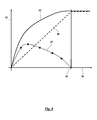
- a level 43 of the cabin is shown as a function of time 44 while driving through a depression.
- the solid line 45 indicates an ideal level change of the level of the car for which the car would not change its absolute height despite entering into the subsidence. It can be seen that the level must rise to compensate for the lowering of the roadway in the area of the depression.
- the dashed line 46 the change in the level of the chassis is shown, which can be brought about with simultaneous ventilation of all bellows 5.
- Throttle effects in solenoid valves and wires is finite rate of change of the level.
- line 46 can not follow line 45 due to these throttling effects.
- the ventilation of the air spring bellows 18 is thereby dimensioned just so that the sum of the level changes according to the lines 46, 47 just corresponds to the total required level change according to line 45. It can be seen in Fig. 4 in that the auxiliary loading of the air spring bellows 18 of the cabin air suspension system 3 is reduced over time, while with increasing pressurization of the cabin air suspension system 3, the level of the chassis corresponding to the line 46 continues to increase. At a point in time 48, the relative level between the cabin and the driver's cab can then again correspond to the initial relative level, since then the level of the chassis according to line 46 corresponds to the required level change 45.
Abstract
Die Erfindung betrifft eine Druckluftanlage (1) für ein Nutzfahrzeug, welche über eine Chassis-Luftfederungsanlage (2) sowie eine Kabinen-Luftfederungsanlage (3) verfügt. Die Steuerung oder Regelung sowohl der Chassis-Luftfederungsanlage (2) als auch der Kabinen-Luftfederungsanlage (3) erfolgt durch ein einziges zentrales Steuergerät (30), wobei die Steuerungen oder Regelungen der Chassis-Luftfederungsanlage (2) und der Kabinen-Luftfederungsanlage (3) miteinander koordiniert und aufeinander abgestimmt sind. Hierdurch kann die Schnelligkeit der Steuerung oder Regelung erhöht werden und eine größere Steuerungs- oder Regelungsgüte erzielt werden.The invention relates to a compressed air system (1) for a commercial vehicle, which has a chassis air suspension system (2) and a cabin air suspension system (3). The control or regulation of both the chassis air suspension system (2) and the cabin air suspension system (3) by a single central control unit (30), wherein the controls or regulations of the chassis air suspension system (2) and the cabin air suspension system (3 ) are coordinated and coordinated with each other. As a result, the speed of the control or regulation can be increased and a greater control or regulation quality can be achieved.
Description
Die Erfindung betrifft ein Steuergerät für eine Druckluftanlage eines Nutzfahrzeugs, eine Druckluftanlage eines Nutzfahrzeugs mit einem derartigen Steuergerät sowie ein Verfahren zum Betrieb einer Druckluftanlage eines Nutzfahrzeugs.The invention relates to a control device for a compressed air system of a commercial vehicle, a compressed air system of a commercial vehicle with such a control device and a method for operating a compressed air system of a commercial vehicle.
Moderne Nutzfahrzeuge verfügen einerseits über eine Chassis-Luftfederungsanlage sowie andererseits über eine Kabinen-Luftfederanlage, welche in einer Druckluftanlage pneumatisch miteinander verbunden oder pneumatisch entkoppelt ausgebildet sein können.Modern commercial vehicles on the one hand have a chassis air suspension system and on the other hand via a cabin air suspension system, which may be pneumatically interconnected or pneumatically decoupled in a compressed air system.
Hierbei dient die Chassis-Luftfederungsanlage der Steuerung oder Regelung eines konstanten oder variierenden Niveaus des Chassis gegenüber der Fahrbahn, was quasistationär, beispielsweise für das Be- und Entladen, und/oder dynamisch während der Fahrt des Nutzfahrzeugs beim Beschleunigen, Bremsen und Kurvenfahrt zwecks Vermeidung unerwünschter Rollbewegungen, Nickbewegungen oder Gierbewegungen des Chassis der Fall sein kann. Die Steuerung oder Regelung der Chassis-Luftfederungsanlage erfolgt über die Veränderung der Beaufschlagung von Luftfederbälgen, welche zwischen eine Achse des Nutzfahrzeugs und/oder Rädern des Nutzfahrzeugs und dem Chassis angeordnet sind, und/oder Verstellung von Dämpfern, welche zwischen Rädern und Chassis oder Achse und Chassis wirken. Des Weiteren ist eine Steuerung oder Regelung einer Chassis-Luftfederungsanlage erforderlich zwecks Anpassung des Niveaus an eine Rampe zum Be- und Entladen, was automatisch oder durch manuelle Steuerung durch den Fahrer erfolgen kann.Here, the chassis air suspension system is used to control or regulate a constant or varying level of the chassis relative to the roadway, which is quasi-stationary, for example for loading and unloading, and / or dynamically while the commercial vehicle is driving when accelerating, braking and cornering to avoid unwanted Rolling, pitching or yawing the chassis may be the case. The control or regulation of the chassis air suspension system via the change in the application of air spring bellows, which are arranged between an axis of the utility vehicle and / or wheels of the utility vehicle and the chassis, and / or adjustment of dampers, which between wheels and chassis or axle and Chassis act. Furthermore, control of a chassis air suspension system is required to adapt the level to a loading and unloading ramp, which may be automatic or by manual control by the driver.
Mittels der Kabinen-Luftfederungsanlage ist die Kabine des Nutzfahrzeugs mit Luftfederbälgen und Dämpfern gegenüber dem Chassis abgestützt. Die Steuerung oder Regelung der Kabinen-Luftfederungsanlage erfolgt bspw. mit dem Ziel, die Kabine zum Ein- und Aussteigen abzusenken, das Niveau der Kabine von der Beladung und dem Gewicht der in der Kabine angeordneten Personen unabhängig zu gestalten und dynamische Bewegungen der Kabine, insbesondere eine Nickbewegung, eine Rollbewegung und eine Gierbewegung der Kabine, zumindest zu reduzieren.By means of the cabin air suspension system, the cabin of the commercial vehicle is supported with air bellows and dampers against the chassis. The control or regulation of the cabin air suspension system takes place, for example, with the aim of lowering the car for getting in and out, to make the level of the car independent of the loading and the weight of the people arranged in the cabin and dynamic movements of the cabin, in particular a pitching motion, a rolling motion and a yawing motion of the car, at least to reduce.
Gemäß
Die Druckschrift
Aus
Aus
Der vorliegenden Erfindung liegt die Aufgabe zugrunde, ein Steuergerät für eine Druckluftanlage eines Nutzfahrzeugs, eine Druckluftanlage und ein Verfahren zum Betrieb einer Druckluftanlage vorzuschlagen, welches oder welche über erweiterte Eingriffsmöglichkeiten für die Steuerung oder Regelung des statischen und/oder dynamischen Niveaus des Chassis und/oder der Kabine des Nutzfahrzeugs verfügt.The present invention has for its object to propose a control unit for a compressed air system of a commercial vehicle, a compressed air system and a method for operating a compressed air system, which or which more advanced intervention options for the control or regulation of the static and / or dynamic level of the chassis and / or the cabin of the commercial vehicle has.
Die Aufgabe der Erfindung wird erfindungsgemäß mit den Merkmalen der unabhängigen Patentansprüche gelöst. Weitere bevorzugte erfindungsgemäße Ausgestaltungen sind den abhängigen Patentansprüchen zu entnehmen.The object of the invention is achieved with the features of the independent claims. Further preferred embodiments according to the invention can be found in the dependent claims.
Die vorliegende Erfindung beruht auf der Erkenntnis, dass es vorteilhaft ist, wenn ein einziges Steuergerät sowohl für die Steuerung oder Regelung einer Chassis-Luftfederungsanlage als auch für die Steuerung oder Regelung eines Kabinen-Luftfederungsanlage zuständig ist:
- Gegenüber der Verwendung von zwei Steuergeräten führt die Verwendung eines einzigen multifunktionalen Steuergerätes zu einer Reduzierung der Zahl der Bauelemente, des Bauvolumens, des Montageaufwandes und/oder der Kosten.
- Ohne dass hierdurch die Erfindung beschränkt werden soll, kann zum Zwecke der Vereinfachung das Nutzfahrzeug stark vereinfacht als Feder-Masse-Dämpfer-System mit einem vertikalen Freiheitsgrad betrachtet werden, bei welchem die Masse von der Masse des Fahrzeugaufbaus (ggf. einschließlich einer Beladung) gebildet ist und die Federsteifigkeit und Dämpfung von der Chassis-Luftfederungsanlage bereitgestellt ist. Mit diesem Feder-Masse-Dämpfer-System ist ein weiteres vertikales Feder-Masse-Dämpfer-System gekoppelt, welches ebenfalls einen vertikalen Freiheitsgrad besitzt, die Abstützung der Kabine an dem Chassis abbildet und bei welchem die Masse mit der Masse der Kabine (ggf. einschließlich einer Beladung mit dem Fahrergewicht) und die Feder von den Luftfederbälgen der Kabinen-Luftfederungsanlage gebildet ist und der Dämpfer eine Dämpfungswirkung der Kabinen-Luftfederungsanlage beschreibt. Das derart gebildete System bildet somit insgesamt ein Schwingungssystem mit zwei Massen und zwei Freiheitsgraden, welches sich aus einem Chassis-Teilschwingungssystem und einem Kabinen-Teilschwingungssystem zusammensetzt. Erfolgt durch zwei Steuergeräte die separate Steuerung oder Regelung für die beiden genannten Teilschwingungssysteme, ergibt sich zumindest in einigen Teilbetriebsbereichen eine suboptimale Steuerung oder Regelung. Dieses soll anhand eines Beispiels erläutert werden, ohne dass dieses Beispiel die Erfindung einschränken soll:
- Überfährt das Nutzfahrzeug mit den Rädern eine Fahrbahnunebenheit, welche idealisiert und ebenfalls vereinfacht als Stufe angesehen werden kann, führt dies zu einer transienten Schwingung des Chassis-Teilschwingungssystems, deren Ausmaß durch die Steuerung oder Regelung der Chassis-Luftfederungsanlage allenfalls reduziert wird. Ursache hierfür ist beispielsweise, dass bei dem Überfahren der Fahrbahnunebenheit die Chassis-Luftfederungsanlage nicht so schnell be- und entlüftet werden kann, dass trotz der Fahrbahnunebenheit die Niveauhöhe unverändert bleibt. Hierfür verantwortlich ist einerseits die begrenzte Schnelligkeit der Steuerung oder Regelung einer Steuereinheit und andererseits eine Begrenzung der Be- und Entlüftungsquerschnitte. Verbleibende Schwingungen des Chassis-Teilschwingungssystems pflanzen sich dann aber fort zu dem Kabinen-Teilschwingungssystem, welches somit ebenfalls Schwingungen ausgesetzt ist. Wünschenswert wäre, dass eine derartige Anregung von Schwingungen des Kabinen-Teilschwingungssystems gänzlich vermieden werden. Erschwerend kann hinzukommen, dass je nach Auslegung der unterschiedlichen Steuerungen oder Regelungen einerseits der Chassis-Luftfederungsanlage und andererseits der Kabinen-Luftfederungsanlage die Aktionen der beiden Steuerungen oder Regelungen schlimmstenfalls zu einer Instabilität führen können. Schließlich kann es infolge der Schwingungen des Kabinen-Teilschwingungssystems zur Ausübung von Kräften durch das Kabinen-Teilschwingungssystem auf das Chassis-Teilschwingungssystem kommen, welche die Steuerung oder Regelung der Chassis-Luftfederungsanlage beeinträchtigen oder von dieser berücksichtigt werden müssen.
- Selbst wenn ein Steuergerät zur Steuerung oder Regelung einer Chassis-Luftfederungsanlage und ein Steuergerät zur Steuerung oder Regelung einer Kabinen-Luftfederungsanlage über ein Bussystem miteinander kommunizieren, führt die Kommunikation der Steuergeräte und die Verarbeitung der zwischen den Steuergeräten ausgetauschten Signale zu einer Zeitverzögerung, welche (selbst wenn diese nur im Bereich von Millisekunden liegt) nachteilig für die Steuerungs- oder Regelungsgüte ist.
- Compared with the use of two control units, the use of a single multifunctional control unit leads to a reduction in the number of components, the volume of construction, the assembly costs and / or the costs.
- Without thereby limiting the invention, for the sake of simplicity, the commercial vehicle can be considered greatly simplified as a spring-mass-damper system with a vertical degree of freedom, in which the mass of the mass of the vehicle body (possibly including a load) formed is and the spring stiffness and damping provided by the chassis air suspension system. With this spring-mass-damper system is coupled another vertical spring-mass-damper system, which also has a vertical degree of freedom, the support of the cabin maps to the chassis and in which the mass with the mass of the cabin (possibly. including a load of the driver's weight) and the spring is formed by the air spring bellows of the cabin air suspension system and the damper describes a damping effect of the cabin air suspension system. The system thus formed thus forms a total of a two-mass, two-degree-of-freedom vibration system composed of a chassis sub-system and a cabin sub-system. If, by means of two control units, the separate control or regulation for the two mentioned partial vibration systems results, at least in some partial operating ranges, a suboptimal control or regulation results. This will be explained by way of example, without this example being intended to limit the invention:
- If the commercial vehicle with the wheels overtakes a road surface unevenness which can be regarded as idealized and also simplified, this leads to a transient vibration of the chassis partial vibration system, the extent of which is at best reduced by the control or regulation of the chassis air suspension system. The reason for this is, for example, that when driving over the bumpy road surface, the chassis air suspension system can not be aerated and vented so quickly that the level height remains unchanged despite the road surface unevenness. Responsible for this is on the one hand the limited speed of the control or regulation of a control unit and on the other hand, a limitation of the ventilation cross sections. Remaining vibrations of the chassis partial vibration system but then propagate to the cabin partial vibration system, which thus also vibrations is exposed. It would be desirable that such excitation of vibrations of the cabin partial vibration system are completely avoided. To make matters worse, depending on the design of the different controls or regulations on the one hand, the chassis air suspension system and on the other hand, the cabin air suspension system, the actions of the two controls or regulations in the worst case can lead to instability. Finally, as a result of the vibrations of the cabin partial vibration system for exerting forces through the cabin partial vibration system, the chassis partial vibration system may interfere with or be taken into account by the control or regulation of the chassis air suspension system.
- Even if a controller for controlling a chassis air suspension system and a controller for controlling a cabin air suspension system communicate with each other via a bus system, the communication of the controllers and the processing of the signals exchanged between the controllers results in a time delay which (self if this is only in the range of milliseconds) is disadvantageous for the control or regulation quality.
Vor diesem Hintergrund schlägt die Erfindung ein Steuergerät vor, welches sowohl mit Steuerlogik zur Steuerung oder Regelung einer Chassis-Luftfederungsanlage für eine Abstützung eines Chassis des Nutzfahrzeugs als auch mit Steuerlogik zur Steuerung oder Regelung einer Kabinen-Luftfederungsanlage für eine Abstützung einer Fahrerkabine des Nutzfahrzeugs ausgestattet ist. Hierbei können die genannten Steuerlogiken Bestandteil einer einzigen Software sein. Möglich ist auch, dass die genannten Steuerlogiken auf dem Steuergerät parallelisiert sind oder auf Teilprozessoren des Steuergeräts ausgeführt werden. Möglich ist, dass durch die Verwendung des einen multifunktionalen Steuergeräts Komponenten wie eine Spannungsversorgung, Kommunikationstreiber, Sensorauswerteschaltungen u. ä. sowohl für die Steuerung oder Regelung der Chassis-Luftfederungsanlage als auch die Steuerung oder Regelung der Kabinen-Luftfederungsanlage genutzt werden. Möglich ist auch, dass trotz der Zusammenfassung der beiden Steuerlogiken in einem Steuergerät die Steuerlogiken derart voneinander entkoppelt sind, dass die beiden Steuerlogiken für sich geändert werden können, was vorteilhaft ist für einen etwaigen Softwareupdate. Im Extremfall können die beiden Steuerlogiken softwareseitig weitgehend autark ausgebildet sein.Against this background, the invention proposes a control unit which is equipped both with control logic for controlling or regulating a chassis air suspension system for supporting a chassis of the commercial vehicle and with control logic for controlling or regulating a cabin air suspension system for supporting a driver's cab of the utility vehicle , In this case, the said control logics can be part of a single software. It is also possible that the said control logics are parallelized on the control unit or executed on sub-processors of the control unit. It is possible that through the use of a multifunctional controller components such as a power supply, communication driver, Sensorauswerteschaltungen u. Ä. Used both for the control or regulation of the chassis air suspension system as well as the control or regulation of the cabin air suspension system. It is also possible that despite the combination of the two control logics in a control unit, the control logics are decoupled from each other so that the two control logics can be changed for themselves, which is advantageous for any software update. In extreme cases, the two control logics can be made largely self-sufficient by software.
Erfindungsgemäß sind die Steuerungen oder Regelungen der Chassis-Luftfederungsanlage und der Kabinen-Luftfederungsanlage derart miteinander koordiniert, dass die Steuerungs- oder Regelungsmaßnahmen der Chassis-Luftfederungsanlage einerseits und der Kabinen-Luftfederungsanlage andererseits nicht unabhängig voneinander bestimmt werden, sondern diese vielmehr gegenseitig voneinander abhängig sind oder sich gegenseitig beeinflussen. Möglich ist, dass durch die beiden Steuerlogiken in dem Steuergerät das Chassis-Teilschwingungssystem und das Kabinen-Teilschwingungssystem gemeinsam als ein Gesamt-Schwingungssystem betrachtet werden mit den beiden Eingriffsmöglichkeiten durch die Steuerlogiken an der Chassis-Luftfederungsanlage und der Kabinen-Luftfederungsanlage, wobei dann in dem Gesamt-Schwingungssystem auch die zuvor erläuterten Wechselwirkungen zwischen den Teilschwingungssystemen berücksichtigt werden können. Dies soll anhand des folgenden, stark vereinfachenden und die Erfindung nicht beschränkenden Beispiels erläutert werden:
- Wird eine Fahrbahnunebenheit überfahren mit einer Änderung der Fahrbahnhöhe von 5 cm/sec und führt die Steuerung oder Regelung der Chassis-Luftfederungsanlage lediglich zu einer maximalen Änderungsgeschwindigkeit
von 3 cm/sec, kann es vorteilhaft sein, zusätzlich zur Steuerung oder Regelung der Chassis-Luftfederungsanlage auch die Kabinen-Luftfederungsanlage derart anzusteuern oder zu regeln, dass sich eine Änderung des Niveaus der Kabine über dem Chassis ergibt mit einerÄnderungsgeschwindigkeit von 2 cm/sec. Auch wenn somit das Chassis mit dem Überfahren der Fahrbahnunebenheit seine Höhe mit einerÄnderungsgeschwindigkeit von 2 cm/sec verändert, kann diese unzureichende Steuerung oder Regelung der Chassis-Luftfederungsanlage von der Kabine ferngehalten werden durch die koordinierte Steuerung oder Regelung der Kabinen-Luftfederungsanlage, womit dann trotz der nicht vollständigen Ausreglung der Niveauänderung des Chassis die Kabine die erforderliche Niveauänderung erfährt, womit die unvermeidbaren Schwankungen des Chassis von der Kabine und damit dem Fahrer ferngehalten werden. (Dem Fachmann wird ersichtlich sein, dass die zuvor genannte Erläuterung stark vereinfachend ist und auf einer an sich unzutreffenden statischen Betrachtung basiert, während u. U. eine tatsächliche Koordinierung der Steuerungen oder Regelungen eine dynamische Betrachtung erfordert, welche u. U. auch eine komplexe Abbildung der Vorgänge mit Ersatzmodellen oder Übertragungsverhalten erfordert.) Somit kann erfindungsgemäß durch die Koordinierung der Steuerungen oder Regelungen der Chassis-Luftfederungsanlage und der Kabinen-Luftfederungsanlage eine Verbesserung der Steuerungs- oder Regelungsgüte herbeigeführt werden.
- If an uneven road surface is run over with a change of the roadway height of 5 cm / sec and the control or regulation of the chassis air suspension system leads only to a maximum rate of change of 3 cm / sec, it may be advantageous, in addition to the control or regulation of the chassis air suspension system as well to control or regulate the cabin air suspension system such that there is a change in the level of the cabin above the chassis at a rate of change of 2 cm / sec. Thus, even if the chassis changes its height at a rate of change of 2 cm / sec as it passes over the road surface, this inadequate control of the chassis air suspension system can be kept away from the cab by the coordinated control of the cabin air suspension system despite the incomplete control of the level change of the chassis, the cab experiences the required level change, thus keeping the unavoidable chassis fluctuations away from the cab and thus the driver. (It will be apparent to those skilled in the art that the above explanation is highly simplistic and based on inherently incorrect static consideration, while in some circumstances actual coordination of the controls may require dynamic consideration, which may also be complex Illustration of the processes with replacement models or transmission behavior requires.) Thus, according to the invention can be brought about by the coordination of the controls or regulations of the chassis air suspension system and the cabin air suspension system an improvement of the control or regulation quality.
Grundsätzlich möglich ist, dass im Rahmen der Erfindung die Steuerungen oder Regelungen ausschließlich die Be- und Entlüftung der beteiligten Luftfederbälge der Chassis-Luftfederungsanlage und der Kabinen-Luftfederungsanlage steuern oder regeln. In Weiterbildung der Erfindung ist das Steuergerät zusätzlich mit Steuerlogik ausgestattet, über welche mindestens ein Dämpfer des Chassis (oder der Kabine) gesteuert oder geregelt wird. Hierbei ist die Steuerung oder Regelung des mindestens einen Dämpfers des Chassis (und/oder der Kabine) mit den Steuerungen oder Regelungen der Chassis-Luftfederungsanlage und der Kabinen-Luftfederungsanlage koordiniert. Um lediglich ein (die Erfindung nicht beschränkendes) Beispiel zu nennen, kann für den Fall, dass die Steuerung oder Regelung der Chassis-Luftfederungsanlage und/oder der Kabinen-Luftfederungsanlage eine große Änderungsgeschwindigkeit eines Niveaus erfordert, gleichzeitig eine Dämpfung eines parallel zu dem jeweiligen Luftfederbalg wirkenden Dämpfers verringert werden, so dass die Be- oder Entlüftung des Luftfederbalges nicht gegen die Kraft eines Dämpfers erfolgen muss, womit die Schnelligkeit der Steuerung oder Regelung reduziert werden würde.In principle, it is possible that in the context of the invention, the controls or regulations exclusively control or regulate the ventilation of the involved air suspension bellows of the chassis air suspension system and the cabin air suspension system. In a further development of the invention, the control unit is additionally equipped with control logic via which at least one damper of the chassis (or the cab) is controlled or regulated. Here, the control or regulation of the at least one damper of the chassis (and / or the cabin) is coordinated with the controls or regulations of the chassis air suspension system and the cabin air suspension system. In order to give only an example (not limiting the invention), in the event that the control or regulation of the chassis air suspension system and / or the cabin air suspension system requires a large rate of change of a level, at the same time a damping of a parallel to the respective air spring bellows acting damper can be reduced, so that the ventilation of the air spring bellows must not take place against the force of a damper, whereby the speed of the control or regulation would be reduced.
Möglich ist auch, dass das Steuergerät mit Steuerlogik ausgestattet ist, über welche eine Steuerung oder Regelung einer Abstützung eines in der Kabine angeordneten Sitzes erfolgt. Hierbei kann die Steuerung oder Regelung einer Feder, insbesondere eines Luftfederbalges, und/oder eines Dämpfers, mit welchem der Sitz gegenüber der Kabine abgestützt ist, hinsichtlich der Höhe des Sitzes, der Federsteifigkeit und/oder der Dämpfung erfolgen. In diesem Fall ist die Steuerung der Abstützung des Sitzes mit den Steuerungen oder Regelungen der Chassis-Luftfederungsanlage und der Kabinen-Luftfederungsanlage koordiniert. Auf diese Weise kann u. U. eine trotz der Steuerung oder Regelung der Chassis-Luftfederungsanlage und der Kabinen-Luftfederungsanlage verbleibende Schwingung der Kabine zumindest teilweise von dem Fahrer ferngehalten werden.It is also possible that the control unit is equipped with control logic, via which a control or regulation of a support arranged in the cabin seat takes place. In this case, the control or regulation of a spring, in particular an air spring bellows, and / or a damper, with which the seat is supported relative to the cabin, with respect to the height of the seat, the spring stiffness and / or the damping take place. In this case, the control of the seat support is coordinated with the controls or controls of the chassis air suspension system and the cabin air suspension system. In this way u. U. despite the control or regulation of the chassis air suspension system and the cabin air suspension system remaining vibration of the cabin are at least partially kept away from the driver.
Die Steuerung oder Regelung der Chassis-Luftfederungsanlage und/oder Kabinen-Luftfederungsanlage erfolgt unter direkter Steuerung oder Regelung der Be- und Entlüftung oder unter Vorsteuerung von be- und entlüftenden Ventilen mittels von dem Steuergerät über elektrische Steuersignale angesteuerten Magnetventilen, welche an beliebiger Stelle in dem Nutzfahrzeug angeordnet sein können. Möglich ist, dass derartige Magnetventile in einer elektropneumatischen Kabinen-Steuereinheit oder einer elektropneumatischen Chassis-Steuereinheit zusammengefasst sein können. Hierbei können die genannten Steuereinheiten auch Module bilden, welche auch mit anderen Steuereinheiten zu einer Gesamteinheit zusammengefasst sein können. Für einen besonderen Vorschlag der Erfindung bildet das Steuergerät gemeinsam mit einer elektropneumatischen Kabinen-Steuereinheit und/oder einer elektropneumatischen Chassis-Steuereinheit eine Baueinheit, wobei auch möglich ist, dass in diese Baueinheit für die Steuerung oder Regelung verwendete Sensoren integriert sind, über welche beispielsweise ein gesteuerter oder geregelter Druck überwacht wird.The control or regulation of the chassis air suspension system and / or cabin air suspension system takes place under direct control or regulation of ventilation and under pilot control of ventilation and exhaust valves by means of the control unit via electrical control signals controlled solenoid valves, which at any point in the Can be arranged commercial vehicle. It is possible that such solenoid valves may be combined in an electropneumatic cab control unit or an electropneumatic chassis control unit. In this case, the said control units can also form modules, which are also combined with other control units to form a complete unit could be. For a particular proposal of the invention, the control unit together with an electropneumatic cabin control unit and / or an electropneumatic chassis control unit, a structural unit, wherein it is also possible that sensors used in this unit for the control or regulation are integrated, via which for example a controlled or regulated pressure is monitored.
In weiterer Ausgestaltung der Erfindung besitzt das Steuergerät mindestens einen steuernden oder regelnden Ausgang für eine Kabinen-Luftfederungsanlage und/oder eine Chassis-Luftfederungsanlage.In a further embodiment of the invention, the control unit has at least one controlling or regulating output for a cabin air suspension system and / or a chassis air suspension system.
Für eine Ausgestaltung des erfindungsgemäßen Steuergerätes besitzt dieses Steuerlogik zur Verarbeitung mindestens eines Eingangssignals.
- Das Eingangssignal kann ein Niveau des Chassis sein, beispielsweise das Niveau eines Luftfederbalges, einer Achse oder eines beliebigen Ortes des Nutzfahrzeuges. Auf Grundlage einer mittels der Steuerlogik erkannten Änderung des Niveaus kann dann eine Steuerung oder Regelung erfolgen. Das Entsprechende gilt für die Ausbildung des Eingangssignals als Niveauänderungsgeschwindigkeit.
- Möglich ist, dass die Steuerlogik ein Eingangssignal in Form eines Druckes oder eine Druckänderungsgeschwindigkeit eines Luftfederbalges der Chassis-Luftfederungsanlage verarbeitet. Beispielsweise kann eine Druckänderung auf eine veränderte Beladung und/oder eine dynamische Beanspruchung des Luftfederbalges hindeuten.
- Ebenfalls möglich ist, dass als Eingangssignal ein Betriebsparameter eines Dämpfers des Chassis, insbesondere ein Drosselquerschnitt, eine Ventilstellung des Dämpfers, eine Relativgeschwindigkeit des Dämpfers o. ä. verarbeitet wird.
- Entsprechend kann als Eingangssignal ein Niveau, eine Niveauänderungsgeschwindigkeit der Kabine, ein Druck, eine Druckänderungsgeschwindigkeit eines Luftfederbalges der Kabinen-Luftfederungsanlage und/oder ein Betriebsparameter eines Dämpfers der Kabine verwendet werden, welches dann durch die Steuerlogik des Steuergeräts ausgewertet wird.
- Durchaus möglich ist, dass zusätzlich die Auswertung eines Eingangssignals erfolgt, bei welchem es sich um das Signal eines anderen Steuergeräts handelt. Um lediglich ein Beispiel zu nennen, kann eine Verarbeitung eines Signals eines ABS- oder EBS-Steuergeräts erfolgen, so dass bereits vor oder mit Einleitung einer Bremsaktion geeignete Gegenmaßnahmen durch das Steuergerät für die Steuerung oder Regelung der Kabinen-Luftfederungsanlage und/oder der Chassis-Luftfederungsanlage getroffen werden können. Beispielsweise kann bei einer bevorstehenden Bremsbetätigung eine Erhöhung einer Dämpfung ausgesteuert werden und/oder einer durch die Bremsbetätigung vorhergesehenen Nickbewegung des Fahrzeugs wird vorgebeugt durch Belüftung von einer Vorderachse zugeordneten Luftfederbälgen.
- Möglich ist auch, dass dem Steuergerät ein Signal über ein Bussystem zugeführt wird.
- Des Weiteren kann dem Steuergerät als Eingangssignal ein Reifendruck zugeführt werden. Dieser Ausgestaltung liegt die Erkenntnis zugrunde, dass sich das dynamische Verhalten des Schwingungssystems je nach Reifendruck, also elastischer Abstützung des Rades auf der Fahrbahn, verändert. Durch Verarbeitung des Reifendruckes kann somit letztendlich die Steuerungs- oder Regelungsgüte erhöht werden.
- Ebenfalls möglich ist, dass als Eingangssignal von dem Steuergerät eine Bremskraft oder ein Bremssignal verarbeitet wird, um bereits rechtzeitig Kenntnisse über die Gefahr der Entstehung einer Nickbewegung mit der Bremsbetätigung informiert zu werden und rechtzeitig geeignete Gegenmaßnahmen aussteuern oder ausregeln zu können.
- Ebenfalls möglich ist, dass als Eingangssignal ein Signal eines Navigationssystems oder eines Ortserkennungssystems (GPS) verwendet wird. Beispielsweise kann mit dem Erkennen durch das Navigationssystem, dass eine Annäherung an das Ziel erfolgt, ein Veränderung eines Niveau des Chassis, der Kabine und/oder des Fahrersitzes herbeigeführt werden, welche ein Aussteigen des Fahrers aus der Kabine vereinfacht. Ebenfalls möglich ist, dass für den Fall, dass mittels des Ortserkennungssystems oder Navigationssystems erkannt wird, dass eine Annäherung an eine Rampe erfolgt, wo aller Voraussicht nach ein Be- oder Entladen des Nutzfahrzeugs erfolgt, eine automatische Niveauänderung herbeigeführt wird zwecks Anpassung an die Rampenhöhe. Hinsichtlich weiterer Details zu dieser Ausgestaltung wird auf die
Druckschrift DE 10 2011 000 668 B4 - Ebenfalls möglich ist, dass als Eingangssignal von der Steuerlogik des Steuergeräts eine Geschwindigkeit des Nutzfahrzeugs verarbeitet wird.
- Wird als Eingangssignal ein Lenkwinkel des Nutzfahrzeugs berücksichtigt, kann eine geeignete Maßnahme ergriffen werden, um rechtzeitig einer Rollbewegung des Nutzfahrzeugs infolge einer Kurvenfahrt entgegenzuwirken.
- Ebenfalls möglich ist, dass als Eingangssignal von der Steuerlogik des Steuergeräts eine aktuelle oder zukünftige Fahrbahnneigung berücksichtigt wird, so dass rechtzeitig geeignete Gegenmaßnahmen ergriffen werden können, um einer Roll- oder Nickbewegung des Fahrzeugs infolge der aktuellen oder zukünftigen Fahrbahnneigung rechtzeitig entgegenwirken zu können.
- Eine weitere mögliche Eingangsgröße stellt die Beladung des Nutzfahrzeugs dar, welche signifikant die Systemgrößen des Schwingungssystems, nämlich die Masse, verändern kann, womit auch eine veränderte Steuerung oder Regelung durch das Steuergerät erfolgen muss.
- Ebenfalls möglich ist, dass als Eingangssignal von dem Steuergerät ein Betriebssignal eines Anhängers oder Aufliegers verarbeitet wird. Im einfachsten Fall handelt es sich bei dem Betriebssignal um ein Signal dahingehend, ob überhaupt ein Anhänger oder Auflieger mit einem Zugfahrzeug gekoppelt ist. Somit kann durch die Steuerung oder Regelung berücksichtigt werden, ob die Dynamik des Schwingungssystems von dem Anhänger oder Auflieger beeinflusst wird oder nicht. Des Weiteren kann das Betriebssignal des Anhängers oder Aufliegers bspw. in einer Kopplungskraft, einer ermittelten Masse des Anhängers oder Aufliegers, einem Beladungszustand des Anhängers oder Aufliegers, einer Kenngröße für die Fahrstabilität des Anhängers oder Aufliegers, ein Winkel zwischen den Längsachse des Anhängers und des Aufliegers u. ä. bestehen.
- Möglich ist auch, dass als Eingangssignal von dem Steuergerät ein Signal eines Beschleunigungssensors, eines Gierratensensors, eines Rollsensors und/oder eines Nicksensors verwendet wird.
- Insbesondere für den Fall, dass über das Steuergerät auch eine Steuerung oder Regelung der Abstützung eines in der Kabine angeordneten Sitzes erfolgt, kann es von Vorteil sein, wenn als Eingangsgröße von dem Steuergerät ein automatisch ermitteltes Gewicht des Fahrers auf dem Sitz oder ein manuell vorgegebenes Gewicht berücksichtigt wird.
- Möglich ist, dass Auswirkungen eines Schaltvorgangs auf die Chassis-Luftfederungsanlage und/oder die Kabinen-Luftfederungsanlage und ggf. eine Abstützung eines in der Kabine angeordneten Sitzes vermieden werden sollen, insbesondere ein Nicken infolge einer Längsverzögerung während des Schaltvorgangs. Hierzu kann es vorteilhaft sein, wenn als Eingangsgröße von dem Steuergerät ein Signal hinsichtlich eines Schaltvorgangs verarbeitet wird.
- Möglich ist auch, dass als Eingangsgröße eine Bremspedalstellung, eine Gaspedalstellung und/oder eine Bremspedalstellungsänderungsgeschwindigkeit oder eine Gaspedalstellungsänderungsgeschwindigkeit verarbeitet wird.
- Gemäß einem weiteren Vorschlag kann das Signal eines Retarders verarbeitet werden.
- The input signal may be a level of the chassis, such as the level of an air spring bellows, an axle or any location of the utility vehicle. On the basis of a detected by the control logic change in the level can then be controlled or regulated. The same applies to the formation of the input signal as a level change rate.
- It is possible that the control logic processes an input signal in the form of a pressure or a rate of pressure change of an air spring bellows of the chassis air suspension system. For example, a change in pressure may indicate a change in load and / or dynamic loading of the air spring bellows.
- It is also possible that an operating parameter of a damper of the chassis, in particular a throttle cross section, a valve position of the damper, a relative speed of the damper o. Ä. Is processed as an input signal.
- Accordingly, a level, a level change rate of the car, a pressure, a pressure change speed of a bellows of the cabin air suspension system and / or an operating parameter of a damper of the cabin can be used as an input signal, which is then evaluated by the control logic of the controller.
- It is quite possible that additionally takes place the evaluation of an input signal, which is the signal of another controller. To name just one example, processing of a signal of an ABS or EBS control unit can take place so that suitable countermeasures are taken by the control unit for controlling or regulating the cabin air suspension system and / or the chassis control unit before or with the initiation of a braking action. Air suspension system can be taken. For example, in the case of an imminent brake actuation, an increase in damping can be controlled and / or a pitching motion of the vehicle anticipated by the brake operation is prevented by ventilation of air suspension bellows associated with a front axle.
- It is also possible that the control unit, a signal is supplied via a bus system.
- Furthermore, a tire pressure can be supplied to the control unit as an input signal. This refinement is based on the knowledge that the dynamic behavior of the vibration system changes depending on tire pressure, ie elastic support of the wheel on the roadway. By processing the tire pressure, the control or regulation quality can thus ultimately be increased.
- It is also possible that as input signal from the controller, a braking force or a brake signal is processed to be informed in good time about the risk of the emergence of a pitching motion with the brake and timely appropriate countermeasures aussteuern or to be able to.
- It is also possible that a signal of a navigation system or a location recognition system (GPS) is used as the input signal. For example, with the recognition by the navigation system of approaching the target, a change in a level of the chassis, the cab, and / or the driver's seat can be brought about, which facilitates the driver getting out of the cab. It is also possible that in the event that it is detected by means of the location recognition system or navigation system, that an approach to a ramp takes place, where in all probability a loading or unloading of the commercial vehicle, an automatic level change is brought about for the purpose of adaptation to the ramp height. For further details of this embodiment is on the
document DE 10 2011 000 668 B4 - It is also possible that as input signal from the control logic of the controller, a speed of the commercial vehicle is processed.
- If a steering angle of the commercial vehicle is taken into account as the input signal, a suitable measure can be taken to counteract in good time a rolling movement of the commercial vehicle as a result of cornering.
- It is also possible that as input signal from the control logic of the controller, a current or future roadway inclination is taken into account, so that timely appropriate countermeasures can be taken to counteract a rolling or pitching motion of the vehicle due to the current or future roadway tendency in a timely manner.
- Another possible input variable is the load of the commercial vehicle, which can significantly change the system variables of the vibration system, namely the mass, which also requires a change in control or regulation by the control unit.
- It is also possible that an operating signal of a trailer or semitrailer is processed as an input signal from the control unit. In the simplest case, the operating signal is a signal as to whether a trailer or semitrailer is ever coupled to a towing vehicle. Thus, by the control or regulation can be considered whether the dynamics of the vibration system is influenced by the trailer or semi-trailer or not. Furthermore, the operating signal of the trailer or semitrailer, for example, in a coupling force, a determined mass of the trailer or semitrailer, a load condition of the trailer or semitrailer, a parameter for the driving stability of the trailer or trailer, an angle between the longitudinal axis of the trailer and the trailer u. Ä. exist.
- It is also possible that a signal of an acceleration sensor, a yaw rate sensor, a roll sensor and / or a pitch sensor is used as the input signal from the control unit.
- In particular, in the event that via the control unit and a control or regulation of the support of a arranged in the cabin seat, it may be advantageous if the input of the control unit automatically determined weight of the driver on the seat or a manually predetermined weight is taken into account.
- It is possible that effects of a switching operation on the chassis air suspension system and / or the cabin air suspension system and possibly a support of a seat arranged in the cabin should be avoided, in particular a pitch due to a longitudinal deceleration during the switching operation. For this purpose, it may be advantageous if a signal relating to a switching operation is processed by the control unit as input variable.
- It is also possible that a brake pedal position, an accelerator pedal position and / or a brake pedal position change speed or an accelerator pedal position change speed is processed as an input variable.
- According to another proposal, the signal of a retarder can be processed.
Mit der Steuerlogik des Steuergeräts kann dann durch die Verarbeitung zumindest eines dieser Eingangssignale die Steuerung oder Regelung oder Chassis-Luftfederungsanlage, der Kabinen-Luftfederungsanlage, eines Luftfederbalges für den Sitz und/oder eines Dämpfers des Chassis, der Kabine und/oder des Sitzes erfolgen.With the control logic of the controller can then be carried out by the processing of at least one of these input signals, the control or chassis Luftfederungsanlage, the cabin Luftfederungsanlage, a Luftfederbalges for the seat and / or a damper of the chassis, the cabin and / or the seat.
In weiterer Ausgestaltung der Erfindung ist das Steuergerät mit Steuerlogik ausgestattet, mittels welcher eine automatische Veränderung einer statischen oder mittleren Niveauhöhe des Chassis erfolgt. Beispielsweise kann über das Steuergerät je nach Geschwindigkeit die (mittlere) Niveauhöhe des Chassis angepasst werden. Auch möglich ist, dass die automatische Veränderung in einer Veränderung der Niveauhöhe im Bereich einer Rampe besteht. Um lediglich ein weiteres (nicht beschränkendes) Beispiel zu nennen, kann die automatische Veränderung der Niveauhöhe des Chassis auch erfolgen zwecks Vorbereitung der Kupplung mit einem Anhänger über eine Sattelkupplung oder zwecks Vorbereitung der Aufnahme eines Containers.In a further embodiment of the invention, the control device is equipped with control logic, by means of which an automatic change of a static or average level height of the chassis takes place. For example, depending on the speed, the (average) level height of the chassis can be adjusted via the control unit. It is also possible that the automatic change consists of a change in the level height in the region of a ramp. To mention just another (non-limiting) example, the automatic change The level height of the chassis is also made to prepare the coupling with a trailer via a fifth wheel or in preparation for receiving a container.
Ein weiterer Aspekt der Erfindung widmet sich einer Parksituation. Diese kann beispielsweise automatisch erkannt werden mit dem Erreichen eines vorbestimmten Ortes, welcher beispielsweise in einem Navigationssystem abgelegt ist, insbesondere ein Rast- und Parkplatz oder ein Betriebshof. Ebenfalls möglich ist, dass eine Parksituation erkannt wird mit dauerhafter Geschwindigkeit von Null, Betätigung der Feststellbremse, Deaktivierung der Brennkraftmaschine o. ä. Alternativ oder kumulativ möglich ist, dass der Fahrer über einen Schalter dem Steuergerät mitteilt, dass eine Parksituation vorliegt. In einer derartigen Parksituation ist eine horizontale Ausrichtung der Kabine wünschenswert. Dies erfolgt erfindungsgemäß durch koordinierten Betrieb der Steuerungen oder Regelungen der Chassis-Luftfederungsanlage einerseits und der Kabinen-Luftfederungsanlage andererseits. Möglich ist durchaus, dass hier beispielsweise die Steuerung oder Regelung für eine Raumrichtung durch die Chassis-Luftfederungsanlage und für eine andere Raumrichtung durch die Kabinen-Luftfederungsanlage erfolgt. Vorzugsweise erfolgt aber sogar für eine Raumrichtung die Herbeiführung der horizontalen Ausrichtung der Kabine durch die koordinierte Steuerung oder Regelung sowohl der Chassis-Luftfederungsanlage als auch der Kabinen-Luftfederungsanlage, so dass sich eine gewünschte Anhebung oder Absenkung der Kabine aus der Summe der Anhebung oder Absenkung des Chassis und der Anhebung oder Absenkung der Kabine relativ zu dem Chassis ergibt, wodurch u. U. auch der Ausgleich größerer Neigungswinkel der Fahrbahn, auf welcher das Fahrzeug geparkt wird, möglich ist.Another aspect of the invention is dedicated to a parking situation. This can for example be automatically detected by reaching a predetermined location, which is stored for example in a navigation system, in particular a rest and parking or a depot. It is also possible that a parking situation is detected with permanent speed of zero, actuation of the parking brake, deactivation of the internal combustion engine o. Ä. Alternatively or cumulatively, it is possible that the driver informs the controller via a switch that a parking situation exists. In such a parking situation, a horizontal orientation of the car is desirable. This is done according to the invention by coordinated operation of the controls or regulations of the chassis air suspension system on the one hand and the cabin air suspension system on the other. It is quite possible that here, for example, the control or regulation for a direction in space by the chassis air suspension system and for another spatial direction by the cabin air suspension system takes place. Preferably, however, even for one spatial direction, the horizontal orientation of the car is brought about by the coordinated control or regulation of both the chassis air suspension system and the cabin air suspension system, so that a desired increase or decrease of the car from the sum of the increase or decrease of the Chassis and the raising or lowering of the car relative to the chassis results in u. U. also the compensation of larger inclination angle of the road on which the vehicle is parked, is possible.
Wie zuvor erläutert, bildet das Nutzfahrzeug mit dem Chassis und der Kabine eine komplexes Schwingungssystem, bei welchem es sich bei sehr grober Vereinfachung wie zuvor erläutert zumindest um eine Schwingungssystem mit zwei Freiheitsgraden handelt. Tatsächlich verfügen aber die einzelnen federnd gegeneinander abgestützten Bauelemente des Nutzfahrzeugs über vielfältige Freiheitsgrade in sämtlichen Raumrichtungen. Um für die Steuerung oder Regelung in dem Steuergerät die wechselseitigen Einflüsse berücksichtigen zu können und u. U. ein zukünftiges Verhalten des Schwingungssystems vorhersagen zu können, ist es von Vorteil, wenn von der Steuerlogik des Steuergeräts ein mechanisches Ersatzmodell der Massen, Federn und Dämpfern zur Berücksichtigung der mechanischen Kenngrößen, insbesondere der Reifen, der Reifenabstützung am Chassis und/oder der Abstützung einer Achse am Chassis, der Abstützung der Fahrerkabine gegenüber dem Chassis und/oder der Abstützung des Sitzes gegenüber der Fahrerkabine berücksichtigt ist. Hierbei sollte das mechanische Ersatzmodell so einfach wie möglich, aber so komplex wie erforderlich, um die gewünschten Effekte abbilden zu können, gewählt sein. Alternativ oder kumulativ kann in der Steuerlogik des Steuergeräts ein sich aus einem derartigen mechanischen Ersatzmodell ergebendes Übertragungsverhalten berücksichtigt sein.As explained above, the commercial vehicle with the chassis and the cabin forms a complex vibration system, which, as explained above, is at least a vibration system with two degrees of freedom, as explained above. In fact, however, the individual resiliently supported components of the commercial vehicle have a variety of degrees of freedom in all spatial directions. In order to take account of the mutual influences for the control or regulation in the control unit and u. To predict a future behavior of the vibration system, it is advantageous if the control logic of the controller, a mechanical replacement model of the masses, springs and dampers to take into account the mechanical characteristics, in particular the tires, the tire support on the chassis and / or the support an axle on the chassis, the support of the driver's cab relative to the chassis and / or the support of the seat relative to the driver's cab is taken into account. Here, the mechanical replacement model should be as simple as possible, but as complex as required to map the desired effects can be selected. Alternatively or cumulatively, a transmission behavior resulting from such a mechanical substitute model can be taken into account in the control logic of the control device.
Für eine weitere Lösung der der Erfindung zugrundeliegenden Aufgabe besitzt eine Druckluftanlage neben der Chassis-Luftfederungsanlage und der Kabinen-Luftfederungsanlage ein Steuergerät der zuvor erläuterten Art. Hierbei ist das Steuergerät sowohl für die Steuerung und/oder Regelung einer elektropneumatischen Chassis-Steuereinheit als auch einer elektropneumatischen Kabinen-Steuereinheit verantwortlich.For a further solution of the problem underlying the invention has a compressed air system in addition to the chassis air suspension system and the cabin air suspension system, a control device of the type described above. Here, the controller for both the control and / or regulation of an electropneumatic chassis control unit and an electropneumatic Cabin control unit in charge.
Eine weitere Lösung der der Erfindung zugrundeliegenden Aufgabe betrifft ein Verfahren zum Betrieb einer Druckluftanlage eines Nutzfahrzeugs. Bei diesem Verfahren steuert oder regelt ein einziges Steuergerät sowohl die Chassis-Luftfederungsanlage als auch die Kabinen-Luftfederungsanlage, wobei durch Steuerlogik des Steuergeräts die Steuerungen oder Regelungen der Chassis-Luftfederungsanlage und der Kabinen-Luftfederungsanlage derart miteinander koordiniert werden, dass die Steuerungs- oder Regelungsmaßnahmen der Chassis-Luftfederungsanlage einerseits und der Kabinen-Luftfederungsanlage andererseits nicht unabhängig voneinander bestimmt werden, sondern diese vielmehr gegenseitig voneinander abhängig sind oder sich gegenseitig beeinflussen.Another solution of the problem underlying the invention relates to a method for operating a compressed air system of a commercial vehicle. In this method, a single control unit controls or regulates both the chassis air suspension system and the cabin-Luftfederungsanlage, wherein the controls or regulations of the chassis air suspension system and the cabin air suspension system are coordinated by control logic of the controller such that the control or regulatory measures the chassis air suspension system on the one hand and the cabin air suspension system on the other hand are not determined independently, but they are mutually interdependent or mutually influence each other.
In besonderer Ausgestaltung dieses Verfahrens sind die Steuerungen oder Regelungen der Chassis-Luftfederungsanlage und der Kabinen-Luftfederungsanlage miteinander koordiniert, indem mit der Steuerlogik eine Auswirkung der Steuerung oder Regelung der Chassis-Luftfederungsanlage auf das zukünftige Bewegungsverhalten der Kabine ohne Steuerung oder Regelung der Kabinen-Luftfederungsanlage prognostiziert wird. Beispielsweise kann sich bei dem Überfahren einer Unebenheit der Fahrbahn eine transiente Schwingung der Kabine als prognostiziertes zukünftiges Bewegungsverhalten ergeben. Erfindungsgemäß erfolgt dann die Steuerung oder Regelung der Kabinen-Luftfederungsanlage derart, dass anstelle des prognostizierten Bewegungsverhaltens der Kabine ein Soll-Bewegungsverhalten herbeigeführt wird (oder diese zumindest approximiert wird). Für das genannte Beispiel einer sich ergebenden transienten Schwingung der Kabine kann die Steuerung oder Regelung der Kabinen-Luftfederungsanlage gerade derart erfolgen, dass durch Be- und Entlüftung der Luftfederbälge der Kabinen-Luftfederungsanlage gerade der Ausbildung der genannten transienten Schwingung entgegengewirkt wird.In a particular embodiment of this method, the controls or regulations of the chassis air suspension system and the cabin air suspension system are coordinated with each other by using the control logic an effect of controlling or regulating the chassis air suspension system on the future movement behavior of the cabin without control or regulation of the cabin air suspension system is forecasted. For example, when driving over unevenness of the roadway, a transient oscillation of the car may result as predicted future movement behavior. According to the invention, the control or regulation of the cabin-air suspension system then takes place in such a way that instead of the predicted movement behavior of the car, a desired movement behavior is brought about (or at least approximated). For the aforementioned example of a resulting transient oscillation of the cabin, the control or regulation of the cabin air suspension system just done in such a way that is counteracted by ventilation of the air spring bellows of the cabin air suspension system just the formation of said transient oscillation.
Für einen weiteren erfindungsgemäßen Vorschlag wird bei dem Verfahren durch die Steuerlogik die Chassis-Luftfederungsanlage gegenläufig zu der Kabinen-Luftfederungsanlage angesteuert oder geregelt. Wird somit beispielsweise bei der Chassis-Luftfederungsanlage eine Belüftung durchgeführt, erfolgt eine Entlüftung der Luftfederbälge der Kabinen-Luftfederungsanlage in gleichem oder einem über eine Kennlinie vorgegebenen Umfang (und umgekehrt).For a further proposal according to the invention, in the method by the control logic, the chassis air suspension system is controlled or regulated in opposite directions to the cabin air suspension system. If ventilation is thus carried out, for example, in the case of the chassis air suspension system, the air suspension bellows of the cabin air suspension system are vented to the same extent or to a predetermined extent over a characteristic curve (and vice versa).
In weiterer Ausgestaltung der Erfindung sind die Steuerungen oder Regelungen der Chassis-Luftfederungsanlage und der Kabinen-Luftfederungsanlage miteinander koordiniert, indem mit der Steuerlogik in einer automatisch erkannten Parksituation oder manuell vom Fahrer indizierten Parksituation eine horizontale Ausrichtung der Kabine sowohl durch Veränderung der Beaufschlagung der Chassis-Luftfederungsanlage als auch der Kabinen-Luftfederungsanlage herbeigeführt wird.In a further embodiment of the invention, the controls or arrangements of the chassis air suspension system and the cabin air suspension system are coordinated by the control logic in an automatically detected parking situation or manually indexed by the driver parking situation a horizontal orientation of the cabin both by changing the loading of the chassis Air suspension system and the cabin air suspension system is brought about.
In weiterer Ausgestaltung des erfindungsgemäßen Verfahrens kann über die Steuerlogik in einer Parksituation auch eine Schwingung der Kabine, insbesondere bei Bewegungen des Fahrers in der Kabine, Wind oder Fahrtwind eines vorbeifahrenden Fahrzeugs, zumindest verringert werden durch Erhöhung oder Maximierung einer Dämpfung eines Dämpfers der Chassis-Luftfederungsanlage und/oder der Kabinen-Luftfederungsanlage.In a further embodiment of the method according to the invention can be at least reduced by increasing or maximizing damping of a damper of the chassis air suspension system on the control logic in a parking situation, a vibration of the cabin, especially when the driver in the cabin, wind or wind of a passing vehicle and / or the cabin air suspension system.
In weiterer Ausgestaltung des erfindungsgemäßen Verfahrens berücksichtigen die Steuerungen oder Regelungen der Chassis-Luftfederungsanlage und der Kabinen-Luftfederungsanlage einen Druck in einem Behälter, über welchen die Chassis-Luftfederungsanlage und/oder die Kabinen-Luftfederungsanlage mit Druckluft versorgt werden. Dieser Ausgestaltung liegt die Erkenntnis zugrunde, dass sich eine Änderungsgeschwindigkeit der Druckbeaufschlagung der Chassis-Luftfederungsanlage und/oder der Kabinen-Luftfederungsanlage bei einer Veränderung des Drucks in einem Behälter verändert - für einen großen Druck in dem Behälter ergibt sich eine große Änderungsgeschwindigkeit, während diese mit einer Verringerung des Druckes sinkt. Diese Einflussgröße kann durch die erfindungsgemäße Ausgestaltung berücksichtigt werden. Vorteilhafte Weiterbildungen der Erfindung ergeben sich aus den Patentansprüchen, der Beschreibung und den Zeichnungen. Die in der Beschreibung genannten Vorteile von Merkmalen und von Kombinationen mehrerer Merkmale sind lediglich beispielhaft und können alternativ oder kumulativ zur Wirkung kommen, ohne dass die Vorteile zwingend von erfindungsgemäßen Ausführungsformen erzielt werden müssen. Ohne dass hierdurch der Gegenstand der beigefügten Patentansprüche verändert wird, gilt hinsichtlich des Offenbarungsgehalts der ursprünglichen Anmeldungsunterlagen und des Patents Folgendes: weitere Merkmale sind den Zeichnungen - insbesondere den dargestellten Geometrien und den relativen Abmessungen mehrerer Bauteile zueinander sowie deren relativer Anordnung und Wirkverbindung - zu entnehmen. Die Kombination von Merkmalen unterschiedlicher Ausführungsformen der Erfindung oder von Merkmalen unterschiedlicher Patentansprüche ist ebenfalls abweichend von den gewählten Rückbeziehungen der Patentansprüche möglich und wird hiermit angeregt. Dies betrifft auch solche Merkmale, die in separaten Zeichnungen dargestellt sind oder bei deren Beschreibung genannt werden. Diese Merkmale können auch mit Merkmalen unterschiedlicher Patentansprüche kombiniert werden. Ebenso können in den Patentansprüchen aufgeführte Merkmale für weitere Ausführungsformen der Erfindung entfallen.In a further embodiment of the method according to the invention, the controls or regulations of the chassis air suspension system and the cabin air suspension system take into account a pressure in a container via which the chassis air suspension system and / or the cabin air suspension system are supplied with compressed air. This embodiment is based on the finding that a rate of change in the pressurization of the chassis air suspension system and / or the cabin air suspension system changes with a change in pressure in a container - for a large pressure in the container results in a large rate of change, while this a reduction in pressure decreases. This influencing variable can be taken into account by the embodiment according to the invention. Advantageous developments of the invention will become apparent from the claims, the description and the drawings. The advantages of features and of combinations of several features mentioned in the description are merely exemplary and can take effect alternatively or cumulatively, without the advantages having to be achieved by embodiments according to the invention. Without thereby altering the subject matter of the appended claims, as regards the disclosure of the original application documents and the patent, further features can be found in the drawings, in particular the illustrated geometries and the relative dimensions of several components and their relative arrangement and operative connection. The combination of features of different embodiments of the invention or of features of different claims is also possible deviating from the chosen relationships of the claims and is hereby stimulated. This also applies to those features which are shown in separate drawings or are mentioned in their description. These features can also be combined with features of different claims. Likewise, in the claims listed features for further embodiments of the invention can be omitted.
Im Folgenden wird die Erfindung anhand in den Figuren dargestellter bevorzugter Ausführungsbeispiele weiter erläutert und beschrieben.
- Fig. 1
bis 3 - zeigen unterschiedliche Ausgestaltungen einer Druckluftanlage mit einer Chassis-Luftfederungsanlage und einer Kabinen-Luftfederungsanlage.
- Fig. 4
- zeigt die Änderung eines Niveaus einer Kabine, welches sich durch koordinierte Steuerung der Änderung des Niveaus der Chassis-Luftfederungsanlage und der Kabinen-Luftfederungsanlage ergibt.
- Fig. 1 to 3
- show different embodiments of a compressed air system with a chassis air suspension system and a cabin air suspension system.
- Fig. 4
- Figure 12 shows the change of a level of a car resulting from coordinated control of the change in the level of the chassis air suspension system and the cabin air suspension system.
In den Figuren sind elektrische Signalleitungen gestrichelt, Module oder Baueinheiten stichpunktiert und pneumatische Leitungen mit durchgezogenen Linien dargestellt.In the figures, electrical signal lines are dashed lines, modules or units dot-dashed lines and pneumatic lines shown by solid lines.
In der Chassis-Luftfederungsanlage 2 sind Luftfederbälge 5a, 5b zwischen einer Vorderachse oder der Vorderachse zugeordneten Rädern und dem Chassis angeordnet, während Luftfederbälge 5c, 5d der Hinterachse oder Rädern der Hinterachse zugeordnet sind. Abweichend zu dem dargestellten Ausführungsbeispiel können weitere Räder und/oder Achsen mit zugeordneten Luftfederbälgen, eine Liftachse mit zugeordneten Luftfederbälgen u. ä. Bestandteil der Chassis-Luftfederungsanlage 2 sein. Im Bereich der Räder bzw. Achsen sind Dämpfer 6a, 6b, 6c, 6d zwischen Chassis und Achse bzw. Rad angeordnet. Über Sensoren 7a, 7b kann ein Niveau der Luftfederbälge 5a, 5b und/oder eine Niveauänderungsgeschwindigkeit im Bereich der Luftfederbälge 5a, 5b oder der Dämpfer 6a, 6b erfasst werden. Ein Sensor 7c erfasst gemeinsam für die Luftfederbälge 5c, 5d und die Dämpfer 6c, 6d ein Niveau im Bereich der Hinterachse. Entsprechend kann über einen Drucksensor 8a, 8b der Druck in einem Luftfederbalg 5a, 5b erfasst werden, während über einen Drucksensor 8c der Druck in dem Luftfederbalg 5c der Hinterachse erfasst werden kann.In the chassis
Eine Druckbeaufschlagung der Luftfederbälge 5a, 5b erfolgt über Magnetventile 9, 10, 11. Das Magnetventil 9 ist hier als 3/2-Wegeventil ausgebildet, welches in nicht elektrisch betätigter Stellung eine Zentralleitung 12 mit einer Entlüftung 13 verbindet, während mit elektrischer Beaufschlagung des Magnetventils 9 in der anderen Schaltstellung die Zentralleitung 12 über eine Versorgungsleitung 14 mit dem Behälter 4 verbindbar ist. Somit kann je nach Schaltstellung des Magnetventils 9 die Zentralleitung 12 be- und entlüftet werden. Die Zentralleitung 12 verzweigt über eine Verzweigung zu einem Zentralleitungsteil 12-1 sowie einem Zentralleitungsteil 12-2. Der Zentralleitungsteil 12-1 ist über das Magnetventil 10 mit dem Luftfederbalg 5b verbunden, während der Zentralleitungsteil 12-2 über das Magnetventil 11 mit dem Luftfederbalg 5a verbunden ist. Die Magnetventile 10, 11 sind jeweils als 2/2-Wegeventile ausgebildet. In der in
Von dem Zentralleitungsteil 12-2 zweigt eine Hinterachsleitung 15 ab. Diese ist verbunden mit einem Eingang eines Magnetventils 16, welches hier als 3/2-Wegeventil ausgebildet ist. Die beiden Ausgänge des Magnetventils 16 sind jeweils mit einem Luftfederbalg 5c, 5d verbunden. Das Magnetventil 16 sperrt in der in
In der Kabinen-Luftfederungsanlage 3 ist die Kabine über Luftfederbälge 18a, 18b, 18c, 18d und Dämpfer 19a, 19b, 19c, 19d gegenüber dem Chassis abgestützt. Für das dargestellte Ausführungsbeispiel sind die Dämpfer 19 unter Bildung eines Luftfeder-Dämpfer-Moduls 20 in die Luftfederbälge 18 integriert. Die Luftfederbälge 18b, 18d sind unmittelbar pneumatisch miteinander verbunden, so dass diese über im Wesentlichen gleiche Drücke verfügen. Den Luftfederbälgen 18a, 18c sind jeweils Sensoren 21 a, 21 c zugeordnet, mittels welchen ein relatives Niveau der Kabine gegenüber dem Chassis oder eine Niveauänderungsgeschwindigkeit erfasst werden kann. Hingegen erfolgt für die Luftfederbälge 18b, 18d eine gemeinsame Erfassung eines (gemittelten) relativen Niveaus oder einer Niveauänderungsgeschwindigkeit über einen Sensor 21 b.In the cabin
Die Steuerung oder Regelung der Beaufschlagung der Luftfederbälge 18a bis 18d erfolgt über Magnetventile 22, 23, 24, 25. Hierbei ist das Magnetventil 25 als 3/2-Wegeventil ausgebildet. Das Magnetventil 25 verbindet in der in
In der Druckluftanlage 1 erfolgt die Steuerung oder Regelung sowohl der Chassis-Luftfederungsanlage 2 als auch der Kabinen-Luftfederungsanlage 3 durch ein einziges, zentrales Steuergerät 30. Dem Steuergerät 30 werden hierzu Messsignale, insbesondere Messsignale der Sensoren 21 und der Drucksensoren 29 der Kabinen-Luftfederungsanlage 3 sowie der Sensoren 7 sowie Drucksensoren 8 der Chassis-Luftfederungsanlage 2, zugeführt, auf deren Grundlage eine Steuerung oder Regelung erfolgen kann. Über von dem Steuergerät 30 erzeugte Steuersignale (worunter auch Regelsignale verstanden werden) erfolgt die Steuerung oder Regelung der Magnetventile 9, 10, 11 sowie 16 der Chassis-Luftfederungsanlage 2 sowie der Magnetventile 22, 23, 24, 25 der Kabinen-Luftfederungsanlage 3. Möglich ist, dass das Steuergerät 30, beispielsweise über ein Bussystem 31, mit einem anderen Steuergerät 32, beispielsweise einem ABS- oder EBS-Steuergerät, vernetzt ist und in Signalaustausch steht.In the
Für das dargestellte Ausführungsbeispiel sind funktional einander zugeordnete Magnetventile zu elektropneumatischen Steuereinheiten zusammengefasst: Die Magnetventile 22, 23, 24, 25 sind, hier gemeinsam mit den Drucksensoren 29a, 29b, 29c, zu einer Kabinen-Steuereinheit 33 zusammengefasst. Die Magnetventile 9, 10, 11 sind zu einer Chassis-Steuereinheit 34, hier einer Vorderachs-Steuereinheit 35, zusammengefasst. Das Magnetventil 16 ist Bestandteil einer weiteren Chassis-Steuereinheit 36, welche hier eine Hinterachs-Steuereinheit 37 ist.For the illustrated embodiment, functionally associated solenoid valves are combined to electropneumatic control units: The
Für das Ausführungsbeispiel gemäß
Für das in
In der Chassis-Luftfederungsanlage 2 sind die Vorderachs-Steuereinheit 35 und die Hinterachs-Steuereinheit 37 bei gleichen enthaltenen pneumatischen Bauelementen sowie Leitungsverbindungen zu einer Chassis-Steuereinheit 42 zusammengefasst, in welche in diesem Fall auch das Steuergerät 30 integriert ist. Auch hier sind die Drucksensoren 8 entfallen. Des Weiteren sind den Luftfederbälgen 5a, 5b der Vorderachse keine Dämpfer 6a, 6b zugeordnet.In the chassis
Sofern in den Figuren Baueinheiten gebildet sind, können diese mit einem ein- oder mehrteiligen Gehäuse gebildet sein. Durchaus möglich ist aber auch, dass diese Baueinheiten modular ausgebildet sind. So kann beispielsweise gemäß
Eine Kabinen-Steuereinheit 33, ggf. gemäß
Die erfindungsgemäße Druckluftanlage kann Einsatz finden und geeignet weitergebildet sein für ein Fahrzeug beliebigen Typs und beliebiger Achsgestaltung. Beispielsweise findet die Druckluftanlage wie dargestellt Einsatz für ein zweiachsiges Fahrzeug, wobei durchaus auch eine Liftachse, eine Vorlaufachse, eine Nachlaufachse o. ä. vorhanden sein kann.The compressed air system according to the invention can be used and further developed suitable for a vehicle of any type and any axis design. For example, the compressed air system as shown use for a two-axle vehicle, although quite a lift axle, a leading axle, a trailing axle o. Ä. May be present.
Für die Herbeiführung geeigneter Steuerungs- oder Regelungsmaßnahmen durch das Steuergerät 30 kann u. U. eine bevorzugte Veränderung der Beaufschlagung der Luftfederbälge erfolgen, wenn langfristig eine Änderung herbeigeführt werden soll. U. U. kann hingegen eine schnelle Niveauänderung unterbunden werden über eine Verstellung der Dämpfung eines hydraulischen Dämpfers.For the achievement of suitable control or regulatory measures by the
Für die dargestellten Ausführungsbeispiele bilden die Steuereinheiten 33, 34, 35, 36, 37, 42 reine elektropneumatische Baueinheiten, wobei hier die Sensoren integriert ein können oder extern angeordnet sein können.For the illustrated embodiments, the
Für die in
Das Steuergerät 30 ist mit Steuerlogik ausgestattet, welche eine Steuerung oder Regelung sowohl der Chassis-Luftfederungsanlage 2 (mit der Steuerung oder Regelung der Druckbeaufschlagung der Luftfederbälge 5 und/oder der Dämpfer 6) sowie eine Steuerung der Kabinen-Luftfederungsanlage 3 (mit einer Steuerung der Druckbeaufschlagung der Luftfederbälge 18 und der Dämpfer 19) in koordinierte Weise ermöglicht.The
Möglich ist, dass automatisch durch die Steuerlogik oder infolge manueller Anforderung durch den Fahrer eine Anpassung des Niveaus des Chassis erfolgt. Beispielsweise kann ein Standardniveau während des Parkens und ein u. U. abweichendes Standardniveau während des Fahrens, in einigen Fällen sogar abhängig von der Geschwindigkeit, automatisch oder infolge manueller Anforderung herbeigeführt werden. Des Weiteren erfolgt eine horizontale Ausrichtung der Kabine während einer Parksituation. Möglich ist die Anpassung der Höhe des Chassis an eine Rampe mit rückwärtiger Annäherung, vgl.
Darüber hinaus kann eine dynamische Regelung der Federung und Dämpfung erfolgen. Hierbei kann die Anpassung einer dynamischen Fahrhöhe während der Fahrt erfolgen. Ebenfalls möglich ist, dass während der Fahrt, u. U. ebenfalls geschwindigkeitsabhängig, gezielt eine Neigung der Fahrerkabine verändert wird, was beispielsweise zur Beeinflussung des CW-Wertes erfolgen kann, indem bspw. die Fahrerkabine mit Aufnahme des Fahrbetriebs oder mit Überschreiten einer Schwellgeschwindigkeit schräggestellt wird.In addition, a dynamic control of the suspension and damping can be done. This can be done while driving the adjustment of a dynamic ride height. It is also possible that while driving, u. U. also speed-dependent, specifically an inclination of the driver's cab is changed, which can be done for example to influence the CW value by, for example, the driver's cab is tilted with recording the driving or exceeding a threshold speed.
Beeinflusst werden kann die Dämpfung aufgrund mindestens eines Sensors, bei welchem es sich um einen Wegsensor für das Chassis, einen Wegsensor für die Kabine, einen Drucksensor für die Luftfederbälge, einen Beschleunigungssensor oder einen Lenkwinkelsensor handeln kann. Möglich ist auch eine dynamische schnelle Regelung während der Fahrt, um Oszillationen von Chassis und/oder Kabine bei Beschleunigungen, Schaltvorgängen, Bremsvorgängen oder Lenkvorgängen zu vermeiden. Automatisch kann eine Regelung in eine Niveauhöhe für einen Fahrbetrieb erfolgen, wenn erkannt wird, dass ein Gang eingelegt wird, eine Mindestgeschwindigkeit überschritten wird, eine Brennkraftmaschine gestartet wird und/oder ein Lösen einer Feststellbremse erfolgt. Durchaus möglich ist, dass durch das Steuergerät 30 Signale von einem EBS-Steuergerät, einem ASR-Steuergerät, einem ESP-Steuergerät in den Regelalgorithmus einbezogen werden, wobei diese Signale beispielsweise über ein CAN oder LIN übertragen werden können.The damping can be influenced by at least one sensor, which may be a displacement sensor for the chassis, a displacement sensor for the cabin, a pressure sensor for the air spring bellows, an acceleration sensor or a steering angle sensor. Also possible is a dynamic, fast control while driving, to avoid oscillations of the chassis and / or cabin during accelerations, shifts, braking or steering operations. Automatically, a control can take place in a level height for a driving operation when it is detected that a gear is engaged, a minimum speed is exceeded, an internal combustion engine is started and / or a release of a parking brake takes place. It is entirely possible that signals from an EBS control unit, an ASR control unit, an ESP control unit are included in the control algorithm by the
Da erfindungsgemäß grundsätzlich sowohl die Steuerung oder Regelung der Chassis-Luftfederungsanlage 2 als auch der Kabinen-Luftfederungsanlage 3 durch ein einziges Steuergerät erfolgt, ist kein Einlesen, Berechnung und Versenden der Signale zwischen mehreren Steuergeräten erforderlich, womit die Schnelligkeit der Steuerung oder Regelung erhöht werden kann.Since according to the invention basically both the control or regulation of the chassis
In
Die Darstellung der möglichen Koordinierung der Steuerungen oder Regelungen der Chassis-Luftfederungsanlage 2 sowie der Kabinen-Luftfederungsanlage 3 gemäß
- 11
- DruckluftanlageCompressed air system
- 22
- Chassis-LuftfederungsanlageChassis air suspension system
- 33
- Kabinen-LuftfederungsanlageCabin air suspension system
- 44
- Behältercontainer
- 55
- Luftfederbalg ChassisAir bellows chassis
- 66
- Dämpfer ChassisDamper chassis
- 77
- Sensor ChassisSensor chassis
- 88th
- Drucksensorpressure sensor
- 99
- Magnetventilmagnetic valve
- 1010
- Magnetventilmagnetic valve
- 1111
- Magnetventilmagnetic valve
- 1212
- ZentralleitungCentral line
- 1313
- Entlüftungvent
- 1414
- Versorgungsleitungsupply line
- 1515
- HinterachsleitungHinterachsleitung
- 1616
- Magnetventilmagnetic valve
- 1717
- Drosselthrottle
- 1818
- Luftfederbalg KabineAir bellows cabin
- 1919
- Dämpfer KabineDamper cab
- 2020
- Luftfeder-Dämpfer-ModulAir spring damper module
- 2121
- Sensorensensors
- 2222
- Magnetventilmagnetic valve
- 2323
- Magnetventilmagnetic valve
- 2424
- Magnetventilmagnetic valve
- 2525
- Magnetventilmagnetic valve
- 2626
- ZentralleitungCentral line
- 2727
- Entlüftungvent
- 2828
- Versorgungsleitungsupply line
- 2929
- Drucksensorpressure sensor
- 3030
- Steuergerätcontrol unit
- 3131
- Bussystembus system
- 3232
- Steuergerätcontrol unit
- 3333
- Kabinen-SteuereinheitCar control unit
- 3434
- Chassis-SteuereinheitChassis control unit
- 3535
- Vorderachs-SteuereinheitA front axle controller
- 3636
- Chassis-SteuereinheitChassis control unit
- 3737
- Hinterachs-SteuereinheitRear control unit
- 3838
- Baueinheitunit
- 3939
- Steuergerätcontrol unit
- 4040
- Steuerleitungcontrol line
- 4141
- Drucksensorpressure sensor
- 4242
- Chassis-SteuereinheitChassis control unit
- 4343
- Niveau KabineLevel cabin
- 4444
- ZeitTime
- 4545
- Linieline
- 4646
- Linieline
- 4747
- Linieline
- 4848
- Zeitpunkttime
Claims (17)
Priority Applications (1)
| Application Number | Priority Date | Filing Date | Title |
|---|---|---|---|
| PL15175995T PL2965930T3 (en) | 2014-07-09 | 2015-07-09 | Control device for a pressurised air assembly of a commercial vehicle |
Applications Claiming Priority (1)
| Application Number | Priority Date | Filing Date | Title |
|---|---|---|---|
| DE102014109593.6A DE102014109593B4 (en) | 2014-07-09 | 2014-07-09 | Control unit for a compressed air system of a commercial vehicle |
Publications (2)
| Publication Number | Publication Date |
|---|---|
| EP2965930A1 true EP2965930A1 (en) | 2016-01-13 |
| EP2965930B1 EP2965930B1 (en) | 2018-11-21 |
Family
ID=53785415
Family Applications (1)
| Application Number | Title | Priority Date | Filing Date |
|---|---|---|---|
| EP15175995.8A Active EP2965930B1 (en) | 2014-07-09 | 2015-07-09 | Control device for a pressurised air assembly of a commercial vehicle |
Country Status (4)
| Country | Link |
|---|---|
| EP (1) | EP2965930B1 (en) |
| DE (1) | DE102014109593B4 (en) |
| HU (1) | HUE043523T2 (en) |
| PL (1) | PL2965930T3 (en) |
Families Citing this family (4)
| Publication number | Priority date | Publication date | Assignee | Title |
|---|---|---|---|---|
| HUE049719T2 (en) | 2015-03-27 | 2020-10-28 | Haldex Brake Prod Ab | Control device and commercial vehicle compressed air installation |
| DE102016013703A1 (en) * | 2016-11-17 | 2018-05-17 | Man Truck & Bus Ag | Method and device for controlling or regulating a cab mounting of a motor vehicle |
| DE102019209176A1 (en) * | 2019-06-25 | 2020-12-31 | Continental Automotive Gmbh | A vehicle comprising a vehicle body and methods of operating the vehicle |
| DE102020002124A1 (en) | 2020-04-02 | 2021-10-07 | Hydac Mobilhydraulik Gmbh | Hydro-pneumatic suspension system for vehicles |
Citations (20)
| Publication number | Priority date | Publication date | Assignee | Title |
|---|---|---|---|---|
| EP0520148B1 (en) | 1991-06-24 | 1998-03-11 | Grau Gmbh | Pneumatic switching valve for body lifting and lowering systems for vehicles with pneumatic suspension |
| US6000703A (en) | 1997-11-12 | 1999-12-14 | Case Corporation | Active suspension system for a work vehicle having adjustable performance parameters |
| DE19944873C1 (en) | 1999-09-18 | 2001-01-04 | Haldex Brake Prod Gmbh | Control unit for lifting and lowering vehicle structures of air-sprung vehicles has between compressed air source and air spring bellows two parallel branch pipes with locking valve |
| EP1382469A2 (en) | 2002-07-18 | 2004-01-21 | Haldex Brake Products GmbH | Solenoid valve for utility vehicle with pneumatic suspension |
| DE10333610A1 (en) | 2003-07-24 | 2005-02-24 | Haldex Brake Products Gmbh | Compressed air treatment device for motor vehicle compressed air systems |
| DE102005005723A1 (en) * | 2005-02-09 | 2006-08-10 | Daimlerchrysler Ag | Device for stabilization of movably mounted body of motor vehicle has lifts which occur on wheel spring units wheel-individually adjustable by activating of associated actuating units via control unit |
| DE102005012673A1 (en) | 2005-03-18 | 2006-10-05 | Man Nutzfahrzeuge Ag | Arrangement and method for level control of a vehicle body |
| DE19916040B4 (en) | 1999-04-09 | 2007-10-31 | Knorr-Bremse Systeme für Nutzfahrzeuge GmbH | Valve device for lifting and lowering of air-suspension trailer vehicles |
| DE10360875B4 (en) | 2003-12-23 | 2008-03-27 | Knorr-Bremse Systeme für Nutzfahrzeuge GmbH | Integration of air suspension electronics in an electronic brake system |
| EP1987970A2 (en) * | 2007-05-04 | 2008-11-05 | Deere & Company | Active motion system for agricultural or industrial vehicle |
| EP1687159B1 (en) | 2003-11-19 | 2009-03-11 | WABCO GmbH | Valve device for a pneumatic suspension unit of a vehicle |
| EP1687160B1 (en) | 2003-11-19 | 2009-04-01 | WABCO GmbH | Pneumatic suspension unit for a vehicle |
| DE102007048194A1 (en) | 2007-10-08 | 2009-04-09 | Grammer Ag | Vehicle with sprung vehicle seat and suspension vehicle cab and suspension method |
| DE102007050170A1 (en) * | 2007-10-20 | 2009-04-23 | Daimler Ag | Damping device for e.g. towing vehicle, has control unit for controlling and/or regulating chassis damping device and for controlling and/or regulating vehicle body damping device that is arranged between base frame and vehicle body |
| EP1584545B1 (en) | 2004-04-06 | 2010-06-23 | MAN Nutzfahrzeuge Aktiengesellschaft | Suspension for a driver cab of a utility vehicle and command process thereof |
| EP2070741B1 (en) | 2007-11-30 | 2010-06-30 | Haldex Brake Products GmbH | Air suspension system for a vehicle |
| DE102009046290B3 (en) | 2009-11-02 | 2011-07-14 | Haldex Brake Products GmbH, 69123 | Valve unit for cabin air spring module of motor vehicle or commercial vehicle, has valve device for aeration and deaeration of bellows, whose switching position is dependent on movement of set piston |
| DE102011000668B4 (en) | 2011-02-11 | 2012-10-18 | Haldex Brake Products Gmbh | Method for driver assistance in a docking operation of a commercial vehicle on a ramp |
| DE102011051503A1 (en) | 2011-07-01 | 2013-01-03 | Haldex Brake Products Gmbh | Air suspension system for a commercial vehicle |
| WO2014046601A1 (en) * | 2012-09-20 | 2014-03-27 | Scania Cv Ab | Method and system for level adjustment of vehicle configuration |
Family Cites Families (7)
| Publication number | Priority date | Publication date | Assignee | Title |
|---|---|---|---|---|
| GB2116920B (en) | 1982-03-19 | 1985-01-16 | Lucas Ind Plc | Vehicle suspension systems |
| JPH07156837A (en) | 1993-12-09 | 1995-06-20 | Isuzu Motors Ltd | Hydraulic suspension device of cab |
| US6029764A (en) | 1997-11-12 | 2000-02-29 | Case Corporation | Coordinated control of an active suspension system for a work vehicle |
| DE102008022045B3 (en) | 2008-05-03 | 2009-07-30 | Grammer Ag | Vehicle seat has device for controlling pneumatically controlled suspension system, by which vehicle seat is supported against vehicle body part |
| DE102009005381B4 (en) | 2009-01-21 | 2013-05-08 | Grammer Aktiengesellschaft | Device for springing a mass and method for adjusting and / or operating a fluid spring |
| NL2007191C2 (en) | 2011-03-25 | 2012-09-26 | Daf Trucks Nv | Suspension system for a driver's compartment of a vehicle. |
| DE102012008150A1 (en) | 2012-04-24 | 2013-10-24 | Man Truck & Bus Ag | Cab suspension |
-
2014
- 2014-07-09 DE DE102014109593.6A patent/DE102014109593B4/en active Active
-
2015
- 2015-07-09 HU HUE15175995A patent/HUE043523T2/en unknown
- 2015-07-09 EP EP15175995.8A patent/EP2965930B1/en active Active
- 2015-07-09 PL PL15175995T patent/PL2965930T3/en unknown
Patent Citations (20)
| Publication number | Priority date | Publication date | Assignee | Title |
|---|---|---|---|---|
| EP0520148B1 (en) | 1991-06-24 | 1998-03-11 | Grau Gmbh | Pneumatic switching valve for body lifting and lowering systems for vehicles with pneumatic suspension |
| US6000703A (en) | 1997-11-12 | 1999-12-14 | Case Corporation | Active suspension system for a work vehicle having adjustable performance parameters |
| DE19916040B4 (en) | 1999-04-09 | 2007-10-31 | Knorr-Bremse Systeme für Nutzfahrzeuge GmbH | Valve device for lifting and lowering of air-suspension trailer vehicles |
| DE19944873C1 (en) | 1999-09-18 | 2001-01-04 | Haldex Brake Prod Gmbh | Control unit for lifting and lowering vehicle structures of air-sprung vehicles has between compressed air source and air spring bellows two parallel branch pipes with locking valve |
| EP1382469A2 (en) | 2002-07-18 | 2004-01-21 | Haldex Brake Products GmbH | Solenoid valve for utility vehicle with pneumatic suspension |
| DE10333610A1 (en) | 2003-07-24 | 2005-02-24 | Haldex Brake Products Gmbh | Compressed air treatment device for motor vehicle compressed air systems |
| EP1687159B1 (en) | 2003-11-19 | 2009-03-11 | WABCO GmbH | Valve device for a pneumatic suspension unit of a vehicle |
| EP1687160B1 (en) | 2003-11-19 | 2009-04-01 | WABCO GmbH | Pneumatic suspension unit for a vehicle |
| DE10360875B4 (en) | 2003-12-23 | 2008-03-27 | Knorr-Bremse Systeme für Nutzfahrzeuge GmbH | Integration of air suspension electronics in an electronic brake system |
| EP1584545B1 (en) | 2004-04-06 | 2010-06-23 | MAN Nutzfahrzeuge Aktiengesellschaft | Suspension for a driver cab of a utility vehicle and command process thereof |
| DE102005005723A1 (en) * | 2005-02-09 | 2006-08-10 | Daimlerchrysler Ag | Device for stabilization of movably mounted body of motor vehicle has lifts which occur on wheel spring units wheel-individually adjustable by activating of associated actuating units via control unit |
| DE102005012673A1 (en) | 2005-03-18 | 2006-10-05 | Man Nutzfahrzeuge Ag | Arrangement and method for level control of a vehicle body |
| EP1987970A2 (en) * | 2007-05-04 | 2008-11-05 | Deere & Company | Active motion system for agricultural or industrial vehicle |
| DE102007048194A1 (en) | 2007-10-08 | 2009-04-09 | Grammer Ag | Vehicle with sprung vehicle seat and suspension vehicle cab and suspension method |
| DE102007050170A1 (en) * | 2007-10-20 | 2009-04-23 | Daimler Ag | Damping device for e.g. towing vehicle, has control unit for controlling and/or regulating chassis damping device and for controlling and/or regulating vehicle body damping device that is arranged between base frame and vehicle body |
| EP2070741B1 (en) | 2007-11-30 | 2010-06-30 | Haldex Brake Products GmbH | Air suspension system for a vehicle |
| DE102009046290B3 (en) | 2009-11-02 | 2011-07-14 | Haldex Brake Products GmbH, 69123 | Valve unit for cabin air spring module of motor vehicle or commercial vehicle, has valve device for aeration and deaeration of bellows, whose switching position is dependent on movement of set piston |
| DE102011000668B4 (en) | 2011-02-11 | 2012-10-18 | Haldex Brake Products Gmbh | Method for driver assistance in a docking operation of a commercial vehicle on a ramp |
| DE102011051503A1 (en) | 2011-07-01 | 2013-01-03 | Haldex Brake Products Gmbh | Air suspension system for a commercial vehicle |
| WO2014046601A1 (en) * | 2012-09-20 | 2014-03-27 | Scania Cv Ab | Method and system for level adjustment of vehicle configuration |
Also Published As
| Publication number | Publication date |
|---|---|
| HUE043523T2 (en) | 2019-08-28 |
| DE102014109593B4 (en) | 2017-11-16 |
| EP2965930B1 (en) | 2018-11-21 |
| DE102014109593A1 (en) | 2016-01-14 |
| PL2965930T3 (en) | 2019-04-30 |
Similar Documents
| Publication | Publication Date | Title |
|---|---|---|
| EP1197409B1 (en) | Vehicle dynamics control method | |
| DE102007056700B4 (en) | Device with a suspension system and method for adjusting a suspension system | |
| DE102014218760A1 (en) | Suspension system | |
| DE19914647C2 (en) | Suspension system for land vehicles, in particular motor vehicles | |
| EP2070741B1 (en) | Air suspension system for a vehicle | |
| EP2965930B1 (en) | Control device for a pressurised air assembly of a commercial vehicle | |
| DE102016203637A1 (en) | System and method for using a detected load for a vehicle handling | |
| DE102017106682A1 (en) | CONTROLLING A VEHICLE WITH VARIABLE GROUND FREEDOM | |
| DE102008053008A1 (en) | Method and system for influencing the movement of a controllable in his movements vehicle structure of a motor vehicle and vehicle | |
| WO2015176731A1 (en) | Method for controlling the level of an air-suspended motor vehicle | |
| DE102017112290A1 (en) | DYNAMIC REAL-TIME SYSTEM FOR STABILITY CONTROL BY THE DRIVER | |
| DE102014101084A1 (en) | Air suspension control unit with data connection with further control unit | |
| DE102009002339B4 (en) | Valve device for an air suspension system | |
| EP3390178B1 (en) | System for controlling an electropneumatic parking brake device of a vehicle while driving as an auxiliary brake | |
| EP3256356B1 (en) | Electro-pneumatic service brake device of a vehicle with noise reduction during brake release and method for the control thereof | |
| DE102004008265A1 (en) | Control method for a motor vehicle's wheel drift control system uses a wheel drift/slippage controller to generate adjustment variables for individual wheels | |
| DE19821036A1 (en) | Device and method for controlling operating functions of a vehicle | |
| DE102015112491B4 (en) | Electronic device of a vehicle | |
| EP2679458A2 (en) | Device for electronically controlling a service brake of a vehicle | |
| DE102020205702B3 (en) | Driving dynamics control of a vehicle by means of dampers | |
| DE102014112444B4 (en) | Procedure for level regulation | |
| WO2005105488A1 (en) | Method and device for controlling and/or regulating chassis settings in a motor vehicle | |
| DE102015016266A1 (en) | valve means | |
| DE4305958A1 (en) | System with at least two different system functions | |
| EP1048523A2 (en) | Method for adjusting the lighting distance for vehicle with level variations |
Legal Events
| Date | Code | Title | Description |
|---|---|---|---|
| PUAI | Public reference made under article 153(3) epc to a published international application that has entered the european phase |
Free format text: ORIGINAL CODE: 0009012 |
|
| AK | Designated contracting states |
Kind code of ref document: A1 Designated state(s): AL AT BE BG CH CY CZ DE DK EE ES FI FR GB GR HR HU IE IS IT LI LT LU LV MC MK MT NL NO PL PT RO RS SE SI SK SM TR |
|
| AX | Request for extension of the european patent |
Extension state: BA ME |
|
| 17P | Request for examination filed |
Effective date: 20160621 |
|
| RBV | Designated contracting states (corrected) |
Designated state(s): AL AT BE BG CH CY CZ DE DK EE ES FI FR GB GR HR HU IE IS IT LI LT LU LV MC MK MT NL NO PL PT RO RS SE SI SK SM TR |
|
| RAP1 | Party data changed (applicant data changed or rights of an application transferred) |
Owner name: HALDEX BRAKE PRODUCTS AKTIEBOLAG |
|
| RIC1 | Information provided on ipc code assigned before grant |
Ipc: B62D 33/06 20060101ALI20180524BHEP Ipc: B60G 17/08 20060101ALI20180524BHEP Ipc: B60G 17/016 20060101ALI20180524BHEP Ipc: B60G 17/018 20060101ALI20180524BHEP Ipc: B60G 17/052 20060101ALI20180524BHEP Ipc: B60G 17/017 20060101ALI20180524BHEP Ipc: B60G 99/00 20100101AFI20180524BHEP |
|
| INTG | Intention to grant announced |
Effective date: 20180611 |
|
| GRAP | Despatch of communication of intention to grant a patent |
Free format text: ORIGINAL CODE: EPIDOSNIGR1 |
|
| STAA | Information on the status of an ep patent application or granted ep patent |
Free format text: STATUS: GRANT OF PATENT IS INTENDED |
|
| GRAS | Grant fee paid |
Free format text: ORIGINAL CODE: EPIDOSNIGR3 |
|
| GRAA | (expected) grant |
Free format text: ORIGINAL CODE: 0009210 |
|
| STAA | Information on the status of an ep patent application or granted ep patent |
Free format text: STATUS: THE PATENT HAS BEEN GRANTED |
|
| AK | Designated contracting states |
Kind code of ref document: B1 Designated state(s): AL AT BE BG CH CY CZ DE DK EE ES FI FR GB GR HR HU IE IS IT LI LT LU LV MC MK MT NL NO PL PT RO RS SE SI SK SM TR |
|
| REG | Reference to a national code |
Ref country code: CH Ref legal event code: EP |
|
| REG | Reference to a national code |
Ref country code: IE Ref legal event code: FG4D Free format text: LANGUAGE OF EP DOCUMENT: GERMAN |
|
| REG | Reference to a national code |
Ref country code: DE Ref legal event code: R096 Ref document number: 502015006910 Country of ref document: DE |
|
| REG | Reference to a national code |
Ref country code: AT Ref legal event code: REF Ref document number: 1067125 Country of ref document: AT Kind code of ref document: T Effective date: 20181215 |
|
| REG | Reference to a national code |
Ref country code: SE Ref legal event code: TRGR |
|
| REG | Reference to a national code |
Ref country code: NL Ref legal event code: MP Effective date: 20181121 |
|
| PG25 | Lapsed in a contracting state [announced via postgrant information from national office to epo] |
Ref country code: LV Free format text: LAPSE BECAUSE OF FAILURE TO SUBMIT A TRANSLATION OF THE DESCRIPTION OR TO PAY THE FEE WITHIN THE PRESCRIBED TIME-LIMIT Effective date: 20181121 Ref country code: FI Free format text: LAPSE BECAUSE OF FAILURE TO SUBMIT A TRANSLATION OF THE DESCRIPTION OR TO PAY THE FEE WITHIN THE PRESCRIBED TIME-LIMIT Effective date: 20181121 Ref country code: NO Free format text: LAPSE BECAUSE OF FAILURE TO SUBMIT A TRANSLATION OF THE DESCRIPTION OR TO PAY THE FEE WITHIN THE PRESCRIBED TIME-LIMIT Effective date: 20190221 Ref country code: BG Free format text: LAPSE BECAUSE OF FAILURE TO SUBMIT A TRANSLATION OF THE DESCRIPTION OR TO PAY THE FEE WITHIN THE PRESCRIBED TIME-LIMIT Effective date: 20190221 Ref country code: HR Free format text: LAPSE BECAUSE OF FAILURE TO SUBMIT A TRANSLATION OF THE DESCRIPTION OR TO PAY THE FEE WITHIN THE PRESCRIBED TIME-LIMIT Effective date: 20181121 Ref country code: IS Free format text: LAPSE BECAUSE OF FAILURE TO SUBMIT A TRANSLATION OF THE DESCRIPTION OR TO PAY THE FEE WITHIN THE PRESCRIBED TIME-LIMIT Effective date: 20190321 Ref country code: ES Free format text: LAPSE BECAUSE OF FAILURE TO SUBMIT A TRANSLATION OF THE DESCRIPTION OR TO PAY THE FEE WITHIN THE PRESCRIBED TIME-LIMIT Effective date: 20181121 Ref country code: LT Free format text: LAPSE BECAUSE OF FAILURE TO SUBMIT A TRANSLATION OF THE DESCRIPTION OR TO PAY THE FEE WITHIN THE PRESCRIBED TIME-LIMIT Effective date: 20181121 |
|
| PG25 | Lapsed in a contracting state [announced via postgrant information from national office to epo] |
Ref country code: GR Free format text: LAPSE BECAUSE OF FAILURE TO SUBMIT A TRANSLATION OF THE DESCRIPTION OR TO PAY THE FEE WITHIN THE PRESCRIBED TIME-LIMIT Effective date: 20190222 Ref country code: PT Free format text: LAPSE BECAUSE OF FAILURE TO SUBMIT A TRANSLATION OF THE DESCRIPTION OR TO PAY THE FEE WITHIN THE PRESCRIBED TIME-LIMIT Effective date: 20190321 Ref country code: NL Free format text: LAPSE BECAUSE OF FAILURE TO SUBMIT A TRANSLATION OF THE DESCRIPTION OR TO PAY THE FEE WITHIN THE PRESCRIBED TIME-LIMIT Effective date: 20181121 Ref country code: RS Free format text: LAPSE BECAUSE OF FAILURE TO SUBMIT A TRANSLATION OF THE DESCRIPTION OR TO PAY THE FEE WITHIN THE PRESCRIBED TIME-LIMIT Effective date: 20181121 Ref country code: AL Free format text: LAPSE BECAUSE OF FAILURE TO SUBMIT A TRANSLATION OF THE DESCRIPTION OR TO PAY THE FEE WITHIN THE PRESCRIBED TIME-LIMIT Effective date: 20181121 |
|
| REG | Reference to a national code |
Ref country code: DE Ref legal event code: R026 Ref document number: 502015006910 Country of ref document: DE |
|
| PG25 | Lapsed in a contracting state [announced via postgrant information from national office to epo] |
Ref country code: CZ Free format text: LAPSE BECAUSE OF FAILURE TO SUBMIT A TRANSLATION OF THE DESCRIPTION OR TO PAY THE FEE WITHIN THE PRESCRIBED TIME-LIMIT Effective date: 20181121 Ref country code: IT Free format text: LAPSE BECAUSE OF FAILURE TO SUBMIT A TRANSLATION OF THE DESCRIPTION OR TO PAY THE FEE WITHIN THE PRESCRIBED TIME-LIMIT Effective date: 20181121 Ref country code: DK Free format text: LAPSE BECAUSE OF FAILURE TO SUBMIT A TRANSLATION OF THE DESCRIPTION OR TO PAY THE FEE WITHIN THE PRESCRIBED TIME-LIMIT Effective date: 20181121 |
|
| PLBI | Opposition filed |
Free format text: ORIGINAL CODE: 0009260 |
|
| REG | Reference to a national code |
Ref country code: HU Ref legal event code: AG4A Ref document number: E043523 Country of ref document: HU |
|
| PG25 | Lapsed in a contracting state [announced via postgrant information from national office to epo] |
Ref country code: SM Free format text: LAPSE BECAUSE OF FAILURE TO SUBMIT A TRANSLATION OF THE DESCRIPTION OR TO PAY THE FEE WITHIN THE PRESCRIBED TIME-LIMIT Effective date: 20181121 Ref country code: EE Free format text: LAPSE BECAUSE OF FAILURE TO SUBMIT A TRANSLATION OF THE DESCRIPTION OR TO PAY THE FEE WITHIN THE PRESCRIBED TIME-LIMIT Effective date: 20181121 Ref country code: SK Free format text: LAPSE BECAUSE OF FAILURE TO SUBMIT A TRANSLATION OF THE DESCRIPTION OR TO PAY THE FEE WITHIN THE PRESCRIBED TIME-LIMIT Effective date: 20181121 Ref country code: RO Free format text: LAPSE BECAUSE OF FAILURE TO SUBMIT A TRANSLATION OF THE DESCRIPTION OR TO PAY THE FEE WITHIN THE PRESCRIBED TIME-LIMIT Effective date: 20181121 |
|
| PLAX | Notice of opposition and request to file observation + time limit sent |
Free format text: ORIGINAL CODE: EPIDOSNOBS2 |
|
| 26 | Opposition filed |
Opponent name: WABCO EUROPE BVBA Effective date: 20190724 |
|
| PG25 | Lapsed in a contracting state [announced via postgrant information from national office to epo] |
Ref country code: SI Free format text: LAPSE BECAUSE OF FAILURE TO SUBMIT A TRANSLATION OF THE DESCRIPTION OR TO PAY THE FEE WITHIN THE PRESCRIBED TIME-LIMIT Effective date: 20181121 |
|
| PLBB | Reply of patent proprietor to notice(s) of opposition received |
Free format text: ORIGINAL CODE: EPIDOSNOBS3 |
|
| PG25 | Lapsed in a contracting state [announced via postgrant information from national office to epo] |
Ref country code: MC Free format text: LAPSE BECAUSE OF FAILURE TO SUBMIT A TRANSLATION OF THE DESCRIPTION OR TO PAY THE FEE WITHIN THE PRESCRIBED TIME-LIMIT Effective date: 20181121 |
|
| REG | Reference to a national code |
Ref country code: CH Ref legal event code: PL |
|
| GBPC | Gb: european patent ceased through non-payment of renewal fee |
Effective date: 20190709 |
|
| PG25 | Lapsed in a contracting state [announced via postgrant information from national office to epo] |
Ref country code: TR Free format text: LAPSE BECAUSE OF FAILURE TO SUBMIT A TRANSLATION OF THE DESCRIPTION OR TO PAY THE FEE WITHIN THE PRESCRIBED TIME-LIMIT Effective date: 20181121 |
|
| REG | Reference to a national code |
Ref country code: BE Ref legal event code: MM Effective date: 20190731 |
|
| PG25 | Lapsed in a contracting state [announced via postgrant information from national office to epo] |
Ref country code: GB Free format text: LAPSE BECAUSE OF NON-PAYMENT OF DUE FEES Effective date: 20190709 |
|
| PG25 | Lapsed in a contracting state [announced via postgrant information from national office to epo] |
Ref country code: BE Free format text: LAPSE BECAUSE OF NON-PAYMENT OF DUE FEES Effective date: 20190731 Ref country code: LU Free format text: LAPSE BECAUSE OF NON-PAYMENT OF DUE FEES Effective date: 20190709 Ref country code: CH Free format text: LAPSE BECAUSE OF NON-PAYMENT OF DUE FEES Effective date: 20190731 Ref country code: LI Free format text: LAPSE BECAUSE OF NON-PAYMENT OF DUE FEES Effective date: 20190731 |
|
| PG25 | Lapsed in a contracting state [announced via postgrant information from national office to epo] |
Ref country code: IE Free format text: LAPSE BECAUSE OF NON-PAYMENT OF DUE FEES Effective date: 20190709 |
|
| PG25 | Lapsed in a contracting state [announced via postgrant information from national office to epo] |
Ref country code: CY Free format text: LAPSE BECAUSE OF FAILURE TO SUBMIT A TRANSLATION OF THE DESCRIPTION OR TO PAY THE FEE WITHIN THE PRESCRIBED TIME-LIMIT Effective date: 20181121 |
|
| PLAB | Opposition data, opponent's data or that of the opponent's representative modified |
Free format text: ORIGINAL CODE: 0009299OPPO |
|
| PG25 | Lapsed in a contracting state [announced via postgrant information from national office to epo] |
Ref country code: MT Free format text: LAPSE BECAUSE OF FAILURE TO SUBMIT A TRANSLATION OF THE DESCRIPTION OR TO PAY THE FEE WITHIN THE PRESCRIBED TIME-LIMIT Effective date: 20181121 |
|
| R26 | Opposition filed (corrected) |
Opponent name: ZF CV SYSTEMS EUROPE BV Effective date: 20190724 |
|
| PGFP | Annual fee paid to national office [announced via postgrant information from national office to epo] |
Ref country code: PL Payment date: 20210630 Year of fee payment: 7 |
|
| REG | Reference to a national code |
Ref country code: AT Ref legal event code: MM01 Ref document number: 1067125 Country of ref document: AT Kind code of ref document: T Effective date: 20200709 |
|
| PG25 | Lapsed in a contracting state [announced via postgrant information from national office to epo] |
Ref country code: AT Free format text: LAPSE BECAUSE OF NON-PAYMENT OF DUE FEES Effective date: 20200709 |
|
| PGFP | Annual fee paid to national office [announced via postgrant information from national office to epo] |
Ref country code: HU Payment date: 20210628 Year of fee payment: 7 |
|
| PG25 | Lapsed in a contracting state [announced via postgrant information from national office to epo] |
Ref country code: MK Free format text: LAPSE BECAUSE OF FAILURE TO SUBMIT A TRANSLATION OF THE DESCRIPTION OR TO PAY THE FEE WITHIN THE PRESCRIBED TIME-LIMIT Effective date: 20181121 |
|
| REG | Reference to a national code |
Ref country code: FR Ref legal event code: PLFP Year of fee payment: 8 |
|
| PLCK | Communication despatched that opposition was rejected |
Free format text: ORIGINAL CODE: EPIDOSNREJ1 |
|
| REG | Reference to a national code |
Ref country code: DE Ref legal event code: R100 Ref document number: 502015006910 Country of ref document: DE |
|
| PLBN | Opposition rejected |
Free format text: ORIGINAL CODE: 0009273 |
|
| STAA | Information on the status of an ep patent application or granted ep patent |
Free format text: STATUS: OPPOSITION REJECTED |
|
| 27O | Opposition rejected |
Effective date: 20230101 |
|
| PG25 | Lapsed in a contracting state [announced via postgrant information from national office to epo] |
Ref country code: HU Free format text: LAPSE BECAUSE OF NON-PAYMENT OF DUE FEES Effective date: 20220710 |
|
| PG25 | Lapsed in a contracting state [announced via postgrant information from national office to epo] |
Ref country code: PL Free format text: LAPSE BECAUSE OF NON-PAYMENT OF DUE FEES Effective date: 20220709 |
|
| PGFP | Annual fee paid to national office [announced via postgrant information from national office to epo] |
Ref country code: SE Payment date: 20230724 Year of fee payment: 9 Ref country code: FR Payment date: 20230724 Year of fee payment: 9 Ref country code: DE Payment date: 20230525 Year of fee payment: 9 |
|
| REG | Reference to a national code |
Ref country code: DE Ref legal event code: R082 Ref document number: 502015006910 Country of ref document: DE Representative=s name: MUELLER SCHUPFNER & PARTNER PATENT- UND RECHTS, DE |