EP2965853B2 - Processing of material using elongated laser beams - Google Patents
Processing of material using elongated laser beams Download PDFInfo
- Publication number
- EP2965853B2 EP2965853B2 EP14176292.2A EP14176292A EP2965853B2 EP 2965853 B2 EP2965853 B2 EP 2965853B2 EP 14176292 A EP14176292 A EP 14176292A EP 2965853 B2 EP2965853 B2 EP 2965853B2
- Authority
- EP
- European Patent Office
- Prior art keywords
- laser
- pulse
- pulses
- micro
- major
- Prior art date
- Legal status (The legal status is an assumption and is not a legal conclusion. Google has not performed a legal analysis and makes no representation as to the accuracy of the status listed.)
- Active
Links
Images


Classifications
-
- B—PERFORMING OPERATIONS; TRANSPORTING
- B23—MACHINE TOOLS; METAL-WORKING NOT OTHERWISE PROVIDED FOR
- B23K—SOLDERING OR UNSOLDERING; WELDING; CLADDING OR PLATING BY SOLDERING OR WELDING; CUTTING BY APPLYING HEAT LOCALLY, e.g. FLAME CUTTING; WORKING BY LASER BEAM
- B23K26/00—Working by laser beam, e.g. welding, cutting or boring
- B23K26/0006—Working by laser beam, e.g. welding, cutting or boring taking account of the properties of the material involved
-
- B—PERFORMING OPERATIONS; TRANSPORTING
- B23—MACHINE TOOLS; METAL-WORKING NOT OTHERWISE PROVIDED FOR
- B23K—SOLDERING OR UNSOLDERING; WELDING; CLADDING OR PLATING BY SOLDERING OR WELDING; CUTTING BY APPLYING HEAT LOCALLY, e.g. FLAME CUTTING; WORKING BY LASER BEAM
- B23K26/00—Working by laser beam, e.g. welding, cutting or boring
- B23K26/02—Positioning or observing the workpiece, e.g. with respect to the point of impact; Aligning, aiming or focusing the laser beam
- B23K26/06—Shaping the laser beam, e.g. by masks or multi-focusing
- B23K26/062—Shaping the laser beam, e.g. by masks or multi-focusing by direct control of the laser beam
- B23K26/0622—Shaping the laser beam, e.g. by masks or multi-focusing by direct control of the laser beam by shaping pulses
- B23K26/0624—Shaping the laser beam, e.g. by masks or multi-focusing by direct control of the laser beam by shaping pulses using ultrashort pulses, i.e. pulses of 1 ns or less
-
- B—PERFORMING OPERATIONS; TRANSPORTING
- B23—MACHINE TOOLS; METAL-WORKING NOT OTHERWISE PROVIDED FOR
- B23K—SOLDERING OR UNSOLDERING; WELDING; CLADDING OR PLATING BY SOLDERING OR WELDING; CUTTING BY APPLYING HEAT LOCALLY, e.g. FLAME CUTTING; WORKING BY LASER BEAM
- B23K26/00—Working by laser beam, e.g. welding, cutting or boring
- B23K26/02—Positioning or observing the workpiece, e.g. with respect to the point of impact; Aligning, aiming or focusing the laser beam
- B23K26/06—Shaping the laser beam, e.g. by masks or multi-focusing
- B23K26/062—Shaping the laser beam, e.g. by masks or multi-focusing by direct control of the laser beam
- B23K26/0626—Energy control of the laser beam
-
- B—PERFORMING OPERATIONS; TRANSPORTING
- B23—MACHINE TOOLS; METAL-WORKING NOT OTHERWISE PROVIDED FOR
- B23K—SOLDERING OR UNSOLDERING; WELDING; CLADDING OR PLATING BY SOLDERING OR WELDING; CUTTING BY APPLYING HEAT LOCALLY, e.g. FLAME CUTTING; WORKING BY LASER BEAM
- B23K26/00—Working by laser beam, e.g. welding, cutting or boring
- B23K26/02—Positioning or observing the workpiece, e.g. with respect to the point of impact; Aligning, aiming or focusing the laser beam
- B23K26/06—Shaping the laser beam, e.g. by masks or multi-focusing
- B23K26/073—Shaping the laser spot
- B23K26/0736—Shaping the laser spot into an oval shape, e.g. elliptic shape
-
- B—PERFORMING OPERATIONS; TRANSPORTING
- B23—MACHINE TOOLS; METAL-WORKING NOT OTHERWISE PROVIDED FOR
- B23K—SOLDERING OR UNSOLDERING; WELDING; CLADDING OR PLATING BY SOLDERING OR WELDING; CUTTING BY APPLYING HEAT LOCALLY, e.g. FLAME CUTTING; WORKING BY LASER BEAM
- B23K26/00—Working by laser beam, e.g. welding, cutting or boring
- B23K26/36—Removing material
- B23K26/38—Removing material by boring or cutting
-
- B—PERFORMING OPERATIONS; TRANSPORTING
- B23—MACHINE TOOLS; METAL-WORKING NOT OTHERWISE PROVIDED FOR
- B23K—SOLDERING OR UNSOLDERING; WELDING; CLADDING OR PLATING BY SOLDERING OR WELDING; CUTTING BY APPLYING HEAT LOCALLY, e.g. FLAME CUTTING; WORKING BY LASER BEAM
- B23K26/00—Working by laser beam, e.g. welding, cutting or boring
- B23K26/36—Removing material
- B23K26/40—Removing material taking account of the properties of the material involved
-
- B—PERFORMING OPERATIONS; TRANSPORTING
- B23—MACHINE TOOLS; METAL-WORKING NOT OTHERWISE PROVIDED FOR
- B23K—SOLDERING OR UNSOLDERING; WELDING; CLADDING OR PLATING BY SOLDERING OR WELDING; CUTTING BY APPLYING HEAT LOCALLY, e.g. FLAME CUTTING; WORKING BY LASER BEAM
- B23K26/00—Working by laser beam, e.g. welding, cutting or boring
- B23K26/50—Working by transmitting the laser beam through or within the workpiece
- B23K26/53—Working by transmitting the laser beam through or within the workpiece for modifying or reforming the material inside the workpiece, e.g. for producing break initiation cracks
-
- C—CHEMISTRY; METALLURGY
- C03—GLASS; MINERAL OR SLAG WOOL
- C03B—MANUFACTURE, SHAPING, OR SUPPLEMENTARY PROCESSES
- C03B33/00—Severing cooled glass
- C03B33/02—Cutting or splitting sheet glass or ribbons; Apparatus or machines therefor
- C03B33/0222—Scoring using a focussed radiation beam, e.g. laser
-
- C—CHEMISTRY; METALLURGY
- C03—GLASS; MINERAL OR SLAG WOOL
- C03B—MANUFACTURE, SHAPING, OR SUPPLEMENTARY PROCESSES
- C03B33/00—Severing cooled glass
- C03B33/02—Cutting or splitting sheet glass or ribbons; Apparatus or machines therefor
- C03B33/04—Cutting or splitting in curves, especially for making spectacle lenses
-
- B—PERFORMING OPERATIONS; TRANSPORTING
- B23—MACHINE TOOLS; METAL-WORKING NOT OTHERWISE PROVIDED FOR
- B23K—SOLDERING OR UNSOLDERING; WELDING; CLADDING OR PLATING BY SOLDERING OR WELDING; CUTTING BY APPLYING HEAT LOCALLY, e.g. FLAME CUTTING; WORKING BY LASER BEAM
- B23K2103/00—Materials to be soldered, welded or cut
- B23K2103/50—Inorganic materials other than metals or composite materials
- B23K2103/56—Inorganic materials other than metals or composite materials being semiconducting
-
- Y—GENERAL TAGGING OF NEW TECHNOLOGICAL DEVELOPMENTS; GENERAL TAGGING OF CROSS-SECTIONAL TECHNOLOGIES SPANNING OVER SEVERAL SECTIONS OF THE IPC; TECHNICAL SUBJECTS COVERED BY FORMER USPC CROSS-REFERENCE ART COLLECTIONS [XRACs] AND DIGESTS
- Y02—TECHNOLOGIES OR APPLICATIONS FOR MITIGATION OR ADAPTATION AGAINST CLIMATE CHANGE
- Y02P—CLIMATE CHANGE MITIGATION TECHNOLOGIES IN THE PRODUCTION OR PROCESSING OF GOODS
- Y02P40/00—Technologies relating to the processing of minerals
- Y02P40/50—Glass production, e.g. reusing waste heat during processing or shaping
- Y02P40/57—Improving the yield, e-g- reduction of reject rates
Definitions
- the present invention generally pertains to a method for processing of material by use of a pulsed laser, and a laser system, wherein micro-cracks with defined orientation are effected in the material by applying laser beam pulses with elongated spatial distribution of laser power across its beam cross section so that precise cutting of the material along a designated processing path is enabled with high speed.
- DE102012110971A1 discloses a method and a system according to preambles of claims 1 and 12.
- the ablation rate i.e. the processing speed of the direct ablation method
- the laser average power normally limited to several mm/s.
- the formation of cracks, contamination by ablation debris, collateral damages along cut (heat affected zone) are typical disadvantages of the laser direct ablation processes.
- a more precise processing of the material particularly in terms of quality of a cutting edge, along a desired processing path with higher processing speed (e.g. > 15 mm/s) is enabled.
- a further object of the invention is to provide a laser cutting method which enables to cut curvilinear or other shape contours in a transparent or semi-transparent material with high precision and speed.
- the invention relates in one aspect to cutting plates, wafers and/or substrate using formation and controlling of micro defects orientation inside of a transparent material. This can be used for the straight cut as well as for producing of the curvilinear and/or internal closed shape features in the material.
- the invention relates to a method for processing of transparent or semi-transparent (with respect to a wavelength of the pulsed laser) material by use of a pulsed laser, according to claim 1.
- Nonlinear absorption allows confinement of the laser energy inside of the material.
- Application of ultra-short laser pulses makes the nonlinear processes in material such as nonlinear absorption and self-focusing etc. more likely.
- the respective wavelengths of the emitted laser pulses correspond to a wavelength-transparent or wavelength-semi-transparent range of the material to be processed.
- the wavelength of the emitted laser light is adapted according to the transparency or semi-transparency of the material.
- the laser pulses are emitted with one common wavelength, e.g. in the near-infrared region for processing of glass.
- Fig 1 shows a typical defect inside of a glass material 100 induced by application of one femtosecond laser pulse at 1040 nm as known from prior art.
- the used laser beam here comprises a fully symmetrical circular beam profile. Due to that circular profile the occurring defects consist of a set of radiant cracks 102 around the generated channel 101. The maximum size of such cracks typically is of about 10 ⁇ m length. Since controlling the type and the shape of the micro defect inside of glass can not be realised by applying a circular beam profile the inventive method is based on an alternative approach.
- each laser pulse is shaped regarding its beam profile so that a cross sectional area, which is defined by a cross section of the laser pulse orthogonal to its propagation direction in the focal point, is of elongated shape (i.e. the beam profile is asymmetric in contrast to a fully symmetrical circular beam) and defines a main extension axis as to its elongated extension.
- one major micro-crack is effected by each laser pulse, the major micro-crack having a lateral extension basically oriented according to the direction of the main extension axis of the cross sectional area of the respective pulse in the focal point.
- each laser pulse is irradiated on the material so that the orientation of its main extension axis in the focal point corresponds to a pre-defined orientation relative to an orientation of a respective tangent to the processing path at the particular processing point.
- the cross sectional area particularly is defined by a distance to the centre of the laser beam which corresponds to a decrease of the laser peak power to an half (full width half maximum, FWHM) or to 1/e 2 of that power (Gaussian beam profile).
- FWHM full width half maximum
- 1/e 2 1/e 2 of that power
- the reference 1/2 or 1/e 2
- the cross sectional area as defined above is related to a corresponding cross section through the laser beam in the focal point or the focal plane, respectively.
- the beam profile not necessarily has to be of a "Gaussian” profile but may alternatively be a “Top-Hat” or “Donut” profile or any other beam profile providing for suitable asymmetry of the cross sectional area.
- (full) symmetry of the cross sectional area is understood to be rotationally symmetrical in continuous manner (i.e. independent from a grade of rotation), wherein asymmetry is understood to also be rotational symmetric but only in discrete manner (e.g. by each 180° of rotation).
- a symmetric body is to be understood as being axisymmetric with respect to any axis intersecting the geometric center, wherein a body is asymmetric as soon as symmetry according to one of such axis is not given.
- asymmetric shapes not necessarily have to provide any symmetry.
- micro-defects micro-cracks
- asymmetric laser beam instead of a symmetric, circular beam
- micro-defects very well defined single major micro-cracks (micro-defects) are obtained (instead of an arbitrary number of radiant cracks). There only emerges one single major micro-crack per initially impinging pulse.
- the laser pulses are shaped so that a defined main extension direction is given by the cross sectional area.
- the pulses may have kind of elongated shapes like a stripe, particularly a line with little extension relative to the direction of the line, or like a rectangle (wherein - of course - the longer sides of the rectangle define the main extension axis) or like an ellipse with a major axis and a minor axis as described herein below.
- the cross sectional area may be of any alternative (non geometric) shape which provides one single main elongation direction (axis).
- each major micro-crack effected thereby also correlates as to its orientation to the orientation of a tangent to the processing path, particularly at the respective processing point.
- the processing path to which the method according to the invention basically (but not exclusively) is related, is embodied as a curvilinear (curved) processing path.
- a major micro-crack which is generated by emitting an asymmetric laser pulse at a transparent or semi-transparent material has - compared to a micro-crack induced by a circular pulse with basically same pulse energy - an increased length.
- a major crack effected by the present method is of significantly greater lateral size than a major axis of its cross sectional area.
- Filamentation aims to generating accurate channels of diameters in the region of the size of the beam cross section throughout the entire material (in z-direction), wherein the major cracks to be effected in context of the present invention are desired and effected with notable greater lateral extension compared to the beam diameter.
- a distance between the laser system i.e. a point where the laser beam is emitted by the laser system
- the first surface of the material, which faces the laser system corresponds to less than or equal to the focal length of the laser beam
- a distance between the laser system and the second surface, which second surface is turned away from the laser system corresponds to more than or equal to the focal length of the laser beam, for providing a well focussed beam e.g. in a defined focal plane.
- the laser pulses are focussed and emitted so that the focal points of the emitted laser pulses lie in different planes within the material. That approach allows processing of e.g. specifically shaped material or of material which comprises defined structures.
- the laser beam is focussed so that the focal point lies above but still near the first surface or below but still near the second surface.
- the laser pulses may preferably be ultra-short laser pulses with pulse durations of ⁇ 1ns, particularly ⁇ 10 ps or in the femtosecond region.
- the material to be processed is in form of a transparent material, particularly glass or sapphire, particularly chemically strengthened glass.
- a lateral propagation of a crack in the material can be controlled and defined with respect to its direction by applying successive laser pulses with defined lateral distance and defined orientation relative to each other.
- the induced crack propagates basically according to the orientation of a projection of the main extension axis of the elongated cross sectional area in the focal point of a following laser pulse, i.e. in case the laser pulse impinges orthogonally on the surface (the propagation direction of the laser beam is orthogonal to the surface of the material), the crack propagates basically according to the orientation of the main extension axis of the elongated cross sectional area (e.g. of the elliptical beam profile).
- the inventive method of controlled formation and controlled orientation of micro-defects inside materials offers the advantage over other laser processing methods, particularly cutting, that cutting can be performed with significant higher speed. This is achieved because the distance between voids used for cutting are defined by the size of micro-defects. As these defects are created with greater lengths, fewer pulses have to be emitted for cutting and thus the cutting speed can be increased correspondingly.
- the method according to the invention provides for precise cutting of a curvilinear contour and of internal closed shape features in transparent or semi-transparent (with respect to the wavelength) material.
- a high quality cut is provided, wherein no chipping and no debris along the cutting edge occur, and a processing without or with very small kerf losses is provided. Particularly, no or very less micro-defects are left inside of material after cleaving.
- the above method of laser processing may preferably be realised with a laser system for generating ultra-short laser pulses, i.e. pulses with pulse durations in the femto- or picosecond order, wherein the system has to be embodied in specific manner for performing the method.
- the system in general may comprise a mode-locked laser generator with e.g. a ytterbium- or neodymium-doped laser medium like ytterbium doped wolframate (e.g. Yb:KYW or Yb:KGW) or neodymium doped vanadate (e.g.Nd:YVO 4 ).
- a mode-locked laser generator with e.g. a ytterbium- or neodymium-doped laser medium like ytterbium doped wolframate (e.g. Yb:KYW or Yb:KGW) or neodymium doped vanadate
- the orientation of the main extension axis of the cross sectional area of each laser pulse is adapted depending on the course of the processing path by a defined rotation of the beam profile.
- the beam profile is particularly rotated around the centroid of the cross sectional area.
- Such rotatability of the beam profile provides material processing according also to curvilinear paths, wherein upon a change of the path direction the orientation of the beam profile is adapted accordingly so that applied pulses remain oriented in defined relation to respective tangents (concerning their main extension axes) to the processing path.
- an elongated (e.g. elliptical or stripe like shaped) beam For instance, an elliptical beam is rotated by 15° per step in order to provide processing along a curvilinear path with respective curvature.
- a change of the orientation of the elliptical beam relatively to the sample to be processed leads to a change in the orientation of the effected micro-cracks inside of the sample, e.g. glass sample.
- the direction of micro-crack propagation basically coincides with the direction of the ellipse major axis in the focal point between the surfaces of the material.
- the change of the orientation of the cross section for the laser pulses i.e. of the beam profiles, for instance is realised by a specific variable arrangement of optical or electro-optical elements (e.g. mirror, prism etc.) and/or by specific adaptations concerning the coupling the laser beam out of the laser system.
- Such adaptation of the orientation may be provided by a beam defining unit.
- the orientation of the main extension axis of the first pulse(s) applied to the material may significantly influence the processing, in particular influences the way of fracturing of the material with respect to laser cutting.
- the orientation of the main extension axis of the first emitted pulse is to be set in such manner that the orientation of such main extension axis corresponds to the crystalline structure of the material (i.e. corresponds to an orientation of the crystals in the material). For that, the processing path and/or the orientation of the crystalline material to be processed relative to the laser system may be adapted accordingly.
- each laser pulse is emitted with a pre-defined orientation of its main extension axis which (pre-defined orientation) corresponds to an angular deviation from the orientation of the respective tangent (at the processing point) of up to 20°, particularly up to 10°.
- the propagation of a continuous crack in the material can be controlled concerning particular materials like glass (e.g. in case the effected major micro-cracks are not adjoining, but there is a defined gap between the major micro-cracks), i.e. the propagation of the crack (fracture of the material) occurs after a defined time interval after laser processing.
- the crack-propagation is dependent on the described angular deviation. That effect and its controlling can be advantageous with view to cutting of such material, wherein the material initially bursts after completion of an entire processing step.
- a pre-defined time-delay with respect to crack-propagation in the material can be adjusted by correspondingly setting the angular deviation of the orientation of the main extension axis of the laser pulses relative to the respectively assigned tangent.
- the pulses are placed in well defined manner.
- the respective major micro-cracks are effected with lateral lengths significantly larger than the length of the respective main extension along the main extension axis of the cross sectional areas in the focal point, the lateral lengths relate to a length of the respective major micro-cracks in a direction basically parallel to a focal plane, in particular wherein the lateral lengths are in a range of 3-30 times the length of the respective major axes.
- the laser pulses are emitted so that a lateral distance on the surface or in a plane relative to the first surface and/or with reference to the focal points between at least two of the laser pulses, which are successively emitted, corresponds to an average of the lateral lengths of the major micro-cracks caused thereby.
- the length of the effected major micro-crack by one laser pulse corresponds to 3-30 times the distance (in the focal plane) from the beam centre to a point along the main extension axis of the cross section at which the power of the laser e.g. is 1/e 2 of the peak power and the distance between two of such pulses basically is the average of the lengths of the effected major micro-cracks, the effected major micro-cracks are touching each other (are adjoining).
- the length of the main extension axis of a pulse in the focal point is in the range of 2-3 ⁇ m and the effected major micro-crack has a lateral (parallel to the first surfaces of the material and/or to the focal plane) length in the rage of 10-60 ⁇ m, the laser pulses are applied with a distance between each others corresponding to a respective value of the rage of 10-60 ⁇ m.
- the laser pulses are directed so that the effected major micro-cracks are laterally touching or nearly touching each other in order to provide a precise processing or cutting of the material.
- the micro-cracks typically comprise lengths greater than the length of the main axes of the cross sections of respective pulses, the distance between the pulses on the surface is chosen correspondingly bigger.
- the laser pulses are emitted so that the lateral distance between at least two of the laser pulses (with reference to their focal points or on the first surface, respectively), which are successively emitted, is bigger than the average of the lengths of the main extensions, particularly major axes, of respective cross sectional areas of these pulses in the focal points.
- respective major micro-cracks are created with a defined spacing in between or respective major micro-cracks are adjoining (basically no distance between the micro-cracks and also basically no overlapping).
- the major micro-crack effected by a first of the successive laser pulses is extended due to the major micro-crack induced by a second of the successive laser pulses.
- the laser pulses are emitted so that successively emitted laser pulses impinge on the surface with a relative lateral distance as described above. Consequently, (only) one single laser pulse is directed to each respective processing point, wherein a defined distance to a preceding and to a following laser pulse exists.
- a distance of successive (neighbouring) processing points on the processing path corresponds to a lateral distance as outlined above.
- the distance between two processing points may correspond to an average of the lateral lengths of the major micro-cracks which are caused by pulses applied at these points.
- At least one of the laser pulses is shaped so that its cross sectional area is of elliptical shape (in its focal point) and the main extension axis is defined by (the direction of) the major axis of the elliptical cross sectional area, i.e. the major axis corresponds to the main extension axis.
- the laser beam (a laser pulse respectively) is configured (shaped) so that the relation of the length of the major axis to the length of the minor axis of the (elliptical) cross sectional area is at least 1.1 : 1 or 1.2 : 1.
- Glass cutting according to the method of the invention shows reliable good results regarding cutting quality and processing speed, wherein an ellipticity of the beam profile of 2.18 is used, i.e. the ratio of the length of the major axes to the length of the minor axis is 2.18 : 1. Therefore, according to a specific embodiment of the invention, the relation of the length of the major axis to the length of the minor axis of the cross sectional area is at least 2 : 1, particularly is in the range of 2 : 1 to 3 : 1.
- laser parameters particularly are adapted to the type of material.
- the properties of the laser pulses in particular the lengths of the main extension axes (e.g. the ellipticity of a Gaussian laser beam profile), pulse repetition rate, pulse durations and/or pulse energies, are adjusted regarding the properties of the material to be processed, in particular regarding a chemical composition and/or a thickness of the material, so that each laser pulse effects a respective major micro-crack with designated lateral length and/or with designated extension in a direction normal to the focal plane, in particular through the entire material.
- micro-cracks with defined lengths can be produced in the material and processing, e.g. cutting, of the material can be performed in a more reliable and optimised way.
- a single laser pulse of the series of laser pulses which is directed to the material, effects a major micro-crack with a lateral length of at least 3 ⁇ m, particularly at least 10 ⁇ m, particularly wherein the single laser pulse comprises a pulse energy of about 40 ⁇ J, a pulse duration in the femtosecond order and the material is transparent or semi-transparent, in particular is made of chemically strengthened (visually transparent) glass, unstrengthened glass or sapphire, e.g. a glass sheet used for displays of mobile phones.
- a single laser pulse of the series of laser pulses which is directed to the material, causes a micro-crack with an extension as to the direction normal to the surface of the material in a range of 10 to 50 ⁇ m, particularly in a range of 10 to 30 ⁇ m.
- the cutting of the material is performed with a lateral cutting speed regarding the surface of the material in a range of 0.2 to 10 m/s, in particular 0.2 - 3 m/s, the cutting speed depends at least on the asymmetry of the cross sectional area, particularly on the ratio of the lengths of the major axis and the minor axis of the cross sectional area, on the lateral (and/or normal) length of the effected micro-cracks (micro-defects), on the pulse energy, on the pulse duration and on a pulse repetition rate.
- the pulse repetition rate is increased the cutting speed could be increased, as thus the distance of impinging pulses could be maintained anyway.
- the cutting of the material may be performed by repeated emitting of the laser pulses along the processing path, wherein the major micro-cracks effected by firstly directing the laser pulses along the processing path propagate at least in the direction normal to the focal plane when directing the laser pulses along the processing path for a second time or for further times, in particular wherein the position of the focal point is adapted for each directing of the laser pulses along the processing path.
- a defined number of laser pulses (according to the number of repetitions of the processing path) are applied at each processing point and an initially effected micro-crack can be enlarged by each additional pulse applied.
- each such scan is performed at a different distance between the laser system and the material sample for providing the series of pulses to be applied with adapted focal distance.
- the focal distance is adapted by adjusting respective optical elements. E.g. when scanning the path for the second time the distance is increased so that the focal point of the laser beam no longer is in the region of the second surface (which is turned away from the point of laser emitting) of the material but lies rather "inside" of the sample (closer to the first surface (which faces the point of laser emitting).
- "Gorilla" Glass by Corning Inc., USA
- the ultra-short laser pulses comprise an elliptical shape with an ellipticity of about 2.18.
- the pulse energy is 34 ⁇ J and the pulses are emitted with a frequency (repetition rate) of 3.3 kHz.
- a scanning speed of about 100 mm/s is reached, wherein the cutting path is to be processed for four times and thus an effective cutting speed of 25 mm/s results.
- Such cutting is performed using an average laser power of 140 mW. By increasing the power to 8 W, and increasing repetition rate to 200 kHz, a cutting speed of 1.5 m/s could be reached.
- bursts of laser pulses are used in order to provide larger micro-cracks with each scan.
- a burst of laser pulses with a defined burst energy i.e. the sum of pulses of the burst comprises a defined total burst energy
- the burst of laser pulses being directed at a designated point of the material, particularly at a processing point, wherein a defined inducement and propagation of a respective micro-crack in the material is provided, in particular wherein the burst energy is of at least 10 ⁇ J.
- the laser pulses of the burst are generated with a pulse-to-pulse time lag in a range of 1 to 100 ns, in particular in a range of 10 to 20 ns.
- Such time lag is preferably chosen in dependency on a stress relaxation time of the material. I.e. if a material with differing relaxation properties is to be processed, the pulse-to-pulse time lag may be adapted accordingly.
- such a burst may cause a crack in the material with an extension as to the direction normal to the surface of the material in a range of 50 to 150 ⁇ m, particularly in a range of 60 to 100 ⁇ m.
- the size of the effected crack depends on the used material and the laser configuration.
- the laser pulses of the burst are - additionally or alternatively - generated comprising a defined power profile.
- the power profile is defined by an exponential decay of pulse energies of the pulses of the laser burst (i.e. pulses within the burst), in particular wherein the energy of an initial burst pulse is in a range of 15% to 30%, in particular in a range of 20% to 25%, of the burst energy, or an exponential increase of pulse energies of the pulses of the laser burst, or constant pulse energies within the burst.
- a burst of above may comprise at least five sub-pulses, which are generated with defined pulse-to-pulse time lag, wherein the time lag may vary or be constant for all pulses.
- the first emitted pulse of the sub-pulses may comprise about 23% of the entire burst energy and successive pulses may comprise successively deceasing energies.
- the laser pulses may particularly be directed (emitted) so that the centroid of the cross sectional area of each laser pulse is located on the surface or inside of the material depending on the designated processing point, in particular wherein the laser pulses are directed so that the centroid of each cross sectional area lies on the processing path or corresponds to the respective processing point.
- the invention also relates to a laser system for processing of transparent or semi-transparent material regarding a wavelength of the laser (in sense of the used laser wavelength), in particular fragile material, according to claim 12.
- the laser source is designed in a manner such that each laser pulse is shapeable regarding its beam profile so that a cross sectional area, which is defined by a cross section of the laser pulse in its focal point orthogonal to its propagation direction, is of elongated shape (i.e. the beam profile is of asymmetric, e.g. elliptical, shape) and defines a main extension axis as to its elongated extension.
- the beam profile is of asymmetric, e.g. elliptical, shape
- the major micro-crack is effectable by each laser pulse, the major micro-crack having a lateral extension basically oriented according to the direction of the main extension axis of the cross sectional area of the respective pulse in the focal point.
- the system provides a processing function which is designed to control the beam defining unit, and particularly the laser source, in a manner such that each laser pulse is emittable so that the orientation of its main extension axis in the focal point corresponds to a pre-defined orientation relative to an orientation of a respective tangent to the processing path at the assigned processing point.
- the laser system particularly comprises a controlling unit for controlling the defining unit and the laser source according to the above features of beam shaping and placement of laser pulses.
- the processing function is designed in a manner such that an above-described method is performed on execution of the processing function.
- the laser system comprises a table which is designed to be movable in at least two directions (x- and y-direction) relative to the laser source and/or to the beam defining unit, the table providing desired displacement of a sample to be processed, in particular wherein the table is moveable so that the laser pulses are directed to the material with defined reference to the respective processing points.
- Fig. 2 shows a cross cut through a transparent material 1, e.g. chemically strengthened glass like "Xensation” Aluminosilicate Glass (by Schott AG, Germany) or “Gorilla” Glass (by Corning Inc., USA), wherein an ultra-short laser pulse with an elliptical beam profile 11a, i.e. the shape of the cross sectional 11 of the laser pulse is elliptical, impinges orthogonally on the focal plane within the material 1.
- an ultra-short laser pulse with an elliptical beam profile 11a i.e. the shape of the cross sectional 11 of the laser pulse is elliptical, impinges orthogonally on the focal plane within the material 1.
- the material to be processed is formed by a conductive and transparent oxide film which is used with solar cells or flat panel displays, e.g. an oxide film of ZnO with defined thickness.
- the lateral extension of the micro-crack 12 is significantly greater than the length of the main extension axis (here: major axis) of the cross sectional area 11.
- Such micro-crack 12 occurs by applying an ultra-short laser pulse with a suitable asymmetric beam profile, e.g. elliptical beam profile, in sense of the present invention, particularly by applying more than one pulse at one single point on the material 1.
- a micro-crack caused by application of a laser pulse of asymmetric (elliptical) beam profile according to the invention in the end is exactly defined, particularly regarding its size, due to an interaction of material and laser properties.
- the size of the cross sectional area of the laser beam at the focal point may be defined by a distance to the centre of the laser beam (channel 15) which e.g. corresponds to a decrease of the laser peak power to 1/e 2 of that power (particularly for Gaussian beam profiles).
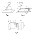
- Fig. 3a shows a laser emitting unit 20 for emission of ultra-short (e.g. femtosecond, particularly ⁇ 600 fs) laser pulses 22 with defined beam profile according to the invention.
- the unit 20 is designed so that an orientation of an emitted laser beam 21 can be varied in defined manner.
- the beam 21 can be moved over a surface of a substrate 1 to be processed according to a defined pattern, particularly along a defined processing or cutting path.
- the emitting unit 20 e.g. comprises a scanning head.
- the emitting unit 20 provides the laser beam 20 with an asymmetric beam shape, i.e. a cross sectional area which is defined by a cross section through the laser beam 20 orthogonal to its propagation direction in the focal point is of asymmetric shape, wherein a length of an axis corresponding to a main extension of the asymmetric shape is greater than a length of a different axis corresponding to a minor extension of the asymmetric shape.
- the laser beam 21 is emitted with constant direction from the laser source 20, wherein a table 19, which carries the substrate 1, is provided and the table 19 is movable in x- and y-directions and/or rotatable relative to the laser source 20.
- processing according to a given processing path is enabled by correspondingly moving the sample 1 (and thus defining the scanning speed) while emitting laser pulses with defined repetition frequency and orientation of the beam profile.
- the distance between the laser-emitting-point and the table 19 is adjustable by either moving the laser source 20 or the table 19 (or both) along the z-axis.
- the repetition rate and the scanning speed preferably are adapted so that the distance between two successive laser pulses 22 on the surface (i.e. the distance between the centres of these pulses on the surface) or in the focal plane, which is located between the upper and the bottom surface of the substrate 1, corresponds to an average length of the lengths of the major micro-cracks in the material (transparent or semi-transparent materials like types of glass), which are effected by these laser pulses.
- the length of a major micro-crack which is caused by such a laser pulse, here basically is of about 5-10 times the length of the respective main axis of the cross sectional area - of the asymmetric cross sections of the pulses - (for better illustration, the laser spots here are illustrated in oversized manner compared to caused micro-cracks), wherein the cross sectional area is defined by the full width half maximum (FWHM) value with respect to the intensity of the laser pulse at the beam centre (of course, the cross sectional area may be defined based on other approaches known from prior art which allow to define the extend of the beam profile).
- the length of an effected major micro-crack depends on several factors like pulse energy, pulse duration, number of applied pulses at one identical point on the material and material properties.
- the length of a major micro-crack basically corresponds to a multiple of the length of the respective main extension axis.
- the caused major micro-cracks by such an emitted series of laser pulses can be applied contiguous so that there is no space in between the respectively effected major micro-cracks (on the surface of the material) by placing the laser spots with respective (corresponding to the ratio of the lengths of the major micro-cracks and the main extension axes) distance.
- the laser pulses 22 may be placed with a defined space between their cross sectional areas and between the effected major micro-cracks on the surface 2.
- a precise and well defined fracture of the material along the predefined processing path could still be provide as the material also cracks between the effected major micro-cracks according to a direct connection line from major micro-crack to major micro-crack.
- the material may be a kind of visually transparent or semi-transparent (at least with respect to a wavelength-region of about 1040 nm) material (e.g. "Xensation" glass) with a thickness of 0.7 mm and the laser source 20 is operated with an average power of 60 mW, wherein each pulse has energy of 24 ⁇ J and wavelength of 1040 nm, and a repetition rate of 2 kHz.
- a scanning speed of 100 mm/s can be reached by effecting micro-cracks with a lateral length of about 50 ⁇ m, wherein the effected micro-cracks propagate through the entire thickness of the material and thus, a clean cut is provided.
- a processing speed of about 10 m/s can be realised.
- a subset of laser pulses (burst, see e.g. fig. 6 ) may be applied for every cutting point particularly if material of greater thickness is to be cut.
- Fig. 4a shows a schematic representation of laser cutting of a curvilinear structure according to the invention.
- a series of laser pulses 22 is applied on the material 1 along a designated curvilinear processing path 25 (as the pulses of the series of laser pulses comprise identical properties except of the orientations of their cross sectional areas, only one of the pulses 22 is referenced by number in place of the rest of the shown pulses).
- the laser pulses 22 are set so that a defined distance between the defined cross sectional areas of each pulse 22 is present.
- the cross sectional area may be defined by a distance to the beam centre at a peak power decrease to 1/e 2 of the peak power.
- each pulse 22 causes a micro-crack in the material 1 the extension of which (regarding the lateral length of the crack) is larger than the length of the major axis of the respective cross sectional area at the focal point.
- a focal plane is defined between a first 2 (facing the laser source) and a second 3 surface (opposite to the first surface 2) of the material 1, wherein the laser pulses 22 are emitted with respective focal points which all lie in such common focal plane.
- each pulse 22 generates a kind of channel 23 throughout the entire material 1 in z-direction.
- the laser pulses 22 impinge according to a direction orthogonal to the first surface 2 of the material 1 (i.e. in z-direction).
- Fig. 4b shows a schematic representation of a top view on the material (first surface 2) as processed similar to as shown in fig. 4a .
- the pulses 22 are applied with such defined relative distance that the generated major micro-cracks 24 basically engage into each other and that one continuous edge is built by the generated major micro-cracks 24 thereby.
- the orientations of the major micro-defects 24 follow the required processing direction.
- the major axis of each respective laser pulse 22 is set so that it is at least parallel to a tangent to the processing path 25 in a respective processing point 26 of the path 25, wherein each laser pulse 22 is assigned to a defined processing point 26.
- any contour can be cut out of the material 1 by using the principle of rotation of the beam profile according to the course of the processing path 25.
- the cutting edge emerges from the series of induced major micro-cracks 24, wherein laser parameters (e.g. pulse energy, repetition rate, pulse duration and shape of the laser pulses) and the properties of the material 1 to be processed (e.g. transparency, thickness and hardness) define the cutting quality and the cutting speed.
- laser parameters e.g. pulse energy, repetition rate, pulse duration and shape of the laser pulses
- properties of the material 1 to be processed e.g. transparency, thickness and hardness
- the material 1 to be cut is thicker than the length of the major micro-crack which is effected in the material 1 along the z-direction by application of one single laser pulse 22, more than one laser pulse 22 can be emitted for each processing point 26 or the pulse energy can be increased in order to provide a micro-crack 24 which penetrates through the whole material 1. This can be done by repeated scanning of the same processing path and/or by applying a laser burst for each processing point.
- a sub-series of laser pulses 22 (burst, see e.g. fig. 6 ) is emitted for each processing point 26 with defined repetition frequency so that a set of laser pulses impinges on a defined point at the material 1 and the micro-crack emerging from that point is enlarged due to the number of burst pulses applied at that point.
- the micro-crack 22 particularly grows laterally along the surface of the material and/or orthogonally to the surface into the material 1 (z-direction).
- the laser pulses 22 are applied so that they impinge on the processing points 26 the pulses are assigned to. As shown here for better clearness, the laser pulses 22 are applied with defined offset to the path 25 and to respective processing points 26 along the path 25.
- the laser properties can be adapted while cutting a contour along the processing path 25.
- regions of the processing path 25 which comprise basically linear cutting parts higher pulse energy could be used for effecting micro-cracks with greater lateral lengths, wherein the pulse energy could be reduced when cutting along a curve for providing micro-cracks with smaller size and thus to more precisely generate a curvilinear contour there.
- the cutting speed and/or the pulse repetition rate would be adapted as well.
- the pulses may be emitted along the defined processing path so that a defined and basically constant amount of energy is brought into the material per unit of length of the processing path or per unit of area (or volume) of the material.
- figs. 5a-e show the dependency of that lateral size on the number of emitted pulses according to the invention.
- the pulses are of pulse durations in the femtosecond region and are applied with a time lag between two successive pulses (burst frequency) of about 13 ns.
- the processed material is formed by a chemically strengthened glass.
- Fig. 5a schematically illustrates the effected major micro-crack 24 on application of one single pulse.
- the length of that micro-crack 24 particularly is about 19 ⁇ m.
- Fig. 5b shows the caused micro-defect 24 with impinging of two pulses at the same point on the material, wherein the length of the micro-defect increases by about 70 %, particularly to up to approximately 32 ⁇ m.
- the size of the micro-crack 24 effected thereby would be about 236 % of the size of the micro-crack by one single pulse (about 45 ⁇ m) as shown in fig. 5c .
- micro-crack size of about 278 % of the initial micro-crack (about 53 ⁇ m) as shown in fig. 5d and the application of more than four pulses, i.e. of multiple pulses, would effect a micro-crack 24 - according to the shown example - with a length of at least 56 ⁇ m as illustrated in fig. 5e .
- the total energy brought into one single (processing) point of the material does not depend on the number of applied pulses but is the same for e.g. three and five generated burst pulses.
- the pulse energy of the single pulse according to fig. 5a corresponds to the sum of pulse energies of the two pulses applied in context of fig. 5b .
- the axial size (z-direction) of the micro-cracks caused by the above use of a burst of pulses e.g. the axial length of a micro-crack increases by application of four pulses by a factor of about "3" compared with the axial length of a micro-crack caused by one single pulse.
- the use of a burst of laser pulses leads to a wider range of material to be processable (i.e. which can be cut precisely) with the method according to the invention, particularly regarding the possible thicknesses of the material. Furthermore, as the lateral micro-crack size also increases distinctly, a higher cutting speed could be reached as well.
- the properties of the pulses within one burst particularly are adapted according to the kind (properties) of material to be processed.
- the time period from pulse to pulse (time lag between two successive pulses) is set so that it basically corresponds to or is smaller than the stress relaxation time of the material.
- the time between the pulses of the burst thus should be equal or smaller than the respective stress relaxation time of the material.
- stress relaxation time of chemical strengthened glass is in the region of about 10 - 20 ns and thus the pulses of the burst can be applied with a time lag between two successive pulses of about 13 ns.
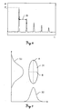
- Fig. 6 shows an embodiment of a power profile of a burst of laser pulses being applied for processing of material in context of the present invention.
- five laser pulses are generated within the respective burst, wherein the number of laser pulses within the burst can vary as to processing requirements.
- the pulses within the burst are generated with a defined pulse-to-pulse time delay (lag) ⁇ t, which e.g. is of about 13 ns.
- the initial pulse of the burst comprises a particular pulse power P 1 (and respective pulse energy E 1 ), wherein successive pulses in the burst are generated comprising successively decreasing pulse energies.
- the energy from pulse to pulse decreases exponentially.
- Fig. 7 shows a measurement of an elliptical beam profile used with the present invention.
- a cross section 31 of a laser beam is shown, which beam is used in form of a laser pulse with defined pulse duration for material processing according to the invention (pulse duration typically is defined based on a FWHM value of the pulse).
- the beam profile i.e. the cross sectional area 31, is of elliptical shape with a major axis A and a minor axis B, wherein the length of the major axis A is about 2.2 times greater than the length of the minor axis B.
- Such ellipticity provides the creation of defined basically linear defects (herein called "major micro-cracks”) in e.g. glassy materials and, generally, in transparent materials.
- the ratio between the length of the major axis relative to the length of the minor axis is of about 1.5 : 1, 2 : 1, 3 : 1 or even >3 : 1.
- the ratio between the major axis and the minor axis is preferably chosen as to the material to be processed and the optimum regarding the emerging micro-crack size and cutting speed.
- the intensity distribution of the beam profile along the major A and the minor B axis as measured with such an elliptical beam is shown.
- the curve 32 depicts the intensity distribution of the laser radiation in the course of the minor axis B and the curve 33 depicts the intensity distribution of the laser radiation in the course of the major axis A.
- the distributions 32,33 significantly differ from each other with view to their widths (e.g. full widths at half heights), which is a measure for the ellipticity of the beam profile of a respective laser pulse.
- a cross section of preferably a Gaussian laser beam as shown here is only a schematic representation of the real intensity distribution over the entire laser beam and that the shape of a laser pulse is depicted by a border line along a defined peak power decrease with respect to the maximum value in the centre of the beam cross section.
- the full width at half height/maximum (FWHH) value or a decrease to 1/e 2 of the peak power is used for illustrating the shapes (and size) of laser pulses.
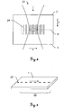
- Fig. 8 shows an interaction between a transparent material to be processed and an ultra-short laser pulse 22 with a cross sectional area in its focal point, the focal plane 4 respectively, of elliptical shape.
- the laser pulse 22 is directed orthogonally to the first surface 2 of the transparent material, i.e. that surface which faces the point of laser emitting, transmits the first surface 2 and interacts with the material basically around the focal plane 4. Due to the high pulse energy (e.g. as discussed above), the ultra-short pulse duration of less than 100 ps and the ellipticity of the beam profile of at least 2 . 1 a major micro-crack 24 is effected within the material.
- Fig. 9 shows a specific method of laser cutting of transparent material, like chemically strengthen glass, according to the invention ("kick method").
- a first series of elliptical laser pulses 22' is emitted to the material 1 along a defined, in particular curvilinear (not shown here), processing path, wherein the pulses are emitted so that effected major micro-cracks have significant distances between each other and thus, the fracture of the material does not occur after having processed the first series of pulses 22'.
- At least one further laser pulse 22" is directed at one of the ends of or at a defined point along the processed processing path and initiates fracture of the material 1.
- the pulse is particularly emitted so that at least one of the already caused major micro-cracks is enlarged by the additional pulse 22" and thus pushes the break of the material 1 along the processing path.
- the further laser pulse 22" is generated with use of different laser parameters, e.g. the further pulse 22" comprises higher pulse energy or a different ratio of its main extension axis relative to its minor extension axis.
- At least one further initiating laser pulse 22" is emitted at the material 1 with defined reference to the processing path so that an interaction of the initiating laser pulse 22" with the material 1 initiates a fracture of the material 1 along the processing path.
Landscapes
- Engineering & Computer Science (AREA)
- Physics & Mathematics (AREA)
- Optics & Photonics (AREA)
- Plasma & Fusion (AREA)
- Mechanical Engineering (AREA)
- Chemical & Material Sciences (AREA)
- Organic Chemistry (AREA)
- Materials Engineering (AREA)
- Chemical Kinetics & Catalysis (AREA)
- General Chemical & Material Sciences (AREA)
- Oil, Petroleum & Natural Gas (AREA)
- Laser Beam Processing (AREA)
- Re-Forming, After-Treatment, Cutting And Transporting Of Glass Products (AREA)
Description
- The present invention generally pertains to a method for processing of material by use of a pulsed laser, and a laser system, wherein micro-cracks with defined orientation are effected in the material by applying laser beam pulses with elongated spatial distribution of laser power across its beam cross section so that precise cutting of the material along a designated processing path is enabled with high speed.
-
DE102012110971A1 discloses a method and a system according to preambles ofclaims - Established mechanical methods for machining of fragile materials such as saw cutting and scribing often cannot satisfy the industrial needs or requires extensive post processing to meet the needs in terms of quality and throughput. Nowadays, lasers are increasingly used for machining of different types of materials. Laser cutting processes such as melting, vaporization and fusion cutting are used for cutting of ductile materials like metals and polymers. These methods are not appropriate for cutting of transparent or semi-transparent materials to meet required high quality and cutting speed standards.
- As for instance known from D. Helie and R. Vallee, "Micromashining of Thin Glass Plates with a Femtosecond Laser", Proc. of SPIE Vol. 7386, 738639, Photonics North 2009, for such cutting of transparent materials a controlled fracture technique is a well suitable method for machining of those materials.
- When curvilinear and close shaped internal features are needed to be cut a laser direct ablation process can be used. However, the ablation rate, i.e. the processing speed of the direct ablation method, is scaled with the laser average power and normally limited to several mm/s. Besides of slow processing speed the formation of cracks, contamination by ablation debris, collateral damages along cut (heat affected zone) are typical disadvantages of the laser direct ablation processes.
- Application of femtosecond laser filamentation for machining of glass substrate is an interesting alternative to the direct ablation process. An idea of fast cutting of a display glass where the sample is pre-processed using femtosecond laser pulses prior to glass cleaving was proposed by Ahmed et al. (F. Ahmed, M.S. Lee, H. Sekita, "Display Glass Cutting by Femtosecond Laser induced single shot periodic void array", Appl. Phys. A (2008) 93, 189-192). The maximum processing speed achieved in this study was 15 mm/s. The speed has been limited by the minimum distance between voids, because it was not possible to cleave the sample when void period was larger than 10 µm.
-
DE 10 2012 110971 A1 andUS 2012/111310 A1 both teach specific methods for laser processing and approaches of particular beam shaping, e.g. of using elliptically shaped beam for material processing in order to increase processing speeds. - The stress build-up and micro-defects induced by filamentation are known for being used for cutting of thin borosilicate glass substrate and for production of simple 3D parts from different types of glass. However, controlling of the generated cutting edge cannot be realised by this technique, hence the application of above proposed methods for cutting of curvilinear and internal features is not feasible.
- Therefore, it is an object of the present invention to provide an improved processing method for (e.g. transparent or semi-transparent) materials, wherein a more precise processing of the material, particularly in terms of quality of a cutting edge, along a desired processing path with higher processing speed (e.g. > 15 mm/s) is enabled.
- A further object of the invention is to provide a laser cutting method which enables to cut curvilinear or other shape contours in a transparent or semi-transparent material with high precision and speed.
- These objectives are achieved by realising the features of the independent claims. Features which further develop the invention in an alternative or advantageous manner are described in the dependent patent claims.
- The invention relates in one aspect to cutting plates, wafers and/or substrate using formation and controlling of micro defects orientation inside of a transparent material. This can be used for the straight cut as well as for producing of the curvilinear and/or internal closed shape features in the material.
- The invention relates to a method for processing of transparent or semi-transparent (with respect to a wavelength of the pulsed laser) material by use of a pulsed laser, according to
claim 1. - The main physical effect, which allows coupling of laser energy into transparent or semi-transparent material, is nonlinear absorption. Nonlinear absorption allows confinement of the laser energy inside of the material. Application of ultra-short laser pulses makes the nonlinear processes in material such as nonlinear absorption and self-focusing etc. more likely.
- Accordingly, for processing of transparent or semi-transparent material, the respective wavelengths of the emitted laser pulses correspond to a wavelength-transparent or wavelength-semi-transparent range of the material to be processed. In other words, the wavelength of the emitted laser light is adapted according to the transparency or semi-transparency of the material. Typically, the laser pulses are emitted with one common wavelength, e.g. in the near-infrared region for processing of glass.
-
Fig 1 shows a typical defect inside of aglass material 100 induced by application of one femtosecond laser pulse at 1040 nm as known from prior art. The used laser beam here comprises a fully symmetrical circular beam profile. Due to that circular profile the occurring defects consist of a set ofradiant cracks 102 around the generatedchannel 101. The maximum size of such cracks typically is of about 10 µm length. Since controlling the type and the shape of the micro defect inside of glass can not be realised by applying a circular beam profile the inventive method is based on an alternative approach. - According to the invention, each laser pulse is shaped regarding its beam profile so that a cross sectional area, which is defined by a cross section of the laser pulse orthogonal to its propagation direction in the focal point, is of elongated shape (i.e. the beam profile is asymmetric in contrast to a fully symmetrical circular beam) and defines a main extension axis as to its elongated extension. Moreover, one major micro-crack is effected by each laser pulse, the major micro-crack having a lateral extension basically oriented according to the direction of the main extension axis of the cross sectional area of the respective pulse in the focal point. Additionally, each laser pulse is irradiated on the material so that the orientation of its main extension axis in the focal point corresponds to a pre-defined orientation relative to an orientation of a respective tangent to the processing path at the particular processing point.
- In context of the present invention, the cross sectional area particularly is defined by a distance to the centre of the laser beam which corresponds to a decrease of the laser peak power to an half (full width half maximum, FWHM) or to 1/e2 of that power (Gaussian beam profile). Typically, the reference (1/2 or 1/e2) only influences the size but not the shape (ellipticity) of the cross section. Regarding the shape of the laser beam (i.e. of the beam profile of the laser pulse) which effects the desired micro-crack in the material, the cross sectional area as defined above is related to a corresponding cross section through the laser beam in the focal point or the focal plane, respectively.
- It is to be understood that the beam profile not necessarily has to be of a "Gaussian" profile but may alternatively be a "Top-Hat" or "Donut" profile or any other beam profile providing for suitable asymmetry of the cross sectional area.
- Furthermore, in context of the present invention, (full) symmetry of the cross sectional area is understood to be rotationally symmetrical in continuous manner (i.e. independent from a grade of rotation), wherein asymmetry is understood to also be rotational symmetric but only in discrete manner (e.g. by each 180° of rotation). For instance, in sense of the present application, a circle is assumed to be symmetrical wherein an ellipse is assumed to be asymmetrical (= not fully symmetrical). Moreover, a symmetric body is to be understood as being axisymmetric with respect to any axis intersecting the geometric center, wherein a body is asymmetric as soon as symmetry according to one of such axis is not given. Of course, asymmetric shapes not necessarily have to provide any symmetry.
- By above processing method a controlled manipulation of the material is provided by generating micro-defects (micro-cracks) in the material in a defined manner in terms of formation and orientation of the effected defects. Due to the asymmetric laser beam (instead of a symmetric, circular beam) very well defined single major micro-cracks (micro-defects) are obtained (instead of an arbitrary number of radiant cracks). There only emerges one single major micro-crack per initially impinging pulse.
- Of course, there may additionally be effected significantly smaller minor cracks (by interaction of the emitted laser pulse with the material to be processed) the extension axis of which differs from that of the major crack, but as these minor cracks due to their essentially smaller sizes do not contribute to a desired processing of the material, they are considered negligible in context of the present invention.
- Regarding the shape of the cross sectional area of the laser beam, the laser pulses are shaped so that a defined main extension direction is given by the cross sectional area. Thus, the pulses may have kind of elongated shapes like a stripe, particularly a line with little extension relative to the direction of the line, or like a rectangle (wherein - of course - the longer sides of the rectangle define the main extension axis) or like an ellipse with a major axis and a minor axis as described herein below. Furthermore, the cross sectional area may be of any alternative (non geometric) shape which provides one single main elongation direction (axis).
- As the pulse is directed to the surface so that the orientation of the main extension axis is correlated with the orientation of a tangent on the processing path, each major micro-crack effected (caused) thereby also correlates as to its orientation to the orientation of a tangent to the processing path, particularly at the respective processing point.
- The processing path, to which the method according to the invention basically (but not exclusively) is related, is embodied as a curvilinear (curved) processing path.
- Moreover, a major micro-crack which is generated by emitting an asymmetric laser pulse at a transparent or semi-transparent material has - compared to a micro-crack induced by a circular pulse with basically same pulse energy - an increased length.
- Furthermore, in contrast to filamentation approaches known from prior art, a major crack effected by the present method is of significantly greater lateral size than a major axis of its cross sectional area. Filamentation aims to generating accurate channels of diameters in the region of the size of the beam cross section throughout the entire material (in z-direction), wherein the major cracks to be effected in context of the present invention are desired and effected with notable greater lateral extension compared to the beam diameter.
- In particular, on emitting the laser pulses, a distance between the laser system (i.e. a point where the laser beam is emitted by the laser system) and the first surface of the material, which faces the laser system, corresponds to less than or equal to the focal length of the laser beam and a distance between the laser system and the second surface, which second surface is turned away from the laser system, corresponds to more than or equal to the focal length of the laser beam, for providing a well focussed beam e.g. in a defined focal plane.
- Alternatively, the laser pulses are focussed and emitted so that the focal points of the emitted laser pulses lie in different planes within the material. That approach allows processing of e.g. specifically shaped material or of material which comprises defined structures.
- Alternatively, the laser beam is focussed so that the focal point lies above but still near the first surface or below but still near the second surface.
- The laser pulses may preferably be ultra-short laser pulses with pulse durations of < 1ns, particularly < 10 ps or in the femtosecond region.
- In context of the present invention, the material to be processed is in form of a transparent material, particularly glass or sapphire, particularly chemically strengthened glass.
- The above effects and properties provide the further advantage that a lateral propagation of a crack in the material can be controlled and defined with respect to its direction by applying successive laser pulses with defined lateral distance and defined orientation relative to each other. The induced crack propagates basically according to the orientation of a projection of the main extension axis of the elongated cross sectional area in the focal point of a following laser pulse, i.e. in case the laser pulse impinges orthogonally on the surface (the propagation direction of the laser beam is orthogonal to the surface of the material), the crack propagates basically according to the orientation of the main extension axis of the elongated cross sectional area (e.g. of the elliptical beam profile). In addition, the inventive method of controlled formation and controlled orientation of micro-defects inside materials offers the advantage over other laser processing methods, particularly cutting, that cutting can be performed with significant higher speed. This is achieved because the distance between voids used for cutting are defined by the size of micro-defects. As these defects are created with greater lengths, fewer pulses have to be emitted for cutting and thus the cutting speed can be increased correspondingly.
- Furthermore, the method according to the invention provides for precise cutting of a curvilinear contour and of internal closed shape features in transparent or semi-transparent (with respect to the wavelength) material.
- Additionally, a high quality cut is provided, wherein no chipping and no debris along the cutting edge occur, and a processing without or with very small kerf losses is provided. Particularly, no or very less micro-defects are left inside of material after cleaving.
- The above method of laser processing may preferably be realised with a laser system for generating ultra-short laser pulses, i.e. pulses with pulse durations in the femto- or picosecond order, wherein the system has to be embodied in specific manner for performing the method. The system in general may comprise a mode-locked laser generator with e.g. a ytterbium- or neodymium-doped laser medium like ytterbium doped wolframate (e.g. Yb:KYW or Yb:KGW) or neodymium doped vanadate (e.g.Nd:YVO4). Systems of such general configuration are well known for applications of material processing.
- According to the invention, the orientation of the main extension axis of the cross sectional area of each laser pulse is adapted depending on the course of the processing path by a defined rotation of the beam profile. The beam profile is particularly rotated around the centroid of the cross sectional area. Such rotatability of the beam profile provides material processing according also to curvilinear paths, wherein upon a change of the path direction the orientation of the beam profile is adapted accordingly so that applied pulses remain oriented in defined relation to respective tangents (concerning their main extension axes) to the processing path.
- By that, a possibility to control crack propagation is given using an elongated (e.g. elliptical or stripe like shaped) beam. For instance, an elliptical beam is rotated by 15° per step in order to provide processing along a curvilinear path with respective curvature. A change of the orientation of the elliptical beam relatively to the sample to be processed leads to a change in the orientation of the effected micro-cracks inside of the sample, e.g. glass sample. As mentioned above, the direction of micro-crack propagation basically coincides with the direction of the ellipse major axis in the focal point between the surfaces of the material.
- The change of the orientation of the cross section for the laser pulses, i.e. of the beam profiles, for instance is realised by a specific variable arrangement of optical or electro-optical elements (e.g. mirror, prism etc.) and/or by specific adaptations concerning the coupling the laser beam out of the laser system. Such adaptation of the orientation may be provided by a beam defining unit.
- Concerning orienting the main extension axes of the emitted laser pulses, with view to amorphous material like glass, it generally is regardless of how the pulses are oriented relative to the material (as there is no defined structure within the material) for providing a suitable processing of the material. However, as to processing and specifically cutting of crystalline material the orientation of the main axis of the first pulse(s) applied to the material may significantly influence the processing, in particular influences the way of fracturing of the material with respect to laser cutting. In order to provide precise cutting of crystalline structured material, the orientation of the main extension axis of the first emitted pulse is to be set in such manner that the orientation of such main extension axis corresponds to the crystalline structure of the material (i.e. corresponds to an orientation of the crystals in the material). For that, the processing path and/or the orientation of the crystalline material to be processed relative to the laser system may be adapted accordingly.
- With respect to orienting each laser pulse according to the processing path, each laser pulse is emitted with a pre-defined orientation of its main extension axis which (pre-defined orientation) corresponds to an angular deviation from the orientation of the respective tangent (at the processing point) of up to 20°, particularly up to 10°.
- By setting a defined rotational angular deviation from the respective tangent to the processing path, the propagation of a continuous crack in the material can be controlled concerning particular materials like glass (e.g. in case the effected major micro-cracks are not adjoining, but there is a defined gap between the major micro-cracks), i.e. the propagation of the crack (fracture of the material) occurs after a defined time interval after laser processing. For such materials, the crack-propagation is dependent on the described angular deviation. That effect and its controlling can be advantageous with view to cutting of such material, wherein the material initially bursts after completion of an entire processing step.
- Thus, a pre-defined time-delay with respect to crack-propagation in the material can be adjusted by correspondingly setting the angular deviation of the orientation of the main extension axis of the laser pulses relative to the respectively assigned tangent.
- Concerning the locations at which the laser pulses impinge on the surface of the material, the pulses are placed in well defined manner.
- According to the invention, the respective major micro-cracks are effected with lateral lengths significantly larger than the length of the respective main extension along the main extension axis of the cross sectional areas in the focal point, the lateral lengths relate to a length of the respective major micro-cracks in a direction basically parallel to a focal plane, in particular wherein the lateral lengths are in a range of 3-30 times the length of the respective major axes.
- According to a specific embodiment of the invention, the laser pulses are emitted so that a lateral distance on the surface or in a plane relative to the first surface and/or with reference to the focal points between at least two of the laser pulses, which are successively emitted, corresponds to an average of the lateral lengths of the major micro-cracks caused thereby.
- Thus, in above context, in case the length of the effected major micro-crack by one laser pulse corresponds to 3-30 times the distance (in the focal plane) from the beam centre to a point along the main extension axis of the cross section at which the power of the laser e.g. is 1/e2 of the peak power and the distance between two of such pulses basically is the average of the lengths of the effected major micro-cracks, the effected major micro-cracks are touching each other (are adjoining). With other words, as an example, the length of the main extension axis of a pulse in the focal point is in the range of 2-3 µm and the effected major micro-crack has a lateral (parallel to the first surfaces of the material and/or to the focal plane) length in the rage of 10-60 µm, the laser pulses are applied with a distance between each others corresponding to a respective value of the rage of 10-60 µm.
- Preferably, the laser pulses are directed so that the effected major micro-cracks are laterally touching or nearly touching each other in order to provide a precise processing or cutting of the material. As the micro-cracks typically comprise lengths greater than the length of the main axes of the cross sections of respective pulses, the distance between the pulses on the surface is chosen correspondingly bigger.
- According to a respective embodiment of the invention, the laser pulses are emitted so that the lateral distance between at least two of the laser pulses (with reference to their focal points or on the first surface, respectively), which are successively emitted, is bigger than the average of the lengths of the main extensions, particularly major axes, of respective cross sectional areas of these pulses in the focal points. By that, respective major micro-cracks are created with a defined spacing in between or respective major micro-cracks are adjoining (basically no distance between the micro-cracks and also basically no overlapping). Furthermore, the major micro-crack effected by a first of the successive laser pulses is extended due to the major micro-crack induced by a second of the successive laser pulses.
- In particular, according to the invention, the laser pulses are emitted so that successively emitted laser pulses impinge on the surface with a relative lateral distance as described above. Consequently, (only) one single laser pulse is directed to each respective processing point, wherein a defined distance to a preceding and to a following laser pulse exists.
- Preferably, a distance of successive (neighbouring) processing points on the processing path corresponds to a lateral distance as outlined above. Thus, the distance between two processing points may correspond to an average of the lateral lengths of the major micro-cracks which are caused by pulses applied at these points.
- According to a preferred embodiment, at least one of the laser pulses is shaped so that its cross sectional area is of elliptical shape (in its focal point) and the main extension axis is defined by (the direction of) the major axis of the elliptical cross sectional area, i.e. the major axis corresponds to the main extension axis.
- For effecting the linear major micro-cracks with laser pulses of elliptical pulse profile - according to the invention - the laser beam (a laser pulse respectively) is configured (shaped) so that the relation of the length of the major axis to the length of the minor axis of the (elliptical) cross sectional area is at least 1.1 : 1 or 1.2 : 1.
- Glass cutting according to the method of the invention for example shows reliable good results regarding cutting quality and processing speed, wherein an ellipticity of the beam profile of 2.18 is used, i.e. the ratio of the length of the major axes to the length of the minor axis is 2.18 : 1. Therefore, according to a specific embodiment of the invention, the relation of the length of the major axis to the length of the minor axis of the cross sectional area is at least 2 : 1, particularly is in the range of 2 : 1 to 3 : 1.
- With respect to suitable processing regarding a specific material to be processed, laser parameters particularly are adapted to the type of material. As to an embodiment of the invention, the properties of the laser pulses, in particular the lengths of the main extension axes (e.g. the ellipticity of a Gaussian laser beam profile), pulse repetition rate, pulse durations and/or pulse energies, are adjusted regarding the properties of the material to be processed, in particular regarding a chemical composition and/or a thickness of the material, so that each laser pulse effects a respective major micro-crack with designated lateral length and/or with designated extension in a direction normal to the focal plane, in particular through the entire material.
- By providing such individually adapted laser pulses, major micro-cracks with defined lengths can be produced in the material and processing, e.g. cutting, of the material can be performed in a more reliable and optimised way.
- According to a specific arrangement of the invention, a single laser pulse of the series of laser pulses, which is directed to the material, effects a major micro-crack with a lateral length of at least 3 µm, particularly at least 10 µm, particularly wherein the single laser pulse comprises a pulse energy of about 40 µJ, a pulse duration in the femtosecond order and the material is transparent or semi-transparent, in particular is made of chemically strengthened (visually transparent) glass, unstrengthened glass or sapphire, e.g. a glass sheet used for displays of mobile phones.
- According to a further arrangement of the invention, a single laser pulse of the series of laser pulses, which is directed to the material, causes a micro-crack with an extension as to the direction normal to the surface of the material in a range of 10 to 50 µm, particularly in a range of 10 to 30 µm.
- Concerning material processing is in form of cutting the material, such cutting of the material - according to the invention - is performed by inducing successive major micro-cracks along the processing path in adjoining manner, wherein a cutting edge is defined by a course of the successive major micro-cracks in the material.
- Particularly, the cutting of the material is performed with a lateral cutting speed regarding the surface of the material in a range of 0.2 to 10 m/s, in particular 0.2 - 3 m/s, the cutting speed depends at least on the asymmetry of the cross sectional area, particularly on the ratio of the lengths of the major axis and the minor axis of the cross sectional area, on the lateral (and/or normal) length of the effected micro-cracks (micro-defects), on the pulse energy, on the pulse duration and on a pulse repetition rate. The higher the pulse energies the bigger the effected major micro-cracks may be and the lesser the number of laser pulses to be emitted for cutting along the path is. Additionally, if the pulse repetition rate is increased the cutting speed could be increased, as thus the distance of impinging pulses could be maintained anyway.
- Concerning the cutting of relatively thick material, the cutting of the material may be performed by repeated emitting of the laser pulses along the processing path, wherein the major micro-cracks effected by firstly directing the laser pulses along the processing path propagate at least in the direction normal to the focal plane when directing the laser pulses along the processing path for a second time or for further times, in particular wherein the position of the focal point is adapted for each directing of the laser pulses along the processing path. By doing so, a defined number of laser pulses (according to the number of repetitions of the processing path) are applied at each processing point and an initially effected micro-crack can be enlarged by each additional pulse applied.
- In particular, each such scan is performed at a different distance between the laser system and the material sample for providing the series of pulses to be applied with adapted focal distance. Alternatively, the focal distance is adapted by adjusting respective optical elements. E.g. when scanning the path for the second time the distance is increased so that the focal point of the laser beam no longer is in the region of the second surface (which is turned away from the point of laser emitting) of the material but lies rather "inside" of the sample (closer to the first surface (which faces the point of laser emitting).
- As a particular example for such cutting, "Gorilla" Glass (by Corning Inc., USA) of a thickness of about 0.55 mm can precisely and reliably be cut with following cutting parameters. The ultra-short laser pulses comprise an elliptical shape with an ellipticity of about 2.18. The pulse energy is 34 µJ and the pulses are emitted with a frequency (repetition rate) of 3.3 kHz. Thus, a scanning speed of about 100 mm/s is reached, wherein the cutting path is to be processed for four times and thus an effective cutting speed of 25 mm/s results. Such cutting is performed using an average laser power of 140 mW. By increasing the power to 8 W, and increasing repetition rate to 200 kHz, a cutting speed of 1.5 m/s could be reached.
- For a cutting process as exemplarily outlined above, preferably bursts of laser pulses (multiple laser pulses successively applied at one processing point instead of one single pulse) are used in order to provide larger micro-cracks with each scan.
- Thus, with view to optimised (fast and precise) material processing - according to the invention - a burst of laser pulses with a defined burst energy (i.e. the sum of pulses of the burst comprises a defined total burst energy) can be generated, the burst of laser pulses being directed at a designated point of the material, particularly at a processing point, wherein a defined inducement and propagation of a respective micro-crack in the material is provided, in particular wherein the burst energy is of at least 10 µJ.
- In particular, the laser pulses of the burst are generated with a pulse-to-pulse time lag in a range of 1 to 100 ns, in particular in a range of 10 to 20 ns. Such time lag is preferably chosen in dependency on a stress relaxation time of the material. I.e. if a material with differing relaxation properties is to be processed, the pulse-to-pulse time lag may be adapted accordingly.
- As a big advantage, such a burst may cause a crack in the material with an extension as to the direction normal to the surface of the material in a range of 50 to 150 µm, particularly in a range of 60 to 100 µm. Of course, the size of the effected crack depends on the used material and the laser configuration.
- According to a specific embodiment of the invention the laser pulses of the burst are - additionally or alternatively - generated comprising a defined power profile. The power profile is defined by an exponential decay of pulse energies of the pulses of the laser burst (i.e. pulses within the burst), in particular wherein the energy of an initial burst pulse is in a range of 15% to 30%, in particular in a range of 20% to 25%, of the burst energy, or an exponential increase of pulse energies of the pulses of the laser burst, or constant pulse energies within the burst.
- A burst of above may comprise at least five sub-pulses, which are generated with defined pulse-to-pulse time lag, wherein the time lag may vary or be constant for all pulses. The first emitted pulse of the sub-pulses may comprise about 23% of the entire burst energy and successive pulses may comprise successively deceasing energies.
- Regarding the method according to the invention in general, the laser pulses may particularly be directed (emitted) so that the centroid of the cross sectional area of each laser pulse is located on the surface or inside of the material depending on the designated processing point, in particular wherein the laser pulses are directed so that the centroid of each cross sectional area lies on the processing path or corresponds to the respective processing point.
- The invention also relates to a laser system for processing of transparent or semi-transparent material regarding a wavelength of the laser (in sense of the used laser wavelength), in particular fragile material, according to
claim 12. - According to the invention, the laser source is designed in a manner such that each laser pulse is shapeable regarding its beam profile so that a cross sectional area, which is defined by a cross section of the laser pulse in its focal point orthogonal to its propagation direction, is of elongated shape (i.e. the beam profile is of asymmetric, e.g. elliptical, shape) and defines a main extension axis as to its elongated extension. Thereby, one major micro-crack is effectable by each laser pulse, the major micro-crack having a lateral extension basically oriented according to the direction of the main extension axis of the cross sectional area of the respective pulse in the focal point. Furthermore, the system provides a processing function which is designed to control the beam defining unit, and particularly the laser source, in a manner such that each laser pulse is emittable so that the orientation of its main extension axis in the focal point corresponds to a pre-defined orientation relative to an orientation of a respective tangent to the processing path at the assigned processing point.
- The laser system particularly comprises a controlling unit for controlling the defining unit and the laser source according to the above features of beam shaping and placement of laser pulses.
- According to particular embodiments of the laser system, the processing function is designed in a manner such that an above-described method is performed on execution of the processing function.
- In particular, the laser system comprises a table which is designed to be movable in at least two directions (x- and y-direction) relative to the laser source and/or to the beam defining unit, the table providing desired displacement of a sample to be processed, in particular wherein the table is moveable so that the laser pulses are directed to the material with defined reference to the respective processing points.
- The method and the devices according to the invention are described or explained in more detail below, purely by way of example, with reference to working examples shown schematically in the drawings. Specifically,
- fig. 1
- shows a cross cut through a sample processed with a circular laser pulse as known from prior art;
- fig. 2
- shows a cross cut through a transparent material processed with laser pulses of elliptical beam profiles according to the invention;
- figs. 3a-b
- show laser emitting units for emission of femtosecond laser pulses with defined beam profile on a material to be processed according to the invention;
- figs. 4a-b
- show schematic representations of laser cutting of curvilinear structures according to the invention;
- figs. 5a-e
- show the dependency of the lateral size on the number of emitted elliptical pulses according to the invention;
- fig. 6
- shows an embodiment according to the invention of a power profile of a burst of laser pulses;
- fig. 7
- shows a measurement of a beam profile used with the present invention;
- fig. 8
- shows an interaction of an invention-like shaped laser pulse with a transparent material and the major crack effected thereby; and
- fig. 9
- shows a specific method of laser cutting of transparent material according to the invention ("kick method").
-
Fig. 2 shows a cross cut through atransparent material 1, e.g. chemically strengthened glass like "Xensation" Aluminosilicate Glass (by Schott AG, Germany) or "Gorilla" Glass (by Corning Inc., USA), wherein an ultra-short laser pulse with an elliptical beam profile 11a, i.e. the shape of thecross sectional 11 of the laser pulse is elliptical, impinges orthogonally on the focal plane within thematerial 1. As an effect of the energy brought into thematerial 1 by the laser pulse in defined manner regarding the beam profile, particularly regarding pulse duration and/or pulse energy, one single major elongated micro-defect 12 (micro-crack 12) is caused in thematerial 1. - Alternatively, the material to be processed is formed by a conductive and transparent oxide film which is used with solar cells or flat panel displays, e.g. an oxide film of ZnO with defined thickness.
- As can be seen from
fig. 2 , the lateral extension of the micro-crack 12 is significantly greater than the length of the main extension axis (here: major axis) of the crosssectional area 11. Such micro-crack 12 occurs by applying an ultra-short laser pulse with a suitable asymmetric beam profile, e.g. elliptical beam profile, in sense of the present invention, particularly by applying more than one pulse at one single point on thematerial 1. - It is to be understood, that a micro-crack caused by application of a laser pulse of asymmetric (elliptical) beam profile according to the invention in the end is exactly defined, particularly regarding its size, due to an interaction of material and laser properties.
- In context of above embodiments of the invention, the size of the cross sectional area of the laser beam at the focal point may be defined by a distance to the centre of the laser beam (channel 15) which e.g. corresponds to a decrease of the laser peak power to 1/e2 of that power (particularly for Gaussian beam profiles).
-
Fig. 3a shows alaser emitting unit 20 for emission of ultra-short (e.g. femtosecond, particularly < 600 fs)laser pulses 22 with defined beam profile according to the invention. Theunit 20 is designed so that an orientation of an emittedlaser beam 21 can be varied in defined manner. Thus, thebeam 21 can be moved over a surface of asubstrate 1 to be processed according to a defined pattern, particularly along a defined processing or cutting path. For providing such movement of the laser beam the emittingunit 20 e.g. comprises a scanning head. - Moreover, the emitting
unit 20 provides thelaser beam 20 with an asymmetric beam shape, i.e. a cross sectional area which is defined by a cross section through thelaser beam 20 orthogonal to its propagation direction in the focal point is of asymmetric shape, wherein a length of an axis corresponding to a main extension of the asymmetric shape is greater than a length of a different axis corresponding to a minor extension of the asymmetric shape. By moving the laser beam over the surface with defined processing speed and emitting suchasymmetric laser pulses 22 with a pre-defined pulse repetition rate, a number of thelaser pulses 22 can be applied on the surface, wherein thepulses 22 impinge with defined lateral distance relative to each other on the surface. - Alternatively, as shown in
fig. 3b , thelaser beam 21 is emitted with constant direction from thelaser source 20, wherein a table 19, which carries thesubstrate 1, is provided and the table 19 is movable in x- and y-directions and/or rotatable relative to thelaser source 20. Thus, processing according to a given processing path is enabled by correspondingly moving the sample 1 (and thus defining the scanning speed) while emitting laser pulses with defined repetition frequency and orientation of the beam profile. Particularly, the distance between the laser-emitting-point and the table 19 is adjustable by either moving thelaser source 20 or the table 19 (or both) along the z-axis. - Particularly, a combination of moving the
laser beam 21 and moving thesample 1 could be applied. - The repetition rate and the scanning speed preferably are adapted so that the distance between two
successive laser pulses 22 on the surface (i.e. the distance between the centres of these pulses on the surface) or in the focal plane, which is located between the upper and the bottom surface of thesubstrate 1, corresponds to an average length of the lengths of the major micro-cracks in the material (transparent or semi-transparent materials like types of glass), which are effected by these laser pulses. - The length of a major micro-crack, which is caused by such a laser pulse, here basically is of about 5-10 times the length of the respective main axis of the cross sectional area - of the asymmetric cross sections of the pulses - (for better illustration, the laser spots here are illustrated in oversized manner compared to caused micro-cracks), wherein the cross sectional area is defined by the full width half maximum (FWHM) value with respect to the intensity of the laser pulse at the beam centre (of course, the cross sectional area may be defined based on other approaches known from prior art which allow to define the extend of the beam profile). The length of an effected major micro-crack depends on several factors like pulse energy, pulse duration, number of applied pulses at one identical point on the material and material properties.
- The length of a major micro-crack basically corresponds to a multiple of the length of the respective main extension axis. The caused major micro-cracks by such an emitted series of laser pulses can be applied contiguous so that there is no space in between the respectively effected major micro-cracks (on the surface of the material) by placing the laser spots with respective (corresponding to the ratio of the lengths of the major micro-cracks and the main extension axes) distance. By use of such a processing approach a continuous cutting of the material is provided, wherein a respective cutting edge is defined by the propagation of the crack with each emitted
laser pulse 22. - Particularly, depending on the material to be processed (particularly to be cut) the
laser pulses 22 may be placed with a defined space between their cross sectional areas and between the effected major micro-cracks on thesurface 2. A precise and well defined fracture of the material along the predefined processing path could still be provide as the material also cracks between the effected major micro-cracks according to a direct connection line from major micro-crack to major micro-crack. - By optimising the distance between two successively impinging
pulses 22 on thesample 1, i.e. choosing the largest distance wherein still precise processing or cutting of the material is possible by still meeting demanded requirements, e.g. requirements with view to precision and cutting quality, an optimised (high) processing (cutting) speed can be reached. - As one example, the material may be a kind of visually transparent or semi-transparent (at least with respect to a wavelength-region of about 1040 nm) material (e.g. "Xensation" glass) with a thickness of 0.7 mm and the
laser source 20 is operated with an average power of 60 mW, wherein each pulse has energy of 24 µJ and wavelength of 1040 nm, and a repetition rate of 2 kHz. With such configuration a scanning speed of 100 mm/s can be reached by effecting micro-cracks with a lateral length of about 50 µm, wherein the effected micro-cracks propagate through the entire thickness of the material and thus, a clean cut is provided. With increasing the power of thelaser 20 up to 8 W or higher, a processing speed of about 10 m/s can be realised. For such processing, preferably, a subset of laser pulses (burst, see e.g.fig. 6 ) may be applied for every cutting point particularly if material of greater thickness is to be cut. -
Fig. 4a shows a schematic representation of laser cutting of a curvilinear structure according to the invention. A series oflaser pulses 22 is applied on thematerial 1 along a designated curvilinear processing path 25 (as the pulses of the series of laser pulses comprise identical properties except of the orientations of their cross sectional areas, only one of thepulses 22 is referenced by number in place of the rest of the shown pulses). Thelaser pulses 22 are set so that a defined distance between the defined cross sectional areas of eachpulse 22 is present. The cross sectional area may be defined by a distance to the beam centre at a peak power decrease to 1/e2 of the peak power. - Here, each
pulse 22 causes a micro-crack in thematerial 1 the extension of which (regarding the lateral length of the crack) is larger than the length of the major axis of the respective cross sectional area at the focal point. A focal plane is defined between a first 2 (facing the laser source) and a second 3 surface (opposite to the first surface 2) of thematerial 1, wherein thelaser pulses 22 are emitted with respective focal points which all lie in such common focal plane. - As shown in the example according to
fig. 4a , eachpulse 22 generates a kind ofchannel 23 throughout theentire material 1 in z-direction. Of course, it is to be understood that it at least depends on the thickness of thematerial 1 if thechannel 23 penetrates theentire material 1. Thelaser pulses 22 impinge according to a direction orthogonal to thefirst surface 2 of the material 1 (i.e. in z-direction). -
Fig. 4b shows a schematic representation of a top view on the material (first surface 2) as processed similar to as shown infig. 4a . Thepulses 22 are applied with such defined relative distance that the generatedmajor micro-cracks 24 basically engage into each other and that one continuous edge is built by the generatedmajor micro-cracks 24 thereby. - According to the invention, by a rotation of the elliptical beam the orientations of the major micro-defects 24 (cracks) follow the required processing direction. For that, the orientations of the major axes of the elliptical cross sections (= main extension axes) of the
laser pulses 22 are adapted (changed) for to provide a direction of these axes parallel to respective tangents to theprocessing path 25 or to provide these axes to even be coaxial with such tangents. In other words, the major axis of eachrespective laser pulse 22 is set so that it is at least parallel to a tangent to theprocessing path 25 in arespective processing point 26 of thepath 25, wherein eachlaser pulse 22 is assigned to a definedprocessing point 26. - Thus, according to the invention, any contour can be cut out of the
material 1 by using the principle of rotation of the beam profile according to the course of theprocessing path 25. The cutting edge emerges from the series of inducedmajor micro-cracks 24, wherein laser parameters (e.g. pulse energy, repetition rate, pulse duration and shape of the laser pulses) and the properties of thematerial 1 to be processed (e.g. transparency, thickness and hardness) define the cutting quality and the cutting speed. - For instance, in case the
material 1 to be cut is thicker than the length of the major micro-crack which is effected in thematerial 1 along the z-direction by application of onesingle laser pulse 22, more than onelaser pulse 22 can be emitted for eachprocessing point 26 or the pulse energy can be increased in order to provide a micro-crack 24 which penetrates through thewhole material 1. This can be done by repeated scanning of the same processing path and/or by applying a laser burst for each processing point. - According to a specific embodiment of the invention, a sub-series of laser pulses 22 (burst, see e.g.
fig. 6 ) is emitted for eachprocessing point 26 with defined repetition frequency so that a set of laser pulses impinges on a defined point at thematerial 1 and the micro-crack emerging from that point is enlarged due to the number of burst pulses applied at that point. By that, the micro-crack 22 particularly grows laterally along the surface of the material and/or orthogonally to the surface into the material 1 (z-direction). - Particularly, the
laser pulses 22 are applied so that they impinge on the processing points 26 the pulses are assigned to. As shown here for better clearness, thelaser pulses 22 are applied with defined offset to thepath 25 and to respective processing points 26 along thepath 25. - The laser properties can be adapted while cutting a contour along the
processing path 25. For regions of theprocessing path 25 which comprise basically linear cutting parts higher pulse energy could be used for effecting micro-cracks with greater lateral lengths, wherein the pulse energy could be reduced when cutting along a curve for providing micro-cracks with smaller size and thus to more precisely generate a curvilinear contour there. Correspondingly, the cutting speed and/or the pulse repetition rate would be adapted as well. - Alternatively or additionally, the pulses may be emitted along the defined processing path so that a defined and basically constant amount of energy is brought into the material per unit of length of the processing path or per unit of area (or volume) of the material.
- Concerning the lateral size of the micro-defects 24 generated by laser pulses in context of the number of pulses applied at one single processing point,
figs. 5a-e show the dependency of that lateral size on the number of emitted pulses according to the invention. Thereby, the pulses are of pulse durations in the femtosecond region and are applied with a time lag between two successive pulses (burst frequency) of about 13 ns. The processed material is formed by a chemically strengthened glass. -
Fig. 5a schematically illustrates the effected major micro-crack 24 on application of one single pulse. The length of that micro-crack 24 particularly is about 19 µm.Fig. 5b shows the caused micro-defect 24 with impinging of two pulses at the same point on the material, wherein the length of the micro-defect increases by about 70 %, particularly to up to approximately 32 µm. When applying three pulses on one single point on the same material, the size of the micro-crack 24 effected thereby would be about 236 % of the size of the micro-crack by one single pulse (about 45 µm) as shown infig. 5c . The emitting of four pulses leads to a micro-crack size of about 278 % of the initial micro-crack (about 53 µm) as shown infig. 5d and the application of more than four pulses, i.e. of multiple pulses, would effect a micro-crack 24 - according to the shown example - with a length of at least 56 µm as illustrated infig. 5e . - Concerning the burst generation of above and such bursts in context of the present invention in general, it is to be understood that the total energy brought into one single (processing) point of the material does not depend on the number of applied pulses but is the same for e.g. three and five generated burst pulses. With other words, e.g. the pulse energy of the single pulse according to
fig. 5a corresponds to the sum of pulse energies of the two pulses applied in context offig. 5b . - Regarding the axial size (z-direction) of the micro-cracks caused by the above use of a burst of pulses, e.g. the axial length of a micro-crack increases by application of four pulses by a factor of about "3" compared with the axial length of a micro-crack caused by one single pulse.
- Therefore, the use of a burst of laser pulses leads to a wider range of material to be processable (i.e. which can be cut precisely) with the method according to the invention, particularly regarding the possible thicknesses of the material. Furthermore, as the lateral micro-crack size also increases distinctly, a higher cutting speed could be reached as well.
- Moreover, concerning the use of a burst mode according to the invention, the properties of the pulses within one burst particularly are adapted according to the kind (properties) of material to be processed. Preferably, the time period from pulse to pulse (time lag between two successive pulses) is set so that it basically corresponds to or is smaller than the stress relaxation time of the material. This is because the micro-defects in the material emerge by inducing stress propagation (by the applied laser pulse), wherein the stress is caused by thermal impact at the point of laser excitation. The time between the pulses of the burst thus should be equal or smaller than the respective stress relaxation time of the material. E.g. stress relaxation time of chemical strengthened glass is in the region of about 10 - 20 ns and thus the pulses of the burst can be applied with a time lag between two successive pulses of about 13 ns.
-
Fig. 6 shows an embodiment of a power profile of a burst of laser pulses being applied for processing of material in context of the present invention. Here, five laser pulses are generated within the respective burst, wherein the number of laser pulses within the burst can vary as to processing requirements. The pulses within the burst are generated with a defined pulse-to-pulse time delay (lag) Δt, which e.g. is of about 13 ns. Moreover, the initial pulse of the burst comprises a particular pulse power P1 (and respective pulse energy E1), wherein successive pulses in the burst are generated comprising successively decreasing pulse energies. - As shown here, the energy from pulse to pulse decreases exponentially. Such exponential decay may - according to a specific embodiment - be defined by the function

-
Fig. 7 shows a measurement of an elliptical beam profile used with the present invention. Across section 31 of a laser beam is shown, which beam is used in form of a laser pulse with defined pulse duration for material processing according to the invention (pulse duration typically is defined based on a FWHM value of the pulse). The beam profile, i.e. the crosssectional area 31, is of elliptical shape with a major axis A and a minor axis B, wherein the length of the major axis A is about 2.2 times greater than the length of the minor axis B. Such ellipticity provides the creation of defined basically linear defects (herein called "major micro-cracks") in e.g. glassy materials and, generally, in transparent materials. - According to another specific embodiment of the invention (not shown) the ratio between the length of the major axis relative to the length of the minor axis is of about 1.5 : 1, 2 : 1, 3 : 1 or even >3 : 1. The ratio between the major axis and the minor axis is preferably chosen as to the material to be processed and the optimum regarding the emerging micro-crack size and cutting speed.
- Furthermore, the intensity distribution of the beam profile along the major A and the minor B axis as measured with such an elliptical beam is shown. The
curve 32 depicts the intensity distribution of the laser radiation in the course of the minor axis B and thecurve 33 depicts the intensity distribution of the laser radiation in the course of the major axis A. As can clearly be seen, thedistributions - In context of
fig. 7 and of other representations of cross sections and beam profiles throughout the present application, it is to be understood that a cross section of preferably a Gaussian laser beam as shown here is only a schematic representation of the real intensity distribution over the entire laser beam and that the shape of a laser pulse is depicted by a border line along a defined peak power decrease with respect to the maximum value in the centre of the beam cross section. Particularly, the full width at half height/maximum (FWHH) value or a decrease to 1/e2 of the peak power is used for illustrating the shapes (and size) of laser pulses. -
Fig. 8 shows an interaction between a transparent material to be processed and anultra-short laser pulse 22 with a cross sectional area in its focal point, thefocal plane 4 respectively, of elliptical shape. Thelaser pulse 22 is directed orthogonally to thefirst surface 2 of the transparent material, i.e. that surface which faces the point of laser emitting, transmits thefirst surface 2 and interacts with the material basically around thefocal plane 4. Due to the high pulse energy (e.g. as discussed above), the ultra-short pulse duration of less than 100 ps and the ellipticity of the beam profile of at least 2 . 1 amajor micro-crack 24 is effected within the material. - As can be seen from the figure, the lateral extension of the micro-crack 24, i.e. an extension at least parallel to the
first surface 2 or thefocal plane 4, substantially extends the beam diameter with respect to its major axis (in x-direction). Furthermore, themajor micro-crack 24 extends in z-direction, but basically is oriented in x-direction. -
Fig. 9 shows a specific method of laser cutting of transparent material, like chemically strengthen glass, according to the invention ("kick method"). A first series of elliptical laser pulses 22' is emitted to thematerial 1 along a defined, in particular curvilinear (not shown here), processing path, wherein the pulses are emitted so that effected major micro-cracks have significant distances between each other and thus, the fracture of the material does not occur after having processed the first series of pulses 22'. - For initiating the fracture of the
material 1 at least onefurther laser pulse 22" is directed at one of the ends of or at a defined point along the processed processing path and initiates fracture of thematerial 1. The pulse is particularly emitted so that at least one of the already caused major micro-cracks is enlarged by theadditional pulse 22" and thus pushes the break of thematerial 1 along the processing path. Alternatively or additionally, thefurther laser pulse 22" is generated with use of different laser parameters, e.g. thefurther pulse 22" comprises higher pulse energy or a different ratio of its main extension axis relative to its minor extension axis. - In other words, in general, after having directed a series of laser pulses to the material, at least one further initiating
laser pulse 22" is emitted at thematerial 1 with defined reference to the processing path so that an interaction of the initiatinglaser pulse 22" with thematerial 1 initiates a fracture of thematerial 1 along the processing path. - Although the invention is illustrated above, partly with reference to some specific embodiments, it must be understood that numerous modifications and combinations of different features of the embodiments can be made and that the different features can be combined with approaches of laser processing of material and/or pulsed laser systems known from prior art.
Claims (12)
- Method for processing of material (1) by use of a pulsed laser, the material (1) being transparent or semi-transparent regarding a wavelength of the pulsed laser, comprising• generating a series of ultra-short laser pulses (22,22'), in particular with pulse durations of less than 1 ns, in particular pico- or femtosecond laser pulses,• directing each laser pulse (22) to the material (1) with defined reference to a respectively assigned processing point (26) of a processing path (25),• focussing each laser pulse (22) so that respective focal points of the focussed laser pulses (22) comprise pre-defined spatial relations to a first surface (2) of the material (1), wherein each emitted laser pulse (22) effects a respective crack within the material (1),• shaping each laser pulse regarding its beam profile so that a cross sectional area (11,31), which is defined by a cross section of the laser pulse in its focal point orthogonal to its propagation direction, is of elongated shape, preferably of elliptical shape, and defines a main extension axis (A) as to its elongated extension,• effecting one major micro-crack (12,24) by each laser pulse (22), the major micro-crack (12,24) having a lateral extension basically oriented according to the orientation of the main extension axis (A) of the respective pulse in the focal point, and• emitting each laser pulse (22) so that the orientation of its main extension axis (A) in the focal point corresponds to a pre-defined orientation relative to an orientation of a respective tangent to the processing path (25) at the assigned processing point (26),characterised in that
each laser pulse (22) is emitted with a pre-defined orientation of its main extension axis (A) which corresponds to an angular deviation from the orientation of the respective tangent of up to 20°, in particular wherein a pre-defined time-delay with respect to crack-propagation in the material (1) is adjusted by correspondingly setting the angular deviation of the orientation of the main extension axis (A) of the laser pulses (22) relative to the respectively assigned tangent. - Method according to claim 1,
characterised in that
the orientation of the main extension axis (A) of the cross sectional area (11,31) of each laser pulse (22) is adapted depending on the course of the processing path (25) by a defined rotation of the beam profile, particularly around the centroid of the cross sectional area (11,31). - Method according to claim 1 or 2,
characterised in that
at least one of the laser pulses is shaped so that its cross sectional area (11,31) is of elliptical shape and the main extension axis (A) is defined by the major axis (A) of the elliptical cross sectional area (11,31),
in particular wherein the ratio of the length of the major axis (A) to the length of the minor axis (B) of the cross sectional area (11,31) is at least 1.1 : 1, in particular at least 2 : 1, in particular is in the range of 2 : 1 to 3 : 1. - Method according to any one of claims 1 to 3,
characterised in that
after directing the series of laser pulses (22) to the material, at least one further initiating laser pulse (22") is emitted at the material (1) with defined reference to the processing path (25) so that an interaction of the initiating laser pulse (22") with the material (1) initiates a fracture of the material (1) along the processing path (25). - Method according to any one of claims 1 to 4,
characterised by
effecting the respective major micro-cracks (12,24) with lateral lengths significantly larger than the length of the respective main extension along the main extension axis (A) of the cross sectional areas (11,31) in the focal point, particularly of the major axes (A), the lateral lengths relate to a length of the respective major micro-cracks (12,24) in a direction basically parallel to a focal plane, in particular wherein the lateral lengths are in a range of 3-30 times the length of the respective main extension, particularly major axes (A). - Method according to any one of claims 1 to 5,
characterised by
directing the laser pulses (22) so that a lateral distance• on the first surface (2) or in a plane relative to the first surface and/or• with reference to the focal points between at least two of the laser pulses (22) which are successively emitted• corresponds to an average of the lateral lengths of the major micro-cracks (12,24) effected thereby or• is bigger than the average of the lengths of the main extensions, particularly major axes (A), of respective cross sectional areas (11,31) of these pulses (22) in the focal points, wherein□ respective major micro-cracks (12,24) are created with a defined spacing in between or□ respective major micro-cracks (12,24) are adjoining or□ the major micro-crack (12,24) effected by a first of the successive laser pulses is extended due to the major micro-crack (12,24) induced by a second of the successive laser pulses. - Method according to any one of claims 1 to 6,
characterised in that
the properties of the laser pulses (22), particularly the lengths of the main extension axis (A), pulse repetition rate, pulse durations and/or pulse energies, are adjusted regarding the properties of the material (1) to be processed, particularly regarding a chemical composition and/or a thickness of the material, so that each laser pulse effects a respective major micro-crack (12,24) with designated lateral length and/or with designated extension in a direction normal to the focal plane, in particular through the entire material (1). - Method according to any one of claims 1 to 7,
characterised in that
a single laser pulse of the series of laser pulses (22), which is directed to the material (1), effects the major micro-crack (12,24) with a lateral length of at least 3 µm, particularly at least 10 µm, particularly wherein the single laser pulse comprises a pulse energy of about 40 µJ, a pulse duration in the femtosecond order and the material (1) is transparent or semi-transparent, in particular is made of chemically strengthened glass, unstrengthened glass or sapphire. - Method according to any one of claims 1 to 8,
characterised in that
cutting of the material (1) is performed by inducing successive major micro-cracks (12,24) along the processing path (25) in adjoining manner, wherein a cutting edge is defined by a course of the successive major micro-cracks (12,24) in the material (1), in particular wherein the cutting of the material (1) is performed with a lateral cutting speed regarding the first surface of the material in a range of 0.2 to 10 m/s, in particular 0.2 - 3 m/s, the cutting speed depends at least on the elongated shape of the cross sectional area, particularly on the ratio of lengths of the major axis (A) and the minor axis (B) of the cross sectional area (11,31), on the pulse energy, on the pulse duration and on a pulse repetition rate,
in particular wherein
the cutting of the material (1) is performed by repeated directing of the laser pulses (22) along the processing path (25), wherein the major micro-cracks (12,24) effected by firstly directing the laser pulses (22) along the processing path (25) propagate at least in the direction normal to the focal plane when directing the laser pulses along the processing path (25) for a second time or for further times, in particular wherein the position of the focal point is adapted for each directing of the laser pulses (22) along the processing path (25). - Method according to any one of claims 1 to 9,
characterised by
generating a burst of laser pulses with a defined burst energy, the burst of laser pulses being directed at a designated point on the material, particularly at a processing point (26), wherein a defined inducement and propagation of a respective major micro-crack (12,24) in the material (1) is provided, in particular wherein the burst energy is of at least 10 µJ. - Method according to claim 10,
characterised in that
the laser pulses (22) of the burst are generated• with a pulse-to-pulse time lag in a range of 1 to 100 ns, in particular in a range of 10 to 20 ns, in particular wherein the burst effects the micro-crack (12,24) in the material with an extension as to the direction normal to the surface of the material in a range of 50 to 150 µm, particularly in a range of 60 to 100 µm, and/or• comprising a defined power profile, the power profile being defined by□ an exponential decay of pulse energies of the pulses of the laser burst, in particular wherein the energy of an initial burst pulse is in a range of 15% to 30% of the burst energy, in particular in a range of 20% to 25% of the burst energy, or□ an exponential increase of pulse energies of the pulses of the laser burst, or□ constant pulse energies with respect to the pulses of the laser burst. - Laser system (20) for processing of material (1), in particular transparent or semi-transparent material regarding a wavelength of the laser, comprising• a laser source for generating a series of ultra-short laser pulses (22) with defined beam profile, in particular with pulse durations of less than 1 ns, in particular pico- or femtosecond laser pulses, and• a beam defining unit for□ directing each laser pulse (22) to the material (1) with defined reference to a respectively assigned processing point (26) of a processing path (25), and□ focussing each laser pulse (22) so that respective focal points of the focussed laser pulses (22) comprise pre-defined spatial relations to a first surface (2) of the material (1),wherein each respectively focussed laser pulse which is directed to the material (1) effects a respective micro-crack (12,24) within the material (1),• the laser source being designed in a manner such that each laser pulse (22) is shapeable regarding its beam profile so that a cross sectional area (11,31), which is defined by a cross section of the laser pulse (22) in its focal point orthogonal to its propagation direction, is of elongated shape, preferably of elliptical shape, and defines a main extension axis (A) as to its elongated extension, whereby one major micro-crack (12,24) is effectable by each laser pulse, the major micro-crack (12,24) having a lateral extension basically oriented according to the direction of the main extension axis (A) of the cross sectional area (11,31) of the respective pulse (22) in the focal point, and• a processing function being designed to control the beam defining unit, and in particular the laser source, in a manner such that each laser pulse (22) is emittable so that the orientation of its main extension axis (A) in the focal point corresponds to a pre-defined orientation relative to an orientation of a respective tangent to the processing path (25) at the assigned processing point (26),characterised in that
each laser pulse (22) is emittable with a pre-defined orientation of its main extension axis (A) which corresponds to an angular deviation from the orientation of the respective tangent of up to 20°, wherein the processing function is designed in a manner such that a method according to any one of claims 1 to 11 is performed on execution of the processing function.
Priority Applications (7)
| Application Number | Priority Date | Filing Date | Title |
|---|---|---|---|
| EP14176292.2A EP2965853B2 (en) | 2014-07-09 | 2014-07-09 | Processing of material using elongated laser beams |
| LTEP14176292.2T LT2965853T (en) | 2014-07-09 | 2014-07-09 | Processing of material using elongated laser beams |
| KR1020167035653A KR20170028888A (en) | 2014-07-09 | 2015-07-08 | Processing of material using non-circular laser beams |
| JP2017500887A JP2017528322A (en) | 2014-07-09 | 2015-07-08 | Material processing using non-circular laser beams. |
| PCT/EP2015/065615 WO2016005455A1 (en) | 2014-07-09 | 2015-07-08 | Processing of material using non-circular laser beams |
| CN201580037272.1A CN106536119A (en) | 2014-07-09 | 2015-07-08 | Processing of material using non-circular laser beams |
| US15/317,220 US10589384B2 (en) | 2014-07-09 | 2015-07-08 | Processing of material using non-circular laser beams |
Applications Claiming Priority (1)
| Application Number | Priority Date | Filing Date | Title |
|---|---|---|---|
| EP14176292.2A EP2965853B2 (en) | 2014-07-09 | 2014-07-09 | Processing of material using elongated laser beams |
Publications (3)
| Publication Number | Publication Date |
|---|---|
| EP2965853A1 EP2965853A1 (en) | 2016-01-13 |
| EP2965853B1 EP2965853B1 (en) | 2016-09-21 |
| EP2965853B2 true EP2965853B2 (en) | 2020-03-25 |
Family
ID=51176164
Family Applications (1)
| Application Number | Title | Priority Date | Filing Date |
|---|---|---|---|
| EP14176292.2A Active EP2965853B2 (en) | 2014-07-09 | 2014-07-09 | Processing of material using elongated laser beams |
Country Status (7)
| Country | Link |
|---|---|
| US (1) | US10589384B2 (en) |
| EP (1) | EP2965853B2 (en) |
| JP (1) | JP2017528322A (en) |
| KR (1) | KR20170028888A (en) |
| CN (1) | CN106536119A (en) |
| LT (1) | LT2965853T (en) |
| WO (1) | WO2016005455A1 (en) |
Families Citing this family (76)
| Publication number | Priority date | Publication date | Assignee | Title |
|---|---|---|---|---|
| WO2014079478A1 (en) | 2012-11-20 | 2014-05-30 | Light In Light Srl | High speed laser processing of transparent materials |
| EP2754524B1 (en) | 2013-01-15 | 2015-11-25 | Corning Laser Technologies GmbH | Method of and apparatus for laser based processing of flat substrates being wafer or glass element using a laser beam line |
| EP2781296B1 (en) | 2013-03-21 | 2020-10-21 | Corning Laser Technologies GmbH | Device and method for cutting out contours from flat substrates using a laser |
| US9850160B2 (en) | 2013-12-17 | 2017-12-26 | Corning Incorporated | Laser cutting of display glass compositions |
| US11556039B2 (en) | 2013-12-17 | 2023-01-17 | Corning Incorporated | Electrochromic coated glass articles and methods for laser processing the same |
| US10442719B2 (en) | 2013-12-17 | 2019-10-15 | Corning Incorporated | Edge chamfering methods |
| US20150165560A1 (en) | 2013-12-17 | 2015-06-18 | Corning Incorporated | Laser processing of slots and holes |
| US9815730B2 (en) | 2013-12-17 | 2017-11-14 | Corning Incorporated | Processing 3D shaped transparent brittle substrate |
| CN106687419A (en) | 2014-07-08 | 2017-05-17 | 康宁股份有限公司 | Methods and apparatuses for laser processing materials |
| US11648623B2 (en) | 2014-07-14 | 2023-05-16 | Corning Incorporated | Systems and methods for processing transparent materials using adjustable laser beam focal lines |
| EP3169479B1 (en) | 2014-07-14 | 2019-10-02 | Corning Incorporated | Method of and system for arresting incident crack propagation in a transparent material |
| EP3169476A1 (en) | 2014-07-14 | 2017-05-24 | Corning Incorporated | Interface block; system for and method of cutting a substrate being transparent within a range of wavelengths using such interface block |
| US10611667B2 (en) | 2014-07-14 | 2020-04-07 | Corning Incorporated | Method and system for forming perforations |
| DE102014116957A1 (en) | 2014-11-19 | 2016-05-19 | Trumpf Laser- Und Systemtechnik Gmbh | Optical system for beam shaping |
| WO2016079275A1 (en) | 2014-11-19 | 2016-05-26 | Trumpf Laser- Und Systemtechnik Gmbh | System for asymmetric optical beam shaping |
| DE102014116958B9 (en) | 2014-11-19 | 2017-10-05 | Trumpf Laser- Und Systemtechnik Gmbh | Optical system for beam shaping of a laser beam, laser processing system, method for material processing and use of a common elongated focus zone for laser material processing |
| WO2016115017A1 (en) | 2015-01-12 | 2016-07-21 | Corning Incorporated | Laser cutting of thermally tempered substrates using the multi photon absorption method |
| HUE055461T2 (en) | 2015-03-24 | 2021-11-29 | Corning Inc | Laser cutting and processing of display glass compositions |
| WO2016160391A1 (en) | 2015-03-27 | 2016-10-06 | Corning Incorporated | Gas permeable window and method of fabricating the same |
| EP3319911B1 (en) | 2015-07-10 | 2023-04-19 | Corning Incorporated | Methods of continuous fabrication of holes in flexible substrate sheets and products relating to the same |
| EA201892522A1 (en) * | 2016-05-05 | 2019-05-31 | Дзе Трастиз Оф Дзе Юниверсити Оф Пенсильвания | DNA MONOCLONAL ANTIBODIES TARGED TO MOLECULES OF CONTROL POINTS |
| JP6938543B2 (en) | 2016-05-06 | 2021-09-22 | コーニング インコーポレイテッド | Laser cutting and removal of contoured shapes from transparent substrates |
| JP6755707B2 (en) * | 2016-05-12 | 2020-09-16 | 株式会社ディスコ | Laser processing equipment |
| US10410883B2 (en) | 2016-06-01 | 2019-09-10 | Corning Incorporated | Articles and methods of forming vias in substrates |
| US10794679B2 (en) | 2016-06-29 | 2020-10-06 | Corning Incorporated | Method and system for measuring geometric parameters of through holes |
| FR3054151B1 (en) * | 2016-07-25 | 2018-07-13 | Amplitude Systemes | METHOD AND APPARATUS FOR CUTTING FEMTOSECOND LASER MULTI-BEAM MATERIALS |
| WO2018022476A1 (en) | 2016-07-29 | 2018-02-01 | Corning Incorporated | Apparatuses and methods for laser processing |
| KR102423775B1 (en) | 2016-08-30 | 2022-07-22 | 코닝 인코포레이티드 | Laser processing of transparent materials |
| CN109803786B (en) | 2016-09-30 | 2021-05-07 | 康宁股份有限公司 | Apparatus and method for laser processing of transparent workpieces using a non-axisymmetric beam spot |
| US11542190B2 (en) | 2016-10-24 | 2023-01-03 | Corning Incorporated | Substrate processing station for laser-based machining of sheet-like glass substrates |
| US10752534B2 (en) | 2016-11-01 | 2020-08-25 | Corning Incorporated | Apparatuses and methods for laser processing laminate workpiece stacks |
| US10688599B2 (en) | 2017-02-09 | 2020-06-23 | Corning Incorporated | Apparatus and methods for laser processing transparent workpieces using phase shifted focal lines |
| US11078112B2 (en) | 2017-05-25 | 2021-08-03 | Corning Incorporated | Silica-containing substrates with vias having an axially variable sidewall taper and methods for forming the same |
| US10580725B2 (en) | 2017-05-25 | 2020-03-03 | Corning Incorporated | Articles having vias with geometry attributes and methods for fabricating the same |
| US10626040B2 (en) | 2017-06-15 | 2020-04-21 | Corning Incorporated | Articles capable of individual singulation |
| US10830943B2 (en) * | 2017-10-31 | 2020-11-10 | Corning Incorporated | Optical fibers and optical systems comprising the same |
| US12180108B2 (en) | 2017-12-19 | 2024-12-31 | Corning Incorporated | Methods for etching vias in glass-based articles employing positive charge organic molecules |
| JP6783401B2 (en) * | 2018-01-31 | 2020-11-11 | Hoya株式会社 | Manufacturing method of disk-shaped glass base plate and manufacturing method of glass substrate for magnetic disk |
| DE102018126381A1 (en) * | 2018-02-15 | 2019-08-22 | Schott Ag | Method and device for inserting a dividing line into a transparent brittle material, as well as according to the method producible, provided with a dividing line element |
| US11554984B2 (en) | 2018-02-22 | 2023-01-17 | Corning Incorporated | Alkali-free borosilicate glasses with low post-HF etch roughness |
| CN110316949A (en) * | 2018-03-28 | 2019-10-11 | 福州高意光学有限公司 | A kind of method of femto-second laser glass-cutting |
| JP7123652B2 (en) * | 2018-06-20 | 2022-08-23 | 株式会社ディスコ | Laser processing equipment |
| US11897056B2 (en) | 2018-10-30 | 2024-02-13 | Hamamatsu Photonics K.K. | Laser processing device and laser processing method |
| JP7285067B2 (en) * | 2018-10-30 | 2023-06-01 | 浜松ホトニクス株式会社 | LASER PROCESSING APPARATUS AND LASER PROCESSING METHOD |
| WO2020090905A1 (en) * | 2018-10-30 | 2020-05-07 | 浜松ホトニクス株式会社 | Laser processing device and laser processing method |
| JP7411566B2 (en) * | 2018-10-30 | 2024-01-11 | 浜松ホトニクス株式会社 | Laser processing equipment and laser processing method |
| KR102346335B1 (en) * | 2018-11-19 | 2022-01-04 | 가부시키가이샤 도교 세이미쓰 | Laser processing apparatus and its control method |
| CN110253155B (en) * | 2019-05-10 | 2021-10-15 | 武汉华工激光工程有限责任公司 | Laser processing device controlled by microcracks |
| DE102019116798A1 (en) * | 2019-06-21 | 2020-12-24 | Trumpf Laser- Und Systemtechnik Gmbh | Method for machining at least one workpiece |
| US20210024411A1 (en) | 2019-07-26 | 2021-01-28 | Laser Engineering Applications | Method for structuring a transparent substrate with a laser in a burst mode |
| JP7305495B2 (en) * | 2019-09-18 | 2023-07-10 | 浜松ホトニクス株式会社 | Inspection device and inspection method |
| JP7391583B2 (en) | 2019-09-18 | 2023-12-05 | 浜松ホトニクス株式会社 | Inspection equipment and inspection method |
| DE102019129036A1 (en) * | 2019-10-28 | 2021-04-29 | Schott Ag | Process for the production of glass panes and glass panes produced in accordance with the process and their use |
| DE102019217021A1 (en) * | 2019-11-05 | 2021-05-06 | Photon Energy Gmbh | Laser cutting process and associated laser cutting device |
| CN112775539A (en) * | 2019-11-07 | 2021-05-11 | 大族激光科技产业集团股份有限公司 | Laser processing method and apparatus |
| JP2021088474A (en) * | 2019-12-03 | 2021-06-10 | 日本電気硝子株式会社 | Method for manufacturing glass article, and glass article |
| DE102019219462A1 (en) * | 2019-12-12 | 2021-06-17 | Flabeg Deutschland Gmbh | Method for cutting a glass element and cutting system |
| ES2976069T3 (en) * | 2020-03-06 | 2024-07-22 | Schott Ag | Procedure for preparing and/or carrying out the separation of a substrate element and a partial substrate element |
| JP2021163914A (en) * | 2020-04-02 | 2021-10-11 | 浜松ホトニクス株式会社 | Laser Machining Equipment, Laser Machining Methods and Wafers |
| DE102020206670A1 (en) * | 2020-05-28 | 2021-12-02 | Trumpf Werkzeugmaschinen Gmbh + Co. Kg | Laser cutting process and laser cutting machine |
| CN115697620A (en) * | 2020-06-04 | 2023-02-03 | 康宁股份有限公司 | Method for Laser Machining Transparent Workpieces Using Modified Pulse Train Profiles |
| CN114178710B (en) * | 2020-08-24 | 2024-11-26 | 奥特斯(中国)有限公司 | Component carrier and method for manufacturing the same |
| DE102020122598A1 (en) | 2020-08-28 | 2022-03-03 | Trumpf Laser- Und Systemtechnik Gmbh | Method of processing a material |
| DE102020123786A1 (en) * | 2020-09-11 | 2022-03-17 | Trumpf Laser- Und Systemtechnik Gmbh | Process for cutting ultra-thin glass |
| DE102020213776A1 (en) * | 2020-11-03 | 2022-05-05 | Q.ant GmbH | Method of cleaving a crystal |
| WO2022185096A1 (en) | 2021-03-03 | 2022-09-09 | Uab Altechna R&B | Laser beam transforming element |
| US11782276B2 (en) | 2021-03-17 | 2023-10-10 | Google Llc | Systems and methods to reduce bounce spacing and double-bounce in waveguides |
| DE102021109579B4 (en) | 2021-04-16 | 2023-03-23 | Trumpf Laser- Und Systemtechnik Gmbh | METHOD AND APPARATUS FOR MAKING MODIFICATIONS WITH A LASER BEAM IN A MATERIAL WITH A CURVED SURFACE |
| CN117480133A (en) * | 2021-06-16 | 2024-01-30 | Agc株式会社 | Manufacturing method of plate-shaped member and plate-shaped member |
| US12270997B2 (en) | 2021-09-01 | 2025-04-08 | Google Llc | Systems and methods to minimize double-bounce in waveguides |
| WO2023099946A1 (en) | 2021-12-02 | 2023-06-08 | Uab Altechna R&D | Pulsed laser beam shaping device for laser processing of a material transparent for the laser beam |
| DE102022115711A1 (en) * | 2022-06-23 | 2023-12-28 | Schott Ag | Method and device for processing workpieces |
| CN114985990B (en) * | 2022-07-14 | 2024-10-22 | 中国科学院半导体研究所 | Dual laser chipping method and device |
| CN115609165A (en) * | 2022-10-26 | 2023-01-17 | 中国科学院微电子研究所 | Silicon carbide laser cutting method |
| DE102024118609A1 (en) * | 2024-07-01 | 2026-01-08 | Schott Ag | Method for producing ultrathin elements from glass-based material, ultrathin element made of glass-based material and its use |
| CN118714898B (en) * | 2024-08-28 | 2024-12-27 | 深圳御光新材料有限公司 | Perovskite thin film battery and manufacturing method thereof |
Family Cites Families (15)
| Publication number | Priority date | Publication date | Assignee | Title |
|---|---|---|---|---|
| AU2001227764A1 (en) * | 2000-01-10 | 2001-07-24 | Electro Scientific Industries, Inc. | Laser system and method for processing a memory link with a burst of laser pulses having ultrashort pulsewidths |
| JP4659300B2 (en) | 2000-09-13 | 2011-03-30 | 浜松ホトニクス株式会社 | Laser processing method and semiconductor chip manufacturing method |
| JP3867109B2 (en) * | 2000-09-13 | 2007-01-10 | 浜松ホトニクス株式会社 | Laser processing method |
| DE10330179A1 (en) | 2003-07-02 | 2005-01-20 | Jenoptik Automatisierungstechnik Gmbh | Method for separating flat workpieces made of ceramic |
| US8624157B2 (en) * | 2006-05-25 | 2014-01-07 | Electro Scientific Industries, Inc. | Ultrashort laser pulse wafer scribing |
| CN101755226A (en) * | 2007-07-06 | 2010-06-23 | 日东电工株式会社 | polarization plate |
| JP5446631B2 (en) | 2009-09-10 | 2014-03-19 | アイシン精機株式会社 | Laser processing method and laser processing apparatus |
| KR100984727B1 (en) * | 2010-04-30 | 2010-10-01 | 유병소 | Method and apparatus for processing workpiece |
| JP6121901B2 (en) | 2010-07-12 | 2017-04-26 | ロフィン−シナー テクノロジーズ インコーポレーテッド | Material processing by laser filament formation |
| JP5860228B2 (en) | 2011-06-13 | 2016-02-16 | 株式会社ディスコ | Laser processing equipment |
| US9029242B2 (en) * | 2011-06-15 | 2015-05-12 | Applied Materials, Inc. | Damage isolation by shaped beam delivery in laser scribing process |
| JP2013082589A (en) | 2011-10-11 | 2013-05-09 | V Technology Co Ltd | Laser processing apparatus for glass substrate |
| DE102012110971B4 (en) * | 2012-11-14 | 2025-03-20 | Schott Ag | Method for producing linearly arranged damage points in a transparent workpiece and method and device for separating a workpiece |
| JP2014104484A (en) | 2012-11-27 | 2014-06-09 | Disco Abrasive Syst Ltd | Laser processing apparatus |
| KR101547806B1 (en) * | 2013-07-29 | 2015-08-27 | 에이피시스템 주식회사 | Device for processing brittle substrate using aspherical lens having multi focus |
-
2014
- 2014-07-09 LT LTEP14176292.2T patent/LT2965853T/en unknown
- 2014-07-09 EP EP14176292.2A patent/EP2965853B2/en active Active
-
2015
- 2015-07-08 JP JP2017500887A patent/JP2017528322A/en active Pending
- 2015-07-08 US US15/317,220 patent/US10589384B2/en active Active
- 2015-07-08 KR KR1020167035653A patent/KR20170028888A/en not_active Withdrawn
- 2015-07-08 CN CN201580037272.1A patent/CN106536119A/en active Pending
- 2015-07-08 WO PCT/EP2015/065615 patent/WO2016005455A1/en not_active Ceased
Also Published As
| Publication number | Publication date |
|---|---|
| CN106536119A (en) | 2017-03-22 |
| US20170120374A1 (en) | 2017-05-04 |
| EP2965853B1 (en) | 2016-09-21 |
| EP2965853A1 (en) | 2016-01-13 |
| JP2017528322A (en) | 2017-09-28 |
| KR20170028888A (en) | 2017-03-14 |
| US10589384B2 (en) | 2020-03-17 |
| LT2965853T (en) | 2016-11-25 |
| WO2016005455A1 (en) | 2016-01-14 |
Similar Documents
| Publication | Publication Date | Title |
|---|---|---|
| EP2965853B2 (en) | Processing of material using elongated laser beams | |
| US10137527B2 (en) | Laser-based modification of transparent materials | |
| JP6321843B2 (en) | How to separate transparent workpieces | |
| EP3083513B1 (en) | Laser cutting of ion-exchangeable glass substrates | |
| KR101904130B1 (en) | Method of closed form release for brittle materials using burst ultrafast laser pulses | |
| KR102230762B1 (en) | Method of and device for the laser-based machining of sheet-like substrates using a laser beam focal line | |
| EP2837462B1 (en) | Photo acoustic compression method for machining a transparent target | |
| TWI679077B (en) | Methods for laser drilling materials and glass articles | |
| US10597321B2 (en) | Edge chamfering methods | |
| EP3274305B1 (en) | Methods and apparatus for cutting a substrate | |
| CN114585470B (en) | Method for processing transparent brittle materials with laser beams and device for implementing the method | |
| Mishchik et al. | Laser glass cutting by spatio-temporal control of energy deposition using bursts of femtosecond pulses |
Legal Events
| Date | Code | Title | Description |
|---|---|---|---|
| PUAI | Public reference made under article 153(3) epc to a published international application that has entered the european phase |
Free format text: ORIGINAL CODE: 0009012 |
|
| 17P | Request for examination filed |
Effective date: 20150731 |
|
| AK | Designated contracting states |
Kind code of ref document: A1 Designated state(s): AL AT BE BG CH CY CZ DE DK EE ES FI FR GB GR HR HU IE IS IT LI LT LU LV MC MK MT NL NO PL PT RO RS SE SI SK SM TR |
|
| AX | Request for extension of the european patent |
Extension state: BA ME |
|
| RIC1 | Information provided on ipc code assigned before grant |
Ipc: B23K 26/06 20060101ALI20160205BHEP Ipc: B23K 26/073 20060101AFI20160205BHEP Ipc: B23K 26/40 20140101ALI20160205BHEP Ipc: B23K 26/00 20140101ALI20160205BHEP |
|
| GRAP | Despatch of communication of intention to grant a patent |
Free format text: ORIGINAL CODE: EPIDOSNIGR1 |
|
| INTG | Intention to grant announced |
Effective date: 20160318 |
|
| RIN1 | Information on inventor provided before grant (corrected) |
Inventor name: MATYLITSKY, VICTOR V. Inventor name: HENDRICKS, FRANK |
|
| GRAS | Grant fee paid |
Free format text: ORIGINAL CODE: EPIDOSNIGR3 |
|
| GRAA | (expected) grant |
Free format text: ORIGINAL CODE: 0009210 |
|
| RIN1 | Information on inventor provided before grant (corrected) |
Inventor name: HENDRICKS, FRANK Inventor name: MATYLITSKY, VICTOR V. |
|
| AK | Designated contracting states |
Kind code of ref document: B1 Designated state(s): AL AT BE BG CH CY CZ DE DK EE ES FI FR GB GR HR HU IE IS IT LI LT LU LV MC MK MT NL NO PL PT RO RS SE SI SK SM TR |
|
| REG | Reference to a national code |
Ref country code: GB Ref legal event code: FG4D |
|
| REG | Reference to a national code |
Ref country code: CH Ref legal event code: EP |
|
| REG | Reference to a national code |
Ref country code: AT Ref legal event code: REF Ref document number: 830644 Country of ref document: AT Kind code of ref document: T Effective date: 20161015 |
|
| REG | Reference to a national code |
Ref country code: IE Ref legal event code: FG4D |
|
| REG | Reference to a national code |
Ref country code: DE Ref legal event code: R096 Ref document number: 602014003770 Country of ref document: DE |
|
| REG | Reference to a national code |
Ref country code: NL Ref legal event code: MP Effective date: 20160921 |
|
| PG25 | Lapsed in a contracting state [announced via postgrant information from national office to epo] |
Ref country code: RS Free format text: LAPSE BECAUSE OF FAILURE TO SUBMIT A TRANSLATION OF THE DESCRIPTION OR TO PAY THE FEE WITHIN THE PRESCRIBED TIME-LIMIT Effective date: 20160921 Ref country code: FI Free format text: LAPSE BECAUSE OF FAILURE TO SUBMIT A TRANSLATION OF THE DESCRIPTION OR TO PAY THE FEE WITHIN THE PRESCRIBED TIME-LIMIT Effective date: 20160921 Ref country code: NO Free format text: LAPSE BECAUSE OF FAILURE TO SUBMIT A TRANSLATION OF THE DESCRIPTION OR TO PAY THE FEE WITHIN THE PRESCRIBED TIME-LIMIT Effective date: 20161221 |
|
| PG25 | Lapsed in a contracting state [announced via postgrant information from national office to epo] |
Ref country code: NL Free format text: LAPSE BECAUSE OF FAILURE TO SUBMIT A TRANSLATION OF THE DESCRIPTION OR TO PAY THE FEE WITHIN THE PRESCRIBED TIME-LIMIT Effective date: 20160921 Ref country code: LV Free format text: LAPSE BECAUSE OF FAILURE TO SUBMIT A TRANSLATION OF THE DESCRIPTION OR TO PAY THE FEE WITHIN THE PRESCRIBED TIME-LIMIT Effective date: 20160921 Ref country code: SE Free format text: LAPSE BECAUSE OF FAILURE TO SUBMIT A TRANSLATION OF THE DESCRIPTION OR TO PAY THE FEE WITHIN THE PRESCRIBED TIME-LIMIT Effective date: 20160921 Ref country code: GR Free format text: LAPSE BECAUSE OF FAILURE TO SUBMIT A TRANSLATION OF THE DESCRIPTION OR TO PAY THE FEE WITHIN THE PRESCRIBED TIME-LIMIT Effective date: 20161222 |
|
| PG25 | Lapsed in a contracting state [announced via postgrant information from national office to epo] |
Ref country code: EE Free format text: LAPSE BECAUSE OF FAILURE TO SUBMIT A TRANSLATION OF THE DESCRIPTION OR TO PAY THE FEE WITHIN THE PRESCRIBED TIME-LIMIT Effective date: 20160921 Ref country code: RO Free format text: LAPSE BECAUSE OF FAILURE TO SUBMIT A TRANSLATION OF THE DESCRIPTION OR TO PAY THE FEE WITHIN THE PRESCRIBED TIME-LIMIT Effective date: 20160921 |
|
| PG25 | Lapsed in a contracting state [announced via postgrant information from national office to epo] |
Ref country code: PL Free format text: LAPSE BECAUSE OF FAILURE TO SUBMIT A TRANSLATION OF THE DESCRIPTION OR TO PAY THE FEE WITHIN THE PRESCRIBED TIME-LIMIT Effective date: 20160921 Ref country code: BE Free format text: LAPSE BECAUSE OF FAILURE TO SUBMIT A TRANSLATION OF THE DESCRIPTION OR TO PAY THE FEE WITHIN THE PRESCRIBED TIME-LIMIT Effective date: 20160921 Ref country code: PT Free format text: LAPSE BECAUSE OF FAILURE TO SUBMIT A TRANSLATION OF THE DESCRIPTION OR TO PAY THE FEE WITHIN THE PRESCRIBED TIME-LIMIT Effective date: 20170123 Ref country code: SM Free format text: LAPSE BECAUSE OF FAILURE TO SUBMIT A TRANSLATION OF THE DESCRIPTION OR TO PAY THE FEE WITHIN THE PRESCRIBED TIME-LIMIT Effective date: 20160921 Ref country code: SK Free format text: LAPSE BECAUSE OF FAILURE TO SUBMIT A TRANSLATION OF THE DESCRIPTION OR TO PAY THE FEE WITHIN THE PRESCRIBED TIME-LIMIT Effective date: 20160921 Ref country code: IS Free format text: LAPSE BECAUSE OF FAILURE TO SUBMIT A TRANSLATION OF THE DESCRIPTION OR TO PAY THE FEE WITHIN THE PRESCRIBED TIME-LIMIT Effective date: 20170121 Ref country code: ES Free format text: LAPSE BECAUSE OF FAILURE TO SUBMIT A TRANSLATION OF THE DESCRIPTION OR TO PAY THE FEE WITHIN THE PRESCRIBED TIME-LIMIT Effective date: 20160921 Ref country code: CZ Free format text: LAPSE BECAUSE OF FAILURE TO SUBMIT A TRANSLATION OF THE DESCRIPTION OR TO PAY THE FEE WITHIN THE PRESCRIBED TIME-LIMIT Effective date: 20160921 Ref country code: BG Free format text: LAPSE BECAUSE OF FAILURE TO SUBMIT A TRANSLATION OF THE DESCRIPTION OR TO PAY THE FEE WITHIN THE PRESCRIBED TIME-LIMIT Effective date: 20161221 |
|
| REG | Reference to a national code |
Ref country code: DE Ref legal event code: R026 Ref document number: 602014003770 Country of ref document: DE |
|
| PLBI | Opposition filed |
Free format text: ORIGINAL CODE: 0009260 |
|
| PG25 | Lapsed in a contracting state [announced via postgrant information from national office to epo] |
Ref country code: IT Free format text: LAPSE BECAUSE OF FAILURE TO SUBMIT A TRANSLATION OF THE DESCRIPTION OR TO PAY THE FEE WITHIN THE PRESCRIBED TIME-LIMIT Effective date: 20160921 |
|
| PLAX | Notice of opposition and request to file observation + time limit sent |
Free format text: ORIGINAL CODE: EPIDOSNOBS2 |
|
| 26 | Opposition filed |
Opponent name: OFICINA PONTI, S.L.P. Effective date: 20170621 |
|
| REG | Reference to a national code |
Ref country code: FR Ref legal event code: PLFP Year of fee payment: 4 |
|
| PG25 | Lapsed in a contracting state [announced via postgrant information from national office to epo] |
Ref country code: DK Free format text: LAPSE BECAUSE OF FAILURE TO SUBMIT A TRANSLATION OF THE DESCRIPTION OR TO PAY THE FEE WITHIN THE PRESCRIBED TIME-LIMIT Effective date: 20160921 |
|
| PLBB | Reply of patent proprietor to notice(s) of opposition received |
Free format text: ORIGINAL CODE: EPIDOSNOBS3 |
|
| PG25 | Lapsed in a contracting state [announced via postgrant information from national office to epo] |
Ref country code: SI Free format text: LAPSE BECAUSE OF FAILURE TO SUBMIT A TRANSLATION OF THE DESCRIPTION OR TO PAY THE FEE WITHIN THE PRESCRIBED TIME-LIMIT Effective date: 20160921 |
|
| PLAB | Opposition data, opponent's data or that of the opponent's representative modified |
Free format text: ORIGINAL CODE: 0009299OPPO |
|
| R26 | Opposition filed (corrected) |
Opponent name: PONTI & PARTNERS, S.L.P. Effective date: 20170621 |
|
| PG25 | Lapsed in a contracting state [announced via postgrant information from national office to epo] |
Ref country code: LU Free format text: LAPSE BECAUSE OF NON-PAYMENT OF DUE FEES Effective date: 20170709 |
|
| REG | Reference to a national code |
Ref country code: FR Ref legal event code: PLFP Year of fee payment: 5 |
|
| PG25 | Lapsed in a contracting state [announced via postgrant information from national office to epo] |
Ref country code: MT Free format text: LAPSE BECAUSE OF NON-PAYMENT OF DUE FEES Effective date: 20170709 |
|
| PG25 | Lapsed in a contracting state [announced via postgrant information from national office to epo] |
Ref country code: AL Free format text: LAPSE BECAUSE OF FAILURE TO SUBMIT A TRANSLATION OF THE DESCRIPTION OR TO PAY THE FEE WITHIN THE PRESCRIBED TIME-LIMIT Effective date: 20160921 |
|
| REG | Reference to a national code |
Ref country code: CH Ref legal event code: PK Free format text: TITEL |
|
| REG | Reference to a national code |
Ref country code: AT Ref legal event code: UEP Ref document number: 830644 Country of ref document: AT Kind code of ref document: T Effective date: 20160921 |
|
| PG25 | Lapsed in a contracting state [announced via postgrant information from national office to epo] |
Ref country code: MC Free format text: LAPSE BECAUSE OF FAILURE TO SUBMIT A TRANSLATION OF THE DESCRIPTION OR TO PAY THE FEE WITHIN THE PRESCRIBED TIME-LIMIT Effective date: 20160921 Ref country code: HU Free format text: LAPSE BECAUSE OF FAILURE TO SUBMIT A TRANSLATION OF THE DESCRIPTION OR TO PAY THE FEE WITHIN THE PRESCRIBED TIME-LIMIT; INVALID AB INITIO Effective date: 20140709 |
|
| APBM | Appeal reference recorded |
Free format text: ORIGINAL CODE: EPIDOSNREFNO |
|
| APBP | Date of receipt of notice of appeal recorded |
Free format text: ORIGINAL CODE: EPIDOSNNOA2O |
|
| APAH | Appeal reference modified |
Free format text: ORIGINAL CODE: EPIDOSCREFNO |
|
| APAH | Appeal reference modified |
Free format text: ORIGINAL CODE: EPIDOSCREFNO |
|
| APAH | Appeal reference modified |
Free format text: ORIGINAL CODE: EPIDOSCREFNO |
|
| APBU | Appeal procedure closed |
Free format text: ORIGINAL CODE: EPIDOSNNOA9O |
|
| PG25 | Lapsed in a contracting state [announced via postgrant information from national office to epo] |
Ref country code: CY Free format text: LAPSE BECAUSE OF FAILURE TO SUBMIT A TRANSLATION OF THE DESCRIPTION OR TO PAY THE FEE WITHIN THE PRESCRIBED TIME-LIMIT Effective date: 20160921 |
|
| PG25 | Lapsed in a contracting state [announced via postgrant information from national office to epo] |
Ref country code: MK Free format text: LAPSE BECAUSE OF FAILURE TO SUBMIT A TRANSLATION OF THE DESCRIPTION OR TO PAY THE FEE WITHIN THE PRESCRIBED TIME-LIMIT Effective date: 20160921 |
|
| PUAH | Patent maintained in amended form |
Free format text: ORIGINAL CODE: 0009272 |
|
| STAA | Information on the status of an ep patent application or granted ep patent |
Free format text: STATUS: PATENT MAINTAINED AS AMENDED |
|
| REG | Reference to a national code |
Ref country code: CH Ref legal event code: AELC |
|
| 27A | Patent maintained in amended form |
Effective date: 20200325 |
|
| AK | Designated contracting states |
Kind code of ref document: B2 Designated state(s): AL AT BE BG CH CY CZ DE DK EE ES FI FR GB GR HR HU IE IS IT LI LT LU LV MC MK MT NL NO PL PT RO RS SE SI SK SM TR |
|
| REG | Reference to a national code |
Ref country code: DE Ref legal event code: R102 Ref document number: 602014003770 Country of ref document: DE |
|
| PG25 | Lapsed in a contracting state [announced via postgrant information from national office to epo] |
Ref country code: TR Free format text: LAPSE BECAUSE OF FAILURE TO SUBMIT A TRANSLATION OF THE DESCRIPTION OR TO PAY THE FEE WITHIN THE PRESCRIBED TIME-LIMIT Effective date: 20160921 |
|
| PG25 | Lapsed in a contracting state [announced via postgrant information from national office to epo] |
Ref country code: HR Free format text: LAPSE BECAUSE OF FAILURE TO SUBMIT A TRANSLATION OF THE DESCRIPTION OR TO PAY THE FEE WITHIN THE PRESCRIBED TIME-LIMIT Effective date: 20160921 |
|
| REG | Reference to a national code |
Ref country code: AT Ref legal event code: EK Ref document number: 830644 Country of ref document: AT Kind code of ref document: T Effective date: 20201102 |
|
| REG | Reference to a national code |
Ref country code: AT Ref legal event code: UEP Ref document number: 830644 Country of ref document: AT Kind code of ref document: T Effective date: 20200325 |
|
| PGFP | Annual fee paid to national office [announced via postgrant information from national office to epo] |
Ref country code: LT Payment date: 20250626 Year of fee payment: 12 |
|
| PGFP | Annual fee paid to national office [announced via postgrant information from national office to epo] |
Ref country code: DE Payment date: 20250728 Year of fee payment: 12 |
|
| PGFP | Annual fee paid to national office [announced via postgrant information from national office to epo] |
Ref country code: GB Payment date: 20250722 Year of fee payment: 12 |
|
| PGFP | Annual fee paid to national office [announced via postgrant information from national office to epo] |
Ref country code: AT Payment date: 20250718 Year of fee payment: 12 Ref country code: FR Payment date: 20250725 Year of fee payment: 12 |
|
| PGFP | Annual fee paid to national office [announced via postgrant information from national office to epo] |
Ref country code: CH Payment date: 20250801 Year of fee payment: 12 |
|
| PGFP | Annual fee paid to national office [announced via postgrant information from national office to epo] |
Ref country code: IE Payment date: 20250718 Year of fee payment: 12 |