EP2965850A1 - Joint de soudage par friction-malaxage et procédé de fabrication de dispositifs de refroidissement pour composants électroniques - Google Patents
Joint de soudage par friction-malaxage et procédé de fabrication de dispositifs de refroidissement pour composants électroniques Download PDFInfo
- Publication number
- EP2965850A1 EP2965850A1 EP14468006.3A EP14468006A EP2965850A1 EP 2965850 A1 EP2965850 A1 EP 2965850A1 EP 14468006 A EP14468006 A EP 14468006A EP 2965850 A1 EP2965850 A1 EP 2965850A1
- Authority
- EP
- European Patent Office
- Prior art keywords
- joint
- welding
- cover
- weld
- cooler
- Prior art date
- Legal status (The legal status is an assumption and is not a legal conclusion. Google has not performed a legal analysis and makes no representation as to the accuracy of the status listed.)
- Withdrawn
Links
- 238000003466 welding Methods 0.000 title claims abstract description 69
- 238000000034 method Methods 0.000 title claims abstract description 32
- 238000003756 stirring Methods 0.000 title claims abstract description 12
- 238000001816 cooling Methods 0.000 title claims description 25
- 238000004519 manufacturing process Methods 0.000 title claims description 9
- 238000003801 milling Methods 0.000 claims description 11
- 238000004512 die casting Methods 0.000 claims description 9
- AZDRQVAHHNSJOQ-UHFFFAOYSA-N alumane Chemical group [AlH3] AZDRQVAHHNSJOQ-UHFFFAOYSA-N 0.000 claims description 2
- 238000009826 distribution Methods 0.000 claims description 2
- 230000002035 prolonged effect Effects 0.000 claims description 2
- 238000007493 shaping process Methods 0.000 claims description 2
- 230000008569 process Effects 0.000 abstract description 18
- 230000002265 prevention Effects 0.000 abstract description 4
- 238000003754 machining Methods 0.000 description 11
- 239000000463 material Substances 0.000 description 3
- 230000009471 action Effects 0.000 description 2
- XAGFODPZIPBFFR-UHFFFAOYSA-N aluminium Chemical compound [Al] XAGFODPZIPBFFR-UHFFFAOYSA-N 0.000 description 2
- 229910052782 aluminium Inorganic materials 0.000 description 2
- 230000008901 benefit Effects 0.000 description 2
- 239000002826 coolant Substances 0.000 description 2
- 230000006872 improvement Effects 0.000 description 2
- 230000035515 penetration Effects 0.000 description 2
- 238000002360 preparation method Methods 0.000 description 2
- XLYOFNOQVPJJNP-UHFFFAOYSA-N water Substances O XLYOFNOQVPJJNP-UHFFFAOYSA-N 0.000 description 2
- 230000004888 barrier function Effects 0.000 description 1
- 230000015572 biosynthetic process Effects 0.000 description 1
- 230000008859 change Effects 0.000 description 1
- 230000000694 effects Effects 0.000 description 1
- 238000001125 extrusion Methods 0.000 description 1
- 238000005304 joining Methods 0.000 description 1
- 239000007788 liquid Substances 0.000 description 1
- 230000003647 oxidation Effects 0.000 description 1
- 238000007254 oxidation reaction Methods 0.000 description 1
- 230000001681 protective effect Effects 0.000 description 1
- 230000009467 reduction Effects 0.000 description 1
- 238000005096 rolling process Methods 0.000 description 1
- 238000007789 sealing Methods 0.000 description 1
- 238000000926 separation method Methods 0.000 description 1
- 239000007790 solid phase Substances 0.000 description 1
- 239000011800 void material Substances 0.000 description 1
Images


Classifications
-
- B—PERFORMING OPERATIONS; TRANSPORTING
- B23—MACHINE TOOLS; METAL-WORKING NOT OTHERWISE PROVIDED FOR
- B23K—SOLDERING OR UNSOLDERING; WELDING; CLADDING OR PLATING BY SOLDERING OR WELDING; CUTTING BY APPLYING HEAT LOCALLY, e.g. FLAME CUTTING; WORKING BY LASER BEAM
- B23K20/00—Non-electric welding by applying impact or other pressure, with or without the application of heat, e.g. cladding or plating
- B23K20/12—Non-electric welding by applying impact or other pressure, with or without the application of heat, e.g. cladding or plating the heat being generated by friction; Friction welding
- B23K20/122—Non-electric welding by applying impact or other pressure, with or without the application of heat, e.g. cladding or plating the heat being generated by friction; Friction welding using a non-consumable tool, e.g. friction stir welding
- B23K20/1265—Non-butt welded joints, e.g. overlap-joints, T-joints or spot welds
-
- B—PERFORMING OPERATIONS; TRANSPORTING
- B23—MACHINE TOOLS; METAL-WORKING NOT OTHERWISE PROVIDED FOR
- B23K—SOLDERING OR UNSOLDERING; WELDING; CLADDING OR PLATING BY SOLDERING OR WELDING; CUTTING BY APPLYING HEAT LOCALLY, e.g. FLAME CUTTING; WORKING BY LASER BEAM
- B23K20/00—Non-electric welding by applying impact or other pressure, with or without the application of heat, e.g. cladding or plating
- B23K20/22—Non-electric welding by applying impact or other pressure, with or without the application of heat, e.g. cladding or plating taking account of the properties of the materials to be welded
- B23K20/233—Non-electric welding by applying impact or other pressure, with or without the application of heat, e.g. cladding or plating taking account of the properties of the materials to be welded without ferrous layer
- B23K20/2336—Non-electric welding by applying impact or other pressure, with or without the application of heat, e.g. cladding or plating taking account of the properties of the materials to be welded without ferrous layer both layers being aluminium
-
- B—PERFORMING OPERATIONS; TRANSPORTING
- B23—MACHINE TOOLS; METAL-WORKING NOT OTHERWISE PROVIDED FOR
- B23K—SOLDERING OR UNSOLDERING; WELDING; CLADDING OR PLATING BY SOLDERING OR WELDING; CUTTING BY APPLYING HEAT LOCALLY, e.g. FLAME CUTTING; WORKING BY LASER BEAM
- B23K33/00—Specially-profiled edge portions of workpieces for making soldering or welding connections; Filling the seams formed thereby
-
- B—PERFORMING OPERATIONS; TRANSPORTING
- B23—MACHINE TOOLS; METAL-WORKING NOT OTHERWISE PROVIDED FOR
- B23K—SOLDERING OR UNSOLDERING; WELDING; CLADDING OR PLATING BY SOLDERING OR WELDING; CUTTING BY APPLYING HEAT LOCALLY, e.g. FLAME CUTTING; WORKING BY LASER BEAM
- B23K2101/00—Articles made by soldering, welding or cutting
- B23K2101/04—Tubular or hollow articles
- B23K2101/12—Vessels
-
- B—PERFORMING OPERATIONS; TRANSPORTING
- B23—MACHINE TOOLS; METAL-WORKING NOT OTHERWISE PROVIDED FOR
- B23K—SOLDERING OR UNSOLDERING; WELDING; CLADDING OR PLATING BY SOLDERING OR WELDING; CUTTING BY APPLYING HEAT LOCALLY, e.g. FLAME CUTTING; WORKING BY LASER BEAM
- B23K2103/00—Materials to be soldered, welded or cut
- B23K2103/08—Non-ferrous metals or alloys
- B23K2103/10—Aluminium or alloys thereof
-
- H—ELECTRICITY
- H01—ELECTRIC ELEMENTS
- H01L—SEMICONDUCTOR DEVICES NOT COVERED BY CLASS H10
- H01L21/00—Processes or apparatus adapted for the manufacture or treatment of semiconductor or solid state devices or of parts thereof
- H01L21/02—Manufacture or treatment of semiconductor devices or of parts thereof
- H01L21/04—Manufacture or treatment of semiconductor devices or of parts thereof the devices having potential barriers, e.g. a PN junction, depletion layer or carrier concentration layer
- H01L21/48—Manufacture or treatment of parts, e.g. containers, prior to assembly of the devices, using processes not provided for in a single one of the subgroups H01L21/06 - H01L21/326
- H01L21/4814—Conductive parts
- H01L21/4871—Bases, plates or heatsinks
- H01L21/4882—Assembly of heatsink parts
-
- H—ELECTRICITY
- H01—ELECTRIC ELEMENTS
- H01L—SEMICONDUCTOR DEVICES NOT COVERED BY CLASS H10
- H01L23/00—Details of semiconductor or other solid state devices
- H01L23/34—Arrangements for cooling, heating, ventilating or temperature compensation ; Temperature sensing arrangements
- H01L23/46—Arrangements for cooling, heating, ventilating or temperature compensation ; Temperature sensing arrangements involving the transfer of heat by flowing fluids
- H01L23/473—Arrangements for cooling, heating, ventilating or temperature compensation ; Temperature sensing arrangements involving the transfer of heat by flowing fluids by flowing liquids
-
- H—ELECTRICITY
- H01—ELECTRIC ELEMENTS
- H01L—SEMICONDUCTOR DEVICES NOT COVERED BY CLASS H10
- H01L2924/00—Indexing scheme for arrangements or methods for connecting or disconnecting semiconductor or solid-state bodies as covered by H01L24/00
- H01L2924/0001—Technical content checked by a classifier
- H01L2924/0002—Not covered by any one of groups H01L24/00, H01L24/00 and H01L2224/00
Definitions
- the present invention relates to a joint design and a friction stir welding method for manufacturing cooling devices for electronics, made of two aluminum parts produced using the high-pressure die-casting method.
- the friction stir welding method is employed to combine the parts into a leakage-tight assembly.
- Friction stir welding (FSW) process belongs to the category of solid-phase joining methods. This means that only downward pressure and rotating action of the welding tool is used for the welding process. Due to the applied mechanical deformation and a rotating action of a welding tool, the material inside the weld region of two members is not melted, instead it is pressured and stirred together. In this way a permanent weld is created.
- the FSW process has many advantages and can be applied for various materials types, especially for combining two materials of different type. A detailed description of the FSW process is found in European patent application EP0752926 B1 .
- EP 1 568 434 A1 patent application a solution for FSW embodiment for extruded profiles for automotive structural parts is presented. The improvement is realised with different protrusions of the profiles in the welding region. In addition, special support ribs are positioned in places where support is needed during the FSW process.
- This solution of one-step joint embodiment is applicable only in case the thickness of the cover is smaller compared to the welding (i.e. penetration) depth of the welding tool.
- the max. ratio (2:1) of the diameter of the shoulder to the diameter of the welding pin greater welding depths cannot be achieved in cases where the space for the welding tool path is limited due to the presence of different mounting features or emptying holes for cable crossing on the product, as well as when the thickness of the cover cannot be changed due to design requirements.
- the proposed design is not applicable due to the risk of leakage of die-cast assembly, as explained further below.
- An object of the present invention is to provide a design of the joint for the die-cast parts, which enables the friction stir welding process to produce completely water tight parts for cooler housings for electronics.
- Another object of the present invention is to provide a joint design which enables an easy and repeatable assembly of components and a constant gap width across the welding trajectory.
- Another object of the present invention is to provide a joint design for the purpose of fixation and prevention of deformations during the lifetime of the components.
- a two-step design of the welding joint was developed.
- a two-step joint design enables the production of die-cast aluminum components for water-tight cooling housings.
- First step shaping of the joint surface to provide a joint interface in the form of a stepped joint by means of the milling process; only a certain proportion of the joint surface is machine processed by milling in order to prevent any surface oxide from entering the weld region and affecting the quality of the weld.
- the oxide layer which forms on the surface of the die-cast part beneath the welding depth stays intact, which consequently provides sealing, i.e. a protective surface on the walls of the cooling channel, even in the case of porosity in the walls of the die-cast part.
- Second step distribution of triangular ribs across the machined joint line by means of milling to enable an easy and repeatable assembly of the two parts, i.e. positioning of cover with respect to the cooler base plate, prior to welding with a uniform joint gap across the weld trajectory.
- the two parts are then welded together in an improved friction stir welding process according to the invention, wherein a spot weld is employed on a circular support rib to increase the structural integrity of the cooler and prevent deformation of assembled components.
- a welding strategy for the spot weld is presented. With this novel strategy of spot welding, increased load on the weld is possible.
- machined refers to processing by milling.
- the present invention provides a novel joint design for a friction stir welding and improved friction stir welding method for manufacturing cooling devices for electronics made by die casting method.
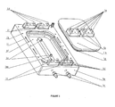
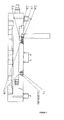
- FIG. 1 illustrates different components which form a cooler device.
- the first component 1 a represents a cooler base plate with different features: 1 i - emptying holes for crossing of electric cables from top surface to bottom surface; 1 h - mounting holes for screws to mount an additional cover to prevent the oxidation of electronic components; 1 d - pins for precise positioning of electronic components on the cooler plate; 1 l - mounting rib for electronic parts on a cooler plate; 1 f - cooling channel; 1 m - rib which separates the inlet and outlet flows of a cooling medium; 1 n - spot-welded supports for the prevention of cover deformation during the operation.
- the second component represents a cooler cover 1 b with a cooling structure in the form of pins 1 g which increases the cooling capacity.
- precise positioning pins 1 e are positioned on the mounting rib 1 k, which have to meet precise positioning tolerances with respect to the positioning pins 1 d on the base plate 1 a.
- the third component presents water connectors 1 c for a connection between the cooling channel 1f and a piping system.
- the design of the die-cast parts 1 a and 1 b is done in a way to optimize the heat transfer from electronic components and to withstand dynamical pressure loads due to pressure peaks over the product life time.
- This means that the design of the part is not optimized primarily for the die casting process of aluminum.
- the die casting process has an advantage of low cost production, but also has a disadvantage of potential porosities 2.1 mp, especially with bigger wall thicknesses.
- the presence of porosity in areas near the mounting holes may cause leakage of cooling media from the cooling channel 1 f through porosity 2.1 mp and mounting holes 1 h for mounting the cooling device. Any leakage of cooling media must be avoided, because it causes short circuit on the electronic components.
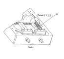
- This type of porosity is called shrinkage micro porosity 2.1 mp and is often present in the middle area of the thick wall as shown on Figure 2.1 .
- Porosity is not present in the area close to the wall surface. Porosity is usually revealed by the machining process, i.e. milling, when preparing the joint interfaces 2.1 a and 2.1 b.
- Joint interfaces, i.e. edges are machined, i.e. milled, to a defined height 2.1 h and width 2.1 x, which corresponds to the thickness of the cover 1b in the joint area, in order to remove surface oxides from the welding surface and to mill away the die casting wall slopes on both parts for the purpose of part assembly. Machining of the cooling device edges is presented on Fig.
- the die casting skin is a surface phenomenon, which consists of different oxides and also represents a leakage protection barrier.
- Fig. 2.2 presents prior art FSW welding.
- FSW tool shoulder 2.2 s and pin 2.2 p form the weld region 2.2 w with welding depth 2.2 h 1 .
- Underneath the weld region a non-welded machine-made joint interface area 2.2 h' is located, through which cooling media can pass from the cooling channel 1 f towards the porosity 2.1 mp and the mounting hole 1 h.
- the design of the die-cast part prevents the enlargement of the welding depth 2.2 h 1 due to the limitation of space 2.2 x' between the welding shoulder 2.2 s and the mounting rib 1 k for electronic parts on cover 1 b.
- the ratio of the diameter 2.2 R of the shoulder 2.2 s to the diameter 2.2 r of the pin 2.2 p at the lower boundary is 2:1. This affects the capability of reaching the maximum welding depth 2.2 h 1 . A prolongation of the welding depth 2.2 h 1 with given welding tool dimensions 2.2 R and 2.2 r due to the given clearance 2.2 x' would result in breakage of the tool due to known ratios.
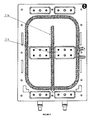
- the joint weld design according to the present invention was developed and is presented on Fig. 3 .
- the machining of the cooler edges is marked 3 a.
- the machining area of the cooler plate joint edge 3.1 a and the cover joint edge 3.1 b is presented in a cross-sectional detailed view on Fig. 3.1 .
- the cooler plate joint edge 3.1 a on the cooler plate 1 a is shaped as a step against which the knee-shaped cover joint edge 3.1 b of the cover 1 b rests. Due to such design of the joint weld, the height 3.1 h of the machined edge is lower than the height 2.1 h of the machined edge in the prior art, while the thickness of the cover remains the same.
- the width 3.1 x of the machined edge, i. e. the removed surface oxides, according to the present invention is smaller than the width 2.1 x in prior art. Since the cooler plate and the cover are pre-casted and no machining is performed on the rest of the joint's interface area, i.e. the edge 3.1 a' on the cooler plate 1 a and the edge 3.1 b' on the cover 1 b, the surface oxide skin on edges 3.1 a' and 3.1 b' stays intact. Due to a lower machining depth, the micro porosity 2.1 mp is not revealed by machining and remains in the middle of the wall.
- Figure 3.2 presents weld region 3.2 w with welding depth 3.2 h 1 . It can be seen that welding depths 2.2 h 1 and 3.2 h 1 are the same, but due to the joint design according to the invention, the machined areas 3.1 a and 3.1 b are inside the welding region 3.2 w and thus completely mixed and sealed by the welding tool. The welding depth 3.2 h 1 is higher than the machining depth 3.1 h.
- Figures 4 and 4.1 present the specially designed ribs 4 a.
- Ribs are also machined, i.e. milled, prior to the welding sequence, and are of a triangular shape and uniformly distributed along the whole joint length. Ribs 4a are provided on the joint edge 3.1 a.
- the first purpose of the machined ribs 4 a on the joint interface is to achieve an equal gap size along the welding trajectory.
- the nature of the FSW process induces high forces in all directions, especially in the direction of welding. These forces have a tendency to push the cooler cover plate 1 b in the direction of welding. This movement in turn induces change in joint gap size along the joined surfaces.
- Unequal joint gap size causes welding faults like void formation and weld underfill which are well-known and unacceptable weld quality faults in application of FSW for coolers.
- the ratio of the width 4.1 x of the rib 4 a to the width 3.1 x of the machined edge enables an easy assembly of the cooler cover 1 b and the cooler plate 1 a, even with a relatively large joint thickness without a need to force the both parts to assemble.
- the second purpose of machined ribs 4 a is to provide exact positioning of the mated joint interfaces. In this way, the exact positioning of the cover positioning pins 1 e with respect to the cooler base plate positioning pins 1 d is achieved after the FSW process is finished. Additional machining of the welded parts at those two positions is avoided.
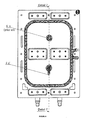
- Figures 6 and 7 present the improved friction stir welding method for manufacturing cooling devices for electronics made using the die casting method. Due to limited space on the cover, linear joint 5 w in the center of the cooler cannot be used, because the space 5 x between the mounting rib 1 k for electronic parts on cover 1 b is too small to use the welding shoulder with diameter 3.2 R as shown in Figure 5 . In order to prevent deformations of the cover during the operational cycle, which may cause a reduction of contact surface between the electronic parts and the cooling surface, two spots welds 6 n' and 6 n instead of one linear weld 5 w are employed. In this way, the overall stiffness of the cooler during pressure peaks is achieved.
- a spot weld support is shaped as an additional circular elevated rib 1 n on the existing rib 1 m which separates the inlet and outlet flows of cooling medium. In this way, the weld is formed despite the thickness of the cover 7 h' being greater than the maximum welding depth 7 h reachable under the given space limitations.
- the welding area for the spot welds is marked with 7 w and 7 w', whereby 7 w represents the prior art welding area and 7 w' represents the welding area according to the invention.
- the welding strategy for the spot welds 6 n and 6 n' is presented in Figure 6 .
- a circular welding path is used.
- the exit hole 7 e of welding tool is in the centre of the circular rib 1 n.
- the spot welding strategy is modified, i.e. the circular welding path is prolonged from the center of the circular rib 1 n for a necessary distance 7 x. In this way, the risk of weld failure and consequential leakage is reduced due to an increased distance between the cooling channel and the weld exit hole.
Landscapes
- Engineering & Computer Science (AREA)
- Mechanical Engineering (AREA)
- Pressure Welding/Diffusion-Bonding (AREA)
- Cooling Or The Like Of Semiconductors Or Solid State Devices (AREA)
Priority Applications (1)
| Application Number | Priority Date | Filing Date | Title |
|---|---|---|---|
| EP14468006.3A EP2965850A1 (fr) | 2014-07-11 | 2014-07-11 | Joint de soudage par friction-malaxage et procédé de fabrication de dispositifs de refroidissement pour composants électroniques |
Applications Claiming Priority (1)
| Application Number | Priority Date | Filing Date | Title |
|---|---|---|---|
| EP14468006.3A EP2965850A1 (fr) | 2014-07-11 | 2014-07-11 | Joint de soudage par friction-malaxage et procédé de fabrication de dispositifs de refroidissement pour composants électroniques |
Publications (1)
| Publication Number | Publication Date |
|---|---|
| EP2965850A1 true EP2965850A1 (fr) | 2016-01-13 |
Family
ID=51263358
Family Applications (1)
| Application Number | Title | Priority Date | Filing Date |
|---|---|---|---|
| EP14468006.3A Withdrawn EP2965850A1 (fr) | 2014-07-11 | 2014-07-11 | Joint de soudage par friction-malaxage et procédé de fabrication de dispositifs de refroidissement pour composants électroniques |
Country Status (1)
| Country | Link |
|---|---|
| EP (1) | EP2965850A1 (fr) |
Cited By (4)
| Publication number | Priority date | Publication date | Assignee | Title |
|---|---|---|---|---|
| GB2536325A (en) * | 2015-03-13 | 2016-09-14 | Lear Corp | Cold plate having separable flow directing baffle |
| JP2020082179A (ja) * | 2018-11-30 | 2020-06-04 | 国立大学法人東海国立大学機構 | 積層造形方法および積層造形装置 |
| JP2021171777A (ja) * | 2020-04-21 | 2021-11-01 | 株式会社アイシン | アルミケース及びアルミケースの製造方法 |
| CN114043070A (zh) * | 2021-12-01 | 2022-02-15 | 宁波江丰电子材料股份有限公司 | 一种靶材背板的搅拌摩擦焊接方法 |
Citations (8)
| Publication number | Priority date | Publication date | Assignee | Title |
|---|---|---|---|---|
| EP0752926B1 (fr) | 1994-03-28 | 1998-05-27 | The Welding Institute | Soudage par friction a mouvement cyclique |
| US6045027A (en) | 1998-03-04 | 2000-04-04 | The Boeing Company | Friction stir welding interlocking joint design and method |
| EP1568434A1 (fr) | 1999-05-28 | 2005-08-31 | Hitachi, Ltd. | Elément de structure et son procédé de fabrication |
| JP2009115448A (ja) * | 2008-12-09 | 2009-05-28 | Nippon Light Metal Co Ltd | ヒートプレートおよびその製造方法 |
| JP2010056196A (ja) * | 2008-08-27 | 2010-03-11 | Nippon Light Metal Co Ltd | 液冷ジャケットおよびその製造方法 |
| US20110308059A1 (en) | 2009-02-23 | 2011-12-22 | Nippon Light Metal Company, Ltd. | Manufacturing method of liquid-cooled jacket |
| JP2013045781A (ja) * | 2011-08-22 | 2013-03-04 | Toyota Motor Corp | 冷却器及びその製造方法 |
| WO2013094246A1 (fr) | 2011-12-19 | 2013-06-27 | 日本軽金属株式会社 | Procédé de fabrication d'une chemise de refroidissement à circulation liquide |
-
2014
- 2014-07-11 EP EP14468006.3A patent/EP2965850A1/fr not_active Withdrawn
Patent Citations (8)
| Publication number | Priority date | Publication date | Assignee | Title |
|---|---|---|---|---|
| EP0752926B1 (fr) | 1994-03-28 | 1998-05-27 | The Welding Institute | Soudage par friction a mouvement cyclique |
| US6045027A (en) | 1998-03-04 | 2000-04-04 | The Boeing Company | Friction stir welding interlocking joint design and method |
| EP1568434A1 (fr) | 1999-05-28 | 2005-08-31 | Hitachi, Ltd. | Elément de structure et son procédé de fabrication |
| JP2010056196A (ja) * | 2008-08-27 | 2010-03-11 | Nippon Light Metal Co Ltd | 液冷ジャケットおよびその製造方法 |
| JP2009115448A (ja) * | 2008-12-09 | 2009-05-28 | Nippon Light Metal Co Ltd | ヒートプレートおよびその製造方法 |
| US20110308059A1 (en) | 2009-02-23 | 2011-12-22 | Nippon Light Metal Company, Ltd. | Manufacturing method of liquid-cooled jacket |
| JP2013045781A (ja) * | 2011-08-22 | 2013-03-04 | Toyota Motor Corp | 冷却器及びその製造方法 |
| WO2013094246A1 (fr) | 2011-12-19 | 2013-06-27 | 日本軽金属株式会社 | Procédé de fabrication d'une chemise de refroidissement à circulation liquide |
Cited By (6)
| Publication number | Priority date | Publication date | Assignee | Title |
|---|---|---|---|---|
| GB2536325A (en) * | 2015-03-13 | 2016-09-14 | Lear Corp | Cold plate having separable flow directing baffle |
| US9622377B2 (en) | 2015-03-13 | 2017-04-11 | Lear Corporation | Cold plate having separable flow directing baffle |
| GB2536325B (en) * | 2015-03-13 | 2019-06-05 | Lear Corp | Cold plate having separable flow directing baffle |
| JP2020082179A (ja) * | 2018-11-30 | 2020-06-04 | 国立大学法人東海国立大学機構 | 積層造形方法および積層造形装置 |
| JP2021171777A (ja) * | 2020-04-21 | 2021-11-01 | 株式会社アイシン | アルミケース及びアルミケースの製造方法 |
| CN114043070A (zh) * | 2021-12-01 | 2022-02-15 | 宁波江丰电子材料股份有限公司 | 一种靶材背板的搅拌摩擦焊接方法 |
Similar Documents
| Publication | Publication Date | Title |
|---|---|---|
| US11707798B2 (en) | Method for manufacturing liquid-cooled jacket | |
| US10518369B2 (en) | Method for manufacturing heat exchanger plate and method for friction stir welding | |
| US11654508B2 (en) | Method for producing liquid-cooled jacket | |
| US11712748B2 (en) | Method for producing liquid-cooled jacket | |
| CN107000114B (zh) | 液冷套筒的制造方法及液冷套筒 | |
| EP2965850A1 (fr) | Joint de soudage par friction-malaxage et procédé de fabrication de dispositifs de refroidissement pour composants électroniques | |
| JP6372515B2 (ja) | 液冷ジャケットの製造方法及び液冷ジャケット | |
| JP6769427B2 (ja) | 液冷ジャケットの製造方法 | |
| WO2019150610A1 (fr) | Procédé de fabrication d'une chemise de refroidissement par liquide | |
| JP2007222925A (ja) | 摩擦攪拌接合方法 | |
| WO2019123679A1 (fr) | Procédé de fabrication d'une chemise de refroidissement par liquide | |
| KR101665275B1 (ko) | 히트 싱크의 제조 방법 및 전열판의 제조 방법 | |
| US11806801B2 (en) | Joining method | |
| KR20150039080A (ko) | 마찰 교반용접 플러그와 그 사용방법 | |
| JP2009115448A (ja) | ヒートプレートおよびその製造方法 | |
| JP6834850B2 (ja) | 液冷ジャケットの製造方法 | |
| JP2010253534A (ja) | 冷却路内蔵部材および冷却路内蔵部材の製造方法 | |
| CN111093880A (zh) | 液冷套的制造方法 | |
| JP6577696B2 (ja) | 内部に流路を設けない複合板の製造方法 | |
| US9676057B2 (en) | Device for solid state joining of light metals | |
| US20150151479A1 (en) | Method for sealing cooling channels of a drink packaging machine | |
| US11904571B2 (en) | Composite material structure and processing method thereof | |
| WO2021231857A2 (fr) | Systèmes et procédés de soudage par friction-malaxage d'une plaque froide | |
| JP2020028896A (ja) | 回転ツール、接合方法及び液冷ジャケットの製造方法 | |
| JP2021094566A (ja) | 金属構造体の製造方法、及び金属構造体 |
Legal Events
| Date | Code | Title | Description |
|---|---|---|---|
| PUAI | Public reference made under article 153(3) epc to a published international application that has entered the european phase |
Free format text: ORIGINAL CODE: 0009012 |
|
| AK | Designated contracting states |
Kind code of ref document: A1 Designated state(s): AL AT BE BG CH CY CZ DE DK EE ES FI FR GB GR HR HU IE IS IT LI LT LU LV MC MK MT NL NO PL PT RO RS SE SI SK SM TR |
|
| AX | Request for extension of the european patent |
Extension state: BA ME |
|
| STAA | Information on the status of an ep patent application or granted ep patent |
Free format text: STATUS: THE APPLICATION IS DEEMED TO BE WITHDRAWN |
|
| 18D | Application deemed to be withdrawn |
Effective date: 20160714 |