EP2965737B1 - Gaskommunikationsvorrichtung, Gasversorgungsanordnung und Gasversorgungseinstellverfahren - Google Patents
Gaskommunikationsvorrichtung, Gasversorgungsanordnung und Gasversorgungseinstellverfahren Download PDFInfo
- Publication number
- EP2965737B1 EP2965737B1 EP14176426.6A EP14176426A EP2965737B1 EP 2965737 B1 EP2965737 B1 EP 2965737B1 EP 14176426 A EP14176426 A EP 14176426A EP 2965737 B1 EP2965737 B1 EP 2965737B1
- Authority
- EP
- European Patent Office
- Prior art keywords
- gas
- engagement
- communication device
- supplier
- gas supply
- Prior art date
- Legal status (The legal status is an assumption and is not a legal conclusion. Google has not performed a legal analysis and makes no representation as to the accuracy of the status listed.)
- Not-in-force
Links
- 238000004891 communication Methods 0.000 title claims description 92
- 238000000034 method Methods 0.000 title claims description 14
- 238000000926 separation method Methods 0.000 claims description 19
- 230000001737 promoting effect Effects 0.000 claims description 3
- 230000008859 change Effects 0.000 description 7
- 230000013011 mating Effects 0.000 description 2
- 230000008569 process Effects 0.000 description 2
- 208000004210 Pressure Ulcer Diseases 0.000 description 1
- 238000002680 cardiopulmonary resuscitation Methods 0.000 description 1
- 230000006835 compression Effects 0.000 description 1
- 238000007906 compression Methods 0.000 description 1
- 230000008878 coupling Effects 0.000 description 1
- 238000010168 coupling process Methods 0.000 description 1
- 238000005859 coupling reaction Methods 0.000 description 1
- 230000005489 elastic deformation Effects 0.000 description 1
- 239000013013 elastic material Substances 0.000 description 1
- 230000010354 integration Effects 0.000 description 1
- 239000011159 matrix material Substances 0.000 description 1
- 238000000465 moulding Methods 0.000 description 1
- 230000000717 retained effect Effects 0.000 description 1
Images


Classifications
-
- A—HUMAN NECESSITIES
- A61—MEDICAL OR VETERINARY SCIENCE; HYGIENE
- A61G—TRANSPORT, PERSONAL CONVEYANCES, OR ACCOMMODATION SPECIALLY ADAPTED FOR PATIENTS OR DISABLED PERSONS; OPERATING TABLES OR CHAIRS; CHAIRS FOR DENTISTRY; FUNERAL DEVICES
- A61G7/00—Beds specially adapted for nursing; Devices for lifting patients or disabled persons
- A61G7/05—Parts, details or accessories of beds
-
- A—HUMAN NECESSITIES
- A61—MEDICAL OR VETERINARY SCIENCE; HYGIENE
- A61G—TRANSPORT, PERSONAL CONVEYANCES, OR ACCOMMODATION SPECIALLY ADAPTED FOR PATIENTS OR DISABLED PERSONS; OPERATING TABLES OR CHAIRS; CHAIRS FOR DENTISTRY; FUNERAL DEVICES
- A61G12/00—Accommodation for nursing, e.g. in hospitals, not covered by groups A61G1/00 - A61G11/00, e.g. trolleys for transport of medicaments or food; Prescription lists
- A61G12/002—Supply appliances, e.g. columns for gas, fluid, electricity supply
-
- A—HUMAN NECESSITIES
- A61—MEDICAL OR VETERINARY SCIENCE; HYGIENE
- A61G—TRANSPORT, PERSONAL CONVEYANCES, OR ACCOMMODATION SPECIALLY ADAPTED FOR PATIENTS OR DISABLED PERSONS; OPERATING TABLES OR CHAIRS; CHAIRS FOR DENTISTRY; FUNERAL DEVICES
- A61G7/00—Beds specially adapted for nursing; Devices for lifting patients or disabled persons
- A61G7/05—Parts, details or accessories of beds
- A61G7/057—Arrangements for preventing bed-sores or for supporting patients with burns, e.g. mattresses specially adapted therefor
- A61G7/05769—Arrangements for preventing bed-sores or for supporting patients with burns, e.g. mattresses specially adapted therefor with inflatable chambers
Definitions
- the present invention is defined by the appended claims and relates to a gas communication device, a gas supply assembly and a gas supply adjustment method and more particularly to a device, assembly and method applicable to gas supply and exhaust of an air mattress, wherein the gas communication device may be easily connected to and separated from a gas supplier, and the problems associated to the placement of the gas communication device can be prevented.
- An air mattress or airbed is a mattress or sleeping pad consisting of one or more inflatable cells or tubes and may generally be categorized into a general purpose air mattress and a medical air mattress.
- the medical air mattress is particularly suitable for a bedridden patient as it relieves local stress concentration and prevents bedsores.
- an air mattress set generally comprises a mattress main body, a gas supplier and a gas communication device.
- the mattress main body has one or more air tubes.
- the gas supplier comprises an air pump with adjustable air supply and discharge settings.
- the gas communication device is arranged between the mattress main body and the gas supplier to form air communication between the mattress main body and the gas supplier, such that the gas supplier can inflate or deflate the mattress main body to adjust the hardness/softness of the mattress main body.
- the gas communication device may be provided with a quick disassembly and assembly structure.
- TW Patent No. M427485 discloses a gas delivery connector set comprising a connector holder connected with a gas supplier and a gas delivery connector for rapid connection to and separation from the connector holder, wherein the gas delivery connector has one end connected to the mattress main body via a tube and the other end connected with the connector holder via two hook structures. When the gas delivery connector is inserted into the connector holder, gas communication is formed between the mattress main body and the gas supplier.
- the gas delivery connector is fastened with the connector holder by two hook structures, when a user tries to remove the gas delivery connector to allow rapid deflation of the air mattress, in particular when a patient is in urgent need of cardiopulmonary resuscitation (CPR), the user has to press both hook structures with two fingers to achieve disengagement, which undesirably makes the operation very inconvenient, and the gas delivery connector cannot be removed without delicate manipulation.
- the two hook structures are pressed by two fingers respectively, the gas delivery connector cannot be automatically ejected or separated from the connector holder, and the user has to pull the gas delivery connector backward to completely remove it from the connector holder.
- US 5562121 A discloses a gas outlet system that includes a first indexing structure mating with a first adaptor for releasably connecting the first adaptor to the outlet, and a second indexing structure mating with a second adaptor for releasably connecting the second adaptor to the outlet.
- the gas outlet system includes an engaging member for engaging the adaptor to the outlet and includes first and second urging members each independently operable to disengage the engaging member to release the adaptor.
- An objective of this invention is to provide a gas communication device, a gas supply assembly, and a gas supply adjustment method applicable to the gas supply and gas exhaust between a gas supplier and an air mattress.
- the gas communication device may be conveniently and easily connected to or separated from the gas supplier, thereby increasing the gas supply and discharge adjustment efficiency of the air mattress.
- this invention provides a gas communication device connectable between a gas supplier and, for example, an air mattress, to inflate and deflate the air mattress.
- a gas communication device comprises: a main body connected to the gas supplier, the main body comprising a base and a cover, wherein the base has a gas inlet corresponding to the gas supplier and a gas outlet connected with the air mattress, and the cover being arranged on the base; an engagement member movably disposed in the main body for engaging a corresponding structure on the gas supplier; a press member, which can be manipulated with one finger, operably linked to the engagement member to enable a user to press and manipulate the press member to induce the disengagement of the engagement member from the gas supplier; and at least one release member, such as an elastic structure, with at least a part disposed in the main body.
- the release member when the gas communication device is combined with or connected to the gas supplier through the engagement member, the release member is structurally changed such as due to compression and deformed to store mechanical energy (resilience).
- the engagement member When the user presses the press member, the engagement member is driven to disengage from the gas supplier, and at the same time the structural change of the release member, such as the release of mechanical energy (resilience), enables the separation of the main body from the gas supplier to promote gas discharge from the air mattress, thereby achieving the purpose of convenient engagement or connection and disengagement or disconnection and increasing the convenience in use.
- this invention provides a gas communication device connected between a gas supplier and an article to be inflated or deflated, such as an air mattress.
- the gas communication device mainly comprises a main body comprising a base and a cover disposed on the base; an engagement member movably disposed in the main body; a press member operably linked to the engagement member; and at least one release member at least partially disposed in the main body.
- this invention provides a gas supply assembly applicable to an air mattress, mainly comprising: a gas supplier having at least one engagement structure; and a gas communication device which comprises a housing, an engagement member and a release member, the housing having at least one gas inlet in gas communication with the gas supplier, the engagement member being arranged corresponding to the engagement structure such that the housing may be connected to or removed from the gas supplier, the release member being arranged as elastically deformable toward the gas supplier.
- the engagement member and the engagement structure may be used to engage or combine the gas communication device and the gas supplier; when the engagement member is disengaged from the engagement structure, the compressed and deformed release member may release resilience to promote the separation of the gas inlet of the main body from the gas supply opening of the gas supplier, thereby allowing rapid deflation of the air mattress.
- the structural configuration of the engagement structure of the gas supplier enables the gas communication device to be hanged on the gas supplier without complete removal therefrom, so as to overcome the problems associated to the placement of the gas communication device.
- this invention provides a method of adjusting gas supply to an air mattress in gas communication with a gas supply assembly which comprises a gas supplier and a gas communication device.
- the method mainly comprises disengaging the gas communication device from the gas supplier, thereby enabling elastic deformation of a release member to promote the disengagement or removal of the gas communication device from the gas supplier.
- the terms “comprises,” “comprising,” “includes,” “including,” “has,” “having” or any other variation thereof are intended to cover a non-exclusive inclusion.
- a component, structure, article, or apparatus that comprises a list of elements is not necessarily limited to only those elements but may include other elements not expressly listed or inherent to such component, structure, article, or apparatus.
- the terms “first,” “second,” “third” and the like are used for distinguishing between or referring identical or similar elements or structures and not necessarily for describing a sequential or chronological order thereof. It should be understood that the terms so used are interchangeable under appropriate circumstances or configurations and that the embodiments of the invention described herein are operable in other sequences than described or illustrated herein. Moreover, the terms “upper,” “lower,” “left,” “right” and the like in the description and the claims are used for describing relative positions of articles or structures and not necessarily limiting the absolute positions thereof; on the contrary, the terms so used are interchangeable under appropriate circumstances or configurations.
- the position of an upper opening is higher than that of a lower opening, but when the surrounding or orientation has been changed, the upper opening may become the lower opening, and the lower opening may become the upper opening.
- the upper opening may also become the left opening or the right opening, vice versa.
- up-down movement can also be implemented as left-right movement or inclined movement.
- main body shall describe a main portion of a physical structure, which may optionally comprise a base and a cover removably connected with the base or integrally formed with the base such that the base and the cover are configured as two portions of the main body.
- the "main body” acts as a reference for the movements of respective movable elements and as a matrix for the connection of various elements or structures.
- engagement or the like is interpreted in the broadest sense comprehensible by a person skilled in the art, including but not limited to direct connection or linkage where two elements or structures are in contact with each other and no intermediate exists therebetween, indirect connection or linkage where an intermediate exists between two elements or structures to be connected, and movable connection where the motion of one element or structure is constrained by the other.
- Engagement comprises direct or indirect fitting, fixing, coupling and similar connection configurations and preferably comprises temporary engagement where two mutually engaged structures may be operably linked in a separable or disengageable way.
- movable engagement or the like describes the engagement of two structures or objects where one is rotatable or movable relative to the other.
- engagement member describes a component, element or part having an engagement structure and being engageable with another component, element or part.
- the term “movable” or the like refers to an article or a part thereof which may be subject to spatial or orientation change or variation, including movement and rotation.
- the term “operably linked” or the like describes that the structural or spatial variation of an article or a part thereof causes, directly or indirectly, the structural or spatial variation of another article or a part thereof, whether or not the objects are in contact with each other.
- the term “release,” “separation,” “removal” and the like are used interchangeably to describe the change of two objects or parts thereof from a closer state to a more distant state, including complete separation where separated objects or parts thereof are no longer in contact with each other or partial separation where separated objects or parts thereof are still in contact.
- release “separation,” or “removal” describes that the major portions or surfaces of two objects are not connected or adhered to each other.
- housing refers to an object for receiving an element or portions thereof.
- a housing is typically the outmost portion of a device, but not limited thereto.
- elastic connection refers to direct or indirect connection of two structures where a force may be imposed to any one of them to change the relative spatial relationship of the structures, and after the force disappears, the original relative spatial relationship is resumed.
- deformation describes structural or configuration variation or change of an object, for example a release member, such as length variation at different states or conditions.
- connection means “combined, joined, linked or assembled together,” and includes direct connection where no intermediate (e.g. a gasket or washer) exists and indirect connection where an intermediate exists between two elements to be connected.
- these components may form an integral, one-piece structure such as by integration in which different components act as different parts or portions of the integral structure, or these components may be distinct and separate components connected together.
- means for joining distinct and separate components together includes interlocking, engagement, fastening, mortise and tenon joint, or any other connection means known and understood in the mechanical arts.
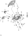
- the gas communication device 10 of one embodiment of this invention is a connector which can be rapidly connected to and removed from a gas supplier 20.
- the gas communication device 10 and the gas supplier 20 are used together, they as a whole form a gas supply assembly 100 for inflating an air mattress.
- the gas communication device 10 comprises a main body 1, an engagement member 3, a manipulative member 5 (such as a press member) and at least one release member 7.
- the main body 1 may be connected to the air mattress via gas delivery tubes and be rapidly connected to the gas supplier 20.
- the main body 1 may be formed by the assembly or integrated molding of multiple sub-components.
- the main body 1 may be a housing 11, which is preferably composed of a base 12 and a cover 13 connected with the base 12, configured for completely or partially receive the aforesaid engagement member 3, manipulative member 5 and release member 7.
- the base 12 has a connection plane 120 facing towards the gas supplier 20, and one or more gas inlets 121 may be formed on the connection plane 120.
- the channel defined by the gas inlet 121 may be extended to other surfaces of the base 12 to form one or more gas delivery pipe parts 122 with one end communicated with the gas inlet 121 and the other end forming a gas outlet 123 connected with a gas delivery tube.
- one side of the base 12 opposite to the connection plane 120 defines a receiving space 124 through which the gas delivery pipe part 122 is extended to the bottom of the base 12.
- the receiving space 124 may be provided with a longitudinal guide block 125 and an oblique guide block 126 therein.
- the longitudinal guide block 125 defines a longitudinal slide slot 127 in which the engagement member 3 is slidably arranged.
- the oblique guide block 126 defines an oblique slide slot 128 with one end communicated with the longitudinal slide slot 127, such that the press member or manipulative member 5 or a part thereof may be slidably disposed in the oblique slide slot 128.
- the manipulative member 5 slides along the oblique slide slot 128 and then abuts against the engagement member 3 so as to drive the engagement member 3 to slide longitudinally along the longitudinal slide slot 127.
- the cover 13 may be assembled with and covered on the base 12.
- the cover 13 may be configured as a curved shape or any shape that can be held by the user with one hand easily and be combined with the base 12 to cover the receiving space 124.
- one or more hooks 131 on the cover 13 may be engaged or interlocked with the corresponding structures on the base 12, and one or more fastening elements 14, such as screws, may be used to fasten the base 12 and the cover 13.
- the cover 13 is defined thereon with a circular or elliptic push button hole 132, such that after the base 12 is combined with the cover 13, a portion of the manipulative member 5, e.g. the press member, is exposed from the cover 13 through the push button hole 132, thereby allowing the user to actuate or press the manipulative member 5 with one finger to actuate the engagement member 3.
- the engagement member 3 is received in the housing 11 such as in an elastically movable manner for engaging the gas supplier 20.
- the engagement member 3 may be configured as a rigid sheet with a U-shape or any other shape movably disposed in the longitudinal slide slot 127, and the engagement member 3 is provided with an engagement part 31 for engaging the gas supplier 20, such as an engagement slit 311 formed on the engagement member 3.
- the engagement part 31 may also be configured as other structures capable of forming engagement.
- the tips at two sides of the engagement member 3 may be respectively connected with an elastic member 32, such as a spiral spring or other springs, arranged at the bottom of the longitudinal slide slot 127 of the base 12, such that the engagement member 3 may be arranged in the longitudinal slide slot 127 in an elastically movable manner to slide between an engagement orientation and a disengagement orientation.
- an elastic member 32 such as a spiral spring or other springs
- the manipulative member 5 such as a structure to be pressed by the user, may be manipulated by the user with one finger so as to drive the sliding operation of the engagement member 3, as indicated by the arrow in FIG. 5 .
- the press member or manipulative member 5 is a circular push button 51 connected from the bottom with two arms 52, such as two rod-like structures extended downwardly from two sides of the push button 51.
- the two arms 52 are movably arranged in the oblique slide slot 128 of the base 12 with their tips obliquely rested on or abutted against the engagement member 3, and the push button 51 is protruded from the push button hole 132 of the cover 13.
- the manipulative member 5 slides along the oblique slide slot 128 toward the base 12, and downward component of force from the arms 52 drives longitudinal or downward movement of the engagement member 3, thus disengaging the engagement part 31 from the gas supplier 20.
- the user may align the engagement part 31 of the engagement member 3 of the gas communication device 10 to the corresponding engagement structure 22 on the gas supplier 20 (an embodiment allowing convenient alignment is described below), and push the gas communication device 10 toward the gas supplier 20, during which the engagement part 31 elastically slides downward via the elastic member 32 along the longitudinal slide slot 127 and forms engagement with the engagement structure 22 after it is elastically repositioned, allowing easy and convenient assembly of the gas communication device 10 and the gas supplier 20.
- the release member 7 is a component for promoting the separation of the gas communication device 10 from the gas supplier 20. It is structurally changeable, such as generating elastic force, during the disengagement between the engagement member 3 and the engagement structure 22, so as to facilitate the removal of the gas communication device 10 from the gas supplier 20 and reduce user's effort required to withdraw the gas communication device 10, thereby making the removal and separation easier.
- the release member 7 is at least partially disposed in the main body 1. As illustrated in FIG. 2 , in a preferred embodiment, the base 12 of the main body 1 is provided with one or more receiving holes 15 on the connection plane 120 for correspondingly receiving one or more release members 7. In one embodiment, two release members 7 are respectively arranged in left and right receiving holes 15 formed symmetrically relative to the longitudinal axis of the main body 1. When the release members 7 have not been deformed or structurally changed, a part thereof is received in the corresponding receiving hole 15 and the other part is exposed therefrom.
- the release member 7 will be squeezed in between the main body 1 and the gas supplier 20 and thereby compressed to store mechanical energy for promoting the separation of the gas supplier 20 and the gas communication device 10.
- the release member 7 may be an elastic structure or elastic pin made of spring or elastic material.
- the release member 7 has a cylindrical structure with a first portion 71 and a second portion 72.
- the first portion 71 has a diameter greater than that of the second portion 72, such that first portion 71 may be retained within the receiving hole 15, and the second portion 72 is elastically deformable when pressed. Therefore, when the engagement member 3 is disengaged from the gas supplier 20, the mechanical energy (resilience) produced by the deforming release member 7 may promote the separation of the gas communication device 10 from the gas supplier 20, as illustrated in FIG. 6 .
- the structural design and configuration of the main body 1, the engagement member 3, the press member 5 and the release member 7 allows rapid connection of the main body 1, such as the housing 11, via the engagement member 3 onto a side wall of the gas supplier 20, such that the gas inlet 121 is communicated with the gas supply opening of the gas supplier 20 to form a gas supply assembly 100 suitable for an air mattress and useful for inflating the air mattress or adjusting the hardness/softness of the air mattress.
- the user only needs to press the manipulative member 5 with one finger to move the engagement member 3 disengage the engagement member 3 from the gas supplier 20.
- the deformation or structural change of the release member 7 facilitates the movement or rotation of the gas communication device 10 away from the gas supplier 20 so as to save the effort required to remove or unplug the gas communication device 10 and achieve the purpose of convenient separation to stop gas supply to the air mattress or allow gas discharge from the air mattress.
- this invention provides a gas supply assembly 100 composed of the aforesaid gas communication device 10 and gas supplier 20.
- FIGs. 2 and 3 respectively illustrate the preferred combination and separation configurations of the two components.
- connection plane 120 of the housing 11 is provided with a first opening 16, such as an upper opening, corresponding to the engagement part 31, such as an engagement slit 311, of the engagement member 3.
- the engagement member 3 is arranged in a manner movable relative to the first opening 16, such as vertically movable or slidable parallel to the connection plane 120.
- the inclined plane design enables the engagement member 3 to be pushed downward and then repositioned and thereby engaged with the first engagement portion 221.
- the engagement member 3 may be driven to disengage from the first engagement portion 221.
- the first engagement portion 221 is not obstructed by the engagement member 3 and may be removed therefrom through the first opening 16, and the release member 7 provides assistance to more easily remove the engagement member 3 from the first engagement portion 221 so as to separate the gas communication device 10 from the gas supplier 20.
- the housing 11 can further be provided with at least one second opening 17, such as a lower opening.
- at least one second opening 17 can be formed at the bottom of the housing 11 symmetrically relative to the longitudinal axis of the main body 1 to facilitate the alignment of the gas communication device 10 to the gas supplier 20 and temporarily mount or hang the gas communication device 10 on the gas supplier 20.
- the configuration of the second openings 17 and the second engagement portion 222 enables movable engagement between the housing 11 and the gas supplier 20, thereby preventing the gas communication device 10 from being completely separated or fallen from the gas supplier 20.
- first opening 16 and the second opening 17 may be respectively configured as a left opening and a right opening.
- first opening 16 and the second opening 17 may be configured as oblique arrangement or front-and-rear arrangement relative to the longitudinal axis of the gas supplier 20. That is, unless otherwise specified, the positions of various structures and elements of this invention are adjustable according to the need and circumstance in actual use and not limited to those disclosed in this specification and drawings.
- the gas supplier 20 and the gas communication device 10 are combined to form the gas supply assembly 100 for the air mattress.
- One side of the gas supplier 20 is provided with one or more gas supply openings 21, any of which may be sealed by a rubber seal if needed.
- the gas supply opening 21 is matched and communicated with the gas inlet 121 of the gas communication device 10, such that gas outputted from the gas supply opening 21 is passed through the gas inlet 121, the gas delivery pipe part 122 and the gas delivery tube to the air mattress for inflation.
- the gas supplier 20 is preferably provided at one side with one or more engagement structures 22, such as two pairs of engagement structures 22 arranged at the upper and lower portions illustrated in FIG. 3 .
- the engagement member 3 may be correspondingly engaged with any one of the engagement structures 22. Therefore, the structural correspondence between the engagement structures 22 and the engagement member 3 allows the user to mount the gas communication device 10 to any desirable position on the gas supplier 20 to carry out different gas adjustment functions.
- the release member 7 is structurally deformable, such as from a compressed state to a stretched state, when at least a part of the engagement structures 22 is disengaged from the engagement member 3, so as to promote the separation of the gas communication device 10 from the gas supplier 20, as illustrated in FIG. 6 .
- each engagement structure 22 may have a first engagement portion 221 and a second engagement portion 222, as illustrated in FIG. 3 .
- the first engagement portion 221 is preferably configured as a first hook protrudingly arranged on the surface of the gas supplier 20 and facing downward, such that it may secure the engagement member 3 from the lower edge of the engagement part 31, such as the engagement slit 311, through the first opening 16 of the housing 11, making the gas communication device 10 secured at one side of the gas supplier 20, as illustrated by FIG. 4 .
- the press member 5 slides obliquely into the main body 1, as illustrated in FIG. 5 , such that the downward component of force from the arms 52 pushes the engagement member 3 to disengage the engagement part 31 and the first engagement portion 221.
- the first engagement portion 221 can be engaged with the engagement member 3 through the first opening 16 by the operation described above.
- the second engagement portion 222 is preferably configured as a second hook protruded upward.
- the user wants to connect the gas communication device 10 to the gas supplier 20, he or she may first mount the housing 11 on the second engagement portion 222 through the second opening 17, such that the second hook of the second engagement portion 222 hooks and secures the second opening 17.
- the first engagement portion 221 and the engagement member 3 can be correspondingly engaged to easily and firmly connect the gas communication device 10 to one side of the gas supplier 20, greatly simplifying the alignment process.
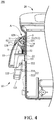
- the gas communication device 10 can be arranged relative to the gas supplier 20 at a first orientation A (engaged state) and a second orientation B (partially separated state).
- the first opening 16 e.g. the upper opening
- the second opening 17 e.g. the lower opening
- the engagement member 3 is separated from the first engagement portion 221, and the second opening 17 is secured by the second engagement portion 222, such that the gas communication device 10 can be obliquely rested on the gas supplier 20 at a partial separation configuration illustrated in FIG. 6 . Accordingly, this embodiment allows partial separation of the gas communication device 10 from the gas supplier 20 and terminates the gas communication therebetween.
- the inclined plane of the second engagement portion 222 in conjunction with the second opening 17 allows the gas communication device 10 to be obliquely mounted to one side of the gas supplier 20 and convenient placement of the gas communication device 10, avoiding damage due to improper placement, and allows rapid combination of the gas communication device 10 and the gas supplier 20 whenever needed.
- this invention further provides a method of adjusting gas supply to an air mattress, which is particularly useful for adjusting gas supply or gas exhaust of the air mattress in gas communication with the above-recited gas supply assembly 100, for example.
- the method comprises first disengaging the gas communication device 10 from the gas supplier 20, thereby allowing deformation or structural change of the release member 7 to promote the separation of the gas communication device 10 from the gas supplier 20, with the assistance of the release member 7 pushing against the gas supplier 20. Therefore, by employing the method of adjusting gas supply to the air mattress, the user can more easily remove the gas communication device 10 from the gas supplier 20 completely, or separate the gas communication device 10 partially from and hang it on the gas supplier 20, so as to simplify the adjustment of gas supply and gas exhaust of the air mattress.
- the method of adjusting gas supply to the air mattress is also useful for the adjustment of gas supply or gas exhaust between the air mattress and the gas supply assembly not yet in gas communication, which mainly comprises first mounting or movably engaging the gas communication device, which is connected to the air mattress via a gas delivery tube, by one end, such as by the lower portion, to the gas supplier, and then pushing the gas communication device toward the gas supplier to engage the opposite end, such as the upper portion, with the gas supplier, so as to firmly combine the gas supplier and the gas communication device from two ends and form gas communication therebetween.
Landscapes
- Health & Medical Sciences (AREA)
- Nursing (AREA)
- Life Sciences & Earth Sciences (AREA)
- Animal Behavior & Ethology (AREA)
- General Health & Medical Sciences (AREA)
- Public Health (AREA)
- Veterinary Medicine (AREA)
- Mattresses And Other Support Structures For Chairs And Beds (AREA)
Claims (11)
- Eine Gasversorgungsanordnung (100) für eine Luftmatratze, bestehend aus:einem Gasversorger (20) mit einer Kupplungsstruktur (22); undeiner Gaskommunikationsvorrichtung (10) mit einem Gehäuse (11), einem Kupplungsglied (3) und einem Freigabeglied (7), wobei das Gehäuse (11) mindestens eine Gaseinlassöffnung (121) in der Gaskommunikation mit dem Gasversorger (20) aufweist, und das Kupplungsglied (3) so angeordnet ist, dass es der Kupplungsstruktur (22) entspricht, sodass das Gehäuse (11) an den Gasversorger (20) angeschlossen bzw. davon abgetrennt werden kann, dadurch gekennzeichnet, dass das Freigabeglied (7) so angeordnet ist, dass es in Richtung des Gasversorgers (20) verformbar ist, sodass sich das Freigabeglied (7) elastisch verformt, wenn die Kupplungsstruktur (22) und das Kupplungsglied (3) ausgekuppelt werden, wodurch die Trennung der Gaskommunikationsvorrichtung (10) vom Gasversorger (20) gefördert wird.
- Die Gasversorgungsanordnung (100) nach Anspruch 1, wobei das Gehäuse (11) ein Aufnahmeloch (15) zur Aufnahme des Freigabeglieds (7) aufweist.
- Die Gasversorgungsanordnung (100) nach Anspruch 1, wobei die Gaskommunikationsvorrichtung (10) relativ zum Gasversorger (20) zwischen einer ersten Ausrichtung (A) und einer zweiten Ausrichtung (B) schaltbar ist, und wobei die Gaskommunikationsvorrichtung (10) luftdicht an den Gasversorger (20) an der ersten Ausrichtung (A) angeschlossen ist und das Kupplungsglied (3) von der Kupplungsstruktur (22) an der zweiten Ausrichtung (B) ausgekuppelt ist.
- Eine Gasversorgungsanordnung (100) nach Anspruch 3, wobei die Kupplungsstruktur (22) einen oberen Kupplungsteil (221) und einen unteren Kupplungsteil (222) umfasst, das Gehäuse (11) eine obere Öffnung (16) und eine untere Öffnung (17) umfasst, die dem oberen Kupplungsteil (221) bzw. dem unteren Kupplungsteil (222) entsprechen, und wobei das Kupplungsglied (3) beweglich angeordnet ist, um die Einkupplung oder Auskupplung des oberen Kupplungsteils (221) und des unteren Kupplungsteils (3) durch die obere Öffnung (16) zu ermöglichen.
- Die Gasversorgungsanordnung (100) nach Anspruch 4, wobei an der ersten Ausrichtung (A) der obere Kupplungsteil (221) mit dem Kupplungsglied (3) durch die obere Öffnung (16) und der untere Kupplungsteil (222) mit dem Gehäuse (11) durch die untere Öffnung (17) eingekuppelt ist, und wobei an der zweiten Ausrichtung (B) der obere Kupplungsteil (221) vom Kupplungsteil (3) ausgekuppelt ist und der untere Kupplungsteil (222) beweglich mit dem Gehäuse (11) eingekuppelt ist (B).
- Die Gasversorgungsanordnung (100) nach Anspruch 1, wobei der Kupplungsteil (3) elastisch mit dem Gehäuse (11) verbunden ist.
- Die Gasversorgungsanordnung (100) nach Anspruch 1, die ferner ein manipulierbares Teil (5) zur Aktivierung des Kupplungsglieds (3) enthält.
- Die Gaskommunikationsvorrichtung (10) nach Anspruch 7, wobei das manipulierbare Teil (5) ein Druckknopf (51) ist.
- Die Gaskommunikationsvorrichtung (10) nach Anspruch 1, wobei das Freigabeglied (7) ein elastischer Stift ist.
- Die Gaskommunikationsvorrichtung (10) nach Anspruch 1, wobei das Freigabeglied (7) mindestens teilweise im Gehäuse (11) angeordnet ist.
- Ein Verfahren zum Einstellen der Gasversorgung für eine Luftmatratze in der Gaskommunikation mit einer Gasversorgungsanordnung (100), die einen Gasversorger (20) und eine Gaskommunikationsvorrichtung (10) enthält, wobei das Verfahren in der Auskupplung der Gaskommunikationsvorrichtung (10) vom Gasversorger (20) besteht, sodass sich das Freigabeglied (7) verformen kann, um die Auskopplung der Gaskommunikationsvorrichtung (10) vom Gasversorger (20) zu fördern.
Priority Applications (1)
| Application Number | Priority Date | Filing Date | Title |
|---|---|---|---|
| EP14176426.6A EP2965737B1 (de) | 2014-07-10 | 2014-07-10 | Gaskommunikationsvorrichtung, Gasversorgungsanordnung und Gasversorgungseinstellverfahren |
Applications Claiming Priority (1)
| Application Number | Priority Date | Filing Date | Title |
|---|---|---|---|
| EP14176426.6A EP2965737B1 (de) | 2014-07-10 | 2014-07-10 | Gaskommunikationsvorrichtung, Gasversorgungsanordnung und Gasversorgungseinstellverfahren |
Publications (2)
| Publication Number | Publication Date |
|---|---|
| EP2965737A1 EP2965737A1 (de) | 2016-01-13 |
| EP2965737B1 true EP2965737B1 (de) | 2017-11-01 |
Family
ID=51162560
Family Applications (1)
| Application Number | Title | Priority Date | Filing Date |
|---|---|---|---|
| EP14176426.6A Not-in-force EP2965737B1 (de) | 2014-07-10 | 2014-07-10 | Gaskommunikationsvorrichtung, Gasversorgungsanordnung und Gasversorgungseinstellverfahren |
Country Status (1)
| Country | Link |
|---|---|
| EP (1) | EP2965737B1 (de) |
Family Cites Families (5)
| Publication number | Priority date | Publication date | Assignee | Title |
|---|---|---|---|---|
| US4844409A (en) * | 1988-10-24 | 1989-07-04 | The Boc Group, Inc. | Medical gas adapter with molded spring bias |
| US5562121A (en) * | 1995-04-06 | 1996-10-08 | Allied Healthcare Products, Inc. | Gas delivery system with universal outlet |
| US9151425B2 (en) * | 2009-11-02 | 2015-10-06 | Comedica Incorporated | Multiple conduit connector apparatus and method |
| TWM427485U (en) | 2011-12-02 | 2012-04-21 | Caremed Supply Inc | Air supply connector set |
| EP2800544B1 (de) * | 2012-01-04 | 2015-10-14 | Fresenius Vial SAS | Anordnung eines gestells und medizinische vorrichtung |
-
2014
- 2014-07-10 EP EP14176426.6A patent/EP2965737B1/de not_active Not-in-force
Non-Patent Citations (1)
| Title |
|---|
| None * |
Also Published As
| Publication number | Publication date |
|---|---|
| EP2965737A1 (de) | 2016-01-13 |
Similar Documents
| Publication | Publication Date | Title |
|---|---|---|
| US9776652B2 (en) | Stroller frame | |
| CN103770672B (zh) | 设有显示装置的儿童约束装备 | |
| EP3110385B1 (de) | Wechseldruckmatratze, system und verbindungsstück | |
| US8695158B2 (en) | Loading mechanism of dust-collecting apparatus | |
| CN108158499B (zh) | 吸尘器及用于支撑电池包的电池座装置 | |
| CN205619458U (zh) | 空气净化器及其出风组件 | |
| EP2965737B1 (de) | Gaskommunikationsvorrichtung, Gasversorgungsanordnung und Gasversorgungseinstellverfahren | |
| US20160007762A1 (en) | Gas communication device, gas supply assembly and gas supply adjustment method | |
| CN110840315A (zh) | 一种快拆装置和马桶盖板 | |
| CN105212584B (zh) | 气体连接装置、气体供应组合及气体供应状态调整方法 | |
| WO2018049705A1 (zh) | 伸缩杆及自拍杆 | |
| CN114711967A (zh) | 一种快速单向安装连接装置 | |
| CN219270895U (zh) | 可穿戴配件、气囊组件、壳体组件、表体及智能穿戴设备 | |
| TWI650506B (zh) | 氣體連接裝置、氣體供應組合及氣體供應狀態調整方法 | |
| CN208510799U (zh) | 煎烤器 | |
| CN106936948A (zh) | 安装治具 | |
| CN213127720U (zh) | 除螨仪刷盖的扣合结构 | |
| CN109281902A (zh) | 一种连接装置 | |
| CN114176448B (zh) | 可更换刷块的马桶刷 | |
| US6669440B2 (en) | Dual-chamber air pump | |
| CN215333636U (zh) | 一种出风面板易拆装的风机 | |
| CN223489430U (zh) | 一种可压缩弹簧模块、弹性模块及弹性垫 | |
| CN207590609U (zh) | 一种连接结构及吸尘器 | |
| CN203892152U (zh) | 水平式扳转的充气接头 | |
| CN223569393U (zh) | 一种双极电凝钳用可分离的钳头装置 |
Legal Events
| Date | Code | Title | Description |
|---|---|---|---|
| PUAI | Public reference made under article 153(3) epc to a published international application that has entered the european phase |
Free format text: ORIGINAL CODE: 0009012 |
|
| AK | Designated contracting states |
Kind code of ref document: A1 Designated state(s): AL AT BE BG CH CY CZ DE DK EE ES FI FR GB GR HR HU IE IS IT LI LT LU LV MC MK MT NL NO PL PT RO RS SE SI SK SM TR |
|
| AX | Request for extension of the european patent |
Extension state: BA ME |
|
| 17P | Request for examination filed |
Effective date: 20160706 |
|
| RBV | Designated contracting states (corrected) |
Designated state(s): AL AT BE BG CH CY CZ DE DK EE ES FI FR GB GR HR HU IE IS IT LI LT LU LV MC MK MT NL NO PL PT RO RS SE SI SK SM TR |
|
| STAA | Information on the status of an ep patent application or granted ep patent |
Free format text: STATUS: EXAMINATION IS IN PROGRESS |
|
| 17Q | First examination report despatched |
Effective date: 20170220 |
|
| RIC1 | Information provided on ipc code assigned before grant |
Ipc: A61G 12/00 20060101ALI20170712BHEP Ipc: F16L 37/60 20060101ALI20170712BHEP Ipc: A61G 7/05 20060101AFI20170712BHEP Ipc: A61G 7/057 20060101ALN20170712BHEP Ipc: A61M 16/08 20060101ALN20170712BHEP |
|
| GRAP | Despatch of communication of intention to grant a patent |
Free format text: ORIGINAL CODE: EPIDOSNIGR1 |
|
| STAA | Information on the status of an ep patent application or granted ep patent |
Free format text: STATUS: GRANT OF PATENT IS INTENDED |
|
| INTG | Intention to grant announced |
Effective date: 20170821 |
|
| GRAS | Grant fee paid |
Free format text: ORIGINAL CODE: EPIDOSNIGR3 |
|
| GRAA | (expected) grant |
Free format text: ORIGINAL CODE: 0009210 |
|
| STAA | Information on the status of an ep patent application or granted ep patent |
Free format text: STATUS: THE PATENT HAS BEEN GRANTED |
|
| AK | Designated contracting states |
Kind code of ref document: B1 Designated state(s): AL AT BE BG CH CY CZ DE DK EE ES FI FR GB GR HR HU IE IS IT LI LT LU LV MC MK MT NL NO PL PT RO RS SE SI SK SM TR |
|
| REG | Reference to a national code |
Ref country code: GB Ref legal event code: FG4D |
|
| REG | Reference to a national code |
Ref country code: CH Ref legal event code: EP Ref country code: AT Ref legal event code: REF Ref document number: 941273 Country of ref document: AT Kind code of ref document: T Effective date: 20171115 |
|
| REG | Reference to a national code |
Ref country code: IE Ref legal event code: FG4D |
|
| REG | Reference to a national code |
Ref country code: DE Ref legal event code: R096 Ref document number: 602014016476 Country of ref document: DE |
|
| REG | Reference to a national code |
Ref country code: FR Ref legal event code: PLFP Year of fee payment: 5 |
|
| REG | Reference to a national code |
Ref country code: NL Ref legal event code: MP Effective date: 20171101 |
|
| REG | Reference to a national code |
Ref country code: LT Ref legal event code: MG4D |
|
| REG | Reference to a national code |
Ref country code: AT Ref legal event code: MK05 Ref document number: 941273 Country of ref document: AT Kind code of ref document: T Effective date: 20171101 |
|
| PG25 | Lapsed in a contracting state [announced via postgrant information from national office to epo] |
Ref country code: SE Free format text: LAPSE BECAUSE OF FAILURE TO SUBMIT A TRANSLATION OF THE DESCRIPTION OR TO PAY THE FEE WITHIN THE PRESCRIBED TIME-LIMIT Effective date: 20171101 Ref country code: LT Free format text: LAPSE BECAUSE OF FAILURE TO SUBMIT A TRANSLATION OF THE DESCRIPTION OR TO PAY THE FEE WITHIN THE PRESCRIBED TIME-LIMIT Effective date: 20171101 Ref country code: NL Free format text: LAPSE BECAUSE OF FAILURE TO SUBMIT A TRANSLATION OF THE DESCRIPTION OR TO PAY THE FEE WITHIN THE PRESCRIBED TIME-LIMIT Effective date: 20171101 Ref country code: FI Free format text: LAPSE BECAUSE OF FAILURE TO SUBMIT A TRANSLATION OF THE DESCRIPTION OR TO PAY THE FEE WITHIN THE PRESCRIBED TIME-LIMIT Effective date: 20171101 Ref country code: ES Free format text: LAPSE BECAUSE OF FAILURE TO SUBMIT A TRANSLATION OF THE DESCRIPTION OR TO PAY THE FEE WITHIN THE PRESCRIBED TIME-LIMIT Effective date: 20171101 Ref country code: NO Free format text: LAPSE BECAUSE OF FAILURE TO SUBMIT A TRANSLATION OF THE DESCRIPTION OR TO PAY THE FEE WITHIN THE PRESCRIBED TIME-LIMIT Effective date: 20180201 |
|
| PG25 | Lapsed in a contracting state [announced via postgrant information from national office to epo] |
Ref country code: LV Free format text: LAPSE BECAUSE OF FAILURE TO SUBMIT A TRANSLATION OF THE DESCRIPTION OR TO PAY THE FEE WITHIN THE PRESCRIBED TIME-LIMIT Effective date: 20171101 Ref country code: HR Free format text: LAPSE BECAUSE OF FAILURE TO SUBMIT A TRANSLATION OF THE DESCRIPTION OR TO PAY THE FEE WITHIN THE PRESCRIBED TIME-LIMIT Effective date: 20171101 Ref country code: RS Free format text: LAPSE BECAUSE OF FAILURE TO SUBMIT A TRANSLATION OF THE DESCRIPTION OR TO PAY THE FEE WITHIN THE PRESCRIBED TIME-LIMIT Effective date: 20171101 Ref country code: IS Free format text: LAPSE BECAUSE OF FAILURE TO SUBMIT A TRANSLATION OF THE DESCRIPTION OR TO PAY THE FEE WITHIN THE PRESCRIBED TIME-LIMIT Effective date: 20180301 Ref country code: GR Free format text: LAPSE BECAUSE OF FAILURE TO SUBMIT A TRANSLATION OF THE DESCRIPTION OR TO PAY THE FEE WITHIN THE PRESCRIBED TIME-LIMIT Effective date: 20180202 Ref country code: AT Free format text: LAPSE BECAUSE OF FAILURE TO SUBMIT A TRANSLATION OF THE DESCRIPTION OR TO PAY THE FEE WITHIN THE PRESCRIBED TIME-LIMIT Effective date: 20171101 Ref country code: BG Free format text: LAPSE BECAUSE OF FAILURE TO SUBMIT A TRANSLATION OF THE DESCRIPTION OR TO PAY THE FEE WITHIN THE PRESCRIBED TIME-LIMIT Effective date: 20180201 |
|
| PG25 | Lapsed in a contracting state [announced via postgrant information from national office to epo] |
Ref country code: SK Free format text: LAPSE BECAUSE OF FAILURE TO SUBMIT A TRANSLATION OF THE DESCRIPTION OR TO PAY THE FEE WITHIN THE PRESCRIBED TIME-LIMIT Effective date: 20171101 Ref country code: DK Free format text: LAPSE BECAUSE OF FAILURE TO SUBMIT A TRANSLATION OF THE DESCRIPTION OR TO PAY THE FEE WITHIN THE PRESCRIBED TIME-LIMIT Effective date: 20171101 Ref country code: CY Free format text: LAPSE BECAUSE OF FAILURE TO SUBMIT A TRANSLATION OF THE DESCRIPTION OR TO PAY THE FEE WITHIN THE PRESCRIBED TIME-LIMIT Effective date: 20171101 Ref country code: EE Free format text: LAPSE BECAUSE OF FAILURE TO SUBMIT A TRANSLATION OF THE DESCRIPTION OR TO PAY THE FEE WITHIN THE PRESCRIBED TIME-LIMIT Effective date: 20171101 Ref country code: CZ Free format text: LAPSE BECAUSE OF FAILURE TO SUBMIT A TRANSLATION OF THE DESCRIPTION OR TO PAY THE FEE WITHIN THE PRESCRIBED TIME-LIMIT Effective date: 20171101 |
|
| REG | Reference to a national code |
Ref country code: DE Ref legal event code: R097 Ref document number: 602014016476 Country of ref document: DE |
|
| PG25 | Lapsed in a contracting state [announced via postgrant information from national office to epo] |
Ref country code: IT Free format text: LAPSE BECAUSE OF FAILURE TO SUBMIT A TRANSLATION OF THE DESCRIPTION OR TO PAY THE FEE WITHIN THE PRESCRIBED TIME-LIMIT Effective date: 20171101 Ref country code: PL Free format text: LAPSE BECAUSE OF FAILURE TO SUBMIT A TRANSLATION OF THE DESCRIPTION OR TO PAY THE FEE WITHIN THE PRESCRIBED TIME-LIMIT Effective date: 20171101 Ref country code: SM Free format text: LAPSE BECAUSE OF FAILURE TO SUBMIT A TRANSLATION OF THE DESCRIPTION OR TO PAY THE FEE WITHIN THE PRESCRIBED TIME-LIMIT Effective date: 20171101 Ref country code: RO Free format text: LAPSE BECAUSE OF FAILURE TO SUBMIT A TRANSLATION OF THE DESCRIPTION OR TO PAY THE FEE WITHIN THE PRESCRIBED TIME-LIMIT Effective date: 20171101 |
|
| PLBE | No opposition filed within time limit |
Free format text: ORIGINAL CODE: 0009261 |
|
| STAA | Information on the status of an ep patent application or granted ep patent |
Free format text: STATUS: NO OPPOSITION FILED WITHIN TIME LIMIT |
|
| 26N | No opposition filed |
Effective date: 20180802 |
|
| PG25 | Lapsed in a contracting state [announced via postgrant information from national office to epo] |
Ref country code: SI Free format text: LAPSE BECAUSE OF FAILURE TO SUBMIT A TRANSLATION OF THE DESCRIPTION OR TO PAY THE FEE WITHIN THE PRESCRIBED TIME-LIMIT Effective date: 20171101 |
|
| REG | Reference to a national code |
Ref country code: CH Ref legal event code: PL |
|
| PG25 | Lapsed in a contracting state [announced via postgrant information from national office to epo] |
Ref country code: LU Free format text: LAPSE BECAUSE OF NON-PAYMENT OF DUE FEES Effective date: 20180710 Ref country code: MC Free format text: LAPSE BECAUSE OF FAILURE TO SUBMIT A TRANSLATION OF THE DESCRIPTION OR TO PAY THE FEE WITHIN THE PRESCRIBED TIME-LIMIT Effective date: 20171101 |
|
| REG | Reference to a national code |
Ref country code: BE Ref legal event code: MM Effective date: 20180731 |
|
| REG | Reference to a national code |
Ref country code: IE Ref legal event code: MM4A |
|
| PG25 | Lapsed in a contracting state [announced via postgrant information from national office to epo] |
Ref country code: IE Free format text: LAPSE BECAUSE OF NON-PAYMENT OF DUE FEES Effective date: 20180710 Ref country code: LI Free format text: LAPSE BECAUSE OF NON-PAYMENT OF DUE FEES Effective date: 20180731 Ref country code: CH Free format text: LAPSE BECAUSE OF NON-PAYMENT OF DUE FEES Effective date: 20180731 |
|
| PG25 | Lapsed in a contracting state [announced via postgrant information from national office to epo] |
Ref country code: BE Free format text: LAPSE BECAUSE OF NON-PAYMENT OF DUE FEES Effective date: 20180731 |
|
| REG | Reference to a national code |
Ref country code: DE Ref legal event code: R082 Ref document number: 602014016476 Country of ref document: DE Representative=s name: STRAUS, ALEXANDER, DIPL.-CHEM.UNIV. DR.PHIL., DE Ref country code: DE Ref legal event code: R082 Ref document number: 602014016476 Country of ref document: DE Representative=s name: 2K PATENT- UND RECHTSANWAELTE PARTNERSCHAFT MB, DE |
|
| PG25 | Lapsed in a contracting state [announced via postgrant information from national office to epo] |
Ref country code: MT Free format text: LAPSE BECAUSE OF NON-PAYMENT OF DUE FEES Effective date: 20180710 |
|
| PG25 | Lapsed in a contracting state [announced via postgrant information from national office to epo] |
Ref country code: TR Free format text: LAPSE BECAUSE OF FAILURE TO SUBMIT A TRANSLATION OF THE DESCRIPTION OR TO PAY THE FEE WITHIN THE PRESCRIBED TIME-LIMIT Effective date: 20171101 |
|
| PG25 | Lapsed in a contracting state [announced via postgrant information from national office to epo] |
Ref country code: PT Free format text: LAPSE BECAUSE OF FAILURE TO SUBMIT A TRANSLATION OF THE DESCRIPTION OR TO PAY THE FEE WITHIN THE PRESCRIBED TIME-LIMIT Effective date: 20171101 |
|
| PG25 | Lapsed in a contracting state [announced via postgrant information from national office to epo] |
Ref country code: HU Free format text: LAPSE BECAUSE OF FAILURE TO SUBMIT A TRANSLATION OF THE DESCRIPTION OR TO PAY THE FEE WITHIN THE PRESCRIBED TIME-LIMIT; INVALID AB INITIO Effective date: 20140710 Ref country code: MK Free format text: LAPSE BECAUSE OF NON-PAYMENT OF DUE FEES Effective date: 20171101 |
|
| PG25 | Lapsed in a contracting state [announced via postgrant information from national office to epo] |
Ref country code: AL Free format text: LAPSE BECAUSE OF FAILURE TO SUBMIT A TRANSLATION OF THE DESCRIPTION OR TO PAY THE FEE WITHIN THE PRESCRIBED TIME-LIMIT Effective date: 20171101 |
|
| PGFP | Annual fee paid to national office [announced via postgrant information from national office to epo] |
Ref country code: FR Payment date: 20230303 Year of fee payment: 10 |
|
| PGFP | Annual fee paid to national office [announced via postgrant information from national office to epo] |
Ref country code: GB Payment date: 20230504 Year of fee payment: 10 |
|
| PGFP | Annual fee paid to national office [announced via postgrant information from national office to epo] |
Ref country code: DE Payment date: 20230721 Year of fee payment: 10 |
|
| REG | Reference to a national code |
Ref country code: DE Ref legal event code: R082 Ref document number: 602014016476 Country of ref document: DE Representative=s name: STRAUS, ALEXANDER, DIPL.-CHEM.UNIV. DR.PHIL., DE |
|
| REG | Reference to a national code |
Ref country code: DE Ref legal event code: R119 Ref document number: 602014016476 Country of ref document: DE |
|
| GBPC | Gb: european patent ceased through non-payment of renewal fee |
Effective date: 20240710 |
|
| PG25 | Lapsed in a contracting state [announced via postgrant information from national office to epo] |
Ref country code: DE Free format text: LAPSE BECAUSE OF NON-PAYMENT OF DUE FEES Effective date: 20250201 |
|
| PG25 | Lapsed in a contracting state [announced via postgrant information from national office to epo] |
Ref country code: FR Free format text: LAPSE BECAUSE OF NON-PAYMENT OF DUE FEES Effective date: 20240731 |
|
| PG25 | Lapsed in a contracting state [announced via postgrant information from national office to epo] |
Ref country code: GB Free format text: LAPSE BECAUSE OF NON-PAYMENT OF DUE FEES Effective date: 20240710 |