EP2965685B1 - Medical valve with a variable diameter seal - Google Patents
Medical valve with a variable diameter seal Download PDFInfo
- Publication number
- EP2965685B1 EP2965685B1 EP15175941.2A EP15175941A EP2965685B1 EP 2965685 B1 EP2965685 B1 EP 2965685B1 EP 15175941 A EP15175941 A EP 15175941A EP 2965685 B1 EP2965685 B1 EP 2965685B1
- Authority
- EP
- European Patent Office
- Prior art keywords
- valve housing
- tube
- medical
- plunger plate
- valve assembly
- Prior art date
- Legal status (The legal status is an assumption and is not a legal conclusion. Google has not performed a legal analysis and makes no representation as to the accuracy of the status listed.)
- Active
Links
Images

Classifications
-
- A—HUMAN NECESSITIES
- A61—MEDICAL OR VETERINARY SCIENCE; HYGIENE
- A61M—DEVICES FOR INTRODUCING MEDIA INTO, OR ONTO, THE BODY; DEVICES FOR TRANSDUCING BODY MEDIA OR FOR TAKING MEDIA FROM THE BODY; DEVICES FOR PRODUCING OR ENDING SLEEP OR STUPOR
- A61M39/00—Tubes, tube connectors, tube couplings, valves, access sites or the like, specially adapted for medical use
- A61M39/02—Access sites
- A61M39/06—Haemostasis valves, i.e. gaskets sealing around a needle, catheter or the like, closing on removal thereof
- A61M39/0613—Haemostasis valves, i.e. gaskets sealing around a needle, catheter or the like, closing on removal thereof with means for adjusting the seal opening or pressure
-
- A—HUMAN NECESSITIES
- A61—MEDICAL OR VETERINARY SCIENCE; HYGIENE
- A61B—DIAGNOSIS; SURGERY; IDENTIFICATION
- A61B1/00—Instruments for performing medical examinations of the interior of cavities or tubes of the body by visual or photographical inspection, e.g. endoscopes; Illuminating arrangements therefor
- A61B1/00131—Accessories for endoscopes
- A61B1/00137—End pieces at either end of the endoscope, e.g. caps, seals or forceps plugs
-
- A—HUMAN NECESSITIES
- A61—MEDICAL OR VETERINARY SCIENCE; HYGIENE
- A61B—DIAGNOSIS; SURGERY; IDENTIFICATION
- A61B1/00—Instruments for performing medical examinations of the interior of cavities or tubes of the body by visual or photographical inspection, e.g. endoscopes; Illuminating arrangements therefor
- A61B1/012—Instruments for performing medical examinations of the interior of cavities or tubes of the body by visual or photographical inspection, e.g. endoscopes; Illuminating arrangements therefor characterised by internal passages or accessories therefor
- A61B1/018—Instruments for performing medical examinations of the interior of cavities or tubes of the body by visual or photographical inspection, e.g. endoscopes; Illuminating arrangements therefor characterised by internal passages or accessories therefor for receiving instruments
-
- A—HUMAN NECESSITIES
- A61—MEDICAL OR VETERINARY SCIENCE; HYGIENE
- A61M—DEVICES FOR INTRODUCING MEDIA INTO, OR ONTO, THE BODY; DEVICES FOR TRANSDUCING BODY MEDIA OR FOR TAKING MEDIA FROM THE BODY; DEVICES FOR PRODUCING OR ENDING SLEEP OR STUPOR
- A61M39/00—Tubes, tube connectors, tube couplings, valves, access sites or the like, specially adapted for medical use
- A61M39/02—Access sites
- A61M39/06—Haemostasis valves, i.e. gaskets sealing around a needle, catheter or the like, closing on removal thereof
- A61M2039/062—Haemostasis valves, i.e. gaskets sealing around a needle, catheter or the like, closing on removal thereof used with a catheter
-
- A—HUMAN NECESSITIES
- A61—MEDICAL OR VETERINARY SCIENCE; HYGIENE
- A61M—DEVICES FOR INTRODUCING MEDIA INTO, OR ONTO, THE BODY; DEVICES FOR TRANSDUCING BODY MEDIA OR FOR TAKING MEDIA FROM THE BODY; DEVICES FOR PRODUCING OR ENDING SLEEP OR STUPOR
- A61M39/00—Tubes, tube connectors, tube couplings, valves, access sites or the like, specially adapted for medical use
- A61M39/02—Access sites
- A61M39/06—Haemostasis valves, i.e. gaskets sealing around a needle, catheter or the like, closing on removal thereof
- A61M2039/0633—Haemostasis valves, i.e. gaskets sealing around a needle, catheter or the like, closing on removal thereof the seal being a passive seal made of a resilient material with or without an opening
-
- A—HUMAN NECESSITIES
- A61—MEDICAL OR VETERINARY SCIENCE; HYGIENE
- A61M—DEVICES FOR INTRODUCING MEDIA INTO, OR ONTO, THE BODY; DEVICES FOR TRANSDUCING BODY MEDIA OR FOR TAKING MEDIA FROM THE BODY; DEVICES FOR PRODUCING OR ENDING SLEEP OR STUPOR
- A61M39/00—Tubes, tube connectors, tube couplings, valves, access sites or the like, specially adapted for medical use
- A61M39/02—Access sites
- A61M39/06—Haemostasis valves, i.e. gaskets sealing around a needle, catheter or the like, closing on removal thereof
- A61M2039/0673—Haemostasis valves, i.e. gaskets sealing around a needle, catheter or the like, closing on removal thereof comprising means actively pressing on the device passing through the seal, e.g. inflatable seals, diaphragms, clamps
Definitions
- the present disclosure relates generally to medical devices.
- the present disclosure relates to hemostatic valves and systems.
- Hemostatic valves often incorporate a disk valve to control fluid flow through the medical device.
- disk valves are subject to deformation with both time and use, and often can tear or become dislodged during insertion and/or withdrawal of the medical device.
- disk valves are not designed to provide an effective seal across a wide range of differently sized medical devices.
- the disk valve can be modified to accommodate these situations, such as with increased tensile and/or elongation properties, this modification leads to increased resistance, and thus require the use of excessive force, when the medical device is inserted and withdrawn through the disk valve.
- US 6,572,590 B1 discloses a medical valve assembly in accordance with the pre-characterizing portion of claim 1.
- Other exemplary hemostatic valves are disclosed in US 6,458,103 B1 and US 2011/0264105 .
- Iris valves can include an elastomeric sleeve that is disposed within a valve body and which is interconnected to a rotatable cap. When the cap is rotated in a first direction, an opening extending through the elastomeric sleeve is opened. Conversely, when the cap is rotated in a second opposite direction, the elastomeric sleeve is twisted and constricted to effectuate a closure of the elastomeric sleeve. However, if the operator stops the rotation, the elastomeric sleeve can revert, or recoil, back to the open position.
- a hemostatic valve may be used first for introducing a delivery catheter, followed by an interventional catheter.
- the hemostatic valve must be able to provide a hemostatic seal under a variety of conditions, i.e., accommodate a variety of different sized medical devices.
- the hemostatic valve device must be able to quickly adjust to use of each of these different medical devices, otherwise significant fluid loss can occur through the medical valve.
- a medical valve assembly for use in inserting a medical device into a body vessel of a patient includes a tube extending between a first tube end and a second tube end to define a passageway extending longitudinally along an axis between the ends.
- a plunger plate extends radially from the second tube end and a valve housing surrounds the tube about the second tube end.
- the valve housing extends from a first valve housing end to a second valve housing end and includes a flange extending radially inwardly from the second valve housing end, with the flange disposed in spaced relationship with respect to the plunger plate so as to define a distance dimension therebetween.
- An elastomeric seal is compressed between the plunger plate and the flange and has an inner diameter for use in establishing a variable seal of the medical valve assembly.
- One of the valve housing and the tube is axially movable relative to the other to vary the distance between the plunger plate and the flange and adjust the inner diameter of the elastomeric seal for variably sealing the medical valve assembly to a variety of differently sized medical devices.
- a manual actuator is provided to controllably vary the distance dimension between the valve housing and the tube for proportionately varying a compression load applied to the elastomeric seal.
- axial movement of one of the valve housing or the tube relative to the other varies the compression load and allows the inner diameter of the elastomeric seal to be varied or adjusted in size.
- the size of the inner diameter of the elastomeric seal is able to be quickly and easily adjusted by a user to allow the medical valve assembly to be used with a variety of differently sized medical devices, even during the same procedure.
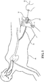
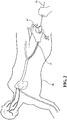
- the present disclosure is generally directed to medical valve assemblies of the type used to introduce and withdrawal a medical device (i.e., a guide wire, catheter, stent, filter, etc.) into a body vessel of a patient.
- a medical device i.e., a guide wire, catheter, stent, filter, etc.
- each of the medical valve assemblies of the present disclosure incorporate a variable seal arrangement and a manually-operable actuator for controlling an entry dimension of the variable seal arrangement.
- each medical valve assembly 10, 10' is of the type for use with a medical device 12, such as a guide wire, catheter, stent, filter, vessel occlusion device, or the like.
- a medical device 12 such as a guide wire, catheter, stent, filter, vessel occlusion device, or the like.
- a user can manually actuate or interact with the medical valve assembly to effectuate a variable seal with variety of different sized medical devices 12.
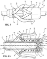
- the medical valve assemblies 10, 10' each include a tube 20 extending between a first tube end 22 and a second tube end 24 to define a passageway 26 extending longitudinally along an axis A between the ends 22, 24, with the passageway 26 being sized to receive a variety of differently sized medical devices 12.
- the first tube end 22 is a distal tube end and the second tube end is a proximal tube end 24.
- a plunger plate 28 extends radially from the second tube end 24 to define an outer plunger plate surface 30 extending in spaced and parallel relationship to the axis A.
- a valve housing 32 is disposed in surrounding relationship with the tube 20 about the second tube end 24 and extends from a first valve housing end 34 to a second valve housing end 36 to overlay the outer plunger plate surface 30.
- the first valve housing end 34 is a distal valve housing end and the second valve housing end 36 is a proximal valve housing end 36.
- the valve housing 32 is disposed in spaced and parallel relationship with the tube 20 between the first valve housing end 34 and the plunger plate 28.
- the valve housing 32 includes a flange 38 extending radially inwardly from the second valve housing end 36.
- the flange 38 is disposed in spaced relationship with the plunger plate 28 to define a distance dimension D, as well as a cavity 40, extending therebetween.
- the flange 38 also defines an opening 42 aligned on the axis A and that is sized to receive a variety of differently sized medical devices 12.
- An elastomeric seal 44 is installed in the cavity 40 and normally is pre-loaded or compressed between the plunger plate 28 and the flange 38. The elastomeric seal 44 is used to establish a variable seal of the medical valve assembly 10, 10'.
- one of the valve housing 32 or the tube 20 is axially movable relative to the other to vary the distance dimension D between the plunger plate 28 and the flange 38 for effectuating an adjustment of an inner diameter 46 of the elastomeric seal 44.
- the axial movement of one of the valve housing 32 or the tube 20 relative to the other results in a change in the compression load exerted on the elastomeric seal 44 which, in turn, allows the inner diameter 46 of the elastomeric seal 44 to be varied or adjusted in size.
- a compression member 48, 54 is disposed within the valve housing 32 and is compressed against the plunger plate 28 for normally closing or decreasing the inner diameter 46 to establish a closed position of the elastomeric seal 44.
- the compression member 48, 54 is arranged to effectuate a closing or decreasing of the inner diameter 46 of the elastomeric seal 44 to establish a closed condition of the medical valve assembly 10, 10'.
- the elastomeric seal 44 In its closed condition, the elastomeric seal 44 completely isolates or seals the opening 42 of the valve housing 32 from the passageway 26 of the tube 20.
- valve housing 32 or the tube 20 is then axially movable relative to the other to alter a distance D between the flange 38 and the plunger plate 28 and shift the medical valve assembly 10, 10' from the closed condition to an open/operative condition.
- the altered or varied distance D between the flange 38 and the plunger plate 28 allows the elastomeric seal 44 to expand, and as a result, the inner diameter 46 of the elastomeric seal 44 is expanded or increased to move the elastomeric seal 44 from its closed position to an open position.
- the medical device 12 With the elastomeric seal 44 in its open position, the medical device 12 is positioned to be inserted serially through the opening 42, the inner diameter 46 of the elastomeric seal 44 and the passageway 26 of the medical valve assembly 10.
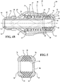
- the compression member 48, 54 comprises a coil spring 48 radially disposed between the valve housing 32 and the tube 20 and compressed between the first valve housing end 34 and the plunger plate 28.
- a disk 50 is slidably disposed around the tube 20 and interconnected to the first valve housing end 34 to establish a shoulder 52 extending radially inward from the valve housing 32 and which is disposed in engagement with the coil spring 48.
- the coil spring 48 acts to bias the valve housing 32 towards the first tube end 22 for compressing the elastomeric seal 44 between the flange 38 and the plunger plate 28 and normally position the elastomeric seal 44 in its closed position.
- the valve housing 32 is then axially movable from the closed position and relative to the tube 20 to increase the distance D between the flange 38 and the plunger plate 28.
- the increased distance D allows the elastomeric seal 44 to expand in an increased area of the cavity 40 disposed between the flange 38 and the plunger plate 28, and as a result, the inner diameter 46 of the elastomeric seal 44 is expanded or increased, thereby opening the elastomeric seal 44.
- the result is the establishment of the open condition of the medical valve assembly 10.
- the compression member 48, 54 also comprises a coil spring 48 radially disposed between the valve housing 32 and the tube 20 and compressed between the first valve housing end 34 and the plunger plate 28.
- a coil spring 48 radially disposed between the valve housing 32 and the tube 20 and compressed between the first valve housing end 34 and the plunger plate 28.
- the valve housing 32 defines a shoulder 52 extending radially inward from the first valve housing end 34 and slidably disposed around the tube 20.
- the shoulder 52 is disposed in engagement with the coil spring 48, and the coil spring 48 acts to bias the valve housing 36 towards the first tube end 22.
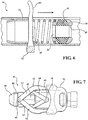
- the compression member 48, 54 additionally includes a leaf spring cage 54 disposed in surrounding relationship with the elastomeric seal 44.
- the leaf spring cage 54 extends between the plunger plate 28 and the flange 38 and is compressed therebetween by way of the compression spring 48.
- the leaf spring cage 54 includes a plurality of struts 56 each extending axially along the leaf spring cage 54 and configured to fold radially inward towards the elastomeric seal 44 when the valve housing 36 is axially biased towards the first tube end 22 by the compression spring 48. As a result, the distance D between the plunger plate 28 and the flange 38 is decreased, thus causing the elastomeric seal 44 to compress and reduce the inner diameter 46.
- the coil spring 48 and the leaf spring cage 54 interact to compress the elastomeric seal 44 between the flange 38 and the plunger plate 28 and normally position the elastomeric seal 44 in its closed position.
- the medical device 12 engages the elastomeric seal 44 with an insertion force that is transferred or exerted radially outward on the struts 56 of the leaf spring cage 54, causing the leaf spring cage 54 to expand and counteract the biasing force of the coil spring 48.
- the distance between the plunger plate 28 and the flange 38 is increased, allowing the inner diameter 46 of the elastomeric seal 44 to expand or increase and establish the open condition of the medical valve assembly 10'.
- a constrictor band 58 extends around the leaf spring cage 54 to prevent the plurality of struts 56 from engaging the valve housing 32 when the leaf spring cage 54 is expanded by the insertion force of the medical device 12.
- the first embodiment of the medical valve assembly 10 includes a manual actuator 62 which can be connected to the valve housing 32 for allowing a user to interact with the medical valve assembly 10 and vary a size of the inner diameter 46 of the elastomeric seal 44.
- the user can interact with the manual actuator 62 to overcome the bias of the compression member 48 and move the valve housing 32 relative to the tube 20 along the axis A towards the second tube end 24.
- the manual actuator 62 allows the user to manually establish the open condition of the medical valve assembly 10.
- the manual actuator 62 can include a trigger arm 60 extending radially from the valve housing 32. In this situation, the user can pull back on the trigger arm 60 to establish the open condition of the medical valve assembly 10. In other words, a user can pull back the trigger arm 60 to vary the bias on the plunger plate 28.
- the manual actuator 62 can include a pair of lever arms 63 interconnected between the tube 20 and the valve housing 32 by way of a pair of lever linkages 64.
- each lever arm 63 includes a first pivot 66 extending radially from the tube 20 and each lever linkage 64 includes a second pivot 68 extending radially from the valve housing 32.
- the pair of lever arms 63 are pivotably connected to the tube 20 by the first pivots 66 and the pair of lever linkages 64 are pivotably connected to the valve housing by the second pivots 68 with each of the lever linkages 64 extending from the respective second pivot 68 to engage one of the respective lever arms 63.
- each of the lever arms 63 can also define a track 70 for receipt of the respective lever linkage 64 when the lever linkages 64 are disposed in abutting relationship with the lever arms 63.
- This arrangement of the lever arms 63 and the lever linkages 64 allows the user to squeeze or compress the pair of lever arms 63 with a specific force to axially advance the valve housing 32 by way of the lever linkages 64.
- the transferred force effectuates the increase in the distance D between the plunger plate 28 and the flange 38, and thus the increase in the inner diameter 46 of the elastomeric seal 44.
- a user can radially squeeze or compress the lever arms 63 to release compression on the elastomeric seal 44 and increase the inner diameter 46 of the elastomeric seal 44 from the closed condition to a desired size of the inner diameter 46 based on an amount of radial squeeze.
- each lever arm 63 can be interconnected between the tube 20 and the valve housing 32 by way of a pair of plates 65.
- each lever arm 63 includes a plate 65 which extends radially therefrom and which defines a cam slot 67 for receiving the second pivot 68 extending radially from the valve housing 32.
- This arrangement of the lever arms 63 and the plates 65 allows the user to squeeze or compress the pair of lever arms 63 with a specific force to slide the second pivot 68 along the cam slots 67 and axially advance the valve housing 32 by way of the plates 65.
- the transferred force effectuates the increase in the distance D between the plunger plate 28 and the flange 38, and thus the increase in the inner diameter 46 of the elastomeric seal 44.
- a user can radially squeeze or compress the lever arms 63 to release compression on the elastomeric seal 44 and increase the inner diameter 46 of the elastomeric seal 44 from the closed condition to a desired size of the inner diameter 46 based on an amount of radial squeeze.
- a detachable cap 72 can be snapped or disposed over the second valve housing end 36 of the valve housing 32 to hold the pair of lever arms 63 in the radially compressed position when the medical valve assembly 10 is not in use.
- the detachable cap 72 When the detachable cap 72 is in place, it keeps the elastomeric seal 44 in the open position, and thus increases the shelf life by reducing material creep, material sticking, and/or the distorting of the elastomeric seal 44.
- the elastomeric seal 44 can include an inner portion 74 and an outer portion 76 disposed axially outwardly from the inner portion 74.
- the inner portion 74 is made from a first material having a first durometer value and the outer portion 76 is made from a second material having a second durometer value being greater than the first durometer value.
- the elastomeric seal 44 includes an outside portion 76 that is harder than an inside portion 74.
- the outer portion 76 of the elastomeric seal 44 is disposed in compressed relationship with the plunger plate 28 and the flange 38.
- the plunger plate 28 and the flange 38 can include curved portions 78 to improve the retention and compression of the outer portions 76 of the elastomeric seal 44.
- the tube 20 has a tapered portion 80 disposed adjacent the first tube end 22 for fitting a sheath over the tube 20.
- the tube 20 includes threads 82 disposed adjacent the first tube end 22 and a nose cap 84 is threadingly secured to the first tube end 22 for establishing a compression fit of the sheath between the nose cap 84 and the tapered portion 80 of the tube 20.
- a wiper seal can be disposed within the passageway 26 between the elastomeric seal 44 and the first tube end 22 to provide a level of hemostasis around a larger device while the elastomeric seal 44 is opened for insertion of the medical device 12.
- a wiper seal 86 can be incorporated into the elastomeric seal 44 and extends radially inward from one of the outside portions 76. As a result, when the elastomeric seal 44 is inserted in the cavity 40, the wiper seal 86 is disposed adjacent the opening 42 of the valve housing 32.
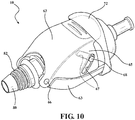
- the medical valve assembly 10' shown in Figures 8 and 9 can be equipped with the compression type manual actuator 62 shown in Figures 3 , 4 and 7 or, in the alternative, the pull-type manual actuator 60 shown in Figure 6 .
- alternative configurations are contemplated for manual actuators that function to controllably vary the relative axial position between two components for proportionately controlling the compression load applied to an elastomeric seal to regulate an internal opening dimension defined thereby.
Landscapes
- Health & Medical Sciences (AREA)
- Life Sciences & Earth Sciences (AREA)
- Heart & Thoracic Surgery (AREA)
- Public Health (AREA)
- Biomedical Technology (AREA)
- Engineering & Computer Science (AREA)
- Animal Behavior & Ethology (AREA)
- General Health & Medical Sciences (AREA)
- Veterinary Medicine (AREA)
- Surgery (AREA)
- Hematology (AREA)
- Pulmonology (AREA)
- Anesthesiology (AREA)
- Physics & Mathematics (AREA)
- Nuclear Medicine, Radiotherapy & Molecular Imaging (AREA)
- Optics & Photonics (AREA)
- Pathology (AREA)
- Radiology & Medical Imaging (AREA)
- Biophysics (AREA)
- Medical Informatics (AREA)
- Molecular Biology (AREA)
- Infusion, Injection, And Reservoir Apparatuses (AREA)
Priority Applications (1)
| Application Number | Priority Date | Filing Date | Title |
|---|---|---|---|
| PL15175941T PL2965685T3 (pl) | 2014-07-09 | 2015-07-08 | Zawór medyczny ze zmienną średnicą uszczelnienia |
Applications Claiming Priority (1)
| Application Number | Priority Date | Filing Date | Title |
|---|---|---|---|
| US14/326,593 US9616213B2 (en) | 2014-07-09 | 2014-07-09 | Medical valve with a variable diameter seal |
Publications (2)
| Publication Number | Publication Date |
|---|---|
| EP2965685A1 EP2965685A1 (en) | 2016-01-13 |
| EP2965685B1 true EP2965685B1 (en) | 2018-09-19 |
Family
ID=53717882
Family Applications (1)
| Application Number | Title | Priority Date | Filing Date |
|---|---|---|---|
| EP15175941.2A Active EP2965685B1 (en) | 2014-07-09 | 2015-07-08 | Medical valve with a variable diameter seal |
Country Status (8)
| Country | Link |
|---|---|
| US (2) | US9616213B2 (pl) |
| EP (1) | EP2965685B1 (pl) |
| AU (1) | AU2015203707B2 (pl) |
| CA (1) | CA2895718C (pl) |
| DK (1) | DK2965685T3 (pl) |
| ES (1) | ES2701834T3 (pl) |
| PL (1) | PL2965685T3 (pl) |
| PT (1) | PT2965685T (pl) |
Families Citing this family (30)
| Publication number | Priority date | Publication date | Assignee | Title |
|---|---|---|---|---|
| WO2005094283A2 (en) | 2004-03-25 | 2005-10-13 | Hauser David L | Vascular filter device |
| WO2013167717A1 (en) * | 2012-05-09 | 2013-11-14 | EON Surgical Ltd. | Laparoscopic port |
| EP3821830B1 (en) | 2012-09-24 | 2024-10-16 | Inari Medical, Inc. | Device for treating vascular occlusion |
| US8784434B2 (en) | 2012-11-20 | 2014-07-22 | Inceptus Medical, Inc. | Methods and apparatus for treating embolism |
| WO2015061365A1 (en) | 2013-10-21 | 2015-04-30 | Inceptus Medical, Llc | Methods and apparatus for treating embolism |
| CA2939315C (en) | 2014-06-09 | 2018-09-11 | Inceptus Medical, Llc | Retraction and aspiration device for treating embolism and associated systems and methods |
| US10881846B2 (en) | 2014-07-09 | 2021-01-05 | Freudenberg Medical, Llc | Medical valve with a variable diameter seal |
| AU2016202012B2 (en) * | 2015-04-23 | 2017-12-07 | Freudenberg Medical, Llc | An automatic medical valve with a variable diameter seal |
| US9884175B2 (en) | 2015-04-23 | 2018-02-06 | Freudenberg Medical, Llc | Automatic medical valve with a variable diameter seal |
| US11207512B2 (en) | 2015-04-23 | 2021-12-28 | Freudenberg Medical, Llc | Automatic medical valve with a variable diameter seal |
| US10342571B2 (en) | 2015-10-23 | 2019-07-09 | Inari Medical, Inc. | Intravascular treatment of vascular occlusion and associated devices, systems, and methods |
| US9700332B2 (en) | 2015-10-23 | 2017-07-11 | Inari Medical, Inc. | Intravascular treatment of vascular occlusion and associated devices, systems, and methods |
| EP4233744A3 (en) | 2015-10-23 | 2023-11-01 | Inari Medical, Inc. | Device for intravascular treatment of vascular occlusion |
| JP2018537229A (ja) | 2015-12-18 | 2018-12-20 | イナリ メディカル, インコーポレイテッド | カテーテルシャフト並びに関連する装置、システム、及び方法 |
| US10183145B2 (en) | 2016-02-24 | 2019-01-22 | Incept, Llc | Enhanced flexibility neurovascular catheter |
| ES2988912T3 (es) | 2016-10-24 | 2024-11-22 | Inari Medical Inc | Dispositivos para el tratamiento de oclusión vascular |
| EP3606402B1 (en) * | 2017-06-16 | 2023-07-05 | Freudenberg Medical, LLC | A medical valve with a variable diameter seal |
| WO2019050765A1 (en) | 2017-09-06 | 2019-03-14 | Inari Medical, Inc. | HEMOSTATIC VALVES AND METHODS OF USE |
| US11154314B2 (en) | 2018-01-26 | 2021-10-26 | Inari Medical, Inc. | Single insertion delivery system for treating embolism and associated systems and methods |
| AU2019201362B2 (en) * | 2018-04-30 | 2024-10-31 | Freudenberg Medical, Llc | A medical valve with a variable diameter seal |
| DK3836855T3 (en) | 2018-08-13 | 2024-11-18 | Inari Medical Inc | System for treating embolism and associated devices and methods |
| US11766539B2 (en) | 2019-03-29 | 2023-09-26 | Incept, Llc | Enhanced flexibility neurovascular catheter |
| WO2021076954A1 (en) | 2019-10-16 | 2021-04-22 | Inari Medical, Inc. | Systems, devices, and methods for treating vascular occlusions |
| US20210315598A1 (en) | 2019-12-18 | 2021-10-14 | Imperative Care, Inc. | Methods of placing large bore aspiration catheters |
| US20230248502A1 (en) | 2019-12-18 | 2023-08-10 | Imperative Care, Inc. | Sterile field clot capture module for use in thrombectomy system |
| EP4463083A4 (en) | 2022-01-11 | 2025-12-03 | Inari Medical Inc | DEVICES FOR REMOVING CLOT MATERIAL FROM INTRAVASCULARLY IMPLANTED DEVICES, AND ASSOCIATED SYSTEMS AND METHODS |
| DE102022133756A1 (de) | 2022-12-16 | 2024-06-27 | Qatna Medical GmbH | Verbindungsmechanismus zur lösbaren fluiddichten Verbindung von zwei medizinischen Geräten |
| AU2024207180A1 (en) | 2023-01-09 | 2025-07-17 | Inari Medical, Inc. | Catheter for use with clot treatment systems |
| US12171917B1 (en) | 2024-01-08 | 2024-12-24 | Imperative Care, Inc. | Devices for blood capture and reintroduction during aspiration procedure |
| US12465382B1 (en) | 2024-05-10 | 2025-11-11 | Inari Medical, Inc. | Mechanical thrombectomy assemblies with relief features, and associated devices, systems, and methods |
Family Cites Families (14)
| Publication number | Priority date | Publication date | Assignee | Title |
|---|---|---|---|---|
| US5127626A (en) | 1989-10-31 | 1992-07-07 | Applied Vascular Devices, Inc. | Apparatus for sealing around members extending therethrough |
| US5395349A (en) | 1991-12-13 | 1995-03-07 | Endovascular Technologies, Inc. | Dual valve reinforced sheath and method |
| US5407433A (en) | 1993-02-10 | 1995-04-18 | Origin Medsystems, Inc. | Gas-tight seal accommodating surgical instruments with a wide range of diameters |
| US6458103B1 (en) | 1998-10-23 | 2002-10-01 | Scimed Life Systems, Inc. | Axially activated hemostasis valve with lumen size selection |
| JP2000316986A (ja) * | 1999-05-07 | 2000-11-21 | Goodman Co Ltd | Yコネクタ |
| US6572590B1 (en) | 2000-07-13 | 2003-06-03 | Merit Medical Systems, Inc. | Adjustable quick-release valve with toggle capability |
| GB0104843D0 (en) | 2001-02-27 | 2001-04-18 | Oxford Instr Analytical Ltd | Detection system |
| US20040178586A1 (en) | 2003-02-20 | 2004-09-16 | Biotronik Gmbh & Co. Kg | Sealing element |
| DE602004031974D1 (de) | 2003-12-11 | 2011-05-05 | Cook Inc | Hämostaseventilanordnung |
| US7967790B2 (en) | 2009-09-01 | 2011-06-28 | Pacesetter, Inc. | Hemostasis valve with iris seal |
| US8025641B2 (en) | 2009-12-18 | 2011-09-27 | Tyco Healthcare Group Lp | Powered variable seal diameter trocar employing a winepress mechanism |
| DE202010006133U1 (de) | 2010-04-22 | 2011-09-07 | Jotec Gmbh | Einrichtung zum Einführen von Kathetern oder endoskopischen Vorrichtungen in eine Körperhöhle |
| US9440059B2 (en) | 2011-03-18 | 2016-09-13 | Cook Medical Technologies Llc | Adjustable diameter hemostatic valve |
| EP2540338B1 (en) | 2011-06-03 | 2015-09-16 | Cook Medical Technologies LLC | Hemostatic valve with multi-layer valve structure |
-
2014
- 2014-07-09 US US14/326,593 patent/US9616213B2/en active Active
-
2015
- 2015-06-25 CA CA2895718A patent/CA2895718C/en active Active
- 2015-07-02 AU AU2015203707A patent/AU2015203707B2/en active Active
- 2015-07-08 EP EP15175941.2A patent/EP2965685B1/en active Active
- 2015-07-08 ES ES15175941T patent/ES2701834T3/es active Active
- 2015-07-08 PL PL15175941T patent/PL2965685T3/pl unknown
- 2015-07-08 PT PT15175941T patent/PT2965685T/pt unknown
- 2015-07-08 DK DK15175941.2T patent/DK2965685T3/en active
-
2017
- 2017-04-10 US US15/483,089 patent/US20170274197A1/en not_active Abandoned
Non-Patent Citations (1)
| Title |
|---|
| None * |
Also Published As
| Publication number | Publication date |
|---|---|
| US20170274197A1 (en) | 2017-09-28 |
| CA2895718A1 (en) | 2016-01-09 |
| ES2701834T3 (es) | 2019-02-26 |
| DK2965685T3 (en) | 2018-11-12 |
| CA2895718C (en) | 2022-08-30 |
| PT2965685T (pt) | 2018-12-18 |
| AU2015203707B2 (en) | 2019-05-30 |
| PL2965685T3 (pl) | 2019-05-31 |
| US20160008591A1 (en) | 2016-01-14 |
| EP2965685A1 (en) | 2016-01-13 |
| AU2015203707A1 (en) | 2016-01-28 |
| US9616213B2 (en) | 2017-04-11 |
Similar Documents
| Publication | Publication Date | Title |
|---|---|---|
| EP2965685B1 (en) | Medical valve with a variable diameter seal | |
| US10881846B2 (en) | Medical valve with a variable diameter seal | |
| US10143828B2 (en) | Medical valve with a variable diameter seal | |
| EP4039317B1 (en) | An automatic medical valve with a variable diameter seal | |
| US7967790B2 (en) | Hemostasis valve with iris seal | |
| EP2101859B1 (en) | Valve assembly | |
| EP2540338B1 (en) | Hemostatic valve with multi-layer valve structure | |
| EP1691884B1 (en) | Hemostatic valve assembly | |
| US11207512B2 (en) | Automatic medical valve with a variable diameter seal | |
| WO2018132758A1 (en) | Catheter valves | |
| AU2020383316B2 (en) | Pressure-driven flow rate control valves | |
| AU2018250718B2 (en) | A medical valve with a variable diameter seal | |
| EP3563901B1 (en) | A medical valve with a variable diameter seal | |
| AU2016202012B2 (en) | An automatic medical valve with a variable diameter seal | |
| US20120310178A1 (en) | Valve assembly | |
| HK1250495A1 (zh) | 带有阀的导管装置及相关方法 |
Legal Events
| Date | Code | Title | Description |
|---|---|---|---|
| PUAI | Public reference made under article 153(3) epc to a published international application that has entered the european phase |
Free format text: ORIGINAL CODE: 0009012 |
|
| AK | Designated contracting states |
Kind code of ref document: A1 Designated state(s): AL AT BE BG CH CY CZ DE DK EE ES FI FR GB GR HR HU IE IS IT LI LT LU LV MC MK MT NL NO PL PT RO RS SE SI SK SM TR |
|
| AX | Request for extension of the european patent |
Extension state: BA ME |
|
| 17P | Request for examination filed |
Effective date: 20160311 |
|
| RBV | Designated contracting states (corrected) |
Designated state(s): AL AT BE BG CH CY CZ DE DK EE ES FI FR GB GR HR HU IE IS IT LI LT LU LV MC MK MT NL NO PL PT RO RS SE SI SK SM TR |
|
| 17Q | First examination report despatched |
Effective date: 20160825 |
|
| STAA | Information on the status of an ep patent application or granted ep patent |
Free format text: STATUS: EXAMINATION IS IN PROGRESS |
|
| GRAP | Despatch of communication of intention to grant a patent |
Free format text: ORIGINAL CODE: EPIDOSNIGR1 |
|
| STAA | Information on the status of an ep patent application or granted ep patent |
Free format text: STATUS: GRANT OF PATENT IS INTENDED |
|
| INTG | Intention to grant announced |
Effective date: 20180328 |
|
| GRAS | Grant fee paid |
Free format text: ORIGINAL CODE: EPIDOSNIGR3 |
|
| GRAA | (expected) grant |
Free format text: ORIGINAL CODE: 0009210 |
|
| STAA | Information on the status of an ep patent application or granted ep patent |
Free format text: STATUS: THE PATENT HAS BEEN GRANTED |
|
| AK | Designated contracting states |
Kind code of ref document: B1 Designated state(s): AL AT BE BG CH CY CZ DE DK EE ES FI FR GB GR HR HU IE IS IT LI LT LU LV MC MK MT NL NO PL PT RO RS SE SI SK SM TR |
|
| REG | Reference to a national code |
Ref country code: GB Ref legal event code: FG4D |
|
| REG | Reference to a national code |
Ref country code: CH Ref legal event code: EP |
|
| REG | Reference to a national code |
Ref country code: CH Ref legal event code: NV Representative=s name: INTELLECTUAL PROPERTY SERVICES GMBH, CH Ref country code: AT Ref legal event code: REF Ref document number: 1042295 Country of ref document: AT Kind code of ref document: T Effective date: 20181015 |
|
| REG | Reference to a national code |
Ref country code: IE Ref legal event code: FG4D |
|
| REG | Reference to a national code |
Ref country code: DE Ref legal event code: R096 Ref document number: 602015016490 Country of ref document: DE |
|
| REG | Reference to a national code |
Ref country code: NO Ref legal event code: T2 Effective date: 20180919 |
|
| REG | Reference to a national code |
Ref country code: DK Ref legal event code: T3 Effective date: 20181106 |
|
| REG | Reference to a national code |
Ref country code: RO Ref legal event code: EPE |
|
| REG | Reference to a national code |
Ref country code: NL Ref legal event code: FP |
|
| REG | Reference to a national code |
Ref country code: PT Ref legal event code: SC4A Ref document number: 2965685 Country of ref document: PT Date of ref document: 20181218 Kind code of ref document: T Free format text: AVAILABILITY OF NATIONAL TRANSLATION Effective date: 20181211 |
|
| REG | Reference to a national code |
Ref country code: SE Ref legal event code: TRGR |
|
| PG25 | Lapsed in a contracting state [announced via postgrant information from national office to epo] |
Ref country code: LT Free format text: LAPSE BECAUSE OF FAILURE TO SUBMIT A TRANSLATION OF THE DESCRIPTION OR TO PAY THE FEE WITHIN THE PRESCRIBED TIME-LIMIT Effective date: 20180919 Ref country code: RS Free format text: LAPSE BECAUSE OF FAILURE TO SUBMIT A TRANSLATION OF THE DESCRIPTION OR TO PAY THE FEE WITHIN THE PRESCRIBED TIME-LIMIT Effective date: 20180919 Ref country code: FI Free format text: LAPSE BECAUSE OF FAILURE TO SUBMIT A TRANSLATION OF THE DESCRIPTION OR TO PAY THE FEE WITHIN THE PRESCRIBED TIME-LIMIT Effective date: 20180919 Ref country code: GR Free format text: LAPSE BECAUSE OF FAILURE TO SUBMIT A TRANSLATION OF THE DESCRIPTION OR TO PAY THE FEE WITHIN THE PRESCRIBED TIME-LIMIT Effective date: 20181220 Ref country code: BG Free format text: LAPSE BECAUSE OF FAILURE TO SUBMIT A TRANSLATION OF THE DESCRIPTION OR TO PAY THE FEE WITHIN THE PRESCRIBED TIME-LIMIT Effective date: 20181219 |
|
| REG | Reference to a national code |
Ref country code: LT Ref legal event code: MG4D |
|
| REG | Reference to a national code |
Ref country code: ES Ref legal event code: FG2A Ref document number: 2701834 Country of ref document: ES Kind code of ref document: T3 Effective date: 20190226 |
|
| PG25 | Lapsed in a contracting state [announced via postgrant information from national office to epo] |
Ref country code: LV Free format text: LAPSE BECAUSE OF FAILURE TO SUBMIT A TRANSLATION OF THE DESCRIPTION OR TO PAY THE FEE WITHIN THE PRESCRIBED TIME-LIMIT Effective date: 20180919 Ref country code: AL Free format text: LAPSE BECAUSE OF FAILURE TO SUBMIT A TRANSLATION OF THE DESCRIPTION OR TO PAY THE FEE WITHIN THE PRESCRIBED TIME-LIMIT Effective date: 20180919 Ref country code: HR Free format text: LAPSE BECAUSE OF FAILURE TO SUBMIT A TRANSLATION OF THE DESCRIPTION OR TO PAY THE FEE WITHIN THE PRESCRIBED TIME-LIMIT Effective date: 20180919 |
|
| PG25 | Lapsed in a contracting state [announced via postgrant information from national office to epo] |
Ref country code: EE Free format text: LAPSE BECAUSE OF FAILURE TO SUBMIT A TRANSLATION OF THE DESCRIPTION OR TO PAY THE FEE WITHIN THE PRESCRIBED TIME-LIMIT Effective date: 20180919 Ref country code: IS Free format text: LAPSE BECAUSE OF FAILURE TO SUBMIT A TRANSLATION OF THE DESCRIPTION OR TO PAY THE FEE WITHIN THE PRESCRIBED TIME-LIMIT Effective date: 20190119 |
|
| PG25 | Lapsed in a contracting state [announced via postgrant information from national office to epo] |
Ref country code: SK Free format text: LAPSE BECAUSE OF FAILURE TO SUBMIT A TRANSLATION OF THE DESCRIPTION OR TO PAY THE FEE WITHIN THE PRESCRIBED TIME-LIMIT Effective date: 20180919 Ref country code: SM Free format text: LAPSE BECAUSE OF FAILURE TO SUBMIT A TRANSLATION OF THE DESCRIPTION OR TO PAY THE FEE WITHIN THE PRESCRIBED TIME-LIMIT Effective date: 20180919 |
|
| REG | Reference to a national code |
Ref country code: DE Ref legal event code: R097 Ref document number: 602015016490 Country of ref document: DE |
|
| PLBE | No opposition filed within time limit |
Free format text: ORIGINAL CODE: 0009261 |
|
| STAA | Information on the status of an ep patent application or granted ep patent |
Free format text: STATUS: NO OPPOSITION FILED WITHIN TIME LIMIT |
|
| 26N | No opposition filed |
Effective date: 20190620 |
|
| PG25 | Lapsed in a contracting state [announced via postgrant information from national office to epo] |
Ref country code: SI Free format text: LAPSE BECAUSE OF FAILURE TO SUBMIT A TRANSLATION OF THE DESCRIPTION OR TO PAY THE FEE WITHIN THE PRESCRIBED TIME-LIMIT Effective date: 20180919 |
|
| PG25 | Lapsed in a contracting state [announced via postgrant information from national office to epo] |
Ref country code: MC Free format text: LAPSE BECAUSE OF FAILURE TO SUBMIT A TRANSLATION OF THE DESCRIPTION OR TO PAY THE FEE WITHIN THE PRESCRIBED TIME-LIMIT Effective date: 20180919 |
|
| PG25 | Lapsed in a contracting state [announced via postgrant information from national office to epo] |
Ref country code: TR Free format text: LAPSE BECAUSE OF FAILURE TO SUBMIT A TRANSLATION OF THE DESCRIPTION OR TO PAY THE FEE WITHIN THE PRESCRIBED TIME-LIMIT Effective date: 20180919 |
|
| PG25 | Lapsed in a contracting state [announced via postgrant information from national office to epo] |
Ref country code: LU Free format text: LAPSE BECAUSE OF NON-PAYMENT OF DUE FEES Effective date: 20190708 |
|
| PG25 | Lapsed in a contracting state [announced via postgrant information from national office to epo] |
Ref country code: CY Free format text: LAPSE BECAUSE OF FAILURE TO SUBMIT A TRANSLATION OF THE DESCRIPTION OR TO PAY THE FEE WITHIN THE PRESCRIBED TIME-LIMIT Effective date: 20180919 |
|
| REG | Reference to a national code |
Ref country code: AT Ref legal event code: UEP Ref document number: 1042295 Country of ref document: AT Kind code of ref document: T Effective date: 20180919 |
|
| PG25 | Lapsed in a contracting state [announced via postgrant information from national office to epo] |
Ref country code: MT Free format text: LAPSE BECAUSE OF FAILURE TO SUBMIT A TRANSLATION OF THE DESCRIPTION OR TO PAY THE FEE WITHIN THE PRESCRIBED TIME-LIMIT Effective date: 20180919 Ref country code: HU Free format text: LAPSE BECAUSE OF FAILURE TO SUBMIT A TRANSLATION OF THE DESCRIPTION OR TO PAY THE FEE WITHIN THE PRESCRIBED TIME-LIMIT; INVALID AB INITIO Effective date: 20150708 |
|
| PG25 | Lapsed in a contracting state [announced via postgrant information from national office to epo] |
Ref country code: MK Free format text: LAPSE BECAUSE OF FAILURE TO SUBMIT A TRANSLATION OF THE DESCRIPTION OR TO PAY THE FEE WITHIN THE PRESCRIBED TIME-LIMIT Effective date: 20180919 |
|
| PGFP | Annual fee paid to national office [announced via postgrant information from national office to epo] |
Ref country code: PT Payment date: 20230620 Year of fee payment: 9 Ref country code: CZ Payment date: 20230621 Year of fee payment: 9 |
|
| PGFP | Annual fee paid to national office [announced via postgrant information from national office to epo] |
Ref country code: PL Payment date: 20230627 Year of fee payment: 9 Ref country code: NL Payment date: 20230724 Year of fee payment: 9 |
|
| PGFP | Annual fee paid to national office [announced via postgrant information from national office to epo] |
Ref country code: RO Payment date: 20230703 Year of fee payment: 9 Ref country code: NO Payment date: 20230724 Year of fee payment: 9 Ref country code: ES Payment date: 20230801 Year of fee payment: 9 Ref country code: CH Payment date: 20230801 Year of fee payment: 9 Ref country code: AT Payment date: 20230719 Year of fee payment: 9 |
|
| PGFP | Annual fee paid to national office [announced via postgrant information from national office to epo] |
Ref country code: SE Payment date: 20230721 Year of fee payment: 9 Ref country code: DK Payment date: 20230720 Year of fee payment: 9 Ref country code: BE Payment date: 20230720 Year of fee payment: 9 |
|
| REG | Reference to a national code |
Ref country code: DK Ref legal event code: EBP Effective date: 20240731 |
|
| REG | Reference to a national code |
Ref country code: CH Ref legal event code: PL |
|
| REG | Reference to a national code |
Ref country code: SE Ref legal event code: EUG |
|
| REG | Reference to a national code |
Ref country code: NL Ref legal event code: MM Effective date: 20240801 |
|
| REG | Reference to a national code |
Ref country code: AT Ref legal event code: MM01 Ref document number: 1042295 Country of ref document: AT Kind code of ref document: T Effective date: 20240708 |
|
| PG25 | Lapsed in a contracting state [announced via postgrant information from national office to epo] |
Ref country code: PT Free format text: LAPSE BECAUSE OF NON-PAYMENT OF DUE FEES Effective date: 20250108 |
|
| PG25 | Lapsed in a contracting state [announced via postgrant information from national office to epo] |
Ref country code: RO Free format text: LAPSE BECAUSE OF NON-PAYMENT OF DUE FEES Effective date: 20240708 Ref country code: NL Free format text: LAPSE BECAUSE OF NON-PAYMENT OF DUE FEES Effective date: 20240801 |
|
| PG25 | Lapsed in a contracting state [announced via postgrant information from national office to epo] |
Ref country code: NO Free format text: LAPSE BECAUSE OF NON-PAYMENT OF DUE FEES Effective date: 20240731 |
|
| PG25 | Lapsed in a contracting state [announced via postgrant information from national office to epo] |
Ref country code: CH Free format text: LAPSE BECAUSE OF NON-PAYMENT OF DUE FEES Effective date: 20240731 Ref country code: AT Free format text: LAPSE BECAUSE OF NON-PAYMENT OF DUE FEES Effective date: 20240708 Ref country code: BE Free format text: LAPSE BECAUSE OF NON-PAYMENT OF DUE FEES Effective date: 20240731 |
|
| PG25 | Lapsed in a contracting state [announced via postgrant information from national office to epo] |
Ref country code: CZ Free format text: LAPSE BECAUSE OF NON-PAYMENT OF DUE FEES Effective date: 20240708 |
|
| REG | Reference to a national code |
Ref country code: BE Ref legal event code: MM Effective date: 20240731 |
|
| PG25 | Lapsed in a contracting state [announced via postgrant information from national office to epo] |
Ref country code: DK Free format text: LAPSE BECAUSE OF NON-PAYMENT OF DUE FEES Effective date: 20240731 |
|
| REG | Reference to a national code |
Ref country code: ES Ref legal event code: FD2A Effective date: 20250829 |
|
| PG25 | Lapsed in a contracting state [announced via postgrant information from national office to epo] |
Ref country code: ES Free format text: LAPSE BECAUSE OF NON-PAYMENT OF DUE FEES Effective date: 20240709 |
|
| PGFP | Annual fee paid to national office [announced via postgrant information from national office to epo] |
Ref country code: DE Payment date: 20250730 Year of fee payment: 11 |
|
| PG25 | Lapsed in a contracting state [announced via postgrant information from national office to epo] |
Ref country code: SE Free format text: LAPSE BECAUSE OF NON-PAYMENT OF DUE FEES Effective date: 20240709 |
|
| PGFP | Annual fee paid to national office [announced via postgrant information from national office to epo] |
Ref country code: IT Payment date: 20250729 Year of fee payment: 11 |
|
| PGFP | Annual fee paid to national office [announced via postgrant information from national office to epo] |
Ref country code: GB Payment date: 20250725 Year of fee payment: 11 |
|
| PGFP | Annual fee paid to national office [announced via postgrant information from national office to epo] |
Ref country code: FR Payment date: 20250729 Year of fee payment: 11 |
|
| PGFP | Annual fee paid to national office [announced via postgrant information from national office to epo] |
Ref country code: IE Payment date: 20250723 Year of fee payment: 11 |