EP2965496B1 - Content based noise suppression - Google Patents
Content based noise suppression Download PDFInfo
- Publication number
- EP2965496B1 EP2965496B1 EP14708428.9A EP14708428A EP2965496B1 EP 2965496 B1 EP2965496 B1 EP 2965496B1 EP 14708428 A EP14708428 A EP 14708428A EP 2965496 B1 EP2965496 B1 EP 2965496B1
- Authority
- EP
- European Patent Office
- Prior art keywords
- signal
- audio signal
- content
- noise
- input audio
- Prior art date
- Legal status (The legal status is an assumption and is not a legal conclusion. Google has not performed a legal analysis and makes no representation as to the accuracy of the status listed.)
- Not-in-force
Links
- 230000001629 suppression Effects 0.000 title description 16
- 230000005236 sound signal Effects 0.000 claims description 135
- 238000000034 method Methods 0.000 claims description 63
- 230000003044 adaptive effect Effects 0.000 claims description 44
- 238000004891 communication Methods 0.000 claims description 38
- 230000001360 synchronised effect Effects 0.000 claims description 21
- 230000004044 response Effects 0.000 claims description 6
- 238000012545 processing Methods 0.000 description 63
- 238000010586 diagram Methods 0.000 description 20
- 238000013500 data storage Methods 0.000 description 14
- 230000001934 delay Effects 0.000 description 9
- 230000006870 function Effects 0.000 description 9
- 230000000694 effects Effects 0.000 description 8
- 238000005516 engineering process Methods 0.000 description 7
- 238000001914 filtration Methods 0.000 description 7
- 239000000872 buffer Substances 0.000 description 6
- 230000008569 process Effects 0.000 description 6
- 230000001413 cellular effect Effects 0.000 description 4
- 238000001514 detection method Methods 0.000 description 4
- 238000012805 post-processing Methods 0.000 description 4
- 230000002238 attenuated effect Effects 0.000 description 3
- 230000003287 optical effect Effects 0.000 description 3
- 238000010276 construction Methods 0.000 description 2
- 238000002592 echocardiography Methods 0.000 description 2
- 238000000605 extraction Methods 0.000 description 2
- 239000000835 fiber Substances 0.000 description 2
- 238000012986 modification Methods 0.000 description 2
- 230000004048 modification Effects 0.000 description 2
- 230000003595 spectral effect Effects 0.000 description 2
- 230000002123 temporal effect Effects 0.000 description 2
- 240000001436 Antirrhinum majus Species 0.000 description 1
- 230000006978 adaptation Effects 0.000 description 1
- 238000004590 computer program Methods 0.000 description 1
- 230000002939 deleterious effect Effects 0.000 description 1
- 238000013461 design Methods 0.000 description 1
- 230000003116 impacting effect Effects 0.000 description 1
- 230000007246 mechanism Effects 0.000 description 1
- 239000003607 modifier Substances 0.000 description 1
- 230000003362 replicative effect Effects 0.000 description 1
- 239000010979 ruby Substances 0.000 description 1
- 229910001750 ruby Inorganic materials 0.000 description 1
- 238000010845 search algorithm Methods 0.000 description 1
- 230000003068 static effect Effects 0.000 description 1
- 238000013179 statistical model Methods 0.000 description 1
- 239000000126 substance Substances 0.000 description 1
- 238000012546 transfer Methods 0.000 description 1
Images


Classifications
-
- G—PHYSICS
- G10—MUSICAL INSTRUMENTS; ACOUSTICS
- G10K—SOUND-PRODUCING DEVICES; METHODS OR DEVICES FOR PROTECTING AGAINST, OR FOR DAMPING, NOISE OR OTHER ACOUSTIC WAVES IN GENERAL; ACOUSTICS NOT OTHERWISE PROVIDED FOR
- G10K11/00—Methods or devices for transmitting, conducting or directing sound in general; Methods or devices for protecting against, or for damping, noise or other acoustic waves in general
- G10K11/16—Methods or devices for protecting against, or for damping, noise or other acoustic waves in general
-
- H—ELECTRICITY
- H04—ELECTRIC COMMUNICATION TECHNIQUE
- H04M—TELEPHONIC COMMUNICATION
- H04M9/00—Arrangements for interconnection not involving centralised switching
- H04M9/08—Two-way loud-speaking telephone systems with means for conditioning the signal, e.g. for suppressing echoes for one or both directions of traffic
- H04M9/082—Two-way loud-speaking telephone systems with means for conditioning the signal, e.g. for suppressing echoes for one or both directions of traffic using echo cancellers
-
- G—PHYSICS
- G10—MUSICAL INSTRUMENTS; ACOUSTICS
- G10L—SPEECH ANALYSIS TECHNIQUES OR SPEECH SYNTHESIS; SPEECH RECOGNITION; SPEECH OR VOICE PROCESSING TECHNIQUES; SPEECH OR AUDIO CODING OR DECODING
- G10L21/00—Speech or voice signal processing techniques to produce another audible or non-audible signal, e.g. visual or tactile, in order to modify its quality or its intelligibility
- G10L21/02—Speech enhancement, e.g. noise reduction or echo cancellation
- G10L21/0208—Noise filtering
- G10L21/0216—Noise filtering characterised by the method used for estimating noise
-
- G—PHYSICS
- G10—MUSICAL INSTRUMENTS; ACOUSTICS
- G10L—SPEECH ANALYSIS TECHNIQUES OR SPEECH SYNTHESIS; SPEECH RECOGNITION; SPEECH OR VOICE PROCESSING TECHNIQUES; SPEECH OR AUDIO CODING OR DECODING
- G10L21/00—Speech or voice signal processing techniques to produce another audible or non-audible signal, e.g. visual or tactile, in order to modify its quality or its intelligibility
- G10L21/02—Speech enhancement, e.g. noise reduction or echo cancellation
- G10L21/0208—Noise filtering
- G10L2021/02082—Noise filtering the noise being echo, reverberation of the speech
Definitions
- the following description is directed to audio signal processing.
- the description is directed to audio noise suppression.
- a mobile device may use voice recognition to allow users to control the mobile device with voice commands.
- voice recognition as well as voice telemetry, users want the mobile device to operate normally in variety of environments, including acoustically-harsh environments.
- noise suppression schemes have been used to reduce or mitigate the deleterious effects of background noise as a user is interacting with a mobile device.
- Frequency selective filtering for instance, can be used to suppress noises associated with certain frequency bands.
- Other noise suppression schemes use statistical models to suppress certain aspects of the captured audio signal that are statistically related to noise or that are statistically unrelated to the intended audio signal.
- Yet other noise suppression schemes use internal signals to cancel noise resulting from sound produced and then sensed (for example, echo noise) by the mobile device.
- Audio Forensics describes a method of cancelling noise from a source such as a television placed on filtering by assimilating an acoustic environment.
- One embodiment is a device to attenuate audio noise, as in claim 1.
- Another embodiment is a method to attenuate audio noise, as in claim 8.
- Still another embodiment is a non-transitory, computer-readable medium storing instructions that, when executed, causes a processor to perform a method, as in claim 13.
- Embodiments relate to systems and methods for suppressing unwanted audio noise in an audio signal received by an electronic device.
- the system suppresses audio noise representing identifiable media content, such as a popular song being played in the background.
- the system may obtain a copy of the media content, generate a copy of the unwanted audio noise from the copy of the media content, and remove the the unwanted audio noise from the audio signal.
- the system determines an acoustic pattern or fingerprint of the unwanted audio noise and uses the pattern to identify the media content (for example, a particular song) represented by the audio noise.
- the identity can be used to search for a media content source, such as a digital recording of the identified song.
- the system can be implemented by a portable computing device, such as a cellular phone.
- the cellular phone can suppress songs or other media content playing in the background during a phone conversation.
- the system can be implemented by a cellular phone with a microphone and a digital music library stored in a memory of the phone.
- the system can extract audio features from the microphone's audio signal to develop an acoustic pattern or fingerprint of that song.
- the developed pattern can then be used to search a database containing song identities indexed by such acoustic patterns to find the song being played by the radio. If a song identity matches the pattern, the phone can then search its music library for a copy of the identified song. Alternatively, the phone could request a copy of the identified song from a server over a network connection.
- the copy of the song can be synchronized to the temporal position of the song as it's played on the radio to suppress the song from the received audio signal.
- a phone having this system would allow a user to operate a phone in areas that were otherwise too acoustically harsh for telephonic conversations, such as outdoor music venues or concert halls.
- the noise suppression system can be implemented by a voice-controlled remote controller that controls a separate media device such as a television (TV) having wireless communication capabilities.
- the controller may receive content information directly from the TV.
- the TV can communicate the active channel being displayed to the remote, and the remote can use that information to access the channel's audio through an Internet connection.
- the TV can send a copy of the broadcast to the remote.
- the remote can, in turn, use the copy of the broadcast to cancel out the audio produce by the TV. This would allow for voice-controlled electronic devices to function with media devices generating audio.
- the disclosed methods, apparatus, and systems may function to improve existing noise suppression techniques.
- audio noise can be found to be substantially deterministic after estimating and/or identifying the content of the audio noise.
- the song can be substantially deterministic if, for example, it is known that a song is being played, what particular song, and the specific timing of the song. If the above content-related information is known or identifiable, a copy of the song or audio signal can be used to attenuate, or cancel, a component of the audio signal corresponding to the song. Suppression of the song in this way may improve the quality of voice recognition or voice communication over the mobile device.
- Examples of a media device include a television, radio, laptop/netbook computer, tablet computer, desktop computer, and the like electronic devices configured to play media content, including audio media content.
- Examples of audio media content include data or signals representing music, video, and other like media having audio.
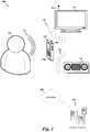
- Figure 1 shows a block diagram of a specific audio configuration 100 including a mobile phone 102 that is configured to suppress noise from one or more media devices.
- the mobile phone 102 has a microphone 104 and an antenna 106.
- the mobile phone 102 can communicate voice and data signals to a network 108 or other electronic devices.
- the network 108 can be a wired or wireless network, and can provide access to one or more content databases 110 storing various content sources, such as music and audio-video data files.
- the network is the Internet.
- a user 112 speaks into the microphone 104 of the mobile phone 102 for voice communication and/or voice recognition, for example, to control the mobile phone 102 or to control other electronic devices communicatively coupled to the mobile phone 102.
- the microphone 104 of the mobile phone 102 captures the user's voice commands 114 to generate an input audio signal.
- the mobile phone 102 in some situations, may be in close proximity to separate media devices, such as a networked-enabled television (TV) 116 or a radio 118. These devices may produce background sounds 120, 122 that act as unwanted background audio noise with respect to the operation of the mobile phone 102.
- TV networked-enabled television
- the network-enabled TV 116 or the radio 118 can be playing stored or streaming music.
- the microphone 104 may capture the voice commands 114 from the user 112 contemporaneously with the background sounds produced by the network-enabled TV 116 or the radio 118. Under such circumstances, the sound from the network-enabled TV 116 or the radio 118 may significantly interfere with the user's voice commands 114 and make conversation or voice recognition difficult for the user.
- Various embodiments are related to suppressing the noise components of the input audio signal.
- the mobile phone 102 can suppress the noise signal more specifically if the content of the noise signal can be identified.
- the mobile phone 102 analyzes the input audio signal to determine whether the input audio signal has an identifiable content, such as a particular song or audio from a television broadcast. For example, one embodiment determines content-identification information (such as song title, album name, artist name, or the like) by extracting features of the input audio signal, and then searching, downloading, streaming, or otherwise accessing a content source.
- the mobile phone 102 can search the content databases 110 to access the content source, where the content source is determined based on matching the source-identification information. Having access to the content source, the mobile phone 102 can obtain a copy of the audio noise ("source signal”), which can be used to specifically attenuate or suppress the audio noise corresponding to the sound produced by the media devices.
- source signal a copy of the audio noise
- the mobile phone 102 may communicate, either directly or over the network 108, with the network-enabled TV 116 and/or the radio 118 to identify the content source.
- the mobile phone 102 may be able to request, for instance, channel information from the network-enabled TV 116, where the network-enabled TV 116 can communicate by using its communication antenna 124. Based on the received channel information, the mobile phone 102 can access a content source from the content databases 110.
- the mobile phone 102 can access the content source from a device (not shown) that is broadcasting the media content to the network-enabled TV 116, for example, by tuning to the identified channel.
- the mobile phone 102 can access the content source from the network-enabled TV 116.
- network-enabled TV 116 can transmit or relay the content source directly to the mobile phone 102.
- the audio processing device 202 includes a processor 204, a microphone 206, a communication interface 208, a data storage device 210, and a memory 212 interconnected by a bus 214. Furthermore, the memory 212 can include an audio signal analyzer module 216, an audio canceller module 218, and a communication module 212. Examples of the audio processing device 202 include any applicable electronic device, such as a mobile computing device, cellular phone, general purpose computer, and the like.
- the processor 204 includes circuitry, such as a microprocessor or microcontroller, configured to execute instructions from memory 212 and to control and operate the microphone 206, the communication interface 208, the data storage device 210, the memory 212, and the bus 214.
- the processor 204 may be a general purpose single- or multi-chip microprocessor (e.g., an ARM), a special purpose microprocessor (e.g., a digital signal processor (DSP)), a microcontroller, a programmable gate array, etc.
- DSP digital signal processor
- a single processor is shown in the audio processing device 202, in an alternative configuration, a combination of processors (e.g., an ARM and DSP) could be used.
- the microphone 206 is configured to capture acoustic sounds and generate an input audio signal in response, as controlled by the processor 204 executing specific instructions from the memory 212.
- Examples of the microphone 206 include any applicable sensor or transducer for converting sound into an electrical audio signal, such as condenser microphones, dynamic microphones, piezoelectric microphones, and the like.
- the microphone 206 is optional, and an input audio signal is, for example, generated from data from the data storage device 210 or the memory 212, or received from the communication interface 208, as will be discussed below with reference to Figure 3 .
- the communication interface 208 includes electronics configured to allow the audio processing device 202 to transmit and receive data, such as data for identifying, retrieving, or accessing the content source.
- the communication interface 208 can be communicatively coupled to a wireless antenna, WLAN/LAN and other types of routers, and like communication devices.
- the data storage device 210 and the memory 212 include mechanisms configured to store information by chemical, magnetic, electrical, optical, or the like means.
- the data storage device 210 and memory 212 can each be a nonvolatile memory device, such as flash memory or a hard-disk drive, or a volatile memory device, such as dynamic-random access memory (DRAM) or static random-access memory (SRAM).
- the processor 204 can access the content source by accessing a content-source database of the data storage device 210.
- Figure 2 shows the data storage device 210 as part of the audio processing device 202.
- the data storage device 210 may be located on a separate device and accessed by communication channels, for example over a network.
- the audio signal analyzer module 216 will be discussed in further detail in connection with Figure 3 .
- the audio signal analyzer module 216 that includes instructions that configure the processor 204 to initiate identification of a content of the input audio signal, to provide access to a corresponding content source, and/or to receive an identified source signal.
- features are extracted from the input audio signal. The extracted features can be used to determine a content identity of media content represented by the input audio signal, and the content identity can be used to access a content source associated with the content identity.
- the audio signal analyzer module 218 will be discussed in further detail in connection with Figures 4 and 5 .
- the audio canceller module 218 that includes instructions that configure the processor 204 to process the input audio signal with the identified source signal to attenuate audio noise.
- the input audio signal is compared with the identified source signal.
- the identified source signal is filtered to account for room acoustics.
- the input audio signal and the identified source signal are synchronized to account for a various delays resulting from computational, communication, and acoustical factors.
- the audio canceller module 218 will be discussed in further detail in connection with Figures 4 and 5 .
- the communication module 220 that includes instructions that configure the processor 204 to control the communication interface 208 to transmit or receive data.
- communication can be initiated between the audio processing device 202 and a separate media device, such as the network-enabled TV 116 of Figure 1 , as discussed below in further detail.
- the processor 204 can execute instructions from memory 212 to receive an input audio signal captured by the microphone 206.
- the input audio signal may contain a voice signal and an audio noise signal.
- the voice signal may represent the user's voice, whereas the audio noise signal may represent sound produced by nearby media devices.
- the processor 204 may execute instructions from the audio signal analyzer module 216 to identify a content of the audio noise signal.
- the processor 204 may then search the data storage device 210 for a content source associated with the identified content. Additionally or alternatively, the processor 204 may execute instructions from the audio signal analyzer and/or communication module 212 to search databases over a network via the communication interface 208.
- the processor 204 may execute instructions from audio canceller module 218 to suppress her attenuate at least part of the audio noise signal by comparing a copy of the noise signal (for example, a filtered or unfiltered identified source signal) to the input audio signal.
- a copy of the noise signal for example, a filtered or unfiltered identified source signal
- a block diagram shows a particular illustrative embodiment of an audio signal analyzer 300 implemented by the audio processing device 202 of Figure 2 .
- the audio signal analyzer 300 can be implemented with computer executable instructions, such as the instructions of the audio signal analyzer module 216, executed by the processor 204.
- the audio signal analyzer 300 of Figure 3 includes an identifier generator 302 configured to receive an input audio signal and to generate content-identification information.
- the content-identification information can include one or more of the artist's name, the content title (name of song, movie, audiobook, etc.), an identification number, and the like indicia of identity.
- the audio signal analyzer 300 also has a source matcher 304 that is configured to receive the content-identification information and to generate an identified source signal.
- the identifier generator 302 of Figure 3 has a feature extractor 306, a content identifier 308, and a content-identity database 310.
- the feature extractor 306 can be implemented by a module including instructions that configure the processor 204 to determine feature information of the input audio signal to determine the content. For example, in operation the feature extractor 306 can analyze the input audio signal to determine an acoustic pattern or fingerprint that can identify or characterize the input audio signal. In one embodiment, the acoustic pattern or fingerprint can be based on performing spectrogram (for example, time-frequency) analysis.
- the content identifier 308 can be implemented by a module including instructions that configure the processor 204 to use the acoustic pattern or fingerprint to search the content-identity database 310 for a content identity of the acoustic pattern or fingerprint.
- the processor 204 can search the content-identity database 310 for content-identification information that corresponds to, or approximately matches, the acoustic pattern or fingerprint.
- the identifier generator 302 provides content-identification information to the source matcher 304.
- the source matcher 304 of Figure 3 includes a source searcher 312, a source database 314, and a source transmitter 316.
- the source searcher 312 can be implemented by a module including instructions that configure the processor 204 to use the content-identification information to search the source database 314 for a content source.
- the processor 204 can search the source database 314 stored on the data storage device 210 (or stored externally and accessed with the communication interface 208) for a content source such as an MP3 file of a song that corresponds to, or approximately matches, the content-identification information.
- the source transmitter 316 can access the content source identified by the source searcher 312 and can generate an identified source signal.
- the source signal can be transmitted as pulse-code modulation (PCM) audio samples, data packets (including compressed or coded data), or the like data formats.
- the source transmitter 316 may optionally include a vocoder/encoder 318 to generate coded audio data packets to be transmitted to the audio processing device 202.
- the source transmitter 316 can be located at a server computing device, and the source signal can be sent to the audio processing device 202 (such as the mobile phone 102 of Figure 1 ) on a data path or a voice path.
- each of the functions of the audio signal analyzer 300 can be performed by the audio processing device 202 of Figure 2 .
- one or more the functions are performed by one or more server computing devices (such as the content databases 110 and other devices connected to the network).
- the audio processing device 202 can use the communication interface 208 to communicate with a server computer over a network.
- the identified source signal may be provided over the network in a streaming-like manner its entirety, or in data blocks, in a download-like manner.
- the audio processing device 202 may receive portions of the identified source signal before it is needed for canceling.
- each of the content-identity database 310 and the source database 314 can be stored electronically on the data storage device 210 or the memory 212 of the audio processing device 202, or it can be stored externally to the audio processing device 202 and accessed over a network.
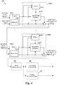
- FIG 4 shows a block diagram of a particular illustrative embodiment of an audio canceller system 400 implemented by the audio processing device 202 of Figure 2 .
- the audio canceller system 400 can be used to suppress multiple audio noise sources.
- the audio canceller system 400 has n synchronization blocks 402(1)-402( n ) (also called “signal synchronizers") and n corresponding audio cancellers 404(1)-405( n ), as well as optional post-processing 406, vocoder 408, and voice recognition 410 blocks.
- the audio canceller system 400 can be implemented with computer executable instructions, such as the instructions of the audio canceller module 218, executed by the processor 204.
- the audio canceller system 400 receives the input audio signal and n identified source signals, one for each of n possible audio noises to be attenuated.
- audio noise 1 can correspond to audio 120 from the network-enabled TV 116
- audio noise 2 can correspond to audio 122 from the radio 118.
- each identified source signals can correspond to a source signal generated by, for example, the audio signal analyzer 300 of Figure 3 .
- the n pairs of synchronization block 402(1)-402( n ) and audio canceller block 404(1)-404( n ) are configured in series such that audio noise 1 is suppressed first, and the resultant processed input audio signal is fed to the audio canceller 2 to suppress the audio noise 2, and so on. It will be appreciated that other applicable configurations can be selected, such as n parallel audio cancellers 404(1)-404( n ).
- the n identified source signals can be provided by n separate source transmitters, such as the one shown in Figure 3 . Additionally or alternatively, the n identified source signals can be generated by the separate media device producing the audio noise.
- the n identified source signals (as well as the input audio signal) can each be provided as PCM audio samples or data packets.
- the n identified source signals are transmitted as coded voice packets and the audio canceller system 400 includes optional vocoders/decoders (not shown) for decoding the signals before providing the signals to the synchronization blocks 402(1)-402( n ).
- each of the audio cancellers 404(1)-404( n ) is associated with a synchronization block 402(1)-402( n ), respectively.
- Each of the synchronization blocks 402(1)-402( n ) can synchronize the input audio signal (or the output of the previous audio canceller) and the corresponding identified source signal.
- the synchronization blocks 402(1)-402( n ) can compensate for timing differences due to processing, communication, and the like sources of delays. Further, the synchronization blocks 402(1)-402( n ) can be used to compensate in errors in determining or estimating the current temporal location of the source that is being played by the media device.
- Each of the synchronization blocks 402(1)-402( n ) can have a corresponding data buffer 416(1)-416( n ), respectively, for providing a delay for synchronization.
- the delay can be tunable in some embodiments.
- the tunable delay can be determined by performing a calibration process. Non-limiting examples of processes for calibrating and tuning the delays can be found in U.S. Provisional Patent Application No. 61/681,474, filed on August 9, 2012 .
- Each of the n audio cancellers 404(1)-404(n) can have one or more adaptive filters 412(1)-412( n ), respectively, configured to filter the corresponding source signal. Filtering can be used to account for variations between the captured audio noise and the source signal. That is, the audio noise captured by the microphone 206 may vary from the source signal because of a number of factors, including the dynamics of the acoustical space (for example, echoes and acoustic dampening, which can vary with microphone 206 and media device locations), dynamics of the speaker/microphone, variations in the content sources(for example, different recording qualities), and the like.
- each of the adaptive filters 412(1)-412( n ) can have one or more tunable filter parameters.
- the filter parameters can be tuned online to model these variations based on the input audio signal and the source signal. For example, when the input audio signal includes, in large part, the sound generated by the media device 1, the error between the output of the adaptive filter 412(1) (the "filtered source signal") and the input audio signal can be used to tune the filter parameters in a manner to reduce the error between the signals. Small error can indicate that the adaptive filter 412(1) is approximately modeling the acoustical effects that modify the audio noise signal, whereas large error indicates that the adaptive filter 412(1) is not modeling the acoustical effects.
- adaptive laws or "update rules” can be used to adjust the filter coefficients.
- adaptive laws based on a gradient method, such as those based on reducing an instantaneous or integral cost, to adjust the tunable filter parameters to reduce the error between the filtered source signal and the input audio signal.
- Other examples include a least-mean-square method, a Lyapunov/stability method, and stochastic methods.
- any suitable recursive, non-recursive, or batch adaptive law can be used to adjust the tunable filter parameters.
- the audio canceller 404(1) receives synchronized copies of the input audio signal and the identified source signal 1.
- the identified source signal 1 can approximate the audio signal driving a speaker that is generating the audio noise.
- the adaptive filter 412(1) can filter the identified source signal to account for acoustical dynamics of the acoustic space, thereby generating a filtered source signal 1 that approximates the audio noise 1 captured by the microphone 206.
- the audio canceller 404(1) compares the synchronized input audio signal to the filtered source signal 1 to attenuate or suppress audio noise 1. As shown, audio canceller 404(1) subtracts the filtered source signal from the input audio signal.
- the audio signal with suppressed noise 1 is then fed to the second synchronization block to suppress audio noise 2, and so on, until the n audio noises have been suppressed from the input audio signal.
- each adaptive filter 412(1)-412( n ) can optionally have a double talk detector (“DTD") 414(1)-414( n ), respectively, to stop or enable adjustment of its filter parameter under certain circumstances.
- DTD double talk detector
- the input audio signal or output of the previous audio canceller
- the corresponding adaptive filter 412( n ) may not adapt properly.
- the adaptive filter 412( n ) may be adapting when additional near-end signals other than the audio noise are present, those additional near-end signals may act as strongly uncorrelated noise with respect to the adaptive law.
- each of the DTDs 414(1)-414( n ) may be used to monitor the input of the corresponding adaptive filter 412(1)-412( n ) and stop or enable adaptation based on the detection of additional near-end signals.
- One such method of the DTDs 414(1)-414( n ) may involve calculating a double-talk detection statistic to determine when the adaptive filter input signal includes additional near-end signals.
- One example double-talk detection statistic is given by the ratio of the source signal power to the corresponding adaptive filter input signal.
- Other applicable doubletalk-detection statistics can be selected.
- the double-talk statistic may be computed in the time domain or in the frequency domain.
- an optional non-linear post-processing block 406 can optionally be included to perform certain types of processing on the signal provided by the echo canceller 404( n ).
- the non-linear post-processing block 406 may remove the residual noise (for example, a non-linear component of the audio noise signal) from the signal leaving the echo canceller 404( n ).
- the non-linear noise component can be removed or attenuated by estimating the non-linear component of the input audio signal and then subtracting (for example, by using spectral subtraction techniques) the estimate from the input audio signal.
- the non-linear post processing block may operate based on the double-talk decisions from the DTDs 414(1)-414( n ). Hence, the double-talk decisions help differentiate between the near-end signal and residual audio noise before the non-linear post processor 204 clips or removes the signal completely.
- the audio signal with suppressed noises 1, ... , n may be provided to a vocoder 408 to encode the audio signal into voice packets. Additionally or alternatively, audio signal with suppressed noises may be provided to a voice recognition block 410 for further audio signal processing.
- the number n of audio cancellers 404(1)-404( n ) can be selected based on various considerations, such as expected noise environments, computing power, real-time constraints, memory, performance, and/or the like considerations. It will be appreciated, however, that other applicable factors can be considered. Likewise, it will be appreciated that the audio canceller system can include any applicable number of synchronization blocks. In some embodiments, the number of these components can vary dynamically with respect to the number of identified noise components as discussed below in connection with Figure 5 .
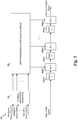
- FIG. 5 shows a block diagram of another particular illustrative embodiment of an audio canceller system 500 implemented by the audio processing device 202 of Figure 2 .
- Elements common to the systems 400, 500 of Figures 4 and 5 share common reference indicia, and only differences between the systems 400, 500 are described herein for the sake of brevity.
- the audio canceller system 500 has n synchronization blocks 402(1)-402( n ), n audio canceller blocks 404(1)-404( n ), a source identifier detector 502, and a reconfigurable canceller enabler 504.
- the source identifier detector 502 receives n identified source signals to determine which of the identified source signal paths are active. For example, the source identifier detector 502 can determine active source signal paths based on the presence of a signal or the level of the energy of the corresponding signal on that path.
- the reconfigurable canceller enabler 504 activates the audio canceller blocks 404(1)-404( n ) corresponding to active identified source signal paths.
- Each active audio canceller block of the audio canceller blocks 404(1)-404( n ) can operate as described above in connection with Figure 4 .
- Each inactive audio canceller block of the audio canceller blocks 404(1)-404( n ), for example, can be configured as a pass-through filter.
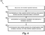
- Figure 6 shows a flow diagram of a method 600 of audio noise suppression according to one embodiment. While the description of the methods which follow focuses on implementation on a personal audio processing device 202, such as a mobile phone, personal audio player, other devices may be configured to perform the method or a variant thereof.
- the methods can be implemented as a software module or collection of modules residing with the non-transitory computer storage, such as RAM, ROM, a hard disk drive, or the like, of a computing device associated with the audio processing device 202.
- One or more processors of the computing device can execute the software module.
- the method 600 includes receiving an input audio signal.
- the audio processing device 202 may receive the input audio signal from the microphone 206 of the audio processing device 202, from the data storage device 210 or the memory 212 device, or received at the communication interface 208.
- the process 600 moves to block 604 wherein a determination is made if the audio input signal includes noise having identifiable content.
- the audio processing device 202 may execute instructions from the audio signal analyzer module 216 to determine feature information of the audio input signal that may be used to identify the content of the audio noise.
- the feature information can be used by the content identifier 308 to determine content identification information.
- the audio processing device 202 can send the feature information to a server over a network for further processing and then receive the content-identification information over the network.
- one or more of the functions of the content identifier 308 and source searcher 312 blocks can be performed on the audio processing device 202 to determine content-identification information.
- One embodiment of a method for implementing the operation of the block 604 is described below in connection with Figure 7A .
- the operation of the block 604 is performed by the executing instructions from the audio signal analyzer module 216 to communicate with a separate media device to determine if the audio input signal has identifiable content.
- the audio processing device 202 can request information from the separate media device regarding whether media device is playing audio media and, if so, content-identification information. In response, the audio processing device 202 may receive content-identification information.
- the method 600 moves to block 606 to access a content source of the identifiable content to obtain a source signal.
- the audio processing device 202 may access the content source or the content source signal via the communication interface 208 or via the memory 212 or data storage device 210.
- the content-identification information obtained in block 604 can be used to locate and access a content source.
- the content source can be used to generate a source signal.
- the method 600 proceeds to block 608 wherein the noise is attenuated based on comparing the source signal to the input audio signal.
- the audio processing device 202 executes instructions of the audio canceller module 218 in memory 212 to attenuate the audio noise in accordance with the audio canceller system shown in Figures 4 or 5 .
- the method 604 determines feature information of the input audio signal.
- the audio processing device 202 executes instructions of the audio signal analyzer module 216 in memory 212 to extract features in accordance with the feature extractor 306 shown in Figure 3 .
- the process 604 then moves to block 704 to provide the feature information to identify the content source.
- the audio processing device 202 executes instructions of the audio signal analyzer module 216 in memory 212 to cause the communication interface 208 to transmit the feature information to a server device over a network for processing by the server device.
- the method 604 proceeds to block 706 for obtaining content-identification information.
- the audio processing device 202 can receive the content-identification information from the server device that received the feature information in performing block 704.
- the audio processing device 202 generates the content-identification information by performing the necessary steps on the processing device 202 instead of communicating with a server device.
- the processor 204 of the audio processing device 202 can execute instructions of the audio signal analyzer module 216 in memory 212 to implement the audio signal analyzer 300 of Figure 3 .
- Figure 7B is an illustrative flow diagram of an example method 606 for accessing a content source to obtain a source signal according to one embodiment.
- the method 606 includes searching for a content source associated with the received content-identification information.
- the audio processing device 202 executes instructions of the audio signal analyzer module 216 in memory 212 to search a media library stored in the data storage device 210. After searching, the method 606 proceeds to block 710 for generating or receiving a source signal based on the search result. For example, if the content source is found locally on the audio processing device 202, the processor 204 executes instructions to generate a source signal from the content source. If the content source is not found locally on the device, in one embodiment the audio processing device 202 executes instructions of the audio signal analyzer module 216 in memory 212 to request and receive the identified source signal from the content databases 110 over the network 108.
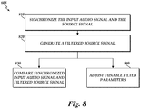
- FIG. 8 an illustrative flow diagram of an example of the steps undertaken in the block 608 for attenuating the audio noise according to an embodiment is shown.
- the input audio signal and the source signal are synchronized to compensate for time delays between the two signals.
- the signals can become out of sync for a variety of reasons, including the various delays resulting from taking different signal and computational paths.
- each signal can be stored in a data buffer (such as a circular buffer) of variable length so as to control the timing of each signal.
- a data buffer such as a circular buffer
- the input audio signal and the identified source signal may be received at the first synchronization block 402(1).
- the synchronization block 402(1) can store the signals in corresponding circular buffers data structures stored in the buffer block 416(1), where the lengths of the circular buffers can be a function of the desired delay for synchronizing the signals. In some embodiments the desired delay is calculated or estimated, for example, during a calibration mode.
- additional delays in the audio signal can occur at each of the n audio cancellers 404(1)-404( n ).
- filtering by n adaptive filters 412(1)-412( n ) the can introduce delays.
- the n identified source signals can experience various delays due to, for example, the time that it takes to identify and ultimately receive the identified source signals. Accordingly, the n synchronization blocks 402(1)-402( n ) can be used to compensate for those various delays and maintain the audio signal and the identified source signals synchronized during audio-cancelling processing.
- the method 608 continues to block 820 to filter the identified source signal to account for the acoustical effects impacting the audio noise, such as acoustical dynamics, speaker and microphone dynamics, and the like. Filtering is done because the identified source signal may not accurately represent the audio noise that is captured by the microphone 206. If the identified source signal substantially varies from the audio noise, audio suppression may not effective. To improve noise suppression, the effects of such factors can be estimated online in order to shape the identified source signal to closely match or replicate the audio noise. For example, referring now to Figure 4 , the synchronized audio input signal and the synchronized identified source signal 1 are passed to the audio noise canceller 404(1) and to adaptive filter 412(1).
- the adaptive filter 412(1) can then filter or shape the identified source signal 1 to produce a reference signal to approximately replicate the audio noise.
- the adaptive filter 412(1) can have one or more filter parameters (for example, one or more filter coefficient of a finite impulse response of infinite impulse response filter) that influences how the filter shapes the identified source signal.
- Some embodiments include tunable parameters to account for a wide range of acoustical effects.
- the method 608 can proceed to block 830 to generate a processed audio signal by comparing the synchronized audio input and the filtered source signal.
- the filtered source signal is subtracted from the synchronized audio input signal.
- Figure 4 shows that the output of the adaptive filter 412(1) is subtracted from the audio input signal to generate the audio signal with suppressed noise 1.
- the audio signal with suppressed noise 1 can be processed for communication or voice recognition applications. In another embodiment, the audio signal with suppressed noise 1 can be processed for further noise suppression.
- Figure 4 shows that the processed audio signal with suppressed noise 1 can be provided to synchronization blocks 402(2)-402( n ) and audio cancellers 404(2)-404( n ) to suppress additional noises 2- n with identified source signals 2- n .
- the method 608 can proceed to block 840 after performing block 820 to adjust the tunable filter parameters of the adaptive filter 412(1) to improve noise suppression with respect to a wide range of acoustical effects.
- the adjustment of the tunable filter parameters is governed by an adaptive law or update law.
- the adaptive filter 414(1) receives both the synchronized audio input signal and the identified source signal.
- the adaptive filter 414(1) can generate the filtered source signal.
- An "error signal” or "repressor signal” can be generated by comparing the audio input signal and the filtered source signal.
- the error signal can indicate how closely the adaptive filter is replicating the audio noise.
- the difference between the synchronized audio input signal and filtered source signal indicates the amount of mismatch between the filtered identified source signal and the audio noise. That is, a small error indicates that the adaptive filter is closely modeling the actual acoustic dynamics in the room.
- the adaptive law can be chosen (for example, based on a gradient or recursive least mean squares, or the like methods) to adjust the tunable filter parameters of the adaptive filter 412(1) in a manner that reduces the error signal.
- the adaptive filter 414(1) may not adjust its tunable parameters properly.
- the audio signal could contain the user's voice commands or audio noise from a second source.
- the error signal may not provide a meaningful indication of how closely the adaptive filter is matching, for example, the room acoustics with respect to audio noise 1.
- the DTD 414(1) block may turn off adjustment of the adaptive filter when the DTD block detects such a condition, as previously stated in connection with Figure 4 .
- the steps of synchronization and filtering can be performed using n identified source signals to cancel n audio noises.
- the audio noises are cancelled sequentially.
- the noises can be canceled in parallel.
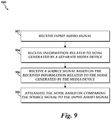
- Figure 9 is a flow diagram of a particular illustrative method 900 of audio noise suppression according to an embodiment.
- the method 900 includes receiving the input audio signal. Block 902 can be performed as described in connection with Figure 6 .
- the method 900 proceeds to block 904 for receiving information related to the noise generated by a separate media device.
- the audio processing device 202 can communicate with the separate media device by executing instructions from the audio signal analyzer module 216 and the communication module 220, as discussed in connection with Figure 2 .
- the separate media device may provide the audio processing device 202 an indication of whether or not the separate media device is generating noise having media content.
- the separate media device can communicate content-identification information, which the audio processing device 202 may use to search for a content source.
- content-identification information includes the TV channel, radio frequency, and like media broadcast selection information.
- the separate media device may send a source signal to the audio processing device 202.
- the method 900 proceeds to block 906 for receiving a source signal based on the received information related to the noise generated by the separate media device. For example, if the audio processing device receives an indication from the separated media device that the media device is generating noise, or if the audio processing device 202 receives content-identification information, then the audio processing device 202 can receive a source signal by performing the methods 604 and 606 of Figures 6 , 7A, and 7B as described above. In some embodiments, the audio processing device 202 receives the source signal from the separate media device. For example, the separate media device can transmit a copy of the media that the separate media device is playing.
- the method 900 can proceed to block 908 for attenuating the noise based on comparing the source signal to the input audio signal.
- the audio processing device 202 attenuate the audio noise by performing the method 608 of Figures 6 and 8 as described above.
- the technology is operational with numerous other general purpose or special purpose computing system environments or configurations.
- Examples of well-known computing systems, environments, and/or configurations that may be suitable for use with the invention include, but are not limited to, personal computers, server computers, hand-held or laptop devices, multiprocessor systems, processor-based systems, programmable consumer electronics, network PCs, minicomputers, mainframe computers, distributed computing environments that include any of the above systems or devices, and the like.
- instructions refer to computer-implemented steps for processing information in the system. Instructions can be implemented in software, firmware or hardware and include any type of programmed step undertaken by components of the system.
- a processor may be any conventional general purpose single- or multi-chip processor such as the AMD® Athlon® II or Phenom® II processor, Intel® i3®/i5®/i7® processors, Intel Xeon® processor, or any implementation of an ARM® processor.
- the processor may be any conventional special purpose processor, including OMAP processors, Qualcomm® processors such as Qualcomm®, or a digital signal processor or a graphics processor.
- the processor typically has conventional address lines, conventional data lines, and one or more conventional control lines.
- each of the modules comprises various sub-routines, procedures, definitional statements and macros.
- Each of the modules are typically separately compiled and linked into a single executable program. Therefore, the description of each of the modules is used for convenience to describe the functionality of the preferred system.
- the processes that are undergone by each of the modules may be arbitrarily redistributed to one of the other modules, combined together in a single module, or made available in, for example, a shareable dynamic link library.
- the system may be written in any conventional programming language such as C#, C, C++, BASIC, Pascal, or Java, and run under a conventional operating system.
- C#, C, C++, BASIC, Pascal, Java, and FORTRAN are industry standard programming languages for which many commercial compilers can be used to create executable code.
- the system may also be written using interpreted languages such as Perl, Python or Ruby.
- DSP digital signal processor
- ASIC application specific integrated circuit
- FPGA field programmable gate array
- a general purpose processor may be a microprocessor, but in the alternative, the processor may be any conventional processor, controller, microcontroller, or state machine.
- a processor may also be implemented as a combination of computing devices, e.g., a combination of a DSP and a microprocessor, a plurality of microprocessors, one or more microprocessors in conjunction with a DSP core, or any other such configuration.
- the functions and methods described may be implemented in hardware, software, or firmware executed on a processor, or any combination thereof. If implemented in software, the functions may be stored on or transmitted over as one or more instructions or code on a computer-readable medium.
- Computer-readable media include both computer storage media and communication media including any medium that facilitates transfer of a computer program from one place to another.
- a storage medium may be any available media that can be accessed by a computer.
- such computer-readable media can comprise RAM, ROM, EEPROM, CD-ROM or other optical disk storage, magnetic disk storage or other magnetic storage devices, or any other medium that can be used to carry or store desired program code in the form of instructions or data structures and that can be accessed by a computer.
- any connection is properly termed a computer-readable medium.
- the software is transmitted from a website, server, or other remote source using a coaxial cable, fiber optic cable, twisted pair, digital subscriber line (DSL), or wireless technologies such as infrared, radio, and microwave
- the coaxial cable, fiber optic cable, twisted pair, DSL, or wireless technologies such as infrared, radio, and microwave are included in the definition of medium.
- Disk and disc includes compact disc (CD), laser disc, optical disc, digital versatile disc (DVD), floppy disk and Blu-ray disc where disks usually reproduce data magnetically, while discs reproduce data optically with lasers. Combinations of the above should also be included within the scope of computer-readable media.
Landscapes
- Engineering & Computer Science (AREA)
- Signal Processing (AREA)
- Physics & Mathematics (AREA)
- Acoustics & Sound (AREA)
- Multimedia (AREA)
- Computational Linguistics (AREA)
- Quality & Reliability (AREA)
- Health & Medical Sciences (AREA)
- Audiology, Speech & Language Pathology (AREA)
- Human Computer Interaction (AREA)
- Soundproofing, Sound Blocking, And Sound Damping (AREA)
- Circuit For Audible Band Transducer (AREA)
Applications Claiming Priority (2)
| Application Number | Priority Date | Filing Date | Title |
|---|---|---|---|
| US13/787,605 US9275625B2 (en) | 2013-03-06 | 2013-03-06 | Content based noise suppression |
| PCT/US2014/017381 WO2014137612A1 (en) | 2013-03-06 | 2014-02-20 | Content based noise suppression |
Publications (2)
| Publication Number | Publication Date |
|---|---|
| EP2965496A1 EP2965496A1 (en) | 2016-01-13 |
| EP2965496B1 true EP2965496B1 (en) | 2018-01-03 |
Family
ID=50236325
Family Applications (1)
| Application Number | Title | Priority Date | Filing Date |
|---|---|---|---|
| EP14708428.9A Not-in-force EP2965496B1 (en) | 2013-03-06 | 2014-02-20 | Content based noise suppression |
Country Status (6)
| Country | Link |
|---|---|
| US (1) | US9275625B2 (zh) |
| EP (1) | EP2965496B1 (zh) |
| JP (1) | JP2016513816A (zh) |
| KR (1) | KR20150123902A (zh) |
| CN (1) | CN105027541B (zh) |
| WO (1) | WO2014137612A1 (zh) |
Cited By (1)
| Publication number | Priority date | Publication date | Assignee | Title |
|---|---|---|---|---|
| EP3786950B1 (en) * | 2019-08-30 | 2023-05-10 | Spotify AB | Systems and methods for generating a cleaned version of ambient sound |
Families Citing this family (33)
| Publication number | Priority date | Publication date | Assignee | Title |
|---|---|---|---|---|
| US9947333B1 (en) * | 2012-02-10 | 2018-04-17 | Amazon Technologies, Inc. | Voice interaction architecture with intelligent background noise cancellation |
| US9570087B2 (en) * | 2013-03-15 | 2017-02-14 | Broadcom Corporation | Single channel suppression of interfering sources |
| US9832299B2 (en) * | 2013-07-17 | 2017-11-28 | Empire Technology Development Llc | Background noise reduction in voice communication |
| US10149047B2 (en) * | 2014-06-18 | 2018-12-04 | Cirrus Logic Inc. | Multi-aural MMSE analysis techniques for clarifying audio signals |
| US10325591B1 (en) * | 2014-09-05 | 2019-06-18 | Amazon Technologies, Inc. | Identifying and suppressing interfering audio content |
| US9952095B1 (en) | 2014-09-29 | 2018-04-24 | Apple Inc. | Methods and systems for modulation and demodulation of optical signals |
| US9979955B1 (en) * | 2014-09-30 | 2018-05-22 | Apple Inc. | Calibration methods for near-field acoustic imaging systems |
| US9747488B2 (en) | 2014-09-30 | 2017-08-29 | Apple Inc. | Active sensing element for acoustic imaging systems |
| JP6322125B2 (ja) * | 2014-11-28 | 2018-05-09 | 日本電信電話株式会社 | 音声認識装置、音声認識方法および音声認識プログラム |
| CN105988049B (zh) * | 2015-02-28 | 2019-02-19 | 惠州市德赛西威汽车电子股份有限公司 | 一种噪声抑制的调试方法 |
| US9672821B2 (en) * | 2015-06-05 | 2017-06-06 | Apple Inc. | Robust speech recognition in the presence of echo and noise using multiple signals for discrimination |
| EP3317878B1 (de) * | 2015-06-30 | 2020-03-25 | Fraunhofer Gesellschaft zur Förderung der Angewand | Verfahren und vorrichtung zum erzeugen einer datenbank |
| US11048902B2 (en) | 2015-08-20 | 2021-06-29 | Appple Inc. | Acoustic imaging system architecture |
| CN105489215B (zh) * | 2015-11-18 | 2019-03-12 | 珠海格力电器股份有限公司 | 一种噪声源识别方法及系统 |
| US11277210B2 (en) * | 2015-11-19 | 2022-03-15 | The Hong Kong University Of Science And Technology | Method, system and storage medium for signal separation |
| DE112017001830B4 (de) * | 2016-05-06 | 2024-02-22 | Robert Bosch Gmbh | Sprachverbesserung und audioereignisdetektion für eine umgebung mit nichtstationären geräuschen |
| US9838815B1 (en) * | 2016-06-01 | 2017-12-05 | Qualcomm Incorporated | Suppressing or reducing effects of wind turbulence |
| KR102515996B1 (ko) * | 2016-08-26 | 2023-03-31 | 삼성전자주식회사 | 음성 인식을 위한 전자 장치 및 그 제어 방법 |
| US10554822B1 (en) * | 2017-02-28 | 2020-02-04 | SoliCall Ltd. | Noise removal in call centers |
| JP6545419B2 (ja) * | 2017-03-08 | 2019-07-17 | 三菱電機株式会社 | 音響信号処理装置、音響信号処理方法、及びハンズフリー通話装置 |
| JP7020799B2 (ja) * | 2017-05-16 | 2022-02-16 | ソニーグループ株式会社 | 情報処理装置、及び情報処理方法 |
| US10475449B2 (en) * | 2017-08-07 | 2019-11-12 | Sonos, Inc. | Wake-word detection suppression |
| US10313218B2 (en) * | 2017-08-11 | 2019-06-04 | 2236008 Ontario Inc. | Measuring and compensating for jitter on systems running latency-sensitive audio signal processing |
| EP3692530B1 (en) | 2017-10-02 | 2021-09-08 | Dolby Laboratories Licensing Corporation | Audio de-esser independent of absolute signal level |
| US10847178B2 (en) * | 2018-05-18 | 2020-11-24 | Sonos, Inc. | Linear filtering for noise-suppressed speech detection |
| US10297266B1 (en) | 2018-06-15 | 2019-05-21 | Cisco Technology, Inc. | Adaptive noise cancellation for multiple audio endpoints in a shared space |
| US10867615B2 (en) * | 2019-01-25 | 2020-12-15 | Comcast Cable Communications, Llc | Voice recognition with timing information for noise cancellation |
| EP3709194A1 (en) | 2019-03-15 | 2020-09-16 | Spotify AB | Ensemble-based data comparison |
| CN110047497B (zh) * | 2019-05-14 | 2021-06-11 | 腾讯科技(深圳)有限公司 | 背景音频信号滤除方法、装置及存储介质 |
| US11017792B2 (en) * | 2019-06-17 | 2021-05-25 | Bose Corporation | Modular echo cancellation unit |
| US11328722B2 (en) | 2020-02-11 | 2022-05-10 | Spotify Ab | Systems and methods for generating a singular voice audio stream |
| US11308959B2 (en) | 2020-02-11 | 2022-04-19 | Spotify Ab | Dynamic adjustment of wake word acceptance tolerance thresholds in voice-controlled devices |
| US11950512B2 (en) | 2020-03-23 | 2024-04-02 | Apple Inc. | Thin-film acoustic imaging system for imaging through an exterior surface of an electronic device housing |
Family Cites Families (14)
| Publication number | Priority date | Publication date | Assignee | Title |
|---|---|---|---|---|
| US7747002B1 (en) * | 2000-03-15 | 2010-06-29 | Broadcom Corporation | Method and system for stereo echo cancellation for VoIP communication systems |
| CN100538701C (zh) * | 2000-07-31 | 2009-09-09 | 兰德马克数字服务公司 | 用于从媒体样本辨认媒体实体的方法 |
| US6990453B2 (en) * | 2000-07-31 | 2006-01-24 | Landmark Digital Services Llc | System and methods for recognizing sound and music signals in high noise and distortion |
| EP1457889A1 (en) * | 2003-03-13 | 2004-09-15 | Koninklijke Philips Electronics N.V. | Improved fingerprint matching method and system |
| JP2005077865A (ja) * | 2003-09-02 | 2005-03-24 | Sony Corp | 音楽検索システムおよび方法、情報処理装置および方法、プログラム、並びに記録媒体 |
| CN1897054A (zh) | 2005-07-14 | 2007-01-17 | 松下电器产业株式会社 | 可根据声音种类发出警报的传输装置及方法 |
| US20090012786A1 (en) | 2007-07-06 | 2009-01-08 | Texas Instruments Incorporated | Adaptive Noise Cancellation |
| JP4431836B2 (ja) * | 2007-07-26 | 2010-03-17 | 株式会社カシオ日立モバイルコミュニケーションズ | 音声取得装置、雑音除去システム、及び、プログラム |
| US20090034750A1 (en) | 2007-07-31 | 2009-02-05 | Motorola, Inc. | System and method to evaluate an audio configuration |
| US9112989B2 (en) | 2010-04-08 | 2015-08-18 | Qualcomm Incorporated | System and method of smart audio logging for mobile devices |
| US9280598B2 (en) | 2010-05-04 | 2016-03-08 | Soundhound, Inc. | Systems and methods for sound recognition |
| US8812014B2 (en) | 2010-08-30 | 2014-08-19 | Qualcomm Incorporated | Audio-based environment awareness |
| JP5561195B2 (ja) * | 2011-02-07 | 2014-07-30 | 株式会社Jvcケンウッド | ノイズ除去装置およびノイズ除去方法 |
| US9384726B2 (en) | 2012-01-06 | 2016-07-05 | Texas Instruments Incorporated | Feedback microphones encoder modulators, signal generators, mixers, amplifiers, summing nodes |
-
2013
- 2013-03-06 US US13/787,605 patent/US9275625B2/en active Active
-
2014
- 2014-02-20 CN CN201480010777.4A patent/CN105027541B/zh active Active
- 2014-02-20 EP EP14708428.9A patent/EP2965496B1/en not_active Not-in-force
- 2014-02-20 JP JP2015561382A patent/JP2016513816A/ja active Pending
- 2014-02-20 WO PCT/US2014/017381 patent/WO2014137612A1/en active Application Filing
- 2014-02-20 KR KR1020157026895A patent/KR20150123902A/ko active IP Right Grant
Cited By (2)
| Publication number | Priority date | Publication date | Assignee | Title |
|---|---|---|---|---|
| EP3786950B1 (en) * | 2019-08-30 | 2023-05-10 | Spotify AB | Systems and methods for generating a cleaned version of ambient sound |
| EP4191585A1 (en) * | 2019-08-30 | 2023-06-07 | Spotify AB | Systems and methods for generating a cleaned version of ambient sound |
Also Published As
| Publication number | Publication date |
|---|---|
| KR20150123902A (ko) | 2015-11-04 |
| WO2014137612A1 (en) | 2014-09-12 |
| CN105027541B (zh) | 2018-01-16 |
| CN105027541A (zh) | 2015-11-04 |
| US20140254816A1 (en) | 2014-09-11 |
| US9275625B2 (en) | 2016-03-01 |
| JP2016513816A (ja) | 2016-05-16 |
| EP2965496A1 (en) | 2016-01-13 |
Similar Documents
| Publication | Publication Date | Title |
|---|---|---|
| EP2965496B1 (en) | Content based noise suppression | |
| US9704478B1 (en) | Audio output masking for improved automatic speech recognition | |
| RU2467406C2 (ru) | Способ и устройство для поддержки воспринимаемости речи в многоканальном звуковом сопровождении с минимальным влиянием на систему объемного звучания | |
| US20230074658A1 (en) | Linear filtering for noise-suppressed speech detection via multiple network microphone devices | |
| US9558755B1 (en) | Noise suppression assisted automatic speech recognition | |
| KR20180056752A (ko) | 초광대역 음악을 위한 적응적 잡음 억제 | |
| US9286883B1 (en) | Acoustic echo cancellation and automatic speech recognition with random noise | |
| US10325591B1 (en) | Identifying and suppressing interfering audio content | |
| JP2011516901A (ja) | 受信機を使用するコンテキスト抑圧のためのシステム、方法、および装置 | |
| BRPI0812029B1 (pt) | método de recuperar dados ocultados, dispositivo de telecomunicações, aparelho de ocultar dados, método de ocultar dados e caixa de conjunto superior | |
| US9773510B1 (en) | Correcting clock drift via embedded sine waves | |
| Park et al. | Acoustic interference cancellation for a voice-driven interface in smart TVs | |
| US10937418B1 (en) | Echo cancellation by acoustic playback estimation | |
| US8582754B2 (en) | Method and system for echo cancellation in presence of streamed audio | |
| CN105869656B (zh) | 一种语音信号清晰度的确定方法及装置 | |
| KR20150032562A (ko) | 소음을 제거하기 위한 방법, 장치 및 모바일 단말 | |
| WO2017045512A1 (zh) | 一种语音识别的方法、装置、终端及语音识别设备 | |
| CN115804105A (zh) | 用于声学透明度的系统、装置和方法 | |
| WO2018219459A1 (en) | A method and an apparatus for enhancing an audio signal captured in an indoor environment | |
| GB2575873A (en) | Processing audio signals | |
| GB2516208B (en) | Noise reduction in voice communications | |
| Eskimez et al. | Real-time joint personalized speech enhancement and acoustic echo cancellation with e3net | |
| KR100754558B1 (ko) | 주기 신호 향상 시스템 | |
| US11508379B2 (en) | Asynchronous ad-hoc distributed microphone array processing in smart home applications using voice biometrics | |
| Kim et al. | Robust audio fingerprinting method using prominent peak pair based on modulated complex lapped transform |
Legal Events
| Date | Code | Title | Description |
|---|---|---|---|
| PUAI | Public reference made under article 153(3) epc to a published international application that has entered the european phase |
Free format text: ORIGINAL CODE: 0009012 |
|
| 17P | Request for examination filed |
Effective date: 20150811 |
|
| AK | Designated contracting states |
Kind code of ref document: A1 Designated state(s): AL AT BE BG CH CY CZ DE DK EE ES FI FR GB GR HR HU IE IS IT LI LT LU LV MC MK MT NL NO PL PT RO RS SE SI SK SM TR |
|
| AX | Request for extension of the european patent |
Extension state: BA ME |
|
| RIN1 | Information on inventor provided before grant (corrected) |
Inventor name: KIM, LAE-HOON Inventor name: SHIN, JONGWON Inventor name: MOHAMMAD, ASIF IQBAL Inventor name: VISSER, ERIK |
|
| DAX | Request for extension of the european patent (deleted) | ||
| 17Q | First examination report despatched |
Effective date: 20170118 |
|
| GRAP | Despatch of communication of intention to grant a patent |
Free format text: ORIGINAL CODE: EPIDOSNIGR1 |
|
| INTG | Intention to grant announced |
Effective date: 20170711 |
|
| RAP1 | Party data changed (applicant data changed or rights of an application transferred) |
Owner name: QUALCOMM INCORPORATED |
|
| GRAS | Grant fee paid |
Free format text: ORIGINAL CODE: EPIDOSNIGR3 |
|
| GRAA | (expected) grant |
Free format text: ORIGINAL CODE: 0009210 |
|
| AK | Designated contracting states |
Kind code of ref document: B1 Designated state(s): AL AT BE BG CH CY CZ DE DK EE ES FI FR GB GR HR HU IE IS IT LI LT LU LV MC MK MT NL NO PL PT RO RS SE SI SK SM TR |
|
| REG | Reference to a national code |
Ref country code: GB Ref legal event code: FG4D |
|
| REG | Reference to a national code |
Ref country code: CH Ref legal event code: EP Ref country code: AT Ref legal event code: REF Ref document number: 961250 Country of ref document: AT Kind code of ref document: T Effective date: 20180115 |
|
| REG | Reference to a national code |
Ref country code: IE Ref legal event code: FG4D |
|
| REG | Reference to a national code |
Ref country code: DE Ref legal event code: R096 Ref document number: 602014019358 Country of ref document: DE |
|
| REG | Reference to a national code |
Ref country code: FR Ref legal event code: PLFP Year of fee payment: 5 |
|
| REG | Reference to a national code |
Ref country code: NL Ref legal event code: MP Effective date: 20180103 |
|
| REG | Reference to a national code |
Ref country code: LT Ref legal event code: MG4D |
|
| PGFP | Annual fee paid to national office [announced via postgrant information from national office to epo] |
Ref country code: FR Payment date: 20180226 Year of fee payment: 5 |
|
| REG | Reference to a national code |
Ref country code: AT Ref legal event code: MK05 Ref document number: 961250 Country of ref document: AT Kind code of ref document: T Effective date: 20180103 |
|
| PG25 | Lapsed in a contracting state [announced via postgrant information from national office to epo] |
Ref country code: NL Free format text: LAPSE BECAUSE OF FAILURE TO SUBMIT A TRANSLATION OF THE DESCRIPTION OR TO PAY THE FEE WITHIN THE PRESCRIBED TIME-LIMIT Effective date: 20180103 |
|
| PG25 | Lapsed in a contracting state [announced via postgrant information from national office to epo] |
Ref country code: ES Free format text: LAPSE BECAUSE OF FAILURE TO SUBMIT A TRANSLATION OF THE DESCRIPTION OR TO PAY THE FEE WITHIN THE PRESCRIBED TIME-LIMIT Effective date: 20180103 Ref country code: CY Free format text: LAPSE BECAUSE OF FAILURE TO SUBMIT A TRANSLATION OF THE DESCRIPTION OR TO PAY THE FEE WITHIN THE PRESCRIBED TIME-LIMIT Effective date: 20180103 Ref country code: NO Free format text: LAPSE BECAUSE OF FAILURE TO SUBMIT A TRANSLATION OF THE DESCRIPTION OR TO PAY THE FEE WITHIN THE PRESCRIBED TIME-LIMIT Effective date: 20180403 Ref country code: FI Free format text: LAPSE BECAUSE OF FAILURE TO SUBMIT A TRANSLATION OF THE DESCRIPTION OR TO PAY THE FEE WITHIN THE PRESCRIBED TIME-LIMIT Effective date: 20180103 Ref country code: LT Free format text: LAPSE BECAUSE OF FAILURE TO SUBMIT A TRANSLATION OF THE DESCRIPTION OR TO PAY THE FEE WITHIN THE PRESCRIBED TIME-LIMIT Effective date: 20180103 Ref country code: HR Free format text: LAPSE BECAUSE OF FAILURE TO SUBMIT A TRANSLATION OF THE DESCRIPTION OR TO PAY THE FEE WITHIN THE PRESCRIBED TIME-LIMIT Effective date: 20180103 |
|
| PG25 | Lapsed in a contracting state [announced via postgrant information from national office to epo] |
Ref country code: BG Free format text: LAPSE BECAUSE OF FAILURE TO SUBMIT A TRANSLATION OF THE DESCRIPTION OR TO PAY THE FEE WITHIN THE PRESCRIBED TIME-LIMIT Effective date: 20180403 Ref country code: RS Free format text: LAPSE BECAUSE OF FAILURE TO SUBMIT A TRANSLATION OF THE DESCRIPTION OR TO PAY THE FEE WITHIN THE PRESCRIBED TIME-LIMIT Effective date: 20180103 Ref country code: AT Free format text: LAPSE BECAUSE OF FAILURE TO SUBMIT A TRANSLATION OF THE DESCRIPTION OR TO PAY THE FEE WITHIN THE PRESCRIBED TIME-LIMIT Effective date: 20180103 Ref country code: SE Free format text: LAPSE BECAUSE OF FAILURE TO SUBMIT A TRANSLATION OF THE DESCRIPTION OR TO PAY THE FEE WITHIN THE PRESCRIBED TIME-LIMIT Effective date: 20180103 Ref country code: LV Free format text: LAPSE BECAUSE OF FAILURE TO SUBMIT A TRANSLATION OF THE DESCRIPTION OR TO PAY THE FEE WITHIN THE PRESCRIBED TIME-LIMIT Effective date: 20180103 Ref country code: IS Free format text: LAPSE BECAUSE OF FAILURE TO SUBMIT A TRANSLATION OF THE DESCRIPTION OR TO PAY THE FEE WITHIN THE PRESCRIBED TIME-LIMIT Effective date: 20180503 Ref country code: GR Free format text: LAPSE BECAUSE OF FAILURE TO SUBMIT A TRANSLATION OF THE DESCRIPTION OR TO PAY THE FEE WITHIN THE PRESCRIBED TIME-LIMIT Effective date: 20180404 Ref country code: PL Free format text: LAPSE BECAUSE OF FAILURE TO SUBMIT A TRANSLATION OF THE DESCRIPTION OR TO PAY THE FEE WITHIN THE PRESCRIBED TIME-LIMIT Effective date: 20180103 |
|
| REG | Reference to a national code |
Ref country code: CH Ref legal event code: PL |
|
| REG | Reference to a national code |
Ref country code: DE Ref legal event code: R097 Ref document number: 602014019358 Country of ref document: DE |
|
| PG25 | Lapsed in a contracting state [announced via postgrant information from national office to epo] |
Ref country code: IT Free format text: LAPSE BECAUSE OF FAILURE TO SUBMIT A TRANSLATION OF THE DESCRIPTION OR TO PAY THE FEE WITHIN THE PRESCRIBED TIME-LIMIT Effective date: 20180103 Ref country code: RO Free format text: LAPSE BECAUSE OF FAILURE TO SUBMIT A TRANSLATION OF THE DESCRIPTION OR TO PAY THE FEE WITHIN THE PRESCRIBED TIME-LIMIT Effective date: 20180103 Ref country code: EE Free format text: LAPSE BECAUSE OF FAILURE TO SUBMIT A TRANSLATION OF THE DESCRIPTION OR TO PAY THE FEE WITHIN THE PRESCRIBED TIME-LIMIT Effective date: 20180103 Ref country code: AL Free format text: LAPSE BECAUSE OF FAILURE TO SUBMIT A TRANSLATION OF THE DESCRIPTION OR TO PAY THE FEE WITHIN THE PRESCRIBED TIME-LIMIT Effective date: 20180103 Ref country code: MC Free format text: LAPSE BECAUSE OF FAILURE TO SUBMIT A TRANSLATION OF THE DESCRIPTION OR TO PAY THE FEE WITHIN THE PRESCRIBED TIME-LIMIT Effective date: 20180103 |
|
| PLBE | No opposition filed within time limit |
Free format text: ORIGINAL CODE: 0009261 |
|
| STAA | Information on the status of an ep patent application or granted ep patent |
Free format text: STATUS: NO OPPOSITION FILED WITHIN TIME LIMIT |
|
| REG | Reference to a national code |
Ref country code: IE Ref legal event code: MM4A |
|
| REG | Reference to a national code |
Ref country code: BE Ref legal event code: MM Effective date: 20180228 |
|
| PG25 | Lapsed in a contracting state [announced via postgrant information from national office to epo] |
Ref country code: DK Free format text: LAPSE BECAUSE OF FAILURE TO SUBMIT A TRANSLATION OF THE DESCRIPTION OR TO PAY THE FEE WITHIN THE PRESCRIBED TIME-LIMIT Effective date: 20180103 Ref country code: SM Free format text: LAPSE BECAUSE OF FAILURE TO SUBMIT A TRANSLATION OF THE DESCRIPTION OR TO PAY THE FEE WITHIN THE PRESCRIBED TIME-LIMIT Effective date: 20180103 Ref country code: CH Free format text: LAPSE BECAUSE OF NON-PAYMENT OF DUE FEES Effective date: 20180228 Ref country code: SK Free format text: LAPSE BECAUSE OF FAILURE TO SUBMIT A TRANSLATION OF THE DESCRIPTION OR TO PAY THE FEE WITHIN THE PRESCRIBED TIME-LIMIT Effective date: 20180103 Ref country code: LU Free format text: LAPSE BECAUSE OF NON-PAYMENT OF DUE FEES Effective date: 20180220 Ref country code: LI Free format text: LAPSE BECAUSE OF NON-PAYMENT OF DUE FEES Effective date: 20180228 Ref country code: CZ Free format text: LAPSE BECAUSE OF FAILURE TO SUBMIT A TRANSLATION OF THE DESCRIPTION OR TO PAY THE FEE WITHIN THE PRESCRIBED TIME-LIMIT Effective date: 20180103 |
|
| 26N | No opposition filed |
Effective date: 20181005 |
|
| PG25 | Lapsed in a contracting state [announced via postgrant information from national office to epo] |
Ref country code: IE Free format text: LAPSE BECAUSE OF NON-PAYMENT OF DUE FEES Effective date: 20180220 |
|
| PG25 | Lapsed in a contracting state [announced via postgrant information from national office to epo] |
Ref country code: SI Free format text: LAPSE BECAUSE OF FAILURE TO SUBMIT A TRANSLATION OF THE DESCRIPTION OR TO PAY THE FEE WITHIN THE PRESCRIBED TIME-LIMIT Effective date: 20180103 Ref country code: BE Free format text: LAPSE BECAUSE OF NON-PAYMENT OF DUE FEES Effective date: 20180228 |
|
| PG25 | Lapsed in a contracting state [announced via postgrant information from national office to epo] |
Ref country code: MT Free format text: LAPSE BECAUSE OF NON-PAYMENT OF DUE FEES Effective date: 20180220 |
|
| PG25 | Lapsed in a contracting state [announced via postgrant information from national office to epo] |
Ref country code: FR Free format text: LAPSE BECAUSE OF NON-PAYMENT OF DUE FEES Effective date: 20190228 |
|
| PG25 | Lapsed in a contracting state [announced via postgrant information from national office to epo] |
Ref country code: TR Free format text: LAPSE BECAUSE OF FAILURE TO SUBMIT A TRANSLATION OF THE DESCRIPTION OR TO PAY THE FEE WITHIN THE PRESCRIBED TIME-LIMIT Effective date: 20180103 |
|
| PGFP | Annual fee paid to national office [announced via postgrant information from national office to epo] |
Ref country code: DE Payment date: 20200115 Year of fee payment: 7 Ref country code: GB Payment date: 20200130 Year of fee payment: 7 |
|
| PG25 | Lapsed in a contracting state [announced via postgrant information from national office to epo] |
Ref country code: PT Free format text: LAPSE BECAUSE OF FAILURE TO SUBMIT A TRANSLATION OF THE DESCRIPTION OR TO PAY THE FEE WITHIN THE PRESCRIBED TIME-LIMIT Effective date: 20180103 |
|
| PG25 | Lapsed in a contracting state [announced via postgrant information from national office to epo] |
Ref country code: MK Free format text: LAPSE BECAUSE OF NON-PAYMENT OF DUE FEES Effective date: 20180103 Ref country code: HU Free format text: LAPSE BECAUSE OF FAILURE TO SUBMIT A TRANSLATION OF THE DESCRIPTION OR TO PAY THE FEE WITHIN THE PRESCRIBED TIME-LIMIT; INVALID AB INITIO Effective date: 20140220 |
|
| REG | Reference to a national code |
Ref country code: DE Ref legal event code: R119 Ref document number: 602014019358 Country of ref document: DE |
|
| GBPC | Gb: european patent ceased through non-payment of renewal fee |
Effective date: 20210220 |
|
| PG25 | Lapsed in a contracting state [announced via postgrant information from national office to epo] |
Ref country code: DE Free format text: LAPSE BECAUSE OF NON-PAYMENT OF DUE FEES Effective date: 20210901 Ref country code: GB Free format text: LAPSE BECAUSE OF NON-PAYMENT OF DUE FEES Effective date: 20210220 |