EP2964551B1 - Singulator - Google Patents
Singulator Download PDFInfo
- Publication number
- EP2964551B1 EP2964551B1 EP14716008.9A EP14716008A EP2964551B1 EP 2964551 B1 EP2964551 B1 EP 2964551B1 EP 14716008 A EP14716008 A EP 14716008A EP 2964551 B1 EP2964551 B1 EP 2964551B1
- Authority
- EP
- European Patent Office
- Prior art keywords
- zone
- articles
- module
- along
- station
- Prior art date
- Legal status (The legal status is an assumption and is not a legal conclusion. Google has not performed a legal analysis and makes no representation as to the accuracy of the status listed.)
- Active
Links
- 230000033001 locomotion Effects 0.000 claims description 81
- 230000000284 resting effect Effects 0.000 claims description 33
- 230000001174 ascending effect Effects 0.000 claims description 8
- 230000005540 biological transmission Effects 0.000 claims description 6
- 238000000034 method Methods 0.000 claims description 3
- 230000008569 process Effects 0.000 claims description 2
- 238000001514 detection method Methods 0.000 description 6
- 230000000694 effects Effects 0.000 description 5
- 230000006870 function Effects 0.000 description 4
- 230000003134 recirculating effect Effects 0.000 description 4
- 239000003638 chemical reducing agent Substances 0.000 description 3
- 238000000926 separation method Methods 0.000 description 3
- 230000006399 behavior Effects 0.000 description 2
- 238000010276 construction Methods 0.000 description 2
- 230000005484 gravity Effects 0.000 description 2
- 238000012545 processing Methods 0.000 description 2
- 238000012546 transfer Methods 0.000 description 2
- 235000009854 Cucurbita moschata Nutrition 0.000 description 1
- 240000001980 Cucurbita pepo Species 0.000 description 1
- 235000009852 Cucurbita pepo Nutrition 0.000 description 1
- 241000196324 Embryophyta Species 0.000 description 1
- 230000003213 activating effect Effects 0.000 description 1
- 230000004913 activation Effects 0.000 description 1
- 230000002547 anomalous effect Effects 0.000 description 1
- 230000001747 exhibiting effect Effects 0.000 description 1
- 229940090441 infed Drugs 0.000 description 1
- 238000012423 maintenance Methods 0.000 description 1
- 238000012544 monitoring process Methods 0.000 description 1
- 230000037361 pathway Effects 0.000 description 1
- 235000020354 squash Nutrition 0.000 description 1
- 238000013519 translation Methods 0.000 description 1
Images


Classifications
-
- B—PERFORMING OPERATIONS; TRANSPORTING
- B65—CONVEYING; PACKING; STORING; HANDLING THIN OR FILAMENTARY MATERIAL
- B65G—TRANSPORT OR STORAGE DEVICES, e.g. CONVEYORS FOR LOADING OR TIPPING, SHOP CONVEYOR SYSTEMS OR PNEUMATIC TUBE CONVEYORS
- B65G47/00—Article or material-handling devices associated with conveyors; Methods employing such devices
- B65G47/52—Devices for transferring articles or materials between conveyors i.e. discharging or feeding devices
- B65G47/68—Devices for transferring articles or materials between conveyors i.e. discharging or feeding devices adapted to receive articles arriving in one layer from one conveyor lane and to transfer them in individual layers to more than one conveyor lane or to one broader conveyor lane, or vice versa, e.g. combining the flows of articles conveyed by more than one conveyor
- B65G47/682—Devices for transferring articles or materials between conveyors i.e. discharging or feeding devices adapted to receive articles arriving in one layer from one conveyor lane and to transfer them in individual layers to more than one conveyor lane or to one broader conveyor lane, or vice versa, e.g. combining the flows of articles conveyed by more than one conveyor from a single conveyor lane consisting of one conveyor or several adjacent conveyors
-
- B—PERFORMING OPERATIONS; TRANSPORTING
- B65—CONVEYING; PACKING; STORING; HANDLING THIN OR FILAMENTARY MATERIAL
- B65G—TRANSPORT OR STORAGE DEVICES, e.g. CONVEYORS FOR LOADING OR TIPPING, SHOP CONVEYOR SYSTEMS OR PNEUMATIC TUBE CONVEYORS
- B65G47/00—Article or material-handling devices associated with conveyors; Methods employing such devices
- B65G47/22—Devices influencing the relative position or the attitude of articles during transit by conveyors
- B65G47/26—Devices influencing the relative position or the attitude of articles during transit by conveyors arranging the articles, e.g. varying spacing between individual articles
- B65G47/261—Accumulating articles
- B65G47/268—Accumulating articles by means of belt or chain conveyor
-
- B—PERFORMING OPERATIONS; TRANSPORTING
- B65—CONVEYING; PACKING; STORING; HANDLING THIN OR FILAMENTARY MATERIAL
- B65G—TRANSPORT OR STORAGE DEVICES, e.g. CONVEYORS FOR LOADING OR TIPPING, SHOP CONVEYOR SYSTEMS OR PNEUMATIC TUBE CONVEYORS
- B65G47/00—Article or material-handling devices associated with conveyors; Methods employing such devices
- B65G47/22—Devices influencing the relative position or the attitude of articles during transit by conveyors
- B65G47/26—Devices influencing the relative position or the attitude of articles during transit by conveyors arranging the articles, e.g. varying spacing between individual articles
- B65G47/30—Devices influencing the relative position or the attitude of articles during transit by conveyors arranging the articles, e.g. varying spacing between individual articles during transit by a series of conveyors
Definitions
- the present invention relates to a singulator, intended in particular to receive a plurality of incoming loose articles and to output the aforementioned plurality of articles, suitably singulated (in one or more lines), i.e. arranged consecutively along predetermined advancement lines.
- WO 2012/101576 A2 discloses singulators.
- the areas of use of singulators are varied, and include, by way of non-limiting example, the field of sorting and delivering mail, the dispatching and parcel distribution sector, etc.
- a first type of these machines comprises, in the main structure thereof intended for singulating operations, the use of a first converger station consisting of a central high-friction conveyor belt flanked on both sides by two respective roller conveyors having axes that are inclined relative to the direction of advancement of the articles.
- roller conveyors impart, to the articles resting thereon, an advancement motion and lateral translation towards the high-friction central belt, carrying the majority of articles onto the central belt itself.
- a diverger station Located after the converger station there is a diverger station, which is also a high-friction central belt which follows on from the central belt of the converger station and is designed to receive the articles that have been brought to the central zone of the device.
- an article that might be at least partially resting on the central belt would be conveyed thereby and would not be affected by the lateral thrust of the corresponding roller conveyor; in contrast, a product resting exclusively on the roller conveyor will be conveyed away from the central belt.
- Appropriate conveyor belts or recirculating belts are present at the sides of the diverger station, which belts are destined to receive the products that have been conveyed away from the diverger roller conveyors and return them to the inlet of the machine and in particular to the inlet of the converger station so that they can be newly processed.
- the products are singulated at the central zone of the machine, while all the articles which, in particular due to being superimposed in a direction that is transversal to the conveyance direction, should they not reach the central zone, are advantageously recirculated via the diverger station, and via the recirculating belts they are returned to the machine inlet and then re-processed.
- U.S. patent 5701989 describes, with particular reference to figure 13 , a singulator according to the preamble of claim 1.
- the main difference is linked to the absence of a conveyor belt in the convergence zone (in other words there are only two roller conveyors converging towards the central advancement axis) and to the presence of a diverger station consisting of a plurality of additional conveyor belts with the aim of removing articles that are not singulated in such a way as to return them into the singulating cycle.
- a second type of known devices suitable for singulating products is constituted by a complex apparatus in which all articles entering the device are suitably scanned by, for example, suitable cameras which can provide the read information to a control unit that reconstructs the distribution of the articles along the advancement pathway thereof.
- a movement surface is present, consisting of an array of individual conveyor belts, all independently movable.
- the movement surface consists of a fixed number of rows and columns defined by a plurality of individual conveyor belts which are driven by the control unit via respective motors.
- the control unit drives the conveyor belts at differentiated speeds, so as to be able to suitably orientate the articles by rotating them, and also to be able to space them apart in the longitudinal direction by differentiating the advancement speeds of the belts on which the articles are resting.
- the various articles When leaving the deck, the various articles will be orientated in an orderly manner and will be sufficiently spaced along their respective advancement lines.
- the singulators described above are not able to assure the correct singulation of articles in the event that two or more of said articles are superimposed on one another.
- the singulator having the converger station, the diverger station and the recirculating belt the latter is extremely large, both longitudinally and transversally.
- the operating principle requires that all the products be carried on the central singulating conveyor belt, and implies the need to have predetermined lengths in the conveyance direction so as to ensure adequate filling of the high-friction central belt.
- the device has a multiplicity of conveyor belts that are independently movable, it is much more compact, but at the same time, extremely complex in terms of the construction and management of the operation thereof.
- each of the conveyor belts is equipped with a respective drive and a respective motor, which clearly increase the costs of construction and maintenance, while at the same time reducing the reliability of the singulator (considering the high number of electrical and mechanical parts that make it up) .
- the object of the present invention is thus to substantially resolve at least one of the drawbacks and/or limitations of the previous solutions.
- a first aim of the singulator is to provide a machine that is capable of assuring an effective singulation of articles, and in particular of assuring, in a diverger module, the separation of articles also in the event that at least two of them are vertically superimposed on one another.
- a further aim of the singulator is to provide a machine that is sufficiently compact and at the same time fairly simple from the point of view of management and control.
- One objective is to limit the active control functions required for singulating, thus also limiting the number of motors (and the consequent electronics), as well as the mechanical parts in motion.
- a further aim is to contain not only the transversal dimensions of the device, but also the longitudinal dimensions, by providing a singulator able to guarantee good singulating performances in terms of a maximum number of articles that can be singulated per unit of time and in terms of reliability of singulation.
- 1 denotes in its entirety a singulator as described below.
- the singulator that is the subject matter of the following description is particularly intended for the singulation of loosely arranged items 5.
- the articles 5, which may have undergone further manipulation if necessary before reaching the inlet of the singulator e.g. unstacking operations for supplying them to the inlet in a two-dimensional configuration
- a suitable conveyor belt or equivalent system for infeeding them to the main modules of the singulator.
- the products initially reach an inlet station 3 of a converger module 2.
- the converger module 2 extends longitudinally along a main direction 6 of advancement of the articles between the above-mentioned inlet station 3 and an outlet station 4.
- the loose articles 5 entering the converger module 2 will be conveyed (and appropriately handled) starting from the inlet station 3 along the main advancement direction up until reaching the outlet station 4, so as to be received by successive modules of the singulator.
- the converger module 2 primarily features at least a first zone 7 defined between the inlet station 3 and the outlet station 4 along the main advancement or conveyance direction of the articles 6.
- This zone 7 will generally, in a view from above, have a rectangular profile with a main geometry that extends substantially parallel to the main direction of extension 6, and with the two opposite shorter sides located at the inlet and outlet stations 3 and 4.
- This zone 7 will be generally configured so as to impart to the articles resting thereon a direct advancement motion exclusively along the main advancement direction 6 (see for example figure 1 ).
- the first zone 7 will include at least one conveyor configured so as to impart this movement to the articles 5.
- the first zone 7 i.e. the corresponding conveyor
- the first zone 7 may be configured so as to impart to the articles 5 resting thereon not only an advancement motion along the main direction 6, but also a lateral movement 9b in a direction perpendicular to the advancement direction directed towards a second zone 8.
- the conveyor will be able to impart a parallel motion to the articles or, in an alternative embodiment, a motion directionally inclined (resultant R in the figures) relative to the main advancement direction 6 (or to the main axis of extension of the singulator).
- the converger module 2 also features a second zone 8 which flanks the first zone 7 along the main advancement direction 6 and also extends between the inlet station 3 and the outlet station 4 of the module 2.
- the second zone 8 is configured to impart to the articles 5 resting thereon an advancement motion along the main direction 6 and also a lateral movement 9a in the direction of the first zone 7.
- the second zone 8 will include at least one conveyor (and in general a plurality thereof) configured to impart the described movement to the articles (inclined; resultant R).
- This second zone 8 in a view from above, also has a rectangular profile extending mainly in a direction parallel to the main advancement direction 6, and with the shorter opposite sides positioned at the inlet station 3 and the outlet station 4.
- the two corresponding longer sides of the first zone 7 and the second zone 8 are side by side and facing each other.
- the converger module 2 also includes a third zone 23 flanking the first zone 7 along the main advancement direction 6 and positioned on the side opposite to the second zone 8.
- first zone 7 will therefore be interposed between the second zone 8 and the third zone 23; the three zones 23, 7, 8 will be adjacent (in particular in contact) and parallel to one another along the advancement direction of the articles as shown in figure 1 for example.
- the third zone 23 also extends between the inlet station 3 and the outlet station 4 and exhibits, in a view from above, a substantially rectangular profile with the longer sides directed along the main advancement direction 6 and shorter sides that are opposite and positioned at the inlet and outlet stations 3 and 4.
- the third zone 23 is configured to impart to the articles 5 resting thereon an advancement motion along the main direction 6 and also a lateral movement 9b in the direction of the first zone 7; in particular, the lateral movements 9a, 9b imparted respectively by the second zone 8 and the third zone 23 have the same direction (perpendicular to the main direction 6) and are respectively directed in the opposite way towards the first zone 7.
- the second zone 8 and the third zone 23 impart, to the articles resting thereon, not only an advancement motion towards the outlet station 4, but also a lateral movement serving to convey the articles towards the first central zone 7; the resultant force on the articles is denoted by R.
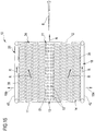
- the first zone 7 will include a corresponding conveyor 30 which can, by way of example, be defined by a conveyor belt as shown in figures 1 and 2 .
- This conveyor belt is generally more limited in its transversal dimensions relative to the transversal dimensions and respective conveyors of the second and third zones 8, 23 of the converger module 2.
- Figure 1 shows a single conveyor belt that runs along the whole converger module 2 from the inlet station 3 to the outlet station 4.
- the conveyor 30 may consist in a suitable belt 45 which bears a plurality of free rollers 46 rotating about their own axis 46a and which are appropriately positioned in respective cavities of the belt.
- the belt 45 will be made to advance along the indicated direction and the respective rollers 46 borne by the belt 45 will impart to the articles 5 resting thereon a movement that depends on the orientation of the rollers themselves.
- rollers 46 in the first zone 7 will be orientated in such a way as to impart only a movement R directed along the main advancement direction 6 towards the outlet station 4.
- the second zone 8 includes at least a conveying element 34 and in general a plurality of conveying elements for defining substantially a roller conveyor 35 whose rollers have an axis that is inclined relative to the main advancement direction 6 so as to impart the advancement motion towards the outlet station 4, and also the lateral movement 9a towards the first zone 7 (resultant R).
- rollers orientated substantially in the same direction, with axes thereof parallel to each other and also equidistant.
- the geometry of these rollers can also be varied so as to vary the pushing forces on the articles 5.
- a truncated cone shape could also be used for the geometry of the lateral surface of the rollers.
- the third zone 23 of the converger module 2 also comprises at least one respective conveying element 36 and in general a plurality of the elements 36 suitable for defining a respective roller conveyor 37 whose rollers have an axis that is inclined relative to the main advancement direction and is able to impart the advancement motion towards the outlet station 4 and also the lateral movement 9b towards the first zone 7 of the module (resultant R).
- the two roller conveyors 35 and 37 which in particular will have the same transversal and longitudinal dimensions, will be suitable for supportingly receiving the articles 5 and directing them towards the conveyor belt or central conveyor 30.
- roller conveyors 35, 37 are illustrated in figures 4 and 5 .
- each of the two lateral zones 8, 23 may be formed by a respective conveyor belt 47 affording the appropriate seatings within which a plurality of rollers 48 are mounted.
- the axis of inclination 48a of the rollers will be such as to define the forces applied on the articles placed on them.
- the articles 5 can be directed in such a way that movements are imparted to them along the main advancement direction 6 and also along a direction perpendicular thereto, so that they are directed, with a lateral movement 9a, 9b, towards the first zone 7 of the converger module (resultant R).
- the conveyor belts 45, 47 supporting the rollers 46, 48 may be separate and distinct ( figure 5 ) or even a single belt 49 ( figures 11 and 12 ) in which the various movements are imparted exclusively by mounting the idle rollers 46, 48 and directing the axes 46a, 48a as deemed appropriate.
- the motion of the rollers can be imparted in accordance with various embodiments, for example by making them roll (thanks to the motion of the belts they are mounted on) on surfaces 50 suitable for generating the rotation of the rollers due to the friction that is created.
- the first zone 7 can be placed at a lower average level L 1 , equal to or greater than L 2 , L 3 , of the corresponding second zone 8 and/or the corresponding third zone 23 of the converger module 2.
- figure 6 illustrates a situation in which the first zone 7 is at a level L 1 that is lower than both the second zone 8 and the third zone 23.
- figures 7 and 8 show that the presence of a lowered central zone 7 enables articles 5 of small transversal dimensions to be conveniently received and directed along the advancement direction 6 without any need for further intervention on the part of the device.
- Figure 9 shows the opposite situation where the first zone 7 lies in an average plane L 1 (rest surface for the articles) that is greater than the average plane L 2 , L 3 defined by the second zone 8 and/or the third zone 23.
- roller conveyors and the conveyor belt can also be obtained with the roller conveyors and the conveyor belt, by appropriately selecting the respective planes in which the articles rest/lie.
- roller conveyors having axes perpendicular to the direction 6 can be used in the second and third zones 8, 23, said roller conveyors being inclined, however, relative to the horizontal plane, towards the first zone 7 so that gravity defines the push towards the first zone 7, while the roller conveyors direct the articles exclusively towards the outlet station 4.
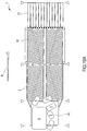
- a diverger module 10 is positioned following the converger module 2.
- the articles 5 handled by the converger module 2 are infed to the diverger module 10 at a respective inlet station 11.
- the diverger module 10 in general terms, also has a first zone 13 configured to receive the articles from the first zone 7 of the converger module 2 and to impart to the articles resting thereon an advancement motion along the main advancement direction 6.
- the first zone 13 of the diverger module 10 has, by way of non-limiting example, a rectangular profile when viewed from above, with the two longer sides parallel to the main advancement direction 6 and the opposite shorter sides positioned at the inlet and outlet stations 11 and 12.
- the first zone 13 of the diverger module will also be intended solely to impart this motion along the main advancement direction 6 from the inlet station 11 to the outlet station 12.
- the first zone 13 is generally defined by a respective conveyor 31, such as a conveyor belt, which can have and assume the same configurations as the conveyor belt or previously mentioned conveyor 30 belonging to the converger module 2.
- it can alternatively consist of a plurality of conveyor belts arranged in series along the advancement direction, or even, in an alternative embodiment, consist of the belt 51 having rollers 52 mounted idly and intended to impart the force R and the direction of advancement of the articles resting thereon.
- both the conveyor 30 of the converger module and the conveyor 31 of the diverger module 10 are configured to define, in cooperation with an article 5, a predetermined coefficient of friction that is greater than the respective coefficient of friction defined by the adjacent areas of the converger module 2 and diverger module 10.
- the same article 5 advancing in the first zones 7 and 13 will determine, in cooperation with the latter, a coefficient of friction that is greater than the coefficient of friction that the article 5 can determine with the various zones of the converger and/or diverger module.
- to identify such zones reference will be made, by way of non-limiting example, to zones having a high coefficient of friction, whereas for the adjacent zones reference will be made to zones having a low coefficient of friction.
- the diverger module 10 comprises a second zone 14 flanking the first zone 13 along the advancement direction 6.
- the second zone 14 extends between the inlet station 11 and the outlet station 12 and is defined, in a plan view, by a rectangular profile with the longer sides disposed parallel to the main advancement direction 6 and opposite shorter sides located at the inlet station 11 and the outlet station 12.
- the second zone 14 extends along a prevalent plane of extension which, under conditions of use of the singulator 1, is situated horizontally.
- the second zone 14 is configured to impart, to the articles resting thereon, an advancement motion along the main direction 6 and a lateral movement 15a away from the first zone 13 (resultant R) .
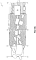
- the first zone 13 of the diverger module 10 projects, at least for a portion of its overall length (between the inlet station 11 and outlet station 12), away from a prevalent average plane of extension of the second zone 14 in the direction of the articles 5 to be supported, in order to define an ascent zone 15 of the diverger module 10.
- the ascent zone 15 comprises at least an ascending ramp 44a and a descending ramp 44b consecutively disposed along the advancement direction 6.
- the ascending ramp 44a extends, by way of non-limiting example, along a prevalent direction of extension which defines, with the prevalent average plane of extension of the second zone 14, a subtended angle comprised between 3° and 30°, in particular between 3° and 25°, and more in particular between 5° and 20°.
- the first ramp 44a extends inside an initial portion of the first zone 13 comprised within 50% of the total extent of said first zone 13, in particular within 30% of said first zone 13.
- the maximum difference in height of the ascent zone 15 is defined in the first 50% of the total extent of said first zone 13, in particular in the first 30% of said first zone 13.
- the latter also extends, by way of non-limiting example, along a prevalent direction of extension which defines, with the prevalent average plane of extension of the second zone 14, a subtended angle comprised between 3° and 30°, in particular between 3° and 25°, and more in particular between 5° and 20°.
- Figures 30 to 42 illustrate, by way of non-limiting example, an embodiment in which the ascending ramp 44a and descending ramp 44b are immediately consecutively disposed along the advancement direction 6 (i.e. there are no intermediate sections connecting said ramps 44a and 44b).
- the ascent zone defines, according to a longitudinal cross section, a substantially triangular profile (see for example the lateral figures 31 , 33 , 35 , 37 , 39 and 41 ).
- the ascent zone may comprise at least a connecting section interposed between the ascending ramp 44a and descending ramp 44b (condition not illustrated in the accompanying figures) and extending, for example, along a trajectory that is prevalently arch-shaped or rectilinear.
- the ascent zone 15 defines, with the second zone 14, a maximum difference in height greater than 2 cm, in particular comprised between 2 cm and 10 cm, even more in particular between 2 cm and 6 cm.
- the accompanying figures represent, by way of non-limiting example, a condition in which the difference in height defined by the ascent zone 15 is generated by the inclination of the ramps 44a and 44b relative to the second zone 14, which, under the conditions of use of the singulator 1, extend horizontally.
- the difference in height between the ascent zone 15 and the second zone 14 can also occur in the event that the latter is inclined downward relative to a horizontal plane (condition of use of the singulator 1), whereas the ascent zone extends horizontally (condition not illustrated in the accompanying figures).
- an ascent zone 15 in the diverger module 10 serves to ensure the separation (singulation) of the incoming articles in any configuration.
- the ascent zone 15 is particularly useful in cases where two or more articles 15 arriving from the converger module 2 are in a superimposed condition (one on top of the other).
- a normal singulator 1, having a first zone 13 that is coplanar with the adjacent zones, would not enable the articles 5 to be singulated in the latter described condition.
- the article 5 moving in the central zone 13 could exert upon an underlying article 5, in particular which it at least partially overlaps, a force tending to squash the latter and substantially prevent the zones adjacent to the first (central zone 13) from moving the article 5 away from the first zone, thus compromising the singulation thereof.
- the difference in height created by the ascent zone 15 enables the first zone 13 to place the advancing articles 5 on the different level thereon relative to the articles advancing in the adjacent zones, i.e. the zones 14 and 24; in this condition, should there be superimposed articles, one avoids squashing and consequently holding back articles advancing in the second and fourth zones 14, 24.
- the ascent zone 15 ensures that the articles 5 will slide on a level that is different from the level defined by the second and fourth zones 14, 24, thus avoiding, at least in that section, an interference of the articles 5 along a direction that is transversal, in particular perpendicular, to the plane of extension of the second and fourth zones 14, 24 (vertical direction in the condition of use of the singulator 1).
- the diverger module further has a third zone 16 flanking the second zone 14 along the main advancement direction 6 on the side opposite to the first zone 13.
- the second zone 14 of the diverger module 10 is interposed between and contiguous to the first zone 13 and the third zone 16, as shown in the accompanying figures.
- the third zone 16 is configured so that articles positioned therein are conveyed only along the advancement direction 6 until they reach the outlet station 12.
- the third zone 16 could begin anywhere between the inlet station 11 and the midpoint of the outlet station 12, as the converger module 2 will have brought the articles to the centre of the singulator.
- the diverger module 10 shown in figure 1 also has a fourth zone 24 extending between the inlet zone 11 and the outlet station 12 and flanking the first zone 13 along the main advancement direction 6 on a side opposite to the second zone 14.
- the fourth zone 24 also exhibits a rectangular profile with sides prevalently extending parallel to the main advancement direction 6 and opposite shorter sides positioned at the inlet station 11 and the outlet station 12.
- the fourth zone 24 is configured to impart to the articles resting thereon an advancement motion along the main advancement direction 6 and a lateral movement 15b away from the first zone 13.
- the lateral movement 15a, 15b imparted by the second zone 14 and the fourth zone 24 have the same direction but are respectively directed in the opposite way away from the first zone 13.
- the fourth zone 24 is substantially equal to the second zone 14 and in fact symmetrical to the latter relative to the zone 13: for these reasons, the ascent zone 15 projects equally from the fourth zone 24, thus defining the same difference in height.
- the second zone 14 and fourth zone 24 of the diverger module 10 comprise at least one respective conveying element 34, 36 and in particular a plurality of elements 34, 36 such as to define respective roller conveyors 35, 37 whose rollers have an axis that is inclined relative to the main advancement direction 6 so as to impart the above-mentioned advancement motion towards the outlet station 4 and the lateral movement 15a, 15b away from the first zone 13 of the diverger module 10.
- roller conveyors 35, 37 can be realised with axes inclined relative to the advancement direction in manner differing from the one illustrated, also differing from roller to roller and with a plurality of rollers having a cylindrical and/or truncated cone shape, and it will also obviously be possible to configure the second and the fourth zone of the diverger module using conveyor belts which have rollers mounted idly in respective cavities in the belts so as to impart the movements forward and away as previously described ( figures 15 and 16 ).
- the second and fourth zones 14, 24 will be structurally similar to the representations in figures 4 to 12 , the only difference being tied to the orientation of the axis of the rollers for generating the component 15a, 15b of moving away.
- the second and fourth zones 14, 24, too use can be made of roller conveyors having an axis perpendicular to the direction 6, but which are inclined relative to the horizontal plane in a direction away from the first zone 7, so that it is gravity which defines the component of pushing towards the third and fifth zones 16, 25, while the roller conveyors direct the articles exclusively towards the outlet station 12.
- the diverger module 10 further comprises at least a fifth zone 25 flanking the fourth zone 24 along the advancement direction 6 on the side opposite to the first zone 13.
- the articles in the fifth zone 25 are conveyed exclusively along the advancement direction 6 to the outlet station 12 (resultant R).
- the fifth zone 25 could begin anywhere between the inlet station 11 and the midpoint of the outlet station 12, as the converger module 2 will have brought the articles to the centre of the singulator.
- the third and the fifth zones 16, 25 of the diverger module 10 might be formed by a respective lateral wall 42, 43 which projects from an average plane of the diverger 10 ( figures 1 , 3 , 15 and 30 ).
- the lateral wall 42 will project from the average plane of the zone 14 and will be configured so as to supportingly receive the articles 5 pushed by the second zone 14 away from the first zone 13 and configured so as to enable conveyance along the main advancement direction 6 towards the outlet station 12.
- the lateral wall 42 extends longitudinally from a first end substantially disposed at the inlet station 11 and a second end substantially disposed at the outlet station 12.
- the second end of the lateral wall is at a distance from the first zone 13 that is less than the distance between the second end and said first zone 13: in this condition, the lateral wall 42 is divergent relative to the advancement direction 6.
- the lateral wall 42 at the first end thereof, has a connecting portion or an arch-shaped portion suitable for facilitating the arrival of articles from the converger module 2.
- the lateral wall 42 can be adjusted in position relative to the first zone 13; in particular it is adjustable in both inclination and distance relative to the first zone 13.
- the singulator comprises an activating device, namely, an electric motor or a piston suitable for moving the wall 42.
- the lateral wall 43 is identical to the lateral wall 42 and positioned symmetrically to the latter relative to the first zone 13.
- the lateral walls 42, 43 can consist of respective conveyor belts wherein the axis of rotation of the rollers on which they move is disposed perpendicular to the surface constituting the first, second and fourth zones of the diverger module; in other words, the belt will project vertically from the average plane of the diverger module.
- lateral walls 42 and 43 can generally be motorized so as to actively impart the motion towards the outlet station 12.
- the fifth zone 25 of the diverger module 10 will comprise the respective lateral wall 43 in a completely symmetrical and mirror-like manner relative to what was described above with reference to the lateral wall 42.
- the lateral walls 42 and 43 in the third zone 16 and the fifth zone 25 of the diverger module 10 may be replaced by the respective conveyor belts (in the same plane), for example with high friction and able to move the articles 5 which might arrive resting thereon exclusively along the main advancement direction 6.
- the conveyor belts may be replaced by conveyor belts having seatings with rollers mounted idly and suitable for directing the articles resting thereon exclusively in the main advancement direction 6.
- the conveyor belts may be replaced by conveyor belts having seatings with rollers mounted idly and suitable for directing the articles resting thereon exclusively in the main advancement direction 6.
- the selector module 17, too is illustrated immediately downstream of and disposed consecutively relative to the diverger module 10.
- the selector module 17 extends between a respective inlet station 18 and an outlet station 19 and has a respective first zone 20 configured to receive the articles arriving from the zone 13 of the diverger module 10 and to impart to the articles resting thereon an advancement motion exclusively along the main advancement direction 6 from the inlet station 18 to the outlet station 19.
- the selector module 17 further has a second zone 21 configured to receive the articles arriving from the third zone 16 of the diverger module 10 so as to impart, to the articles resting thereon, an advancement motion along the main advancement direction 6 (exclusively) from the inlet station 18 to the outlet station 19.
- the selector module 17 could also comprise a third zone 26 configured to receive the articles arriving from the fifth zone 25 of the diverger module 10 so as to impart, to the articles resting thereon, an advancement motion exclusively along the main advancement direction 6 from the inlet station 18 to the outlet station 19.
- Figure 1 illustrates the presence of a plurality of independent conveyor belts that define the direction of advancement of the articles positioned parallel to the main advancement direction 6.
- roller conveyors or rollers having axes perpendicular to the advancement direction can likewise be used, as can conveyor belts provided with cavities suitable for mounting idle rollers which direct the articles as mentioned above.
- the selector module 17 can be configured to comprise only moved conveyor belts positioned in the zones intended to receive the products exiting the diverger module 10 ( figure 17 ), or also a plurality of conveyor belts all moved independently of one another and placed side by side so that a control unit 22 can appropriately control the movement thereof ( figures 1 and 18 ) .
- Figure 1 illustrates the situation of a plurality of conveyor belts side by side;
- figure 17 illustrates a situation in which the selector module 17 comprises a fourth zone 28 flanking and interposed between the first and second zones 20, 21 along the main advancement direction 6 and a fifth zone 29 flanking and interposed between the first and the third zones 20, 26 along the main advancement direction 6.
- the fourth and fifth zones 28, 29 extend from the inlet station 18 to the outlet station 19 and comprise surfaces that are not moved, for example exhibiting low friction.
- the device also includes a control unit 22, which is active at least on the first zone 20 of the selector module 17 so as to impart the advancement motion along the main advancement direction 6 with an initial speed profile, and is also active at least in the second zone 21 of the selector module 17 so as to impart the corresponding advancement motion along the main advancement direction 6 with a second speed profile which can also be different from the first speed profile.
- a control unit 22 which is active at least on the first zone 20 of the selector module 17 so as to impart the advancement motion along the main advancement direction 6 with an initial speed profile, and is also active at least in the second zone 21 of the selector module 17 so as to impart the corresponding advancement motion along the main advancement direction 6 with a second speed profile which can also be different from the first speed profile.
- the control unit 22 will also be active in the third zone 26 of the selector module so as to impart thereon an advancement motion along the main advancement direction 6 with a third speed profile that can be different from both the first and the second speed profiles, as will be better explained below.
- the singulator is also equipped with a detection system 27 serving the control unit 22.
- This detection system 27 will be able to detect, over time, the passage of the articles 5 entering and/or in transit toward the selector module 17, at least in the first and second zones 20, 21 (and in general also the third zone 26).
- control unit 22 may also be a linear array of photocells along the line or the inlet station of the selector module so that the control unit 22 can receive the signal from each sensor of the detection system 27 and know the position and the passage time of the various articles 5 passing through the inlet station 18 of the selector module 17.
- the above-described embodiment can only use an arrangement of photocells at least in the first, second and third zones of the selector module 17 and in general throughout the line that defines the inlet station 18 of the module itself.
- other types of sensors can be used, such as one or more cameras ( figure 18 ) able not only to detect the shape of the product passing through the inlet station, but also to identify, for example from above, the profile of the article 5 and follow it in its advancing motion though the selector module 17 so that this type of movement can be actively controlled (see for example figure 18 ).
- control unit 22 receives the incoming signal/signals from the detection system 27 and uses them to determine the speed profiles to be assigned to the zones 20, 21 and 26 of the selector module 17.
- the speed profiles are set in order to enable products to be outfed from the outlet station 19 of the selector module 17 in a singulated configuration, i.e. not superimposed along the transversal extent of the selector module 17.
- control unit 22 is able to slow or stop the motion of the articles in the first zone 20 or in the second zone 21 so as to obtain the outfeed of a single product from the outlet station 19 before allowing the product present in the other zone or feed line to exit.
- the speed profile is appropriately changed (even bringing the speed to 0) in order to obtain a single outfeed of the products from the three feed lines A, B, C through the outlet station 19.
- the first zone 20 will be intended to receive the articles advancing along a main flow A, mainly coming from the first zone 13 of the diverger module 10.
- this zone 20 will have transversal dimensions that are greater than those of the remaining second and third zones 21, 26 and therefore could also receive, in certain situations, articles, for example of large dimensions, from the line B or C.
- this zone 20 comprises a respective conveyance device 53 provided with three conveyance surfaces 53a, 53b, 53c which can be distinguished at least on the basis of some structural and/or functional characteristics.
- all three conveyance surfaces of the first conveyance device 53 extend from the inlet station 18 to the outlet station 19 and are, in a view from above (see figure 23 ), of an elongated rectangular shape with larger opposite sides disposed parallel to the main advancement direction 6.
- conveyance surfaces 53a, 53b, 53c are side by side, adjacent to one another, with the first conveyance surface 53a being of larger transversal dimensions (about double) than the respective transversal dimensions of the conveyance surfaces 53b, 53c (in general equal to each other); the first surface 53a is interposed between the further surfaces.
- each of the conveyance surfaces 53a, 53b, 53c will be an area of active conveyance surface, i.e. a mobile conveyance surface suitable for generating, in an article totally or partly resting thereon, an advancement motion directed from the inlet station 18 to the outlet station 19 along the main advancement direction.
- the first conveyance surface 53a will have a coefficient of friction that is (much) higher than the corresponding coefficient of friction of the adjacent conveyance surfaces 53b, 53c.
- the three conveyance surfaces of the first device 53 will have an equivalent advancement speed from the inlet station 18 to the outlet station 19, as they will in general be moved by a same first conveyor device 53.
- conveyance surfaces 53a, 53b, 53c are shown that are distinct and separate from one another, but which could however all be defined by a single uninterrupted surface with areas that are distinct only in terms of their coefficient of friction.
- the example embodiment shown consists of three separate conveyor belts (endless belts) in continuous motion about at least two shafts having axes parallel to each other and arranged respectively along the lines defining the inlet station 18 and the outlet station 19.
- each of the conveyor belts 55, 56, 57 will be placed on these two shafts so as to impart, to the upper surface, a movement indicated by the arrows in figure 23 and directed along the main advancement direction 6.
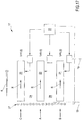
- the first movement system 58 is shown in figure 25 and comprises a motor 58a and a suitable transmission 58b (such as a gear reducer) that transmits motion via a belt around a respective shaft 66, about which the conveyor belts 55, 56, 57 rotate, thus being drawn by the shaft 66 which determines a constant advancement velocity that is substantially identical for the three aforementioned belts.
- a suitable transmission 58b such as a gear reducer
- the second zone 21 has a second motion transmission device 54 also defined by two conveyance surfaces 54a, 54b extending from the inlet station 18 to the outlet station 19 and having a rectangular shape when viewed from above, with the opposite longer sides positioned parallel to the main advancement direction 6.
- the conveyance surfaces 54a, 54b are positioned adjacent and side by side along the main direction of extension 6.
- the second conveyance surface 54b flanks and is adjacent to the second conveyance surface 53b of the first device 53 so as to define a substantially continuous support surface for the articles arriving from the diverger module.
- the first rest surface 54a will have a greater coefficient of friction than the second rest surface 54b.
- the illustrated embodiment includes two belts having substantially identical transversal dimensions, with the transversal dimensions of the second and third conveyance surfaces 53b, 53c of the first conveyance device 53 being substantially identical.
- the belts are two distinct conveyor belts 61, 62, the active surface of which defines the aforementioned conveyance surfaces 54a and 54b.
- the embodiment could consist of a single joined, uninterrupted belt that defines the two conveyance surfaces 54a and 54b with a different surface coefficient of friction.
- the second conveyance system 59 shown in figure 25 is substantially similar (and only differently positioned in the structure of the selector module 17) to the one previously mentioned.
- the system comprises a motor, for example an electric one 59a, and a transmission 59b (for example a gear reducer and a belt) which transmits motion to a shaft 67 active on the first and second conveyor belt 61, 62, previously mentioned.
- a motor for example an electric one 59a
- a transmission 59b for example a gear reducer and a belt
- the motor drives of the first conveyance device 53 and the second conveyance device 54 are independent and therefore also their speed of advancement will be independent (i.e. they can also be the same at certain moments, but will in any case be controlled and managed independently by the control unit 22).
- the belts could be moved at a constant speed, or, in contrast, be stationary, thus defining the speed profiles.
- the selector module 17 further comprises a third conveyance device 60, also having a first conveyance surface 60a and a second conveyance surface 60b.
- the conveyance surfaces extend from the inlet station 18 to the outlet station and have a substantially quadrangular shape with the longer sides thereof arranged parallel to the main advancement direction 6.
- the two conveyance surfaces 60a, 60b are positioned parallel and adjacent to each other.
- the second conveyance surface 60b is located adjacent to the third conveyance surface 53c of the first conveyance device 53.
- the first conveyance surface 60a will have a greater coefficient of friction than the second conveyance surface 60b of the third conveyance device 60.
- the surfaces can be obtained through the use of two distinct and separate elements (as shown) or even a single element with surface properties in terms of coefficient of friction on the two distinct surfaces.
- This embodiment as well comprises the use of two separate conveyor belts 64, 65, which are mounted on respective shafts positioned at the inlet and outlet stations 18 and 19 as previously described.
- the assembly described above will cover substantially the entire transversal extension of the selector module 17, while possibly leaving small gaps between the conveyor belts, which are not such, however, as to enable the occurrence of jamming or falls or otherwise cause problems of any sort to any of the products or the articles conveyable by the singulator.
- the third conveyance system 63 will have a respective motor 63b, in particular an electric motor, and a respective transmission 63a (a gear reducer and a belt); the transmission 63a will be active on a respective shaft 68 (see figure 26 ) in order to move the first and second surfaces 60a, 60b with the same advancement speed from the inlet station 18 to the outlet station 19.
- a respective motor 63b in particular an electric motor
- a respective transmission 63a (a gear reducer and a belt)
- the transmission 63a will be active on a respective shaft 68 (see figure 26 ) in order to move the first and second surfaces 60a, 60b with the same advancement speed from the inlet station 18 to the outlet station 19.
- the two conveyor belts 64, 65 will also move at the same forward speed, which being controlled independently, may be different, or in any case independent, both of the first advancement speed of the first conveyance device 53 and the advancement speed of the belts of the second conveyance device 54.
- conveyor belts 55, 56, 57, 61, 62, 64, 65 though the same functions might be obtained through the use of respective roller conveyors with different coefficients of friction (e.g. smooth rollers flanked by rubber-coated rollers); the various functions can also be obtained from a single continuous roller conveyor having axes of rotation that are perpendicular to the main advancement direction 6, in which the various above-described conveyance surfaces will differ due to portions having different coefficients of friction. It will also be possible to use conveyor belts having suitable holes in which idle rollers are mounted, and which also have different coefficients of friction according to the conveyance surfaces that they are intended to define.
- the surfaces of a same module (converger, diverger or selector) defining a coefficient of friction greater than that of other surfaces are placed in zones where a stream of articles is expected to be received according to the three advancement lines A, B, C.
- the conveyance surface 53a which is intended to receive the greatest flow of articles, will have larger dimensions so that the flow can be optimally managed; on the other hand, the surfaces intended to receive the articles arriving from the advancement lines B and C will have smaller transversal dimensions, as they will generally be designed to process a smaller number of articles.
- a product that might be, for example, in the advancement line B, and thus reach the first conveyance surface 54a, but which has very large transversal dimensions, such as to involve the other additional low-friction conveyance surfaces 54b and 53b, will receive a greater push from the higher-friction belt 54a, but also a contribution for pushing from the second conveyance surface 54b (and even if of a smaller entity). If, for any reason, the central zone 21 were not moved, the second conveyance surface 53b would be stationary, but they would not exhibit a high coefficient of friction and there would be a minimal influence on the conveyance and rotation of any product supported on the three conveyance surfaces mentioned above.
- Figures 19A to 19O are examples illustrating the operation of the singulator briefly described above.
- the converger module tends to bring the various articles 5 to the first zone 7, creating a first file or line of advancement of the singulated products.
- control unit 22 is aware of the exact positioning of the individual articles along the three advancement lines A, B, C.
- control unit 22 itself can differentiate the speed profiles of the three zones in which the three product lines are located in such a way as to achieve the outfeeed of a single product at a time from the outlet station 19 irrespective of whether superimposed articles along the transverse direction are on different lines (see the sequence of figures 19E to 19G , where the article 5b superimposed on the article 5a is halted until the former has completely exited).
- the products which are mainly on the central line A and possibly the auxiliary lines B and C are in any case longitudinally spaced from one another and can therefore be automatically managed and singulated in single file with known techniques.
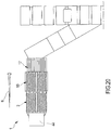
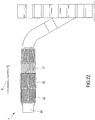
- figures 20 , 21 and 22 which illustrate, merely by way of example, a configuration with two singulators on the inlet side of a conveyance line ( figure 21 ) and also an individual singulator provided, downstream of the selector module 17, with an element having converging lateral walls for bringing the elements into single file.
- the singulator of the present description can also provide an opportunity to divert articles in transit after the articles themselves have passed through the converger module, diverger module and the selector module, should problems of a following type occur: products not singulated or introduced products which exceed the maximum size limit for processing in the subsequent stations.
- a switcher 100 is included, in particular a vertical switcher, i.e. a structure that can define a main advancement path (condition of normal use and advancement of articles) and a switching path in which the articles can be sent to a reject area.
- a vertical switcher i.e. a structure that can define a main advancement path (condition of normal use and advancement of articles) and a switching path in which the articles can be sent to a reject area.
- the vertical switcher 100 illustrated in figure 29 essentially consists of two conveyor belts 101, 102 tilting around respective opposite axes in such a manner as to define an aligned condition (generally the normal passage of the articles - figure 28 and direction 6a in figure 29 ) and an open configuration ( figure 29 - direction 6b) in which the respective ends, usually in proximity, of the first and second belts 101, 102 are vertically distanced and divert the flow of products.
- an aligned condition generally the normal passage of the articles - figure 28 and direction 6a in figure 29
- figure 29 - direction 6b open configuration
- What is described above enables control by activation, for example, by the control unit 22, of the opening/closing of the vertical switcher 100 and therefore the normal functioning or unloading of the products towards the unloading zone.
- the structure of the diverger module serves to ensure the separation, and consequently singulation, of articles irrespective of the condition in which the latter arrive from the converger module 2.
- the ascent zone 15 prevents the articles 5 advancing in the first zone 13 of the diverger module 10 and at least partially overlapping the articles advancing in the second and/or fourth zones 14 and 24 from squashing and holding back the latter: in this way it is possible to ensure that the latter articles will be moved away from the first zone 13.
- the singulator presented in its various embodiments is compact and involves modest costs.
- the singulating operations are obtained with a first part (converger module and diverger module) that is substantially mechanically active on the various articles in order to bring them from a loosely ordered condition into a condition in which the articles are arranged in only three advancement lines (a main line and two secondary lines).
- the electronic control part is minimized, thus increasing operational reliability, but at the same time ensuring a high level of flexibility, it being possible to manage a fine level of singulation in the selector module 17.
- the footprint of the whole device, in both the longitudinal and transversal directions, is rather modest while guaranteeing the ability to handle a rather high number of articles to be singulated per unit of time.
Description
- The present invention relates to a singulator, intended in particular to receive a plurality of incoming loose articles and to output the aforementioned plurality of articles, suitably singulated (in one or more lines), i.e. arranged consecutively along predetermined advancement lines.
- As is known, many commercial and industrial activities require a fixed number of articles that are generally fed randomly and are loosely ordered and then automatically sorted so that they can thereafter be handled more easily in an automatic or semiautomatic way.
- The machines designed for this operation are known as "singulators".
WO 2012/101576 A2 discloses singulators. The areas of use of singulators are varied, and include, by way of non-limiting example, the field of sorting and delivering mail, the dispatching and parcel distribution sector, etc. There are several devices on the market today suitable for the performance of the above-mentioned task. - A first type of these machines comprises, in the main structure thereof intended for singulating operations, the use of a first converger station consisting of a central high-friction conveyor belt flanked on both sides by two respective roller conveyors having axes that are inclined relative to the direction of advancement of the articles.
- The roller conveyors impart, to the articles resting thereon, an advancement motion and lateral translation towards the high-friction central belt, carrying the majority of articles onto the central belt itself.
- Located after the converger station there is a diverger station, which is also a high-friction central belt which follows on from the central belt of the converger station and is designed to receive the articles that have been brought to the central zone of the device.
- Flanking the central belt there are two roller conveyors which have rollers with inclined axes and are designed to impart to the articles entirely resting thereon an advancement motion and a corresponding lateral movement conveying them away from the high-friction central belt.
- In particular, an article that might be at least partially resting on the central belt would be conveyed thereby and would not be affected by the lateral thrust of the corresponding roller conveyor; in contrast, a product resting exclusively on the roller conveyor will be conveyed away from the central belt. Appropriate conveyor belts or recirculating belts are present at the sides of the diverger station, which belts are destined to receive the products that have been conveyed away from the diverger roller conveyors and return them to the inlet of the machine and in particular to the inlet of the converger station so that they can be newly processed.
- In contrast, the singulated products that are on the high-friction central belt proceed towards the further processing stations.
- In this way, the products are singulated at the central zone of the machine, while all the articles which, in particular due to being superimposed in a direction that is transversal to the conveyance direction, should they not reach the central zone, are advantageously recirculated via the diverger station, and via the recirculating belts they are returned to the machine inlet and then re-processed.
-
U.S. patent 5701989 describes, with particular reference tofigure 13 , a singulator according to the preamble ofclaim 1. The main difference is linked to the absence of a conveyor belt in the convergence zone (in other words there are only two roller conveyors converging towards the central advancement axis) and to the presence of a diverger station consisting of a plurality of additional conveyor belts with the aim of removing articles that are not singulated in such a way as to return them into the singulating cycle. - A second type of known devices suitable for singulating products is constituted by a complex apparatus in which all articles entering the device are suitably scanned by, for example, suitable cameras which can provide the read information to a control unit that reconstructs the distribution of the articles along the advancement pathway thereof.
- In particular, a movement surface is present, consisting of an array of individual conveyor belts, all independently movable.
- In other words, the movement surface consists of a fixed number of rows and columns defined by a plurality of individual conveyor belts which are driven by the control unit via respective motors. As the control unit has the position of the single articles in its memory, and is monitoring the movements, it drives the conveyor belts at differentiated speeds, so as to be able to suitably orientate the articles by rotating them, and also to be able to space them apart in the longitudinal direction by differentiating the advancement speeds of the belts on which the articles are resting.
- When leaving the deck, the various articles will be orientated in an orderly manner and will be sufficiently spaced along their respective advancement lines.
- In this way, it will be possible to operate downstream of the surface along which the articles move, as they are already pre-ordered, and perform thereon a final singulation.
- The above-mentioned machine is at least partially described in some patent publications, for example, in patents
EP 1556297 andU.S. 2003/141165 . - The singulators briefly described above, while admirably fulfilling the tasks they are designed for, are not free from limitations and/or operational problems.
- For example, the singulators described above are not able to assure the correct singulation of articles in the event that two or more of said articles are superimposed on one another. Moreover, as regards the singulator having the converger station, the diverger station and the recirculating belt, the latter is extremely large, both longitudinally and transversally.
- In fact, the operating principle requires that all the products be carried on the central singulating conveyor belt, and implies the need to have predetermined lengths in the conveyance direction so as to ensure adequate filling of the high-friction central belt.
- Furthermore, the need to be able to recirculate products that have not been singulated requires the presence of two further recirculating belts positioned at the sides of the machine, which obviously increases the dimensions thereof in that direction. What is described above generally implies the need to have large volumes/dimensions in order to install the singulators in question, resulting in increases in the costs of both constructing the device and managing the machine itself.
- On the other hand, as the device has a multiplicity of conveyor belts that are independently movable, it is much more compact, but at the same time, extremely complex in terms of the construction and management of the operation thereof.
- Indeed, it is necessary to set up a control unit and cameras to monitor the movement of the articles, as well as a control algorithm that can enable efficient and individual operation in a controlled manner on each of the conveyor belts.
- Furthermore, each of the conveyor belts is equipped with a respective drive and a respective motor, which clearly increase the costs of construction and maintenance, while at the same time reducing the reliability of the singulator (considering the high number of electrical and mechanical parts that make it up) .
- The object of the present invention is thus to substantially resolve at least one of the drawbacks and/or limitations of the previous solutions.
- A first aim of the singulator, of which various embodiments are described below, is to provide a machine that is capable of assuring an effective singulation of articles, and in particular of assuring, in a diverger module, the separation of articles also in the event that at least two of them are vertically superimposed on one another.
- A further aim of the singulator is to provide a machine that is sufficiently compact and at the same time fairly simple from the point of view of management and control.
- One objective is to limit the active control functions required for singulating, thus also limiting the number of motors (and the consequent electronics), as well as the mechanical parts in motion.
- Lastly, a further aim is to contain not only the transversal dimensions of the device, but also the longitudinal dimensions, by providing a singulator able to guarantee good singulating performances in terms of a maximum number of articles that can be singulated per unit of time and in terms of reliability of singulation.
- One or more of the above-described objects, which will become more apparent from the following description, are substantially attained by a singulator according to one or more of the accompanying claims.
- Some embodiments and some aspects of the invention will be described below with reference to the appended drawings, provided solely by way of non-limiting example, in which:
-

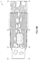
figure 1 illustrates a first embodiment of a singulator described hereunder; -
figure 2 illustrates a variant of the singulator offigure 1 ; -
figure 3 illustrates a further variant of the singulator offigure 1 ; -
figure 4 illustrates a possible variant of the converger module; -
figure 5 illustrates a possible further variant of the converger module; -
figure 6 shows a cross section of the converger module offigure 5 ; -
figures 7 and 8 schematically show the different behaviour of the module offigures 4 and5 ; -
figures 9 ,11 and 12 are section views of three different embodiments of the converger module; -
figure 10 schematically shows the functioning of a module according tofigure 9 ; -
figures 13-16 illustrate four possible variants of the diverger module; -
figures 17 and18 illustrate two possible variants of the selector module; -
figures 19A to 19O show an operating sequence of the singulator in successive instants of time; -
figures 20 ,21 and22 show three possible variants of systems comprising the singulator to which the description relates; -
figure 23 is a view from above of a selector module according to an alternative and advantageous embodiment; -
figures 24 ,25 ,26 are further views of the selector offigure 23 with some parts removed in order better to illustrate others; -
figure 27 is a perspective view of the singulator in a further embodiment; -
figure 28 shows an overall view of a singulator included in a plant for treating articles; and -
figure 29 shows the vertical switcher offigure 28 . -
figure 30 is a perspective view of a possible embodiment of the diverger module of a singulator according to the present invention; -
figures 31 to 42 show an operating sequence of the singulator in successive instants of time. - With reference to the aforesaid
figures, 1 denotes in its entirety a singulator as described below. - In particular, and as previously mentioned, the singulator that is the subject matter of the following description is particularly intended for the singulation of loosely arranged
items 5. - In particular, the
articles 5, which may have undergone further manipulation if necessary before reaching the inlet of the singulator (e.g. unstacking operations for supplying them to the inlet in a two-dimensional configuration) are brought to the inlet of the singulator by a suitable conveyor belt (or equivalent system) for infeeding them to the main modules of the singulator. - In particular, the products initially reach an
inlet station 3 of aconverger module 2. - The
converger module 2 extends longitudinally along amain direction 6 of advancement of the articles between the above-mentionedinlet station 3 and an outlet station 4. - In general, the
loose articles 5 entering theconverger module 2 will be conveyed (and appropriately handled) starting from theinlet station 3 along the main advancement direction up until reaching the outlet station 4, so as to be received by successive modules of the singulator. - Observing in particular the figures and the various embodiments, it can be seen that, in general terms, the
converger module 2 primarily features at least afirst zone 7 defined between theinlet station 3 and the outlet station 4 along the main advancement or conveyance direction of thearticles 6. - This
zone 7 will generally, in a view from above, have a rectangular profile with a main geometry that extends substantially parallel to the main direction ofextension 6, and with the two opposite shorter sides located at the inlet andoutlet stations 3 and 4. - This
zone 7 will be generally configured so as to impart to the articles resting thereon a direct advancement motion exclusively along the main advancement direction 6 (see for examplefigure 1 ). In other words, thefirst zone 7 will include at least one conveyor configured so as to impart this movement to thearticles 5. - Alternatively (see
figure 3 ) the first zone 7 (i.e. the corresponding conveyor) may be configured so as to impart to thearticles 5 resting thereon not only an advancement motion along themain direction 6, but also alateral movement 9b in a direction perpendicular to the advancement direction directed towards asecond zone 8. In other words, the conveyor will be able to impart a parallel motion to the articles or, in an alternative embodiment, a motion directionally inclined (resultant R in the figures) relative to the main advancement direction 6 (or to the main axis of extension of the singulator). Once more from a general point of view, theconverger module 2 also features asecond zone 8 which flanks thefirst zone 7 along themain advancement direction 6 and also extends between theinlet station 3 and the outlet station 4 of themodule 2. - The
second zone 8 is configured to impart to thearticles 5 resting thereon an advancement motion along themain direction 6 and also alateral movement 9a in the direction of thefirst zone 7. - In this regard, the
second zone 8 will include at least one conveyor (and in general a plurality thereof) configured to impart the described movement to the articles (inclined; resultant R). - This
second zone 8, in a view from above, also has a rectangular profile extending mainly in a direction parallel to themain advancement direction 6, and with the shorter opposite sides positioned at theinlet station 3 and the outlet station 4. - In particular, the two corresponding longer sides of the
first zone 7 and thesecond zone 8, are side by side and facing each other. - In the majority of the illustrated embodiments (except for
figures 2 and3 ) theconverger module 2 also includes athird zone 23 flanking thefirst zone 7 along themain advancement direction 6 and positioned on the side opposite to thesecond zone 8. - In general, the
first zone 7 will therefore be interposed between thesecond zone 8 and thethird zone 23; the threezones figure 1 for example. - The
third zone 23 also extends between theinlet station 3 and the outlet station 4 and exhibits, in a view from above, a substantially rectangular profile with the longer sides directed along themain advancement direction 6 and shorter sides that are opposite and positioned at the inlet andoutlet stations 3 and 4. Thethird zone 23 is configured to impart to thearticles 5 resting thereon an advancement motion along themain direction 6 and also alateral movement 9b in the direction of thefirst zone 7; in particular, thelateral movements second zone 8 and thethird zone 23 have the same direction (perpendicular to the main direction 6) and are respectively directed in the opposite way towards thefirst zone 7. - In still other words, the
second zone 8 and thethird zone 23 impart, to the articles resting thereon, not only an advancement motion towards the outlet station 4, but also a lateral movement serving to convey the articles towards the firstcentral zone 7; the resultant force on the articles is denoted by R. - From the point of view of realisation, the
first zone 7 will include a correspondingconveyor 30 which can, by way of example, be defined by a conveyor belt as shown infigures 1 and2 . - This conveyor belt is generally more limited in its transversal dimensions relative to the transversal dimensions and respective conveyors of the second and
third zones converger module 2. -
Figure 1 (and the following figures) shows a single conveyor belt that runs along thewhole converger module 2 from theinlet station 3 to the outlet station 4. - Obviously two or more belts having longitudinal dimensions that are more modest may be present, consecutively arranged and aligned with one another.
- In a further variant, illustrated for example in
figures 4 and5 , theconveyor 30 may consist in asuitable belt 45 which bears a plurality offree rollers 46 rotating about theirown axis 46a and which are appropriately positioned in respective cavities of the belt. - In other words, the
belt 45 will be made to advance along the indicated direction and therespective rollers 46 borne by thebelt 45 will impart to thearticles 5 resting thereon a movement that depends on the orientation of the rollers themselves. - In particular, as shown in
figure 5 , therollers 46 in thefirst zone 7 will be orientated in such a way as to impart only a movement R directed along themain advancement direction 6 towards the outlet station 4. - With reference to the
second zone 8 of theconverger module 2, it can be seen that thesecond zone 8 includes at least a conveyingelement 34 and in general a plurality of conveying elements for defining substantially aroller conveyor 35 whose rollers have an axis that is inclined relative to themain advancement direction 6 so as to impart the advancement motion towards the outlet station 4, and also thelateral movement 9a towards the first zone 7 (resultant R). - The figures show rollers orientated substantially in the same direction, with axes thereof parallel to each other and also equidistant.
- However, it should be noted that the above configuration is disclosed and illustrated solely by way of example, as variously spaced rollers might well be used, respectively inclined in a more or less accentuated manner relative to the
main advancement direction 6. - The geometry of these rollers, generally cylindrical, can also be varied so as to vary the pushing forces on the
articles 5. Purely by way of example, a truncated cone shape could also be used for the geometry of the lateral surface of the rollers. Thethird zone 23 of theconverger module 2 also comprises at least one respective conveyingelement 36 and in general a plurality of theelements 36 suitable for defining arespective roller conveyor 37 whose rollers have an axis that is inclined relative to the main advancement direction and is able to impart the advancement motion towards the outlet station 4 and also thelateral movement 9b towards thefirst zone 7 of the module (resultant R). - In other words, the two
roller conveyors articles 5 and directing them towards the conveyor belt orcentral conveyor 30. - In this case, too, an alternative embodiment of the
roller conveyors figures 4 and5 . - As with the
first zone 7, each of the twolateral zones respective conveyor belt 47 affording the appropriate seatings within which a plurality ofrollers 48 are mounted. - As previously mentioned, the axis of
inclination 48a of the rollers will be such as to define the forces applied on the articles placed on them. - In particular, by appropriately tilting the axis of rotation relative to the advancement direction of the
belts 47 thearticles 5 can be directed in such a way that movements are imparted to them along themain advancement direction 6 and also along a direction perpendicular thereto, so that they are directed, with alateral movement first zone 7 of the converger module (resultant R). - It should also be noted that the
conveyor belts rollers figure 5 ) or even a single belt 49 (figures 11 and 12 ) in which the various movements are imparted exclusively by mounting theidle rollers axes surfaces 50 suitable for generating the rotation of the rollers due to the friction that is created. - In a possible configuration that has certain advantages, the
first zone 7 can be placed at a lower average level L1, equal to or greater than L2, L3, of the correspondingsecond zone 8 and/or the correspondingthird zone 23 of theconverger module 2. - In particular,
figure 6 illustrates a situation in which thefirst zone 7 is at a level L1 that is lower than both thesecond zone 8 and thethird zone 23. - The difference in effects with respect to planar zones is shown in
figures 7 and 8 , which show that the presence of a loweredcentral zone 7 enablesarticles 5 of small transversal dimensions to be conveniently received and directed along theadvancement direction 6 without any need for further intervention on the part of the device. -
Figure 9 shows the opposite situation where thefirst zone 7 lies in an average plane L1 (rest surface for the articles) that is greater than the average plane L2, L3 defined by thesecond zone 8 and/or thethird zone 23. - In this case the effect is illustrated in
figure 10 , where it can be observed that in the presence of articles having larger transversal dimensions than thefirst zone 7, the positioning thereof is improved. - It should be noted, moreover (
figures 11 and 12 ), that the different heights of thefirst zone 7 relative to theadjacent zones same conveyor belt 49 and by varying the heights of theindividual rollers - Obviously, the above-described effects can also be obtained with the roller conveyors and the conveyor belt, by appropriately selecting the respective planes in which the articles rest/lie. Alternatively, roller conveyors having axes perpendicular to the
direction 6 can be used in the second andthird zones first zone 7 so that gravity defines the push towards thefirst zone 7, while the roller conveyors direct the articles exclusively towards the outlet station 4. - A
diverger module 10 is positioned following theconverger module 2. - The accompanying figures represent, by way of non-limiting examples, the two
modules - In any event, the
articles 5 handled by theconverger module 2 are infed to thediverger module 10 at arespective inlet station 11. - The
diverger module 10, in general terms, also has afirst zone 13 configured to receive the articles from thefirst zone 7 of theconverger module 2 and to impart to the articles resting thereon an advancement motion along themain advancement direction 6. - In this case too, the
first zone 13 of thediverger module 10 has, by way of non-limiting example, a rectangular profile when viewed from above, with the two longer sides parallel to themain advancement direction 6 and the opposite shorter sides positioned at the inlet andoutlet stations - The
first zone 13 of the diverger module will also be intended solely to impart this motion along themain advancement direction 6 from theinlet station 11 to theoutlet station 12. - The
first zone 13 is generally defined by arespective conveyor 31, such as a conveyor belt, which can have and assume the same configurations as the conveyor belt or previously mentionedconveyor 30 belonging to theconverger module 2. - In particular, it can alternatively consist of a plurality of conveyor belts arranged in series along the advancement direction, or even, in an alternative embodiment, consist of the
belt 51 havingrollers 52 mounted idly and intended to impart the force R and the direction of advancement of the articles resting thereon. - It should be noted that in general, although not necessarily, both the
conveyor 30 of the converger module and theconveyor 31 of thediverger module 10 are configured to define, in cooperation with anarticle 5, a predetermined coefficient of friction that is greater than the respective coefficient of friction defined by the adjacent areas of theconverger module 2 anddiverger module 10. In fact, thesame article 5 advancing in thefirst zones article 5 can determine with the various zones of the converger and/or diverger module. In the discussion that follows, to identify such zones reference will be made, by way of non-limiting example, to zones having a high coefficient of friction, whereas for the adjacent zones reference will be made to zones having a low coefficient of friction. - In this way, it is ensured that an
article 5, partially resting in thefirst zone 7 of theconverger module 2 or thefirst zone 13 of thediverger module 10, will mainly receive the motion imparted by the zone itself and will therefore be exclusively directed along themain advancement direction 6. - Once again from a general point of view, the
diverger module 10 comprises asecond zone 14 flanking thefirst zone 13 along theadvancement direction 6. - The
second zone 14 extends between theinlet station 11 and theoutlet station 12 and is defined, in a plan view, by a rectangular profile with the longer sides disposed parallel to themain advancement direction 6 and opposite shorter sides located at theinlet station 11 and theoutlet station 12. In particular, thesecond zone 14 extends along a prevalent plane of extension which, under conditions of use of thesingulator 1, is situated horizontally. - The
second zone 14 is configured to impart, to the articles resting thereon, an advancement motion along themain direction 6 and alateral movement 15a away from the first zone 13 (resultant R) . - As can be seen from figures 32 to 42, the
first zone 13 of thediverger module 10 projects, at least for a portion of its overall length (between theinlet station 11 and outlet station 12), away from a prevalent average plane of extension of thesecond zone 14 in the direction of thearticles 5 to be supported, in order to define anascent zone 15 of thediverger module 10. - In accordance with the present invention, the
ascent zone 15 comprises at least an ascendingramp 44a and adescending ramp 44b consecutively disposed along theadvancement direction 6. The ascendingramp 44a extends, by way of non-limiting example, along a prevalent direction of extension which defines, with the prevalent average plane of extension of thesecond zone 14, a subtended angle comprised between 3° and 30°, in particular between 3° and 25°, and more in particular between 5° and 20°. - In a preferred, but non-limiting embodiment, the
first ramp 44a extends inside an initial portion of thefirst zone 13 comprised within 50% of the total extent of saidfirst zone 13, in particular within 30% of saidfirst zone 13. - In the latter configuration described, the maximum difference in height of the
ascent zone 15 is defined in the first 50% of the total extent of saidfirst zone 13, in particular in the first 30% of saidfirst zone 13. - With regard to the
descending ramp 44b, the latter also extends, by way of non-limiting example, along a prevalent direction of extension which defines, with the prevalent average plane of extension of thesecond zone 14, a subtended angle comprised between 3° and 30°, in particular between 3° and 25°, and more in particular between 5° and 20°. -
Figures 30 to 42 illustrate, by way of non-limiting example, an embodiment in which theascending ramp 44a and descendingramp 44b are immediately consecutively disposed along the advancement direction 6 (i.e. there are no intermediate sections connecting saidramps figures 31 ,33 ,35 ,37 ,39 and41 ). - Alternatively, the ascent zone may comprise at least a connecting section interposed between the ascending
ramp 44a and descendingramp 44b (condition not illustrated in the accompanying figures) and extending, for example, along a trajectory that is prevalently arch-shaped or rectilinear. - From a dimensional standpoint, the
ascent zone 15 defines, with thesecond zone 14, a maximum difference in height greater than 2 cm, in particular comprised between 2 cm and 10 cm, even more in particular between 2 cm and 6 cm. - The accompanying figures represent, by way of non-limiting example, a condition in which the difference in height defined by the
ascent zone 15 is generated by the inclination of theramps second zone 14, which, under the conditions of use of thesingulator 1, extend horizontally. However, the difference in height between theascent zone 15 and thesecond zone 14 can also occur in the event that the latter is inclined downward relative to a horizontal plane (condition of use of the singulator 1), whereas the ascent zone extends horizontally (condition not illustrated in the accompanying figures). - Overall it is possible to identify a difference in height between the
ascent zone 15 and thesecond zone 14 in conditions wherein thefirst ramp 44a defines, under conditions of use of thesingulator 1, relative to a horizontal plane, a subtended angle that is greater than the subtended angle which the second portion defines with said horizontal plane. - The fact of including an
ascent zone 15 in thediverger module 10 serves to ensure the separation (singulation) of the incoming articles in any configuration. In greater detail, theascent zone 15 is particularly useful in cases where two ormore articles 15 arriving from theconverger module 2 are in a superimposed condition (one on top of the other). Anormal singulator 1, having afirst zone 13 that is coplanar with the adjacent zones, would not enable thearticles 5 to be singulated in the latter described condition. In fact, thearticle 5 moving in thecentral zone 13 could exert upon anunderlying article 5, in particular which it at least partially overlaps, a force tending to squash the latter and substantially prevent the zones adjacent to the first (central zone 13) from moving thearticle 5 away from the first zone, thus compromising the singulation thereof. - The movement of the superimposed
articles 5 in motion on the diverger can be clearly seen infigures 31 to 42 . - The difference in height created by the
ascent zone 15 enables thefirst zone 13 to place the advancingarticles 5 on the different level thereon relative to the articles advancing in the adjacent zones, i.e. thezones fourth zones - In short, the
ascent zone 15 ensures that thearticles 5 will slide on a level that is different from the level defined by the second andfourth zones articles 5 along a direction that is transversal, in particular perpendicular, to the plane of extension of the second andfourth zones 14, 24 (vertical direction in the condition of use of the singulator 1). - As can be seen from the accompanying figures, the diverger module further has a
third zone 16 flanking thesecond zone 14 along themain advancement direction 6 on the side opposite to thefirst zone 13. - In still other words, the
second zone 14 of thediverger module 10 is interposed between and contiguous to thefirst zone 13 and thethird zone 16, as shown in the accompanying figures. - The
third zone 16 is configured so that articles positioned therein are conveyed only along theadvancement direction 6 until they reach theoutlet station 12. - The
third zone 16 could begin anywhere between theinlet station 11 and the midpoint of theoutlet station 12, as theconverger module 2 will have brought the articles to the centre of the singulator. - It should also be noted that the
diverger module 10 shown infigure 1 also has afourth zone 24 extending between theinlet zone 11 and theoutlet station 12 and flanking thefirst zone 13 along themain advancement direction 6 on a side opposite to thesecond zone 14. - In a plan view, the
fourth zone 24 also exhibits a rectangular profile with sides prevalently extending parallel to themain advancement direction 6 and opposite shorter sides positioned at theinlet station 11 and theoutlet station 12. - The
fourth zone 24 is configured to impart to the articles resting thereon an advancement motion along themain advancement direction 6 and alateral movement 15b away from thefirst zone 13. - In other words, the
lateral movement second zone 14 and thefourth zone 24 have the same direction but are respectively directed in the opposite way away from thefirst zone 13. - From a structural standpoint, the
fourth zone 24 is substantially equal to thesecond zone 14 and in fact symmetrical to the latter relative to the zone 13: for these reasons, theascent zone 15 projects equally from thefourth zone 24, thus defining the same difference in height. - In this case, too, the
second zone 14 andfourth zone 24 of thediverger module 10 comprise at least one respective conveyingelement elements respective roller conveyors main advancement direction 6 so as to impart the above-mentioned advancement motion towards the outlet station 4 and thelateral movement first zone 13 of thediverger module 10. - As previously mentioned, the illustration is by way of non-limiting example and therefore the
roller conveyors figures 15 and16 ). - In the latter case, the second and
fourth zones figures 4 to 12 , the only difference being tied to the orientation of the axis of the rollers for generating thecomponent fourth zones direction 6, but which are inclined relative to the horizontal plane in a direction away from thefirst zone 7, so that it is gravity which defines the component of pushing towards the third andfifth zones outlet station 12. Thediverger module 10 further comprises at least afifth zone 25 flanking thefourth zone 24 along theadvancement direction 6 on the side opposite to thefirst zone 13. - In this case, too, the articles in the
fifth zone 25 are conveyed exclusively along theadvancement direction 6 to the outlet station 12 (resultant R). - The
fifth zone 25 could begin anywhere between theinlet station 11 and the midpoint of theoutlet station 12, as theconverger module 2 will have brought the articles to the centre of the singulator. - It should be noted that the third and the
fifth zones diverger module 10 might be formed by a respectivelateral wall figures 1 ,3 ,15 and30 ). - In particular, in the case of the
third zone 16 of thediverger module 10, thelateral wall 42 will project from the average plane of thezone 14 and will be configured so as to supportingly receive thearticles 5 pushed by thesecond zone 14 away from thefirst zone 13 and configured so as to enable conveyance along themain advancement direction 6 towards theoutlet station 12. - In a preferred, but non-limiting embodiment, the
lateral wall 42 extends longitudinally from a first end substantially disposed at theinlet station 11 and a second end substantially disposed at theoutlet station 12. Advantageously, the second end of the lateral wall is at a distance from thefirst zone 13 that is less than the distance between the second end and said first zone 13: in this condition, thelateral wall 42 is divergent relative to theadvancement direction 6. As can be seen fromfigure 30 , thelateral wall 42, at the first end thereof, has a connecting portion or an arch-shaped portion suitable for facilitating the arrival of articles from theconverger module 2. Preferably, thelateral wall 42 can be adjusted in position relative to thefirst zone 13; in particular it is adjustable in both inclination and distance relative to thefirst zone 13. In order to adjust thelateral wall 42, the singulator comprises an activating device, namely, an electric motor or a piston suitable for moving thewall 42. - Preferably, by way of non-limiting example, the
lateral wall 43 is identical to thelateral wall 42 and positioned symmetrically to the latter relative to thefirst zone 13. - The
lateral walls - In addition, the
lateral walls outlet station 12. - Obviously, the
fifth zone 25 of thediverger module 10 will comprise the respectivelateral wall 43 in a completely symmetrical and mirror-like manner relative to what was described above with reference to thelateral wall 42. - In an alternative embodiment illustrated in
figure 13 , thelateral walls third zone 16 and thefifth zone 25 of thediverger module 10 may be replaced by the respective conveyor belts (in the same plane), for example with high friction and able to move thearticles 5 which might arrive resting thereon exclusively along themain advancement direction 6. - According to a further alternative (
figure 16 ) the conveyor belts may be replaced by conveyor belts having seatings with rollers mounted idly and suitable for directing the articles resting thereon exclusively in themain advancement direction 6. Combinations of the above solutions will also be possible, see for examplefigure 14 in which a projectinglateral wall 43 and a conveyor belt on the opposite side are used. - Observing the singulator shown in
figure 1 , one may note the presence of aselector module 17 located downstream of thediverger module 10 along themain advancement direction 6. - As per the previous description, the
selector module 17, too, is illustrated immediately downstream of and disposed consecutively relative to thediverger module 10. - However, an intermediate transfer module might be present, which could still enable the
selector module 17 to function optimally without going outside the scope of the inventive concept as described. - In any case, the
selector module 17 extends between arespective inlet station 18 and anoutlet station 19 and has a respectivefirst zone 20 configured to receive the articles arriving from thezone 13 of thediverger module 10 and to impart to the articles resting thereon an advancement motion exclusively along themain advancement direction 6 from theinlet station 18 to theoutlet station 19. - The
selector module 17 further has asecond zone 21 configured to receive the articles arriving from thethird zone 16 of thediverger module 10 so as to impart, to the articles resting thereon, an advancement motion along the main advancement direction 6 (exclusively) from theinlet station 18 to theoutlet station 19. - Furthermore, the
selector module 17 could also comprise athird zone 26 configured to receive the articles arriving from thefifth zone 25 of thediverger module 10 so as to impart, to the articles resting thereon, an advancement motion exclusively along themain advancement direction 6 from theinlet station 18 to theoutlet station 19. -
Figure 1 illustrates the presence of a plurality of independent conveyor belts that define the direction of advancement of the articles positioned parallel to themain advancement direction 6. As an alternative to conveyor belts, roller conveyors or rollers having axes perpendicular to the advancement direction can likewise be used, as can conveyor belts provided with cavities suitable for mounting idle rollers which direct the articles as mentioned above. - Furthermore, the
selector module 17 can be configured to comprise only moved conveyor belts positioned in the zones intended to receive the products exiting the diverger module 10 (figure 17 ), or also a plurality of conveyor belts all moved independently of one another and placed side by side so that acontrol unit 22 can appropriately control the movement thereof (figures 1 and18 ) .Figure 1 illustrates the situation of a plurality of conveyor belts side by side;figure 17 , on the other hand, illustrates a situation in which theselector module 17 comprises afourth zone 28 flanking and interposed between the first andsecond zones main advancement direction 6 and afifth zone 29 flanking and interposed between the first and thethird zones main advancement direction 6. - The fourth and
fifth zones inlet station 18 to theoutlet station 19 and comprise surfaces that are not moved, for example exhibiting low friction. - As can be observed from the accompanying
figure 17 , the device also includes acontrol unit 22, which is active at least on thefirst zone 20 of theselector module 17 so as to impart the advancement motion along themain advancement direction 6 with an initial speed profile, and is also active at least in thesecond zone 21 of theselector module 17 so as to impart the corresponding advancement motion along themain advancement direction 6 with a second speed profile which can also be different from the first speed profile. - The
control unit 22 will also be active in thethird zone 26 of the selector module so as to impart thereon an advancement motion along themain advancement direction 6 with a third speed profile that can be different from both the first and the second speed profiles, as will be better explained below. - In detail, and as shown in the accompanying figures, the singulator is also equipped with a
detection system 27 serving thecontrol unit 22. - This
detection system 27 will be able to detect, over time, the passage of thearticles 5 entering and/or in transit toward theselector module 17, at least in the first andsecond zones 20, 21 (and in general also the third zone 26). - Purely by way of example, there may also be a linear array of photocells along the line or the inlet station of the selector module so that the
control unit 22 can receive the signal from each sensor of thedetection system 27 and know the position and the passage time of thevarious articles 5 passing through theinlet station 18 of theselector module 17. - The above-described embodiment can only use an arrangement of photocells at least in the first, second and third zones of the
selector module 17 and in general throughout the line that defines theinlet station 18 of the module itself. Alternatively, or in combination, other types of sensors can be used, such as one or more cameras (figure 18 ) able not only to detect the shape of the product passing through the inlet station, but also to identify, for example from above, the profile of thearticle 5 and follow it in its advancing motion though theselector module 17 so that this type of movement can be actively controlled (see for examplefigure 18 ). - As mentioned, the
control unit 22 receives the incoming signal/signals from thedetection system 27 and uses them to determine the speed profiles to be assigned to thezones selector module 17. - In particular, the speed profiles are set in order to enable products to be outfed from the
outlet station 19 of theselector module 17 in a singulated configuration, i.e. not superimposed along the transversal extent of theselector module 17. - As better explained below, should two articles be in the
selector module 17, for example in the first andsecond zones control unit 22 is able to slow or stop the motion of the articles in thefirst zone 20 or in thesecond zone 21 so as to obtain the outfeed of a single product from theoutlet station 19 before allowing the product present in the other zone or feed line to exit. - In other words, the speed profile is appropriately changed (even bringing the speed to 0) in order to obtain a single outfeed of the products from the three feed lines A, B, C through the
outlet station 19. - With reference to the
selector module 17, an extremely interesting third embodiment thereof is illustrated infigures 23 to 26 . - In particular, and as previously mentioned, the
first zone 20 will be intended to receive the articles advancing along a main flow A, mainly coming from thefirst zone 13 of thediverger module 10. - In reality, this
zone 20 will have transversal dimensions that are greater than those of the remaining second andthird zones first zone 20, one may see that it comprises arespective conveyance device 53 provided with threeconveyance surfaces - In particular, all three conveyance surfaces of the
first conveyance device 53 extend from theinlet station 18 to theoutlet station 19 and are, in a view from above (seefigure 23 ), of an elongated rectangular shape with larger opposite sides disposed parallel to themain advancement direction 6. - These conveyance surfaces 53a, 53b, 53c are side by side, adjacent to one another, with the
first conveyance surface 53a being of larger transversal dimensions (about double) than the respective transversal dimensions of the conveyance surfaces 53b, 53c (in general equal to each other); thefirst surface 53a is interposed between the further surfaces. - In general, each of the
conveyance surfaces inlet station 18 to theoutlet station 19 along the main advancement direction. - The
first conveyance surface 53a will have a coefficient of friction that is (much) higher than the corresponding coefficient of friction of theadjacent conveyance surfaces - In other words, an article resting simultaneously on at least two of the conveyance surfaces will receive a greater push from the
first conveyance surface 53a, with greater friction. - It should also be noted that the three conveyance surfaces of the
first device 53 will have an equivalent advancement speed from theinlet station 18 to theoutlet station 19, as they will in general be moved by a samefirst conveyor device 53. - In the embodiment illustrated in
figures 23-26 ,conveyance surfaces - Furthermore, the example embodiment shown consists of three separate conveyor belts (endless belts) in continuous motion about at least two shafts having axes parallel to each other and arranged respectively along the lines defining the
inlet station 18 and theoutlet station 19. - In still other words, each of the
conveyor belts figure 23 and directed along themain advancement direction 6. - From the point of view of motorisation, the
first movement system 58 is shown infigure 25 and comprises amotor 58a and asuitable transmission 58b (such as a gear reducer) that transmits motion via a belt around arespective shaft 66, about which theconveyor belts shaft 66 which determines a constant advancement velocity that is substantially identical for the three aforementioned belts. - Returning to the embodiment illustrated in
figure 23 , it should be noted that thesecond zone 21 has a secondmotion transmission device 54 also defined by twoconveyance surfaces inlet station 18 to theoutlet station 19 and having a rectangular shape when viewed from above, with the opposite longer sides positioned parallel to themain advancement direction 6. - In this case, too, the
conveyance surfaces extension 6. - In particular, the
second conveyance surface 54b flanks and is adjacent to thesecond conveyance surface 53b of thefirst device 53 so as to define a substantially continuous support surface for the articles arriving from the diverger module. - In this case, too, the
first rest surface 54a will have a greater coefficient of friction than thesecond rest surface 54b. - The illustrated embodiment includes two belts having substantially identical transversal dimensions, with the transversal dimensions of the second and third conveyance surfaces 53b, 53c of the
first conveyance device 53 being substantially identical. - The belts are two
distinct conveyor belts - In this case, too, the embodiment could consist of a single joined, uninterrupted belt that defines the two
conveyance surfaces - The
second conveyance system 59 shown infigure 25 is substantially similar (and only differently positioned in the structure of the selector module 17) to the one previously mentioned. - The system comprises a motor, for example an electric one 59a, and a
transmission 59b (for example a gear reducer and a belt) which transmits motion to ashaft 67 active on the first andsecond conveyor belt - Thus, in this case, too, the motion transmitted to the two
conveyor belts inlet station 18 and theoutlet station 19 of the conveyance surfaces 54a and 54b. - It should be noted, however, that the motor drives of the
first conveyance device 53 and thesecond conveyance device 54 are independent and therefore also their speed of advancement will be independent (i.e. they can also be the same at certain moments, but will in any case be controlled and managed independently by the control unit 22). - In a simpler logic control the belts could be moved at a constant speed, or, in contrast, be stationary, thus defining the speed profiles.
- The
selector module 17 further comprises athird conveyance device 60, also having afirst conveyance surface 60a and asecond conveyance surface 60b. - The conveyance surfaces extend from the
inlet station 18 to the outlet station and have a substantially quadrangular shape with the longer sides thereof arranged parallel to themain advancement direction 6. - The two
conveyance surfaces - Furthermore, the
second conveyance surface 60b is located adjacent to thethird conveyance surface 53c of thefirst conveyance device 53. - In this case, too, the
first conveyance surface 60a will have a greater coefficient of friction than thesecond conveyance surface 60b of thethird conveyance device 60. - The surfaces can be obtained through the use of two distinct and separate elements (as shown) or even a single element with surface properties in terms of coefficient of friction on the two distinct surfaces.
- This embodiment as well comprises the use of two
separate conveyor belts outlet stations - In particular, observing the
selector module 17 from above (figure 23 ) one will note the presence, on one side and the other, of the selector module of thefirst conveyance surface 60a and thesecond conveyance surface 60b of thethird conveyance device 60, thethird conveyance surface 53c, thefirst conveyance surface 53a and thesecond conveyance surface 53b and thefirst conveyance device 53 and thesecond conveyance surface 54b being followed by thefirst conveyance surface 54a of thesecond conveyance device 54. - The assembly described above will cover substantially the entire transversal extension of the
selector module 17, while possibly leaving small gaps between the conveyor belts, which are not such, however, as to enable the occurrence of jamming or falls or otherwise cause problems of any sort to any of the products or the articles conveyable by the singulator. - In this case, too, the
third conveyance system 63 will have arespective motor 63b, in particular an electric motor, and arespective transmission 63a (a gear reducer and a belt); thetransmission 63a will be active on a respective shaft 68 (seefigure 26 ) in order to move the first andsecond surfaces inlet station 18 to theoutlet station 19. - In this way, the two
conveyor belts first conveyance device 53 and the advancement speed of the belts of thesecond conveyance device 54. - It should also be noted that the specific embodiment has
conveyor belts main advancement direction 6, in which the various above-described conveyance surfaces will differ due to portions having different coefficients of friction. It will also be possible to use conveyor belts having suitable holes in which idle rollers are mounted, and which also have different coefficients of friction according to the conveyance surfaces that they are intended to define. - The above is intended to demonstrate that there can be different embodiments of the
selector module 17 according to the third embodiment, as long as they can allow an active conveyance of articles placed on the various conveyance surfaces, which determine, in cooperation with anarticle 5, a different coefficient of friction, as described. - From the point of view of distribution, the surfaces of a same module (converger, diverger or selector) defining a coefficient of friction greater than that of other surfaces are placed in zones where a stream of articles is expected to be received according to the three advancement lines A, B, C.
- The
conveyance surface 53a, which is intended to receive the greatest flow of articles, will have larger dimensions so that the flow can be optimally managed; on the other hand, the surfaces intended to receive the articles arriving from the advancement lines B and C will have smaller transversal dimensions, as they will generally be designed to process a smaller number of articles. - The presence between the
aforementioned surfaces - In fact, the presence of motorized belts in the zones between the high-friction belts firstly enables removal of any incoming articles that are not arranged in one of the three advancement lines A, B, C due to an error of singulation.
- Furthermore, a product that might be, for example, in the advancement line B, and thus reach the
first conveyance surface 54a, but which has very large transversal dimensions, such as to involve the other additional low-friction conveyance surfaces 54b and 53b, will receive a greater push from the higher-friction belt 54a, but also a contribution for pushing from thesecond conveyance surface 54b (and even if of a smaller entity). If, for any reason, thecentral zone 21 were not moved, thesecond conveyance surface 53b would be stationary, but they would not exhibit a high coefficient of friction and there would be a minimal influence on the conveyance and rotation of any product supported on the three conveyance surfaces mentioned above. - On the other hand, if the low-friction conveyance surfaces were passive surfaces, even at low friction this could also lead to partial rotations, especially of products on high-friction belts of ends having smaller transversal dimensions.
- The presence of belts able to determine, in cooperation with an
article 5, a differentiated coefficient of friction enables, as described above, the management of any critical situations in which articles might be in undesired zones but in any case enables management of optimal transversal dimensions with only three motor drives, thus in any case differentiating the effect on the articles and simulating the presence of a plurality of motor drives/belts. -
Figures 19A to 19O are examples illustrating the operation of the singulator briefly described above. - As can be seen from
figure 19A , a plurality of articles arrive in loose order via the inlet conveyor belt to theinlet station 3 of the converger module. - Observing the following sequence of figures, one can see that the converger module tends to bring the
various articles 5 to thefirst zone 7, creating a first file or line of advancement of the singulated products. - Where two or more items are pushed into the same portion of the
first zone 7 of theconverger module 2, obviously only one of the articles would remain resting in thefirst zone 7, while the remainder would rest in the second or third zone (figures 19C ,19D ) . - From here the articles enter the
diverger module 10. - Those resting in the
first zone 7 come into direct contact with thefirst zone 13 of the diverger module. - On the other hand, all the articles that had not been brought to the central zone (the first zone of the converger module and the first zone of the diverger module) are directed externally away from the
first zone 13 towards the third or the fifth zone of thediverger module 10 until they come to rest on thelateral walls diverger module 10. - In this way, three lines of products will be generated at the
outlet station 12 of thediverger module 10, which products will advance only along the main advancement direction 6: a first line A at the outlet from thefirst zone 13 of thediverger module 10, a second line B at the outlet of the resting/unloadingstation 12 and conveyed from thethird zone 16 of the diverger module and a third line C supported and conveyed by the fifth zone of thediverger module 10. - At this stage of singulation, all products have been distributed over the three advancement lines A, B, C.
- In this situation the articles pass through the
detection system 27 and enter theselector module 17. - Thanks to the
detection system 27, thecontrol unit 22 is aware of the exact positioning of the individual articles along the three advancement lines A, B, C. - In the event that the simultaneous presence at a same cross section of the
conveyor module 17 of two or more articles is detected on two or more advancement lines, thecontrol unit 22 itself can differentiate the speed profiles of the three zones in which the three product lines are located in such a way as to achieve the outfeeed of a single product at a time from theoutlet station 19 irrespective of whether superimposed articles along the transverse direction are on different lines (see the sequence offigures 19E to 19G , where thearticle 5b superimposed on thearticle 5a is halted until the former has completely exited). - In this way, it is ensured that at the outlet of the singulator, the products which are mainly on the central line A and possibly the auxiliary lines B and C are in any case longitudinally spaced from one another and can therefore be automatically managed and singulated in single file with known techniques.
- In particular, the configurations that the system can assume overall are illustrated for example in
figures 20 ,21 and22 , which illustrate, merely by way of example, a configuration with two singulators on the inlet side of a conveyance line (figure 21 ) and also an individual singulator provided, downstream of theselector module 17, with an element having converging lateral walls for bringing the elements into single file. - It should also be noted, particularly with reference to
figure 28 , that the singulator of the present description can also provide an opportunity to divert articles in transit after the articles themselves have passed through the converger module, diverger module and the selector module, should problems of a following type occur: products not singulated or introduced products which exceed the maximum size limit for processing in the subsequent stations. - For this purpose, use of a
switcher 100 is included, in particular a vertical switcher, i.e. a structure that can define a main advancement path (condition of normal use and advancement of articles) and a switching path in which the articles can be sent to a reject area. - In particular, the
vertical switcher 100 illustrated infigure 29 essentially consists of twoconveyor belts figure 28 and direction 6a infigure 29 ) and an open configuration (figure 29 -direction 6b) in which the respective ends, usually in proximity, of the first andsecond belts control unit 22, of the opening/closing of thevertical switcher 100 and therefore the normal functioning or unloading of the products towards the unloading zone. - The embodiments described and illustrated above achieve significant advantages.
- First of all, the structure of the diverger module serves to ensure the separation, and consequently singulation, of articles irrespective of the condition in which the latter arrive from the
converger module 2. In greater detail, theascent zone 15 prevents thearticles 5 advancing in thefirst zone 13 of thediverger module 10 and at least partially overlapping the articles advancing in the second and/orfourth zones first zone 13. - Moreover, the singulator presented in its various embodiments is compact and involves modest costs.
- The singulating operations are obtained with a first part (converger module and diverger module) that is substantially mechanically active on the various articles in order to bring them from a loosely ordered condition into a condition in which the articles are arranged in only three advancement lines (a main line and two secondary lines).
- The electronic control part is minimized, thus increasing operational reliability, but at the same time ensuring a high level of flexibility, it being possible to manage a fine level of singulation in the
selector module 17. - The footprint of the whole device, in both the longitudinal and transversal directions, is rather modest while guaranteeing the ability to handle a rather high number of articles to be singulated per unit of time.
Claims (11)
- Singulator comprising:- at least a diverger module (10) extending between an inlet station (11) and an outlet station (12), the diverger module (10) being configured to receive articles (5) at the inlet station (11), and to convey them towards the outlet station (12) along a main advancement direction (6), the diverger module (10) comprising:- at least a first zone (13) extending from the inlet station (11) to the outlet station (12), and including a conveyor (31) configured to impart to the articles (5) resting thereon an advancement motion along the main advancement direction (6);- at least a second zone (14) flanking the first zone (13) along the main advancement direction (6) and extending between the inlet station (11) and outlet station (12), said second zone (14) including a conveying element (38) configured to impart to the articles (5) resting thereon an advancement motion along the main direction (6), and a lateral movement (15a) away from the first zone (13);the first zone (13) of the diverger module (10) projects, at least for a length, away from a prevalent average plane of extension of the second zone (14) in the direction of the articles (5) to be supported, in order to define an ascent zone (15) of the diverger module (10), characterized in that the ascent zone (15) comprises at least an ascending ramp (44a) and a descending ramp (44b) consecutively disposed along the advancement direction (6).
- Singulator according to claim 1, wherein, said ascending ramp (44a) extends along a prevalent direction of extension which defines, with the prevalent average plane of extension of the second zone (14), a subtended angle comprised between 3° and 30°, in particular between 3° and 25°, more in particular between 5° and 20°, and wherein said descending ramp (44b) extends along a prevalent direction of extension which defines, with the average plane of extension of the second zone (14), a subtended angle comprised between 3° and 30°, in particular between 3° and 25°, even more in particular between 5° and 20°.
- Singulator according to any one of the preceding claims, wherein the ascent zone (15) defines, relative to the second zone (14), a maximum difference in height comprised between 2 cm and 10 cm, in particular between 2 cm and 8 cm, even more in particular between 2 cm and 6 cm.
- Singulator according to claim 2 or 3, wherein the ascending ramp (44a) extends for a length of less than 50% of the total extent of the first zone (13), in particular less than 30% of the total extent of the first zone (13), and wherein said ascending ramp (44a) extends from the inlet station (11), optionally wherein the ascent zone (15) substantially extends for the whole length of the diverger module (10), in particular between the inlet station (11) and outlet station (12).
- Singulator according to any one of the preceding claims, wherein the diverger module (10) comprises:- at least a third zone (16), flanking the second zone (14) along the main advancement direction (6) on the opposite side relative to the first zone (13) and extending from an initial position comprised between the inlet station (11) and a middle zone to the outlet station (12), the third zone (16) including a lateral wall (42) which projects from an average plane of the second zone (14), the articles (5) in said third zone (16) being conveyed along the advancement direction (6) to the outlet station (12).
- Singulator according to any one of the preceding claims, wherein the diverger module (10) comprises:- a fourth zone (24) extending between an inlet station (11) and an outlet station (12) and flanking the first zone (13) along the main advancement direction (6) on the side opposite to the second zone (14), the fourth zone (24) including a conveying element (40) configured to impart to the articles (5) resting thereon an advancing movement along the main advancement direction (6) and a lateral movement (15b) away from the first zone (13), in particular the lateral movement (15a), (15b) imparted by the second zone (14) and fourth zone (24) having the same direction and respectively directed in the opposite way away from the zone (13); and- a fifth zone (25) flanking the fourth zone (24) along the main advancement direction (6) on the side opposite to the first zone (13), the fifth zone including a lateral wall (43) which projects from an average plane of the fourth zone (24), the articles (5) in said fifth zone (25) being conveyed along the advancement direction (6) to the outlet station (12).
- Singulator according to any one of the preceding claims, wherein the conveyor (31) of the first zone (13), in particular a conveyor belt, is configured to define, in cooperation with an article (5), a predetermined coefficient of friction that is greater than the coefficient of friction defined by the conveying element (38) of the second zone (14) in cooperation with the same article (5), and in particular being greater than the coefficient of friction defined by the conveying element (40) of the fourth zone (24) in cooperation with the same article (5).
- Singulator according to any one of the preceding claims, wherein the conveying element (38) of the second zone (14) is a roller conveyor (39) whose rollers have an axis that is inclined relative to the main advancement direction (6) so as to to impart the advancement motion towards the outlet station (12) and the lateral movement (15a) away from first zone (13).
- Singulator according to any one of the preceding claims in combination with claim 6, wherein the conveying element (40) of the fourth zone (24) is a roller conveyor (41) whose rollers have an axis that is inclined relative to the main advancement direction (6) so as to impart the advancement motion towards the outlet station (12) and the lateral movement (15b) away from first zone (13).
- Singulator according to any one of the preceding claims in combination with claim 5, comprising:- at least a selector module (17) located downstream of the diverger module (10) along the main advancement direction (6) and extending between a corresponding inlet station (18) and an outlet station (19), the selector module (17) having a first zone (20) configured to receive the articles conveyed at least by the first zone (13) of the diverger module (10), the first zone (20) comprising a conveyance device (53) configured to impart to the articles resting thereon an advancement motion along the main advancement direction (6) from the inlet station (18) to the outlet station (19), and having a second zone (21) configured to receive the articles conveyed from the third zone (16) of the diverger module (10), the second zone (21) having a second motion transmission device (54) configured to impart to the articles resting thereon an advancement motion along the main advancement direction (6) from the inlet station (18) to the outlet station (19); and- a control unit (22) which is active at least on the first zone (20) of the selecting module (17) so as to impart an advancement motion along the main advancement direction (6) according to a first speed profile and active at least in the second zone (21) of the selecting module (17) so as to impart advancement motion along the main advancement direction (6) according to a second speed profile independent of the first speed profile.
- Process for singulating loose articles comprising the following steps:- feeding with articles (5) a diverger module (10) of a singulator (1) according to any one of the preceding claims,- moving the articles (5) resting in the first zone (13) of the diverger module (10) along the advancement direction (6), said moving sub-step comprising a sub-step of moving the articles (5) into the ascent zone (15) on which the articles (5) are vertically spaced relative to the average plane of extension of the second zone (14),- moving the articles (5) resting in the second zone (14) of the diverger module (10) along the main direction (6) and with a lateral movement (15a) away from the first zone (13).
Applications Claiming Priority (2)
| Application Number | Priority Date | Filing Date | Title |
|---|---|---|---|
| IT000318A ITMI20130318A1 (en) | 2013-03-04 | 2013-03-04 | separator |
| PCT/IB2014/059390 WO2014136033A1 (en) | 2013-03-04 | 2014-03-03 | Singulator |
Publications (2)
| Publication Number | Publication Date |
|---|---|
| EP2964551A1 EP2964551A1 (en) | 2016-01-13 |
| EP2964551B1 true EP2964551B1 (en) | 2018-10-17 |
Family
ID=48793394
Family Applications (1)
| Application Number | Title | Priority Date | Filing Date |
|---|---|---|---|
| EP14716008.9A Active EP2964551B1 (en) | 2013-03-04 | 2014-03-03 | Singulator |
Country Status (4)
| Country | Link |
|---|---|
| US (1) | US9533836B2 (en) |
| EP (1) | EP2964551B1 (en) |
| IT (1) | ITMI20130318A1 (en) |
| WO (1) | WO2014136033A1 (en) |
Families Citing this family (15)
| Publication number | Priority date | Publication date | Assignee | Title |
|---|---|---|---|---|
| US9511937B2 (en) * | 2014-12-22 | 2016-12-06 | Integrated Solutions, Inc. | Singulating conveyor system |
| JP7050788B2 (en) * | 2016-12-21 | 2022-04-08 | テトラ ラバル ホールディングス アンド ファイナンス エス エイ | A device for aligning multiple packages |
| KR102612998B1 (en) * | 2016-12-30 | 2023-12-11 | 엘지디스플레이 주식회사 | Display apparatus and multi screen display apparatus using the same |
| US10640302B2 (en) | 2017-07-31 | 2020-05-05 | Dematic Corp. | Article sorter with active discharge |
| KR101832142B1 (en) * | 2017-08-22 | 2018-02-27 | 화동하이테크 주식회사 | Work Auto Align and Transport Conveyor Apparatus |
| US10988327B1 (en) | 2018-07-06 | 2021-04-27 | Span Tech Llc | Sortation system and related methods |
| WO2020072613A1 (en) * | 2018-10-03 | 2020-04-09 | Material Handling Systems, Inc. | Singulating system for parcels |
| CN109368223A (en) * | 2018-10-16 | 2019-02-22 | 无锡弘宜智能科技有限公司 | Mixing package linear separation device |
| CN109368222A (en) * | 2018-10-16 | 2019-02-22 | 无锡弘宜智能科技有限公司 | Mixing package centering means |
| CN109368221A (en) * | 2018-10-16 | 2019-02-22 | 无锡弘宜智能科技有限公司 | Mixing package solution stacking device |
| CN109335611A (en) * | 2018-10-16 | 2019-02-15 | 无锡弘宜智能科技有限公司 | Mixing package automatic arranging device |
| IT201900003931A1 (en) * | 2019-03-19 | 2020-09-19 | Sitma Machinery S P A | Method and system for forming an orderly row of products. |
| US11242207B2 (en) * | 2019-03-27 | 2022-02-08 | Fives Intralogistics Corp. | Multistage conveyor units for separating parcels |
| US11014765B1 (en) * | 2019-03-29 | 2021-05-25 | Amazon Technologies, Inc. | System and method for collimating items |
| DE102021130439A1 (en) * | 2021-11-22 | 2023-05-25 | Krones Aktiengesellschaft | Converting a container mass flow into a single-track container flow |
Family Cites Families (48)
| Publication number | Priority date | Publication date | Assignee | Title |
|---|---|---|---|---|
| US1931453A (en) | 1933-06-14 | 1933-10-17 | Mathews Conveyer Co | Conveying mechanism |
| US3511357A (en) | 1968-04-08 | 1970-05-12 | Scale Specialties Co | Conveyor switching device |
| US3580379A (en) | 1969-05-12 | 1971-05-25 | Icore Ind | Package turning device |
| US3774748A (en) | 1972-06-08 | 1973-11-27 | Metromatic Corp | Merging conveyor |
| US3841461A (en) | 1972-07-20 | 1974-10-15 | Univ California | Singulator |
| US4039074A (en) | 1975-11-05 | 1977-08-02 | Rapistan, Incorporated | Unscrambler for randomly arranged packages |
| US4044897A (en) | 1976-01-02 | 1977-08-30 | Rapistan Incorporated | Conveyor sorting and orienting system |
| US4019620A (en) | 1976-02-23 | 1977-04-26 | Coors Container Company | Method and apparatus for separating a palletized array of containers into single file line |
| US4264002A (en) | 1978-05-16 | 1981-04-28 | Ermanco Incorporated | Divider switch for roller conveyors |
| DD138183A1 (en) | 1978-08-29 | 1979-10-17 | Thrandorf Hans Peter | SINGULATION BLOCK |
| DE3773478D1 (en) | 1986-12-10 | 1991-11-07 | Thurne Eng Co Ltd | CONVEYOR SYSTEM. |
| US5410232A (en) | 1992-12-18 | 1995-04-25 | Georgia Tech Research Corporation | Spherical motor and method |
| US5415281A (en) | 1993-03-25 | 1995-05-16 | Rapistan Demag Corporation | High speed article unscrambler and aligner |
| US5400896A (en) | 1993-10-13 | 1995-03-28 | Western Atlas Inc. | Unscrambling conveyor |
| IT1269139B (en) | 1994-08-19 | 1997-03-21 | Ricciarelli Garibaldo Srl | DEVICE AND RELATED METHOD FOR GROUPING RANDOM FLOWS OF PRODUCTS IN ONE WAY ACCORDING TO A PRESTABLE AND ADJUSTABLE DROP |
| JPH0867334A (en) | 1994-08-29 | 1996-03-12 | Tsubakimoto Chain Co | Conveyed object merging/aligning conveyor device |
| DK0727371T3 (en) * | 1995-02-14 | 2001-10-15 | Santrade Ltd | Conveyor for diverting an object which is transported next to another object |
| US5769204A (en) | 1995-12-21 | 1998-06-23 | Sandvik Sorting Systems, Inc. | Singulator conveyor system having package-return conveyors |
| IT1292351B1 (en) | 1996-05-30 | 1999-01-29 | Sovema Srl | PLATE POSITIONING AND LEVELING MACHINE FOR ELECTRIC ACCUMULATORS |
| US5950800A (en) * | 1997-07-17 | 1999-09-14 | Sandvik Sorting Systems, Inc. | Conveying methods and apparatus |
| US6131723A (en) | 1999-01-21 | 2000-10-17 | Sandvik Sorting Systems, Inc. | Methods and apparatus for conveying packages in manner minimizing jams |
| US6253905B1 (en) | 1999-02-26 | 2001-07-03 | Rapistan Systems Advertising Corp. | Unscrambling and aligning conveyor |
| JP2000247419A (en) | 1999-03-02 | 2000-09-12 | Sandvik Sorting System Kk | Device for arranging article to one side |
| WO2000066280A2 (en) | 1999-04-30 | 2000-11-09 | Siemens Electrocom, L.P. | Item singulation system |
| US6471044B1 (en) * | 1999-04-30 | 2002-10-29 | Siemens Electrocom, L.P. | Hold and release singulator |
| DE19927251C2 (en) | 1999-06-15 | 2001-05-17 | Siemens Ag | Device for handling piece goods |
| US6412621B1 (en) * | 1999-10-21 | 2002-07-02 | Rapistan Systems Advertising Corp. | Conveyors system with volume sharing |
| EP1122195A1 (en) | 2000-02-04 | 2001-08-08 | Qsort NV | High speed singulator and method therefor |
| DE10145543A1 (en) | 2001-09-14 | 2003-06-05 | Khs Masch & Anlagenbau Ag | Container turning station |
| US6910569B2 (en) | 2002-01-29 | 2005-06-28 | Siemens Technology-To-Business Center, Llc | Load singulation system and method |
| US6758323B2 (en) | 2002-05-30 | 2004-07-06 | The Laitram Corporation | Singulating conveyor |
| EP1556297B1 (en) | 2002-10-29 | 2008-04-23 | Siemens Aktiengesellschaft | Conveyor system with distributed article manipulation |
| US7073651B2 (en) | 2003-07-30 | 2006-07-11 | Laitram, L.L.C. | Modular mat gravity-advance roller conveyor |
| EP1758803A1 (en) | 2004-06-21 | 2007-03-07 | Siemens Corporate Research, Inc. | High-rate space efficient article singulator |
| US7191894B2 (en) | 2005-04-04 | 2007-03-20 | Laitram, L.L.C. | Variable angled-roller belt and conveyor |
| US7344018B2 (en) * | 2005-05-06 | 2008-03-18 | Laitram, L.L.C. | Conveyor and method for diverting closely spaced articles |
| JP4501849B2 (en) | 2005-12-01 | 2010-07-14 | 村田機械株式会社 | Transport system |
| US7896150B2 (en) | 2006-01-20 | 2011-03-01 | L-3 Communications, Security Detection Systems, Inc. | Article positioner for a conveyor system |
| JP2007204222A (en) | 2006-02-02 | 2007-08-16 | Sandvik Sorting System Kk | Article carrying device |
| US20070221475A1 (en) | 2006-03-27 | 2007-09-27 | James Halsey | Unscrambling conveyor |
| DE102006039086B4 (en) | 2006-08-19 | 2008-07-31 | Khs Ag | dosing |
| CN101678958B (en) | 2007-04-04 | 2012-07-04 | 莱特拉姆有限责任公司 | Split-level singulator |
| JP5563457B2 (en) | 2007-08-27 | 2014-07-30 | レイトラム,エル.エル.シー. | Method for unifying adjacent articles |
| WO2009114439A2 (en) | 2008-03-14 | 2009-09-17 | Laitram, L.L.C. | Apparatus and methods for singulating |
| DE202008009166U1 (en) | 2008-07-08 | 2008-10-30 | Krones Ag | Transport device for feeding articles to a packaging machine |
| DE102008060105A1 (en) | 2008-12-03 | 2010-06-10 | Comsort Gmbh | Bulk goods conveying and sorting method, involves conveying separated bulk goods along external edges of conveyor path, and aligning and supplying bulk goods at center of conveyor path to processing station |
| IT1403646B1 (en) * | 2011-01-24 | 2013-10-31 | Mechanica Sistemi S R L | separator |
| US9038810B2 (en) * | 2013-03-12 | 2015-05-26 | Fives Intralogistics Corp. | Singulator conveyor |
-
2013
- 2013-03-04 IT IT000318A patent/ITMI20130318A1/en unknown
-
2014
- 2014-03-03 US US14/772,198 patent/US9533836B2/en active Active
- 2014-03-03 EP EP14716008.9A patent/EP2964551B1/en active Active
- 2014-03-03 WO PCT/IB2014/059390 patent/WO2014136033A1/en active Application Filing
Non-Patent Citations (1)
| Title |
|---|
| None * |
Also Published As
| Publication number | Publication date |
|---|---|
| US9533836B2 (en) | 2017-01-03 |
| ITMI20130318A1 (en) | 2014-09-05 |
| EP2964551A1 (en) | 2016-01-13 |
| US20160031657A1 (en) | 2016-02-04 |
| WO2014136033A1 (en) | 2014-09-12 |
Similar Documents
| Publication | Publication Date | Title |
|---|---|---|
| EP2964551B1 (en) | Singulator | |
| EP2668120B1 (en) | Singulator | |
| CN110997529B (en) | Article sorting and sorting system | |
| US10226795B2 (en) | Vision based item typing and separation system | |
| EP2544978B1 (en) | Package-culling conveyor system and method | |
| EP2969865B1 (en) | Conveying machine for parcels and corresponding method | |
| US20190202642A1 (en) | Off-loading, typing and item separation system | |
| US5740901A (en) | Apparatus and method for handling flow of packages | |
| JP6333394B2 (en) | Singulator conveyor system for large bags of hard and small parcels | |
| US20190193945A1 (en) | Vision based article typing and sorting system | |
| US8087509B2 (en) | Transport apparatus and method for feeding articles to a packing machine | |
| CN110431095B (en) | Device for producing batches of products from a plurality of products | |
| WO2000066280A9 (en) | Item singulation system | |
| KR20120089636A (en) | Roller-belt sorter with control grid | |
| US3841461A (en) | Singulator | |
| EP3535206B1 (en) | Divert chutes in sorting conveyor systems | |
| CN107000937B (en) | Conveyor system with roller assembly | |
| WO2006010032A2 (en) | Article singulation and reorientation system | |
| EP2554498B1 (en) | Method and related apparatus for feeding a packaging machine with groups of thin shaped food products | |
| WO2009065409A1 (en) | A feeding system for alignment of objects, such as packages | |
| JPH02178105A (en) | Aligning and feeding device for article | |
| ITMI20110070A1 (en) | separator |
Legal Events
| Date | Code | Title | Description |
|---|---|---|---|
| PUAI | Public reference made under article 153(3) epc to a published international application that has entered the european phase |
Free format text: ORIGINAL CODE: 0009012 |
|
| 17P | Request for examination filed |
Effective date: 20151001 |
|
| AK | Designated contracting states |
Kind code of ref document: A1 Designated state(s): AL AT BE BG CH CY CZ DE DK EE ES FI FR GB GR HR HU IE IS IT LI LT LU LV MC MK MT NL NO PL PT RO RS SE SI SK SM TR |
|
| AX | Request for extension of the european patent |
Extension state: BA ME |
|
| DAX | Request for extension of the european patent (deleted) | ||
| GRAP | Despatch of communication of intention to grant a patent |
Free format text: ORIGINAL CODE: EPIDOSNIGR1 |
|
| STAA | Information on the status of an ep patent application or granted ep patent |
Free format text: STATUS: GRANT OF PATENT IS INTENDED |
|
| INTG | Intention to grant announced |
Effective date: 20180508 |
|
| GRAS | Grant fee paid |
Free format text: ORIGINAL CODE: EPIDOSNIGR3 |
|
| GRAA | (expected) grant |
Free format text: ORIGINAL CODE: 0009210 |
|
| STAA | Information on the status of an ep patent application or granted ep patent |
Free format text: STATUS: THE PATENT HAS BEEN GRANTED |
|
| AK | Designated contracting states |
Kind code of ref document: B1 Designated state(s): AL AT BE BG CH CY CZ DE DK EE ES FI FR GB GR HR HU IE IS IT LI LT LU LV MC MK MT NL NO PL PT RO RS SE SI SK SM TR |
|
| REG | Reference to a national code |
Ref country code: GB Ref legal event code: FG4D |
|
| REG | Reference to a national code |
Ref country code: CH Ref legal event code: EP |
|
| REG | Reference to a national code |
Ref country code: IE Ref legal event code: FG4D |
|
| REG | Reference to a national code |
Ref country code: DE Ref legal event code: R096 Ref document number: 602014034211 Country of ref document: DE Ref country code: AT Ref legal event code: REF Ref document number: 1053747 Country of ref document: AT Kind code of ref document: T Effective date: 20181115 |
|
| REG | Reference to a national code |
Ref country code: NL Ref legal event code: FP |
|
| REG | Reference to a national code |
Ref country code: LT Ref legal event code: MG4D |
|
| REG | Reference to a national code |
Ref country code: AT Ref legal event code: MK05 Ref document number: 1053747 Country of ref document: AT Kind code of ref document: T Effective date: 20181017 |
|
| PG25 | Lapsed in a contracting state [announced via postgrant information from national office to epo] |
Ref country code: AT Free format text: LAPSE BECAUSE OF FAILURE TO SUBMIT A TRANSLATION OF THE DESCRIPTION OR TO PAY THE FEE WITHIN THE PRESCRIBED TIME-LIMIT Effective date: 20181017 Ref country code: HR Free format text: LAPSE BECAUSE OF FAILURE TO SUBMIT A TRANSLATION OF THE DESCRIPTION OR TO PAY THE FEE WITHIN THE PRESCRIBED TIME-LIMIT Effective date: 20181017 Ref country code: LT Free format text: LAPSE BECAUSE OF FAILURE TO SUBMIT A TRANSLATION OF THE DESCRIPTION OR TO PAY THE FEE WITHIN THE PRESCRIBED TIME-LIMIT Effective date: 20181017 Ref country code: PL Free format text: LAPSE BECAUSE OF FAILURE TO SUBMIT A TRANSLATION OF THE DESCRIPTION OR TO PAY THE FEE WITHIN THE PRESCRIBED TIME-LIMIT Effective date: 20181017 Ref country code: BG Free format text: LAPSE BECAUSE OF FAILURE TO SUBMIT A TRANSLATION OF THE DESCRIPTION OR TO PAY THE FEE WITHIN THE PRESCRIBED TIME-LIMIT Effective date: 20190117 Ref country code: FI Free format text: LAPSE BECAUSE OF FAILURE TO SUBMIT A TRANSLATION OF THE DESCRIPTION OR TO PAY THE FEE WITHIN THE PRESCRIBED TIME-LIMIT Effective date: 20181017 Ref country code: LV Free format text: LAPSE BECAUSE OF FAILURE TO SUBMIT A TRANSLATION OF THE DESCRIPTION OR TO PAY THE FEE WITHIN THE PRESCRIBED TIME-LIMIT Effective date: 20181017 Ref country code: ES Free format text: LAPSE BECAUSE OF FAILURE TO SUBMIT A TRANSLATION OF THE DESCRIPTION OR TO PAY THE FEE WITHIN THE PRESCRIBED TIME-LIMIT Effective date: 20181017 Ref country code: NO Free format text: LAPSE BECAUSE OF FAILURE TO SUBMIT A TRANSLATION OF THE DESCRIPTION OR TO PAY THE FEE WITHIN THE PRESCRIBED TIME-LIMIT Effective date: 20190117 Ref country code: IS Free format text: LAPSE BECAUSE OF FAILURE TO SUBMIT A TRANSLATION OF THE DESCRIPTION OR TO PAY THE FEE WITHIN THE PRESCRIBED TIME-LIMIT Effective date: 20190217 |
|
| PG25 | Lapsed in a contracting state [announced via postgrant information from national office to epo] |
Ref country code: RS Free format text: LAPSE BECAUSE OF FAILURE TO SUBMIT A TRANSLATION OF THE DESCRIPTION OR TO PAY THE FEE WITHIN THE PRESCRIBED TIME-LIMIT Effective date: 20181017 Ref country code: PT Free format text: LAPSE BECAUSE OF FAILURE TO SUBMIT A TRANSLATION OF THE DESCRIPTION OR TO PAY THE FEE WITHIN THE PRESCRIBED TIME-LIMIT Effective date: 20190217 Ref country code: GR Free format text: LAPSE BECAUSE OF FAILURE TO SUBMIT A TRANSLATION OF THE DESCRIPTION OR TO PAY THE FEE WITHIN THE PRESCRIBED TIME-LIMIT Effective date: 20190118 Ref country code: AL Free format text: LAPSE BECAUSE OF FAILURE TO SUBMIT A TRANSLATION OF THE DESCRIPTION OR TO PAY THE FEE WITHIN THE PRESCRIBED TIME-LIMIT Effective date: 20181017 Ref country code: SE Free format text: LAPSE BECAUSE OF FAILURE TO SUBMIT A TRANSLATION OF THE DESCRIPTION OR TO PAY THE FEE WITHIN THE PRESCRIBED TIME-LIMIT Effective date: 20181017 |
|
| REG | Reference to a national code |
Ref country code: DE Ref legal event code: R097 Ref document number: 602014034211 Country of ref document: DE |
|
| PG25 | Lapsed in a contracting state [announced via postgrant information from national office to epo] |
Ref country code: DK Free format text: LAPSE BECAUSE OF FAILURE TO SUBMIT A TRANSLATION OF THE DESCRIPTION OR TO PAY THE FEE WITHIN THE PRESCRIBED TIME-LIMIT Effective date: 20181017 Ref country code: CZ Free format text: LAPSE BECAUSE OF FAILURE TO SUBMIT A TRANSLATION OF THE DESCRIPTION OR TO PAY THE FEE WITHIN THE PRESCRIBED TIME-LIMIT Effective date: 20181017 |
|
| PLBE | No opposition filed within time limit |
Free format text: ORIGINAL CODE: 0009261 |
|
| STAA | Information on the status of an ep patent application or granted ep patent |
Free format text: STATUS: NO OPPOSITION FILED WITHIN TIME LIMIT |
|
| PG25 | Lapsed in a contracting state [announced via postgrant information from national office to epo] |
Ref country code: SK Free format text: LAPSE BECAUSE OF FAILURE TO SUBMIT A TRANSLATION OF THE DESCRIPTION OR TO PAY THE FEE WITHIN THE PRESCRIBED TIME-LIMIT Effective date: 20181017 Ref country code: EE Free format text: LAPSE BECAUSE OF FAILURE TO SUBMIT A TRANSLATION OF THE DESCRIPTION OR TO PAY THE FEE WITHIN THE PRESCRIBED TIME-LIMIT Effective date: 20181017 Ref country code: SM Free format text: LAPSE BECAUSE OF FAILURE TO SUBMIT A TRANSLATION OF THE DESCRIPTION OR TO PAY THE FEE WITHIN THE PRESCRIBED TIME-LIMIT Effective date: 20181017 Ref country code: RO Free format text: LAPSE BECAUSE OF FAILURE TO SUBMIT A TRANSLATION OF THE DESCRIPTION OR TO PAY THE FEE WITHIN THE PRESCRIBED TIME-LIMIT Effective date: 20181017 |
|
| 26N | No opposition filed |
Effective date: 20190718 |
|
| PG25 | Lapsed in a contracting state [announced via postgrant information from national office to epo] |
Ref country code: MC Free format text: LAPSE BECAUSE OF FAILURE TO SUBMIT A TRANSLATION OF THE DESCRIPTION OR TO PAY THE FEE WITHIN THE PRESCRIBED TIME-LIMIT Effective date: 20181017 Ref country code: SI Free format text: LAPSE BECAUSE OF FAILURE TO SUBMIT A TRANSLATION OF THE DESCRIPTION OR TO PAY THE FEE WITHIN THE PRESCRIBED TIME-LIMIT Effective date: 20181017 |
|
| REG | Reference to a national code |
Ref country code: CH Ref legal event code: PL |
|
| PG25 | Lapsed in a contracting state [announced via postgrant information from national office to epo] |
Ref country code: LU Free format text: LAPSE BECAUSE OF NON-PAYMENT OF DUE FEES Effective date: 20190303 |
|
| REG | Reference to a national code |
Ref country code: BE Ref legal event code: MM Effective date: 20190331 |
|
| PG25 | Lapsed in a contracting state [announced via postgrant information from national office to epo] |
Ref country code: LI Free format text: LAPSE BECAUSE OF NON-PAYMENT OF DUE FEES Effective date: 20190331 Ref country code: CH Free format text: LAPSE BECAUSE OF NON-PAYMENT OF DUE FEES Effective date: 20190331 Ref country code: IE Free format text: LAPSE BECAUSE OF NON-PAYMENT OF DUE FEES Effective date: 20190303 |
|
| PG25 | Lapsed in a contracting state [announced via postgrant information from national office to epo] |
Ref country code: BE Free format text: LAPSE BECAUSE OF NON-PAYMENT OF DUE FEES Effective date: 20190331 |
|
| PG25 | Lapsed in a contracting state [announced via postgrant information from national office to epo] |
Ref country code: TR Free format text: LAPSE BECAUSE OF FAILURE TO SUBMIT A TRANSLATION OF THE DESCRIPTION OR TO PAY THE FEE WITHIN THE PRESCRIBED TIME-LIMIT Effective date: 20181017 |
|
| PG25 | Lapsed in a contracting state [announced via postgrant information from national office to epo] |
Ref country code: MT Free format text: LAPSE BECAUSE OF NON-PAYMENT OF DUE FEES Effective date: 20190303 |
|
| PG25 | Lapsed in a contracting state [announced via postgrant information from national office to epo] |
Ref country code: CY Free format text: LAPSE BECAUSE OF FAILURE TO SUBMIT A TRANSLATION OF THE DESCRIPTION OR TO PAY THE FEE WITHIN THE PRESCRIBED TIME-LIMIT Effective date: 20181017 |
|
| PG25 | Lapsed in a contracting state [announced via postgrant information from national office to epo] |
Ref country code: HU Free format text: LAPSE BECAUSE OF FAILURE TO SUBMIT A TRANSLATION OF THE DESCRIPTION OR TO PAY THE FEE WITHIN THE PRESCRIBED TIME-LIMIT; INVALID AB INITIO Effective date: 20140303 |
|
| PG25 | Lapsed in a contracting state [announced via postgrant information from national office to epo] |
Ref country code: MK Free format text: LAPSE BECAUSE OF FAILURE TO SUBMIT A TRANSLATION OF THE DESCRIPTION OR TO PAY THE FEE WITHIN THE PRESCRIBED TIME-LIMIT Effective date: 20181017 |
|
| PGFP | Annual fee paid to national office [announced via postgrant information from national office to epo] |
Ref country code: FR Payment date: 20230323 Year of fee payment: 10 |
|
| PGFP | Annual fee paid to national office [announced via postgrant information from national office to epo] |
Ref country code: IT Payment date: 20230321 Year of fee payment: 10 Ref country code: GB Payment date: 20230321 Year of fee payment: 10 Ref country code: DE Payment date: 20230328 Year of fee payment: 10 |
|
| P01 | Opt-out of the competence of the unified patent court (upc) registered |
Effective date: 20230516 |
|
| PGFP | Annual fee paid to national office [announced via postgrant information from national office to epo] |
Ref country code: NL Payment date: 20230323 Year of fee payment: 10 |
|
| PGFP | Annual fee paid to national office [announced via postgrant information from national office to epo] |
Ref country code: NL Payment date: 20240326 Year of fee payment: 11 |