EP2964522B1 - Fixation de cône de nez de turbine à gaz - Google Patents
Fixation de cône de nez de turbine à gaz Download PDFInfo
- Publication number
- EP2964522B1 EP2964522B1 EP14760886.3A EP14760886A EP2964522B1 EP 2964522 B1 EP2964522 B1 EP 2964522B1 EP 14760886 A EP14760886 A EP 14760886A EP 2964522 B1 EP2964522 B1 EP 2964522B1
- Authority
- EP
- European Patent Office
- Prior art keywords
- fan
- lock ring
- slots
- nose cone
- hub
- Prior art date
- Legal status (The legal status is an assumption and is not a legal conclusion. Google has not performed a legal analysis and makes no representation as to the accuracy of the status listed.)
- Active
Links
- 238000000034 method Methods 0.000 claims description 7
- 230000000717 retained effect Effects 0.000 claims description 2
- 239000007789 gas Substances 0.000 description 19
- 239000000446 fuel Substances 0.000 description 6
- 230000004323 axial length Effects 0.000 description 2
- 230000003068 static effect Effects 0.000 description 2
- 230000007423 decrease Effects 0.000 description 1
- 238000012986 modification Methods 0.000 description 1
- 230000004048 modification Effects 0.000 description 1
- 125000006850 spacer group Chemical group 0.000 description 1
Images


Classifications
-
- F—MECHANICAL ENGINEERING; LIGHTING; HEATING; WEAPONS; BLASTING
- F01—MACHINES OR ENGINES IN GENERAL; ENGINE PLANTS IN GENERAL; STEAM ENGINES
- F01D—NON-POSITIVE DISPLACEMENT MACHINES OR ENGINES, e.g. STEAM TURBINES
- F01D5/00—Blades; Blade-carrying members; Heating, heat-insulating, cooling or antivibration means on the blades or the members
- F01D5/30—Fixing blades to rotors; Blade roots ; Blade spacers
- F01D5/32—Locking, e.g. by final locking blades or keys
-
- F—MECHANICAL ENGINEERING; LIGHTING; HEATING; WEAPONS; BLASTING
- F01—MACHINES OR ENGINES IN GENERAL; ENGINE PLANTS IN GENERAL; STEAM ENGINES
- F01D—NON-POSITIVE DISPLACEMENT MACHINES OR ENGINES, e.g. STEAM TURBINES
- F01D5/00—Blades; Blade-carrying members; Heating, heat-insulating, cooling or antivibration means on the blades or the members
- F01D5/02—Blade-carrying members, e.g. rotors
- F01D5/06—Rotors for more than one axial stage, e.g. of drum or multiple disc type; Details thereof, e.g. shafts, shaft connections
- F01D5/066—Connecting means for joining rotor-discs or rotor-elements together, e.g. by a central bolt, by clamps
-
- F—MECHANICAL ENGINEERING; LIGHTING; HEATING; WEAPONS; BLASTING
- F01—MACHINES OR ENGINES IN GENERAL; ENGINE PLANTS IN GENERAL; STEAM ENGINES
- F01D—NON-POSITIVE DISPLACEMENT MACHINES OR ENGINES, e.g. STEAM TURBINES
- F01D5/00—Blades; Blade-carrying members; Heating, heat-insulating, cooling or antivibration means on the blades or the members
- F01D5/12—Blades
-
- F—MECHANICAL ENGINEERING; LIGHTING; HEATING; WEAPONS; BLASTING
- F01—MACHINES OR ENGINES IN GENERAL; ENGINE PLANTS IN GENERAL; STEAM ENGINES
- F01D—NON-POSITIVE DISPLACEMENT MACHINES OR ENGINES, e.g. STEAM TURBINES
- F01D5/00—Blades; Blade-carrying members; Heating, heat-insulating, cooling or antivibration means on the blades or the members
- F01D5/30—Fixing blades to rotors; Blade roots ; Blade spacers
- F01D5/3007—Fixing blades to rotors; Blade roots ; Blade spacers of axial insertion type
-
- F—MECHANICAL ENGINEERING; LIGHTING; HEATING; WEAPONS; BLASTING
- F01—MACHINES OR ENGINES IN GENERAL; ENGINE PLANTS IN GENERAL; STEAM ENGINES
- F01D—NON-POSITIVE DISPLACEMENT MACHINES OR ENGINES, e.g. STEAM TURBINES
- F01D9/00—Stators
- F01D9/02—Nozzles; Nozzle boxes; Stator blades; Guide conduits, e.g. individual nozzles
- F01D9/04—Nozzles; Nozzle boxes; Stator blades; Guide conduits, e.g. individual nozzles forming ring or sector
-
- F—MECHANICAL ENGINEERING; LIGHTING; HEATING; WEAPONS; BLASTING
- F02—COMBUSTION ENGINES; HOT-GAS OR COMBUSTION-PRODUCT ENGINE PLANTS
- F02K—JET-PROPULSION PLANTS
- F02K3/00—Plants including a gas turbine driving a compressor or a ducted fan
- F02K3/02—Plants including a gas turbine driving a compressor or a ducted fan in which part of the working fluid by-passes the turbine and combustion chamber
- F02K3/04—Plants including a gas turbine driving a compressor or a ducted fan in which part of the working fluid by-passes the turbine and combustion chamber the plant including ducted fans, i.e. fans with high volume, low pressure outputs, for augmenting the jet thrust, e.g. of double-flow type
- F02K3/06—Plants including a gas turbine driving a compressor or a ducted fan in which part of the working fluid by-passes the turbine and combustion chamber the plant including ducted fans, i.e. fans with high volume, low pressure outputs, for augmenting the jet thrust, e.g. of double-flow type with front fan
-
- F—MECHANICAL ENGINEERING; LIGHTING; HEATING; WEAPONS; BLASTING
- F05—INDEXING SCHEMES RELATING TO ENGINES OR PUMPS IN VARIOUS SUBCLASSES OF CLASSES F01-F04
- F05D—INDEXING SCHEME FOR ASPECTS RELATING TO NON-POSITIVE-DISPLACEMENT MACHINES OR ENGINES, GAS-TURBINES OR JET-PROPULSION PLANTS
- F05D2220/00—Application
- F05D2220/30—Application in turbines
- F05D2220/32—Application in turbines in gas turbines
-
- F—MECHANICAL ENGINEERING; LIGHTING; HEATING; WEAPONS; BLASTING
- F05—INDEXING SCHEMES RELATING TO ENGINES OR PUMPS IN VARIOUS SUBCLASSES OF CLASSES F01-F04
- F05D—INDEXING SCHEME FOR ASPECTS RELATING TO NON-POSITIVE-DISPLACEMENT MACHINES OR ENGINES, GAS-TURBINES OR JET-PROPULSION PLANTS
- F05D2230/00—Manufacture
- F05D2230/60—Assembly methods
-
- Y—GENERAL TAGGING OF NEW TECHNOLOGICAL DEVELOPMENTS; GENERAL TAGGING OF CROSS-SECTIONAL TECHNOLOGIES SPANNING OVER SEVERAL SECTIONS OF THE IPC; TECHNICAL SUBJECTS COVERED BY FORMER USPC CROSS-REFERENCE ART COLLECTIONS [XRACs] AND DIGESTS
- Y02—TECHNOLOGIES OR APPLICATIONS FOR MITIGATION OR ADAPTATION AGAINST CLIMATE CHANGE
- Y02T—CLIMATE CHANGE MITIGATION TECHNOLOGIES RELATED TO TRANSPORTATION
- Y02T50/00—Aeronautics or air transport
- Y02T50/60—Efficient propulsion technologies, e.g. for aircraft
-
- Y—GENERAL TAGGING OF NEW TECHNOLOGICAL DEVELOPMENTS; GENERAL TAGGING OF CROSS-SECTIONAL TECHNOLOGIES SPANNING OVER SEVERAL SECTIONS OF THE IPC; TECHNICAL SUBJECTS COVERED BY FORMER USPC CROSS-REFERENCE ART COLLECTIONS [XRACs] AND DIGESTS
- Y10—TECHNICAL SUBJECTS COVERED BY FORMER USPC
- Y10T—TECHNICAL SUBJECTS COVERED BY FORMER US CLASSIFICATION
- Y10T29/00—Metal working
- Y10T29/49—Method of mechanical manufacture
- Y10T29/49316—Impeller making
- Y10T29/4932—Turbomachine making
- Y10T29/49323—Assembling fluid flow directing devices, e.g., stators, diaphragms, nozzles
Definitions
- This disclosure relates to a nose cone of a gas turbine engine fan section and, in particular, attaching the nose cone relative to a fan hub.
- a gas turbine engine typically includes a fan section, a compressor section, a combustor section and a turbine section. Air entering the compressor section is compressed and delivered into the combustor section where it is mixed with fuel and ignited to generate a high-speed exhaust gas flow. The high-speed exhaust gas flow expands through the turbine section to drive the compressor and the fan section.
- the compressor section typically includes low and high pressure compressors, and the turbine section includes low and high pressure turbines.
- One type of gas turbine engine includes a fan drive gear system having a fan section with relatively large fan blades.
- the fan blades are mounted to a fan hub, and a blade lock assembly is used to axially retain the fan blades within corresponding fan hub slots.
- One example blade lock assembly includes a lock ring that is axially slid onto the fan hub in an unlocked position and rotated to a locked position. In the locked position, fan hub and lock ring tabs are aligned with one another to prevent axial movement of the lock ring with respect to the fan blades.
- a retaining ring, or pilot ring, having circumferentially spaced prongs is mounted to the fan hub with the prongs received in spaces between the lock ring and fan hub. The retaining ring is bolted to the fan hub.
- a nose cone is located by the retaining ring.
- EP 1357254 A2 discloses a bladed rotor including a hub with bayonet hooks, a bayonet ring with bayonet projections that engage the hooks, and a load transfer element that occupies an annulus defined by the hooks.
- a fan section for a gas turbine engine includes a fan hub having blade slots for receiving a root of a fan blade.
- a lock ring is configured to move rotatably from an unlocked position to a locked position for securing the blade root in the blade slot.
- a nose cone is secured directly to the lock ring, and thereby secured to the fan section.
- the fan hub includes circumferentially spaced first slots.
- the lock ring includes circumferentially spaced second slots aligned with the first slots in the locked position.
- the fan section comprises a plurality of discrete locating elements, each configured to be slidably received in paired first and second slots in the locked position to prevent rotational movement of the lock ring relative the fan hub.
- first and second slots are arcuate in shape, and each locating element includes a pin engaging the first and second slots in an interference fit.
- the pin includes an end retained by the spinner.
- first and second fastening elements cooperate with one another to secure the spinner directly to the lock ring.
- the second fastening element is a nut secured to the first fastening element.
- the first fastening element is carried by the lock ring.
- the first fastening element includes a head cooperating with a corresponding locating feature in the lock ring to prevent rotation of the first fastening element.
- the corresponding locating feature is a notch in a back side of the lock ring.
- the fan hub provides a shoulder.
- the nose cone includes a flange having an inner diameter radially located with respect to the shoulder to concentrically align the nose cone with the fan hub.
- the nose cone includes a spinner that provides the flange.
- a cap is secured to the spinner to enclose a cavity of the spinner.
- a method of assembling a fan section of a gas turbine engine includes the steps of mounting fan blades into a fan hub, sliding a lock ring onto the fan hub, rotating the lock ring to axially retain the fan blades within the fan hub, and securing a nose cone directly to the lock ring.
- the mounting step includes sliding roots of the fan blades into the corresponding slots in the fan hub, whereby the lock ring axially blocks the axial movement of the fan blade roots.
- the method includes the step of inserting the first fastening elements into the lock ring prior to sliding the lock ring onto fan hub.
- the method includes the step of inserting discrete locating elements into aligned slots in the fan hub and lock ring to prevent relative rotational movement between the lock ring and fan hub prior to the securing step.
- the nose cone retains the locating elements axially.
- the securing step includes fastening a spinner to the lock ring, and securing a cap to the spinner.
- FIG. 1 schematically illustrates an example gas turbine engine 20 that includes a fan section 22, a compressor section 24, a combustor section 26 and a turbine section 28.
- Alternative engines might include an augmenter section (not shown) among other systems or features.
- the fan section 22 drives air along a bypass flow path B while the compressor section 24 draws air in along a core flow path C where air is compressed and communicated to a combustor section 26.
- air is mixed with fuel and ignited to generate a high pressure exhaust gas stream that expands through the turbine section 28 where energy is extracted and utilized to drive the fan section 22 and the compressor section 24.
- turbofan gas turbine engine depicts a turbofan gas turbine engine
- the concepts described herein are not limited to use with turbofans as the teachings may be applied to other types of turbine engines; for example a turbine engine including a three-spool architecture in which three spools concentrically rotate about a common axis and where a low spool enables a low pressure turbine to drive a fan via a gearbox, an intermediate spool that enables an intermediate pressure turbine to drive a first compressor of the compressor section, and a high spool that enables a high pressure turbine to drive a high pressure compressor of the compressor section.
- the example engine 20 generally includes a low speed spool 30 and a high speed spool 32 mounted for rotation about an engine central longitudinal axis A relative to an engine static structure 36 via several bearing systems 38. It should be understood that various bearing systems 38 at various locations may alternatively or additionally be provided.
- the low speed spool 30 generally includes an inner shaft 40 that connects a fan having fan blades 42 and a low pressure (or first) compressor section 44 to a low pressure (or first) turbine section 46.
- the inner shaft 40 drives the fan blades 42 through a speed change device, such as a geared architecture 48, to drive the fan blades 42 at a lower speed than the low speed spool 30.
- the high-speed spool 32 includes an outer shaft 50 that interconnects a high pressure (or second) compressor section 52 and a high pressure (or second) turbine section 54.
- the inner shaft 40 and the outer shaft 50 are concentric and rotate via the bearing systems 38 about the engine central longitudinal axis A.
- a combustor 56 is arranged between the high pressure compressor 52 and the high pressure turbine 54.
- the high pressure turbine 54 includes at least two stages to provide a double stage high pressure turbine 54.
- the high pressure turbine 54 includes only a single stage.
- a "high pressure" compressor or turbine experiences a higher pressure than a corresponding "low pressure” compressor or turbine.
- the example low pressure turbine 46 has a pressure ratio that is greater than about 5.
- the pressure ratio of the example low pressure turbine 46 is measured prior to an inlet of the low pressure turbine 46 as related to the pressure measured at the outlet of the low pressure turbine 46 prior to an exhaust nozzle.
- a mid-turbine frame 57 of the engine static structure 36 is arranged generally between the high pressure turbine 54 and the low pressure turbine 46.
- the mid-turbine frame 57 further supports bearing systems 38 in the turbine section 28 as well as setting airflow entering the low pressure turbine 46.
- the core airflow C is compressed by the low pressure compressor 44 then by the high pressure compressor 52 mixed with fuel and ignited in the combustor 56 to produce high speed exhaust gases that are then expanded through the high pressure turbine 54 and low pressure turbine 46.
- the mid-turbine frame 57 includes vanes 59, which are in the core airflow path and function as an inlet guide vane for the low pressure turbine 46. Utilizing the vane 59 of the mid-turbine frame 57 as the inlet guide vane for low pressure turbine 46 decreases the length of the low pressure turbine 46 without increasing the axial length of the mid-turbine frame 57. Reducing or eliminating the number of vanes in the low pressure turbine 46 shortens the axial length of the turbine section 28. Thus, the compactness of the gas turbine engine 20 is increased and a higher power density may be achieved.
- the disclosed gas turbine engine 20 in one example is a high-bypass geared aircraft engine.
- the gas turbine engine 20 includes a bypass ratio greater than about six (6), with an example embodiment being greater than about ten (10).
- the example geared architecture 48 is an epicyclical gear train, such as a planetary gear system, star gear system or other known gear system, with a gear reduction ratio of greater than about 2.3.
- the gas turbine engine 20 includes a bypass ratio greater than about ten (10:1) and the fan diameter is significantly larger than an outer diameter of the low pressure compressor 44. It should be understood, however, that the above parameters are only exemplary of one embodiment of a gas turbine engine including a geared architecture and that the present disclosure is applicable to other gas turbine engines.
- the fan section 22 of the engine 20 is designed for a particular flight condition -- typically cruise at about 0.8 Mach and about 10,668m (35,000 feet).
- the flight condition of 0.8 Mach and 10,668m (35,000 ft.), with the engine at its best fuel consumption - also known as "bucket cruise Thrust Specific Fuel Consumption ('TSFC')" - is the industry standard parameter of mass (kg) (pound-mass (lbm)) of fuel per hour being burned divided by force (N) (pound-force (lbf)) of thrust the engine produces at that minimum point.
- Low fan pressure ratio is the pressure ratio across the fan blade alone, without a Fan Exit Guide Vane (“FEGV”) system.
- the low fan pressure ratio as disclosed herein according to one non-limiting embodiment is less than about 1.50. In another non-limiting embodiment the low fan pressure ratio is less than about 1.45.
- Low corrected fan tip speed is the actual fan tip speed in m/s (ft/sec) divided by an industry standard temperature correction of [(Tram K)/(518.7K)] 0.5 ([(Tram °R) / (518.7 °R)] 0.5 ).
- the "Low corrected fan tip speed”, as disclosed herein according to one non-limiting embodiment, is less than about 350.5m/s (1150 ft/second).
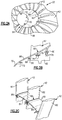
- the fan section 22 is shown in more detail in Figures 2A-2C .
- the fan section 22 includes multiple circumferentially arranged fan blades 42.
- Platforms 60, or spacers, are arranged between adjacent fan blades 42 and may be integral with or discrete from the fan blades 42.
- the fan blades 42 are mounted to a fan hub 62.
- a nose cone 64 is arranged forward of the fan blades 42 to provide an aerodynamic inner flowpath through the fan section 22 along with the platforms 60.
- the nose cone 64 is provided by a spinner 66 and a cap 70.
- the nose cone 66 is secured to the fan hub 62, via a lock ring 96 ( Figure 2B ), by fasteners 68.
- the cap 70 is secured to the spinner 66 by fasteners 72.
- a one-piece nose cone may also be used in which the cap 70 is integrated with the spinner 66.
- the platform 60 includes first and second flanges 74, 76 secured to corresponding attachment features on the fan hub 62 respectively by fasteners 78, 80.
- the fasteners 68, 72, 78, 80 are schematically depicted in Figures 2A and 2B by simple, thickened lines for clarity.
- the arrangement shown in Figure 2B is exemplary, and other platform configurations may be used, if desired.
- each fan blade 42 has an airfoil 82.
- Each platform 60 has an outer surface 84, which together form a ring with the other platforms 60, spaced about axis A to provide an aerodynamic inner flow path surface.
- a circumferential gap 86 exists between each platform outer surface 84 and an adjacent fan blade 42.
- Each gap 86 is blocked with a seal 88 to minimize a loss of airflow through the gas turbine engine 10.
- a single lock ring 96 is used to axially retain the fan blades to the fan hub 62.
- the spinner 66 is secured directly to the lock ring 96 using first and second fastening elements 100, 108.
- first and second fastening elements 100, 108 In the example shown, an integral flange 110 of the spinner 66 is secured to the lock ring 96.
- a separate bracket may be used if desired.
- Access to the second fastening element 108 is provided through a cavity 109 of the spinner 66 with the cap 70 (illustrated in Figure 2A ) removed.
- the fan hub 62 includes an annular recess 92 that receives the lock ring 96 in a locked position.
- An unlocked position is illustrated in Figure 4A .
- Circumferentially spaced apart hub tabs 94 are provided on the fan hub 62.
- circumferentially spaced ring tabs 98 are received in the gaps provided between the hub tabs 94 to permit the lock ring 96 to be slid into the annular recess 92.
- the lock ring 96 is rotated from this unlocked position to at least partially align the hub tabs 94 and the ring tabs 98, which prevents axial movement of the lock ring 96 with respect to the fan hub 62.
- a back side of the lock ring 96 abuts the roots 99 of the fan blades 42, as shown in Figure 4B .
- the first fastening element 100 which is a bolt in the example, extends through a hole 106 in the lock ring 96.
- a back side of the lock ring 96 includes a locating feature 104, such a notch, which cooperates with a head 102 of the first fastening element 100 to prevent rotation of the first fastening element 100 during tightening of the second fastening element 108.
- the flange 110 includes an inner diameter 124, which cooperates with an annular shoulder 122 of the fan hub 62 to precisely locate the spinner 66 relative to the fan hub on the common axis A.
- the spinner could be radially located with respect to the lock ring 96, if desired.
- a corresponding aperture 112 in the flange 110 receives the first fastening element 100.
- the flange 110 is secured to the first fastening element 100 by tightening of the second fastening element 108, which is a nut in the example.
- pins 118 are used to circumferentially lock the lock ring 96 with respect to the fan hub 62, as shown in Figure 6 .
- First and second slots 114, 116 which are arcuate in shape in one example, are respectively provided in the lock ring 96 and the fan hub 62 to receive discrete pins 118 in an interference fit relationship.
- the pins 118 prevent rotational movement of the lock ring 96 relative the fan hub 62.
- An end of each pin 120 is generally flush with respect to a front face of the lock ring 96, as best shown in Figure 7 .
- the flange 110 abuts the ends 120 to prevent the pins 118 from backing out of the first and second slots 114, 116.
Claims (15)
- Section de soufflante (22) pour un moteur à turbine à gaz comprenant :un moyeu de soufflante (62) muni de fentes de pales recevant une emplanture (99) d'une pale de soufflante (42) ;une bague de verrouillage (96) conçue pour se déplacer en rotation d'une position déverrouillée à une position verrouillée pour fixer l'emplanture de pale dans la fente de pale ; etun cône de nez (64), caractérisée en ce que le cône de nez (64) est fixé directement à la bague de verrouillage (96), ainsi fixée à la section de soufflante (22).
- Section de soufflante selon la revendication 1, dans laquelle le moyeu de soufflante (62) comporte des premières fentes (114) espacées de manière circonférentielle, la bague de verrouillage (96) comporte des secondes fentes (116) espacées de manière circonférentielle alignées avec les premières fentes (114) dans la position verrouillée, et dans laquelle la section de soufflante (22) comprend une pluralité d'éléments de positionnement distincts, chacun étant conçu pour être reçu de manière coulissante dans des premières et secondes fentes (114, 116) appariées dans la position verrouillée pour empêcher le mouvement de rotation de la bague de verrouillage (96) par rapport au moyeu de soufflante (62).
- Section de soufflante selon la revendication 2, dans laquelle les premières et secondes fentes (114, 116) sont de forme arquée, et chaque élément de positionnement comporte une broche (118) venant en prise avec les premières et secondes fentes (114, 116) dans un ajustement serré.
- Section de soufflante selon la revendication 3, dans laquelle la broche (118) comporte une extrémité retenue par le cône de nez (64).
- Section de soufflante selon une quelconque revendication précédente, comprenant des premier et second éléments de fixation (100, 108) coopérant l'un avec l'autre pour fixer le cône de nez (64) directement à la bague de verrouillage (96).
- Section de soufflante selon la revendication 5, dans laquelle le second élément de fixation (108) est un écrou fixé au premier élément de fixation (100).
- Section de soufflante selon la revendication 6, dans laquelle le premier élément de fixation (100) est monté dans la bague de verrouillage (96).
- Section de soufflante selon la revendication 7, dans laquelle le premier élément de fixation (100) comporte une tête (102) coopérant avec une caractéristique de positionnement (104) correspondante dans la bague de verrouillage (96) pour empêcher la rotation du premier élément de fixation (100).
- Section de soufflante selon la revendication 8, dans laquelle la caractéristique de positionnement (104) correspondante est une encoche dans un côté arrière de la bague de verrouillage (96).
- Section de soufflante selon une quelconque revendication précédente, dans laquelle le moyeu de soufflante (62) fournit un épaulement, et le cône de nez (64) comporte une bride (110) présentant un diamètre interne situé radialement par rapport à l'épaulement pour aligner concentriquement le cône de nez (64) avec le moyeu de soufflante (62).
- Section de soufflante selon la revendication 10, dans laquelle le cône de nez (64) comporte une casserole d'hélice (66) qui fournit la bride, et un capuchon (70) fixé à la casserole d'hélice (66) pour enfermer une cavité de la casserole d'hélice (66).
- Procédé d'assemblage d'une section de soufflante (22) du moteur à turbine à gaz, comprenant les étapes de :montage de pales de soufflante (42) dans un moyeu de soufflante (62) ;coulissement d'une bague de verrouillage (96) sur le moyeu de soufflante (62) ; etrotation de la bague de verrouillage (96) pour retenir axialement les pales de soufflante (42) à l'intérieur du moyeu de soufflante (62), caractérisé par la fixation d'un cône de nez (64) directement à la bague de verrouillage (96).
- Procédé selon la revendication 12, dans lequel l'étape de montage comporte le coulissement d'emplantures des pales de soufflante (42) dans les fentes correspondantes du moyeu de soufflante (62), moyennant quoi la bague de verrouillage (96) bloque axialement le déplacement axial des emplantures de pale de soufflante, et/ou comprenant l'étape d'insertion des premiers éléments de fixation (100) dans la bague de verrouillage (96) avant de faire coulisser la bague de verrouillage (96) sur le moyeu de soufflante (62).
- Procédé selon la revendication 12 ou 13, comprenant l'étape d'insertion d'éléments de positionnement (118) distincts dans des fentes alignées dans le moyeu de soufflante (62) et une bague de verrouillage (96) pour empêcher le mouvement de rotation relatif entre la bague de verrouillage (96) et un moyeu de soufflante (62) avant l'étape de fixation.
- Procédé selon la revendication 12, 13 ou 14, dans lequel l'étape de fixation comporte la fixation d'une casserole d'hélice (66) à la bague de verrouillage (96), et la fixation d'un capuchon (70) à la casserole d'hélice (66).
Applications Claiming Priority (2)
| Application Number | Priority Date | Filing Date | Title |
|---|---|---|---|
| US201361773687P | 2013-03-06 | 2013-03-06 | |
| PCT/US2014/018567 WO2014137688A1 (fr) | 2013-03-06 | 2014-02-26 | Fixation de cône de nez de turbine à gaz |
Publications (3)
| Publication Number | Publication Date |
|---|---|
| EP2964522A1 EP2964522A1 (fr) | 2016-01-13 |
| EP2964522A4 EP2964522A4 (fr) | 2016-10-19 |
| EP2964522B1 true EP2964522B1 (fr) | 2021-06-16 |
Family
ID=51491789
Family Applications (1)
| Application Number | Title | Priority Date | Filing Date |
|---|---|---|---|
| EP14760886.3A Active EP2964522B1 (fr) | 2013-03-06 | 2014-02-26 | Fixation de cône de nez de turbine à gaz |
Country Status (3)
| Country | Link |
|---|---|
| US (1) | US10072509B2 (fr) |
| EP (1) | EP2964522B1 (fr) |
| WO (1) | WO2014137688A1 (fr) |
Families Citing this family (5)
| Publication number | Priority date | Publication date | Assignee | Title |
|---|---|---|---|---|
| US10343765B2 (en) * | 2016-06-02 | 2019-07-09 | United Technologies Corporation | Toroidal spinner aft flange |
| US20190063452A1 (en) * | 2017-08-29 | 2019-02-28 | United Technologies Corporation | Conical fan hub and method for reducing blade off loads |
| US11028714B2 (en) * | 2018-07-16 | 2021-06-08 | Raytheon Technologies Corporation | Fan platform wedge seal |
| US10823151B2 (en) * | 2018-10-05 | 2020-11-03 | Hamilton Sunstrand Corporation | Ram air turbine single-unit nose mass |
| PL431184A1 (pl) * | 2019-09-17 | 2021-03-22 | General Electric Company Polska Spółka Z Ograniczoną Odpowiedzialnością | Zespół silnika turbinowego |
Family Cites Families (23)
| Publication number | Priority date | Publication date | Assignee | Title |
|---|---|---|---|---|
| US6457942B1 (en) | 2000-11-27 | 2002-10-01 | General Electric Company | Fan blade retainer |
| US6481971B1 (en) | 2000-11-27 | 2002-11-19 | General Electric Company | Blade spacer |
| US6951448B2 (en) | 2002-04-16 | 2005-10-04 | United Technologies Corporation | Axial retention system and components thereof for a bladed rotor |
| US6739837B2 (en) * | 2002-04-16 | 2004-05-25 | United Technologies Corporation | Bladed rotor with a tiered blade to hub interface |
| US6846159B2 (en) | 2002-04-16 | 2005-01-25 | United Technologies Corporation | Chamfered attachment for a bladed rotor |
| US6887043B2 (en) | 2003-03-28 | 2005-05-03 | General Electric Company | Methods and apparatus for assembling gas turbine engines |
| FR2888897B1 (fr) * | 2005-07-21 | 2007-10-19 | Snecma | Dispositif d'amortissement des vibrations d'un anneau de retention axiale des aubes de soufflante d'une turbomachine |
| FR2889264B1 (fr) | 2005-07-29 | 2007-11-02 | Snecma | Verrouillage des aubes dans un rotor de soufflante |
| FR2913048B1 (fr) | 2007-02-28 | 2009-04-10 | Snecma Sa | Soufflante de turbomachine |
| GB0803366D0 (en) | 2008-02-26 | 2008-04-02 | Rolls Royce Plc | Nose cone assembly |
| GB2468834B (en) | 2008-12-22 | 2011-02-09 | Rolls Royce Plc | A composite component |
| US8616854B2 (en) * | 2009-03-05 | 2013-12-31 | Rolls-Royce Corporation | Nose cone assembly |
| US8419370B2 (en) * | 2009-06-25 | 2013-04-16 | Rolls-Royce Corporation | Retaining and sealing ring assembly |
| KR101633459B1 (ko) | 2009-08-10 | 2016-06-24 | 삼성전자주식회사 | 컬러 간의 상관 관계를 이용한 영상 데이터 인코딩 장치 및 방법, 그리고 영상 데이터 디코딩 장치 및 방법 |
| US8469670B2 (en) | 2009-08-27 | 2013-06-25 | Rolls-Royce Corporation | Fan assembly |
| US8459954B2 (en) * | 2010-01-19 | 2013-06-11 | United Technologies Corporation | Torsional flexing energy absorbing blade lock |
| JP2011159853A (ja) | 2010-02-02 | 2011-08-18 | Toshiba Corp | 半導体装置およびその製造方法 |
| GB2490858B (en) * | 2011-03-22 | 2014-01-01 | Rolls Royce Plc | A bladed rotor |
| GB201111666D0 (en) * | 2011-07-08 | 2011-08-24 | Rolls Royce Plc | A joint assembly for an annular structure |
| US10024177B2 (en) * | 2012-05-15 | 2018-07-17 | United Technologies Corporation | Detachable fan blade platform and method of repairing same |
| US9017033B2 (en) * | 2012-06-07 | 2015-04-28 | United Technologies Corporation | Fan blade platform |
| US9376926B2 (en) * | 2012-11-15 | 2016-06-28 | United Technologies Corporation | Gas turbine engine fan blade lock assembly |
| US9650902B2 (en) * | 2013-01-11 | 2017-05-16 | United Technologies Corporation | Integral fan blade wear pad and platform seal |
-
2014
- 2014-02-26 US US14/768,228 patent/US10072509B2/en active Active
- 2014-02-26 WO PCT/US2014/018567 patent/WO2014137688A1/fr active Application Filing
- 2014-02-26 EP EP14760886.3A patent/EP2964522B1/fr active Active
Non-Patent Citations (1)
| Title |
|---|
| None * |
Also Published As
| Publication number | Publication date |
|---|---|
| EP2964522A4 (fr) | 2016-10-19 |
| WO2014137688A1 (fr) | 2014-09-12 |
| US20150361804A1 (en) | 2015-12-17 |
| US10072509B2 (en) | 2018-09-11 |
| EP2964522A1 (fr) | 2016-01-13 |
Similar Documents
| Publication | Publication Date | Title |
|---|---|---|
| US9376926B2 (en) | Gas turbine engine fan blade lock assembly | |
| EP2885507B1 (fr) | Joint étanche à l'air intérieur à bague entièrement filetée | |
| EP2971673B1 (fr) | Pressurisation d'une roue de turbine d'un moteur à turbine à gaz | |
| EP2964522B1 (fr) | Fixation de cône de nez de turbine à gaz | |
| US9650905B2 (en) | Singlet vane cluster assembly | |
| EP2880282B1 (fr) | Ensemble compresseur avec ergot anti-rotation de stator | |
| US10119423B2 (en) | Gas turbine engine fan spacer platform attachments | |
| US9790803B2 (en) | Double split blade lock ring | |
| EP3051067A1 (fr) | Entrée aérodynamique tronquée de moteur à turbine à gaz | |
| EP2943658B1 (fr) | Dispositif anti-rotation de stator | |
| EP3228856B1 (fr) | Élément de retrait de pale de soufflante pour moteur à turbine à gaz et méthode associée | |
| US20140161616A1 (en) | Multi-piece blade for gas turbine engine | |
| EP3404215B1 (fr) | Moteur de turbine à gaz avec fixation anti-rotation de joint d'étanchéité | |
| EP3045658B1 (fr) | Rotor de moteur de turbine à gaz | |
| US10724384B2 (en) | Intermittent tab configuration for retaining ring retention |
Legal Events
| Date | Code | Title | Description |
|---|---|---|---|
| PUAI | Public reference made under article 153(3) epc to a published international application that has entered the european phase |
Free format text: ORIGINAL CODE: 0009012 |
|
| 17P | Request for examination filed |
Effective date: 20151005 |
|
| AK | Designated contracting states |
Kind code of ref document: A1 Designated state(s): AL AT BE BG CH CY CZ DE DK EE ES FI FR GB GR HR HU IE IS IT LI LT LU LV MC MK MT NL NO PL PT RO RS SE SI SK SM TR |
|
| AX | Request for extension of the european patent |
Extension state: BA ME |
|
| DAX | Request for extension of the european patent (deleted) | ||
| A4 | Supplementary search report drawn up and despatched |
Effective date: 20160920 |
|
| RIC1 | Information provided on ipc code assigned before grant |
Ipc: F01D 5/32 20060101ALI20160914BHEP Ipc: F01D 5/12 20060101ALI20160914BHEP Ipc: F01D 5/30 20060101ALI20160914BHEP Ipc: F02K 3/06 20060101ALI20160914BHEP Ipc: F02C 7/04 20060101ALI20160914BHEP Ipc: F01D 9/04 20060101ALI20160914BHEP Ipc: F01D 5/02 20060101ALI20160914BHEP Ipc: F01D 5/06 20060101ALI20160914BHEP Ipc: B64C 11/14 20060101AFI20160914BHEP |
|
| RAP1 | Party data changed (applicant data changed or rights of an application transferred) |
Owner name: UNITED TECHNOLOGIES CORPORATION |
|
| STAA | Information on the status of an ep patent application or granted ep patent |
Free format text: STATUS: EXAMINATION IS IN PROGRESS |
|
| 17Q | First examination report despatched |
Effective date: 20181109 |
|
| GRAP | Despatch of communication of intention to grant a patent |
Free format text: ORIGINAL CODE: EPIDOSNIGR1 |
|
| STAA | Information on the status of an ep patent application or granted ep patent |
Free format text: STATUS: GRANT OF PATENT IS INTENDED |
|
| INTG | Intention to grant announced |
Effective date: 20210115 |
|
| RAP1 | Party data changed (applicant data changed or rights of an application transferred) |
Owner name: RAYTHEON TECHNOLOGIES CORPORATION |
|
| GRAS | Grant fee paid |
Free format text: ORIGINAL CODE: EPIDOSNIGR3 |
|
| GRAA | (expected) grant |
Free format text: ORIGINAL CODE: 0009210 |
|
| STAA | Information on the status of an ep patent application or granted ep patent |
Free format text: STATUS: THE PATENT HAS BEEN GRANTED |
|
| AK | Designated contracting states |
Kind code of ref document: B1 Designated state(s): AL AT BE BG CH CY CZ DE DK EE ES FI FR GB GR HR HU IE IS IT LI LT LU LV MC MK MT NL NO PL PT RO RS SE SI SK SM TR |
|
| REG | Reference to a national code |
Ref country code: GB Ref legal event code: FG4D |
|
| REG | Reference to a national code |
Ref country code: CH Ref legal event code: EP |
|
| REG | Reference to a national code |
Ref country code: DE Ref legal event code: R096 Ref document number: 602014078147 Country of ref document: DE |
|
| REG | Reference to a national code |
Ref country code: AT Ref legal event code: REF Ref document number: 1402136 Country of ref document: AT Kind code of ref document: T Effective date: 20210715 |
|
| REG | Reference to a national code |
Ref country code: IE Ref legal event code: FG4D |
|
| REG | Reference to a national code |
Ref country code: LT Ref legal event code: MG9D |
|
| PG25 | Lapsed in a contracting state [announced via postgrant information from national office to epo] |
Ref country code: HR Free format text: LAPSE BECAUSE OF FAILURE TO SUBMIT A TRANSLATION OF THE DESCRIPTION OR TO PAY THE FEE WITHIN THE PRESCRIBED TIME-LIMIT Effective date: 20210616 Ref country code: LT Free format text: LAPSE BECAUSE OF FAILURE TO SUBMIT A TRANSLATION OF THE DESCRIPTION OR TO PAY THE FEE WITHIN THE PRESCRIBED TIME-LIMIT Effective date: 20210616 Ref country code: FI Free format text: LAPSE BECAUSE OF FAILURE TO SUBMIT A TRANSLATION OF THE DESCRIPTION OR TO PAY THE FEE WITHIN THE PRESCRIBED TIME-LIMIT Effective date: 20210616 Ref country code: BG Free format text: LAPSE BECAUSE OF FAILURE TO SUBMIT A TRANSLATION OF THE DESCRIPTION OR TO PAY THE FEE WITHIN THE PRESCRIBED TIME-LIMIT Effective date: 20210916 |
|
| REG | Reference to a national code |
Ref country code: AT Ref legal event code: MK05 Ref document number: 1402136 Country of ref document: AT Kind code of ref document: T Effective date: 20210616 |
|
| REG | Reference to a national code |
Ref country code: NL Ref legal event code: MP Effective date: 20210616 |
|
| PG25 | Lapsed in a contracting state [announced via postgrant information from national office to epo] |
Ref country code: RS Free format text: LAPSE BECAUSE OF FAILURE TO SUBMIT A TRANSLATION OF THE DESCRIPTION OR TO PAY THE FEE WITHIN THE PRESCRIBED TIME-LIMIT Effective date: 20210616 Ref country code: SE Free format text: LAPSE BECAUSE OF FAILURE TO SUBMIT A TRANSLATION OF THE DESCRIPTION OR TO PAY THE FEE WITHIN THE PRESCRIBED TIME-LIMIT Effective date: 20210616 Ref country code: NO Free format text: LAPSE BECAUSE OF FAILURE TO SUBMIT A TRANSLATION OF THE DESCRIPTION OR TO PAY THE FEE WITHIN THE PRESCRIBED TIME-LIMIT Effective date: 20210916 Ref country code: LV Free format text: LAPSE BECAUSE OF FAILURE TO SUBMIT A TRANSLATION OF THE DESCRIPTION OR TO PAY THE FEE WITHIN THE PRESCRIBED TIME-LIMIT Effective date: 20210616 Ref country code: GR Free format text: LAPSE BECAUSE OF FAILURE TO SUBMIT A TRANSLATION OF THE DESCRIPTION OR TO PAY THE FEE WITHIN THE PRESCRIBED TIME-LIMIT Effective date: 20210917 |
|
| PG25 | Lapsed in a contracting state [announced via postgrant information from national office to epo] |
Ref country code: AT Free format text: LAPSE BECAUSE OF FAILURE TO SUBMIT A TRANSLATION OF THE DESCRIPTION OR TO PAY THE FEE WITHIN THE PRESCRIBED TIME-LIMIT Effective date: 20210616 Ref country code: ES Free format text: LAPSE BECAUSE OF FAILURE TO SUBMIT A TRANSLATION OF THE DESCRIPTION OR TO PAY THE FEE WITHIN THE PRESCRIBED TIME-LIMIT Effective date: 20210616 Ref country code: NL Free format text: LAPSE BECAUSE OF FAILURE TO SUBMIT A TRANSLATION OF THE DESCRIPTION OR TO PAY THE FEE WITHIN THE PRESCRIBED TIME-LIMIT Effective date: 20210616 Ref country code: PT Free format text: LAPSE BECAUSE OF FAILURE TO SUBMIT A TRANSLATION OF THE DESCRIPTION OR TO PAY THE FEE WITHIN THE PRESCRIBED TIME-LIMIT Effective date: 20211018 Ref country code: RO Free format text: LAPSE BECAUSE OF FAILURE TO SUBMIT A TRANSLATION OF THE DESCRIPTION OR TO PAY THE FEE WITHIN THE PRESCRIBED TIME-LIMIT Effective date: 20210616 Ref country code: CZ Free format text: LAPSE BECAUSE OF FAILURE TO SUBMIT A TRANSLATION OF THE DESCRIPTION OR TO PAY THE FEE WITHIN THE PRESCRIBED TIME-LIMIT Effective date: 20210616 Ref country code: EE Free format text: LAPSE BECAUSE OF FAILURE TO SUBMIT A TRANSLATION OF THE DESCRIPTION OR TO PAY THE FEE WITHIN THE PRESCRIBED TIME-LIMIT Effective date: 20210616 Ref country code: SM Free format text: LAPSE BECAUSE OF FAILURE TO SUBMIT A TRANSLATION OF THE DESCRIPTION OR TO PAY THE FEE WITHIN THE PRESCRIBED TIME-LIMIT Effective date: 20210616 Ref country code: SK Free format text: LAPSE BECAUSE OF FAILURE TO SUBMIT A TRANSLATION OF THE DESCRIPTION OR TO PAY THE FEE WITHIN THE PRESCRIBED TIME-LIMIT Effective date: 20210616 |
|
| PG25 | Lapsed in a contracting state [announced via postgrant information from national office to epo] |
Ref country code: PL Free format text: LAPSE BECAUSE OF FAILURE TO SUBMIT A TRANSLATION OF THE DESCRIPTION OR TO PAY THE FEE WITHIN THE PRESCRIBED TIME-LIMIT Effective date: 20210616 |
|
| REG | Reference to a national code |
Ref country code: DE Ref legal event code: R097 Ref document number: 602014078147 Country of ref document: DE |
|
| PLBE | No opposition filed within time limit |
Free format text: ORIGINAL CODE: 0009261 |
|
| STAA | Information on the status of an ep patent application or granted ep patent |
Free format text: STATUS: NO OPPOSITION FILED WITHIN TIME LIMIT |
|
| PG25 | Lapsed in a contracting state [announced via postgrant information from national office to epo] |
Ref country code: DK Free format text: LAPSE BECAUSE OF FAILURE TO SUBMIT A TRANSLATION OF THE DESCRIPTION OR TO PAY THE FEE WITHIN THE PRESCRIBED TIME-LIMIT Effective date: 20210616 |
|
| 26N | No opposition filed |
Effective date: 20220317 |
|
| PG25 | Lapsed in a contracting state [announced via postgrant information from national office to epo] |
Ref country code: AL Free format text: LAPSE BECAUSE OF FAILURE TO SUBMIT A TRANSLATION OF THE DESCRIPTION OR TO PAY THE FEE WITHIN THE PRESCRIBED TIME-LIMIT Effective date: 20210616 |
|
| PG25 | Lapsed in a contracting state [announced via postgrant information from national office to epo] |
Ref country code: IT Free format text: LAPSE BECAUSE OF FAILURE TO SUBMIT A TRANSLATION OF THE DESCRIPTION OR TO PAY THE FEE WITHIN THE PRESCRIBED TIME-LIMIT Effective date: 20210616 |
|
| PG25 | Lapsed in a contracting state [announced via postgrant information from national office to epo] |
Ref country code: MC Free format text: LAPSE BECAUSE OF FAILURE TO SUBMIT A TRANSLATION OF THE DESCRIPTION OR TO PAY THE FEE WITHIN THE PRESCRIBED TIME-LIMIT Effective date: 20210616 |
|
| REG | Reference to a national code |
Ref country code: CH Ref legal event code: PL |
|
| REG | Reference to a national code |
Ref country code: BE Ref legal event code: MM Effective date: 20220228 |
|
| PG25 | Lapsed in a contracting state [announced via postgrant information from national office to epo] |
Ref country code: LU Free format text: LAPSE BECAUSE OF NON-PAYMENT OF DUE FEES Effective date: 20220226 |
|
| PG25 | Lapsed in a contracting state [announced via postgrant information from national office to epo] |
Ref country code: LI Free format text: LAPSE BECAUSE OF NON-PAYMENT OF DUE FEES Effective date: 20220228 Ref country code: IE Free format text: LAPSE BECAUSE OF NON-PAYMENT OF DUE FEES Effective date: 20220226 Ref country code: CH Free format text: LAPSE BECAUSE OF NON-PAYMENT OF DUE FEES Effective date: 20220228 |
|
| PG25 | Lapsed in a contracting state [announced via postgrant information from national office to epo] |
Ref country code: BE Free format text: LAPSE BECAUSE OF NON-PAYMENT OF DUE FEES Effective date: 20220228 |
|
| PGFP | Annual fee paid to national office [announced via postgrant information from national office to epo] |
Ref country code: FR Payment date: 20230119 Year of fee payment: 10 |
|
| PGFP | Annual fee paid to national office [announced via postgrant information from national office to epo] |
Ref country code: GB Payment date: 20230121 Year of fee payment: 10 Ref country code: DE Payment date: 20230119 Year of fee payment: 10 |
|
| P01 | Opt-out of the competence of the unified patent court (upc) registered |
Effective date: 20230520 |
|
| PG25 | Lapsed in a contracting state [announced via postgrant information from national office to epo] |
Ref country code: HU Free format text: LAPSE BECAUSE OF FAILURE TO SUBMIT A TRANSLATION OF THE DESCRIPTION OR TO PAY THE FEE WITHIN THE PRESCRIBED TIME-LIMIT; INVALID AB INITIO Effective date: 20140226 |
|
| PG25 | Lapsed in a contracting state [announced via postgrant information from national office to epo] |
Ref country code: MK Free format text: LAPSE BECAUSE OF FAILURE TO SUBMIT A TRANSLATION OF THE DESCRIPTION OR TO PAY THE FEE WITHIN THE PRESCRIBED TIME-LIMIT Effective date: 20210616 Ref country code: CY Free format text: LAPSE BECAUSE OF FAILURE TO SUBMIT A TRANSLATION OF THE DESCRIPTION OR TO PAY THE FEE WITHIN THE PRESCRIBED TIME-LIMIT Effective date: 20210616 |
|
| PGFP | Annual fee paid to national office [announced via postgrant information from national office to epo] |
Ref country code: DE Payment date: 20240123 Year of fee payment: 11 Ref country code: GB Payment date: 20240123 Year of fee payment: 11 |