EP2964121B1 - Intramedulläre vorrichtung und verfahren zur behandlung von knochenbrüchen damit - Google Patents
Intramedulläre vorrichtung und verfahren zur behandlung von knochenbrüchen damit Download PDFInfo
- Publication number
- EP2964121B1 EP2964121B1 EP14760471.4A EP14760471A EP2964121B1 EP 2964121 B1 EP2964121 B1 EP 2964121B1 EP 14760471 A EP14760471 A EP 14760471A EP 2964121 B1 EP2964121 B1 EP 2964121B1
- Authority
- EP
- European Patent Office
- Prior art keywords
- nail
- bone
- locking
- bone fragment
- locking holes
- Prior art date
- Legal status (The legal status is an assumption and is not a legal conclusion. Google has not performed a legal analysis and makes no representation as to the accuracy of the status listed.)
- Not-in-force
Links
- 208000010392 Bone Fractures Diseases 0.000 title description 21
- 238000000034 method Methods 0.000 title description 17
- 210000000988 bone and bone Anatomy 0.000 claims description 228
- 239000012634 fragment Substances 0.000 claims description 171
- 241001465754 Metazoa Species 0.000 claims description 11
- 239000000463 material Substances 0.000 claims description 6
- 239000002184 metal Substances 0.000 claims description 6
- 238000005553 drilling Methods 0.000 description 3
- 238000005728 strengthening Methods 0.000 description 2
- 241000282472 Canis lupus familiaris Species 0.000 description 1
- 241000282326 Felis catus Species 0.000 description 1
- 241000282414 Homo sapiens Species 0.000 description 1
- 241000124008 Mammalia Species 0.000 description 1
- 241000251539 Vertebrata <Metazoa> Species 0.000 description 1
- 230000007812 deficiency Effects 0.000 description 1
- 230000001066 destructive effect Effects 0.000 description 1
- 238000012986 modification Methods 0.000 description 1
- 230000004048 modification Effects 0.000 description 1
- 238000011282 treatment Methods 0.000 description 1
Images








Classifications
-
- A—HUMAN NECESSITIES
- A61—MEDICAL OR VETERINARY SCIENCE; HYGIENE
- A61B—DIAGNOSIS; SURGERY; IDENTIFICATION
- A61B17/00—Surgical instruments, devices or methods
- A61B17/56—Surgical instruments or methods for treatment of bones or joints; Devices specially adapted therefor
- A61B17/58—Surgical instruments or methods for treatment of bones or joints; Devices specially adapted therefor for osteosynthesis, e.g. bone plates, screws or setting implements
- A61B17/68—Internal fixation devices, including fasteners and spinal fixators, even if a part thereof projects from the skin
- A61B17/72—Intramedullary devices, e.g. pins or nails
- A61B17/7233—Intramedullary devices, e.g. pins or nails with special means of locking the nail to the bone
-
- A—HUMAN NECESSITIES
- A61—MEDICAL OR VETERINARY SCIENCE; HYGIENE
- A61B—DIAGNOSIS; SURGERY; IDENTIFICATION
- A61B17/00—Surgical instruments, devices or methods
- A61B17/16—Instruments for performing osteoclasis; Drills or chisels for bones; Trepans
- A61B17/17—Guides or aligning means for drills, mills, pins or wires
- A61B17/1725—Guides or aligning means for drills, mills, pins or wires for applying transverse screws or pins through intramedullary nails or pins
-
- A—HUMAN NECESSITIES
- A61—MEDICAL OR VETERINARY SCIENCE; HYGIENE
- A61B—DIAGNOSIS; SURGERY; IDENTIFICATION
- A61B90/00—Instruments, implements or accessories specially adapted for surgery or diagnosis and not covered by any of the groups A61B1/00 - A61B50/00, e.g. for luxation treatment or for protecting wound edges
- A61B90/39—Markers, e.g. radio-opaque or breast lesions markers
-
- A—HUMAN NECESSITIES
- A61—MEDICAL OR VETERINARY SCIENCE; HYGIENE
- A61B—DIAGNOSIS; SURGERY; IDENTIFICATION
- A61B17/00—Surgical instruments, devices or methods
- A61B17/56—Surgical instruments or methods for treatment of bones or joints; Devices specially adapted therefor
- A61B17/58—Surgical instruments or methods for treatment of bones or joints; Devices specially adapted therefor for osteosynthesis, e.g. bone plates, screws or setting implements
- A61B17/68—Internal fixation devices, including fasteners and spinal fixators, even if a part thereof projects from the skin
- A61B17/72—Intramedullary devices, e.g. pins or nails
-
- A—HUMAN NECESSITIES
- A61—MEDICAL OR VETERINARY SCIENCE; HYGIENE
- A61B—DIAGNOSIS; SURGERY; IDENTIFICATION
- A61B17/00—Surgical instruments, devices or methods
- A61B17/56—Surgical instruments or methods for treatment of bones or joints; Devices specially adapted therefor
- A61B2017/564—Methods for bone or joint treatment
Definitions
- the present disclosure generally relates to bone fracture treatments, and more particularly to an intramedullary (IM) apparatus and methods of treating bone fracture using the same.
- IM intramedullary
- An intramedullary (IM) nail also known as an IM rod or inter-locking nail, is a rigid rod long used to treat fractures of bones of the body.
- an IM nail may be inserted (in some occasions forced) into the medullary cavity of the fractured bone to fix and maintain relative positional stability of the fractured bone parts.
- IM nails are particularly useful in treating fractures of long bones of the body.
- a long bone has two joint ends connected to the joints.
- each bone fragment would have a fractured end corresponding to each other, and at least one of the bone fragment is deviated from its original position due to the fracture in most cases.
- an IM nail may be inserted into the medullary cavity of the fractured long bone to fix the two bone fragments.
- the IM nail is inserted to the medullary cavity of one bone fragment from the fractured end.
- the bone fragment can be forced back to its original position corresponding to the other bone fragment, and the IM nail can be pushed toward the medullary cavity of the other bone fragment such that the IM nail is located to be disposed between the fractured ends of the two bone fragments.
- the bone fragments can be fixed to the IM nail by a plurality of locking members, such as screws or pins.
- the IM nail may be fixed to the two bone fragments at the end of the comminuted long bone, and then the other bone fragments between these two bone fragments at the end may be disposed and fixed on the IM nail.
- the IM nail may have a plurality of locking holes, such as screw holes and pin holes, such that the locking member (for example, a screw or a pin) may be used to lock the bone fragment to the IM nail.
- Fixing of the bone fragment to the IM nail may be done by drilling a hole on the bone fragment corresponding to the position of one of the locking holes of the IM nail such that the locking member may be inserted to the locking hole through the hole on the bone fragment.
- the fixing is generally difficult because the locking holes of the IM nail are hidden in the medullary cavity of the bone fragment and are difficult to locate.
- the length of the IM nail must be longer than the length of the bone fragment such that there will be an exposed part of the IM nail for the doctor to hold and locate the position of the IM nail within the medullary cavity of the bone fragment.
- the IM nail must be forced to pass through the joint end of the bone fragment such that, when the bone fragment to be forced back to its original position corresponding to the other bone fragment, the doctor may push the exposed IM nail part from the joint end toward the medullary cavity of the other bone fragment. In this way, the pass-through of the IM nail may be destructive to the joint.
- Publication US 2004/0215204 A1 discloses an apparatus in which locking holes are provided both perpendicular to the longitudinal axis in a vertical direction and perpendicular to the longitudinal axis in a horizontal direction.
- the present disclosure in one aspect, relates to an intramedullary (IM) apparatus for treating a fractured bone of an animal.
- the IM apparatus includes an IM nail elongated along a longitudinal axis and having at least three locking holes equally distantly defined thereon along the longitudinal axis, and a positional reference member having a longitudinal vernier scale thereon.
- the IM nail is configured to be inserted to a medullary cavity of a bone fragment of the fractured bone, such that the IM nail is fixable to the bone fragment by a locking member correspondingly inserted into one of the locking holes through the bone fragment.
- the positional reference member is configured to be detachably mounted to the IM nail by two positioning members inserted into two of the locking holes such that the longitudinal vernier scale is parallel to the longitudinal axis of the IM nail, and each of the locking holes is locatable by the longitudinal vernier scale.
- the IM apparatus further includes a plate configured to be positioned outside the bone fragment and detachably fixed to the bone fragment and the IM nail by the locking member.
- the locking holes are through-holes substantially perpendicular to the longitudinal axis.
- the locking holes include at least one vertical locking hole perpendicular to the longitudinal axis in a vertical direction, and at least one horizontal locking hole perpendicular to the longitudinal axis in a horizontal direction
- the positional reference member has a plurality of mounting holes corresponding to the two positioning members.
- the locking member and the positioning members are screws, and the locking holes are screw holes corresponding to the screws.
- the IM nail is made of a metal or dissolvable artificial skeletal material.
- Another aspect of the present disclosure relates to a method of fixing an intramedullary (IM) apparatus to a bone fragment of a fractured bone of an animal, the method comprising: inserting an IM nail into a medullary cavity of the bone fragment, wherein the IM nail is elongated along a longitudinal axis and has at least three locking holes equally distantly defined thereon along the longitudinal axis, such that at least one of the locking holes is hidden by the bone fragment and at least two of the locking holes are exposed from the bone fragment; mounting a positional reference member to the IM nail by two positioning members inserted into the at least two exposed locking holes, such that a longitudinal vernier scale on the positional reference member is parallel to the longitudinal axis of the IM nail; locating the at least one hidden locking hole in the bone fragment by the longitudinal vernier scale of the positional reference member; and fixing the IM nail to the bone fragment by inserting a locking member to the located hidden locking hole through the bone fragment.
- IM intramedullary
- the method further includes: drilling a hole on the bone fragment corresponding to the located hidden locking hole such that the IM nail is fixable to the bone fragment by inserting the locking member through the hole to the located hidden locking hole.
- the locking member and the positioning members are screws, and the locking holes are screw holes corresponding to the screws.
- the IM nail is made of a metal or dissolvable artificial skeletal material.
- a method of treating a fractured bone of an animal using an intramedullary (IM) apparatus includes: inserting an IM nail into a medullary cavity of a first bone fragment of the fractured bone from a fracture end of the first bone fragment, wherein the IM nail is elongated along a longitudinal axis and has a plurality of locking holes positioned along the longitudinal axis, such that the locking holes are hidden in the first bone fragment, and an exposed part of the IM nail from the fracture end of the first bone fragment has at least two of the locking holes; cutting a slot along the longitudinal axis on the first bone fragment, such that at least two of the hidden locking holes in the first bone fragment is exposed through the slot; mounting a positional reference member to the IM nail by two positioning members inserted into the at least two exposed locking holes through the slot, such that a longitudinal vernier scale on the positional reference member is parallel to the longitudinal axis of the IM nail; inserting the exposed part of the IM nail into a medullary cavity
- the method further includes: removing the positional reference member, and fixing the IM nail to the first bone fragment by the positioning members to the at least two exposed locking holes through the slot.
- the method further includes: moving the IM nail in the first bone fragment towards the second bone fragment by pushing the positioning members along the slot towards the fractured end of the first bone fragment.
- the method further includes: drilling a hole on the second bone fragment corresponding to the located hidden locking hole such that the IM nail is fixable to the second bone fragment by inserting the locking member through the hole to the located hidden locking hole.
- the locking member and the positioning members are screws, and the locking holes are screw holes corresponding to the screws.
- the IM nail is made of a metal or dissolvable artificial skeletal material.
- Another aspect of the present disclosure relates to a method of treating a comminuted fractured bone of an animal using an intramedullary (IM) apparatus.
- the method includes: inserting an IM nail into a medullary cavity of a first bone fragment of the fractured bone from a fracture end of the first bone fragment, wherein the IM nail is elongated along a longitudinal axis and has at least four of locking holes positioned along the longitudinal axis, such that at least one of the locking holes is hidden in the first bone fragment, and an exposed part of the IM nail from the fracture end of the first bone fragment has at least three of the locking holes; inserting the exposed part of the IM nail into a medullary cavity of a second bone fragment of the fractured bone from a fracture end of the second bone fragment such that the at least one of the locking holes on the exposed part of the IM nail is hidden in the second bone fragment, and at least two of the locking holes are exposed; mounting a positional reference member to the IM nail by two positioning members inserted
- fixing the third bone fragments further includes: removing the positional reference member and the two positioning members; disposing the third bone fragments of the fractured bone on the IM nail, wherein each of the third bone fragments correspond to the at least one of the at least two exposed locking holes; and fixing each of the third bone fragments to the IM nail by inserting the locking members to the at least two exposed locking holes through the third bone fragments, respectively.
- the locking member and the positioning members are screws, and the locking holes are screw holes corresponding to the screws.
- the IM nail is made of a metal or dissolvable artificial skeletal material.
- first, second, third etc. may be used herein to describe various elements, components, regions, layers and/or sections, these elements, components, regions, layers, segments and/or sections should not be limited by these terms. These terms are only used to distinguish one element, component, region, layer, segment or section from another element, component, region, layer, segment or section. Thus, a first element, component, region, layer, segment or section discussed below could be termed a second element, component, region, layer, segment or section without departing from the teachings of the present disclosure.
- relative terms such as “lower” or “bottom” and “upper” or “top”, may be used herein to describe one element's relationship to another element as illustrated in the Figures. It will be understood that relative terms are intended to encompass different orientations of the device in addition to the orientation depicted in the Figures. For example, if the device in one of the figures is turned over, elements described as being on the “lower” side of other elements would then be oriented on “upper” sides of the other elements. The exemplary term “lower”, can therefore, encompasses both an orientation of “lower” and “upper”, depending of the particular orientation of the figure.
- this disclosure in one aspect, relates to an IM apparatus and methods of treating bone fractures using the same.
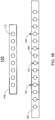
- FIGs 1A and 1B show schematically an IM apparatus according to one embodiment of the present disclosure, where FIG. 1A shows a plain view and FIG. 1B shows a top view.
- the IM apparatus 100 includes an IM nail 110 and a positional reference member 120, which may be used for treating a fractured bone of an animal. Further, a plurality of positioning members 132 and locking members 134 are provided for positioning and locking of the IM nail 110.
- the locking members 134 and the positioning members 132 are screws, pins or other fixing or locking structure or device.
- the IM nail 110 is elongated along a longitudinal axis, i.e. the horizontal direction as shown in FIGs. 1A and 1B , and has a plurality of locking holes 112 equally distantly defined thereon along the longitudinal axis. As shown in FIGs. 1A and 1B , the IM nail 110 has eight locking holes 112. In certain embodiments, the IM nail 110 may have at least three locking holes 112. The locking holes 112 may be through-holes substantially perpendicular to the longitudinal axis of the IM nail 110 corresponding to the positioning members 132 and the locking members 134, and when the positioning members 132 and the locking members 134 are screws, the locking holes 112 may be screw holes corresponding to the screws.
- the IM nail 110 is configured to be inserted to a medullary cavity of a bone fragment of the fractured bone, such that the IM nail 110 is fixable to the bone fragment by the locking member 134 correspondingly inserted into one of the locking holes 112 through the bone fragment.
- the IM nail 110 is made of a metal or dissolvable artificial skeletal material.
- the positional reference member 120 has a longitudinal vernier scale 122 thereon for locating the locking holes 112 on the IM nail 110.
- the positional reference member 120 is configured to be detachably mounted to the IM nail 110 by two positioning members 132 inserted into two of the locking holes 112.
- the longitudinal vernier scale 122 would be parallel to the longitudinal axis of the IM nail 110, and each of the locking holes 112 would be locatable by the longitudinal vernier scale.
- the positional reference member 120 has a plurality of mounting holes 124 corresponding to the two positioning members 132, and the positions of the mounting holes 124 correspond to the longitudinal vernier scale 122 such that the longitudinal vernier scale 122 may directly locate the position of the locking holes 112 on the IM nail 110.
- the size and shape of the IM nail 110 may differ according to the use of the IM nail 110. Factors used in determining the size and shape of the IM nail 110 include the size of the animal being treated, the size and bone structure of the fractured bone, and other medical factors to be considered.
- the IM nail 110 may include a three-dimensional structure as shown in the cross-sectional view of FIG. 1C , with the locking holes 112 and 114 existing in two different directions (vertical and horizontal) of the IM nail 110, such that the locking member 134 may be inserted in any of the directions of the IM nail 110.
- the locking holes 112 and 114 may be individually or concurrently provided.
- the IM nail 110 may include at least one vertical locking hole 112 perpendicular to the longitudinal axis in a vertical direction, and at least one horizontal locking hole 114 perpendicular to the longitudinal axis in a horizontal direction.
- FIGs. 2A and 2B show schematically a fractured bone according to one embodiment of the present disclosure.
- the fractured bone 200 is fractured into two bone fragments, including a first bone fragment 210 and a second bone fragment 220.
- the first bone fragment 210 has a fractured end 212 and a joint end 214, and has a medullary cavity 216.
- the second bone fragment 220 has a fractured end 222 and a joint end 224, and has a medullary cavity 226.
- the fractured ends 212 and 222 of the two bone fragments 210 and 220 correspond to each other in the original position of the fractured bone 200.
- one of the bone fragments 210 and 220 may be deformed or deviated from its original position, as shown in FIG. 2B .
- FIGs. 2C and 2D show schematically a comminuted fractured bone according to one embodiment of the present disclosure.
- the fractured bone 200 is fractured into four bone fragments, including a first bone fragment 210 and a second bone fragment 220 at the two ends of the fractured bone 220, and two third bone fragments 230 and 240 between the first and second bone fragments 210 and 220.
- the first bone fragment 210 has a fractured end 212 and a joint end 214.
- the second bone fragment 220 has a fractured end 222 and a joint end 224.
- the third bone fragments 230 and 240 are comminuted bone pieces which does not connected to the joints.
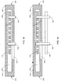
- FIGs. 3A-3F show fixing an IM apparatus to a bone fragment according to one embodiment of the present disclosure.
- an IM nail 110 having at least three locking holes 112 is inserted into a medullary cavity 216 of the bone fragment 210 from the fractured end 212 of the bone fragment 210.
- the IM nail 110 is partially inserted into the medullary cavity 216 such that, as shown in FIG. 3B , at least one of the locking holes 112C is hidden by the bone fragment 210 and at least two of the locking holes 112A and 112B are exposed from the bone fragment 216.
- the two exposed locking holes 112A and 112B may be used for inserting two positioning members 132.
- FIG. 3A an IM nail 110 having at least three locking holes 112 is inserted into a medullary cavity 216 of the bone fragment 210 from the fractured end 212 of the bone fragment 210.
- the IM nail 110 is partially inserted into the medullary cavity 216 such that, as shown in FIG
- the positional reference member 120 is mounted to the IM nail 110 by the two positioning members 132 inserted into the two exposed locking holes 112A and 112B, such that the longitudinal vernier scale 122 on the positional reference member 120 is parallel to the longitudinal axis of the IM nail 110. Since the locking holes 112 on the IM nail 110 are equally distantly defined thereon along the longitudinal axis, the longitudinal vernier scale 122 on the positional reference member 120 may be used as a reference scale to locate the hidden locking hole 112C.
- the position of the hidden locking hole 112C in the bone fragment 210 may be located.
- the doctor may drill a hole on the bone fragment 210 corresponding to the located hidden locking hole 112C such that the IM nail 110 is fixable to the bone fragment 210 by inserting the locking member 134 through the hole to the located hidden locking hole 112C.
- the IM nail 110 is fixed to the bone fragment 210 by inserting the locking member 134 to the located hidden locking hole 112C through the bone fragment 210.
- the positional reference member 120 and the two positioning members 132 may be removed such that the IM nail 110 fixed to the bone fragment 210 is obtained, as shown in FIG. 3F .
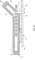
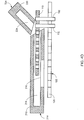
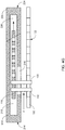
- FIGs. 4A-4I show treating a fractured bone using an IM apparatus according to one embodiment of the present disclosure.
- the fractured bone 200 is fractured into two bone fragments, including a first bone fragment 210 and a second bone fragment 220.
- the first bone fragment 210 has a fractured end 212 and a joint end 214, and has a medullary cavity 216.
- the second bone fragment 220 has a fractured end 222 and a joint end 224, and has a medullary cavity 226.
- the IM nail 110 is inserted into the medullary cavity 216 of the first bone fragment 210 of the fractured bone 200 from the fracture end 212 of the first bone fragment 210.
- at least two of the locking holes 112 are hidden in the first bone fragment 210, and an exposed part of the IM nail 110 from the fracture end 212 of the first bone fragment 210 has at least two of the locking holes 112A and 112B.
- the positional reference member 120 may be mounted to the IM nail 110 by the two positioning members 132 inserted into the at least two exposed locking holes 112A and 112B.
- the doctor may use the longitudinal vernier scale 122 on the positional reference member 120 as a reference for cutting a slot along the longitudinal axis on the first bone fragment 210.
- the slot 216 is formed to have a length such that at least two of the hidden locking holes 112 in the first bone fragment 210 may be exposed through the slot 216.
- the positional reference member 120 and the two positioning members 132 may be removed, and the IM nail 110 may be pushed further into the medullary cavity 216 of the first bone fragment 210 such that at least two of the hidden locking holes 112 are exposed from the slot 216.
- the IM nail 110 is pushed into the medullary cavity 216 of the first bone fragment 210 such that at least two of the hidden locking holes 112C and 112D are exposed from the slot 216. Further, in this position, the exposed part of the IM nail 110 from the fracture end 212 of the first bone fragment 210 is short enough for the second bone fragment 220 to be forced back to its original position without being interfered by the IM nail 110.
- the exposed part of the IM nail 110 is inserted into the medullary cavity 226 of the second bone fragment 220 from the fracture end 222 of the second bone fragment 220 such that the locking hole 112 on the exposed part of the IM nail 110 is now hidden in the second bone fragment 220.
- the positional reference member 120 may be mounted again to the IM nail 110 by the two positioning members 132 inserted into the at least two exposed locking holes 112C and 112D from the slot 216.
- the IM nail 110 is hidden in the medullary cavity 216 of the first bone fragment 210 and the medullary cavity 226 of the second bone fragment 220.
- the positional reference member 120 mounted on the IM nail 110 allows the doctor to push the positional reference member 120 with a force F, such that the IM nail 110 moves towards the second bone fragment 220. In this way, at least one of the locking holes 112 would be hidden in the second bone fragment 220.
- the doctor may use the longitudinal vernier scale 122 on the positional reference member 120 as a reference for locating the hidden locking hole 112 in the second bone fragment 220.
- the doctor may drill a hole on the second bone fragment 220 corresponding to the located hidden locking hole such that the IM nail 110 is fixable to the second bone fragment 220 by inserting the locking member 134 through the hole to the located hidden locking hole 112 in the second bone fragment 220.
- the positional reference member 120 and the two positioning members 132 may be removed, and a locking member 134 may be inserted to the locking hole 112 exposed from the slot 216 to fix the IM nail 110 to the first bone fragment 210.
- the IM nail 110 is now fixed to the first bone fragment 210 and the second bone fragment 220 by the locking members 134.
- the length of the IM nail 110 can be shorter than the length of the medullary cavity 216 of the first bone fragment 210.
- the doctor may control the hidden IM nail 110 with the positional reference member 120 mounted to the IM nail 110 through the slot 216.
- the method of treating the fractured bone may not damage the joint connected to the fractured bone.
- the IM apparatus may further include an additional plate 140 for strengthening the fixing of the IM nail 110.
- the plate 140 may be provided and positioned outside the first and second bone fragments 210 and 220 and detachably fixed to the bone fragments 210 and 220 and the IM nail 110 by the locking members 134.
- the plate 140 may reinforce the structure of the IM nail 110 to provide a strengthened fixing of the fractured bone.
- the locking members 134 and the positioning members 132 may be screws, pins or other fixing or locking structure or device, and the size and length of the locking members 134 and the positioning members 132 may vary. In certain embodiments, the locking members 134 and the positioning members 132 may be the same locking structures or devices. Thus, although the positioning members 132 are shown in the figures as relatively long structures and the locking members 134 are shown in the figures as relatively short structures, the length of the locking members 134 may be the same as or longer than the length of the positioning members 132.
- FIGs. 5A-5D show treating a comminuted fractured bone using an IM apparatus according to one embodiment of the present disclosure.
- the IM nail 110 may be inserted to the two bone fragments 210 and 220 at the two ends of the bone. Specifically, the IM nail 110 is inserted into the medullary cavity of the first bone fragment 210 from its fracture end 212 such that at least one of the locking holes 112C is hidden in the first bone fragment 210, and an exposed part of the IM nail 110 from the fracture end 212 of the first bone fragment 210 has at least three of the locking holes 112.
- the exposed part of the IM nail 110 is inserted into the medullary cavity of the second bone fragment 220 from its fracture end 222 such that at least one of the exposed locking holes 112 is hidden in the second bone fragment 220, and at least two of the locking holes 112 remain exposed.
- the two exposed locking holes 112 may be used for inserting two positioning members 132.
- the positional reference member 120 is mounted to the IM nail 110 by the two positioning members 132 inserted into the two exposed locking holes 112, such that the longitudinal vernier scale 122 on the positional reference member 120 is parallel to the longitudinal axis of the IM nail 110.
- the longitudinal vernier scale 122 on the positional reference member 120 may be used as a reference scale to locate the hidden locking holes 112 in the first bone fragment 210 and the second bone fragment 220.
- the IM nail 110 is fixed to the second bone fragment 220 by inserting two locking members 134 to the located hidden locking holes 112 through the second bone fragment 220. Meanwhile, the positional reference member 120 and the two positioning members 132 may be removed such that the third bone fragment 240 on the top side of the figure may be disposed on the IM nail 110. Similarly, the third bone fragment 230 on the bottom side of the figure may be disposed on the IM nail 110. Each of the third bone fragments 230 and 240 corresponds to at least one of the exposed locking holes 112 such that the third bone fragments 230 and 240 may be respectively fixed to the IM nail 110 by the locking member 134.
- the positional reference member 120 and the two positioning members 132 may be removed and re-mounted to the IM nail 110 for locating the hidden locking holes 112 in the bone fragments.
- FIG. 5C shows that the positional reference member 120 is re-mounted on the bottom side of the figure such that the hidden locking holes 112 in the first bone fragment 210 may be located from the bottom side of the figure.
- FIG. 5D all of the bone fragments 210, 220, 230 and 240 may be fixed to the IM nail 110 by the locking members 134 such that the relative positions of each bone fragment may be maintained.
- the IM apparatus may further include an additional plate 140 for strengthening the fixing of the IM nail 110.
- the plate 140 may be provided and positioned outside the first and second bone fragments 210 and 220 and detachably fixed to the bone fragments 210 and 220 and the IM nail 110 by the locking members 134.
- the plate 140 may reinforce the structure of the IM nail 110 to provide a strengthened fixing of the comminuted fractured bone.
- the method as described in the present disclosure relates to treating a fractured bone of an animal.
- the method can be used on any animal having a fractured bone.
- the animals being treated include human beings, dogs, cats and other mammals, or any other vertebrates with endoskeleton structures or internal bone structures.
- the present disclosure relates to an IM apparatus for treating a fractured bone of an animal and applications of the same.
- the locking holes hidden in the bone fragments may be accurately located by the positional reference member, and the doctor may control the position of the IM nail hidden in the bone fragments by holding the positional reference member mounted to the IM nail.
Landscapes
- Health & Medical Sciences (AREA)
- Surgery (AREA)
- Life Sciences & Earth Sciences (AREA)
- Orthopedic Medicine & Surgery (AREA)
- Biomedical Technology (AREA)
- Public Health (AREA)
- Veterinary Medicine (AREA)
- Engineering & Computer Science (AREA)
- Nuclear Medicine, Radiotherapy & Molecular Imaging (AREA)
- Heart & Thoracic Surgery (AREA)
- Medical Informatics (AREA)
- Molecular Biology (AREA)
- Animal Behavior & Ethology (AREA)
- General Health & Medical Sciences (AREA)
- Oral & Maxillofacial Surgery (AREA)
- Dentistry (AREA)
- Pathology (AREA)
- Neurology (AREA)
- Surgical Instruments (AREA)
Claims (6)
- Intramedulläre (IM) Vorrichtung (100) zur Behandlung eines gebrochenen Knochens eines Tieres, umfassend:einen sich entlang einer Längsachse erstreckenden IM Nagel (110), der wenigstens drei in Richtung der Längsachse gleich weit voneinander entfernt darauf definierte Verriegelungsöffnungen (112) aufweist, wobei der IM Nagel (110) ausgestaltet ist, um in eine Markhöhle eines Knochenfragments des gebrochenen Knochens eingesetzt zu werden, so dass der IM Nagel (110) durch entsprechendes Einsetzen eines Verriegelungselements (134) in eine der Verriegelungsöffnungen (112) durch das Knochenfragment hindurch am Knochenfragment fixierbar ist; undein Positionsreferenzelement (120), das eine darauf befindliche Längsnoniusskala (122) aufweist, wobei das Positionsreferenzelement (120) ausgestaltet ist, um am IM Nagel (110) lösbar durch zwei in zwei der Verriegelungsöffnungen (112) eingesetzte Positionierelemente (132) befestigt zu werden, so dass die Längsnoniusskala (122) zu der Längsachse des IM Nagels (110) parallel ist, und jede Verriegelungsöffnung (112) ist durch die Längsnoniusskala (122) lokalisierbar, wobei die Verriegelungsöffnungen (112) Durchgangsöffnungen sind, die zur Längsachse im Wesentlichen rechtwinkelig sind, dadurch gekennzeichnet, dassdie Verriegelungsöffnungen wenigstens eine in einer vertikalen Richtung rechtwinkelig zur Längsachse ausgerichtete vertikale Verriegelungsöffnung (112), und wenigstens eine in einer horizontalen Richtung rechtwinkelig zur Längsachse ausgerichtete horizontale Verriegelungsöffnung (114) umfassen, wobei sich die wenigstens eine vertikale Verriegelungsöffnung (112) und die wenigstens eine horizontale Verriegelungsöffnung (114) an der Längsachse schneiden.
- IM Vorrichtung nach Anspruch 1, weiter umfassend:eine Platte (140) ausgestaltet, um außerhalb des Knochenfragments positioniert sowie lösbar durch das Verriegelungselement (134) am Knochenfragment und dem IM Nagel (110) fixiert zu werden.
- IM Vorrichtung nach einem der vorhergehenden Ansprüche, wobei das Positionsreferenzelement (120) eine Vielzahl von Befestigungsöffnungen (124) aufweist, die den zwei Positionierelementen (132) entsprechen.
- IM Vorrichtung gemäß einem der vorhergehenden Ansprüche, wobei das Verriegelungselement (134) und die Positionierelemente (132) Schrauben, und die Verriegelungsöffnungen (112) den Schrauben entsprechende Schraubenöffnungen sind.
- IM Vorrichtung gemäß einem der vorhergehenden Ansprüche, wobei der IM Nagel (110) aus einem Metall oder einem auflösbaren künstlichen skelettartigen Material besteht.
- IM Vorrichtung gemäß einem der vorhergehenden Ansprüche, wobei die Verriegelungsöffnungen (112) wenigstens drei in einer vertikalen Richtung rechtwinkelig zur Längsachse ausgerichtete vertikale Verriegelungsöffnungen (112) umfassen.
Applications Claiming Priority (2)
| Application Number | Priority Date | Filing Date | Title |
|---|---|---|---|
| US13/791,357 US8721644B1 (en) | 2013-03-08 | 2013-03-08 | Intramedullary apparatus and methods of treating bone fracture using the same |
| PCT/CN2014/073078 WO2014135124A1 (en) | 2013-03-08 | 2014-03-07 | Intramedullary apparatus and methods of treating bone fracture using the same |
Publications (3)
| Publication Number | Publication Date |
|---|---|
| EP2964121A1 EP2964121A1 (de) | 2016-01-13 |
| EP2964121A4 EP2964121A4 (de) | 2016-02-10 |
| EP2964121B1 true EP2964121B1 (de) | 2017-11-22 |
Family
ID=50635565
Family Applications (1)
| Application Number | Title | Priority Date | Filing Date |
|---|---|---|---|
| EP14760471.4A Not-in-force EP2964121B1 (de) | 2013-03-08 | 2014-03-07 | Intramedulläre vorrichtung und verfahren zur behandlung von knochenbrüchen damit |
Country Status (6)
| Country | Link |
|---|---|
| US (3) | US8721644B1 (de) |
| EP (1) | EP2964121B1 (de) |
| CN (1) | CN105431098B (de) |
| ES (1) | ES2659831T3 (de) |
| TW (1) | TWI619469B (de) |
| WO (1) | WO2014135124A1 (de) |
Families Citing this family (1)
| Publication number | Priority date | Publication date | Assignee | Title |
|---|---|---|---|---|
| TWI618526B (zh) * | 2016-11-08 | 2018-03-21 | 高雄醫學大學 | 一種非侵入式鎖固骨骼之定位系統及方法 |
Family Cites Families (37)
| Publication number | Priority date | Publication date | Assignee | Title |
|---|---|---|---|---|
| FR2515955B1 (fr) * | 1981-11-11 | 1987-11-20 | South African Inventions | Implant chirurgical |
| US4667664A (en) * | 1985-01-18 | 1987-05-26 | Richards Medical Company | Blind hole targeting device for orthopedic surgery |
| US4790302A (en) * | 1986-06-17 | 1988-12-13 | Colwill John C | Method and apparatus for fixing bone fractures |
| US4913137A (en) * | 1988-02-09 | 1990-04-03 | Orthopedic Designs, Inc. | Intramedullary rod system |
| US5354314A (en) * | 1988-12-23 | 1994-10-11 | Medical Instrumentation And Diagnostics Corporation | Three-dimensional beam localization apparatus and microscope for stereotactic diagnoses or surgery mounted on robotic type arm |
| US5989260A (en) * | 1994-08-22 | 1999-11-23 | Yao; Meei-Huei | Intramedullary nail guide rod with measure scale marked thereon |
| US5776137A (en) * | 1995-05-31 | 1998-07-07 | Katz; Lawrence | Method and apparatus for locating bone cuts at the distal condylar femur region to receive a knee prosthesis |
| DE19633865A1 (de) * | 1996-08-16 | 1998-02-19 | Guenter Prof Dr Med Lob | Endoprothese |
| CN2281162Y (zh) * | 1996-12-06 | 1998-05-13 | 戚鸣 | 一种插销髓内钉 |
| US5766179A (en) * | 1997-03-05 | 1998-06-16 | Orthofix S.R.L. | Mechanical system for blind nail-hole alignment of bone screws |
| ATE250390T1 (de) * | 1997-04-11 | 2003-10-15 | Rosas Fernando Colchero | Behandlungssystem für frakturen und andere verletzungen des femurs,der tibia unddes humerus |
| US7056322B2 (en) * | 2002-03-28 | 2006-06-06 | Depuy Orthopaedics, Inc. | Bone fastener targeting and compression/distraction device for an intramedullary nail and method of use |
| US7780664B2 (en) * | 2002-12-10 | 2010-08-24 | Depuy Products, Inc. | Endosteal nail |
| BRPI0318150B8 (pt) | 2003-03-21 | 2021-06-22 | Synthes Ag | garra intramedular |
| US7892234B2 (en) * | 2004-06-22 | 2011-02-22 | Synthes Usa, Llc | Intramedullary nail |
| US7481815B2 (en) * | 2004-09-23 | 2009-01-27 | Synthes (U.S.A.) | Coplanar X-ray guided aiming arm for locking of intramedullary nails |
| US8435238B2 (en) * | 2004-10-05 | 2013-05-07 | Michigan State University | Devices and methods for interlocking surgical screws and nails |
| FR2885513B1 (fr) * | 2005-05-13 | 2007-08-10 | Newdeal S A S Soc Par Actions | Appareillage d'arthrodese pour une articulation, du genre articulation de la cheville, et clou d'athrodese destine a etre utilise dans un tel appareillage |
| US8568413B2 (en) * | 2008-12-18 | 2013-10-29 | Sonoma Orthopedic Products, Inc. | Bone fixation device, tools and methods |
| CN1887235A (zh) * | 2006-07-27 | 2007-01-03 | 周志坚 | 安装交锁髓内针的调整工具及其使用方法 |
| US8685034B2 (en) * | 2006-08-10 | 2014-04-01 | Stryker Trauma Gmbh | Distal targeting device |
| WO2008086501A2 (en) * | 2007-01-11 | 2008-07-17 | Anthem Orthopaedics Llc | Percutaneous intramedullary bone repair device and method for using same |
| US20090177240A1 (en) * | 2007-10-16 | 2009-07-09 | Perez Edward A | Long bone fixation system and methods |
| US8414584B2 (en) * | 2008-07-09 | 2013-04-09 | Icon Orthopaedic Concepts, Llc | Ankle arthrodesis nail and outrigger assembly |
| US8328807B2 (en) * | 2008-07-09 | 2012-12-11 | Icon Orthopaedic Concepts, Llc | Ankle arthrodesis nail and outrigger assembly |
| AT507086B1 (de) * | 2008-09-16 | 2010-02-15 | Haininger Christian Dr | Implantat, insbesondere marknagel für die behandlung einer proximalen humerusfraktur |
| JP2012502753A (ja) * | 2008-09-17 | 2012-02-02 | スケルタル ダイナミクス エルエルシー | 髄内関節固定釘およびその使用方法 |
| US8480677B2 (en) * | 2009-02-20 | 2013-07-09 | Gordon I. Groh | System for treating proximal humeral fractures and method of using the same |
| US20110118740A1 (en) * | 2009-11-10 | 2011-05-19 | Illuminoss Medical, Inc. | Intramedullary Implants Having Variable Fastener Placement |
| US8764751B2 (en) * | 2010-03-04 | 2014-07-01 | Skeletal Dynamics, Llc | Endosteal nail plate for fixing bone segments |
| US8784428B2 (en) * | 2010-09-24 | 2014-07-22 | DePuy Synthes Products, LLC | Device for measuring the degree of bending of an intramedullary nail |
| DE102011053638A1 (de) * | 2011-09-15 | 2013-03-21 | Wittenstein Ag | Marknagel |
| WO2014048447A1 (en) * | 2012-09-27 | 2014-04-03 | Stryker Trauma Gmbh | Rotational position determination |
| US9974588B2 (en) * | 2012-12-27 | 2018-05-22 | Wright Medical Technology, Inc. | Ankle replacement system and method |
| US9351771B2 (en) * | 2013-02-08 | 2016-05-31 | Robert Gorsline | Systems, methods, and apparatuses for fusion, stabilization, or fixation of bones |
| WO2014194965A1 (en) * | 2013-06-07 | 2014-12-11 | Stryker Trauma Gmbh | Targeting adjustment system for an intramedullary nail |
| US9421049B2 (en) * | 2013-09-06 | 2016-08-23 | Richard A. Rogachefsky | Intramedullary rod fixation system |
-
2013
- 2013-03-08 US US13/791,357 patent/US8721644B1/en active Active
-
2014
- 2014-03-07 TW TW103107885A patent/TWI619469B/zh active
- 2014-03-07 WO PCT/CN2014/073078 patent/WO2014135124A1/en not_active Ceased
- 2014-03-07 CN CN201480013001.8A patent/CN105431098B/zh not_active Expired - Fee Related
- 2014-03-07 EP EP14760471.4A patent/EP2964121B1/de not_active Not-in-force
- 2014-03-07 ES ES14760471.4T patent/ES2659831T3/es active Active
- 2014-04-21 US US14/257,292 patent/US9949771B2/en active Active
-
2018
- 2018-04-20 US US15/958,173 patent/US10687870B2/en active Active
Non-Patent Citations (1)
| Title |
|---|
| None * |
Also Published As
| Publication number | Publication date |
|---|---|
| US20140257290A1 (en) | 2014-09-11 |
| US9949771B2 (en) | 2018-04-24 |
| EP2964121A4 (de) | 2016-02-10 |
| EP2964121A1 (de) | 2016-01-13 |
| US20180235679A1 (en) | 2018-08-23 |
| CN105431098B (zh) | 2018-07-13 |
| WO2014135124A1 (en) | 2014-09-12 |
| US10687870B2 (en) | 2020-06-23 |
| CN105431098A (zh) | 2016-03-23 |
| TWI619469B (zh) | 2018-04-01 |
| TW201507690A (zh) | 2015-03-01 |
| US8721644B1 (en) | 2014-05-13 |
| ES2659831T3 (es) | 2018-03-19 |
Similar Documents
| Publication | Publication Date | Title |
|---|---|---|
| US11123115B2 (en) | Orthopedic bone fixation systems and methods | |
| EP2844168B1 (de) | Expandierbare intraossäre fixierungsvorrichtung | |
| KR101694973B1 (ko) | 골절술용 지그 및 톱 가이드 | |
| DE20015775U1 (de) | Knochennagel | |
| KR101740905B1 (ko) | 개방형 근위 경골 절골술을 위한 고정 기구 | |
| EP3375393A1 (de) | Verriegelungsplatte für ersten mittelhandknochen | |
| US10213237B2 (en) | Periprosthetic extension plate | |
| CN102458280A (zh) | 具有锁孔特征的骨接合板 | |
| US10537371B2 (en) | Wrist plate and drill guide | |
| TWI667989B (zh) | 指骨頭板 | |
| US10687870B2 (en) | Intramedullary apparatus and methods of treating bone fracture using the same | |
| US10314629B2 (en) | Fixing pin for orthopedic surgery enabling internal fixation | |
| US20100198266A1 (en) | Biplanar Fracture Fixation | |
| KR101601730B1 (ko) | 골접합 플레이트 및 이를 포함하는 골접합 장치 | |
| EP3422971B1 (de) | Halterung für externe knochenfixierung | |
| US10342580B2 (en) | Bracket for external fixation of bones | |
| US8992528B2 (en) | Intramedullary system for managing a bone fracture | |
| US20090143826A1 (en) | Fastening system and fastening method for reference arrays | |
| CN105581836A (zh) | 一种利于缆线穿设的骨螺钉 | |
| CN105997231A (zh) | 关节软骨网状固定系统 | |
| KR20150106498A (ko) | 골절치료용 철심 |
Legal Events
| Date | Code | Title | Description |
|---|---|---|---|
| PUAI | Public reference made under article 153(3) epc to a published international application that has entered the european phase |
Free format text: ORIGINAL CODE: 0009012 |
|
| 17P | Request for examination filed |
Effective date: 20151007 |
|
| AK | Designated contracting states |
Kind code of ref document: A1 Designated state(s): AL AT BE BG CH CY CZ DE DK EE ES FI FR GB GR HR HU IE IS IT LI LT LU LV MC MK MT NL NO PL PT RO RS SE SI SK SM TR |
|
| AX | Request for extension of the european patent |
Extension state: BA ME |
|
| A4 | Supplementary search report drawn up and despatched |
Effective date: 20160113 |
|
| RIC1 | Information provided on ipc code assigned before grant |
Ipc: A61B 90/90 20160101ALI20160107BHEP Ipc: A61B 17/72 20060101AFI20160107BHEP Ipc: A61B 17/56 20060101ALI20160107BHEP Ipc: A61B 17/17 20060101ALI20160107BHEP |
|
| DAX | Request for extension of the european patent (deleted) | ||
| 17Q | First examination report despatched |
Effective date: 20160920 |
|
| GRAP | Despatch of communication of intention to grant a patent |
Free format text: ORIGINAL CODE: EPIDOSNIGR1 |
|
| INTG | Intention to grant announced |
Effective date: 20170515 |
|
| GRAS | Grant fee paid |
Free format text: ORIGINAL CODE: EPIDOSNIGR3 |
|
| GRAJ | Information related to disapproval of communication of intention to grant by the applicant or resumption of examination proceedings by the epo deleted |
Free format text: ORIGINAL CODE: EPIDOSDIGR1 |
|
| GRAL | Information related to payment of fee for publishing/printing deleted |
Free format text: ORIGINAL CODE: EPIDOSDIGR3 |
|
| GRAR | Information related to intention to grant a patent recorded |
Free format text: ORIGINAL CODE: EPIDOSNIGR71 |
|
| GRAA | (expected) grant |
Free format text: ORIGINAL CODE: 0009210 |
|
| INTC | Intention to grant announced (deleted) | ||
| AK | Designated contracting states |
Kind code of ref document: B1 Designated state(s): AL AT BE BG CH CY CZ DE DK EE ES FI FR GB GR HR HU IE IS IT LI LT LU LV MC MK MT NL NO PL PT RO RS SE SI SK SM TR |
|
| INTG | Intention to grant announced |
Effective date: 20171013 |
|
| REG | Reference to a national code |
Ref country code: GB Ref legal event code: FG4D |
|
| REG | Reference to a national code |
Ref country code: CH Ref legal event code: EP |
|
| REG | Reference to a national code |
Ref country code: IE Ref legal event code: FG4D |
|
| REG | Reference to a national code |
Ref country code: AT Ref legal event code: REF Ref document number: 947656 Country of ref document: AT Kind code of ref document: T Effective date: 20171215 |
|
| REG | Reference to a national code |
Ref country code: DE Ref legal event code: R096 Ref document number: 602014017625 Country of ref document: DE |
|
| REG | Reference to a national code |
Ref country code: NL Ref legal event code: FP |
|
| REG | Reference to a national code |
Ref country code: CH Ref legal event code: NV Representative=s name: MICHELI AND CIE SA, CH |
|
| REG | Reference to a national code |
Ref country code: FR Ref legal event code: PLFP Year of fee payment: 5 |
|
| REG | Reference to a national code |
Ref country code: ES Ref legal event code: FG2A Ref document number: 2659831 Country of ref document: ES Kind code of ref document: T3 Effective date: 20180319 |
|
| REG | Reference to a national code |
Ref country code: LT Ref legal event code: MG4D |
|
| REG | Reference to a national code |
Ref country code: AT Ref legal event code: MK05 Ref document number: 947656 Country of ref document: AT Kind code of ref document: T Effective date: 20171122 |
|
| PG25 | Lapsed in a contracting state [announced via postgrant information from national office to epo] |
Ref country code: LT Free format text: LAPSE BECAUSE OF FAILURE TO SUBMIT A TRANSLATION OF THE DESCRIPTION OR TO PAY THE FEE WITHIN THE PRESCRIBED TIME-LIMIT Effective date: 20171122 Ref country code: FI Free format text: LAPSE BECAUSE OF FAILURE TO SUBMIT A TRANSLATION OF THE DESCRIPTION OR TO PAY THE FEE WITHIN THE PRESCRIBED TIME-LIMIT Effective date: 20171122 Ref country code: SE Free format text: LAPSE BECAUSE OF FAILURE TO SUBMIT A TRANSLATION OF THE DESCRIPTION OR TO PAY THE FEE WITHIN THE PRESCRIBED TIME-LIMIT Effective date: 20171122 Ref country code: NO Free format text: LAPSE BECAUSE OF FAILURE TO SUBMIT A TRANSLATION OF THE DESCRIPTION OR TO PAY THE FEE WITHIN THE PRESCRIBED TIME-LIMIT Effective date: 20180222 |
|
| PG25 | Lapsed in a contracting state [announced via postgrant information from national office to epo] |
Ref country code: AT Free format text: LAPSE BECAUSE OF FAILURE TO SUBMIT A TRANSLATION OF THE DESCRIPTION OR TO PAY THE FEE WITHIN THE PRESCRIBED TIME-LIMIT Effective date: 20171122 Ref country code: GR Free format text: LAPSE BECAUSE OF FAILURE TO SUBMIT A TRANSLATION OF THE DESCRIPTION OR TO PAY THE FEE WITHIN THE PRESCRIBED TIME-LIMIT Effective date: 20180223 Ref country code: HR Free format text: LAPSE BECAUSE OF FAILURE TO SUBMIT A TRANSLATION OF THE DESCRIPTION OR TO PAY THE FEE WITHIN THE PRESCRIBED TIME-LIMIT Effective date: 20171122 Ref country code: RS Free format text: LAPSE BECAUSE OF FAILURE TO SUBMIT A TRANSLATION OF THE DESCRIPTION OR TO PAY THE FEE WITHIN THE PRESCRIBED TIME-LIMIT Effective date: 20171122 Ref country code: LV Free format text: LAPSE BECAUSE OF FAILURE TO SUBMIT A TRANSLATION OF THE DESCRIPTION OR TO PAY THE FEE WITHIN THE PRESCRIBED TIME-LIMIT Effective date: 20171122 Ref country code: BG Free format text: LAPSE BECAUSE OF FAILURE TO SUBMIT A TRANSLATION OF THE DESCRIPTION OR TO PAY THE FEE WITHIN THE PRESCRIBED TIME-LIMIT Effective date: 20180222 |
|
| PG25 | Lapsed in a contracting state [announced via postgrant information from national office to epo] |
Ref country code: SK Free format text: LAPSE BECAUSE OF FAILURE TO SUBMIT A TRANSLATION OF THE DESCRIPTION OR TO PAY THE FEE WITHIN THE PRESCRIBED TIME-LIMIT Effective date: 20171122 Ref country code: DK Free format text: LAPSE BECAUSE OF FAILURE TO SUBMIT A TRANSLATION OF THE DESCRIPTION OR TO PAY THE FEE WITHIN THE PRESCRIBED TIME-LIMIT Effective date: 20171122 Ref country code: CY Free format text: LAPSE BECAUSE OF FAILURE TO SUBMIT A TRANSLATION OF THE DESCRIPTION OR TO PAY THE FEE WITHIN THE PRESCRIBED TIME-LIMIT Effective date: 20171122 Ref country code: EE Free format text: LAPSE BECAUSE OF FAILURE TO SUBMIT A TRANSLATION OF THE DESCRIPTION OR TO PAY THE FEE WITHIN THE PRESCRIBED TIME-LIMIT Effective date: 20171122 Ref country code: CZ Free format text: LAPSE BECAUSE OF FAILURE TO SUBMIT A TRANSLATION OF THE DESCRIPTION OR TO PAY THE FEE WITHIN THE PRESCRIBED TIME-LIMIT Effective date: 20171122 |
|
| REG | Reference to a national code |
Ref country code: DE Ref legal event code: R097 Ref document number: 602014017625 Country of ref document: DE |
|
| PG25 | Lapsed in a contracting state [announced via postgrant information from national office to epo] |
Ref country code: PL Free format text: LAPSE BECAUSE OF FAILURE TO SUBMIT A TRANSLATION OF THE DESCRIPTION OR TO PAY THE FEE WITHIN THE PRESCRIBED TIME-LIMIT Effective date: 20171122 Ref country code: RO Free format text: LAPSE BECAUSE OF FAILURE TO SUBMIT A TRANSLATION OF THE DESCRIPTION OR TO PAY THE FEE WITHIN THE PRESCRIBED TIME-LIMIT Effective date: 20171122 Ref country code: SM Free format text: LAPSE BECAUSE OF FAILURE TO SUBMIT A TRANSLATION OF THE DESCRIPTION OR TO PAY THE FEE WITHIN THE PRESCRIBED TIME-LIMIT Effective date: 20171122 |
|
| PLBE | No opposition filed within time limit |
Free format text: ORIGINAL CODE: 0009261 |
|
| STAA | Information on the status of an ep patent application or granted ep patent |
Free format text: STATUS: NO OPPOSITION FILED WITHIN TIME LIMIT |
|
| 26N | No opposition filed |
Effective date: 20180823 |
|
| PG25 | Lapsed in a contracting state [announced via postgrant information from national office to epo] |
Ref country code: MC Free format text: LAPSE BECAUSE OF FAILURE TO SUBMIT A TRANSLATION OF THE DESCRIPTION OR TO PAY THE FEE WITHIN THE PRESCRIBED TIME-LIMIT Effective date: 20171122 Ref country code: SI Free format text: LAPSE BECAUSE OF FAILURE TO SUBMIT A TRANSLATION OF THE DESCRIPTION OR TO PAY THE FEE WITHIN THE PRESCRIBED TIME-LIMIT Effective date: 20171122 |
|
| REG | Reference to a national code |
Ref country code: BE Ref legal event code: MM Effective date: 20180331 |
|
| REG | Reference to a national code |
Ref country code: IE Ref legal event code: MM4A |
|
| PG25 | Lapsed in a contracting state [announced via postgrant information from national office to epo] |
Ref country code: LU Free format text: LAPSE BECAUSE OF NON-PAYMENT OF DUE FEES Effective date: 20180307 |
|
| PG25 | Lapsed in a contracting state [announced via postgrant information from national office to epo] |
Ref country code: IE Free format text: LAPSE BECAUSE OF NON-PAYMENT OF DUE FEES Effective date: 20180307 |
|
| PG25 | Lapsed in a contracting state [announced via postgrant information from national office to epo] |
Ref country code: BE Free format text: LAPSE BECAUSE OF NON-PAYMENT OF DUE FEES Effective date: 20180331 |
|
| PGFP | Annual fee paid to national office [announced via postgrant information from national office to epo] |
Ref country code: FR Payment date: 20181228 Year of fee payment: 8 |
|
| PGFP | Annual fee paid to national office [announced via postgrant information from national office to epo] |
Ref country code: NL Payment date: 20190326 Year of fee payment: 6 |
|
| PGFP | Annual fee paid to national office [announced via postgrant information from national office to epo] |
Ref country code: ES Payment date: 20190401 Year of fee payment: 6 |
|
| PGFP | Annual fee paid to national office [announced via postgrant information from national office to epo] |
Ref country code: GB Payment date: 20190404 Year of fee payment: 6 |
|
| PG25 | Lapsed in a contracting state [announced via postgrant information from national office to epo] |
Ref country code: MT Free format text: LAPSE BECAUSE OF NON-PAYMENT OF DUE FEES Effective date: 20180307 |
|
| PG25 | Lapsed in a contracting state [announced via postgrant information from national office to epo] |
Ref country code: TR Free format text: LAPSE BECAUSE OF FAILURE TO SUBMIT A TRANSLATION OF THE DESCRIPTION OR TO PAY THE FEE WITHIN THE PRESCRIBED TIME-LIMIT Effective date: 20171122 |
|
| PG25 | Lapsed in a contracting state [announced via postgrant information from national office to epo] |
Ref country code: PT Free format text: LAPSE BECAUSE OF FAILURE TO SUBMIT A TRANSLATION OF THE DESCRIPTION OR TO PAY THE FEE WITHIN THE PRESCRIBED TIME-LIMIT Effective date: 20171122 |
|
| PG25 | Lapsed in a contracting state [announced via postgrant information from national office to epo] |
Ref country code: HU Free format text: LAPSE BECAUSE OF FAILURE TO SUBMIT A TRANSLATION OF THE DESCRIPTION OR TO PAY THE FEE WITHIN THE PRESCRIBED TIME-LIMIT; INVALID AB INITIO Effective date: 20140307 Ref country code: MK Free format text: LAPSE BECAUSE OF NON-PAYMENT OF DUE FEES Effective date: 20171122 |
|
| PG25 | Lapsed in a contracting state [announced via postgrant information from national office to epo] |
Ref country code: AL Free format text: LAPSE BECAUSE OF FAILURE TO SUBMIT A TRANSLATION OF THE DESCRIPTION OR TO PAY THE FEE WITHIN THE PRESCRIBED TIME-LIMIT Effective date: 20171122 Ref country code: IS Free format text: LAPSE BECAUSE OF FAILURE TO SUBMIT A TRANSLATION OF THE DESCRIPTION OR TO PAY THE FEE WITHIN THE PRESCRIBED TIME-LIMIT Effective date: 20180322 |
|
| REG | Reference to a national code |
Ref country code: NL Ref legal event code: MM Effective date: 20200401 |
|
| PG25 | Lapsed in a contracting state [announced via postgrant information from national office to epo] |
Ref country code: NL Free format text: LAPSE BECAUSE OF NON-PAYMENT OF DUE FEES Effective date: 20200401 |
|
| PG25 | Lapsed in a contracting state [announced via postgrant information from national office to epo] |
Ref country code: FR Free format text: LAPSE BECAUSE OF NON-PAYMENT OF DUE FEES Effective date: 20200331 |
|
| GBPC | Gb: european patent ceased through non-payment of renewal fee |
Effective date: 20200307 |
|
| PG25 | Lapsed in a contracting state [announced via postgrant information from national office to epo] |
Ref country code: GB Free format text: LAPSE BECAUSE OF NON-PAYMENT OF DUE FEES Effective date: 20200307 |
|
| REG | Reference to a national code |
Ref country code: ES Ref legal event code: FD2A Effective date: 20210728 |
|
| PG25 | Lapsed in a contracting state [announced via postgrant information from national office to epo] |
Ref country code: IT Free format text: LAPSE BECAUSE OF NON-PAYMENT OF DUE FEES Effective date: 20200307 |
|
| PG25 | Lapsed in a contracting state [announced via postgrant information from national office to epo] |
Ref country code: ES Free format text: LAPSE BECAUSE OF NON-PAYMENT OF DUE FEES Effective date: 20200308 |
|
| PGFP | Annual fee paid to national office [announced via postgrant information from national office to epo] |
Ref country code: DE Payment date: 20220329 Year of fee payment: 9 |
|
| PGFP | Annual fee paid to national office [announced via postgrant information from national office to epo] |
Ref country code: CH Payment date: 20220404 Year of fee payment: 9 |
|
| REG | Reference to a national code |
Ref country code: DE Ref legal event code: R119 Ref document number: 602014017625 Country of ref document: DE |
|
| REG | Reference to a national code |
Ref country code: CH Ref legal event code: PL |
|
| PG25 | Lapsed in a contracting state [announced via postgrant information from national office to epo] |
Ref country code: LI Free format text: LAPSE BECAUSE OF NON-PAYMENT OF DUE FEES Effective date: 20230331 Ref country code: DE Free format text: LAPSE BECAUSE OF NON-PAYMENT OF DUE FEES Effective date: 20231003 Ref country code: CH Free format text: LAPSE BECAUSE OF NON-PAYMENT OF DUE FEES Effective date: 20230331 |