EP2963806A2 - Device and method of 6-step controlling inverter of motor driving system - Google Patents
Device and method of 6-step controlling inverter of motor driving system Download PDFInfo
- Publication number
- EP2963806A2 EP2963806A2 EP14197143.2A EP14197143A EP2963806A2 EP 2963806 A2 EP2963806 A2 EP 2963806A2 EP 14197143 A EP14197143 A EP 14197143A EP 2963806 A2 EP2963806 A2 EP 2963806A2
- Authority
- EP
- European Patent Office
- Prior art keywords
- voltage
- inverter
- controller
- voltage vector
- hexagon
- Prior art date
- Legal status (The legal status is an assumption and is not a legal conclusion. Google has not performed a legal analysis and makes no representation as to the accuracy of the status listed.)
- Granted
Links
- 238000000034 method Methods 0.000 title claims abstract description 31
- 239000013598 vector Substances 0.000 claims description 85
- 238000010586 diagram Methods 0.000 claims description 37
- 230000001360 synchronised effect Effects 0.000 claims description 6
- 238000001514 detection method Methods 0.000 claims description 4
- 239000000446 fuel Substances 0.000 abstract description 9
- 238000006243 chemical reaction Methods 0.000 description 1
- 238000013500 data storage Methods 0.000 description 1
- 230000000694 effects Effects 0.000 description 1
- 238000005516 engineering process Methods 0.000 description 1
- 238000012986 modification Methods 0.000 description 1
- 230000004048 modification Effects 0.000 description 1
- 230000003287 optical effect Effects 0.000 description 1
- 239000003208 petroleum Substances 0.000 description 1
- 230000001737 promoting effect Effects 0.000 description 1
Images


Classifications
-
- B—PERFORMING OPERATIONS; TRANSPORTING
- B60—VEHICLES IN GENERAL
- B60H—ARRANGEMENTS OF HEATING, COOLING, VENTILATING OR OTHER AIR-TREATING DEVICES SPECIALLY ADAPTED FOR PASSENGER OR GOODS SPACES OF VEHICLES
- B60H1/00—Heating, cooling or ventilating [HVAC] devices
- B60H1/00357—Air-conditioning arrangements specially adapted for particular vehicles
- B60H1/00385—Air-conditioning arrangements specially adapted for particular vehicles for vehicles having an electrical drive, e.g. hybrid or fuel cell
- B60H1/004—Air-conditioning arrangements specially adapted for particular vehicles for vehicles having an electrical drive, e.g. hybrid or fuel cell for vehicles having a combustion engine and electric drive means, e.g. hybrid electric vehicles
-
- H—ELECTRICITY
- H02—GENERATION; CONVERSION OR DISTRIBUTION OF ELECTRIC POWER
- H02P—CONTROL OR REGULATION OF ELECTRIC MOTORS, ELECTRIC GENERATORS OR DYNAMO-ELECTRIC CONVERTERS; CONTROLLING TRANSFORMERS, REACTORS OR CHOKE COILS
- H02P6/00—Arrangements for controlling synchronous motors or other dynamo-electric motors using electronic commutation dependent on the rotor position; Electronic commutators therefor
- H02P6/14—Electronic commutators
-
- H—ELECTRICITY
- H02—GENERATION; CONVERSION OR DISTRIBUTION OF ELECTRIC POWER
- H02M—APPARATUS FOR CONVERSION BETWEEN AC AND AC, BETWEEN AC AND DC, OR BETWEEN DC AND DC, AND FOR USE WITH MAINS OR SIMILAR POWER SUPPLY SYSTEMS; CONVERSION OF DC OR AC INPUT POWER INTO SURGE OUTPUT POWER; CONTROL OR REGULATION THEREOF
- H02M7/00—Conversion of ac power input into dc power output; Conversion of dc power input into ac power output
- H02M7/42—Conversion of dc power input into ac power output without possibility of reversal
- H02M7/44—Conversion of dc power input into ac power output without possibility of reversal by static converters
- H02M7/48—Conversion of dc power input into ac power output without possibility of reversal by static converters using discharge tubes with control electrode or semiconductor devices with control electrode
- H02M7/53—Conversion of dc power input into ac power output without possibility of reversal by static converters using discharge tubes with control electrode or semiconductor devices with control electrode using devices of a triode or transistor type requiring continuous application of a control signal
- H02M7/537—Conversion of dc power input into ac power output without possibility of reversal by static converters using discharge tubes with control electrode or semiconductor devices with control electrode using devices of a triode or transistor type requiring continuous application of a control signal using semiconductor devices only, e.g. single switched pulse inverters
- H02M7/5387—Conversion of dc power input into ac power output without possibility of reversal by static converters using discharge tubes with control electrode or semiconductor devices with control electrode using devices of a triode or transistor type requiring continuous application of a control signal using semiconductor devices only, e.g. single switched pulse inverters in a bridge configuration
- H02M7/53871—Conversion of dc power input into ac power output without possibility of reversal by static converters using discharge tubes with control electrode or semiconductor devices with control electrode using devices of a triode or transistor type requiring continuous application of a control signal using semiconductor devices only, e.g. single switched pulse inverters in a bridge configuration with automatic control of output voltage or current
- H02M7/53873—Conversion of dc power input into ac power output without possibility of reversal by static converters using discharge tubes with control electrode or semiconductor devices with control electrode using devices of a triode or transistor type requiring continuous application of a control signal using semiconductor devices only, e.g. single switched pulse inverters in a bridge configuration with automatic control of output voltage or current with digital control
-
- H—ELECTRICITY
- H02—GENERATION; CONVERSION OR DISTRIBUTION OF ELECTRIC POWER
- H02M—APPARATUS FOR CONVERSION BETWEEN AC AND AC, BETWEEN AC AND DC, OR BETWEEN DC AND DC, AND FOR USE WITH MAINS OR SIMILAR POWER SUPPLY SYSTEMS; CONVERSION OF DC OR AC INPUT POWER INTO SURGE OUTPUT POWER; CONTROL OR REGULATION THEREOF
- H02M7/00—Conversion of ac power input into dc power output; Conversion of dc power input into ac power output
- H02M7/42—Conversion of dc power input into ac power output without possibility of reversal
- H02M7/44—Conversion of dc power input into ac power output without possibility of reversal by static converters
- H02M7/48—Conversion of dc power input into ac power output without possibility of reversal by static converters using discharge tubes with control electrode or semiconductor devices with control electrode
- H02M7/53—Conversion of dc power input into ac power output without possibility of reversal by static converters using discharge tubes with control electrode or semiconductor devices with control electrode using devices of a triode or transistor type requiring continuous application of a control signal
- H02M7/537—Conversion of dc power input into ac power output without possibility of reversal by static converters using discharge tubes with control electrode or semiconductor devices with control electrode using devices of a triode or transistor type requiring continuous application of a control signal using semiconductor devices only, e.g. single switched pulse inverters
- H02M7/539—Conversion of dc power input into ac power output without possibility of reversal by static converters using discharge tubes with control electrode or semiconductor devices with control electrode using devices of a triode or transistor type requiring continuous application of a control signal using semiconductor devices only, e.g. single switched pulse inverters with automatic control of output wave form or frequency
- H02M7/5395—Conversion of dc power input into ac power output without possibility of reversal by static converters using discharge tubes with control electrode or semiconductor devices with control electrode using devices of a triode or transistor type requiring continuous application of a control signal using semiconductor devices only, e.g. single switched pulse inverters with automatic control of output wave form or frequency by pulse-width modulation
-
- H—ELECTRICITY
- H02—GENERATION; CONVERSION OR DISTRIBUTION OF ELECTRIC POWER
- H02P—CONTROL OR REGULATION OF ELECTRIC MOTORS, ELECTRIC GENERATORS OR DYNAMO-ELECTRIC CONVERTERS; CONTROLLING TRANSFORMERS, REACTORS OR CHOKE COILS
- H02P21/00—Arrangements or methods for the control of electric machines by vector control, e.g. by control of field orientation
- H02P21/06—Rotor flux based control involving the use of rotor position or rotor speed sensors
- H02P21/10—Direct field-oriented control; Rotor flux feed-back control
-
- H—ELECTRICITY
- H02—GENERATION; CONVERSION OR DISTRIBUTION OF ELECTRIC POWER
- H02P—CONTROL OR REGULATION OF ELECTRIC MOTORS, ELECTRIC GENERATORS OR DYNAMO-ELECTRIC CONVERTERS; CONTROLLING TRANSFORMERS, REACTORS OR CHOKE COILS
- H02P21/00—Arrangements or methods for the control of electric machines by vector control, e.g. by control of field orientation
- H02P21/14—Estimation or adaptation of machine parameters, e.g. flux, current or voltage
- H02P21/20—Estimation of torque
-
- H—ELECTRICITY
- H02—GENERATION; CONVERSION OR DISTRIBUTION OF ELECTRIC POWER
- H02P—CONTROL OR REGULATION OF ELECTRIC MOTORS, ELECTRIC GENERATORS OR DYNAMO-ELECTRIC CONVERTERS; CONTROLLING TRANSFORMERS, REACTORS OR CHOKE COILS
- H02P27/00—Arrangements or methods for the control of AC motors characterised by the kind of supply voltage
- H02P27/04—Arrangements or methods for the control of AC motors characterised by the kind of supply voltage using variable-frequency supply voltage, e.g. inverter or converter supply voltage
- H02P27/06—Arrangements or methods for the control of AC motors characterised by the kind of supply voltage using variable-frequency supply voltage, e.g. inverter or converter supply voltage using dc to ac converters or inverters
- H02P27/08—Arrangements or methods for the control of AC motors characterised by the kind of supply voltage using variable-frequency supply voltage, e.g. inverter or converter supply voltage using dc to ac converters or inverters with pulse width modulation
- H02P27/085—Arrangements or methods for the control of AC motors characterised by the kind of supply voltage using variable-frequency supply voltage, e.g. inverter or converter supply voltage using dc to ac converters or inverters with pulse width modulation wherein the PWM mode is adapted on the running conditions of the motor, e.g. the switching frequency
-
- F—MECHANICAL ENGINEERING; LIGHTING; HEATING; WEAPONS; BLASTING
- F16—ENGINEERING ELEMENTS AND UNITS; GENERAL MEASURES FOR PRODUCING AND MAINTAINING EFFECTIVE FUNCTIONING OF MACHINES OR INSTALLATIONS; THERMAL INSULATION IN GENERAL
- F16H—GEARING
- F16H59/00—Control inputs to control units of change-speed-, or reversing-gearings for conveying rotary motion
- F16H59/36—Inputs being a function of speed
- F16H2059/366—Engine or motor speed
Definitions
- the present disclosure relates to a device and a method of 6-step controlling an inverter of a motor driving system. More particularly, it relates to a device and a method of a 6-step control of an inverter of a motor driving system, which applies a voltage to a motor by applying a 6-step control scheme that uses an input voltage of an inverter to improve output efficiency of the inverter and the motor.
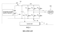
- a motor driving system for driving a motor includes, as illustrated in FIG. 1 , a power supply device for an inverter or a battery 100, configured to supply a direct current voltage to the inverter, a main relay 102 switched for application of the direct current voltage to the inverter 200, the inverter 200 configured to receive the direct current (DC) voltage when the main relay 102 is operated, and convert the received direct current voltage to an alternating current (AC) voltage, and a motor 300 (e.g., three-phase alternating current motor) driven by the alternating current voltage applied from the inverter.
- a power supply device for an inverter or a battery 100 configured to supply a direct current voltage to the inverter
- a main relay 102 switched for application of the direct current voltage to the inverter 200 the inverter 200 configured to receive the direct current (DC) voltage when the main relay 102 is operated, and convert the received direct current voltage to an alternating current (AC) voltage
- a motor 300 e.g., three-phase alternating
- the inverter is configured to generate the direct current voltage input from the power supply device for the inverter or the battery into the alternating current voltage by on-off controlling a switching device (e.g., turning the switching device on and off) through pulse width modulation (PWM), and supply the generated alternating current voltage to the motor for driving the motor.
- a switching device e.g., turning the switching device on and off
- PWM pulse width modulation
- the alternating current voltage is supplied from the inverter to the motor in 6-steps by an operation of the inverter, it may be possible to reduce a current consumed by the motor under the same output condition.
- the supply of the voltage to the motor in the 6-steps may improve efficiency of a system of an environmentally-friendly vehicle, such as an electric vehicle, a hybrid vehicle, and a fuel cell vehicle, in which the motor is mounted, and provide a fuel efficiency improvement effect, as well as improve output and efficiency of the inverter and the motor.
- an environmentally-friendly vehicle such as an electric vehicle, a hybrid vehicle, and a fuel cell vehicle, in which the motor is mounted
- a developed related art discloses a control device and a control method for a motor driving system that include a control configuration switched between a pulse width modulation (PWM) control mode and a rectangular wave voltage control mode.
- Another related art discloses an AC motor driving controller that includes an overmodulation PWM controller configured to calculate a d-axis voltage instruction and a q-axis voltage instruction in which a voltage amplitude exceeds a peak value of a triangular waveform carrier.
- the above described related art are technologies for estimating a torque using values detected by a current sensor and a position sensor and motor currents (Id, Iq), and using the estimated torque for controlling feedback of the torque, but have disadvantages described below.
- a mode switch e.g., overmodulation control ⁇ 6-step phase control
- a voltage vector phase calculator configured to estimate a torque
- the present invention provides a device and a method of 6-step controlling an inverter of a motor driving system, which apply a 6-step control scheme using an input voltage of an inverter and using a voltage use rate applied to a motor to improve output and efficiency of the inverter and the motor, and improve fuel efficiency of an environmentally-friendly vehicle.
- the present invention provides a device for 6-step controlling an inverter of a motor driving system that may include: a current command map configured to generate a d/q axis current command; a current controller configured to generate a voltage command using a difference component between a d/q axis current requested by the current command map and a d/q axis current actually measured by a current sensor; and an inverter 6-step controller configured to detect a voltage vector phase from a voltage command output from the current controller, generate a switching frequency for 12-sample phase controlling using the detected voltage vector phase component, and apply a voltage command that corresponds to each of vertexes of a hexagon of a voltage vector diagram corresponding to a maximum voltage use rate to an inverter using the generated frequencies.
- the inverter 6-step controller may include: a frequency updating unit including a 12-sample phase control switching frequency calculating unit configured to calculate a switching frequency component for the 12-sample phase control using the voltage vector phase obtained through a voltage vector phase detection unit; and a current control task unit including a voltage vector phase detecting unit, configured to detect a voltage vector phase using a voltage command output from the current controller and provide the 12-sample phase control switching frequency calculating unit with the detected voltage vector phase, and a high gain over voltage modulation (HOVM) controller configured to generate a high gain over voltage modulated output voltage by multiplying an output voltage of the current controller by a gain, generate the high gain over voltage modulated output voltage by 12 times per one period of a fundamental wave based on the switching frequencies for the 12-sample phase control, change a pulse width modulation (PWM) period to cause voltage vectors to be substantially symmetric based on the vertexes to converge the actual voltage vector to the vertex of the hexagon of the voltage vector diagram, and adjust a voltage
- PWM pulse
- the frequency updating unit may further include a switching frequency switching unit configured to switch one of the switching frequencies for the 12-sample phase control calculated by the 12-sample phase control switching frequency calculating unit or predetermined switching frequencies to an updated frequency signal, and transmit the updated frequency signal to the current control task unit.
- a switching frequency switching unit configured to switch one of the switching frequencies for the 12-sample phase control calculated by the 12-sample phase control switching frequency calculating unit or predetermined switching frequencies to an updated frequency signal, and transmit the updated frequency signal to the current control task unit.
- the present invention provides a method of 6-step controlling an inverter of a motor driving system that may include: generating a voltage command using a difference component between a d/q axis current requested by a current command map and an actually measured d/q axis current; and 6-step controlling of an inverter by detecting a voltage vector phase from the voltage command, generating switching frequencies for 12-sample phase control using the detected voltage vector phase component, and applying a voltage command that corresponds to each of vertexes of a hexagon of a voltage vector diagram corresponding to a maximum voltage use rate using the generated frequencies to the inverter.
- the present invention provides a method of 6-step controlling an inverter of a motor driving system that may include: detecting a voltage vector phase from a specific voltage command; and 6-step controlling of an inverter by generating switching frequencies for 12-sample phase control using the detected voltage vector phase component, and applying a voltage command corresponding to each of vertexes of a hexagon of a voltage vector diagram that corresponds to a maximum voltage use rate using the generated frequencies to the inverter.
- the 6-step controlling of the inverter may include, when the voltage command corresponding to each of the vertexes of the hexagon of the voltage vector diagram is applied to the inverter, generating a high gain over voltage modulated output voltage by multiplying an output voltage of a current controller by a gain, generating the high gain over voltage modulated output voltage by 12 times per one period of a fundamental wave based on the switching frequencies for the 12-sample phase control, changing a pulse width modulation (PWM) period to cause voltage vectors to be symmetric based on the vertexes to converge the actual voltage vector to the vertex of the hexagon of the voltage vector diagram, and adjusting a voltage vector phase, and applying a voltage command that corresponds to the vertex of the hexagon of the voltage vector diagram to the inverter through minimum distance overmodulation control.
- PWM pulse width modulation
- the minimum distance overmodulation control may be performed to cause the voltage applied to the inverter to generate a waveform with the 6 steps to a square wave, and may include a process of calculating a virtual vector value obtained by multiplying a voltage vector that corresponds to an inscribed circle of the hexagon of the voltage vector diagram indicating 100% of an inverter voltage use rate by a constant, and a process of virtually drawing a vertical line converged to the vertex of the hexagon indicating 110% or greater of the inverter voltage use rate from the virtual vector value.
- the 6-step controlling of the inverter may further include generating the switching frequencies for the 12-sample phase control, and determining whether to perform the 6-step control of the inverter based on whether the switching frequencies meet a 12-sample phase control condition.
- the 12-sample phase control condition may be set based on a speed and a torque of a motor, and an input voltage of the inverter.
- a PWM signal which is a final output voltage signal for the inverter
- a PWM signal which is a final output voltage signal for the inverter
- a PWM signal which is a final output voltage signal for the inverter
- a 6-step voltage may be applied to a driving motor by the inverter 6-step control scheme, to maximally use a voltage use rate applicable to the driving motor, improve output and efficiency of the motor, and improve fuel efficiency of an environmentally-friendly vehicle.
- vehicle or “vehicular” or other similar term as used herein is inclusive of motor vehicles in general such as passenger automobiles including sports utility vehicles (SUV), buses, trucks, various commercial vehicles, watercraft including a variety of boats and ships, aircraft, and the like, and includes hybrid vehicles, electric vehicles, plug-in hybrid electric vehicles, hydrogen-powered vehicles and other alternative fuel vehicles (e.g. fuels derived from resources other than petroleum).
- a hybrid vehicle is a vehicle that has two or more sources of power, for example both gasoline-powered and electric-powered vehicles.
- controller/control unit refers to a hardware device that includes a memory and a processor.
- the memory is configured to store the modules and the processor is specifically configured to execute said modules to perform one or more processes which are described further below.
- control logic of the present invention may be embodied as non-transitory computer readable media on a computer readable medium containing executable program instructions executed by a processor, controller/control unit or the like.
- the computer readable mediums include, but are not limited to, ROM, RAM, compact disc (CD)-ROMs, magnetic tapes, floppy disks, flash drives, smart cards and optical data storage devices.
- the computer readable recording medium can also be distributed in network coupled computer systems so that the computer readable media is stored and executed in a distributed fashion, e.g., by a telematics server or a Controller Area Network (CAN).
- a telematics server or a Controller Area Network (CAN).
- CAN Controller Area Network
- the present invention focuses a 6-step control scheme capable of maximally using an input voltage of an inverter and may be applied to an inverter control process to maximally use a voltage use rate applied to a motor, in consideration of a fact that when an alternating current voltage is supplied from an inverter to a motor in 6 steps by an operation of the inverter, it may be possible to reduce a current consumed by the motor under the same output condition.
- FIG. 2 is an exemplary control block diagram illustrating a device for 6-step controlling an inverter of a motor driving system according to the present invention
- FIG. 3 is an exemplary flowchart illustrating a method of 6-step controlling an inverter of a motor driving system according to the present invention.
- an inverter 6-step controller may include a current command map 10 and a current controller 11 both disposed at an input side of an inverter 17.
- the inverter 6-step controller may be configured to detect a voltage vector phase from a voltage command output from the current controller 10 to maximally use a voltage use rate applied to the motor, generate a switching frequency for phase-controlling 12 samples using the detected voltage vector phase component, and then apply a voltage command that corresponds to each of vertexes of a hexagon of a voltage vector diagram corresponding to a maximum voltage use rate to the inverter using the generated frequency to execute a series of inverter 6-step control logic.
- the inverter 6-step controller may be divided into a frequency updating unit 30 configured to calculate a 12-sample phase control switching frequency and provide a current control task unit 20 with the calculated 12-sample phase control switching frequency, and the current control task unit 20 configured to operate the inverter 17 with the 12-sample phase control switching frequency provided from the frequency updating unit 30.
- the frequency updating unit 30 may include a 12-sample phase control switching frequency calculating unit 14 configured to calculate switching frequency components for 12-sample phase control using the voltage vector phase calculated through the voltage vector phase detecting unit 13, and a switching frequency switching unit 15 configured to switch one of the switching frequencies for the 12 sample phase controlling calculated by the 12-sample phase control switching frequency calculating unit 14 or predetermined switching frequencies to an updated frequency signal, and transmit the updated frequency signal to the current control task unit 20.
- a 12-sample phase control switching frequency calculating unit 14 configured to calculate switching frequency components for 12-sample phase control using the voltage vector phase calculated through the voltage vector phase detecting unit 13, and a switching frequency switching unit 15 configured to switch one of the switching frequencies for the 12 sample phase controlling calculated by the 12-sample phase control switching frequency calculating unit 14 or predetermined switching frequencies to an updated frequency signal, and transmit the updated frequency signal to the current control task unit 20.
- the current control task unit 30 may include a voltage vector phase detecting unit 13 configured to detect a voltage vector phase using a voltage command output from the current controller 11 and then provide the 12-sample phase control switching frequency calculating unit 14 with the detected voltage vector phase, and a high gain over voltage modulation controller 16 configured to generate an output voltage (VdqssHOVM) high gain over voltage modulated 12 times per one period of a fundamental wave by multiplying an output voltage (VdqssRef) of a current controller output from the frequency updating unit 30 based on the switching frequencies for the 12-sample phase control by a gain, and then apply a voltage command that corresponds to each of the vertexes of the hexagon of the voltage vector diagram to the inverter through minimum distance overmodulation control.
- VdqssHOVM output voltage
- VdqssRef output voltage
- the current command map 10 may be configured to generate a d/q axis current command for driving the motor, and input the generated current command into the current controller 11.
- a u/v phase current actually measured by the current sensor 12 disposed at an output side of the inverter may be converted to a d/q axis current through coordinate conversion to be input into the current controller 11.
- the current command map 10 may be configured to generate the voltage command using a different component between the d/q axis current instructed by the current controller 11 and the actually measured d/q axis current, to cause the current command map 10 to generate the voltage command (e.g., stationary coordinate system) using a PI controller within the current controller 11.
- the voltage vector phase detecting unit 13 may be configured to detect a voltage vector phase using the voltage command (stationary coordinate system) output from the current controller 11.
- the present invention may be used in a control scheme of generating and using a specific voltage command (e.g., V/f control and the like), the inverter 6-step control described below may be applied as it is after the detection of the voltage vector phase.
- the 12 sample phase control switching frequency calculating unit 15 may be configured to calculate the switching frequency components for the 12-sample phase control using the voltage vector phase calculated through the voltage vector phase detecting unit 13.
- the voltage vector phase detected by the voltage vector phase detecting unit 13 may be expressed by a hexagonal stationary coordinate system as an inverter voltage vector diagram as illustrated in FIG. 4 .
- an inscribed circle of the hexagon represents an inverter maximum voltage, that is, 100% of an inverter voltage use rate.
- the present invention focuses a fact that it may be possible to decrease a current amount over the output, and thus reduce the amount of battery consumption and promote improvement in fuel efficiency of an environmentally-friendly vehicle by increasing a voltage component entering the motor 18 by 110% or greater and outputting the increased voltage component by improving the inverter voltage use rate by 110% or greater.
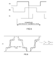
- the 12-sample phase control switching frequency calculating unit 15 may be configured to generate the switching frequencies for the 12-sample phase control using the voltage vector phase component detected by the voltage vector phase detection unit 13, and the generated switching frequencies for the 12-sample phase control may have 12 samples per one period of the fundamental wave for each 3-phase electrical angular frequency as illustrated in FIG. 5 , and the 12 samples mean frequency components for the phase control for generating 12 points with a substantially equal interval on respective sides of the hexagon of the voltage vector diagram.
- the 12-sample phase control condition may be set based on a speed of the motor, a torque of the motor, and an input voltage of the inverter.
- the PWM signal which is a final output voltage signal for the inverter, may be synchronized to a predetermined switching frequency Fsw to be used for the inverter control.
- the switching frequency switching unit 16 may be configured to perform variable switching and transmit a switching frequency (Fsamp) for the 12-sample phase control to the current control task unit 20 as an update signal.
- the PWM signal which is the final output voltage signal for the inverter
- the current control task unit 20 may be configured to perform the substantial inverter 6-step control of applying the voltage command that corresponds to each of the vertexes of the hexagon of the voltage vector diagram corresponding to the maximum voltage use rate to the inverter using the 12-sample phase control switching frequencies from the frequency updating unit 30.
- the HOVM controller 14 may be configured to generate the output voltage (VdqssHOVM) high gain over voltage modulated by 12 times per one period of the fundamental wave by multiplying the output voltage (VdqssRef) of the current controller by a gain, and then apply a voltage command that corresponds to each of the vertexes of the hexagon of the voltage vector diagram to the inverter through the minimum distance overmodulation control.
- the minimum distance overmodulation control may be performed to cause the voltage applied to the inverter to generate a 6-step wave to a square wave, and as illustrated in the voltage vector diagram of FIG. 4 , and may include a process of calculating a virtual vector value obtained by multiplying a voltage vector that corresponds to an inscribed circle of the hexagon of the voltage vector diagram indicating 100% of the inverter voltage use rate by a constant, and a process of virtually drawing a vertical line converged to the vertex of the hexagon indicating 110% or greater of the inverter voltage use rate from the virtual vector value.
- the HOVM controller 14, which is the voltage use rate controller may be configured to apply the voltage command that corresponds to each of the vertexes of the hexagon of the voltage vector diagram to the inverter 17 as the PWM signal, to apply the 6-step voltage from the inverter 17 to the driving motor 18.
- the 6-step voltage may be applied to the driving motor by the inverter 6-step control method, to maximally use the voltage use rate (e.g., about 110%) applicable to the driving motor as illustrated in FIG. 6 .
- the 6-step voltage may be applied to the driving motor by using 110 % V dc 3 ⁇ 1.1 or greater of the voltage use rate that corresponds to each of the vertexes of the hexagon as the 100% V dc 3 of the inverter voltage use rate corresponding to the inscribed circle of the hexagon of the voltage vector diagram, to improve output and efficiency of the motor, and reduce a current consumed by the motor under the same output condition, thereby promoting improvement in fuel efficiency of an environmentally-friendly vehicle.
Abstract
Description
- The present disclosure relates to a device and a method of 6-step controlling an inverter of a motor driving system. More particularly, it relates to a device and a method of a 6-step control of an inverter of a motor driving system, which applies a voltage to a motor by applying a 6-step control scheme that uses an input voltage of an inverter to improve output efficiency of the inverter and the motor.
- In general, a motor driving system for driving a motor includes, as illustrated in
FIG. 1 , a power supply device for an inverter or abattery 100, configured to supply a direct current voltage to the inverter, amain relay 102 switched for application of the direct current voltage to theinverter 200, theinverter 200 configured to receive the direct current (DC) voltage when themain relay 102 is operated, and convert the received direct current voltage to an alternating current (AC) voltage, and a motor 300 (e.g., three-phase alternating current motor) driven by the alternating current voltage applied from the inverter. - The inverter is configured to generate the direct current voltage input from the power supply device for the inverter or the battery into the alternating current voltage by on-off controlling a switching device (e.g., turning the switching device on and off) through pulse width modulation (PWM), and supply the generated alternating current voltage to the motor for driving the motor. In particular, when the alternating current voltage is supplied from the inverter to the motor in 6-steps by an operation of the inverter, it may be possible to reduce a current consumed by the motor under the same output condition. The supply of the voltage to the motor in the 6-steps may improve efficiency of a system of an environmentally-friendly vehicle, such as an electric vehicle, a hybrid vehicle, and a fuel cell vehicle, in which the motor is mounted, and provide a fuel efficiency improvement effect, as well as improve output and efficiency of the inverter and the motor.
- A developed related art discloses a control device and a control method for a motor driving system that include a control configuration switched between a pulse width modulation (PWM) control mode and a rectangular wave voltage control mode. Another related art discloses an AC motor driving controller that includes an overmodulation PWM controller configured to calculate a d-axis voltage instruction and a q-axis voltage instruction in which a voltage amplitude exceeds a peak value of a triangular waveform carrier. The above described related art are technologies for estimating a torque using values detected by a current sensor and a position sensor and motor currents (Id, Iq), and using the estimated torque for controlling feedback of the torque, but have disadvantages described below.
- First, since it may not be possible to use a current control loop when the 6-step control is applied, a mode switch (e.g., overmodulation control ↔ 6-step phase control) technique having no discontinuity is additionally required, and a voltage vector phase calculator configured to estimate a torque is required to be additionally developed.
- Second, since the related art uses a closed-loop torque control scheme through estimation of a torque, a high accuracy torque estimator with a satisfied level is additionally required, and a high accuracy loss map is required to estimate a torque using a phase voltage and a phase current.
- The above information disclosed in this section is merely for enhancement of understanding of the background of the invention and therefore it may contain information that does not form the prior art that is already known in this country to a person of ordinary skill in the art.
- The present invention provides a device and a method of 6-step controlling an inverter of a motor driving system, which apply a 6-step control scheme using an input voltage of an inverter and using a voltage use rate applied to a motor to improve output and efficiency of the inverter and the motor, and improve fuel efficiency of an environmentally-friendly vehicle.
- In one aspect, the present invention provides a device for 6-step controlling an inverter of a motor driving system that may include: a current command map configured to generate a d/q axis current command; a current controller configured to generate a voltage command using a difference component between a d/q axis current requested by the current command map and a d/q axis current actually measured by a current sensor; and an inverter 6-step controller configured to detect a voltage vector phase from a voltage command output from the current controller, generate a switching frequency for 12-sample phase controlling using the detected voltage vector phase component, and apply a voltage command that corresponds to each of vertexes of a hexagon of a voltage vector diagram corresponding to a maximum voltage use rate to an inverter using the generated frequencies.
- In an exemplary embodiment, the inverter 6-step controller may include: a frequency updating unit including a 12-sample phase control switching frequency calculating unit configured to calculate a switching frequency component for the 12-sample phase control using the voltage vector phase obtained through a voltage vector phase detection unit; and a current control task unit including a voltage vector phase detecting unit, configured to detect a voltage vector phase using a voltage command output from the current controller and provide the 12-sample phase control switching frequency calculating unit with the detected voltage vector phase, and a high gain over voltage modulation (HOVM) controller configured to generate a high gain over voltage modulated output voltage by multiplying an output voltage of the current controller by a gain, generate the high gain over voltage modulated output voltage by 12 times per one period of a fundamental wave based on the switching frequencies for the 12-sample phase control, change a pulse width modulation (PWM) period to cause voltage vectors to be substantially symmetric based on the vertexes to converge the actual voltage vector to the vertex of the hexagon of the voltage vector diagram, and adjust a voltage vector phase, and apply a voltage command that corresponds to the vertex of the hexagon of the voltage vector diagram to the inverter through minimum distance overmodulation control.
- In another exemplary embodiment, the frequency updating unit may further include a switching frequency switching unit configured to switch one of the switching frequencies for the 12-sample phase control calculated by the 12-sample phase control switching frequency calculating unit or predetermined switching frequencies to an updated frequency signal, and transmit the updated frequency signal to the current control task unit.
- Further, the present invention provides a method of 6-step controlling an inverter of a motor driving system that may include: generating a voltage command using a difference component between a d/q axis current requested by a current command map and an actually measured d/q axis current; and 6-step controlling of an inverter by detecting a voltage vector phase from the voltage command, generating switching frequencies for 12-sample phase control using the detected voltage vector phase component, and applying a voltage command that corresponds to each of vertexes of a hexagon of a voltage vector diagram corresponding to a maximum voltage use rate using the generated frequencies to the inverter.
- In still another aspect, the present invention provides a method of 6-step controlling an inverter of a motor driving system that may include: detecting a voltage vector phase from a specific voltage command; and 6-step controlling of an inverter by generating switching frequencies for 12-sample phase control using the detected voltage vector phase component, and applying a voltage command corresponding to each of vertexes of a hexagon of a voltage vector diagram that corresponds to a maximum voltage use rate using the generated frequencies to the inverter.
- In an exemplary embodiment, the 6-step controlling of the inverter may include, when the voltage command corresponding to each of the vertexes of the hexagon of the voltage vector diagram is applied to the inverter, generating a high gain over voltage modulated output voltage by multiplying an output voltage of a current controller by a gain, generating the high gain over voltage modulated output voltage by 12 times per one period of a fundamental wave based on the switching frequencies for the 12-sample phase control, changing a pulse width modulation (PWM) period to cause voltage vectors to be symmetric based on the vertexes to converge the actual voltage vector to the vertex of the hexagon of the voltage vector diagram, and adjusting a voltage vector phase, and applying a voltage command that corresponds to the vertex of the hexagon of the voltage vector diagram to the inverter through minimum distance overmodulation control.
- In another exemplary embodiment, the minimum distance overmodulation control may be performed to cause the voltage applied to the inverter to generate a waveform with the 6 steps to a square wave, and may include a process of calculating a virtual vector value obtained by multiplying a voltage vector that corresponds to an inscribed circle of the hexagon of the voltage vector diagram indicating 100% of an inverter voltage use rate by a constant, and a process of virtually drawing a vertical line converged to the vertex of the hexagon indicating 110% or greater of the inverter voltage use rate from the virtual vector value.
- In still another exemplary embodiment, the 6-step controlling of the inverter may further include generating the switching frequencies for the 12-sample phase control, and determining whether to perform the 6-step control of the inverter based on whether the switching frequencies meet a 12-sample phase control condition.
- In addition, the 12-sample phase control condition may be set based on a speed and a torque of a motor, and an input voltage of the inverter. When the 12-sample phase control condition is not satisfied, a PWM signal, which is a final output voltage signal for the inverter, may be synchronized to a predetermined switching frequency to be used for the control of the inverter. When the 12-sample phase control condition is satisfied, a PWM signal, which is a final output voltage signal for the inverter, may be synchronized to the switching frequencies for the 12-sample phase control to be used for the control of the inverter.
- According to the present invention, a 6-step voltage may be applied to a driving motor by the inverter 6-step control scheme, to maximally use a voltage use rate applicable to the driving motor, improve output and efficiency of the motor, and improve fuel efficiency of an environmentally-friendly vehicle.
- The above and other features of the present invention will now be described in detail with reference to exemplary embodiments thereof illustrated in the accompanying drawings which are given hereinbelow by way of illustration only, and thus are not limitative of the present invention, and wherein:
-
FIG. 1 is an exemplary block diagram illustrating a configuration of a motor driving system according to the related art; -
FIG. 2 is an exemplary control block diagram illustrating a device for 6-step controlling an inverter of a motor driving system according to an exemplary embodiment of the present invention; -
FIG. 3 is an exemplary flowchart illustrating a method of 6-step controlling an inverter of a motor driving system according to an exemplary embodiment of the present invention; -
FIG. 4 is an exemplary conceptual diagram illustrating a voltage vector and overmodulation for 6-step controlling the inverter of the motor driving system according to an exemplary embodiment of the present invention; -
FIG. 5 is an exemplary waveform diagram illustrating electrical angular frequencies of 12 samples for 6-step controlling the inverter of the motor driving system according to an exemplary embodiment of the present invention; and -
FIG. 6 is an exemplary waveform diagram illustrating a 6-step waveform for 6-step controlling the inverter of the motor driving system according to an exemplary embodiment of the present invention. - It should be understood that the appended drawings are not necessarily to scale, presenting a somewhat simplified representation of various features illustrative of the basic principles of the invention. The specific design features of the present invention as disclosed herein, including, for example, specific dimensions, orientations, locations, and shapes will be determined in part by the particular intended application and use environment. In the figures, reference numbers refer to the same or equivalent parts of the present invention throughout the several figures of the drawing.
- It is understood that the term "vehicle" or "vehicular" or other similar term as used herein is inclusive of motor vehicles in general such as passenger automobiles including sports utility vehicles (SUV), buses, trucks, various commercial vehicles, watercraft including a variety of boats and ships, aircraft, and the like, and includes hybrid vehicles, electric vehicles, plug-in hybrid electric vehicles, hydrogen-powered vehicles and other alternative fuel vehicles (e.g. fuels derived from resources other than petroleum). As referred to herein, a hybrid vehicle is a vehicle that has two or more sources of power, for example both gasoline-powered and electric-powered vehicles.
- Although exemplary embodiment is described as using a plurality of units to perform the exemplary process, it is understood that the exemplary processes may also be performed by one or plurality of modules. Additionally, it is understood that the term controller/control unit refers to a hardware device that includes a memory and a processor. The memory is configured to store the modules and the processor is specifically configured to execute said modules to perform one or more processes which are described further below.
- Furthermore, control logic of the present invention may be embodied as non-transitory computer readable media on a computer readable medium containing executable program instructions executed by a processor, controller/control unit or the like. Examples of the computer readable mediums include, but are not limited to, ROM, RAM, compact disc (CD)-ROMs, magnetic tapes, floppy disks, flash drives, smart cards and optical data storage devices. The computer readable recording medium can also be distributed in network coupled computer systems so that the computer readable media is stored and executed in a distributed fashion, e.g., by a telematics server or a Controller Area Network (CAN).
- The terminology used herein is for the purpose of describing particular embodiments only and is not intended to be limiting of the invention. As used herein, the singular forms "a", "an" and "the" are intended to include the plural forms as well, unless the context clearly indicates otherwise. It will be further understood that the terms "comprises" and/or "comprising," when used in this specification, specify the presence of stated features, integers, steps, operations, elements, and/or components, but do not preclude the presence or addition of one or more other features, integers, steps, operations, elements, components, and/or groups thereof. As used herein, the term "and/or" includes any and all combinations of one or more of the associated listed items.
- Hereinafter reference will now be made in detail to various exemplary embodiments of the present invention, examples of which are illustrated in the accompanying drawings and described below. While the invention will be described in conjunction with exemplary embodiments, it will be understood that the present description is not intended to limit the invention to those exemplary embodiments. On the contrary, the invention is intended to cover not only the exemplary embodiments, but also various alternatives, modifications, equivalents and other exemplary embodiments, which may be included within the spirit and scope of the invention as defined by the appended claims.
- Hereinafter, an exemplary embodiment of the present invention will be described in detail with reference to the accompanying drawings. The present invention focuses a 6-step control scheme capable of maximally using an input voltage of an inverter and may be applied to an inverter control process to maximally use a voltage use rate applied to a motor, in consideration of a fact that when an alternating current voltage is supplied from an inverter to a motor in 6 steps by an operation of the inverter, it may be possible to reduce a current consumed by the motor under the same output condition.
-
FIG. 2 is an exemplary control block diagram illustrating a device for 6-step controlling an inverter of a motor driving system according to the present invention, andFIG. 3 is an exemplary flowchart illustrating a method of 6-step controlling an inverter of a motor driving system according to the present invention. As illustrated inFIG. 2 , an inverter 6-step controller may include acurrent command map 10 and acurrent controller 11 both disposed at an input side of aninverter 17. - The inverter 6-step controller may be configured to detect a voltage vector phase from a voltage command output from the
current controller 10 to maximally use a voltage use rate applied to the motor, generate a switching frequency for phase-controlling 12 samples using the detected voltage vector phase component, and then apply a voltage command that corresponds to each of vertexes of a hexagon of a voltage vector diagram corresponding to a maximum voltage use rate to the inverter using the generated frequency to execute a series of inverter 6-step control logic. Accordingly, the inverter 6-step controller may be divided into afrequency updating unit 30 configured to calculate a 12-sample phase control switching frequency and provide a currentcontrol task unit 20 with the calculated 12-sample phase control switching frequency, and the currentcontrol task unit 20 configured to operate theinverter 17 with the 12-sample phase control switching frequency provided from thefrequency updating unit 30. - The
frequency updating unit 30 may include a 12-sample phase control switchingfrequency calculating unit 14 configured to calculate switching frequency components for 12-sample phase control using the voltage vector phase calculated through the voltage vectorphase detecting unit 13, and a switchingfrequency switching unit 15 configured to switch one of the switching frequencies for the 12 sample phase controlling calculated by the 12-sample phase control switchingfrequency calculating unit 14 or predetermined switching frequencies to an updated frequency signal, and transmit the updated frequency signal to the currentcontrol task unit 20. - The current
control task unit 30 may include a voltage vectorphase detecting unit 13 configured to detect a voltage vector phase using a voltage command output from thecurrent controller 11 and then provide the 12-sample phase control switchingfrequency calculating unit 14 with the detected voltage vector phase, and a high gain overvoltage modulation controller 16 configured to generate an output voltage (VdqssHOVM) high gain over voltage modulated 12 times per one period of a fundamental wave by multiplying an output voltage (VdqssRef) of a current controller output from thefrequency updating unit 30 based on the switching frequencies for the 12-sample phase control by a gain, and then apply a voltage command that corresponds to each of the vertexes of the hexagon of the voltage vector diagram to the inverter through minimum distance overmodulation control. In particular, an inverter 6-step control method based on the configuration for the inverter 6-step control will be sequentially described below. - First, the
current command map 10 may be configured to generate a d/q axis current command for driving the motor, and input the generated current command into thecurrent controller 11. In particular, a u/v phase current actually measured by thecurrent sensor 12 disposed at an output side of the inverter may be converted to a d/q axis current through coordinate conversion to be input into thecurrent controller 11. Accordingly, thecurrent command map 10 may be configured to generate the voltage command using a different component between the d/q axis current instructed by thecurrent controller 11 and the actually measured d/q axis current, to cause thecurrent command map 10 to generate the voltage command (e.g., stationary coordinate system) using a PI controller within thecurrent controller 11. - Further, the voltage vector
phase detecting unit 13 may be configured to detect a voltage vector phase using the voltage command (stationary coordinate system) output from thecurrent controller 11. In particular, even when the current controller is not included, and the present invention may be used in a control scheme of generating and using a specific voltage command (e.g., V/f control and the like), the inverter 6-step control described below may be applied as it is after the detection of the voltage vector phase. - The 12 sample phase control switching
frequency calculating unit 15 may be configured to calculate the switching frequency components for the 12-sample phase control using the voltage vector phase calculated through the voltage vectorphase detecting unit 13. In particular, the voltage vector phase detected by the voltage vectorphase detecting unit 13 may be expressed by a hexagonal stationary coordinate system as an inverter voltage vector diagram as illustrated inFIG. 4 . In the voltage vector diagram ofFIG. 4 , an inscribed circle of the hexagon represents an inverter maximum voltage, that is, 100% of an inverter voltage use rate. - The present invention focuses a fact that it may be possible to decrease a current amount over the output, and thus reduce the amount of battery consumption and promote improvement in fuel efficiency of an environmentally-friendly vehicle by increasing a voltage component entering the
motor 18 by 110% or greater and outputting the increased voltage component by improving the inverter voltage use rate by 110% or greater. Accordingly, the 12-sample phase control switchingfrequency calculating unit 15 may be configured to generate the switching frequencies for the 12-sample phase control using the voltage vector phase component detected by the voltage vectorphase detection unit 13, and the generated switching frequencies for the 12-sample phase control may have 12 samples per one period of the fundamental wave for each 3-phase electrical angular frequency as illustrated inFIG. 5 , and the 12 samples mean frequency components for the phase control for generating 12 points with a substantially equal interval on respective sides of the hexagon of the voltage vector diagram. - Furthermore, after the switching frequencies for the 12-sample phase control are generated, an operation of determining whether to perform the inverter 6-step control according to satisfaction or dissatisfaction of the 12-sample phase control condition may be performed. In particular, the 12-sample phase control condition may be set based on a speed of the motor, a torque of the motor, and an input voltage of the inverter. When the 12-sample phase control condition is not satisfied, the PWM signal, which is a final output voltage signal for the inverter, may be synchronized to a predetermined switching frequency Fsw to be used for the inverter control.
- However, when the 12-sample phase control condition is satisfied, the switching
frequency switching unit 16 may be configured to perform variable switching and transmit a switching frequency (Fsamp) for the 12-sample phase control to the currentcontrol task unit 20 as an update signal. Accordingly, the PWM signal, which is the final output voltage signal for the inverter, may be synchronized to the 12-sample phase control switching frequencies by the currentcontrol task unit 20 to be used for the inverter control. Accordingly, the currentcontrol task unit 20 may be configured to perform the substantial inverter 6-step control of applying the voltage command that corresponds to each of the vertexes of the hexagon of the voltage vector diagram corresponding to the maximum voltage use rate to the inverter using the 12-sample phase control switching frequencies from thefrequency updating unit 30. - Additionally, to generate an order of the voltage command that corresponds to each of the vertexes of the hexagon in the voltage vector diagram, necessary conditions described below may be required.
- (a) To obtain the voltage use rate of about 110% or greater, an output voltage (VdqssHOVM) which is high gain over voltage modulated by 12 times per one period of the fundamental wave by multiplying the output voltage (VdqssRef) of the current controller by a gain may be necessary.
- (b) For an actual voltage vector to be converged on the vertexes of the hexagon of the voltage vector diagram, the 12 samples may be maintained at the electrical angular frequency. In particular, the PWM period may be adjusted to cause the 12 samples to be substantially symmetric based on the vertex of the hexagon when maintaining the 12 samples per one period of the fundamental wave.
- (c) Minimum distance overmodulation for causing the high gain over voltage modulated output voltage (VdqssHOVM) to be a maximum voltage (the vertex of the hexagon) of about 110% or greater of the voltage use rate actually output by the inverter may be necessary.
- A process of performing the substantial inverter 6-step control based on the necessary conditions will be described in more detail below.
- When the output voltage VdqssRef of the current controller is output to the
HOVM controller 14 based on the 12-sample phase control switching frequencies from thefrequency updating unit 30, theHOVM controller 14 may be configured to generate the output voltage (VdqssHOVM) high gain over voltage modulated by 12 times per one period of the fundamental wave by multiplying the output voltage (VdqssRef) of the current controller by a gain, and then apply a voltage command that corresponds to each of the vertexes of the hexagon of the voltage vector diagram to the inverter through the minimum distance overmodulation control. - In particular, the minimum distance overmodulation control may be performed to cause the voltage applied to the inverter to generate a 6-step wave to a square wave, and as illustrated in the voltage vector diagram of
FIG. 4 , and may include a process of calculating a virtual vector value obtained by multiplying a voltage vector that corresponds to an inscribed circle of the hexagon of the voltage vector diagram indicating 100% of the inverter voltage use rate by a constant, and a process of virtually drawing a vertical line converged to the vertex of the hexagon indicating 110% or greater of the inverter voltage use rate from the virtual vector value. - Accordingly, the
HOVM controller 14, which is the voltage use rate controller, may be configured to apply the voltage command that corresponds to each of the vertexes of the hexagon of the voltage vector diagram to theinverter 17 as the PWM signal, to apply the 6-step voltage from theinverter 17 to the drivingmotor 18. As described above, the 6-step voltage may be applied to the driving motor by the inverter 6-step control method, to maximally use the voltage use rate (e.g., about 110%) applicable to the driving motor as illustrated inFIG. 6 . - In other words, the 6-step voltage may be applied to the driving motor by using


- The invention has been described in detail with reference to exemplary embodiments thereof. However, it will be appreciated by those skilled in the art that changes may be made in these embodiments without departing from the principles and spirit of the invention, the scope of which is defined in the appended claims and their equivalents.
Claims (11)
- A device for 6-step controlling an inverter of a motor driving system, comprising:a current command map configured to generate a d/q axis current command;a current controller configured to generate a voltage command using a difference component between a d/q axis current requested by the current command map and a d/q axis current actually measured by a current sensor; andan inverter 6-step controller configured to:detect a voltage vector phase from a voltage command output from the current controller;generate a switching frequency for 12-sample phase controlling using the detected voltage vector phase component; andapply a voltage command that corresponds to each of vertexes of a hexagon of a voltage vector diagram corresponding to a maximum voltage use rate to an inverter using the generated frequencies.
- The device of claim 1, wherein the inverter 6-step controller is further configured to:calculate a switching frequency component for the 12-sample phase control using the voltage vector phase obtained through the voltage vector phase detection unit;detect a voltage vector phase using a voltage command output from the current controller;generate a high gain over voltage modulated output voltage by multiplying an output voltage of the current controller by a gain;generate the high gain over voltage modulated output voltage by 12 times per one period of a fundamental wave based on the switching frequencies for the 12-sample phase control;change a pulse width modulation (PWM) period to cause voltage vectors to be symmetric based on the vertexes to converge the actual voltage vector to the vertex of the hexagon of the voltage vector diagram, and adjust a voltage vector phase; andapply a voltage command that corresponds to the vertex of the hexagon of the voltage vector diagram to the inverter through minimum distance overmodulation control.
- The device of claim 2, wherein the inverter 6-step controller is configured to switch one of the switching frequencies for the calculated 12-sample phase control or predetermined switching frequencies to an updated frequency signal.
- A method of 6-step controlling an inverter of a motor driving system, comprising:generating, by a controller, a voltage command using a difference component between a d/q axis current requested by a current command map and an actually measured d/q axis current;detecting, by the controller, a voltage vector phase from the voltage command; and6-step controlling an inverter by generating, by the controller, switching frequencies for 12-sample phase control using the detected voltage vector phase component, and applying a voltage command that corresponds to each of vertexes of a hexagon of a voltage vector diagram corresponding to a maximum voltage use rate using the generated frequencies to the inverter.
- A method of 6-step controlling an inverter of a motor driving system, comprising:detecting, by a controller, a voltage vector phase from a specific voltage command; and6-step controlling an inverter by generating, by the controller, switching frequencies for 12-sample phase control using the detected voltage vector phase component, and applying a voltage command that corresponds to each of vertexes of a hexagon of a voltage vector diagram corresponding to a maximum voltage use rate using the generated frequencies to the inverter.
- The method of claim 4, wherein the 6-step controlling of the inverter includes:when the voltage command that corresponds to each of the vertexes of the hexagon of the voltage vector diagram is applied to the inverter, generating, by the controller, a high gain over voltage modulated output voltage by multiplying an output voltage of a current controller by a gain;generating, by the controller, the high gain over voltage modulated output voltage by 12 times per one period of a fundamental wave based on the switching frequencies for the 12-sample phase control;changing, by the controller, a pulse width modulation (PWM) period to cause voltage vectors to be symmetric based on the vertexes to converge the actual voltage vector to the vertex of the hexagon of the voltage vector diagram, and adjusting a voltage vector phase; andapplying, by the controller, a voltage command that corresponds to the vertex of the hexagon of the voltage vector diagram to the inverter through minimum distance overmodulation control.
- The method of claim 6, wherein the minimum distance overmodulation control is performed to cause the voltage applied to the inverter to generate a waveform with the 6 steps to a square wave, and includes:calculating, by the controller, a virtual vector value obtained by multiplying a voltage vector that corresponds to an inscribed circle of the hexagon of the voltage vector diagram indicating 100% of an inverter voltage use rate by a constant; andvirtually drawing a vertical line converged to the vertex of the hexagon indicating 110% or greater of the inverter voltage use rate from the virtual vector value.
- The method of claim 4, wherein the 6-step controlling of the inverter further includes:generating, by the controller, the switching frequencies for the 12-sample phase control; anddetermining, by the controller, whether to perform the 6-step control of the inverter based on whether the switching frequencies satisfy a 12-sample phase control condition.
- The method of claim 8, wherein the 12-sample phase control condition is set based on a speed and a torque of a motor, and an input voltage of the inverter.
- The method of claim 8, wherein when the 12-sample phase control condition is not satisfied, a PWM signal, which is a final output voltage signal for the inverter, is synchronized to a predetermined switching frequency to be used for the control of the inverter.
- The method of claim 8, wherein when the 12-sample phase control condition is satisfied, a PWM signal, which is a final output voltage signal for the inverter, is synchronized to the switching frequencies for the 12-sample phase control to be used for the control of the inverter.
Applications Claiming Priority (1)
| Application Number | Priority Date | Filing Date | Title |
|---|---|---|---|
| KR1020140083481A KR101601444B1 (en) | 2014-07-04 | 2014-07-04 | Device and method for controlling inverter of motor driving system |
Publications (3)
| Publication Number | Publication Date |
|---|---|
| EP2963806A2 true EP2963806A2 (en) | 2016-01-06 |
| EP2963806A3 EP2963806A3 (en) | 2016-05-11 |
| EP2963806B1 EP2963806B1 (en) | 2020-04-08 |
Family
ID=52016482
Family Applications (1)
| Application Number | Title | Priority Date | Filing Date |
|---|---|---|---|
| EP14197143.2A Active EP2963806B1 (en) | 2014-07-04 | 2014-12-10 | Device and method of 6-step controlling inverter of motor driving system |
Country Status (4)
| Country | Link |
|---|---|
| US (1) | US9634588B2 (en) |
| EP (1) | EP2963806B1 (en) |
| KR (1) | KR101601444B1 (en) |
| CN (1) | CN105281644B (en) |
Cited By (3)
| Publication number | Priority date | Publication date | Assignee | Title |
|---|---|---|---|---|
| CN107070361A (en) * | 2017-03-30 | 2017-08-18 | 沈阳工业大学 | It is a kind of to reduce the SVPWM control method of six-phase motor common-mode voltage |
| CN108696230A (en) * | 2017-04-10 | 2018-10-23 | 丰田自动车株式会社 | Driving device and drive system |
| NO347394B1 (en) * | 2022-07-07 | 2023-10-16 | In Motion As | SYSTEM TO DRIVE ELECTRIC MOTORS |
Families Citing this family (8)
| Publication number | Priority date | Publication date | Assignee | Title |
|---|---|---|---|---|
| US9849806B1 (en) * | 2016-06-01 | 2017-12-26 | Ford Global Technologies, Llc | Current based six step control |
| JP6708843B2 (en) * | 2016-08-05 | 2020-06-10 | 株式会社デンソー | Drive |
| KR101956991B1 (en) | 2016-11-25 | 2019-03-12 | 현대자동차주식회사 | Method for controlling dual inverter |
| KR102040706B1 (en) * | 2018-03-27 | 2019-11-05 | 현대모비스 주식회사 | Apparatus for motor driven power steering and control method thereof |
| KR102599386B1 (en) | 2018-07-11 | 2023-11-09 | 현대자동차주식회사 | Apparatus and method for controlling inverter driving motor |
| KR102588933B1 (en) | 2018-07-23 | 2023-10-16 | 현대자동차주식회사 | Apparatus and method for controlling inverter driving motor |
| KR102575398B1 (en) | 2018-10-18 | 2023-09-07 | 현대자동차주식회사 | Apparatus for controlling inverter driving motor |
| KR20230089192A (en) | 2021-12-13 | 2023-06-20 | 현대모비스 주식회사 | System for driving motor and method for controlling the same |
Family Cites Families (28)
| Publication number | Priority date | Publication date | Assignee | Title |
|---|---|---|---|---|
| US6043995A (en) | 1998-09-09 | 2000-03-28 | Centrilift | Method and apparatus for pulse width modulation of a power supply for increased transient stability in subsurface wellbore pumps |
| JP4131079B2 (en) | 2000-07-12 | 2008-08-13 | 株式会社安川電機 | Inverter device and current limiting method thereof |
| US6388419B1 (en) * | 2000-09-01 | 2002-05-14 | Ford Global Technologies, Inc. | Motor control system |
| EP1211798B1 (en) * | 2000-11-22 | 2018-01-10 | Nissan Motor Co., Ltd. | Motor control apparatus and motor control method |
| KR100488529B1 (en) | 2003-05-20 | 2005-05-11 | 삼성전자주식회사 | apparatus and method for controlling inverter for driving 3phase-motor |
| US6984960B2 (en) | 2003-08-05 | 2006-01-10 | General Motors Corporation | Methods and apparatus for current control of a three-phase voltage source inverter in the overmodulation region |
| KR100634588B1 (en) * | 2003-12-30 | 2006-10-13 | 현대자동차주식회사 | Control system and method for permanent magnet synchronous motor |
| KR100645809B1 (en) | 2004-12-20 | 2006-11-23 | 엘지전자 주식회사 | Lead-angle control apparatus and method for flux weakening operation of pmsm |
| JP2007159368A (en) | 2005-12-08 | 2007-06-21 | Toyota Motor Corp | Control unit of motor drive system |
| WO2007119755A1 (en) * | 2006-04-11 | 2007-10-25 | Nsk Ltd. | Motor control device and motor-driven power steering device using the same |
| EP2026458A1 (en) * | 2006-05-31 | 2009-02-18 | NSK Ltd. | Electric power steering device |
| JP5167631B2 (en) * | 2006-11-30 | 2013-03-21 | 株式会社デンソー | Motor control method and motor control apparatus using the same |
| JP5002343B2 (en) | 2007-06-18 | 2012-08-15 | 株式会社豊田中央研究所 | AC motor drive control device |
| JP4609474B2 (en) * | 2007-10-10 | 2011-01-12 | 株式会社デンソー | Rotating electrical machine equipment |
| JP5228578B2 (en) * | 2008-03-31 | 2013-07-03 | 株式会社ジェイテクト | Motor control device and electric power steering device |
| JP2009247181A (en) * | 2008-03-31 | 2009-10-22 | Jtekt Corp | Motor control device and electric power steering device |
| CN100557943C (en) | 2008-06-13 | 2009-11-04 | 株洲南车时代电气股份有限公司 | A kind of synchronous modulation method based on space vector |
| JP5428325B2 (en) * | 2008-08-25 | 2014-02-26 | 株式会社ジェイテクト | Motor control device and electric power steering device |
| JP2010068653A (en) | 2008-09-11 | 2010-03-25 | Sanyo Electric Co Ltd | Inverter control apparatus and motor drive system |
| JP5566635B2 (en) * | 2009-07-08 | 2014-08-06 | 株式会社デンソー | Rotating machine control device |
| JP5056817B2 (en) * | 2009-08-25 | 2012-10-24 | 株式会社デンソー | Rotating machine control device |
| KR101628385B1 (en) * | 2010-03-31 | 2016-06-08 | 현대자동차주식회사 | Control method for permanent magnet synchronous motor |
| JP5664080B2 (en) * | 2010-09-28 | 2015-02-04 | 日産自動車株式会社 | Motor control device and motor control method |
| JP5413420B2 (en) | 2011-08-08 | 2014-02-12 | 株式会社デンソー | Rotating machine control device |
| KR101272955B1 (en) * | 2011-12-07 | 2013-06-12 | 기아자동차주식회사 | Method for controlling motor of green car |
| US8729847B2 (en) * | 2012-01-05 | 2014-05-20 | GM Global Technology Operations LLC | Methods, systems and apparatus for generating current commands used to control operation of an electric machine |
| KR101827000B1 (en) * | 2012-06-12 | 2018-02-07 | 현대자동차주식회사 | Method for controlling interior permanent magnet synchronous motor |
| KR101304665B1 (en) | 2013-05-08 | 2013-09-06 | 영남대학교 산학협력단 | Method for controlling ac motor |
-
2014
- 2014-07-04 KR KR1020140083481A patent/KR101601444B1/en active IP Right Grant
- 2014-12-10 EP EP14197143.2A patent/EP2963806B1/en active Active
- 2014-12-10 US US14/566,583 patent/US9634588B2/en active Active
- 2014-12-19 CN CN201410800206.2A patent/CN105281644B/en active Active
Non-Patent Citations (1)
| Title |
|---|
| None |
Cited By (6)
| Publication number | Priority date | Publication date | Assignee | Title |
|---|---|---|---|---|
| CN107070361A (en) * | 2017-03-30 | 2017-08-18 | 沈阳工业大学 | It is a kind of to reduce the SVPWM control method of six-phase motor common-mode voltage |
| CN107070361B (en) * | 2017-03-30 | 2019-02-12 | 沈阳工业大学 | A kind of SVPWM control method reducing six-phase motor common-mode voltage |
| CN108696230A (en) * | 2017-04-10 | 2018-10-23 | 丰田自动车株式会社 | Driving device and drive system |
| CN108696230B (en) * | 2017-04-10 | 2021-08-17 | 丰田自动车株式会社 | Drive device and drive system |
| NO347394B1 (en) * | 2022-07-07 | 2023-10-16 | In Motion As | SYSTEM TO DRIVE ELECTRIC MOTORS |
| WO2024010460A1 (en) | 2022-07-07 | 2024-01-11 | In Motion As | System for operating electric motors |
Also Published As
| Publication number | Publication date |
|---|---|
| CN105281644B (en) | 2019-09-17 |
| KR101601444B1 (en) | 2016-03-21 |
| EP2963806A3 (en) | 2016-05-11 |
| US9634588B2 (en) | 2017-04-25 |
| EP2963806B1 (en) | 2020-04-08 |
| KR20160007850A (en) | 2016-01-21 |
| CN105281644A (en) | 2016-01-27 |
| US20160006381A1 (en) | 2016-01-07 |
Similar Documents
| Publication | Publication Date | Title |
|---|---|---|
| EP2963806B1 (en) | Device and method of 6-step controlling inverter of motor driving system | |
| US9083271B2 (en) | Motor control system and method for environmentally-friendly vehicle | |
| US8994304B2 (en) | Method for controlling interior permanent magnet synchronous motor | |
| CN102208890B (en) | For controlling the method for permanent magnet synchronous motor | |
| US9479094B2 (en) | Apparatus and method for compensating for torque for current order of driving motor | |
| US9469302B2 (en) | Torque control apparatus and method and motor controller | |
| US7586286B2 (en) | Method and apparatus for motor control | |
| EP2889179B1 (en) | Control method and system of electric vehicle | |
| US8384327B2 (en) | Control apparatus for electric rotating machine | |
| US9114724B2 (en) | Control method of hybrid vehicle | |
| US10951153B2 (en) | Apparatus and method for controlling inverter driving motor | |
| US10090779B2 (en) | Method and system for compensating for current sensor offset of inverter | |
| US9584057B2 (en) | Control device and method for improving voltage utilization ratio of inverter for green car | |
| CN104290611A (en) | Method of current sensor related torque error estimation for IPMSM based E-drive system | |
| CN103684166A (en) | Vehicle including motor control device, and control method for vehicle | |
| US20170170757A1 (en) | Method for determining offset of resolver of vehicle motor | |
| US9614469B2 (en) | Apparatus and method for controlling electric vehicle | |
| KR102575398B1 (en) | Apparatus for controlling inverter driving motor | |
| JP5510444B2 (en) | Rotating machine control device | |
| Ahmed et al. | Prototype implementation of advanced electric vehicles drivetrain system: Verification and validation | |
| KR20200142283A (en) | Device And Method For Controlling Inverter Of Motor Driver System | |
| CN103144551A (en) | System and method for controlling motor of electric vehicle |
Legal Events
| Date | Code | Title | Description |
|---|---|---|---|
| PUAI | Public reference made under article 153(3) epc to a published international application that has entered the european phase |
Free format text: ORIGINAL CODE: 0009012 |
|
| AK | Designated contracting states |
Kind code of ref document: A2 Designated state(s): AL AT BE BG CH CY CZ DE DK EE ES FI FR GB GR HR HU IE IS IT LI LT LU LV MC MK MT NL NO PL PT RO RS SE SI SK SM TR |
|
| AX | Request for extension of the european patent |
Extension state: BA ME |
|
| PUAL | Search report despatched |
Free format text: ORIGINAL CODE: 0009013 |
|
| AK | Designated contracting states |
Kind code of ref document: A3 Designated state(s): AL AT BE BG CH CY CZ DE DK EE ES FI FR GB GR HR HU IE IS IT LI LT LU LV MC MK MT NL NO PL PT RO RS SE SI SK SM TR |
|
| AX | Request for extension of the european patent |
Extension state: BA ME |
|
| RIC1 | Information provided on ipc code assigned before grant |
Ipc: H02M 7/5395 20060101ALI20160401BHEP Ipc: H02P 21/10 20160101ALI20160401BHEP Ipc: H02P 6/14 20060101ALI20160401BHEP Ipc: H02P 21/06 20060101AFI20160401BHEP Ipc: H02M 7/5387 20070101ALI20160401BHEP Ipc: H02P 27/08 20060101ALI20160401BHEP |
|
| STAA | Information on the status of an ep patent application or granted ep patent |
Free format text: STATUS: REQUEST FOR EXAMINATION WAS MADE |
|
| 17P | Request for examination filed |
Effective date: 20161111 |
|
| RBV | Designated contracting states (corrected) |
Designated state(s): AL AT BE BG CH CY CZ DE DK EE ES FI FR GB GR HR HU IE IS IT LI LT LU LV MC MK MT NL NO PL PT RO RS SE SI SK SM TR |
|
| GRAP | Despatch of communication of intention to grant a patent |
Free format text: ORIGINAL CODE: EPIDOSNIGR1 |
|
| STAA | Information on the status of an ep patent application or granted ep patent |
Free format text: STATUS: GRANT OF PATENT IS INTENDED |
|
| INTG | Intention to grant announced |
Effective date: 20191106 |
|
| GRAS | Grant fee paid |
Free format text: ORIGINAL CODE: EPIDOSNIGR3 |
|
| GRAA | (expected) grant |
Free format text: ORIGINAL CODE: 0009210 |
|
| STAA | Information on the status of an ep patent application or granted ep patent |
Free format text: STATUS: THE PATENT HAS BEEN GRANTED |
|
| AK | Designated contracting states |
Kind code of ref document: B1 Designated state(s): AL AT BE BG CH CY CZ DE DK EE ES FI FR GB GR HR HU IE IS IT LI LT LU LV MC MK MT NL NO PL PT RO RS SE SI SK SM TR |
|
| REG | Reference to a national code |
Ref country code: AT Ref legal event code: REF Ref document number: 1255718 Country of ref document: AT Kind code of ref document: T Effective date: 20200415 Ref country code: CH Ref legal event code: EP |
|
| REG | Reference to a national code |
Ref country code: IE Ref legal event code: FG4D |
|
| REG | Reference to a national code |
Ref country code: DE Ref legal event code: R096 Ref document number: 602014063436 Country of ref document: DE |
|
| REG | Reference to a national code |
Ref country code: NO Ref legal event code: T2 Effective date: 20200408 |
|
| REG | Reference to a national code |
Ref country code: NL Ref legal event code: MP Effective date: 20200408 |
|
| REG | Reference to a national code |
Ref country code: LT Ref legal event code: MG4D |
|
| PG25 | Lapsed in a contracting state [announced via postgrant information from national office to epo] |
Ref country code: NL Free format text: LAPSE BECAUSE OF FAILURE TO SUBMIT A TRANSLATION OF THE DESCRIPTION OR TO PAY THE FEE WITHIN THE PRESCRIBED TIME-LIMIT Effective date: 20200408 Ref country code: PT Free format text: LAPSE BECAUSE OF FAILURE TO SUBMIT A TRANSLATION OF THE DESCRIPTION OR TO PAY THE FEE WITHIN THE PRESCRIBED TIME-LIMIT Effective date: 20200817 Ref country code: LT Free format text: LAPSE BECAUSE OF FAILURE TO SUBMIT A TRANSLATION OF THE DESCRIPTION OR TO PAY THE FEE WITHIN THE PRESCRIBED TIME-LIMIT Effective date: 20200408 Ref country code: IS Free format text: LAPSE BECAUSE OF FAILURE TO SUBMIT A TRANSLATION OF THE DESCRIPTION OR TO PAY THE FEE WITHIN THE PRESCRIBED TIME-LIMIT Effective date: 20200808 Ref country code: GR Free format text: LAPSE BECAUSE OF FAILURE TO SUBMIT A TRANSLATION OF THE DESCRIPTION OR TO PAY THE FEE WITHIN THE PRESCRIBED TIME-LIMIT Effective date: 20200709 Ref country code: FI Free format text: LAPSE BECAUSE OF FAILURE TO SUBMIT A TRANSLATION OF THE DESCRIPTION OR TO PAY THE FEE WITHIN THE PRESCRIBED TIME-LIMIT Effective date: 20200408 Ref country code: SE Free format text: LAPSE BECAUSE OF FAILURE TO SUBMIT A TRANSLATION OF THE DESCRIPTION OR TO PAY THE FEE WITHIN THE PRESCRIBED TIME-LIMIT Effective date: 20200408 |
|
| REG | Reference to a national code |
Ref country code: AT Ref legal event code: MK05 Ref document number: 1255718 Country of ref document: AT Kind code of ref document: T Effective date: 20200408 |
|
| PG25 | Lapsed in a contracting state [announced via postgrant information from national office to epo] |
Ref country code: BG Free format text: LAPSE BECAUSE OF FAILURE TO SUBMIT A TRANSLATION OF THE DESCRIPTION OR TO PAY THE FEE WITHIN THE PRESCRIBED TIME-LIMIT Effective date: 20200708 Ref country code: RS Free format text: LAPSE BECAUSE OF FAILURE TO SUBMIT A TRANSLATION OF THE DESCRIPTION OR TO PAY THE FEE WITHIN THE PRESCRIBED TIME-LIMIT Effective date: 20200408 Ref country code: LV Free format text: LAPSE BECAUSE OF FAILURE TO SUBMIT A TRANSLATION OF THE DESCRIPTION OR TO PAY THE FEE WITHIN THE PRESCRIBED TIME-LIMIT Effective date: 20200408 Ref country code: HR Free format text: LAPSE BECAUSE OF FAILURE TO SUBMIT A TRANSLATION OF THE DESCRIPTION OR TO PAY THE FEE WITHIN THE PRESCRIBED TIME-LIMIT Effective date: 20200408 |
|
| PG25 | Lapsed in a contracting state [announced via postgrant information from national office to epo] |
Ref country code: AL Free format text: LAPSE BECAUSE OF FAILURE TO SUBMIT A TRANSLATION OF THE DESCRIPTION OR TO PAY THE FEE WITHIN THE PRESCRIBED TIME-LIMIT Effective date: 20200408 |
|
| REG | Reference to a national code |
Ref country code: DE Ref legal event code: R097 Ref document number: 602014063436 Country of ref document: DE |
|
| PG25 | Lapsed in a contracting state [announced via postgrant information from national office to epo] |
Ref country code: SM Free format text: LAPSE BECAUSE OF FAILURE TO SUBMIT A TRANSLATION OF THE DESCRIPTION OR TO PAY THE FEE WITHIN THE PRESCRIBED TIME-LIMIT Effective date: 20200408 Ref country code: IT Free format text: LAPSE BECAUSE OF FAILURE TO SUBMIT A TRANSLATION OF THE DESCRIPTION OR TO PAY THE FEE WITHIN THE PRESCRIBED TIME-LIMIT Effective date: 20200408 Ref country code: EE Free format text: LAPSE BECAUSE OF FAILURE TO SUBMIT A TRANSLATION OF THE DESCRIPTION OR TO PAY THE FEE WITHIN THE PRESCRIBED TIME-LIMIT Effective date: 20200408 Ref country code: AT Free format text: LAPSE BECAUSE OF FAILURE TO SUBMIT A TRANSLATION OF THE DESCRIPTION OR TO PAY THE FEE WITHIN THE PRESCRIBED TIME-LIMIT Effective date: 20200408 Ref country code: CZ Free format text: LAPSE BECAUSE OF FAILURE TO SUBMIT A TRANSLATION OF THE DESCRIPTION OR TO PAY THE FEE WITHIN THE PRESCRIBED TIME-LIMIT Effective date: 20200408 Ref country code: RO Free format text: LAPSE BECAUSE OF FAILURE TO SUBMIT A TRANSLATION OF THE DESCRIPTION OR TO PAY THE FEE WITHIN THE PRESCRIBED TIME-LIMIT Effective date: 20200408 Ref country code: ES Free format text: LAPSE BECAUSE OF FAILURE TO SUBMIT A TRANSLATION OF THE DESCRIPTION OR TO PAY THE FEE WITHIN THE PRESCRIBED TIME-LIMIT Effective date: 20200408 Ref country code: DK Free format text: LAPSE BECAUSE OF FAILURE TO SUBMIT A TRANSLATION OF THE DESCRIPTION OR TO PAY THE FEE WITHIN THE PRESCRIBED TIME-LIMIT Effective date: 20200408 |
|
| PLBE | No opposition filed within time limit |
Free format text: ORIGINAL CODE: 0009261 |
|
| STAA | Information on the status of an ep patent application or granted ep patent |
Free format text: STATUS: NO OPPOSITION FILED WITHIN TIME LIMIT |
|
| PG25 | Lapsed in a contracting state [announced via postgrant information from national office to epo] |
Ref country code: PL Free format text: LAPSE BECAUSE OF FAILURE TO SUBMIT A TRANSLATION OF THE DESCRIPTION OR TO PAY THE FEE WITHIN THE PRESCRIBED TIME-LIMIT Effective date: 20200408 Ref country code: SK Free format text: LAPSE BECAUSE OF FAILURE TO SUBMIT A TRANSLATION OF THE DESCRIPTION OR TO PAY THE FEE WITHIN THE PRESCRIBED TIME-LIMIT Effective date: 20200408 |
|
| 26N | No opposition filed |
Effective date: 20210112 |
|
| PG25 | Lapsed in a contracting state [announced via postgrant information from national office to epo] |
Ref country code: SI Free format text: LAPSE BECAUSE OF FAILURE TO SUBMIT A TRANSLATION OF THE DESCRIPTION OR TO PAY THE FEE WITHIN THE PRESCRIBED TIME-LIMIT Effective date: 20200408 |
|
| REG | Reference to a national code |
Ref country code: CH Ref legal event code: PL |
|
| PG25 | Lapsed in a contracting state [announced via postgrant information from national office to epo] |
Ref country code: MC Free format text: LAPSE BECAUSE OF FAILURE TO SUBMIT A TRANSLATION OF THE DESCRIPTION OR TO PAY THE FEE WITHIN THE PRESCRIBED TIME-LIMIT Effective date: 20200408 |
|
| REG | Reference to a national code |
Ref country code: BE Ref legal event code: MM Effective date: 20201231 |
|
| PG25 | Lapsed in a contracting state [announced via postgrant information from national office to epo] |
Ref country code: LU Free format text: LAPSE BECAUSE OF NON-PAYMENT OF DUE FEES Effective date: 20201210 Ref country code: IE Free format text: LAPSE BECAUSE OF NON-PAYMENT OF DUE FEES Effective date: 20201210 |
|
| PG25 | Lapsed in a contracting state [announced via postgrant information from national office to epo] |
Ref country code: CH Free format text: LAPSE BECAUSE OF NON-PAYMENT OF DUE FEES Effective date: 20201231 Ref country code: LI Free format text: LAPSE BECAUSE OF NON-PAYMENT OF DUE FEES Effective date: 20201231 |
|
| PG25 | Lapsed in a contracting state [announced via postgrant information from national office to epo] |
Ref country code: TR Free format text: LAPSE BECAUSE OF FAILURE TO SUBMIT A TRANSLATION OF THE DESCRIPTION OR TO PAY THE FEE WITHIN THE PRESCRIBED TIME-LIMIT Effective date: 20200408 Ref country code: MT Free format text: LAPSE BECAUSE OF FAILURE TO SUBMIT A TRANSLATION OF THE DESCRIPTION OR TO PAY THE FEE WITHIN THE PRESCRIBED TIME-LIMIT Effective date: 20200408 Ref country code: CY Free format text: LAPSE BECAUSE OF FAILURE TO SUBMIT A TRANSLATION OF THE DESCRIPTION OR TO PAY THE FEE WITHIN THE PRESCRIBED TIME-LIMIT Effective date: 20200408 |
|
| PG25 | Lapsed in a contracting state [announced via postgrant information from national office to epo] |
Ref country code: MK Free format text: LAPSE BECAUSE OF FAILURE TO SUBMIT A TRANSLATION OF THE DESCRIPTION OR TO PAY THE FEE WITHIN THE PRESCRIBED TIME-LIMIT Effective date: 20200408 |
|
| PG25 | Lapsed in a contracting state [announced via postgrant information from national office to epo] |
Ref country code: BE Free format text: LAPSE BECAUSE OF NON-PAYMENT OF DUE FEES Effective date: 20201231 |
|
| P01 | Opt-out of the competence of the unified patent court (upc) registered |
Effective date: 20230511 |
|
| PGFP | Annual fee paid to national office [announced via postgrant information from national office to epo] |
Ref country code: GB Payment date: 20231120 Year of fee payment: 10 |
|
| PGFP | Annual fee paid to national office [announced via postgrant information from national office to epo] |
Ref country code: NO Payment date: 20231124 Year of fee payment: 10 Ref country code: FR Payment date: 20231121 Year of fee payment: 10 Ref country code: DE Payment date: 20231120 Year of fee payment: 10 |