EP2963659A1 - Soft magnetic member, reactor, powder for dust core, and method of producing dust core - Google Patents
Soft magnetic member, reactor, powder for dust core, and method of producing dust core Download PDFInfo
- Publication number
- EP2963659A1 EP2963659A1 EP15171922.6A EP15171922A EP2963659A1 EP 2963659 A1 EP2963659 A1 EP 2963659A1 EP 15171922 A EP15171922 A EP 15171922A EP 2963659 A1 EP2963659 A1 EP 2963659A1
- Authority
- EP
- European Patent Office
- Prior art keywords
- dust core
- soft magnetic
- magnetic field
- powder
- insulating film
- Prior art date
- Legal status (The legal status is an assumption and is not a legal conclusion. Google has not performed a legal analysis and makes no representation as to the accuracy of the status listed.)
- Granted
Links
Images




Classifications
-
- H—ELECTRICITY
- H01—ELECTRIC ELEMENTS
- H01F—MAGNETS; INDUCTANCES; TRANSFORMERS; SELECTION OF MATERIALS FOR THEIR MAGNETIC PROPERTIES
- H01F1/00—Magnets or magnetic bodies characterised by the magnetic materials therefor; Selection of materials for their magnetic properties
- H01F1/01—Magnets or magnetic bodies characterised by the magnetic materials therefor; Selection of materials for their magnetic properties of inorganic materials
- H01F1/03—Magnets or magnetic bodies characterised by the magnetic materials therefor; Selection of materials for their magnetic properties of inorganic materials characterised by their coercivity
- H01F1/12—Magnets or magnetic bodies characterised by the magnetic materials therefor; Selection of materials for their magnetic properties of inorganic materials characterised by their coercivity of soft-magnetic materials
- H01F1/14—Magnets or magnetic bodies characterised by the magnetic materials therefor; Selection of materials for their magnetic properties of inorganic materials characterised by their coercivity of soft-magnetic materials metals or alloys
- H01F1/20—Magnets or magnetic bodies characterised by the magnetic materials therefor; Selection of materials for their magnetic properties of inorganic materials characterised by their coercivity of soft-magnetic materials metals or alloys in the form of particles, e.g. powder
- H01F1/22—Magnets or magnetic bodies characterised by the magnetic materials therefor; Selection of materials for their magnetic properties of inorganic materials characterised by their coercivity of soft-magnetic materials metals or alloys in the form of particles, e.g. powder pressed, sintered, or bound together
- H01F1/24—Magnets or magnetic bodies characterised by the magnetic materials therefor; Selection of materials for their magnetic properties of inorganic materials characterised by their coercivity of soft-magnetic materials metals or alloys in the form of particles, e.g. powder pressed, sintered, or bound together the particles being insulated
-
- B—PERFORMING OPERATIONS; TRANSPORTING
- B22—CASTING; POWDER METALLURGY
- B22F—WORKING METALLIC POWDER; MANUFACTURE OF ARTICLES FROM METALLIC POWDER; MAKING METALLIC POWDER; APPARATUS OR DEVICES SPECIALLY ADAPTED FOR METALLIC POWDER
- B22F1/00—Metallic powder; Treatment of metallic powder, e.g. to facilitate working or to improve properties
- B22F1/16—Metallic particles coated with a non-metal
-
- C—CHEMISTRY; METALLURGY
- C22—METALLURGY; FERROUS OR NON-FERROUS ALLOYS; TREATMENT OF ALLOYS OR NON-FERROUS METALS
- C22C—ALLOYS
- C22C33/00—Making ferrous alloys
- C22C33/02—Making ferrous alloys by powder metallurgy
- C22C33/0257—Making ferrous alloys by powder metallurgy characterised by the range of the alloying elements
-
- C—CHEMISTRY; METALLURGY
- C22—METALLURGY; FERROUS OR NON-FERROUS ALLOYS; TREATMENT OF ALLOYS OR NON-FERROUS METALS
- C22C—ALLOYS
- C22C33/00—Making ferrous alloys
- C22C33/02—Making ferrous alloys by powder metallurgy
- C22C33/0257—Making ferrous alloys by powder metallurgy characterised by the range of the alloying elements
- C22C33/0264—Making ferrous alloys by powder metallurgy characterised by the range of the alloying elements the maximum content of each alloying element not exceeding 5%
-
- H—ELECTRICITY
- H01—ELECTRIC ELEMENTS
- H01F—MAGNETS; INDUCTANCES; TRANSFORMERS; SELECTION OF MATERIALS FOR THEIR MAGNETIC PROPERTIES
- H01F1/00—Magnets or magnetic bodies characterised by the magnetic materials therefor; Selection of materials for their magnetic properties
- H01F1/01—Magnets or magnetic bodies characterised by the magnetic materials therefor; Selection of materials for their magnetic properties of inorganic materials
- H01F1/03—Magnets or magnetic bodies characterised by the magnetic materials therefor; Selection of materials for their magnetic properties of inorganic materials characterised by their coercivity
- H01F1/12—Magnets or magnetic bodies characterised by the magnetic materials therefor; Selection of materials for their magnetic properties of inorganic materials characterised by their coercivity of soft-magnetic materials
- H01F1/14—Magnets or magnetic bodies characterised by the magnetic materials therefor; Selection of materials for their magnetic properties of inorganic materials characterised by their coercivity of soft-magnetic materials metals or alloys
- H01F1/147—Alloys characterised by their composition
- H01F1/14766—Fe-Si based alloys
- H01F1/14791—Fe-Si-Al based alloys, e.g. Sendust
-
- H—ELECTRICITY
- H01—ELECTRIC ELEMENTS
- H01F—MAGNETS; INDUCTANCES; TRANSFORMERS; SELECTION OF MATERIALS FOR THEIR MAGNETIC PROPERTIES
- H01F1/00—Magnets or magnetic bodies characterised by the magnetic materials therefor; Selection of materials for their magnetic properties
- H01F1/01—Magnets or magnetic bodies characterised by the magnetic materials therefor; Selection of materials for their magnetic properties of inorganic materials
- H01F1/03—Magnets or magnetic bodies characterised by the magnetic materials therefor; Selection of materials for their magnetic properties of inorganic materials characterised by their coercivity
- H01F1/12—Magnets or magnetic bodies characterised by the magnetic materials therefor; Selection of materials for their magnetic properties of inorganic materials characterised by their coercivity of soft-magnetic materials
- H01F1/33—Magnets or magnetic bodies characterised by the magnetic materials therefor; Selection of materials for their magnetic properties of inorganic materials characterised by their coercivity of soft-magnetic materials mixtures of metallic and non-metallic particles; metallic particles having oxide skin
-
- H—ELECTRICITY
- H01—ELECTRIC ELEMENTS
- H01F—MAGNETS; INDUCTANCES; TRANSFORMERS; SELECTION OF MATERIALS FOR THEIR MAGNETIC PROPERTIES
- H01F41/00—Apparatus or processes specially adapted for manufacturing or assembling magnets, inductances or transformers; Apparatus or processes specially adapted for manufacturing materials characterised by their magnetic properties
- H01F41/02—Apparatus or processes specially adapted for manufacturing or assembling magnets, inductances or transformers; Apparatus or processes specially adapted for manufacturing materials characterised by their magnetic properties for manufacturing cores, coils, or magnets
- H01F41/0206—Manufacturing of magnetic cores by mechanical means
- H01F41/0246—Manufacturing of magnetic circuits by moulding or by pressing powder
-
- B—PERFORMING OPERATIONS; TRANSPORTING
- B22—CASTING; POWDER METALLURGY
- B22F—WORKING METALLIC POWDER; MANUFACTURE OF ARTICLES FROM METALLIC POWDER; MAKING METALLIC POWDER; APPARATUS OR DEVICES SPECIALLY ADAPTED FOR METALLIC POWDER
- B22F2998/00—Supplementary information concerning processes or compositions relating to powder metallurgy
- B22F2998/10—Processes characterised by the sequence of their steps
-
- H—ELECTRICITY
- H01—ELECTRIC ELEMENTS
- H01F—MAGNETS; INDUCTANCES; TRANSFORMERS; SELECTION OF MATERIALS FOR THEIR MAGNETIC PROPERTIES
- H01F27/00—Details of transformers or inductances, in general
- H01F27/24—Magnetic cores
- H01F27/255—Magnetic cores made from particles
-
- H—ELECTRICITY
- H01—ELECTRIC ELEMENTS
- H01F—MAGNETS; INDUCTANCES; TRANSFORMERS; SELECTION OF MATERIALS FOR THEIR MAGNETIC PROPERTIES
- H01F3/00—Cores, Yokes, or armatures
- H01F3/08—Cores, Yokes, or armatures made from powder
Definitions
- the present invention relates to a soft magnetic member having superior magnetic characteristics, a reactor using the soft magnetic member, a powder for a dust core, and a method of producing a dust core.
- a reactor In a hybrid vehicle, an electric vehicle, a solar power generation device, or the like, a reactor is used, and this reactor adopts a structure in which a coil is wound around a ring-shaped core which is a soft magnetic member. During use of the reactor, a wide range of currents flow through the coil. Therefore, at least 40 kA/m of magnetic field is applied to the core. In such an environment, it is necessary to stably secure the inductance of the reactor.
- a reactor 9 is disclosed in which, as shown in FIG. 9A , a ring-shaped core 91 is divided into core portions 92A, 92B, a gap 93 is provided between the divided core portions 92A, 92B, and coils 95A, 95B are wound around the core 91 including this gap 93 (for example, refer to Japanese Patent Application Publication No. 2009-296015 ( JP 2009-296015 A )).
- the gap 93 is provided between the divided core portions 92A, 92B; as a result, even when a wide range of currents flow through the coil 95 of the reactor 9, the inductance can be stably secured in this wide range of currents.
- a soft magnetic member is used in a choke coil, an inductor, or the like.
- a dust core is disclosed in which, when an initial magnetic permeability is represented by ⁇ 0 and a magnetic permeability in an applied magnetic field of 24 kA/m is represented by ⁇ , a relationship of ⁇ / ⁇ 0 ⁇ 0.5 is satisfied between ⁇ 0 and ⁇ (for example, refer to Japanese Patent Application Publication No. 2002-141213 ( JP 2002-141213 A )). According to this dust core, even if a high magnetic field is applied to the dust core, a decrease in the magnetic permeability of the dust core can be suppressed.
- the gap is formed between the divided core portions. Therefore, as shown in FIG. 9B , a magnetic flux T is leaked in the gap 93 formed between the divided core portions 92A, 92B.
- a high magnetic field of about 40 kA/m is applied to a core. Therefore, in order to maintain the inductance of the reactor (that is, the core) at the applied magnetic field, it is necessary to further increase the above-described gap. As a result, the leakage of the magnetic flux T from the gap is increased, and this leaked magnetic flux intersects with the coil, which causes eddy-current loss in the core.
- the invention provides a soft magnetic member, a reactor, a powder for a dust core, and a method of producing a dust core, in which a decrease in inductance can be suppressed even if an applied magnetic field is high (about 40 kA/m).
- the present inventors thought that, in order to suppress a decrease in inductance in a high magnetic field, it is important to secure a predetermined amount of magnetic flux density and to adjust a differential relative permeability to be high even in a high magnetic field. Therefore, the present inventors have focused on a ratio of a differential relative permeability in a specific low magnetic field to a differential relative permeability in a specific high magnetic field.
- a soft magnetic member in which when a differential relative permeability in an applied magnetic field of 100 A/m is represented by a first differential relative permeability ⁇ 'L, and when a differential relative permeability in an applied magnetic field of 40 kA/m is represented by a second differential relative permeability ⁇ 'H, a ratio of the first differential relative permeability ⁇ 'L to the second differential relative permeability ⁇ 'H satisfies a relationship of ⁇ 'L/ ⁇ 'H ⁇ 10, and a magnetic flux density in an applied magnetic field of 60 kA/m is 1.15 T or higher.
- the ratio of the first differential relative permeability ⁇ 'L to the second differential relative permeability ⁇ 'H satisfies a relationship of ⁇ 'L/ ⁇ 'H ⁇ 10.
- ⁇ 'L/ ⁇ 'H a difference in differential relative permeability between a low magnetic field and a high magnetic field is increased.
- a decrease in inductance is increased.
- ⁇ 'L/ ⁇ 'H is low, and the lower limit thereof is 1.
- a magnetic flux density of 1.15 T or higher is secured in an applied magnetic field of 60 kA/m, and thus the inductance value can be maintained in a range from a low magnetic field to a high magnetic field. That is, when the magnetic flux density in an applied magnetic field of 60 kA/m is lower than 1.15 T, a decrease in inductance in a range from a low magnetic field to a high magnetic field is a concern. Therefore, this soft magnetic member is not sufficient for use in equipment such as a reactor.
- the upper limit of the magnetic flux density in an applied magnetic field of 60 kA/m is preferably 2.1 T. Since the saturated magnetic flux density of pure iron is about 2.2 T, it is difficult to produce a soft magnetic member having a magnetic flux density of more than 2.2 T.
- differential relative permeability described herein is obtained by dividing a gradient of a tangent to a curve (B-H curve) between a magnetic field H and a magnetic flux density B by a space permeability, the curve being obtained by continuously applying a magnetic field.
- a differential relative permeability in a magnetic field of 40 kA/m (second differential relative permeability ⁇ 'H) is obtained by dividing a gradient of a tangent to a B-H curve in a magnetic field of 40 kA/m by a space permeability.
- the soft magnetic member may be a dust core formed from a powder for the dust core; in the powder for the dust core, surfaces of soft magnetic particles may be coated with an insulating film; and the insulating film may have a Vickers hardness, which is 2.0 times or higher than that of the soft magnetic particles, and may have a thickness of 150 nm to 2 ⁇ m.
- a material constituting the insulating film is not likely to be unevenly distributed in a boundary (triple point) between three particles of a powder for a dust core by adjusting the Vickers hardness and the thickness of the insulating film to be in the above-described ranges.
- the distance between soft magnetic particles is secured, and a non-magnetic material as a material of the insulating film is maintained between the soft magnetic particles.
- the magnetic flux density during the application of a low magnetic field to the soft magnetic member can be decreased without decreasing the magnetic flux density in an applied magnetic field of 60 kA/m. That is, even when a magnetic field in a range from a low magnetic field (100 A/m) to a high magnetic field (40 kA/m) is applied to the dust core, a decrease in differential relative permeability in a high magnetic field can be suppressed. As a result, the inductance of the dust core in the above-described applied magnetic field range can be maintained.
- the Vickers hardness of the insulating film when the Vickers hardness of the insulating film is lower than two times that of the soft magnetic particles, a material constituting the insulating film is likely to be unevenly distributed in a boundary (triple point) between three particles of a powder for a dust core during the formation of the powder.
- the Vickers hardness of the insulating film is higher than 20 times that of the soft magnetic particles, the insulating film is too hard to compression-form a powder for a dust core.
- the thickness of the insulating film is less than 150 nm, the distance between the soft magnetic particles cannot be sufficiently secured, which may increase ⁇ 'L/ ⁇ 'H.
- the thickness of the insulating film exceeds 2 ⁇ m, an occupancy of a non-magnetic component (insulating film) increases, and thus it is difficult to satisfy a relationship in which the magnetic flux density in an applied magnetic field of 60 kA/m is 1.15 T or higher.
- the soft magnetic particles may be formed of an iron-aluminum-silicon alloy, and the insulating film may contain aluminum oxide as a major component.
- the above-described relationship of ⁇ 'L/ ⁇ 'H ⁇ 10 is satisfied, and the condition where the magnetic flux density in an applied magnetic field of 60 kA/m is 1.15 T or higher is likely to be satisfied.
- a reactor includes: a core formed of the above-described dust core; and a coil that is wound around the core.
- the core is not necessarily divided, or even if the core is divided into portions, a gap between the divided portions can be reduced. As a result, eddy-current loss of the coil due to a leaked magnetic flux can be removed or decreased.
- a powder for a dust core which is suitable for the above-described dust core.
- surfaces of soft magnetic particles may be coated with an insulating film, and the insulating film may have a Vickers hardness, which is 2.0 times or higher than that of the soft magnetic particles, and may have a thickness of 150 nm to 2 ⁇ m.
- the relationship of ⁇ 'L/ ⁇ 'H ⁇ 10 can be satisfied, and a powder for a dust core having an magnetic flux density of 1.15 T or higher in an applied magnetic field of 60 kA/m can be easily produced.
- the soft magnetic particles may be formed of an iron-aluminum-silicon alloy, and the insulating film may contain aluminum oxide as a major component.
- the above-described hardness relationship and the above-described thickness range can be easily satisfied.
- a method of producing a dust core including: forming a green compact from the powder for the dust core according to the above-described aspect of the invention, and; sintering the green compact. As a result, a dust core having the above-described characteristics can be obtained.
- FIGS. 1A to 1C are schematic diagrams showing a method of producing a soft magnetic member (dust core) according to an embodiment of the invention, in which FIG. 1A is a diagram showing soft magnetic particles, FIG. 1B is a diagram showing particles constituting a powder for a dust core, and FIG. 1C is a diagram showing a particle state in a compact;
- the powder 10 for a dust core is an aggregate of particles 13 for a dust core.
- the particles 13 for a dust core include: soft magnetic particles 11 formed of a soft magnetic material; and an insulating film 12 formed of a non-magnetic material, in which surfaces of the soft magnetic particles 11 are coated with the insulating film 12, and the insulating film has a hardness, which is 2 times or higher than that of the soft magnetic particles 11, and has a thickness of 150 nm to 2 ⁇ m.
- the average particle size of particles (on which the insulating film is formed) constituting the powder 10 for a dust core is preferably 5 ⁇ m to 500 ⁇ m and more preferably 20 ⁇ m to 450 ⁇ m.
- a dust core having superior insulating properties can be obtained.
- the average particle size is less than 20 ⁇ m, a ratio of an insulating material constituting the insulating film is increased, which decreases the saturated magnetic flux density
- the average particle size is more than 450 ⁇ m, a ratio of an insulating material constituting the insulating film is decreased, and it is difficult to obtain desired magnetic characteristics and desired insulating properties (specific resistance).
- the average particle size is more than 500 ⁇ m, it is difficult to obtain insulating properties, and the eddy current of the particles (powder) is increased, and the loss is increased.
- the soft magnetic material constituting the soft magnetic particles (base particles) 11 for example, iron, cobalt, or nickel is prepared. More preferably, an iron-based material may be used, and examples thereof include iron (pure iron), an iron-silicon alloy, an iron-nitrogen alloy, an iron-nickel alloy, an iron-carbon alloy, an iron-boron alloy, an iron-cobalt alloy, an iron-phosphorus alloy, an iron-nickel-cobalt alloy, and an iron-aluminum-silicon alloy.
- Examples of the soft magnetic powder formed of the soft magnetic particles 11 include water-atomized powder, gas-atomized powder, and pulverized powder.From the viewpoint of suppressing a destruction of an insulating layer during press forming, it is more preferable to select a powder having a small amount of convexo-concave portions on particle surfaces.
- the soft magnetic material constituting the soft magnetic particles 11 for example, iron oxide (Fe 3 O 4 , Fe 2 O 3 ), iron nitride, silicon oxide (SiO 2 ), or silicon nitride (Si 3 O 4 ) can be used as the material of the insulating film 12 under the condition that the above-described thickness range and the above-described hardness relationship of the film are satisfied.
- the formed dust core it is necessary that the formed dust core satisfy a relationship of ⁇ 'L/ ⁇ 'H ⁇ 10 described below and satisfy a magnetic flux density of 1.15 T or higher in an applied magnetic field of 60 kA/m.
- the insulating film 12 can be formed on the soft magnetic particles 11 by oxidizing the surfaces of the soft magnetic particles 11 shown in FIG. 1A .
- the above-described material constituting the insulating film may be attached on the surfaces of the soft magnetic particles 11 shown in FIG. 1A using PVD, CVD, or the like.
- an iron-aluminum-silicon alloy is used as the soft magnetic material constituting the soft magnetic particles 11.
- the soft magnetic particles 11 formed of the metal alloy are oxidized by being heated using a mixed oxidizing gas containing nitrogen gas and oxygen gas at a predetermined ratio, the gases being supplied from industrial gas cylinders. At this time, aluminum is dispersed and compressed on the surfaces of the soft magnetic particles 11, and aluminum is preferentially oxidized.
- a film containing aluminum oxide having a high purity as a major component can be formed.
- Aluminum oxide has higher hardness and insulating properties than those of other materials, is superior in heat resistance, and is highly stable to a chemical solution such as a coolant.
- the insulating film 12 formed of aluminum oxide which has a hardness two times or higher than that of the soft magnetic particles 11 and has a thickness of 150 nm to 2 ⁇ m, can be easily obtained.
- the Si content is 1 mass% to 7 mass%
- the Al content is 1 mass% to 6 mass%
- the total content of Si and Al is 1 mass% to 12 mass%
- the balance includes iron and unavoidable impurities.
- the powder for a dust core is compression-formed into a green compact, and this green compact is annealed by a heat treatment.
- a dust core 1 can be obtained.
- the insulating film 12 which has a hardness two times or higher than that of the soft magnetic particles 11 and has a thickness of 150 nm to 2 ⁇ m, is provided. Therefore, the material (non-magnetic material) constituting the insulating film 12 is not likely to be distributed in a boundary 14 (triple point) between three particles 13, 13, 13 (base material) for a dust core.
- the distance between the soft magnetic particles 11, 11 is secured, and the non-magnetic material as the material of the insulating film 12 is maintained between the soft magnetic particles.
- a powder 80 for a dust core formed of particles 83 for a dust core is used, in which surfaces of soft magnetic particles 81 are coated with a soft insulating film 82 formed of a silicone resin or the like.
- a magnetic field in a range from a low magnetic field to a high magnetic field is applied to a dust core 8 of FIG. 2C produced using the powder 80 for a dust core, in a high magnetic field (exceeding 40 kA/m), the magnetic flux density approaches the saturated magnetic flux density, and the differential relative permeability decreases.
- n the winding number of the coil
- S the cross-sectional area of a portion of the dust core around which the core is wound
- ⁇ ' the differential relative permeability
- n the winding number of the coil
- I the current flowing through the coil
- L the magnetic path length of the dust core
- a material (non-magnetic material) constituting the insulating film 82 is unevenly distributed in the boundary (triple point) 84 between three particles 83, 83, 83 for a dust core when a compact is formed using the powder 80 for a dust core.
- the uneven distribution of the resin in the triple point was verified from an experiment of the present inventors.
- the hardness and the thickness of the insulating film 12 shown in FIG. 1B are adjusted to be in the above-described ranges.
- the material (non-magnetic material) constituting the insulating film 12 is not likely to be unevenly distributed in the boundary (triple point) 14 between three particles of the powder 10 for a dust core.
- the distance between the soft magnetic particles 11, 11 is secured, and the non-magnetic material as the material of the insulating film 12 is maintained between the soft magnetic particles.
- a water-atomized power (maximum particle size: 75 ⁇ m; measured using a measured sieve defined according to JIS-Z8801) formed of an iron-silicon-aluminum alloy (Fe-5Si-4Al) containing 5 mass% of Si and 4 mass% of Al in addition to Fe was prepared.
- the water-atomized powder was heated at 900°C for 300 minutes in an atmosphere of a mixed oxidizing gas containing 20 vol% of oxygen gas and 80 vol% of nitrogen gas, the gases being supplied from industrial gas cylinders.
- a mixed oxidizing gas containing 20 vol% of oxygen gas and 80 vol% of nitrogen gas
- surfaces of the soft magnetic particles were coated with a film formed of aluminum oxide (Al 2 O 3 ) having a thickness of 460 nm as an insulating film.
- Al 2 O 3 aluminum oxide having a thickness of 460 nm as an insulating film.
- the formation of aluminum oxide was measured using XRD analysis, and the thickness was measured using Auger spectroscopy analysis (AES).
- the powder for a dust core is put into a die, and a ring-shaped green compact having an outer diameter of 39 mm, an inner diameter of 30 mm, and a thickness of 5 mm was prepared using a die lubrication warm forming method under conditions of a forming temperature of 130°C and a forming pressure of 16 t/cm 2 .
- the formed green compact was heat-treated (sintered) in a nitrogen atmosphere at 750°C for 30 minutes. As a result, a ring test piece (dust core) was prepared.
- a ring test piece (dust core) was prepared using the same method as that of Example 1.
- Comparative Example 1 was different from Example 1, in that an iron-silicon alloy (Fe-3Si) powder containing 3 mass% of Si in addition to Fe was used as a soft magnetic powder constituting the soft magnetic particles, 0.5 mass% of silicone resin was added to the powder, and soft magnetic particles were coated with this film at a film-forming temperature of 130°C for a film-forming time of 130 minutes to prepare a powder for a dust core.
- Fe-3Si iron-silicon alloy
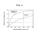
- FIG. 4 is a B-H curve diagram of the ring test pieces of Example 1 and Comparative Example 1.
- the first differential relative permeability ⁇ 'L is a value calculated by calculating a gradient ( ⁇ B/ ⁇ H) of a line connecting two points around an applied magnetic field of 100 A/m in the B-H curve of FIG. 4 and dividing this gradient by a space permeability
- the second differential relative permeability ⁇ 'H is a value calculated by calculating a gradient ( ⁇ B/ ⁇ H) of a line connecting two points around an applied magnetic field of 40 A/m in the B-H curve of FIG. 4 and dividing this gradient by a space permeability.
- ⁇ 'L/ ⁇ 'H is a value of the first differential relative permeability ⁇ 'L/the second differential relative permeability ⁇ 'H.
- Example 1 Comparative Example 1 First Differential Relative Permeability ⁇ 'L 45 151 Second Differential Relative Permeability ⁇ 'H 11.1 6.5 ⁇ 'L/ ⁇ 'H 4 23 Magnetic Flux Density (T) in Magnetic Field of 60 kA/m 1.33 1.95
- the ratio ⁇ 'L/ ⁇ 'H of the first differential relative permeability ⁇ 'L to the second differential relative permeability ⁇ 'H was about 1/6 of that of Comparative Example and was 10 or lower (specifically, 4). That is, it can be said that, in the dust core of Example 1, a decrease in differential relative permeability in a high magnetic field was suppressed as compared to the dust core of Comparative Example 1.
- the reason is presumed to be as follows.
- the powder for a dust core was used in which the soft magnetic particles were coated with the insulating film formed of aluminum oxide Al 2 O 3 . Therefore, during compression forming, the insulating film is less likely to flow as compared to that of Comparative Example 1 in which a silicone resin was used.
- the insulating film was secured between the soft magnetic particles. Therefore, it is considered that, even when the applied magnetic field was high, a decrease in differential relative permeability was suppressed.
- the magnetic flux density in an applied magnetic field of 60 kA/m was sufficiently high at 1.15 T which was equivalent to that of Comparative Example 1, and the first differential relative permeability ⁇ 'L was suppressed to be low.
- the second differential relative permeability ⁇ 'H was able to be maintained to be high, and the ratio ⁇ 'L/ ⁇ 'H of the first differential relative permeability ⁇ 'L to the second differential relative permeability ⁇ 'H was able to satisfy ⁇ 'L/ ⁇ 'H ⁇ 10.
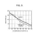
- a core of a reactor was prepared from each of the dust cores corresponding to Example 1 and Comparative Example 1. Using this core, a reactor shown in FIG. 9A was prepared. When a DC superimposed current was applied to the coil, the inductance of the reactor was measured. The results are shown in FIG. 5 . At this time, the gap width of the core (dust core), the measured inductance, the magnetic loss of the reactor, and the eddy-current loss of the coil were measured. The results are shown in Table 2. The current values in parentheses shown in Table 2 are current values flowing through the coil during the measurement.
- a ring test piece (dust core) was prepared using the same method as that of Example 1.
- Examples 3 to 5 were different from Example 1, in that, as shown in Table 3, a water-atomized power formed of an iron-silicon-aluminum alloy (Fe-2Si-4Al) containing 2 mass% of Si and 4 mass% of Al in addition to Fe was used as a soft magnetic powder constituting soft magnetic particles (base particles).
- Fe-2Si-4Al iron-silicon-aluminum alloy
- Example 4 was further different from Example 1, in that the forming surface pressure was changed to 8 t/cm 2 .
- Example 5 was further different from Example 1, in that the forming surface pressure was changed to 12 t/cm 2 .
- Example 7 was further different from Example 1, in that the heating time in an oxidizing atmosphere was changed to 120 minutes.
- the production conditions were the same as those of Example 1. Table 3 also shows the production conditions of Example 1 in order to clearly see the differences in production conditions between the ring test piece of Example 1 and the ring test pieces of Examples 2 to 7.
- a ring test piece (dust core) was prepared using the same method as that of Example 1.
- Comparative Examples 2 and 3 were different from Example 1, in that as shown in Table 4, iron-silicon alloy (Fe-3Si) powders having maximum particle sizes of 45 ⁇ m and 180 ⁇ m, which contained 3 mass% of Si in addition to Fe, were used as a soft magnetic powder constituting the base particles, 0.5 mass% of silicon resin was added to the powders, and soft magnetic particles were coated with this film at a film-forming temperature of 170°C for a film-forming time of 170 minutes to prepare powders for a dust core.
- Fe-3Si iron-silicon alloy
- Table 4 also shows the production conditions of Comparative Example 1 in order to clearly see the differences in production conditions between the dust core of Comparative Example 1 and the dust cores of Comparative Examples 2 and 3.
- Base Particles Maximum Particle Size of Base Material ( ⁇ m) Coating Conditions Forming Surface Pressure (t/cm 2 ) Density (g/cm 3 ) Content of Resin (mass%) Film-Forming Temperature (°C) Film-Forming Time (min) Comparative Example 1 Fe-3Si 180 0.5 130 130 16 7.25 Comparative Example 2 Fe-3Si 45 0.5 170 170 16 7.25 Comparative Example 3 Fe-3Si 180 0.5 170 170 16 7.30
- Comparative Example 4 As a soft magnetic powder constituting the soft magnetic particles, an iron-silicon alloy (Fe-6.5Si) powder containing 6.5 mass% of Si in addition to Fe was prepared, the soft magnetic powder was kneaded with a polyphenylene sulfide (PPS) resin such that the content of the PPS resin was 65 vol%, and the kneaded material was injected into the same size and the same shape as those of Example 1. As a result, a ring test piece was prepared.
- PPS polyphenylene sulfide
- Comparative Example 5 a ring test piece was prepared by injection molding using the same method as that of Comparative Example 4. Comparative Example 5 was different from Comparative Example 4, in that, as shown in Table 5, the soft magnetic powder was kneaded with a polyphenylene sulfide (PPS) resin such that the content of the PPS resin was 72 vol%.
- PPS polyphenylene sulfide
- Comparative Example 6 As a soft magnetic powder constituting the soft magnetic particles, an iron-silicon alloy (Fe-6.5Si) powder containing 6.5 mass% of Si in addition to Fe was prepared, the soft magnetic powder was kneaded with an epoxy resin such that the content of the epoxy resin was 60 vol%, the kneaded material was put into a forming die having the same size and the same shape as those of Example 1, and the epoxy resin was cured. As a result, a ring test piece was prepared.
- Fe-6.5Si iron-silicon alloy
- the magnetic flux density was measured by applying a magnetic current until 60 kA/m using the same method as that of Example 1.
- the first differential relative permeability ⁇ 'L in an applied magnetic field of 100 A/m, the second differential relative permeability ⁇ 'H in an applied magnetic field of 40 kA/m, and ⁇ 'L/ ⁇ 'H were calculated.
- ⁇ '24k/ ⁇ 'L was also calculated by measuring a first differential relative permeability ⁇ '24k in an applied magnetic field of 24 kA/m.
- the results are shown in Table 6.
- the magnetic flux density shown in Table 6 refers to the value in an applied magnetic field of 60 kA/m.
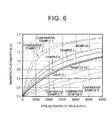
- FIG. 6 shows a relationship between an applied magnetic field and a magnetic flux density in each of the ring test pieces of Examples 1 to 7 and Comparative Examples 2 to 6.
- FIG. 7 shows a relationship between ⁇ 'L/ ⁇ 'H and a magnetic flux density B in an applied magnetic field of 60 kA/m in each of the ring test pieces of Examples 1 to 7 and Comparative Examples 1 to 6.
- Table 6 also shows the values of the first differential relative permeability ⁇ '24k in an applied magnetic field of 24 kA/m and ⁇ '24k/ ⁇ 'L.
- the magnetic characteristics of the dust core disclosed in JP 2002-141213 A are similar to those of Comparative Examples 4 to 6 of the present application and are clearly different from those of Examples 1 to 7.
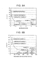
- FIG. 8A shows a relationship between ⁇ 'L/ ⁇ 'H and the ratio of the hardness of the insulating film of the powder for a dust core used in each of the ring test pieces of Examples 1 to 7 and Comparative Examples 1 to 3.
- FIG. 8B shows a relationship between ⁇ 'L/ ⁇ 'H and the thickness of the insulating film of the powder for a dust core used in each of the ring test pieces according to Examples 1 to 7 and Comparative Examples 1 to 3.
- the thickness of the insulating film is 150 nm or more under the condition of the above-described hardness ratio. It is considered that, by securing the thickness of the insulating film, the relationship of ⁇ '/L/ ⁇ 'H ⁇ 10 can be secured.
Landscapes
- Engineering & Computer Science (AREA)
- Chemical & Material Sciences (AREA)
- Power Engineering (AREA)
- Dispersion Chemistry (AREA)
- Mechanical Engineering (AREA)
- Materials Engineering (AREA)
- Metallurgy (AREA)
- Organic Chemistry (AREA)
- Manufacturing & Machinery (AREA)
- Physics & Mathematics (AREA)
- Electromagnetism (AREA)
- Soft Magnetic Materials (AREA)
Abstract
Description
- The present invention relates to a soft magnetic member having superior magnetic characteristics, a reactor using the soft magnetic member, a powder for a dust core, and a method of producing a dust core.
- In a hybrid vehicle, an electric vehicle, a solar power generation device, or the like, a reactor is used, and this reactor adopts a structure in which a coil is wound around a ring-shaped core which is a soft magnetic member. During use of the reactor, a wide range of currents flow through the coil. Therefore, at least 40 kA/m of magnetic field is applied to the core. In such an environment, it is necessary to stably secure the inductance of the reactor.
- In consideration of the above-described points, for example, a reactor 9 is disclosed in which, as shown in
FIG. 9A , a ring-shaped core 91 is divided intocore portions gap 93 is provided between the dividedcore portions coils 95A, 95B are wound around thecore 91 including this gap 93 (for example, refer to Japanese Patent Application Publication No.2009-296015 JP 2009-296015 A - According to the reactor 9, the
gap 93 is provided between the dividedcore portions - However, a soft magnetic member is used in a choke coil, an inductor, or the like. As such a soft magnetic member, a dust core is disclosed in which, when an initial magnetic permeability is represented by µ0 and a magnetic permeability in an applied magnetic field of 24 kA/m is represented by µ, a relationship of µ/µ0≥0.5 is satisfied between µ0 and µ (for example, refer to Japanese Patent Application Publication No.
2002-141213 JP 2002-141213 A - However, for example, in the technique disclosed in
JP 2009-296015 A FIG. 9B , a magnetic flux T is leaked in thegap 93 formed between the dividedcore portions - The problem which is described above using the reactor is an example. In equipment or an apparatus in which a magnetic field in a range from a low magnetic field to a high magnetic field (40 kA/m) is applied to a soft magnetic member, it is difficult to maintain the inductance, and typically a structural measure is taken.
- Even if a soft magnetic member having the characteristics disclosed in
JP 2002-141213 A - The invention provides a soft magnetic member, a reactor, a powder for a dust core, and a method of producing a dust core, in which a decrease in inductance can be suppressed even if an applied magnetic field is high (about 40 kA/m).
- As a result of a thorough study, the present inventors thought that, in order to suppress a decrease in inductance in a high magnetic field, it is important to secure a predetermined amount of magnetic flux density and to adjust a differential relative permeability to be high even in a high magnetic field. Therefore, the present inventors have focused on a ratio of a differential relative permeability in a specific low magnetic field to a differential relative permeability in a specific high magnetic field.
- According to a first aspect of the invention, there is provided a soft magnetic member, in which when a differential relative permeability in an applied magnetic field of 100 A/m is represented by a first differential relative permeability µ'L, and when a differential relative permeability in an applied magnetic field of 40 kA/m is represented by a second differential relative permeability µ'H, a ratio of the first differential relative permeability µ'L to the second differential relative permeability µ'H satisfies a relationship of µ'L/µ'H≤10, and a magnetic flux density in an applied magnetic field of 60 kA/m is 1.15 T or higher.
- In the soft magnetic member according to the aspect of the invention, the ratio of the first differential relative permeability µ'L to the second differential relative permeability µ'H satisfies a relationship of µ'L/µ'H≤10. As a result, the gradient of the B-H curve of the soft magnetic member can be secured to be large even in a high magnetic field, and the inductance of the soft magnetic member in a magnetic field of 40 kA/m can be maintained.
- Here, when µ'L/µ'H>10, a difference in differential relative permeability between a low magnetic field and a high magnetic field is increased. As a result, when a magnetic field is applied to a high magnetic field region, a decrease in inductance is increased. For example, when a core is divided into portions in a reactor, it is necessary that a gap between the divided portions be increased in order to maintain the inductance of the reactor. As a result, a leakage of a magnetic flux from the gap is increased, and this leaked magnetic flux intersects with the coil, which causes eddy-current loss in the core. It is preferable that µ'L/µ'H is low, and the lower limit thereof is 1. When µ'L/µ'H<1, it is difficult to produce a soft magnetic member.
- In addition, a magnetic flux density of 1.15 T or higher is secured in an applied magnetic field of 60 kA/m, and thus the inductance value can be maintained in a range from a low magnetic field to a high magnetic field. That is, when the magnetic flux density in an applied magnetic field of 60 kA/m is lower than 1.15 T, a decrease in inductance in a range from a low magnetic field to a high magnetic field is a concern. Therefore, this soft magnetic member is not sufficient for use in equipment such as a reactor. The upper limit of the magnetic flux density in an applied magnetic field of 60 kA/m is preferably 2.1 T. Since the saturated magnetic flux density of pure iron is about 2.2 T, it is difficult to produce a soft magnetic member having a magnetic flux density of more than 2.2 T.
- Here, "differential relative permeability" described herein is obtained by dividing a gradient of a tangent to a curve (B-H curve) between a magnetic field H and a magnetic flux density B by a space permeability, the curve being obtained by continuously applying a magnetic field. For example, a differential relative permeability in a magnetic field of 40 kA/m (second differential relative permeability µ'H) is obtained by dividing a gradient of a tangent to a B-H curve in a magnetic field of 40 kA/m by a space permeability.
- In the soft magnetic member according to the aspect of the invention, the soft magnetic member may be a dust core formed from a powder for the dust core; in the powder for the dust core, surfaces of soft magnetic particles may be coated with an insulating film; and the insulating film may have a Vickers hardness, which is 2.0 times or higher than that of the soft magnetic particles, and may have a thickness of 150 nm to 2 µm.
- As clearly seen from an experiment of the present inventors described below, when a compact as a dust core is formed, a material constituting the insulating film is not likely to be unevenly distributed in a boundary (triple point) between three particles of a powder for a dust core by adjusting the Vickers hardness and the thickness of the insulating film to be in the above-described ranges. As a result, after the formation of the compact, the distance between soft magnetic particles is secured, and a non-magnetic material as a material of the insulating film is maintained between the soft magnetic particles.
- In a dust core obtained by sintering the compact obtained as described above, the magnetic flux density during the application of a low magnetic field to the soft magnetic member can be decreased without decreasing the magnetic flux density in an applied magnetic field of 60 kA/m. That is, even when a magnetic field in a range from a low magnetic field (100 A/m) to a high magnetic field (40 kA/m) is applied to the dust core, a decrease in differential relative permeability in a high magnetic field can be suppressed. As a result, the inductance of the dust core in the above-described applied magnetic field range can be maintained.
- Here, when the Vickers hardness of the insulating film is lower than two times that of the soft magnetic particles, a material constituting the insulating film is likely to be unevenly distributed in a boundary (triple point) between three particles of a powder for a dust core during the formation of the powder. When the Vickers hardness of the insulating film is higher than 20 times that of the soft magnetic particles, the insulating film is too hard to compression-form a powder for a dust core.
- When the thickness of the insulating film is less than 150 nm, the distance between the soft magnetic particles cannot be sufficiently secured, which may increase µ'L/µ'H. On the other hand, when the thickness of the insulating film exceeds 2 µm, an occupancy of a non-magnetic component (insulating film) increases, and thus it is difficult to satisfy a relationship in which the magnetic flux density in an applied magnetic field of 60 kA/m is 1.15 T or higher.
- Further, in the above-described aspect, the soft magnetic particles may be formed of an iron-aluminum-silicon alloy, and the insulating film may contain aluminum oxide as a major component. By selecting such a material, the above-described relationship of µ'L/µ'H≤10 is satisfied, and the condition where the magnetic flux density in an applied magnetic field of 60 kA/m is 1.15 T or higher is likely to be satisfied.
- In particular, when aluminum of the soft magnetic particles formed of an iron-aluminum-silicon alloy is preferentially oxidized by oxidizing gas having a predetermined gas ratio, the above-described hardness relationship and the above-described thickness range can be easily satisfied.
- According to a second aspect of the invention, there is provided a reactor. The reactor includes: a core formed of the above-described dust core; and a coil that is wound around the core. In such a reactor, even when a current in a range from a low current to a high current flows through the coil, the inductance is maintained. Therefore, the core is not necessarily divided, or even if the core is divided into portions, a gap between the divided portions can be reduced. As a result, eddy-current loss of the coil due to a leaked magnetic flux can be removed or decreased.
- Further, according to a third aspect of the invention, there is provided a powder for a dust core which is suitable for the above-described dust core. In the powder for the dust core according to the third aspect of the invention, surfaces of soft magnetic particles may be coated with an insulating film, and the insulating film may have a Vickers hardness, which is 2.0 times or higher than that of the soft magnetic particles, and may have a thickness of 150 nm to 2 µm.
- By using the powder for a dust core, the relationship of µ'L/µ'H≤10 can be satisfied, and a powder for a dust core having an magnetic flux density of 1.15 T or higher in an applied magnetic field of 60 kA/m can be easily produced.
- In the above-described aspect, the soft magnetic particles may be formed of an iron-aluminum-silicon alloy, and the insulating film may contain aluminum oxide as a major component. In particular, when aluminum of the soft magnetic particles formed of an iron-aluminum-silicon alloy is preferentially oxidized by oxidizing gas having a predetermined gas ratio, the above-described hardness relationship and the above-described thickness range can be easily satisfied.
- According to a fourth aspect of the invention, there is provided a method of producing a dust core including: forming a green compact from the powder for the dust core according to the above-described aspect of the invention, and; sintering the green compact. As a result, a dust core having the above-described characteristics can be obtained.
- According to the above-described aspects of the invention, even when the applied magnetic field is high (about 40 kA/m), a decrease in inductance can be suppressed.
- Features, advantages, and technical and industrial significance of exemplary embodiments of the invention will be described below with reference to the accompanying drawings, in which like numerals denote like elements, and wherein:
-
FIGS. 1A to 1C are schematic diagrams showing a method of producing a soft magnetic member (dust core) according to an embodiment of the invention, in whichFIG. 1A is a diagram showing soft magnetic particles,FIG. 1B is a diagram showing particles constituting a powder for a dust core, andFIG. 1C is a diagram showing a particle state in a compact; -
FIGS. 2A to 2D are schematic diagrams showing a method of producing a soft magnetic member (dust core) of the related art, in whichFIG. 2A is a diagram showing soft magnetic particles,FIG. 2B is a diagram showing particles constituting a powder for a dust core,FIG. 2C is a diagram showing a particle state in a compact, andFIG. 2D is an enlarged image showing a dust core produced using the method of the related art; -
FIG. 3A is a diagram showing a relationship between an applied magnetic field and a magnetic flux density in each ofConventional Product 1 andConventional Product 2 in which the amount of a resin is more than that ofConventional Product 1; -
FIG. 3B is a diagram showing a relationship between an applied magnetic field and a magnetic flux density in each ofConventional Product 1 and a product of the invention; -
FIG. 4 is a B-H curve diagram showing ring test pieces of Example 1 and Comparative Example 1; -
FIG. 5 is a diagram showing a relationship between an inductance and a DC superimposed current in each of reactors of Example 1 and Comparative Example 1; -
FIG. 6 is a B-H curve diagram showing ring test pieces of Examples 1 to 7 and Comparative Examples 2 to 6; -
FIG. 7 is a diagram showing a relationship between µ'L/µ'H and a magnetic flux density B in an applied magnetic field of 60 kA/m in each of ring test pieces of Examples 1 to 7 and Comparative Examples 1 to 6; -
FIG. 8A is a diagram showing a relationship between µ'L/µ'H and a ratio of the hardness of an insulating film of a powder for a dust core used in each of the ring test pieces of Examples 1 to 7 and Comparative Examples 1 to 3; -
FIG. 8B is a diagram showing a relationship between µ'L/µ'H and the thickness of the insulating film of the powder for a dust core used in each of the ring test pieces of Examples 1 to 7 and Comparative Examples 1 to 3; and -
FIG. 9A is a schematic diagram showing a reactor of the related art; -
FIG. 9B is an enlarged view showing major components of the reactor inFIG. 9A . - Hereinafter, an embodiment of a powder for a dust core according to the invention and a soft magnetic member formed from the powder will be described with reference to the drawings.
-
FIGS. 1A to 1C are schematic diagrams showing a method of producing a soft magnetic member (dust core) according to an embodiment of the invention, in whichFIG. 1A is a diagram showing soft magnetic particles,FIG. 1B is a diagram showing particles constituting a powder for a dust core, andFIG. 1C is a diagram showing a particle state in a compact; - As shown in
FIG. 1B , thepowder 10 for a dust core according to the embodiment is an aggregate ofparticles 13 for a dust core. Theparticles 13 for a dust core include: softmagnetic particles 11 formed of a soft magnetic material; and an insulatingfilm 12 formed of a non-magnetic material, in which surfaces of the softmagnetic particles 11 are coated with the insulatingfilm 12, and the insulating film has a hardness, which is 2 times or higher than that of the softmagnetic particles 11, and has a thickness of 150 nm to 2 µm. - The average particle size of particles (on which the insulating film is formed) constituting the
powder 10 for a dust core is preferably 5 µm to 500 µm and more preferably 20 µm to 450 µm. By using the soft magnetic powder having an average particle size in the above-described range, a dust core having superior insulating properties can be obtained. When the average particle size is less than 20 µm, a ratio of an insulating material constituting the insulating film is increased, which decreases the saturated magnetic flux density On the other hand, when the average particle size is more than 450 µm, a ratio of an insulating material constituting the insulating film is decreased, and it is difficult to obtain desired magnetic characteristics and desired insulating properties (specific resistance). When the average particle size is more than 500 µm, it is difficult to obtain insulating properties, and the eddy current of the particles (powder) is increased, and the loss is increased. - A method of producing the
powder 10 for a dust core will be described below. First, as shown inFIG. 1A , as the soft magnetic material constituting the soft magnetic particles (base particles) 11, for example, iron, cobalt, or nickel is prepared. More preferably, an iron-based material may be used, and examples thereof include iron (pure iron), an iron-silicon alloy, an iron-nitrogen alloy, an iron-nickel alloy, an iron-carbon alloy, an iron-boron alloy, an iron-cobalt alloy, an iron-phosphorus alloy, an iron-nickel-cobalt alloy, and an iron-aluminum-silicon alloy. - Examples of the soft magnetic powder formed of the soft
magnetic particles 11 include water-atomized powder, gas-atomized powder, and pulverized powder.From the viewpoint of suppressing a destruction of an insulating layer during press forming, it is more preferable to select a powder having a small amount of convexo-concave portions on particle surfaces. - When the above-described metals are selected as the soft magnetic material constituting the soft
magnetic particles 11, for example, iron oxide (Fe3O4, Fe2O3), iron nitride, silicon oxide (SiO2), or silicon nitride (Si3O4) can be used as the material of the insulatingfilm 12 under the condition that the above-described thickness range and the above-described hardness relationship of the film are satisfied. As another conditions, it is necessary that the formed dust core satisfy a relationship of µ'L/µ'H≤10 described below and satisfy a magnetic flux density of 1.15 T or higher in an applied magnetic field of 60 kA/m. - In addition, the insulating
film 12 can be formed on the softmagnetic particles 11 by oxidizing the surfaces of the softmagnetic particles 11 shown inFIG. 1A . As another method, the above-described material constituting the insulating film may be attached on the surfaces of the softmagnetic particles 11 shown inFIG. 1A using PVD, CVD, or the like. - In the embodiment, an iron-aluminum-silicon alloy is used as the soft magnetic material constituting the soft
magnetic particles 11. The softmagnetic particles 11 formed of the metal alloy are oxidized by being heated using a mixed oxidizing gas containing nitrogen gas and oxygen gas at a predetermined ratio, the gases being supplied from industrial gas cylinders. At this time, aluminum is dispersed and compressed on the surfaces of the softmagnetic particles 11, and aluminum is preferentially oxidized. - As a result, a film containing aluminum oxide having a high purity as a major component (containing aluminum oxide and unavoidable impurities) can be formed. Aluminum oxide has higher hardness and insulating properties than those of other materials, is superior in heat resistance, and is highly stable to a chemical solution such as a coolant. As a result, the insulating
film 12 formed of aluminum oxide, which has a hardness two times or higher than that of the softmagnetic particles 11 and has a thickness of 150 nm to 2 µm, can be easily obtained. - Here, in the iron-aluminum-silicon alloy, it is preferable that the Si content is 1 mass% to 7 mass%, the Al content is 1 mass% to 6 mass%, the total content of Si and Al is 1 mass% to 12 mass%, and the balance includes iron and unavoidable impurities.
- Here, when the contents of Si and Al are lower than the above-described ranges, it is difficult to produce aluminum oxide, other oxides are produced, and thus magnetic loss increases. In addition, when the Si content exceeds the above-described range, the plastic deformation resistance of the powder for a dust core increases, and the formability into a dust core deteriorates. Therefore, the saturated magnetic flux density decreases. In addition, when the total content of Si and Al exceeds the above-described range, or when the Al content exceeds the above-described range, a ratio of iron in the soft magnetic particles decreases, and the saturated magnetic flux density decreases.
- As shown in
FIG. 1C , the powder for a dust core is compression-formed into a green compact, and this green compact is annealed by a heat treatment. As a result, adust core 1 can be obtained. At this time, the insulatingfilm 12, which has a hardness two times or higher than that of the softmagnetic particles 11 and has a thickness of 150 nm to 2 µm, is provided. Therefore, the material (non-magnetic material) constituting the insulatingfilm 12 is not likely to be distributed in a boundary 14 (triple point) between threeparticles magnetic particles film 12 is maintained between the soft magnetic particles. - In the related art, as shown in
FIG. 2B , apowder 80 for a dust core formed ofparticles 83 for a dust core is used, in which surfaces of softmagnetic particles 81 are coated with a soft insulatingfilm 82 formed of a silicone resin or the like. When a magnetic field in a range from a low magnetic field to a high magnetic field is applied to adust core 8 ofFIG. 2C produced using thepowder 80 for a dust core, in a high magnetic field (exceeding 40 kA/m), the magnetic flux density approaches the saturated magnetic flux density, and the differential relative permeability decreases. - The inductance L of the dust core (reactor) is represented by L=n·S·µ' (wherein n: the winding number of the coil, S: the cross-sectional area of a portion of the dust core around which the core is wound, µ': the differential relative permeability). In order to maintain characteristics of the inductance L in a high magnetic field, it is important to suppress a decrease in differential relative permeability in a high magnetic field.
- Here, the magnetic field H applied to the dust core is represented by H=n·I/L (wherein n: the winding number of the coil, I: the current flowing through the coil, L: the magnetic path length of the dust core), in which the current I flowing through the coil is proportional to the applied magnetic field H. Accordingly, in the dust core 8 (Conventional Product 1) shown in
FIG. 3A , in order to suppress a decrease in differential relative permeability in a high magnetic field, a decrease in differential relative permeability in a low magnetic field is effective. - Therefore, in
Conventional Product 1, when the thickness of the insulatingfilm 82 shown inFIG. 2B is increased (when a ratio of a resin is increased), the differential relative permeability in a low magnetic field can be decreased by increasing the content of the resin as a non-magnetic component. However, inConventional Product 2 ofFIG. 3A , the saturated magnetic flux density in a high magnetic field is decreased. - One of the reasons is presumed to be as follows: as shown in
FIG. 2C , a material (non-magnetic material) constituting the insulatingfilm 82 is unevenly distributed in the boundary (triple point) 84 between threeparticles powder 80 for a dust core. As shown inFIG. 2D , the uneven distribution of the resin in the triple point was verified from an experiment of the present inventors. - From this point of view, it can be considered that, by providing a gap in Conventional Product 1 (core) as shown in
FIG. 9A , the magnetic flux density in a low magnetic field can be decreased, and a decrease in differential relative permeability in a high magnetic field can be decreased as shown in Conventional Product 1 (gap provided) ofFIG. 3B . However, when such a gap is provided, a leakage of a magnetic flux T from the gap is increased as shown inFIG. 9B , this leaked magnetic flux intersects with the coil, which causes eddy-current loss in the core. - In the embodiment, the hardness and the thickness of the insulating
film 12 shown inFIG. 1B are adjusted to be in the above-described ranges. As a result, when a compact as thedust core 1 is formed, the material (non-magnetic material) constituting the insulatingfilm 12 is not likely to be unevenly distributed in the boundary (triple point) 14 between three particles of thepowder 10 for a dust core. As a result, after the formation of the compact, the distance between the softmagnetic particles film 12 is maintained between the soft magnetic particles. - In the
dust core 1 obtained by sintering the compact obtained as described above, when a differential relative permeability in an applied magnetic field of 100 A/m is represented by a first differential relative permeability µ'L, and when a differential relative permeability in an applied magnetic field of 40 kA/m is represented by a second differential relative permeability µ'H, a ratio of the first differential relative permeability µ'L to the second differential relative permeability µ'H satisfies a relationship of µ'L/µ'H≤10, and a magnetic flux density in an applied magnetic field of 60 kA/m is 1.15 T or higher. - As a result, as shown in a product of the invention of
FIG. 3B , even when a magnetic field in a range from a low magnetic field (100 A/m) to a high magnetic field (40 kA/m) is applied to the dust core, a decrease in differential relative permeability in a high magnetic field can be suppressed. As a result, the inductance of the dust core (reactor) in the above-described applied magnetic field range can be maintained. - In the embodiment, as shown in
FIG. 9A , unlike the techniques of the related art, it is not necessary to provide a large gap between divided core portions. Therefore, a leakage of the magnetic flux in a reactor can be suppressed. - Hereinafter, the invention will be described using Examples.
- As a soft magnetic powder constituting soft magnetic particles, a water-atomized power (maximum particle size: 75 µm; measured using a measured sieve defined according to JIS-Z8801) formed of an iron-silicon-aluminum alloy (Fe-5Si-4Al) containing 5 mass% of Si and 4 mass% of Al in addition to Fe was prepared.
- Next, the water-atomized powder was heated at 900°C for 300 minutes in an atmosphere of a mixed oxidizing gas containing 20 vol% of oxygen gas and 80 vol% of nitrogen gas, the gases being supplied from industrial gas cylinders. As a result, surfaces of the soft magnetic particles were coated with a film formed of aluminum oxide (Al2O3) having a thickness of 460 nm as an insulating film. The formation of aluminum oxide was measured using XRD analysis, and the thickness was measured using Auger spectroscopy analysis (AES).
- The powder for a dust core is put into a die, and a ring-shaped green compact having an outer diameter of 39 mm, an inner diameter of 30 mm, and a thickness of 5 mm was prepared using a die lubrication warm forming method under conditions of a forming temperature of 130°C and a forming pressure of 16 t/cm2. The formed green compact was heat-treated (sintered) in a nitrogen atmosphere at 750°C for 30 minutes. As a result, a ring test piece (dust core) was prepared.
- A ring test piece (dust core) was prepared using the same method as that of Example 1. Comparative Example 1 was different from Example 1, in that an iron-silicon alloy (Fe-3Si) powder containing 3 mass% of Si in addition to Fe was used as a soft magnetic powder constituting the soft magnetic particles, 0.5 mass% of silicone resin was added to the powder, and soft magnetic particles were coated with this film at a film-forming temperature of 130°C for a film-forming time of 130 minutes to prepare a powder for a dust core.
- Using an Autograph, coils were wound around each of the ring test pieces prepared in Example 1 and Comparative Example 1 under conditions of a winding number of 450 turns on an excitation side and 90 turns on a detection side. Next, by causing a current to flow through the coil, a magnetic field was applied so as to linearly increase from 0 kA/m to 60 kA/m. At this time, the magnetic flux density was measured using a DC magnetic flux meter. The results are shown in
FIG. 4. FIG. 4 is a B-H curve diagram of the ring test pieces of Example 1 and Comparative Example 1. - From the obtained graph (B-H curve diagram) showing the applied magnetic field and the magnetic flux density, the first differential relative permeability µ'L in an applied magnetic field of 100 A/m, the second differential relative permeability µ'H in an applied magnetic field of 40 kA/m, and µ'L/µ'H were calculated. The results are shown in Table 1. In addition, regarding each of the ring test pieces of Example 1 and Comparative Example 1, the magnetic flux density in an applied magnetic field of 60 kA/m was measured. The results are shown in Table 1.
- Specifically, the first differential relative permeability µ'L is a value calculated by calculating a gradient (ΔB/ΔH) of a line connecting two points around an applied magnetic field of 100 A/m in the B-H curve of
FIG. 4 and dividing this gradient by a space permeability Likewise, the second differential relative permeability µ'H is a value calculated by calculating a gradient (ΔB/ΔH) of a line connecting two points around an applied magnetic field of 40 A/m in the B-H curve ofFIG. 4 and dividing this gradient by a space permeability. µ'L/µ'H is a value of the first differential relative permeability µ'L/the second differential relative permeability µ'H.[Table 1] Example 1 Comparative Example 1 First Differential Relative Permeability µ'L 45 151 Second Differential Relative Permeability µ'H 11.1 6.5 µ'L/ µ'H 4 23 Magnetic Flux Density (T) in Magnetic Field of 60 kA/m 1.33 1.95 - As shown in Table 1, in the ring test piece (dust core) of Example 1, the ratio µ'L/µ'H of the first differential relative permeability µ'L to the second differential relative permeability µ'H was about 1/6 of that of Comparative Example and was 10 or lower (specifically, 4). That is, it can be said that, in the dust core of Example 1, a decrease in differential relative permeability in a high magnetic field was suppressed as compared to the dust core of Comparative Example 1.
- The reason is presumed to be as follows. In the dust core of Example 1, the powder for a dust core was used in which the soft magnetic particles were coated with the insulating film formed of aluminum oxide Al2O3. Therefore, during compression forming, the insulating film is less likely to flow as compared to that of Comparative Example 1 in which a silicone resin was used. As a result, in the dust core of Example 1, as compared to that of Comparative Example 1, the insulating film was secured between the soft magnetic particles. Therefore, it is considered that, even when the applied magnetic field was high, a decrease in differential relative permeability was suppressed.
- In addition, in the dust core of Example 1, the magnetic flux density in an applied magnetic field of 60 kA/m was sufficiently high at 1.15 T which was equivalent to that of Comparative Example 1, and the first differential relative permeability µ'L was suppressed to be low. As a result, it is considered that the second differential relative permeability µ'H was able to be maintained to be high, and the ratio µ'L/µ'H of the first differential relative permeability µ'L to the second differential relative permeability µ'H was able to satisfy µ'L/µ'H≤10.
- Further, a core of a reactor was prepared from each of the dust cores corresponding to Example 1 and Comparative Example 1. Using this core, a reactor shown in
FIG. 9A was prepared. When a DC superimposed current was applied to the coil, the inductance of the reactor was measured. The results are shown inFIG. 5 . At this time, the gap width of the core (dust core), the measured inductance, the magnetic loss of the reactor, and the eddy-current loss of the coil were measured. The results are shown in Table 2. The current values in parentheses shown in Table 2 are current values flowing through the coil during the measurement.[Table 2] Example 1 Comparative Example 1 Inductance L (at 10 A) 174 µH 165 µH Inductance L (at 100 A) 128 µH 138 µH Inductance L (at 200 A) 90 µH 73 µH Gap Length 1.8 mm 2.4 mm Magnetic Loss (at 50 A) 102 W 128 W Eddy-Current Loss of Coil 24 W 40 W - As shown in
FIG. 5 and Table 2, in the reactor of Example 1, although the gap length was shorter than that of Comparative Example 1 by 0.6 mm (decrease by 25%), the inductance value was higher than that of Comparative Example 1 even in a high current region of 150 A or higher (that is, in a high magnetic field). That is, as shown in Table 1, it can be said that, in the dust core of Example 1, a decrease in differential relative permeability in a high magnetic field was suppressed as compared to the dust core of Comparative Example 1. - In addition, as shown in Table 2, in the reactor of Example 1, the gap length of the core was shorter than that of Comparative Example 1. As a result, it is considered that the leakage of the magnetic flux between the core portions shown in
FIG. 9B was decreased, and the magnetic loss and the eddy-current loss of the coil were decreased. - A ring test piece (dust core) was prepared using the same method as that of Example 1. Examples 3 to 5 were different from Example 1, in that, as shown in Table 3, a water-atomized power formed of an iron-silicon-aluminum alloy (Fe-2Si-4Al) containing 2 mass% of Si and 4 mass% of Al in addition to Fe was used as a soft magnetic powder constituting soft magnetic particles (base particles).
- In addition, Example 4 was further different from Example 1, in that the forming surface pressure was changed to 8 t/cm2. Example 5 was further different from Example 1, in that the forming surface pressure was changed to 12 t/cm2. Example 7 was further different from Example 1, in that the heating time in an oxidizing atmosphere was changed to 120 minutes. In Examples 2 and 6, the production conditions were the same as those of Example 1. Table 3 also shows the production conditions of Example 1 in order to clearly see the differences in production conditions between the ring test piece of Example 1 and the ring test pieces of Examples 2 to 7.
[Table 3] Base Particles Maximum Particle Size of Base Material (µm) Oydizing Conditions Forming Surface Pressure (t/cm2) Density (g/cm3) Temperature (°C) Time (min) Example 1 Fe-5Si-4Al 75 900 300 16 6.20 Example 2 Fe-5Si-4Al 75 900 300 16 6.21 Example 3 Fe-2Si-4Al 75 900 300 16 6.79 Example 4 Fe-2Si-4Al 75 900 300 8 6.21 Example 5 Fe-2Si-4Al 75 900 300 12 6.57 Example 6 Fe-5Si-4Al 75 900 300 16 6.19 Example 7 Fe-5Si-4Al 75 900 120 16 6.20 - A ring test piece (dust core) was prepared using the same method as that of Example 1. Comparative Examples 2 and 3 were different from Example 1, in that as shown in Table 4, iron-silicon alloy (Fe-3Si) powders having maximum particle sizes of 45 µm and 180 µm, which contained 3 mass% of Si in addition to Fe, were used as a soft magnetic powder constituting the base particles, 0.5 mass% of silicon resin was added to the powders, and soft magnetic particles were coated with this film at a film-forming temperature of 170°C for a film-forming time of 170 minutes to prepare powders for a dust core. Table 4 also shows the production conditions of Comparative Example 1 in order to clearly see the differences in production conditions between the dust core of Comparative Example 1 and the dust cores of Comparative Examples 2 and 3.
[Table 4] Base Particles Maximum Particle Size of Base Material (µm) Coating Conditions Forming Surface Pressure (t/cm2) Density (g/cm3) Content of Resin (mass%) Film-Forming Temperature (°C) Film-Forming Time (min) Comparative Example 1 Fe-3Si 180 0.5 130 130 16 7.25 Comparative Example 2 Fe-3Si 45 0.5 170 170 16 7.25 Comparative Example 3 Fe-3Si 180 0.5 170 170 16 7.30 - In Comparative Example 4, as shown in Table 5, as a soft magnetic powder constituting the soft magnetic particles, an iron-silicon alloy (Fe-6.5Si) powder containing 6.5 mass% of Si in addition to Fe was prepared, the soft magnetic powder was kneaded with a polyphenylene sulfide (PPS) resin such that the content of the PPS resin was 65 vol%, and the kneaded material was injected into the same size and the same shape as those of Example 1. As a result, a ring test piece was prepared.
- In Comparative Example 5, a ring test piece was prepared by injection molding using the same method as that of Comparative Example 4. Comparative Example 5 was different from Comparative Example 4, in that, as shown in Table 5, the soft magnetic powder was kneaded with a polyphenylene sulfide (PPS) resin such that the content of the PPS resin was 72 vol%.
- In Comparative Example 6, as shown in Table 5, as a soft magnetic powder constituting the soft magnetic particles, an iron-silicon alloy (Fe-6.5Si) powder containing 6.5 mass% of Si in addition to Fe was prepared, the soft magnetic powder was kneaded with an epoxy resin such that the content of the epoxy resin was 60 vol%, the kneaded material was put into a forming die having the same size and the same shape as those of Example 1, and the epoxy resin was cured. As a result, a ring test piece was prepared.
[Table 5] Base Particles Coating Conditions Density (g/cm3) Resin Content (vol%) Comparative Example 4 Fe-6.5Si PPS 65 5.29 Comparative Example 5 Fe-6.5Si PPS 72 5.71 Comparative Example 6 Fe-6.5 Si Epoxy 60 4.93 - Regarding each of the ring test pieces of Examples 1 to 7 and Comparative Examples 1 to 6, the weight was measured, and the density was measured from the volume during the formation. The results are shown in the respective items of Tables 3 to 5. In the ring test pieces of Comparative Examples 4 to 6, the content of the resin was high, and thus the density was lower than that of Examples 1 to 7 and Comparative Examples 1 to 3.
- Regarding each of the ring test pieces of Examples 2 to 7 and Comparative Examples 2 to 6, the magnetic flux density was measured by applying a magnetic current until 60 kA/m using the same method as that of Example 1. The first differential relative permeability µ'L in an applied magnetic field of 100 A/m, the second differential relative permeability µ'H in an applied magnetic field of 40 kA/m, and µ'L/µ'H were calculated. Further, µ'24k/µ'L was also calculated by measuring a first differential relative permeability µ'24k in an applied magnetic field of 24 kA/m. The results are shown in Table 6. The magnetic flux density shown in Table 6 refers to the value in an applied magnetic field of 60 kA/m.
- Using the above results,
FIG. 6 shows a relationship between an applied magnetic field and a magnetic flux density in each of the ring test pieces of Examples 1 to 7 and Comparative Examples 2 to 6.FIG. 7 shows a relationship between µ'L/µ'H and a magnetic flux density B in an applied magnetic field of 60 kA/m in each of the ring test pieces of Examples 1 to 7 and Comparative Examples 1 to 6.[Table 6] Magnetic Flux Density B (T) µ'L µ'H µ'L/µ'H µ'24k µ'24k/µ'L Example 1 1.33 45 11.1 4 18 0.40 Example 2 1.29 41 10.9 4 18 0.43 Example 3 1.63 77 10.2 8 18 0.24 Example 4 1.35 48 10.4 5 17 0.35 Example 5 1.50 60 10.6 6 18 0.30 Example 6 1.30 40 10.9 4 18 0.44 Example 7 1.30 40 10.8 4 18 0.45 Comparative Example 1 1.95 151 6.5 23 14 0.09 Comparative Example 2 2.14 210 6.6 20 14 0.11 Comparative Example 3 2.16 32 5.9 32 13 0.07 Comparative Example 4 0.84 2 16 2 12 0.71 Comparative Example 5 1.03 2 22 2 14 0.64 Comparative Example 6 0.96 2 22 2 13 0.62 - As shown in Table 6 and
FIGS. 6 and7 , in the ring test pieces of Comparative Examples 4 to 6, the content of the resin is high, and thus the distance between the soft magnetic particles was increased. As a result, it is considered that the resin was present between the soft magnetic particles, and thus the magnetic flux density in an applied magnetic field of 60 kA/m was lower than that of Examples 1 to 7 and Comparative Examples 1 to 3. - In addition, regarding each of the ring test pieces of Examples 1 to 7 and Comparative Examples 1 to 3, the magnetic flux density in an applied magnetic field of 60 kA/m was secured to be 1.15 or higher. However, in the ring test pieces of Comparative Examples 1 to 3, µ'L/µ'H exceeded 10 unlike in Examples 1 to 7. Therefore, as shown in
Result 2, a decrease in differential relative permeability in a high magnetic field is more concerned as compared to Examples 1 to 7. - For a comparison to the technique disclosed in
JP 2002-141213 A JP 2002-141213 A JP 2002-141213 A - In the powder for a dust core used in each of the ring test pieces of Examples 1 to 7 and Comparative Examples 1 to 3, the hardness of the soft magnetic particles (base material) and the hardness of the insulating film were measured. Specifically, these materials were treated under the same conditions as shown in Tables 3 to 5 to prepare blocks, respectively. By measuring the hardness of each block using a micro-Vickers hardness meter, the hardness of the soft magnetic particle (base material) and the hardness of the insulating film was obtained. Further, a ratio of the above harnesses (the Vickers hardness of the insulating film/the Vickers hardness of the base material) was calculated. The results are shown in Table 7. Table 7 also shows the magnetic flux density B (T) in an applied magnetic field of 60 kA/m and µ'L/µ'H shown in Table 6.
- In the powder for a dust core used in each of the ring test pieces of Examples 2 to 7 and Comparative Example 1 to 3, the thickness of the insulating film was measured using the same method as that of Example 1. The results are shown in Table 7.
- Using the above results,
FIG. 8A shows a relationship between µ'L/µ'H and the ratio of the hardness of the insulating film of the powder for a dust core used in each of the ring test pieces of Examples 1 to 7 and Comparative Examples 1 to 3.FIG. 8B shows a relationship between µ'L/µ'H and the thickness of the insulating film of the powder for a dust core used in each of the ring test pieces according to Examples 1 to 7 and Comparative Examples 1 to 3.[Table 7] Magnetic Flux Density B (T) µ'L/µ'H Hardness Ratio Hardness of Base Material (Hv) Hardness of Insulating Film (Hv) Thickness (µm) Example 1 1.33 4 3.5 400 1400 500 Example 2 1.29 4 3.5 400 1400 500 Example 3 1.63 8 8 180 1400 400 Example 4 1.35 5 8 180 1400 400 Example 5 1.50 6 8 180 1400 400 Example 6 1.30 4 3.5 400 1400 400 Example 7 1.30 4 3.5 400 1400 200 Comparative Example 1 1.95 23 0.16 190 30 30 Comparative Example 2 2.14 20 0.23 190 30 30 Comparative Example 3 2.16 32 0.23 190 30 30 - As shown in Table 7 and
FIG. 8A , when the powders for a dust core of Examples 1 to 7 were used, the µ'L/µ'H values of the ring test pieces were 10 or lower. When the powders for a dust core of Comparative Examples 1 to 3 were used, the µ'L/µ'H values of the ring test pieces were 20 or higher. - The reason is considered to be as follows: since the insulating film of each of the powders for a dust core of Examples 1 to 7 was significantly harder than the soft magnetic powder as the base material, and thus the insulating film was held between the soft magnetic particles during compression forming without being moved. On the other hand, in each of Comparative Examples 1 to 3, the hardness of the insulating film was equivalent to that of the soft magnetic powder as the base material. Therefore, as shown in
FIG. 2D , the insulating film was compressed at a triple point of a boundary of the soft magnetic powder. Therefore, it is considered that the µ'L/µ'H values of the ring test pieces were higher than those of Examples 1 to 7. In Table 7, the hardness of the base material and the hardness of the insulating film of Comparative Example 1 were the same as those of Comparative Examples 2 and 3, but the hardness ratios thereof were different from each other. This result is caused by significant digits. - It is presumed from the above results that, when the insulating film has a Vickers hardness which is 1.5 times or higher than that of the soft magnetic particles as shown in
FIG. 8B , during compression forming, the movement of the insulating film to the triple point between the soft magnetic particles can be suppressed, and the relationship of µ'L/µ'H≤10 can be satisfied. - Further, in order to secure the above-described characteristics, as shown in Table 7 and
FIG. 8 , it is preferable that the thickness of the insulating film is 150 nm or more under the condition of the above-described hardness ratio. It is considered that, by securing the thickness of the insulating film, the relationship of µ'/L/µ'H≤10 can be secured. - Hereinabove, the embodiment of the invention has been described. However, a specific configuration is not limited to the embodiment, and design changes and the like which are made within a range not departing from the scope of the invention are included in the invention.
Claims (7)
- A soft magnetic member characterized in that
the soft magnetic member is formed such that, when a differential relative permeability in an applied magnetic field of 100 A/m is represented by a first differential relative permeability µ'L, and when a differential relative permeability in an applied magnetic field of 40 kA/m is represented by a second differential relative permeability µ'H, a ratio of the first differential relative permeability µ'L to the second differential relative permeability µ'H satisfies a relationship of µ'L/µ'H≤10, and a magnetic flux density in an applied magnetic field of 60 kA/m is 1.15 T or higher. - The soft magnetic member according to claim 1, characterized in that
the soft magnetic member is a dust core (1) formed from a powder for a dust core (10),
in the powder for the dust core, surfaces of soft magnetic particles (11) are coated with an insulating film (2), and
the insulating film has a Vickers hardness, which is 2.0 times or higher than that of the soft magnetic particles, and has a thickness of 150 nm to 2 µm. - The soft magnetic member according to claim 2, characterized in that
the soft magnetic particles are formed of an iron-aluminum-silicon alloy, and
the insulating film contains aluminum oxide as a major component. - A reactor characterized by comprising:a core formed of the dust core that is the soft magnetic member according to claim 2 or 3; anda coil that is wound around the core.
- A powder for a dust core (10) characterized in that
in the powder for the dust core, surfaces of soft magnetic particles (11) are coated with an insulating film (2), and
the insulating film has a Vickers hardness, which is 2.0 times or higher than that of the soft magnetic particles, and has a thickness of 150 nm to 2 µm. - The powder for the dust core according to claim 5 characterized in that
the soft magnetic particles are formed of an iron-aluminum-silicon alloy, and
the insulating film contains aluminum oxide as a major component. - A method of producing a dust core, the method characterized by comprising:forming a green compact from the powder for the dust core according to claim 5 or 6, and;sintering the green compact.
Applications Claiming Priority (1)
| Application Number | Priority Date | Filing Date | Title |
|---|---|---|---|
| JP2014122429A JP6243298B2 (en) | 2014-06-13 | 2014-06-13 | Powder magnetic core and reactor |
Publications (3)
| Publication Number | Publication Date |
|---|---|
| EP2963659A1 true EP2963659A1 (en) | 2016-01-06 |
| EP2963659A8 EP2963659A8 (en) | 2016-03-09 |
| EP2963659B1 EP2963659B1 (en) | 2019-07-24 |
Family
ID=53404392
Family Applications (1)
| Application Number | Title | Priority Date | Filing Date |
|---|---|---|---|
| EP15171922.6A Active EP2963659B1 (en) | 2014-06-13 | 2015-06-12 | Soft magnetic member and reactor |
Country Status (4)
| Country | Link |
|---|---|
| US (1) | US9941039B2 (en) |
| EP (1) | EP2963659B1 (en) |
| JP (1) | JP6243298B2 (en) |
| CN (1) | CN105280322B (en) |
Families Citing this family (8)
| Publication number | Priority date | Publication date | Assignee | Title |
|---|---|---|---|---|
| WO2016039267A1 (en) | 2014-09-08 | 2016-03-17 | トヨタ自動車株式会社 | Dust core, powder for magnetic cores, method for producing dust core, and method for producing powder for magnetic cores |
| JP6378156B2 (en) | 2015-10-14 | 2018-08-22 | トヨタ自動車株式会社 | Powder magnetic core, powder for powder magnetic core, and method for producing powder magnetic core |
| JP2017186206A (en) * | 2016-04-07 | 2017-10-12 | 京セラ株式会社 | Ferrite sintered body and inductor |
| KR102399774B1 (en) * | 2016-04-11 | 2022-05-20 | 퍼시몬 테크놀로지스 코포레이션 | Materials with a directional microstructure |
| US10741327B2 (en) * | 2017-01-30 | 2020-08-11 | International Business Machines Corporation | Inductors in BEOL with particulate magnetic cores |
| KR102004805B1 (en) * | 2017-10-18 | 2019-07-29 | 삼성전기주식회사 | Coil electronic component |
| JP7052648B2 (en) * | 2018-09-05 | 2022-04-12 | Tdk株式会社 | Soft magnetic composition, core, and coiled electronic components |
| US20220354973A1 (en) * | 2021-04-20 | 2022-11-10 | Regents Of The University Of Minnesota | Iron nitride nanoparticle suspension |
Citations (6)
| Publication number | Priority date | Publication date | Assignee | Title |
|---|---|---|---|---|
| US4882224A (en) * | 1988-03-30 | 1989-11-21 | Tdk Corporation | Magnetic particles, method for making and electromagnetic clutch using same |
| JP2002141213A (en) | 2000-08-25 | 2002-05-17 | Daido Steel Co Ltd | Dust core |
| JP2005050918A (en) * | 2003-07-30 | 2005-02-24 | Toyota Central Res & Dev Lab Inc | Reactor, reactor core and manufacturing method thereof |
| JP2009296015A (en) | 2009-09-18 | 2009-12-17 | Sumitomo Electric Ind Ltd | In-vehicle power conversion device |
| EP2434502A1 (en) * | 2009-08-04 | 2012-03-28 | Panasonic Corporation | Composite magnetic body and method for producing the same |
| EP2555210A1 (en) * | 2010-03-26 | 2013-02-06 | Hitachi Powdered Metals Co., Ltd. | Dust core and method for producing same |
Family Cites Families (23)
| Publication number | Priority date | Publication date | Assignee | Title |
|---|---|---|---|---|
| JP2001011563A (en) * | 1999-06-29 | 2001-01-16 | Matsushita Electric Ind Co Ltd | Manufacturing method of composite magnetic material |
| JP4683178B2 (en) * | 2001-03-12 | 2011-05-11 | 株式会社安川電機 | Soft magnetic material and manufacturing method thereof |
| JP2002299114A (en) * | 2001-04-03 | 2002-10-11 | Daido Steel Co Ltd | Dust core |
| JP2004128327A (en) * | 2002-10-04 | 2004-04-22 | Sanyo Special Steel Co Ltd | Soft magnetic powder for core |
| JP2005209753A (en) * | 2004-01-21 | 2005-08-04 | Sanyo Special Steel Co Ltd | Soft magnetic flat powder |
| JP2007299871A (en) * | 2006-04-28 | 2007-11-15 | Matsushita Electric Ind Co Ltd | Method for producing composite magnetic body and composite magnetic body obtained using the same |
| JP2008109080A (en) | 2006-09-29 | 2008-05-08 | Alps Electric Co Ltd | Dust core and manufacturing method thereof |
| KR20090103951A (en) * | 2007-01-23 | 2009-10-01 | 고쿠리츠 다이가쿠 호진 도호쿠 다이가쿠 | Composite magnetic body, its manufacturing method, circuit substrate using the same, and electronic device using the same |
| JP2009088502A (en) * | 2007-09-12 | 2009-04-23 | Seiko Epson Corp | Method for producing oxide-coated soft magnetic powder, oxide-coated soft magnetic powder, dust core, and magnetic element |
| JP5227756B2 (en) * | 2008-01-31 | 2013-07-03 | 本田技研工業株式会社 | Method for producing soft magnetic material |
| WO2009128427A1 (en) * | 2008-04-15 | 2009-10-22 | 東邦亜鉛株式会社 | Method for producing composite magnetic material and composite magnetic material |
| JP4513131B2 (en) | 2008-05-23 | 2010-07-28 | 住友電気工業株式会社 | Method for producing soft magnetic material and method for producing dust core |
| JP2009295613A (en) | 2008-06-02 | 2009-12-17 | Fuji Electric Device Technology Co Ltd | Method of manufacturing dust core |
| CN102046310B (en) * | 2008-11-26 | 2013-09-25 | 住友电气工业株式会社 | Method for producing soft magnetic material and method for producing dust core |
| JPWO2010084812A1 (en) * | 2009-01-22 | 2012-07-19 | 住友電気工業株式会社 | Metallurgical powder manufacturing method, dust core manufacturing method, dust core and coil component |
| JP5650928B2 (en) * | 2009-06-30 | 2015-01-07 | 住友電気工業株式会社 | SOFT MAGNETIC MATERIAL, MOLDED BODY, DUST CORE, ELECTRONIC COMPONENT, SOFT MAGNETIC MATERIAL MANUFACTURING METHOD, AND DUST CORE MANUFACTURING METHOD |
| JP2011216745A (en) * | 2010-03-31 | 2011-10-27 | Hitachi Powdered Metals Co Ltd | Dust core and method of manufacturing the same |
| CN101996723B (en) | 2010-09-29 | 2012-07-25 | 清华大学 | Composite soft magnetic powder core and preparation method thereof |
| WO2013001591A1 (en) * | 2011-06-27 | 2013-01-03 | トヨタ自動車株式会社 | Inductor and manufacturing method therefor |
| US20140286814A1 (en) * | 2011-11-18 | 2014-09-25 | Panasonic Corporation | Composite magnetic material, buried-coil magnetic element using same, and method for producing same |
| JP6065609B2 (en) * | 2013-01-28 | 2017-01-25 | 住友電気工業株式会社 | Reactor, converter, and power converter |
| JP2015088529A (en) * | 2013-10-28 | 2015-05-07 | 株式会社豊田中央研究所 | Powder magnetic core, powder for magnetic core, and production method thereof |
| JP2015103719A (en) * | 2013-11-26 | 2015-06-04 | 住友電気工業株式会社 | Dust core, coil component, and manufacturing method of dust core |
-
2014
- 2014-06-13 JP JP2014122429A patent/JP6243298B2/en active Active
-
2015
- 2015-06-11 CN CN201510319489.3A patent/CN105280322B/en active Active
- 2015-06-12 US US14/737,876 patent/US9941039B2/en active Active
- 2015-06-12 EP EP15171922.6A patent/EP2963659B1/en active Active
Patent Citations (6)
| Publication number | Priority date | Publication date | Assignee | Title |
|---|---|---|---|---|
| US4882224A (en) * | 1988-03-30 | 1989-11-21 | Tdk Corporation | Magnetic particles, method for making and electromagnetic clutch using same |
| JP2002141213A (en) | 2000-08-25 | 2002-05-17 | Daido Steel Co Ltd | Dust core |
| JP2005050918A (en) * | 2003-07-30 | 2005-02-24 | Toyota Central Res & Dev Lab Inc | Reactor, reactor core and manufacturing method thereof |
| EP2434502A1 (en) * | 2009-08-04 | 2012-03-28 | Panasonic Corporation | Composite magnetic body and method for producing the same |
| JP2009296015A (en) | 2009-09-18 | 2009-12-17 | Sumitomo Electric Ind Ltd | In-vehicle power conversion device |
| EP2555210A1 (en) * | 2010-03-26 | 2013-02-06 | Hitachi Powdered Metals Co., Ltd. | Dust core and method for producing same |
Non-Patent Citations (1)
| Title |
|---|
| DE VICENTE J ET AL: "Permeability measurements in cobalt ferrite and carbonyl iron powders and suspensions", JOURNAL OF MAGNETISM AND MAGNETIC MATERIALS, ELSEVIER SCIENCE PUBLISHERS, AMSTERDAM, NL, vol. 251, no. 1, 1 October 2002 (2002-10-01), pages 100 - 108, XP004389976, ISSN: 0304-8853, DOI: 10.1016/S0304-8853(02)00484-5 * |
Also Published As
| Publication number | Publication date |
|---|---|
| CN105280322B (en) | 2018-04-27 |
| EP2963659A8 (en) | 2016-03-09 |
| JP6243298B2 (en) | 2017-12-06 |
| US20150364235A1 (en) | 2015-12-17 |
| CN105280322A (en) | 2016-01-27 |
| JP2016004813A (en) | 2016-01-12 |
| US9941039B2 (en) | 2018-04-10 |
| EP2963659B1 (en) | 2019-07-24 |
Similar Documents
| Publication | Publication Date | Title |
|---|---|---|
| EP2963659A1 (en) | Soft magnetic member, reactor, powder for dust core, and method of producing dust core | |
| EP2947670B1 (en) | Method for manufacturing powder magnetic core, powder magnetic core, and coil component | |
| CN107658090B (en) | Soft magnetic metal powder magnetic core and reactor provided with same | |
| EP2154694B1 (en) | Soft magnetic material, powder magnetic core, process for producing soft magnetic material, and process for producing powder magnetic core | |
| JP4828229B2 (en) | High frequency magnetic core and inductance component using the same | |
| EP1710815A1 (en) | Dust core and method for producing same | |
| JP4336810B2 (en) | Dust core | |
| EP2482291A1 (en) | Magnetic powder material, low-loss composite magnetic material containing same, and magnetic element using same | |
| EP1737002B1 (en) | Soft magnetic material, powder magnetic core and process for producing the same | |
| EP2589450A1 (en) | Composite magnetic material and process for production thereof | |
| JP7418194B2 (en) | Manufacturing method of powder magnetic core | |
| US20220324018A1 (en) | Method for producing composite magnetic body, magnetic powder, composite magnetic body and coil component | |
| JP6519418B2 (en) | Soft magnetic metal dust core | |
| JP2012222062A (en) | Composite magnetic material | |
| EP3157019A1 (en) | Compressed powder core, powders for compressed powder core, and method for producing compressed powder core | |
| EP2830070A1 (en) | Composite magnetic material and method for manufacturing same | |
| US11699542B2 (en) | Dust core | |
| JP2007012745A (en) | Powder magnetic core and manufacturing method thereof | |
| JP4487025B2 (en) | Dust core | |
| JP2021036577A (en) | Dust core | |
| KR102732530B1 (en) | Fe-Si SOFT MAGNETIC PARTICLES COMPROMISING COATING LAYER, SOFT MAGNETIC CORE CONTAINING THE SAME, AND METHODS OF MANUFACTURING THEREOF | |
| JP2005303007A (en) | Soft magnetic material, dust core, and method for producing soft magnetic material | |
| JP2018190799A (en) | Soft magnetic material, powder magnetic core using soft magnetic material, reactor using powder magnetic core, and manufacturing method of powder magnetic core | |
| WO2022070786A1 (en) | Dust core | |
| JP2004128327A (en) | Soft magnetic powder for core |
Legal Events
| Date | Code | Title | Description |
|---|---|---|---|
| PUAI | Public reference made under article 153(3) epc to a published international application that has entered the european phase |
Free format text: ORIGINAL CODE: 0009012 |
|
| 17P | Request for examination filed |
Effective date: 20150612 |
|
| AK | Designated contracting states |
Kind code of ref document: A1 Designated state(s): AL AT BE BG CH CY CZ DE DK EE ES FI FR GB GR HR HU IE IS IT LI LT LU LV MC MK MT NL NO PL PT RO RS SE SI SK SM TR |
|
| AX | Request for extension of the european patent |
Extension state: BA ME |
|
| RAP1 | Party data changed (applicant data changed or rights of an application transferred) |
Owner name: TOYOTA JIDOSHA KABUSHIKI KAISHA |
|
| RIN1 | Information on inventor provided before grant (corrected) |
Inventor name: HATTORI, TAKESHI Inventor name: ISHII, KOHEI Inventor name: ONODERA, KIYOTAKA Inventor name: SAIGUSA, SHINJIRO Inventor name: HWANG, JUNGHWAN Inventor name: OHTSUBO, MASASHI Inventor name: OKAMOTO, DAISUKE Inventor name: TANI, MASAAKI |
|
| STAA | Information on the status of an ep patent application or granted ep patent |
Free format text: STATUS: EXAMINATION IS IN PROGRESS |
|
| 17Q | First examination report despatched |
Effective date: 20181004 |
|
| GRAP | Despatch of communication of intention to grant a patent |
Free format text: ORIGINAL CODE: EPIDOSNIGR1 |
|
| STAA | Information on the status of an ep patent application or granted ep patent |
Free format text: STATUS: GRANT OF PATENT IS INTENDED |
|
| INTG | Intention to grant announced |
Effective date: 20190227 |
|
| GRAS | Grant fee paid |
Free format text: ORIGINAL CODE: EPIDOSNIGR3 |
|
| GRAA | (expected) grant |
Free format text: ORIGINAL CODE: 0009210 |
|
| STAA | Information on the status of an ep patent application or granted ep patent |
Free format text: STATUS: THE PATENT HAS BEEN GRANTED |
|
| AK | Designated contracting states |
Kind code of ref document: B1 Designated state(s): AL AT BE BG CH CY CZ DE DK EE ES FI FR GB GR HR HU IE IS IT LI LT LU LV MC MK MT NL NO PL PT RO RS SE SI SK SM TR |
|
| REG | Reference to a national code |
Ref country code: GB Ref legal event code: FG4D |
|
| REG | Reference to a national code |
Ref country code: CH Ref legal event code: EP |
|
| REG | Reference to a national code |
Ref country code: DE Ref legal event code: R096 Ref document number: 602015034161 Country of ref document: DE |
|
| REG | Reference to a national code |
Ref country code: AT Ref legal event code: REF Ref document number: 1159183 Country of ref document: AT Kind code of ref document: T Effective date: 20190815 |
|
| REG | Reference to a national code |
Ref country code: IE Ref legal event code: FG4D |
|
| REG | Reference to a national code |
Ref country code: DE Ref legal event code: R084 Ref document number: 602015034161 Country of ref document: DE |
|
| REG | Reference to a national code |
Ref country code: NL Ref legal event code: MP Effective date: 20190724 |
|
| REG | Reference to a national code |
Ref country code: LT Ref legal event code: MG4D |
|
| REG | Reference to a national code |
Ref country code: AT Ref legal event code: MK05 Ref document number: 1159183 Country of ref document: AT Kind code of ref document: T Effective date: 20190724 |
|
| PG25 | Lapsed in a contracting state [announced via postgrant information from national office to epo] |
Ref country code: NO Free format text: LAPSE BECAUSE OF FAILURE TO SUBMIT A TRANSLATION OF THE DESCRIPTION OR TO PAY THE FEE WITHIN THE PRESCRIBED TIME-LIMIT Effective date: 20191024 Ref country code: NL Free format text: LAPSE BECAUSE OF FAILURE TO SUBMIT A TRANSLATION OF THE DESCRIPTION OR TO PAY THE FEE WITHIN THE PRESCRIBED TIME-LIMIT Effective date: 20190724 Ref country code: BG Free format text: LAPSE BECAUSE OF FAILURE TO SUBMIT A TRANSLATION OF THE DESCRIPTION OR TO PAY THE FEE WITHIN THE PRESCRIBED TIME-LIMIT Effective date: 20191024 Ref country code: LT Free format text: LAPSE BECAUSE OF FAILURE TO SUBMIT A TRANSLATION OF THE DESCRIPTION OR TO PAY THE FEE WITHIN THE PRESCRIBED TIME-LIMIT Effective date: 20190724 Ref country code: PT Free format text: LAPSE BECAUSE OF FAILURE TO SUBMIT A TRANSLATION OF THE DESCRIPTION OR TO PAY THE FEE WITHIN THE PRESCRIBED TIME-LIMIT Effective date: 20191125 Ref country code: HR Free format text: LAPSE BECAUSE OF FAILURE TO SUBMIT A TRANSLATION OF THE DESCRIPTION OR TO PAY THE FEE WITHIN THE PRESCRIBED TIME-LIMIT Effective date: 20190724 Ref country code: AT Free format text: LAPSE BECAUSE OF FAILURE TO SUBMIT A TRANSLATION OF THE DESCRIPTION OR TO PAY THE FEE WITHIN THE PRESCRIBED TIME-LIMIT Effective date: 20190724 Ref country code: FI Free format text: LAPSE BECAUSE OF FAILURE TO SUBMIT A TRANSLATION OF THE DESCRIPTION OR TO PAY THE FEE WITHIN THE PRESCRIBED TIME-LIMIT Effective date: 20190724 Ref country code: SE Free format text: LAPSE BECAUSE OF FAILURE TO SUBMIT A TRANSLATION OF THE DESCRIPTION OR TO PAY THE FEE WITHIN THE PRESCRIBED TIME-LIMIT Effective date: 20190724 |
|
| PG25 | Lapsed in a contracting state [announced via postgrant information from national office to epo] |
Ref country code: AL Free format text: LAPSE BECAUSE OF FAILURE TO SUBMIT A TRANSLATION OF THE DESCRIPTION OR TO PAY THE FEE WITHIN THE PRESCRIBED TIME-LIMIT Effective date: 20190724 Ref country code: GR Free format text: LAPSE BECAUSE OF FAILURE TO SUBMIT A TRANSLATION OF THE DESCRIPTION OR TO PAY THE FEE WITHIN THE PRESCRIBED TIME-LIMIT Effective date: 20191025 Ref country code: IS Free format text: LAPSE BECAUSE OF FAILURE TO SUBMIT A TRANSLATION OF THE DESCRIPTION OR TO PAY THE FEE WITHIN THE PRESCRIBED TIME-LIMIT Effective date: 20191124 Ref country code: RS Free format text: LAPSE BECAUSE OF FAILURE TO SUBMIT A TRANSLATION OF THE DESCRIPTION OR TO PAY THE FEE WITHIN THE PRESCRIBED TIME-LIMIT Effective date: 20190724 Ref country code: LV Free format text: LAPSE BECAUSE OF FAILURE TO SUBMIT A TRANSLATION OF THE DESCRIPTION OR TO PAY THE FEE WITHIN THE PRESCRIBED TIME-LIMIT Effective date: 20190724 Ref country code: ES Free format text: LAPSE BECAUSE OF FAILURE TO SUBMIT A TRANSLATION OF THE DESCRIPTION OR TO PAY THE FEE WITHIN THE PRESCRIBED TIME-LIMIT Effective date: 20190724 |
|
| PG25 | Lapsed in a contracting state [announced via postgrant information from national office to epo] |
Ref country code: TR Free format text: LAPSE BECAUSE OF FAILURE TO SUBMIT A TRANSLATION OF THE DESCRIPTION OR TO PAY THE FEE WITHIN THE PRESCRIBED TIME-LIMIT Effective date: 20190724 |
|
| PG25 | Lapsed in a contracting state [announced via postgrant information from national office to epo] |
Ref country code: RO Free format text: LAPSE BECAUSE OF FAILURE TO SUBMIT A TRANSLATION OF THE DESCRIPTION OR TO PAY THE FEE WITHIN THE PRESCRIBED TIME-LIMIT Effective date: 20190724 Ref country code: IT Free format text: LAPSE BECAUSE OF FAILURE TO SUBMIT A TRANSLATION OF THE DESCRIPTION OR TO PAY THE FEE WITHIN THE PRESCRIBED TIME-LIMIT Effective date: 20190724 Ref country code: EE Free format text: LAPSE BECAUSE OF FAILURE TO SUBMIT A TRANSLATION OF THE DESCRIPTION OR TO PAY THE FEE WITHIN THE PRESCRIBED TIME-LIMIT Effective date: 20190724 Ref country code: DK Free format text: LAPSE BECAUSE OF FAILURE TO SUBMIT A TRANSLATION OF THE DESCRIPTION OR TO PAY THE FEE WITHIN THE PRESCRIBED TIME-LIMIT Effective date: 20190724 Ref country code: PL Free format text: LAPSE BECAUSE OF FAILURE TO SUBMIT A TRANSLATION OF THE DESCRIPTION OR TO PAY THE FEE WITHIN THE PRESCRIBED TIME-LIMIT Effective date: 20190724 |
|
| PG25 | Lapsed in a contracting state [announced via postgrant information from national office to epo] |
Ref country code: CZ Free format text: LAPSE BECAUSE OF FAILURE TO SUBMIT A TRANSLATION OF THE DESCRIPTION OR TO PAY THE FEE WITHIN THE PRESCRIBED TIME-LIMIT Effective date: 20190724 Ref country code: SK Free format text: LAPSE BECAUSE OF FAILURE TO SUBMIT A TRANSLATION OF THE DESCRIPTION OR TO PAY THE FEE WITHIN THE PRESCRIBED TIME-LIMIT Effective date: 20190724 Ref country code: IS Free format text: LAPSE BECAUSE OF FAILURE TO SUBMIT A TRANSLATION OF THE DESCRIPTION OR TO PAY THE FEE WITHIN THE PRESCRIBED TIME-LIMIT Effective date: 20200224 Ref country code: SM Free format text: LAPSE BECAUSE OF FAILURE TO SUBMIT A TRANSLATION OF THE DESCRIPTION OR TO PAY THE FEE WITHIN THE PRESCRIBED TIME-LIMIT Effective date: 20190724 |
|
| REG | Reference to a national code |
Ref country code: DE Ref legal event code: R097 Ref document number: 602015034161 Country of ref document: DE |
|
| PLBE | No opposition filed within time limit |
Free format text: ORIGINAL CODE: 0009261 |
|
| STAA | Information on the status of an ep patent application or granted ep patent |
Free format text: STATUS: NO OPPOSITION FILED WITHIN TIME LIMIT |
|
| PG2D | Information on lapse in contracting state deleted |
Ref country code: IS |
|
| 26N | No opposition filed |
Effective date: 20200603 |
|
| PG25 | Lapsed in a contracting state [announced via postgrant information from national office to epo] |
Ref country code: SI Free format text: LAPSE BECAUSE OF FAILURE TO SUBMIT A TRANSLATION OF THE DESCRIPTION OR TO PAY THE FEE WITHIN THE PRESCRIBED TIME-LIMIT Effective date: 20190724 |
|
| PG25 | Lapsed in a contracting state [announced via postgrant information from national office to epo] |
Ref country code: MC Free format text: LAPSE BECAUSE OF FAILURE TO SUBMIT A TRANSLATION OF THE DESCRIPTION OR TO PAY THE FEE WITHIN THE PRESCRIBED TIME-LIMIT Effective date: 20190724 |
|
| REG | Reference to a national code |
Ref country code: CH Ref legal event code: PL |
|
| GBPC | Gb: european patent ceased through non-payment of renewal fee |
Effective date: 20200612 |
|
| PG25 | Lapsed in a contracting state [announced via postgrant information from national office to epo] |
Ref country code: LU Free format text: LAPSE BECAUSE OF NON-PAYMENT OF DUE FEES Effective date: 20200612 |
|
| REG | Reference to a national code |
Ref country code: BE Ref legal event code: MM Effective date: 20200630 |
|
| PG25 | Lapsed in a contracting state [announced via postgrant information from national office to epo] |
Ref country code: IE Free format text: LAPSE BECAUSE OF NON-PAYMENT OF DUE FEES Effective date: 20200612 Ref country code: GB Free format text: LAPSE BECAUSE OF NON-PAYMENT OF DUE FEES Effective date: 20200612 Ref country code: CH Free format text: LAPSE BECAUSE OF NON-PAYMENT OF DUE FEES Effective date: 20200630 Ref country code: FR Free format text: LAPSE BECAUSE OF NON-PAYMENT OF DUE FEES Effective date: 20200630 Ref country code: LI Free format text: LAPSE BECAUSE OF NON-PAYMENT OF DUE FEES Effective date: 20200630 |
|
| PG25 | Lapsed in a contracting state [announced via postgrant information from national office to epo] |
Ref country code: BE Free format text: LAPSE BECAUSE OF NON-PAYMENT OF DUE FEES Effective date: 20200630 |
|
| PG25 | Lapsed in a contracting state [announced via postgrant information from national office to epo] |
Ref country code: MT Free format text: LAPSE BECAUSE OF FAILURE TO SUBMIT A TRANSLATION OF THE DESCRIPTION OR TO PAY THE FEE WITHIN THE PRESCRIBED TIME-LIMIT Effective date: 20190724 Ref country code: CY Free format text: LAPSE BECAUSE OF FAILURE TO SUBMIT A TRANSLATION OF THE DESCRIPTION OR TO PAY THE FEE WITHIN THE PRESCRIBED TIME-LIMIT Effective date: 20190724 |
|
| PG25 | Lapsed in a contracting state [announced via postgrant information from national office to epo] |
Ref country code: MK Free format text: LAPSE BECAUSE OF FAILURE TO SUBMIT A TRANSLATION OF THE DESCRIPTION OR TO PAY THE FEE WITHIN THE PRESCRIBED TIME-LIMIT Effective date: 20190724 |
|
| P01 | Opt-out of the competence of the unified patent court (upc) registered |
Effective date: 20230427 |
|
| PGFP | Annual fee paid to national office [announced via postgrant information from national office to epo] |
Ref country code: DE Payment date: 20250402 Year of fee payment: 11 |