EP2963640A1 - Method for displaying information on a screen of a displaying system and displaying system - Google Patents
Method for displaying information on a screen of a displaying system and displaying system Download PDFInfo
- Publication number
- EP2963640A1 EP2963640A1 EP14306104.2A EP14306104A EP2963640A1 EP 2963640 A1 EP2963640 A1 EP 2963640A1 EP 14306104 A EP14306104 A EP 14306104A EP 2963640 A1 EP2963640 A1 EP 2963640A1
- Authority
- EP
- European Patent Office
- Prior art keywords
- display window
- screen
- color
- displayed
- displaying
- Prior art date
- Legal status (The legal status is an assumption and is not a legal conclusion. Google has not performed a legal analysis and makes no representation as to the accuracy of the status listed.)
- Granted
Links
Images



Classifications
-
- G—PHYSICS
- G09—EDUCATION; CRYPTOGRAPHY; DISPLAY; ADVERTISING; SEALS
- G09G—ARRANGEMENTS OR CIRCUITS FOR CONTROL OF INDICATING DEVICES USING STATIC MEANS TO PRESENT VARIABLE INFORMATION
- G09G5/00—Control arrangements or circuits for visual indicators common to cathode-ray tube indicators and other visual indicators
- G09G5/14—Display of multiple viewports
-
- G—PHYSICS
- G09—EDUCATION; CRYPTOGRAPHY; DISPLAY; ADVERTISING; SEALS
- G09G—ARRANGEMENTS OR CIRCUITS FOR CONTROL OF INDICATING DEVICES USING STATIC MEANS TO PRESENT VARIABLE INFORMATION
- G09G3/00—Control arrangements or circuits, of interest only in connection with visual indicators other than cathode-ray tubes
- G09G3/006—Electronic inspection or testing of displays and display drivers, e.g. of LED or LCD displays
-
- G—PHYSICS
- G09—EDUCATION; CRYPTOGRAPHY; DISPLAY; ADVERTISING; SEALS
- G09G—ARRANGEMENTS OR CIRCUITS FOR CONTROL OF INDICATING DEVICES USING STATIC MEANS TO PRESENT VARIABLE INFORMATION
- G09G3/00—Control arrangements or circuits, of interest only in connection with visual indicators other than cathode-ray tubes
- G09G3/007—Use of pixel shift techniques, e.g. by mechanical shift of the physical pixels or by optical shift of the perceived pixels
-
- G—PHYSICS
- G09—EDUCATION; CRYPTOGRAPHY; DISPLAY; ADVERTISING; SEALS
- G09G—ARRANGEMENTS OR CIRCUITS FOR CONTROL OF INDICATING DEVICES USING STATIC MEANS TO PRESENT VARIABLE INFORMATION
- G09G5/00—Control arrangements or circuits for visual indicators common to cathode-ray tube indicators and other visual indicators
-
- G—PHYSICS
- G09—EDUCATION; CRYPTOGRAPHY; DISPLAY; ADVERTISING; SEALS
- G09G—ARRANGEMENTS OR CIRCUITS FOR CONTROL OF INDICATING DEVICES USING STATIC MEANS TO PRESENT VARIABLE INFORMATION
- G09G5/00—Control arrangements or circuits for visual indicators common to cathode-ray tube indicators and other visual indicators
- G09G5/02—Control arrangements or circuits for visual indicators common to cathode-ray tube indicators and other visual indicators characterised by the way in which colour is displayed
- G09G5/026—Control of mixing and/or overlay of colours in general
-
- G—PHYSICS
- G09—EDUCATION; CRYPTOGRAPHY; DISPLAY; ADVERTISING; SEALS
- G09G—ARRANGEMENTS OR CIRCUITS FOR CONTROL OF INDICATING DEVICES USING STATIC MEANS TO PRESENT VARIABLE INFORMATION
- G09G2330/00—Aspects of power supply; Aspects of display protection and defect management
- G09G2330/10—Dealing with defective pixels
-
- G—PHYSICS
- G09—EDUCATION; CRYPTOGRAPHY; DISPLAY; ADVERTISING; SEALS
- G09G—ARRANGEMENTS OR CIRCUITS FOR CONTROL OF INDICATING DEVICES USING STATIC MEANS TO PRESENT VARIABLE INFORMATION
- G09G2330/00—Aspects of power supply; Aspects of display protection and defect management
- G09G2330/12—Test circuits or failure detection circuits included in a display system, as permanent part thereof
-
- G—PHYSICS
- G09—EDUCATION; CRYPTOGRAPHY; DISPLAY; ADVERTISING; SEALS
- G09G—ARRANGEMENTS OR CIRCUITS FOR CONTROL OF INDICATING DEVICES USING STATIC MEANS TO PRESENT VARIABLE INFORMATION
- G09G2340/00—Aspects of display data processing
- G09G2340/04—Changes in size, position or resolution of an image
-
- G—PHYSICS
- G09—EDUCATION; CRYPTOGRAPHY; DISPLAY; ADVERTISING; SEALS
- G09G—ARRANGEMENTS OR CIRCUITS FOR CONTROL OF INDICATING DEVICES USING STATIC MEANS TO PRESENT VARIABLE INFORMATION
- G09G2340/00—Aspects of display data processing
- G09G2340/04—Changes in size, position or resolution of an image
- G09G2340/0464—Positioning
-
- G—PHYSICS
- G09—EDUCATION; CRYPTOGRAPHY; DISPLAY; ADVERTISING; SEALS
- G09G—ARRANGEMENTS OR CIRCUITS FOR CONTROL OF INDICATING DEVICES USING STATIC MEANS TO PRESENT VARIABLE INFORMATION
- G09G2340/00—Aspects of display data processing
- G09G2340/04—Changes in size, position or resolution of an image
- G09G2340/0464—Positioning
- G09G2340/0471—Vertical positioning
-
- G—PHYSICS
- G09—EDUCATION; CRYPTOGRAPHY; DISPLAY; ADVERTISING; SEALS
- G09G—ARRANGEMENTS OR CIRCUITS FOR CONTROL OF INDICATING DEVICES USING STATIC MEANS TO PRESENT VARIABLE INFORMATION
- G09G2340/00—Aspects of display data processing
- G09G2340/04—Changes in size, position or resolution of an image
- G09G2340/0464—Positioning
- G09G2340/0478—Horizontal positioning
-
- G—PHYSICS
- G09—EDUCATION; CRYPTOGRAPHY; DISPLAY; ADVERTISING; SEALS
- G09G—ARRANGEMENTS OR CIRCUITS FOR CONTROL OF INDICATING DEVICES USING STATIC MEANS TO PRESENT VARIABLE INFORMATION
- G09G2340/00—Aspects of display data processing
- G09G2340/10—Mixing of images, i.e. displayed pixel being the result of an operation, e.g. adding, on the corresponding input pixels
-
- G—PHYSICS
- G09—EDUCATION; CRYPTOGRAPHY; DISPLAY; ADVERTISING; SEALS
- G09G—ARRANGEMENTS OR CIRCUITS FOR CONTROL OF INDICATING DEVICES USING STATIC MEANS TO PRESENT VARIABLE INFORMATION
- G09G2340/00—Aspects of display data processing
- G09G2340/14—Solving problems related to the presentation of information to be displayed
-
- G—PHYSICS
- G09—EDUCATION; CRYPTOGRAPHY; DISPLAY; ADVERTISING; SEALS
- G09G—ARRANGEMENTS OR CIRCUITS FOR CONTROL OF INDICATING DEVICES USING STATIC MEANS TO PRESENT VARIABLE INFORMATION
- G09G2370/00—Aspects of data communication
- G09G2370/12—Use of DVI or HDMI protocol in interfaces along the display data pipeline
Definitions
- the present invention concerns a method for displaying information on a screen of a displaying system and such a displaying system.
- the displaying system comprises a screen, including pixels and configured to display information, and control means of the pixels.
- this LCD monitor In the field of displaying systems, notably of displaying systems of information related to trains, railway stations and/or railway lines, it is known to use a specific safe LCD monitor guarantying that the displayed information and therefore the displayed images are not affected by any manipulation made by hardware and/or software comprised in the monitor.
- this LCD monitor has no internal processing unit for image manipulation, such as re-dimensioning or re-scaling and no internal memory. Therefore, this monitor is disable to manipulate information to display, and so images to display and is disable to copy images.
- this monitor is specific and has a special hardware in order to enable to guaranty the validity of the information displayed.
- the aim of this invention is to provide a displaying system simplified, easy to implement and allowing to check the validity of information displayed on a screen easily without need of a special hardware.
- the invention concerns a method for displaying information on a screen of a displaying system, the screen including pixels and the displaying system comprising processing means and control means of the pixels, the method comprising the following step: the reception, by the processing means, of a video signal comprising the information.
- the method comprises the following steps:
- the validity of the information displayed on the screen is checked easily without need of a special hardware, on one hand, because the shift of the first display window relative to the visual reference indicators allows an operator to check if there is any problem in the functioning of the displaying system and, on the other hand, because the different steps presented above can be realized by a common screen associated with a common central unit of a computer. Therefore, the displaying system is simplified and easy to implement. For example, if a pixel fault occurs at the emplacement of the first display window an operator would observe that the first display window is shifted on the screen, whereas the faulty pixel would not move.
- such a method may incorporate one or several of the following features:
- the invention concerns also a displaying system comprising processing means, a screen including pixels and configured to display information and control means of the pixels, the processing means comprising receiving means of a video signal comprising the information.
- the processing means comprise determination means of visual reference indicators intended to be displayed on the screen, definition means configured to define a first display window including the information to display, the first display window being intended to be displayed on the screen, the dimensions of the first display window being lower than the dimensions of the screen and displaying means configured to display the first display window and the visual reference indicators on the screen and the processing means comprise command means configured to command a shift in a predetermined direction of the first display window, displayed on the screen, relative to the visual reference indicators.
- Figure 1 represents a main unit 10 connected to a displaying system 12.
- the main unit 10 is configured to transmit a video signal S1 to the displaying system 12.
- the main unit 10 receives, for example, some data relative to the functioning of a non-represented railway installation and is adapted to generate the video signal S1 in function of the received data.
- the received data correspond, for instance, to the state or position of a railroad switch.
- the main unit 10 forms a safety system guarantying the integrity of the video signal S1.
- the main unit forms preferably a SIL4-type safety system (Safety Integrity Level 4) which guarantees a certain safety level and the integrity of the video signal S1 to avoid a wrong image visualization recognized as "good" by an operator.
- SIL4-type safety system Safety Integrity Level 4
- the displaying system 12 includes processing means 14 and a monitor 16.
- the monitor 16 comprises a screen 17 and control means 18 of the screen 17.
- the monitor 16 is, for instance, an ordinary LCD monitor currently used for word processing on a personal computer.
- the video signal S1 comprises information 19 to display on the screen 17.
- the format of video signal S1 complies for example with Bitmap standard (BMP).
- BMP Bitmap standard
- the information 19 is, for instance, related to the railway installation, i.e. relative to the functioning of trains, railway stations and/or railway lines.
- the processing means 14 comprise a processing unit 20, a memory 22, receiving means 24 of the video signal S1 and transmission means 26 of a command signal S2 to the control means 18.
- the processing means 14 are adapted to add additional data to information 19 comprised in the video signal S1 in order to generate the command signal S2.
- the processing means 14 form, for example, a central unit, such as the central unit of a computer, connected, on one hand, to the monitor 16, and on the other hand, to the main unit 10.
- the format of the command signal S2 complies for example with Digital visual interface-digital standard (DVI-D).
- DVI-D Digital visual interface-digital standard
- the screen 17 includes non-represented pixels controlled by the control means 18.
- the control means 18 are adapted to control the lighting and the colour of the pixels and therefore images displayed on the screen 17, in function of the command signal S2. More especially, the control means 18 are adapted to control the lighting and the colour of the pixels via a control signal S3 of the pixels, which is function of the command signal S2 and which depends on the specifications of the screen 17. In fact, the control means 18 control the colour and the lighting of the pixels in order to display information 19 and the additional data on the screen 17.
- the processing unit 20 is, for instance, a microcontroller and is adapted to execute algorithms comprised in the memory 22.
- the calculation algorithm 42 of the vertical position of the first display window 40 is configured to calculate the vertical position of the first display window 40 on the screen 17.
- the calculation algorithm 42 is for example adapted to save a first variable equal to the position of the first given point 55 when the first display window 40 is in the initial position and to modify this variable each time the processing means 14 change the position of the first display window 40, in order to take this change into account.
- the vertical position of the second display window 250 on the screen 217 is calculated through the calculation algorithm 242. More especially the second and third variables are initially fixed equal to the first initial vertical top and bottom position, the first time that the calculation step 311 is realized, then the values of the second and third variables are modified after each shift of the second display window 250 commanded by the command algorithm 246.
- the command signal S202 which comprises data corresponding to the first 240, second 250 and third 254 display windows and to the visual reference indicators 234 is transmitted, through the transmission means 226, to the control means 218.
- the control means 218 are able to display the first 240, second 250 and third 254 display windows and the visual reference indicators 234 on the screen 217, with notably the second and third display windows displayed over the first horizontal lines 256.
- the operator is able to observe the validity of the images displayed on the screen, checking the movement of the first 240, second 250 and third 254 display windows relative to the visual reference indicators 234 which are fixed.
- the processing means 14 are integrated in the main unit 10.
- the displaying system 12 comprises the main unit 10.
- the shift of the first 40, 240, second 250 and third 254 display windows is both vertical and horizontal.
Landscapes
- Engineering & Computer Science (AREA)
- Physics & Mathematics (AREA)
- Computer Hardware Design (AREA)
- General Physics & Mathematics (AREA)
- Theoretical Computer Science (AREA)
- Controls And Circuits For Display Device (AREA)
Abstract
Description
- The present invention concerns a method for displaying information on a screen of a displaying system and such a displaying system.
- The displaying system comprises a screen, including pixels and configured to display information, and control means of the pixels.
- In the field of displaying systems, notably of displaying systems of information related to trains, railway stations and/or railway lines, it is known to use a specific safe LCD monitor guarantying that the displayed information and therefore the displayed images are not affected by any manipulation made by hardware and/or software comprised in the monitor. To reach this goal, this LCD monitor has no internal processing unit for image manipulation, such as re-dimensioning or re-scaling and no internal memory. Therefore, this monitor is disable to manipulate information to display, and so images to display and is disable to copy images. Moreover, this monitor is specific and has a special hardware in order to enable to guaranty the validity of the information displayed.
- The problem presented by the use of such a monitor is that the monitor is complex, expensive and hard to implement.
- So, the aim of this invention is to provide a displaying system simplified, easy to implement and allowing to check the validity of information displayed on a screen easily without need of a special hardware.
- To this end, the invention concerns a method for displaying information on a screen of a displaying system, the screen including pixels and the displaying system comprising processing means and control means of the pixels, the method comprising the following step: the reception, by the processing means, of a video signal comprising the information. According to the invention, following to the reception step the method comprises the following steps:
- the determination of visual reference indicators intended to be displayed on the screen,
- the definition of a first display window comprising the information to display, the first display window being intended to be displayed on the screen and the dimensions of the first display window being lower than the dimensions of the screen,
- the displaying of the first display window and of the visual reference indicators on the screen,
- the command of a shift in a predetermined direction of the first display window, displayed on the screen, relative to the visual reference indicators.
- Thanks to the invention, the validity of the information displayed on the screen is checked easily without need of a special hardware, on one hand, because the shift of the first display window relative to the visual reference indicators allows an operator to check if there is any problem in the functioning of the displaying system and, on the other hand, because the different steps presented above can be realized by a common screen associated with a common central unit of a computer. Therefore, the displaying system is simplified and easy to implement. For example, if a pixel fault occurs at the emplacement of the first display window an operator would observe that the first display window is shifted on the screen, whereas the faulty pixel would not move.
- According to further aspects of the invention which are advantageous but not compulsory, such a method may incorporate one or several of the following features:
- in the command step, the first display window is shifted over the visual reference indicators,
- during the determination step a first limit position and a second limit position on the screen are determined, the first limit position defining a limit position of a first given point of the first display window and the second limit position defining a limit position of a second given point of the first display window, and the visual reference indicators indicate at least the first and second limit positions on the screen,
- the method comprises, previously to the displaying step, the following steps: the calculation of a position of the first display window on the screen and the comparison between the calculated position and the first and second limit positions, and if during the comparison step it has been detected that the first given point has reached and/or exceeded the first limit position according to the predetermined direction, or that the second given point has reached and/or exceeded the second limit position according to the predetermined direction, then, during the command step, first display window is shifted in a new direction opposed to the first limit position, respectively to the second limit position and the predetermined direction is fixed equal to this new direction,
- the visual reference indicators are fixed on the screen and comprise several first lines adjacent to each other according to the predetermined direction, with an alternation of first lines of a first color and first lines of a second color, and during the command step the first display window is adapted to be shifted over the first lines of a predetermined number of first lines,
- previously to the displaying step and following to the definition step, the method comprises the following step: the computing of a second display window comprising second lines, adjacent to each other according to the predetermined direction and intended to be displayed over the first lines, with an alternation of second lines of a third color and second lines of a fourth color and, during the displaying step, the second display window is displayed on the screen, and, during the command step, the second display window is shifted in the predetermined direction over the first lines in order to have before the shift, the second lines of the third color respectively of the fourth color superimposed over the first lines of the first color respectively of the second color and, after the shift, the second lines of the fourth color respectively of the third color superimposed over the first lines of the first color respectively of the second color, or conversely,
- the video signal is generated by a main unit which forms a safety system guarantying the integrity of the video signal, the main unit forming preferably a SIL4-type safety system,
- the command step is periodically repeated, with a predetermined duration, preferably comprised between 1 s and 10 s,
- previously to the displaying step and following to the definition step, the method comprises the following step: the computation of a third display window comprising safety visual indicators belonging to the group formed by: a rotating bar with a first predetermined period, a first fix color bar comprising several color blocks adjacent to each other, a reference time, a second fix color bar comprising several color blocks adjacent to each other associated with a first dynamic color bar similar to the second fix color bar, displayed below the second fix color bar and displayed periodically with a second predetermined period, a second dynamic color bar comprising several color blocks whose positions are exchanged periodically with a third predetermined period, and, during the displaying step, the third display window is displayed on the screen.
- The invention concerns also a displaying system comprising processing means, a screen including pixels and configured to display information and control means of the pixels, the processing means comprising receiving means of a video signal comprising the information. According to the invention, the processing means comprise determination means of visual reference indicators intended to be displayed on the screen, definition means configured to define a first display window including the information to display, the first display window being intended to be displayed on the screen, the dimensions of the first display window being lower than the dimensions of the screen and displaying means configured to display the first display window and the visual reference indicators on the screen and the processing means comprise command means configured to command a shift in a predetermined direction of the first display window, displayed on the screen, relative to the visual reference indicators.
- The invention will now be explained in correspondence with the annexed figures, and as an illustrative example, without restricting the object of the invention. In the annexed figures:
-
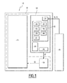
figure 1 is a schematic view of an installation including a displaying system according to a first embodiment of the invention; -
figure 2 is an enlarged view of a screen of the displaying system offigure 1 ; -
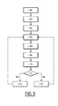
figure 3 is a flowchart of an example of method according to the first embodiment; -
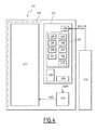
figure 4 is a schematic view of an installation including a displaying system according to a second embodiment of the invention; -
figure 5 is an enlarged view of a screen of the displaying system offigure 3 ; and -
figure 6 is a flowchart of an example of method according to the second embodiment. -
Figure 1 represents amain unit 10 connected to a displayingsystem 12. Themain unit 10 is configured to transmit a video signal S1 to the displayingsystem 12. Themain unit 10 receives, for example, some data relative to the functioning of a non-represented railway installation and is adapted to generate the video signal S1 in function of the received data. The received data correspond, for instance, to the state or position of a railroad switch. Themain unit 10 forms a safety system guarantying the integrity of the video signal S1. The main unit forms preferably a SIL4-type safety system (Safety Integrity Level 4) which guarantees a certain safety level and the integrity of the video signal S1 to avoid a wrong image visualization recognized as "good" by an operator. - The displaying
system 12 includes processing means 14 and amonitor 16. Themonitor 16 comprises ascreen 17 and control means 18 of thescreen 17. Themonitor 16 is, for instance, an ordinary LCD monitor currently used for word processing on a personal computer. - The video signal S1 comprises
information 19 to display on thescreen 17. The format of video signal S1 complies for example with Bitmap standard (BMP). Theinformation 19 is, for instance, related to the railway installation, i.e. relative to the functioning of trains, railway stations and/or railway lines. - The processing means 14 comprise a
processing unit 20, amemory 22, receivingmeans 24 of the video signal S1 and transmission means 26 of a command signal S2 to the control means 18. The processing means 14 are adapted to add additional data toinformation 19 comprised in the video signal S1 in order to generate the command signal S2. The processing means 14 form, for example, a central unit, such as the central unit of a computer, connected, on one hand, to themonitor 16, and on the other hand, to themain unit 10. - The format of the command signal S2 complies for example with Digital visual interface-digital standard (DVI-D).
- The
screen 17 includes non-represented pixels controlled by the control means 18. - The control means 18 are adapted to control the lighting and the colour of the pixels and therefore images displayed on the
screen 17, in function of the command signal S2. More especially, the control means 18 are adapted to control the lighting and the colour of the pixels via a control signal S3 of the pixels, which is function of the command signal S2 and which depends on the specifications of thescreen 17. In fact, the control means 18 control the colour and the lighting of the pixels in order to displayinformation 19 and the additional data on thescreen 17. - The
processing unit 20 is, for instance, a microcontroller and is adapted to execute algorithms comprised in thememory 22. - The
memory 22 comprises adetermination algorithm 28 of a topvertical position 30 and a bottomvertical position 32 on thescreen 17 as shown onfigure 2 and of associatedvisual reference indicators 34. Thememory 22 includes afirst displaying algorithm 36 of thevisual reference indicators 34 which indicate thetop 30 and/orbottom 32 vertical positions. Thememory 22 includes adefinition algorithm 38 of afirst display window 40, asecond displaying algorithm 41 of thefirst display window 40, acalculation algorithm 42 of a vertical position of thefirst display window 40 on thescreen 17 and acomparison algorithm 44 of the said vertical position with the top 30 andbottom 32 vertical positions. Thememory 22 includes also acommand algorithm 46 of the control means 18. - The transmission means 26 are adapted to periodically transmit the command signal S2 to the control means 18, in order to periodically actualize the images displayed on the
screen 17. - The
determination algorithm 28 is adapted to determine, for example in function of the dimensions of thescreen 17, the topvertical position 30 and the bottomvertical position 32, which define two reference positions of thefirst display window 40 on thescreen 17. More especially, the top 30 andbottom 32 vertical positions define two vertical positions between which a first givenpoint 55 of thefirst display window 40 is adapted to be displayed. In other words, thedetermination algorithm 28 is configured to determine two boundaries delimiting a vertical position of the first givenpoint 55 and therefore to determine a top position and a bottom position for thefirst display window 40. The dimensions of thescreen 17 are, for instance, transmitted by themonitor 16 when it is connected to the processing means 14. Thedetermination algorithm 28 is also adapted to determine thevisual reference indicators 34 in function of the top 30 and/or the bottom 32 vertical positions. - According to a variant of the invention, the top 30 and bottom 32 vertical positions define respectively the highest position at which a first given point of the
first display window 40 is adapted to be displayed and the lowest position at which a second given point of thefirst display window 40 is adapted to be displayed. - The
visual reference indicators 34 comprise several firsthorizontal lines 56 vertically adjacent to each other and extending between the top 30 and bottom 32 vertical positions, with an alternation of first horizontal lines of a first color and first horizontal lines of a second color. The highest firsthorizontal line 56 defines the topvertical position 30 and the lowest firsthorizontal line 56 defines the bottomvertical position 32. The first color is, for instance, the white color and the second color is, for instance, the black color. The firsthorizontal lines 56 have, for instance, a height of 1 pixel. The firsthorizontal lines 56 extend on all the length of thescreen 17. - The top 30 and bottom 32 vertical positions and more generally the
visual reference indicators 34 are adapted to have a fixed position on thescreen 17. - The first displaying
algorithm 36 is configured to command the displaying on thescreen 17 of thevisual reference indicators 34, which indicate the top 30 and/or bottom 32 vertical positions. The displayingalgorithm 36 is adapted to add to theinformation 19 comprised in video signal S1 some data corresponding to thevisual reference indicators 34 in order to generate the command signal S2 and to display thevisual reference indicators 34 on thescreen 17. - The
definition algorithm 38 is configured to define, for instance, the dimensions of thefirst display window 40 which is intended to comprise theinformation 19 to display and which is intended to be displayed on thescreen 17. The dimensions of thefirst display window 40 are lower than the dimension of thescreen 17. Thedefinition algorithm 38 is at least adapted to define the height of thefirst display window 40, which is lower than the height of thescreen 17. Thedefinition algorithm 38 is, for example, configured to define the dimensions of thefirst display window 40 in function of the dimensions of thescreen 17. The definition algorithm define, for instance, that the dimensions of thefirst display window 40 are 20% lower than the dimensions of thescreen 17. - According to a variant, the dimensions of the
first display window 40 are initially entered by the operator and saved in thememory 22. - The
definition algorithm 38 is also configured to define an initial vertical position of thefirst display window 40 on thescreen 17. The initial position corresponds, for example, to a previously saved in thememory 22 position for a central point of thefirst display window 40 on thescreen 17. - The second displaying
algorithm 41 is configured to integrate theinformation 19 comprised in the video signal S1, into thefirst display window 40, in order to generate the command signal S2. More especially, the command signal S2 contains data relative to thefirst display window 40 and to the referencevisual indicators 34 in order to display thefirst display window 40 on thescreen 17, over the referencevisual indicators 34, i.e. over the firsthorizontal lines 56. The second displayingalgorithm 41 is adapted to actualizeinformation 19 comprised in thefirst display window 40 periodically in function of the video signal S1. - The
calculation algorithm 42 of the vertical position of thefirst display window 40 is configured to calculate the vertical position of thefirst display window 40 on thescreen 17. Thecalculation algorithm 42 is for example adapted to save a first variable equal to the position of the first givenpoint 55 when thefirst display window 40 is in the initial position and to modify this variable each time the processing means 14 change the position of thefirst display window 40, in order to take this change into account. - The
comparison algorithm 44 is adapted to compare the vertical position of thefirst display window 40 with the top 30 and bottom 32 vertical positions. In other words, thecomparison algorithm 44 is adapted to check the position of thefirst display window 40, i.e. of the first givenpoint 55, relative to the top 30 and bottom 32 vertical positions. - The
command algorithm 46 is configured to command a vertical shift of thefirst display window 40, displayed on thescreen 17, over the firsthorizontal lines 56. The vertical shift corresponds to a shift of a predetermined number of pixels, preferably comprised between 1 and 6. More generally, the range of the vertical shift is for instance fixed by the operator and depends on a speed of movement chosen by the operator for thefirst display window 40. More especially, thecommand algorithm 46 is adapted to modify the position of thefirst display window 40, i.e. to modify the command signal S2, in order to change the position of thefirst display window 40 on thescreen 17, over the firsthorizontal lines 56. Therefore, thecalculation algorithm 42 is adapted to modify the first variable each time thecommand algorithm 46 command a vertical shift of thefirst display window 40. - The
command algorithm 46 is adapted to shift thefirst display window 40 relative to the referencevisual indicators 34 and, more especially, over the referencevisual indicators 34 in a predetermined direction. Preferably, the command algorithm is adapted to shift thefirst display window 40 over the firsthorizontal lines 56 of a predetermined number of firsthorizontal lines 56, preferably odd. - The
command algorithm 46 is adapted to be executed periodically by theprocessing unit 20 in order to command periodically, with a predetermined duration, the shift of thefirst display window 40 on thescreen 17, over the firsthorizontal lines 56. The predetermined duration is, for instance, preferably comprised between 1 s and 10 s. More generally, the predetermined duration is for instance fixed by the operator and depends on the speed of movement chosen by the operator for thefirst display window 40. - The
command algorithm 46 is adapted to determine the direction of the shift of thefirst display window 40 in function of the top 30 and bottom 32 vertical positions and of the vertical position of thefirst display window 40. More especially, thecommand algorithm 46 is configured to shift thefirst display window 40 in a new direction opposed to the topvertical position 30, respectively to the bottomvertical position 32, when thecomparison algorithm 44 detects that thefirst display window 40, i.e. the first givenpoint 55, has reached and/or exceeded the topvertical position 30 according to the predetermined direction, respectively the bottomvertical position 32 according to the predetermined direction. The command algorithm is then configured to fix the predetermined direction equal to the new direction. - According to a variant, the
calculation algorithm 42 is adapted to determine the vertical position of the first givenpoint 55 and of a second given point of thefirst display window 40. Thecomparison algorithm 44 is adapted to compare the vertical position of the first given point with the bottomvertical position 32 and the vertical position of the second given point with the topvertical position 30. Then thecommand algorithm 46 is configured to shift thefirst display window 40 in a first new direction opposed to the bottomvertical position 32, when thecomparison algorithm 44 detects that the first givenpoint 55, has reached and/or exceeded the bottomvertical position 32 according to the predetermined direction and in a second new direction opposed to the topvertical position 30, when thecomparison algorithm 44 detects that the second given point, has reached and/or exceeded the topvertical position 30 according to the predetermined direction. - An operating mode of the displaying
system 12 will be explained hereafter, through the presentation of the method illustrated inFigure 3 . - In an
initial reception step 100, the displayingsystem 12 receives the video signal S1. - Then, in a
determination step 102 the topvertical position 30 and the bottomvertical position 32 are determined by thedetermination algorithm 28. More especially, thevisual reference indicators 34 are determined. - Then, in a
definition step 104, thefirst display window 40 is defined by thedefinition algorithm 38 and comprises theinformation 19 to display. - In a
further calculation step 105, the vertical position of thefirst display window 40 on thescreen 17 is calculated through thecalculation algorithm 42. More especially, during thecalculation step 105, the value of the first variable is initially fixed equal to the position of the first givenpoint 55, when thefirst display window 40 is intended to be displayed at the initial position, i.e. just after thedefinition step 104, then the value of the first variable is modified after each shift of thefirst display window 40 realized by thecommand algorithm 46. In ageneration step 106, the command signal S2 is generated. More especially, theinformation 19 comprised in the video signal S1 is integrated, into thefirst display window 40 and some data corresponding to thevisual reference indicators 34 are added to thefirst display window 40 in order to generate the command signal S2. - In a
further transmission step 108, the command signal S2, which comprises data corresponding to thefirst display window 40 and to its calculated vertical position and to thevisual reference indicators 34, is transmitted, through the transmission means 26, to the control means 18. After thetransmission step 108, the control means 18 are able to control the pixels to display thefirst display window 40 and thevisual reference indicators 34 on thescreen 17, with thefirst display window 40 displayed over the firsthorizontal lines 56. - Then, in a displaying
step 110 the control signal S3 is transmitted to the pixels and thefirst display window 40 and thevisual reference indicators 34 are displayed on thescreen 17. - Then, during a
comparison step 114 the calculated vertical position is compared with the top 30 and bottom 32 vertical positions. - If during the
comparison step 114 the vertical position of the first givenpoint 55 is lower than the topvertical position 30 and higher than the bottomvertical position 32, then, in afirst command step 116, thecommand algorithm 46 commands a vertical shift of thefirst display window 40 on thescreen 17, relative to the top 30 and bottom 32 vertical positions in the predetermined direction. - If during the
comparison step 114 it has been detected that thefirst display window 40, i.e. the first givenpoint 55, has reached and/or exceeded the topvertical position 30, or the bottomvertical position 32 according to the predetermined direction, then, in asecond command step 118, the shift of thefirst display window 40 in a new direction opposed to the topvertical position 30, respectively to the bottomvertical position 32 is commanded. The first predetermined direction is fixed equal to this new direction. In other words, when the first givenpoint 55 vertical position is equal or higher than the topvertical position 30 or when the first givenposition 55 vertical position is equal or lower than the bottomvertical position 30 thesecond command step 118 is realized. - Following to the first 116 and/or second 118 command steps, the
calculation step 105 is repeated, which means that the first variable is modified according to the shift of thefirst display window 40. Thecalculation step 105 is, for instance, repeated with the predetermined duration. Thus, during thegeneration step 106, the video signal S1 considered corresponds to the last video signal S1 received by the processing means 14 and the position fixed for thefirst display window 40 in the command signal S2 corresponds to the calculated position. - Therefore, the
first display window 40 is regularly shifted and the operator is able to observe any dysfunction in the display, which means any pixel fault or dysfunction of the processing means 14 or control means 18. Indeed if a dysfunction occurs the operator would observe that a part of theinformation 19 displayed on thescreen 17 in thefirst window 40 is fixed and is not shifted compared with the rest of theinformation 19. The operator is able to observe the validity of the images displayed on the screen, checking the movement of thefirst display window 40 relative to thevisual reference indicators 34 which are fixed. More especially, thefirst display window 40 is, for instance, shifted over the firsthorizontal lines 56, and the number of firsthorizontal lines 56 displayed on thescreen 17 is function of the vertical position of thefirst display window 40. Therefore the operator is able to observe the shift or movement of thefirst display window 40 checking the number of firsthorizontal lines 56 displayed on thescreen 17 between thefirst display window 40 and the bottomvertical position 32. - In the following, a second embodiment of the invention, as presented on
figures 4 ,5 and6 will be described.Figure 4 represents amain unit 210 connected to a displayingsystem 212. In the second embodiment the element forming themain unit 210 and the displayingsystem 212 are globally similar than the ones presented in the first embodiment and have the same references increased of 200. In the following, only the difference between the first embodiment and the second embodiment will be presented. In fact, in the second embodiment, the displayingsystem 212 comprises the same elements than the displayingsystem 12 of the first embodiment plus some additional elements which are described below. - On
figure 4 , thememory 222 comprises acomputing algorithm 248 of asecond display window 250 and a computation algorithm 252 of athird display window 254. - The
computing algorithm 248 is configured to compute thesecond display window 250 which is associated with thefirst display window 240 and which is intended to be displayed on thescreen 217. Thecomputing algorithm 248 is also configured to define a first initial vertical top position and a first initial vertical bottom position of thesecond display window 250 on thescreen 217. The first initial top and bottom positions correspond for example to positions previously saved in thememory 222 by the operator. - The
second display window 250 comprises secondhorizontal lines 258, vertically adjacent to each other and intended to be displayed over the firsthorizontal lines 256, with an alternation of second horizontal lines of a third color and second horizontal lines of a fourth color. The second horizontal lines of the third color are, for instance, transparent and the fourth color is, for instance, the red color. The secondhorizontal lines 258 have, for instance, a height of 1 pixel. The secondhorizontal lines 258 extend over the firsthorizontal lines 256, on a length lower than thescreen 217 length. Thesecond display window 250 is configured to be disposed at a predetermined vertical distance of thefirst display window 240 and has a predetermined height. Thesecond display window 250 extends initially between the first initial top and bottom positions. - According to a variant, the second
horizontal lines 258 extend over the firsthorizontal lines 256, on a length equal to thescreen 217 length. - The
computing algorithm 248 is adapted to add into the command signal S202 some data corresponding to thesecond display window 250. More especially, the command signal S202 contains data relative to thesecond display window 250 in order to display thesecond display window 250 on thescreen 217, over the firsthorizontal lines 256. - In the second embodiment, the top vertical position 330 and the bottom vertical position 332 define two reference positions, i.e. two limit positions of the
second display window 250 on thescreen 17 - In this second embodiment, the
calculation algorithm 242 is adapted to calculate the vertical position of thesecond display window 250. Thecalculation algorithm 242 is, for example, adapted to save a second and a third variables equal respectively to the first initial vertical top and bottom positions. Thecalculation algorithm 242 is adapted to modify the second and third variables each time the processing means 14 change the position of the second display window 50, in order to take into account this change. The second and third variables correspond respectively to the vertical position of a third given point and of a fourth given point of thesecond display window 250. The third given point is, for instance, the highest point of thesecond display window 250 and the fourth given point is, for instance, the lowest point of thesecond display window 250. - The
comparison algorithm 244 is, for instance, adapted to compare the second variable with the topvertical position 230 and the third variable with the bottomvertical position 232. In other words, thecomparison algorithm 244 is adapted to check the position of thesecond display window 250 relative to the top 230 and bottom 232 vertical positions. - The
command algorithm 246 is configured to command a vertical shift in a predetermined direction of thesecond display window 250 and of thefirst display window 240 in a similar manner. The vertical distance between thefirst display window 240 and thesecond display window 250 stays fix. - The
command algorithm 246 is configured to command the vertical shift of thesecond display window 250 over the firsthorizontal lines 256 in order to have before the shift, the second horizontal lines of the third color respectively of the fourth color superimposed over the first horizontal lines of the first color respectively of the second color and, after the shift, the second horizontal lines of the fourth color respectively of the third color superimposed over the first horizontal lines of the first color respectively of the second color, or conversely. This creates flashing of thesecond display window 250 after each shift of thesecond display window 250. Indeed thesecond display window 250 is displayed over the firsthorizontal lines 256, then when the fourth color which is red is over the first color and the third color which is transparent is over the fourth color which is black, the operator observe a dark red color on thescreen 217 at the location of thesecond display window 250, which corresponds to an alternating of black and red horizontal lines. Moreover, when the fourth color is over the second color, the operator observe a pink color on thescreen 217 at the location of thesecond display window 250, which corresponds to an alternating of white and red horizontal lines. - In the second embodiment, the
command algorithm 246 is adapted to determine the direction of the shift of the first 240 and second 250 display windows in function of the second and third variables and of the top 230 and bottom 232 vertical positions. More especially, thecommand algorithm 246 is configured to shift the first 240 and second 250 display windows in a new direction opposed to the topvertical position 230, respectively to the bottomvertical position 232, when thecomparison algorithm 244 detects that thesecond display window 250, has reached and/or exceeded the topvertical position 230 according to the predetermined direction, respectively the bottomvertical position 232 according to the predetermined direction. Thecommand algorithm 246 is configured to vertically shift the first 240 and second 250 display windows relative to thevisual reference indicators 234. More especially, thesecond display window 250 is vertically shifted over the referencevisual indicators 234, i.e. over the firsthorizontal lines 256 and stays comprise between the top 230 and bottom 232 vertical positions. - More especially, the
command algorithm 246 is adapted to modify the position of the first 240 and second 250 display windows, i.e. to modify the command signal S202, in order to change the position of the first 240 and second 250 display windows on thescreen 17. Therefore, thecalculation algorithm 242 is adapted to modify the second and third variable each time thecommand algorithm 246 command a vertical shift of thesecond display window 250. - The
command algorithm 246 is adapted to be executed periodically by theprocessing unit 20 in order to command periodically, with a predetermined duration, the shift of the first 240 and second 250 display windows on thescreen 217. The predetermined duration is, for instance, preferably comprised between 1 s and 10 s. More generally, the predetermined duration is for instance fixed by the operator and depends on a speed of movement chosen by the operator for the first 240 and second 250 display windows. - The computation algorithm 252 is configured to compute the
third display window 254 which is intended to be displayed over the firsthorizontal lines 256. - The third display window 252 is preferably displayed at the same height than the
second display window 250 and extends initially between the first initial top and bottom positions. Thethird display window 254 is preferably horizontally adjacent to thesecond display window 250. - The
third display window 254 includes safetyvisual indicators 259 and the computation algorithm 252 is adapted to actualize regularly the safetyvisual indicators 259 and therefore to modify thethird display window 254 and so, the command signal S202. - The safety
visual indicators 259 allow the operator to check the validity of the images and therefore of theinformation 219 displayed on thescreen 217. The safetyvisual indicators 259 include arotating bar 260 which is intended to rotate with a first predetermined period, which is, for instance, comprised between 0.2 seconds (s) and 3 s. - The safety
visual indicators 259 include also areference time 264 which is, for instance, refreshed by the computation algorithm 252 every second and the operator can check the validity of theinformation 219 displayed, checking that thereference time 264 is changing. - The safety
visual indicators 259 include afix color bar 266 comprising several color blocks adjacent to each other and which is associated with adynamic color bar 268 similar to thefix color bar 266. Thefix color bar 266 comprises, for instance, five color blocks adjacent to each other and extends horizontally. Thedynamic color bar 268 is displayed below thefix color bar 266. - The
dynamic color bar 268 is comprised in thethird display window 254, and therefore, in the command signal S202, for instance, every second predetermined period. More especially thedynamic color bar 268 is alternately not displayed in thethird display window 254 during a duration equal to the second predetermined period and displayed in thethird display window 254. Therefore, thedynamic color bar 268 is displayed periodically with the second predetermined period. The second predetermined period is, for instance, equal to 1 s. - According to a variant, the
third display window 254 includes a non-represented dynamic color bar comprising, for instance, several color blocks whose positions are exchanged periodically with a third predetermined period. The third predetermined period is, for instance, equal to 1 s. - According to another variant, the third display window includes the
fix color bar 266, but not thedynamic color bar 268. - Advantageously, the
third display window 254 defines an area, for instance a horizontal bar, comprising the safetyvisual indicators 259. - The
computing algorithm 248 is adapted to add into the command signal S2 some data corresponding to thethird display window 254. More especially, the command signal S2 contains data relative to thethird display window 254 in order to display thethird display window 254 on thescreen 217, over the firsthorizontal lines 256. - Advantageously, the
command algorithm 246 is configured to command a vertical shift of thethird display window 254 in a similar manner than the shift of the first 240 and second 250 display windows. More especially, knowing that thethird display window 254 is horizontally adjacent to thesecond display window 250, the vertical positions of the second 250 and third 254 display windows are globally equivalent. - According to a variant, the computation algorithm 252 is also configured to define a second initial vertical top and a second initial vertical bottom position of the
third display window 254 on thescreen 217. The second initial top and bottom positions correspond for example to vertical positions previously saved in thememory 22. Then, thecalculation algorithm 242 is adapted to calculate the vertical position of thethird display window 254. Thecalculation algorithm 242 is for example adapted to save a fifth and a sixth variables equal respectively to the second initial vertical top and bottom positions of thethird display window 254. Thecalculation algorithm 242 is adapted to modify the fifth and sixth variables each time the processing means 14 change the position of thethird display window 254, in order to take in account this change. Then, thecomparison algorithm 244 is, for instance, adapted to check the position of thethird display window 254 relative to the top 230 and bottom 232 vertical positions and thecommand algorithm 246 is adapted to determine the direction of the shift of the first 240, second 250 and third 254 display windows in function of the fifth and sixth variables and of the top 230 and bottom 232 vertical positions. - An operating mode of the displaying
system 212 will be explained hereafter, through the presentation of the method illustrated inFigure 6 . - This method comprises an
initial reception step 300, adetermination step 302, adefinition step 304 and ageneration step 306 respectively similar to thereception step 100,determination step 102,definition step 104 andgeneration step 106 presented for the first embodiment. - Then in a
further computing step 308, thesecond display window 250 is computed by thecomputing algorithm 248 and in acomputation step 310, thethird display window 254 is defined by the computation algorithm 252. More especially, some data corresponding to the second 250 and third 254 display windows are added to the command signal S202. - In a
further calculation step 311, the vertical position of thesecond display window 250 on thescreen 217 is calculated through thecalculation algorithm 242. More especially the second and third variables are initially fixed equal to the first initial vertical top and bottom position, the first time that thecalculation step 311 is realized, then the values of the second and third variables are modified after each shift of thesecond display window 250 commanded by thecommand algorithm 246. In afurther transmission step 312, the command signal S202, which comprises data corresponding to the first 240, second 250 and third 254 display windows and to thevisual reference indicators 234 is transmitted, through the transmission means 226, to the control means 218. After thetransmission step 312, the control means 218 are able to display the first 240, second 250 and third 254 display windows and thevisual reference indicators 234 on thescreen 217, with notably the second and third display windows displayed over the firsthorizontal lines 256. - Then, in a displaying
step 314 the control signal S3 is transmitted to pixels and the first 240, second 250 and third 254 display windows and thevisual reference indicators 234 are displayed on thescreen 217. - Then, during a
comparison step 318 the second and third variables are respectively compared with the top 230 and bottom 232 vertical positions. - Finally, if during the
comparison step 318 the second variable, i.e. the vertical position of the third given point is lower than the topvertical position 230 or the third variable, i.e. the vertical position of the fourth given point, is higher than the bottomvertical position 232, then, in afirst command step 320, thecommand algorithm 246 commands a vertical shift of the first 240, second 250 and third 254 display windows on thescreen 217, relative to the top 230 and bottom 232 vertical positions in the predetermined direction. The condition presented above corresponds to the fact that thesecond display window 250 has not reached and/or exceeded the topvertical position 230 or the bottomvertical position 232, according to the predetermined direction. - Then, if during the
comparison step 318 it has been detected that the second variable, i.e. the vertical position of the third given point, is higher than or equal to the topvertical position 230 or that the third variable, i.e. the vertical position of the fourth given point, is lower than or equal to the bottomvertical position 232, then, in asecond command step 322, thecommand algorithm 246 commands the shift of the first 240, second 250 and third 254 display windows in a new direction opposed to the topvertical position 230, respectively to the bottomvertical position 232 and the first predetermined direction is fixed equal to this new direction. The condition presented above corresponds to the fact that thesecond display window 250 has reached and/or exceeded the topvertical position 230 or the bottomvertical position 232, according to the predetermined direction. - Following to the first 320 and/or second 322 command steps, the
generation step 306 is repeated, which means that thecalculation step 311 is also repeated and that the second and third variables are modified according to the shift command in thecommand step generation 306,computing 308 andcomputation 310 steps are executed and the command signal S202 is modified according to the shift command in order to vertically shift the first 240, second 250 and third 254 display windows. In other words, after thecommand step generation 306,computing 308 andcomputation 310 steps. - The operator is able to observe the validity of the images displayed on the screen, checking the movement of the first 240, second 250 and third 254 display windows relative to the
visual reference indicators 234 which are fixed. - In addition, the
generation 306, computing 308,computation 310,calculation 311,transmission 312, displaying 314,comparison 318 andcommand information 219 displayed on thescreen 217. This notably enables to shift periodically the first 240, second 250 and third 254 windows and to actualize the data displayed in thethird display window 254, i.e. the safetyvisual indicators 259. Therefore the operator is able to observe the safetyvisual indicators 259 to check the validity of the images and therefore of theinformation 219 displayed on thescreen 217. Indeed the operator check the rotation of therotating bar 260, the changing of thereference time 264, the displaying of the firstfix color bar 266 and the flashing of the firstdynamic color bar 268 and identify a dysfunction in the displaying system, for instance, if no rotation is observed or if the reference time does not change or if thefix color bar 266 is not correctly displayed. The repetition of the first 320 and/or second 322 command steps allows the operator to check that the first 240, second 250 and third 254 display windows are periodically shifted. - The operator is able to check the validity of the
information 219, by checking the flashing related to the shift of thesecond display window 250 relative to thevisual reference indicators 234, i.e. to the movement of the secondhorizontal lines 258 over the firsthorizontal lines 256. - The operator is also able to observe any dysfunction in the display, which means any pixel fault or dysfunction of the processing means 214 or control means 218, because if a dysfunction occurs the operator would observe that a part of the
information 219 or of the visual indicators 229 displayed on thescreen 217 is fixed and is not shifted compared with the rest of theinformation 219 or of the visual reference indicators 229. The operator is able to observe the validity of the images displayed on the screen, checking the movement of the first 240, second 250 and third 254 display windows relative to thevisual reference indicators 234 which are fixed. - For example, the operator is able to check if a pixel fault occurs because, if a pixel fault occurs, the operator would observe that the first 240, second 250 and third 254 windows are shifted on the
screen 217, whereas the faulty pixel would not move. - According to a variant of the invention, the processing means 14 are integrated in the
main unit 10. In this variant the displayingsystem 12 comprises themain unit 10. - According to another variant, the first, second and third display windows are associated together in a main window which is shifted through the use of the
command algorithm 246 and actualized through the use of the second displayingalgorithm 241,computing algorithm 248 andcomputation algorithm 250. In this variant thedefinition step 238 can be replace by a definition step of the main window. In this variant the main window corresponds, for example to thefirst display window 240 in which the second 250 and third 254 display windows are integrated. - According to another variant the shift of the first 40, 240, second 250 and third 254 display windows is not a vertical shift but a horizontal shift. Therefore in the preceding description the words "vertical", "top" and bottom" would be replaced, where appropriate, by the words "horizontal", "left" and "right".
- According to another variant the shift of the first 40, 240, second 250 and third 254 display windows is both vertical and horizontal.
- The embodiments and variants discussed above are suitable for being combined with one another wholly or partially to give rise to other embodiments of the invention.
Claims (10)
- Method for displaying information (19; 219) on a screen (17; 217) of a displaying system (12; 212), the screen (17; 217) including pixels and the displaying system (12; 212) comprising processing means (14; 214) and control means (18; 218) of the pixels, the method comprising the following step:- the reception (100; 300), by the processing means (14; 214), of a video signal (S1; S201) comprising the information (19; 219),characterized in that following to the reception step (100; 300) the method comprises the following steps:- the determination (102; 302) of visual reference indicators (34; 234) intended to be displayed on the screen (17; 217),- the definition (104; 304) of a first display window (40; 240) comprising the information (19; 219) to display, the first display window (40; 240) being intended to be displayed on the screen (17; 217) and the dimensions of the first display window (40; 240) being lower than the dimensions of the screen (17; 217),- the displaying (110; 314) of the first display window (40; 240) and of the visual reference indicators (34; 234) on the screen (17; 217),- the command (116, 118; 320, 322) of a shift in a predetermined direction of the first display window (40; 240), displayed on the screen (17; 217), relative to the visual reference indicators (34; 234).
- Method according to claim 1, characterized in that, in the command step (116, 118), the first display window (40) is shifted over the visual reference indicators (34).
- Method according to any of the preceding claims, characterized in that during the determination step (102) a first (30) limit position and a second (32) limit position on the screen (17) are determined, the first limit position (30) defining a limit position of a first given point (55) of the first display window (40) and the second limit position (32) defining a limit position of a second given point (55) of the first display window (40), and in that the visual reference indicators (34) indicate at least the first and second limit positions on the screen (17).
- Method according to claim 3, characterized in that the method comprises, previously to the displaying step (110), the following steps:- the calculation (105) of a position of the first display window (40) on the screen (17),- the comparison (114) between the calculated position and the first (30) and second (32) limit positions,and in that if during the comparison step (116) it has been detected that the first given point has reached and/or exceeded the first limit position (30) according to the predetermined direction, or that the second given point has reached and/or exceeded the second limit position (32) according to the predetermined direction, then, during the command step (118), first display window (40) is shifted in a new direction opposed to the first limit position (30), respectively to the second limit position (32) and the predetermined direction is fixed equal to this new direction.
- Method according to any of the preceding claims, characterized in that the visual reference indicators (34; 234) are fixed on the screen (17; 217) and comprise several first lines (56; 256) adjacent to each other according to the predetermined direction, with an alternation of first lines of a first color and first lines of a second color, and in that during the command step the first display window (40; 240) is adapted to be shifted over the first lines (56; 256) of a predetermined number of first lines (56; 256).
- Method according to claim 5, characterized in that previously to the displaying step (314) and following to the definition step (304), the method comprises the following step:- the computing (308) of a second display window (250) comprising second lines (258), adjacent to each other according to the predetermined direction and intended to be displayed over the first lines (256), with an alternation of second lines (258) of a third color and second lines (258) of a fourth color,in that, during the displaying step (314), the second display window (250) is displayed on the screen (217), and in that, during the command step, (320, 322) the second display window (250) is shifted in the predetermined direction over the first lines (256) in order to have before the shift, the second lines (258) of the third color respectively of the fourth color superimposed over the first lines (256) of the first color respectively of the second color and, after the shift, the second lines (258) of the fourth color respectively of the third color superimposed over the first lines (256) of the first color respectively of the second color, or conversely.
- Method according to any of the preceding claims, characterized in that the video signal (S1; S201) is generated by a main unit (10; 210) which forms a safety system guarantying the integrity of the video signal (S1; S201), the main unit forming preferably a SIL4-type safety system.
- Method according to any of the preceding claims, characterized in that the command step (116, 118; 320, 322) is periodically repeated, with a predetermined duration, preferably comprised between 1 s and 10 s.
- Method according to any of the preceding claims, characterized in that previously to the displaying step (314) and following to the definition step (304), the method comprises the following step:- the computation (308) of a third display window (254) comprising safety visual indicators (259) belonging to the group formed by: a rotating bar (260) with a first predetermined period, a first fix color bar comprising several color blocks adjacent to each other, a reference time (264), a second fix color bar (266) comprising several color blocks adjacent to each other associated with a first dynamic color bar (268) similar to the second fix color bar (266), displayed below the second fix color bar (266) and displayed periodically with a second predetermined period, a second dynamic color bar comprising several color blocks whose positions are exchanged periodically with a third predetermined period,and in that, during the displaying step (314), the third display window (254) is displayed on the screen (217).
- Displaying system (12; 212), comprising processing means (14; 214), a screen (17; 217) including pixels and configured to display information (19; 219) and control means (18; 218) of the pixels, the processing means (14; 214) comprising receiving means (24; 224) of a video signal (S1; S201) comprising the information (19; 219), characterized in that the processing means (14; 214) comprise determination means of visual reference indicators (34; 234) intended to be displayed on the screen (17; 217), definition means (28; 228) configured to define a first display window (40; 240) including the information (19; 219) to display, the first display window (40; 240) being intended to be displayed on the screen (17; 217), the dimensions of the first display window (40; 240) being lower than the dimensions of the screen (17; 217) and displaying means (36, 41; 236, 241) configured to display the first display window (40; 240) and the visual reference indicators (34; 234) on the screen and in that the processing means (14; 214) comprise command means (46; 246) configured to command a shift in a predetermined direction of the first display window (40; 240), displayed on the screen (17; 217), relative to the visual reference indicators (34; 234).
Priority Applications (2)
| Application Number | Priority Date | Filing Date | Title |
|---|---|---|---|
| ES14306104T ES2810231T3 (en) | 2014-07-04 | 2014-07-04 | Method of displaying information on a screen of a display system and display system |
| EP14306104.2A EP2963640B1 (en) | 2014-07-04 | 2014-07-04 | Method for displaying information on a screen of a displaying system and displaying system |
Applications Claiming Priority (1)
| Application Number | Priority Date | Filing Date | Title |
|---|---|---|---|
| EP14306104.2A EP2963640B1 (en) | 2014-07-04 | 2014-07-04 | Method for displaying information on a screen of a displaying system and displaying system |
Publications (2)
| Publication Number | Publication Date |
|---|---|
| EP2963640A1 true EP2963640A1 (en) | 2016-01-06 |
| EP2963640B1 EP2963640B1 (en) | 2020-06-17 |
Family
ID=51211710
Family Applications (1)
| Application Number | Title | Priority Date | Filing Date |
|---|---|---|---|
| EP14306104.2A Active EP2963640B1 (en) | 2014-07-04 | 2014-07-04 | Method for displaying information on a screen of a displaying system and displaying system |
Country Status (2)
| Country | Link |
|---|---|
| EP (1) | EP2963640B1 (en) |
| ES (1) | ES2810231T3 (en) |
Cited By (1)
| Publication number | Priority date | Publication date | Assignee | Title |
|---|---|---|---|---|
| CN112597931A (en) * | 2020-12-28 | 2021-04-02 | 京东数字科技控股股份有限公司 | Screen state detection method and device, electronic equipment, server and storage medium |
Citations (2)
| Publication number | Priority date | Publication date | Assignee | Title |
|---|---|---|---|---|
| JP2001265312A (en) * | 2000-03-23 | 2001-09-28 | Ricoh Co Ltd | Defective pixel management device and window management device for display device |
| EP1511001A1 (en) * | 2003-08-25 | 2005-03-02 | Agfa-Gevaert | Method and user interface for detecting whether a pixel in a displayed image constitutes a dead pixel of a display device. |
-
2014
- 2014-07-04 ES ES14306104T patent/ES2810231T3/en active Active
- 2014-07-04 EP EP14306104.2A patent/EP2963640B1/en active Active
Patent Citations (2)
| Publication number | Priority date | Publication date | Assignee | Title |
|---|---|---|---|---|
| JP2001265312A (en) * | 2000-03-23 | 2001-09-28 | Ricoh Co Ltd | Defective pixel management device and window management device for display device |
| EP1511001A1 (en) * | 2003-08-25 | 2005-03-02 | Agfa-Gevaert | Method and user interface for detecting whether a pixel in a displayed image constitutes a dead pixel of a display device. |
Cited By (1)
| Publication number | Priority date | Publication date | Assignee | Title |
|---|---|---|---|---|
| CN112597931A (en) * | 2020-12-28 | 2021-04-02 | 京东数字科技控股股份有限公司 | Screen state detection method and device, electronic equipment, server and storage medium |
Also Published As
| Publication number | Publication date |
|---|---|
| EP2963640B1 (en) | 2020-06-17 |
| ES2810231T3 (en) | 2021-03-08 |
Similar Documents
| Publication | Publication Date | Title |
|---|---|---|
| DE102008016527B4 (en) | Vehicle measuring device unit and display device | |
| KR102532971B1 (en) | Display Device and Driving Method thereof | |
| US20160363993A1 (en) | Transparent display system and apparatus provided with the same | |
| DE112015003650T5 (en) | DISPLAY DEVICE | |
| JP2008283431A (en) | Image processing device | |
| CN105376525A (en) | Vehicle camera system having live video indication | |
| EP2963640B1 (en) | Method for displaying information on a screen of a displaying system and displaying system | |
| US9508111B1 (en) | Method and system for detecting a display mode suitable for a reduced refresh rate | |
| JP2015535948A5 (en) | ||
| US9770948B2 (en) | Display device | |
| JP6597028B2 (en) | Display device | |
| US20150177561A1 (en) | Display apparatus and display method | |
| US20150116292A1 (en) | Display device and method for driving the same | |
| KR102625935B1 (en) | Apparatus and method for validating image data in a display device | |
| BRPI1105104A2 (en) | process for verifying pixel-formatted display data for presentation on a display of a pointing device on a vehicle | |
| EP3405944B1 (en) | Apparatus and method for checking a validity of image data in a display device by including checking data | |
| US20180108326A1 (en) | Display device | |
| JP2016099361A (en) | Display device, display method and image output device | |
| JP6139971B2 (en) | Vehicle equipment | |
| CN115509477B (en) | Method, device, equipment and medium for dynamically displaying character images in vehicle-mounted display screen | |
| US20060132509A1 (en) | Apparatus and method for reducing color error in display having sub-pixel structure | |
| JP2004139297A (en) | Alarm display | |
| EP3788635A1 (en) | Method for operating electronic data glasses in a motor vehicle, and electronic data glasses | |
| CN107548367B (en) | Method and device for displaying the course of at least one railway safety device and railway safety system having such a device | |
| JP7336979B2 (en) | Failure Sign Detection System for Television Monitor Equipment for Surveillance |
Legal Events
| Date | Code | Title | Description |
|---|---|---|---|
| PUAI | Public reference made under article 153(3) epc to a published international application that has entered the european phase |
Free format text: ORIGINAL CODE: 0009012 |
|
| AK | Designated contracting states |
Kind code of ref document: A1 Designated state(s): AL AT BE BG CH CY CZ DE DK EE ES FI FR GB GR HR HU IE IS IT LI LT LU LV MC MK MT NL NO PL PT RO RS SE SI SK SM TR |
|
| AX | Request for extension of the european patent |
Extension state: BA ME |
|
| 17P | Request for examination filed |
Effective date: 20160706 |
|
| RBV | Designated contracting states (corrected) |
Designated state(s): AL AT BE BG CH CY CZ DE DK EE ES FI FR GB GR HR HU IE IS IT LI LT LU LV MC MK MT NL NO PL PT RO RS SE SI SK SM TR |
|
| RAP1 | Party data changed (applicant data changed or rights of an application transferred) |
Owner name: ALSTOM TRANSPORT TECHNOLOGIES |
|
| STAA | Information on the status of an ep patent application or granted ep patent |
Free format text: STATUS: EXAMINATION IS IN PROGRESS |
|
| 17Q | First examination report despatched |
Effective date: 20170526 |
|
| GRAP | Despatch of communication of intention to grant a patent |
Free format text: ORIGINAL CODE: EPIDOSNIGR1 |
|
| STAA | Information on the status of an ep patent application or granted ep patent |
Free format text: STATUS: GRANT OF PATENT IS INTENDED |
|
| INTG | Intention to grant announced |
Effective date: 20200130 |
|
| GRAS | Grant fee paid |
Free format text: ORIGINAL CODE: EPIDOSNIGR3 |
|
| GRAA | (expected) grant |
Free format text: ORIGINAL CODE: 0009210 |
|
| STAA | Information on the status of an ep patent application or granted ep patent |
Free format text: STATUS: THE PATENT HAS BEEN GRANTED |
|
| AK | Designated contracting states |
Kind code of ref document: B1 Designated state(s): AL AT BE BG CH CY CZ DE DK EE ES FI FR GB GR HR HU IE IS IT LI LT LU LV MC MK MT NL NO PL PT RO RS SE SI SK SM TR |
|
| REG | Reference to a national code |
Ref country code: GB Ref legal event code: FG4D |
|
| REG | Reference to a national code |
Ref country code: CH Ref legal event code: EP |
|
| REG | Reference to a national code |
Ref country code: DE Ref legal event code: R096 Ref document number: 602014066649 Country of ref document: DE |
|
| REG | Reference to a national code |
Ref country code: IE Ref legal event code: FG4D |
|
| REG | Reference to a national code |
Ref country code: AT Ref legal event code: REF Ref document number: 1282300 Country of ref document: AT Kind code of ref document: T Effective date: 20200715 |
|
| PG25 | Lapsed in a contracting state [announced via postgrant information from national office to epo] |
Ref country code: FI Free format text: LAPSE BECAUSE OF FAILURE TO SUBMIT A TRANSLATION OF THE DESCRIPTION OR TO PAY THE FEE WITHIN THE PRESCRIBED TIME-LIMIT Effective date: 20200617 Ref country code: GR Free format text: LAPSE BECAUSE OF FAILURE TO SUBMIT A TRANSLATION OF THE DESCRIPTION OR TO PAY THE FEE WITHIN THE PRESCRIBED TIME-LIMIT Effective date: 20200918 Ref country code: NO Free format text: LAPSE BECAUSE OF FAILURE TO SUBMIT A TRANSLATION OF THE DESCRIPTION OR TO PAY THE FEE WITHIN THE PRESCRIBED TIME-LIMIT Effective date: 20200917 Ref country code: LT Free format text: LAPSE BECAUSE OF FAILURE TO SUBMIT A TRANSLATION OF THE DESCRIPTION OR TO PAY THE FEE WITHIN THE PRESCRIBED TIME-LIMIT Effective date: 20200617 Ref country code: SE Free format text: LAPSE BECAUSE OF FAILURE TO SUBMIT A TRANSLATION OF THE DESCRIPTION OR TO PAY THE FEE WITHIN THE PRESCRIBED TIME-LIMIT Effective date: 20200617 |
|
| REG | Reference to a national code |
Ref country code: LT Ref legal event code: MG4D |
|
| REG | Reference to a national code |
Ref country code: NL Ref legal event code: MP Effective date: 20200617 |
|
| PG25 | Lapsed in a contracting state [announced via postgrant information from national office to epo] |
Ref country code: HR Free format text: LAPSE BECAUSE OF FAILURE TO SUBMIT A TRANSLATION OF THE DESCRIPTION OR TO PAY THE FEE WITHIN THE PRESCRIBED TIME-LIMIT Effective date: 20200617 Ref country code: LV Free format text: LAPSE BECAUSE OF FAILURE TO SUBMIT A TRANSLATION OF THE DESCRIPTION OR TO PAY THE FEE WITHIN THE PRESCRIBED TIME-LIMIT Effective date: 20200617 Ref country code: RS Free format text: LAPSE BECAUSE OF FAILURE TO SUBMIT A TRANSLATION OF THE DESCRIPTION OR TO PAY THE FEE WITHIN THE PRESCRIBED TIME-LIMIT Effective date: 20200617 Ref country code: BG Free format text: LAPSE BECAUSE OF FAILURE TO SUBMIT A TRANSLATION OF THE DESCRIPTION OR TO PAY THE FEE WITHIN THE PRESCRIBED TIME-LIMIT Effective date: 20200917 |
|
| REG | Reference to a national code |
Ref country code: AT Ref legal event code: MK05 Ref document number: 1282300 Country of ref document: AT Kind code of ref document: T Effective date: 20200617 |
|
| PG25 | Lapsed in a contracting state [announced via postgrant information from national office to epo] |
Ref country code: AL Free format text: LAPSE BECAUSE OF FAILURE TO SUBMIT A TRANSLATION OF THE DESCRIPTION OR TO PAY THE FEE WITHIN THE PRESCRIBED TIME-LIMIT Effective date: 20200617 Ref country code: NL Free format text: LAPSE BECAUSE OF FAILURE TO SUBMIT A TRANSLATION OF THE DESCRIPTION OR TO PAY THE FEE WITHIN THE PRESCRIBED TIME-LIMIT Effective date: 20200617 |
|
| PG25 | Lapsed in a contracting state [announced via postgrant information from national office to epo] |
Ref country code: AT Free format text: LAPSE BECAUSE OF FAILURE TO SUBMIT A TRANSLATION OF THE DESCRIPTION OR TO PAY THE FEE WITHIN THE PRESCRIBED TIME-LIMIT Effective date: 20200617 Ref country code: PT Free format text: LAPSE BECAUSE OF FAILURE TO SUBMIT A TRANSLATION OF THE DESCRIPTION OR TO PAY THE FEE WITHIN THE PRESCRIBED TIME-LIMIT Effective date: 20201019 Ref country code: CZ Free format text: LAPSE BECAUSE OF FAILURE TO SUBMIT A TRANSLATION OF THE DESCRIPTION OR TO PAY THE FEE WITHIN THE PRESCRIBED TIME-LIMIT Effective date: 20200617 Ref country code: EE Free format text: LAPSE BECAUSE OF FAILURE TO SUBMIT A TRANSLATION OF THE DESCRIPTION OR TO PAY THE FEE WITHIN THE PRESCRIBED TIME-LIMIT Effective date: 20200617 Ref country code: SM Free format text: LAPSE BECAUSE OF FAILURE TO SUBMIT A TRANSLATION OF THE DESCRIPTION OR TO PAY THE FEE WITHIN THE PRESCRIBED TIME-LIMIT Effective date: 20200617 |
|
| PG25 | Lapsed in a contracting state [announced via postgrant information from national office to epo] |
Ref country code: SK Free format text: LAPSE BECAUSE OF FAILURE TO SUBMIT A TRANSLATION OF THE DESCRIPTION OR TO PAY THE FEE WITHIN THE PRESCRIBED TIME-LIMIT Effective date: 20200617 Ref country code: PL Free format text: LAPSE BECAUSE OF FAILURE TO SUBMIT A TRANSLATION OF THE DESCRIPTION OR TO PAY THE FEE WITHIN THE PRESCRIBED TIME-LIMIT Effective date: 20200617 Ref country code: IS Free format text: LAPSE BECAUSE OF FAILURE TO SUBMIT A TRANSLATION OF THE DESCRIPTION OR TO PAY THE FEE WITHIN THE PRESCRIBED TIME-LIMIT Effective date: 20201017 |
|
| REG | Reference to a national code |
Ref country code: CH Ref legal event code: PL |
|
| REG | Reference to a national code |
Ref country code: ES Ref legal event code: FG2A Ref document number: 2810231 Country of ref document: ES Kind code of ref document: T3 Effective date: 20210308 |
|
| REG | Reference to a national code |
Ref country code: DE Ref legal event code: R097 Ref document number: 602014066649 Country of ref document: DE |
|
| PG25 | Lapsed in a contracting state [announced via postgrant information from national office to epo] |
Ref country code: MC Free format text: LAPSE BECAUSE OF FAILURE TO SUBMIT A TRANSLATION OF THE DESCRIPTION OR TO PAY THE FEE WITHIN THE PRESCRIBED TIME-LIMIT Effective date: 20200617 |
|
| PLBE | No opposition filed within time limit |
Free format text: ORIGINAL CODE: 0009261 |
|
| STAA | Information on the status of an ep patent application or granted ep patent |
Free format text: STATUS: NO OPPOSITION FILED WITHIN TIME LIMIT |
|
| REG | Reference to a national code |
Ref country code: BE Ref legal event code: MM Effective date: 20200731 |
|
| PG25 | Lapsed in a contracting state [announced via postgrant information from national office to epo] |
Ref country code: DK Free format text: LAPSE BECAUSE OF FAILURE TO SUBMIT A TRANSLATION OF THE DESCRIPTION OR TO PAY THE FEE WITHIN THE PRESCRIBED TIME-LIMIT Effective date: 20200617 Ref country code: CH Free format text: LAPSE BECAUSE OF NON-PAYMENT OF DUE FEES Effective date: 20200731 Ref country code: LI Free format text: LAPSE BECAUSE OF NON-PAYMENT OF DUE FEES Effective date: 20200731 Ref country code: IE Free format text: LAPSE BECAUSE OF NON-PAYMENT OF DUE FEES Effective date: 20200704 Ref country code: LU Free format text: LAPSE BECAUSE OF NON-PAYMENT OF DUE FEES Effective date: 20200704 |
|
| 26N | No opposition filed |
Effective date: 20210318 |
|
| PG25 | Lapsed in a contracting state [announced via postgrant information from national office to epo] |
Ref country code: BE Free format text: LAPSE BECAUSE OF NON-PAYMENT OF DUE FEES Effective date: 20200731 Ref country code: SI Free format text: LAPSE BECAUSE OF FAILURE TO SUBMIT A TRANSLATION OF THE DESCRIPTION OR TO PAY THE FEE WITHIN THE PRESCRIBED TIME-LIMIT Effective date: 20200617 |
|
| PG25 | Lapsed in a contracting state [announced via postgrant information from national office to epo] |
Ref country code: TR Free format text: LAPSE BECAUSE OF FAILURE TO SUBMIT A TRANSLATION OF THE DESCRIPTION OR TO PAY THE FEE WITHIN THE PRESCRIBED TIME-LIMIT Effective date: 20200617 Ref country code: MT Free format text: LAPSE BECAUSE OF FAILURE TO SUBMIT A TRANSLATION OF THE DESCRIPTION OR TO PAY THE FEE WITHIN THE PRESCRIBED TIME-LIMIT Effective date: 20200617 Ref country code: CY Free format text: LAPSE BECAUSE OF FAILURE TO SUBMIT A TRANSLATION OF THE DESCRIPTION OR TO PAY THE FEE WITHIN THE PRESCRIBED TIME-LIMIT Effective date: 20200617 |
|
| PG25 | Lapsed in a contracting state [announced via postgrant information from national office to epo] |
Ref country code: MK Free format text: LAPSE BECAUSE OF FAILURE TO SUBMIT A TRANSLATION OF THE DESCRIPTION OR TO PAY THE FEE WITHIN THE PRESCRIBED TIME-LIMIT Effective date: 20200617 |
|
| P01 | Opt-out of the competence of the unified patent court (upc) registered |
Effective date: 20230823 |
|
| REG | Reference to a national code |
Ref country code: GB Ref legal event code: 732E Free format text: REGISTERED BETWEEN 20250213 AND 20250219 |
|
| REG | Reference to a national code |
Ref country code: ES Ref legal event code: PC2A Owner name: ALSTOM HOLDINGS Effective date: 20250310 |
|
| PGFP | Annual fee paid to national office [announced via postgrant information from national office to epo] |
Ref country code: RO Payment date: 20250630 Year of fee payment: 12 |
|
| PGFP | Annual fee paid to national office [announced via postgrant information from national office to epo] |
Ref country code: ES Payment date: 20250826 Year of fee payment: 12 |
|
| PGFP | Annual fee paid to national office [announced via postgrant information from national office to epo] |
Ref country code: DE Payment date: 20250722 Year of fee payment: 12 |
|
| PGFP | Annual fee paid to national office [announced via postgrant information from national office to epo] |
Ref country code: IT Payment date: 20250724 Year of fee payment: 12 |
|
| PGFP | Annual fee paid to national office [announced via postgrant information from national office to epo] |
Ref country code: GB Payment date: 20250722 Year of fee payment: 12 |
|
| PGFP | Annual fee paid to national office [announced via postgrant information from national office to epo] |
Ref country code: FR Payment date: 20250725 Year of fee payment: 12 |