EP2963425B1 - Mems-basierter konformer luftgeschwindigkeitssensor - Google Patents
Mems-basierter konformer luftgeschwindigkeitssensor Download PDFInfo
- Publication number
- EP2963425B1 EP2963425B1 EP15174480.2A EP15174480A EP2963425B1 EP 2963425 B1 EP2963425 B1 EP 2963425B1 EP 15174480 A EP15174480 A EP 15174480A EP 2963425 B1 EP2963425 B1 EP 2963425B1
- Authority
- EP
- European Patent Office
- Prior art keywords
- air
- pressure sensor
- pressure
- flexible structure
- recited
- Prior art date
- Legal status (The legal status is an assumption and is not a legal conclusion. Google has not performed a legal analysis and makes no representation as to the accuracy of the status listed.)
- Active
Links
Images



Classifications
-
- G—PHYSICS
- G01—MEASURING; TESTING
- G01F—MEASURING VOLUME, VOLUME FLOW, MASS FLOW OR LIQUID LEVEL; METERING BY VOLUME
- G01F1/00—Measuring the volume flow or mass flow of fluid or fluent solid material wherein the fluid passes through a meter in a continuous flow
- G01F1/05—Measuring the volume flow or mass flow of fluid or fluent solid material wherein the fluid passes through a meter in a continuous flow by using mechanical effects
- G01F1/34—Measuring the volume flow or mass flow of fluid or fluent solid material wherein the fluid passes through a meter in a continuous flow by using mechanical effects by measuring pressure or differential pressure
- G01F1/36—Measuring the volume flow or mass flow of fluid or fluent solid material wherein the fluid passes through a meter in a continuous flow by using mechanical effects by measuring pressure or differential pressure the pressure or differential pressure being created by the use of flow constriction
- G01F1/38—Measuring the volume flow or mass flow of fluid or fluent solid material wherein the fluid passes through a meter in a continuous flow by using mechanical effects by measuring pressure or differential pressure the pressure or differential pressure being created by the use of flow constriction the pressure or differential pressure being measured by means of a movable element, e.g. diaphragm, piston, Bourdon tube or flexible capsule
- G01F1/383—Measuring the volume flow or mass flow of fluid or fluent solid material wherein the fluid passes through a meter in a continuous flow by using mechanical effects by measuring pressure or differential pressure the pressure or differential pressure being created by the use of flow constriction the pressure or differential pressure being measured by means of a movable element, e.g. diaphragm, piston, Bourdon tube or flexible capsule with electrical or electro-mechanical indication
-
- G—PHYSICS
- G01—MEASURING; TESTING
- G01P—MEASURING LINEAR OR ANGULAR SPEED, ACCELERATION, DECELERATION, OR SHOCK; INDICATING PRESENCE, ABSENCE, OR DIRECTION, OF MOVEMENT
- G01P5/00—Measuring speed of fluids, e.g. of air stream; Measuring speed of bodies relative to fluids, e.g. of ship, of aircraft
- G01P5/14—Measuring speed of fluids, e.g. of air stream; Measuring speed of bodies relative to fluids, e.g. of ship, of aircraft by measuring differences of pressure in the fluid
-
- G—PHYSICS
- G01—MEASURING; TESTING
- G01F—MEASURING VOLUME, VOLUME FLOW, MASS FLOW OR LIQUID LEVEL; METERING BY VOLUME
- G01F1/00—Measuring the volume flow or mass flow of fluid or fluent solid material wherein the fluid passes through a meter in a continuous flow
- G01F1/05—Measuring the volume flow or mass flow of fluid or fluent solid material wherein the fluid passes through a meter in a continuous flow by using mechanical effects
- G01F1/34—Measuring the volume flow or mass flow of fluid or fluent solid material wherein the fluid passes through a meter in a continuous flow by using mechanical effects by measuring pressure or differential pressure
- G01F1/36—Measuring the volume flow or mass flow of fluid or fluent solid material wherein the fluid passes through a meter in a continuous flow by using mechanical effects by measuring pressure or differential pressure the pressure or differential pressure being created by the use of flow constriction
- G01F1/40—Details of construction of the flow constriction devices
- G01F1/46—Pitot tubes
Definitions
- the present disclosure relates generally to sensors for measuring the speed of an aircraft relative to its surrounding air mass (hereinafter "air speed").
- air speed the disclosure relates to an apparatus for generating a differential pressure signal for air speed measurement for an aircraft, to an airplane having a conformal air speed sensor including such an apparatus attached to an exterior surface, and to a method of estimating a speed of a craft that is operable to move through a fluid medium using such an apparatus.
- Aircraft require ownship air speed measurements in flight for aircraft handling, aerodynamics and potential stalling. This is usually done with a Pitot tube, which consists of a tube pointing directly into the air flow. Using internal fluid which is compressed under air pressure, the fluid pressure can be measured and used to compute the stagnation pressure of the air. To compute the air velocity, a comparison is made against the static pressure measured from static ports feeding a barometer. Then using Bernoulli's equation, the dynamic pressure (hence the air speed) can be computed.
- Modern Pitot tubes are heated but still have problems with icing and blockage that make their usage problematic under certain conditions. More specifically, the Pitot tube can be blocked by external matter while the plane is grounded, the Pitot tube can still ice up even with heating, and the Pitot tube increases drag relative to a solution that is able to conform more closely to the exterior shape of the aircraft.
- the article " Design of a MEMS Resonant Wind Sensor on Airplane Wing", Choa Wei Si et al., Key Engineering Materials, vol. 562-565, 15 July 2013, pages 436-440, XP055213414, DOI: 10.4028/www.scientific.net/KEM.562-565.436 ) discloses an apparatus for generating a pressure signal for air speed measurement for an aircraft, said apparatus comprising a structure arranged to be positioned on a surface of an airplane, said structure having an exterior surface; and a first pressure sensor installed in said structure. More specifically, this article discloses the use of MEMS resonators as wind sensors on an airplane wing. Four MEMS wind pressure gauges are fixed around a square wind resistor block on an aircraft wing. This document does not disclose the determination of any pressure differential, nor does it disclose an open air channel or a flexible structure.
- Prior art document FR 2 892 813 A1 discloses a sensor which may be integrated into an airfoil of an aircraft. It includes a replaceable sensor capsule which is accommodated in a permanent capsule carrier. The sensor capsule carries a measuring element, which may be a pressure sensor. This document does not disclose any differential pressure measurement, nor does it disclose an open air channel or a flexible structure.
- Prior art document US 6 101 429 A relates to a multi-directional airspeed measuring system for an aircraft, in particular a helicopter.
- This system includes vortex generating probes in a venturi section.
- the probes are triangles having flat faces at the windward side and two hot film anemometers on the front face. This document does not disclose any differential pressure measurement, open air channel or flexible structure.
- Prior art document US 3 795 145 A discloses an airspeed sensor which includes a venturi tube.
- the venturi tube has a variable throat. This document does not disclose any open air channel or flexible structure.
- prior art document US 3 427 878 A relates to a portable liquid measurement flume, i.e. an open channel including a restriction.
- This device includes a liquid level gauge which is vertically movable to touch the liquid level.
- the subject matter disclosed herein is directed to systems and methods for measuring air speed which avoid the drawbacks of Pitot tubes.
- the systems disclosed in detail below solve the problem of icing or blockage of Pitot tubes by creating an exterior surface on an aircraft that channels air and measures the pressure difference of the pressure through the airflow and the static pressure.
- This exterior surface cannot be blocked easily as a tube can be since air is always flowing when the aircraft is in motion, any external matter that could be on the exterior surface is readily visible, and the exterior surface can be heated to prevent icing.
- the exterior surface is made of a flexible material that is able to conform more closely to the exterior shape of the aircraft.
- the system comprises microelectromechanical system (MEMS) pressure sensors placed under the air channels for measuring the pressure difference in each channel and an air speed processor for transforming the pressure differences from the pressure sensors into an air speed estimate.
- MEMS microelectromechanical system
- an apparatus for generating a differential pressure signal for air speed measurement for an aircraft comprising:
- a conformal air speed sensor attached to said exterior surface of said airplane, wherein said conformal air speed sensor comprises:
- a further aspect of the disclosed subject matter is a method of estimating a speed of a craft that is operable to move through a fluid medium using the apparatus as described above, the method comprising:
- MEMS-based conformal air speed sensors are disclosed and claimed below.
- the system comprises an array of MEMS capacitive differential pressure sensors with their associated signal conditioning, and a partially flexible conformal surface structure with air channels and holes for MEMS capacitive differential pressure sensor input as well as static air intake.
- the system further comprises a processor that computes a final air speed estimate.
- means for heating the conformal surface are provided. If the conformal surface is made of metal or other thermally conductive material, the heating means may comprise resistive heating wires attached to the underside of the conformal surface.
- the heating means may comprise heating elements (e.g., resistive heating wires) embedded within a thermally conductive gel that fills the space underlying the conformal surface and thermally couples the conformal surface to the heating elements.
- heating elements e.g., resistive heating wires
- the system in accordance with preferred embodiments uses an array of MEMS capacitive differential pressure sensors to sense dynamic air pressure, which can be used to compute air speed based on the measured dynamic air pressure.
- This process can be done using the well-known Bernoulli's principle (sometimes called the Venturi effect), which can be used to calibrate any air speed indicator so that it displays the indicated air speed appropriate to the dynamic pressure.
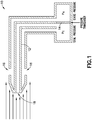
- the traditional means of air speed measurement uses a Pitot tube 10 which measures the dynamic pressure through use of a tube 12 pointed into the air flow and which measures the difference between the static pressure P s and total pressure P t through differently positioned air intakes 16 and 18, together with a fluid measurement using a pressure transducer 14 as shown in FIG. 1 .
- MEMS pressure transducers generate an electrical signal output that is in some way proportional to the applied pressure of a given medium.
- the application disclosed herein employs one or more differential pressure sensors, which will measure the difference between the outer air flow pressure in an air channel and the static pressure inside the conformal surface. The ability to detect small pressure changes makes MEMS differential pressure sensors ideal for applications which must translate small pressure differences into accurate air speed measurements.
- MEMS pressure sensors There are also different technologies used for MEMS pressure sensors.
- the most common type of MEMS pressure sensor is based on piezoresistive technology, which implements a strain gage that experiences a change in resistivity when exposed to physical pressure stimuli, i.e., the strain force in an ion-implanted resistor over a diaphragm.
- these sensors are inherently sensitive to temperature changes, making their use on aircraft problematic.
- the other common technology used is capacitive.
- a capacitive differential pressure sensor measures changes in pressure by the deflection of a deformable conductive diaphragm due to the applied pressure.
- a capacitive differential pressure sensor is based on two conductive electrodes with a small gap between them. One of the conductive electrodes is movable relative to the other in response to changing pressure differential. The electrical field (and capacitance) will change linearly as a function of the distance between the two electrodes. The smaller the gap, the higher the capacitance value until they touch and short-circuit the capacitor. Capacitive sensors are also insensitive to temperature effects, which is a great advantage over the piezoelectric versions. In accordance with the embodiments disclosed herein, MEMS capacitive differential pressure sensors are employed.
- FIG. 2 A cross section of a MEMS capacitive differential pressure sensor 20 in accordance with one embodiment is shown in FIG. 2 .
- This sensor comprises a silicon substrate (i.e., base) 22, a peripheral wall 24 which extends upward from the substrate 22, and a deformable diaphragm membrane 30 having a peripheral portion attached to the peripheral wall 24.
- the volume of space bounded by substrate 22, peripheral wall 24, and diaphragm membrane 30 forms a cavity 26 which, as explained in more detail below, will be occupied by air at a static pressure.
- the diaphragm membrane 30 is shown in an undeformed state, meaning that the internal and external pressures (indicated in FIG. 2 by respective sets of opposing arrows) acting on the opposites sides of the membrane are equal.
- the MEMS capacitive differential pressure sensor 20 depicted in FIG. 2 further comprises a bottom electrode 28 formed on the upper surface of the substrate 22 and a top electrode 32 formed on the inner (i.e., lower as seen in FIG. 2 ) surface of the diaphragm membrane 30. Both electrodes are made of electrically conductive material. As will be described in more detail later with reference to FIG. 3B , during flight of the aircraft the outer (i.e., upper as seen in FIG.
- the operation of the MEMS capacitive differential pressure sensor 20 depicted in FIG. 2 during flight of the aircraft on which it is mounted, will be briefly described here.
- the internal pressure i.e., the pressure inside cavity 26
- the top electrode 32 deflects towards the bottom electrode 28 and the effective capacitance increases.
- the electrical field (and capacitance) will change linearly as a function of the distance between the two electrodes. The smaller the gap, the higher the capacitance value.
- the air speed can be estimated based in part on such changes in capacitance, which changes in capacitance are in turn a function of the pressure difference across the diaphragm membrane 30.
- MEMS pressure sensors are calibrated by applying one pressure while capturing the raw data from the pressure sensor and an accurate measurement from a high-accuracy NIST (National Institute of Standards and Technology) calibrated reference sensor. This sequence is repeated for many pressure set points and the captured sensor data are then run through a compensation algorithm to determine a linear fit for the sensor output. Calibration coefficients, such as offset and gain, are calculated in this process.
- the air speed measuring system disclosed herein uses integrated devices in which these coefficients are stored in onboard non-volatile memory to very accurately report a measured pressure which has been fully compensated for external factors. These pressure values can then be communicated to an air speed processor, as will be described in detail later with reference to FIGS. 4 and 6 .
- Miniaturized capacitive sensors such as MEMS-based sensors, have one potential problem, that is, parasitic effects such as environmental noise, parasitic capacitance and leakage resistance. These effects are much less pronounced for piezoresistive devices. These parasitic effects are inherently related to miniaturization in the case of a capacitive device. Downscaling of the sensor dimensions implies downscaling of the active capacitance values to a few femtofarads. Hence, high output impedance and noise sensitivity cannot be avoided and the effects of stray capacitance becomes more dominant. Thus, signal conditioning must be done in close proximity to the pressure sensor, i.e., within the sensor package itself.
- the conformal air speed sensors in accordance with the embodiments disclosed herein further comprise a partially flexible conformal surface structure with air channels and holes for MEMS capacitive differential pressure sensor input as well as static air intake.
- the conformal surface 40 is made of a flexible material, such a metal or a plastic.
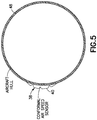
- the flexible conformal surface 40 of the conformal air speed sensor 38 (with multiple air channels) can be positioned on the curved surface 48 of an airplane fuselage (i.e., hull) with the air channels positioned so that the air stream flows parallel to the air channel direction to ensure correct measurement of air speed.
- the flexibility of the conformal surface 40 allows the conformal air speed sensor 38 to conform to the contour of the exterior surface 48 of the aircraft fuselage.
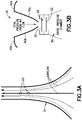
- FIG. 3A shows a top view of a portion of an air channel 34 with a pair of placed MEMS capacitive differential pressure sensors 20 in accordance with one embodiment.
- one pressure sensor or more than two pressure sensors can be placed in each air channel.
- the arrows in FIG. 3A represent airflow through the air channel 34, with thicker arrows representing higher air velocity. The air velocity decreases parabolically with increasing distance from the center of the air channel 34 to zero.
- the MEMS capacitive differential pressure sensors 20 are positioned so that the maximum differential pressure falls within the sensor range but with minimal turbulence.
- FIG. 3B represents a sectional view of the air channel 34 depicted in FIG. 3A , the section line being taken through the center of a MEMS capacitive differential pressure sensor 20.
- the air channel 34 is formed in the conformal surface. Portions 40a through 40d of a conformal surface are shown in FIG. 3B , wherein exterior portions 40a and 40d form part of the exterior of the conformal surface, and air channel wall portions 40b and 40c form a pair of walls of the channel 34.
- the air channel 34 is designed with air channel wall portions 40b and 40c that restrict the air flow in a designed manner such that when the width of the air channel 34 is decreased, the air velocity increases and hence the air pressure decreases at certain designed locations.
- the air channels can even use multiple reduction stages as well as other shape manipulations such as small ridges or dimples that not only reduce air flow velocity, but also reduce or change air turbulence to help with consistent air pressure measurement.
- a MEMS capacitive differential pressure sensor is indicated symbolically by a pair of horizontal lines respectively representing the diaphragm membrane 30 (with top electrode 32 not shown) and the silicon substrate 22 (with bottom electrode 28 not shown).
- the air channel 34 is occupied by air flow having a total pressure, which air flow is in fluid communication with a space above the diaphragm membrane 30.
- the cavity 26 between diaphragm membrane 30 and silicon substrate 22 is in fluid communication with a respective static pressure chamber 36.
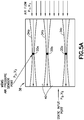
- FIG. 5A is a diagram representing a top view of a MEMS-based conformal air speed sensor 38 comprising a conformal surface 40 having three air channels 34a-34c.
- air flow at a pressure P 1 and a velocity V 1 enters the air channels at the forward end of the air speed sensor 38, as indicated by a set of parallel arrows on the right-hand side of FIG. 5A .
- Each of the air channels 34a-34c has a constriction.
- a respective port is provided in the bottom of each air channel at the respective constriction.
- Respective MEMS air pressure sensors 20a-20c are installed below these ports.
- the air speed sensor 38 further comprises one or more static input ports (not visible in FIG. 5A ) at the back end of the air speed sensor. These static input ports are in fluid communication with the static pressure chambers 36a-36c shown in FIG. 6 .
- the ambient air entering the static input ports has a pressure P S and a velocity V S .
- FIG. 5B is a diagram representing a sectional view of the MEMS-based conformal air speed sensor 38 depicted in FIG. 5A , the section being taken through the MEMS pressure sensors 20a-20c which lie below respective air channels 34a-34c.
- the conformal air speed sensor 38 comprises a conformal surface 40 and a backside surface 42 connected by a multiplicity of interior ribs 44, which structures are made of flexible plastic material.
- the interior spaces of the conformal air speed sensor 38 depicted in FIG. 5B may be filled with thermal gel 46 for heating purposes, as explained in detail below.
- the conformal air speed sensor 38 is tapered on both sides and at the leading and trailing edges thereof.
- the MEMS pressure sensors 20a-20c shown in FIG. 5B are in fluid communication with a static pressure channel 35, which may in turn be in fluid communication with a plurality of static pressure chambers (not shown in FIG. 5B ) similar in structure to static pressure chambers 36a-36c shown in FIG. 6 .
- FIG. 6 depicts components of a conformal air speed sensor having a conformal surface made of metal in accordance with an alternative embodiment.
- the upper portion of FIG. 6 represents a sectional view (not drawn to scale; exaggerated in depth) of a conformal surface equipped with a plurality of MEMS pressure sensors 20a-20c (not showing curved tapered shape as mounted), while the lower portion of FIG. 6 is a block diagram showing associated electrical components.
- the conformal surface 40 and the backside surface 42 (as well as a plurality of interior ribs not shown) are made of a flexible metal.
- the conformal surface 40 is formed with three air channels 34a-34c.
- the section is taken in a plane that passes through the plurality of MEMS pressure sensors 20a-20c in the constricted regions of the respective air channels 34a-34c.
- the conformal air speed sensor depicted in FIG. 6 further comprises a plurality of static pressure chambers 36a-36c disposed underneath respective MEMS pressure sensors 20a-20c.
- the static pressure chambers 36a-36c are in fluid communication with each other via static pressure channels 35a and 35b.
- a multiplicity of resistive heating wires 58 are attached to the metallic conformal surface 40 for heating purposes, as described in detail below.
- the analog signals from each of the MEMS differential pressure sensors 20a-20c are conditioned by a respective MEMS differential pressure signal conditioning circuit 60.
- the conditioned analog signals are then converted into digital signals by an analog-to-digital converter 62.
- the system further comprises an air speed sensor digital processor 64 that processes the digital signals. This digital processing includes determining the changes in capacitance of the plurality of MEMS differential pressure sensors 20a-20c and computing a final air speed estimate.
- Calibration coefficients, such as offset and gain, are stored in non-volatile memory 66, which calibration coefficients are used by the air speed sensor digital processor 64 to very accurately report a measured pressure which has been fully compensated for external factors.
- the electronic circuitry depicted in FIG. 6 is powered by an electrical power supply 68, which in turn receives electrical power from the aircraft.
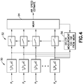
- FIG. 4 is a block diagram showing the redundant air speed processing.
- the air speed sensor digital processor takes the corrected differential air pressure measurements P 1 through P n (either in analog or digital form) from the array of n MEMS sensors and produces a single air speed estimate.
- To make an accurate estimate requires closely coupling the air speed calculation with a computational fluid dynamics (CFD) simulation that produces the pressure field at the location of each MEMS sensor under specific air flow conditions.
- CFD computational fluid dynamics
- the air speed sensor digital processor then implements these transforms on the differential pressure measurements from MEMS pressure sensor by throwing out outliers to produce a more accurate mean value of the final air speed estimate.
- the details are shown in the block diagram of FIG. 4 .
- the air speed sensor digital processor receives the differential pressure measurements P 1 through P n from the first through n-th MEMS pressure sensors and applies the transforms in step 50 to produce respective air speed estimates. These air speed estimates are output to switches 52 and, if those switches are open, received and processed by a software module 54 that computes the mean of the respective air speed estimates for each set during successive intervals of time. The resulting mean values are output as successive air speed estimates over time.
- the state of the switches 52 is controlled by a switch control circuit 56 that is configured to delete air speed estimates which are too far from the previous mean air speed estimate, thereby filtering out outlier values.
- the conformal surface can be heated. Since the conformal surface structure is flexible to accommodate mounting on aircraft with varying external curvature on its surfaces, the surface heating should not interfere with that flexibility. The following two options may be employed:
- ⁇ 2 V 2 P total ⁇ P static
- ⁇ is the air density at a given altitude
- V is the air flow speed at a given point on a streamline
- P static is the static air pressure of the aircraft under the particular atmospheric weather conditions
- P total is the total air pressure experienced as a result of the air flow caused by the motion of the aircraft.
- the total air pressure can be significantly higher than the static atmospheric pressure when an aircraft is traveling at 600 mph or 269 meters per second (m/sec), as is quite typical during most of an airliner's cruise phase.
- the MEMS pressure sensor has a pressure range 0 to R kPa.
- the result is the air speed resolution estimate (as a function of air speed) shown in FIG. 7 .
- the air channel design must reduce the total pressure by a factor of 3X at 300 m/sec to place the total pressure within the range of the pressure sensor.
- the principle of operation of the devices disclosed herein is a modification of the Venturi effect for measuring flow in liquids and gases.
- the Venturi effect is based on using a "funnel" to constrain the flow of fluid.
- a fluid's velocity must increase as it passes through a constriction to satisfy the principle of continuity.
- its pressure must decrease to satisfy the principle of conservation of mechanical energy.
- any gain of the fluid's kinetic energy due to its increased velocity through a constriction is negated by a drop in its pressure.
- This principle is used to create Venturi meters to measure volumetric flow rate. This effect is modified by only having a partially constrained flow as shown in FIGS. 3A and 5A , so that this effect is reduced, but still present.
- a near conformal shape should be designed with air channels formed in the conformal surface to constrain the air flow transverse to the conformal surface, but not perpendicular to the conformal surface.
- This "open-air Venturi surface” has been studied in other contexts, such as with constrained building configurations.
- By designing a near-conformal air speed sensor surface with restrictive channel shapes as shown in FIGS. 3A and 5A one can increase the air velocity amplification factor K to a designated value. This may be done using one or more designed channel restrictions in series. By increasing the air flow rate, the pressure can be decreased by the same factor. Thus one can achieve (for example) the 3X reduction mentioned in the example disclosed above. From measurements within the air channels, a final air speed velocity can be estimated. This is explained mathematically below.
- V 2 P 2 ⁇ P s ⁇ / 2
- MEMS-based conformal air speed sensor In summary, the concept of a MEMS-based conformal air speed sensor has been disclosed to address the icing and blockage problems inherent in standard Pitot tube air speed sensors.
- This MEMS-based conformal air speed sensor channels air flow over its channeled surface and measures relative air pressure between the air flowing in the channel and the static pressure under the channel to estimate the air speed of an aircraft.
- the conformal surface structure is made of flexible material and can be attached to the side or bottom of an aircraft as an adjunct or main air speed sensor.
Landscapes
- Physics & Mathematics (AREA)
- General Physics & Mathematics (AREA)
- Engineering & Computer Science (AREA)
- Aviation & Aerospace Engineering (AREA)
- Fluid Mechanics (AREA)
- Measuring Fluid Pressure (AREA)
Claims (14)
- Vorrichtung zur Erzeugung eines Differenzdruck-Signals für eine Fluggeschwindigkeitsmessung für ein Luftfahrzeug, wobei die Vorrichtung umfasst:eine flexible Struktur, die dazu ausgerichtet ist, derart an einer gekrümmten Oberfläche (48) des Rumpfes eines Flugzeugs angeordnet zu sein, dass sie der Kontur der äußeren Oberfläche des Rumpfes entspricht, wobei die flexible Struktur eine äußere Oberfläche mit einem darin ausgeformten ersten offenen Luftkanal (34; 34a) aufweist; undeinen ersten Drucksensor (20; 20a), der in der flexiblen Struktur an einer Position unterhalb des ersten offenen Luftkanals (34; 34a) angebracht ist und mit diesem in Flüssigkeitsverbindung steht;wobei die flexible Struktur einen statischen Druckeingang und eine statische Druckkammer (36; 36a) in Flüssigkeitsverbindung mit dem statischen Druckeingang umfasst, wobei der erste Drucksensor (20; 20a) in Flüssigkeitsverbindung mit der statischen Druckkammer (36; 36a) steht.
- Vorrichtung gemäß Anspruch 1, wobei die äußere Oberfläche der flexiblen Struktur einen darin ausgeformten zweiten offenen Luftkanal (34b, 34c) aufweist, und wobei die Vorrichtung weiterhin einen zweiten Drucksensor (20b, 20c) umfasst, der in der flexiblen Struktur an einer Position unterhalb des zweiten offenen Luftkanals (34b, 34c) angebracht ist und mit diesem und einer zweiten statischen Druckkammer (36b, 36c) in Flüssigkeitsverbindung steht.
- Vorrichtung gemäß Anspruch 1 oder 2, wobei es sich bei dem ersten und/oder dem zweiten Drucksensor (20; 20a-c) um einen kapazitiven Differenzdrucksensor handelt, der ein mikro-elektromechanisches System umfasst, und/oder wobei der erste und/oder der zweite Drucksensor (20; 20a-c) eine verformbare Diaphragma-Membran (30) mit einer darauf ausgeformten ersten Elektrode (32) und ein Substrat (22) mit einer darauf ausgeformten zweiten Elektrode (28) aufweist, wobei die erste und die zweite Elektrode (32, 28) durch einen Abstand voneinander getrennt sind, bei dem es sich um eine Funktion einer Ablenkung der verformbaren Diaphragma-Membran (30) handelt.
- Vorrichtung gemäß einem der vorangegangenen Ansprüche, wobei der erste und/oder der zweite offene Luftkanal (34; 34a-c) einen verengten Abschnitt umfassen, wobei der erste und/oder der zweite Drucksensor (20; 20a-c) unterhalb des verengten Abschnitts des ersten und/oder des zweiten offenen Luftkanals (34; 34a-c) angeordnet sind.
- Vorrichtung gemäß einem der Ansprüche 2 bis 4, die weiterhin umfasst:einen ersten Signalaufbereitungsschaltkreis (60), der dazu verbunden ist, eine von dem ersten Drucksensor (20; 20a) stammende analoge Signalausgabe zu konditionieren;einen ersten Analog-Digital-Wandler (62), der dazu verbunden ist, eine von dem ersten Signalaufbereitungsschaltkreis (60) stammende aufbereitete analoge Signalausgabe in ein erstes digitales Signal umzuwandeln;einen zweiten Signalaufbereitungsschaltkreis (60), der dazu verbunden ist, eine von dem zweiten Drucksensor (20b; 20c) stammende analoge Signalausgabe zu konditioniere;einen zweiten Analog-Digital-Wandler (62), der dazu verbunden ist, eine von dem zweiten Signalaufbereitungsschaltkreis (60) stammende aufbereitete analoge Signalausgabe in ein zweites digitales Signal umzuwandeln; undeinen Prozessor (64), der dazu programmiert ist, unter Berücksichtigung des ersten und des zweiten digitalen Signals eine Fluggeschwindigkeitsschätzung zu berechnen.
- Vorrichtung gemäß einem der vorangegangenen Ansprüche, die weiterhin ein Heizelement (58) umfasst, und optional ein thermisch leitfähiges Gel (46) umfasst, über welches das Heizelement thermisch mit der äußeren Oberfläche der flexiblen Struktur verbunden ist, wobei die äußere Oberfläche der flexiblen Struktur optional aus Metall oder aus Kunststoff hergestellt ist.
- System, das umfasst: ein Flugzeug mit einer äußeren Oberfläche (48) und einem entsprechenden Fluggeschwindigkeitssensor (38), der an der äußeren Oberfläche des Flugzeugs befestigt ist, wobei der entsprechende Fluggeschwindigkeitssensor (38) umfasst:eine Vorrichtung gemäß Anspruch 2, wobei es sich bei dem ersten und/oder dem zweiten Drucksensor (20; 20a-c) um kapazitive Differenzdrucksensoren handelt; undeine elektronische Schaltung, die dazu programmiert oder konfiguriert ist, eine Fluggeschwindigkeit (V1) des Flugzeugs wenigstens zum Teil basierend auf von dem ersten und dem zweiten kapazitiven Differenzdrucksensor ausgegebenen Signalen zu schätzen.
- System gemäß Anspruch 7, wobei die flexible Struktur einen statischen Druckeingang sowie eine erste und eine zweite statische Druckkammer (36; 36a-c) in Flüssigkeitsverbindung mit dem statischen Druckeingang umfasst, wobei der erste Drucksensor (20; 20a) zwischen dem ersten offenen Luftkanal (34; 34a) und der ersten statischen Druckkammer (36; 36a) angeordnet ist, und wobei der zweite Drucksensor (20b; 20c) zwischen dem zweiten offenen Luftkanal (34b; 34c) und der zweiten statischen Druckkammer (36b; 36c) angeordnet ist.
- System gemäß den Ansprüchen 7 und 8, wobei der erste und der zweite kapazitive Differenzdrucksensor jeweils eine verformbare Diaphragma-Membran (30) mit einer darauf ausgeformten ersten Elektrode (32) und ein Substrat (22) mit einer darauf ausgeformten zweiten Elektrode (28) aufweisen, wobei die erste und die zweite Elektrode (32, 28) durch einen Abstand voneinander getrennt sind, bei dem es sich um eine Funktion einer Ablenkung der verformbaren Diaphragma-Membran (30) handelt.
- System gemäß den Ansprüchen 7 bis 9, wobei der erste und der zweite offene Luftkanal (34; 34a-c) jeweils einen verengten Abschnitt umfassen, wobei der erste kapazitive Differenzdrucksensor unterhalb des verengten Abschnitts des ersten offenen Luftkanals (34; 34a) angeordnet ist, und der zweite kapazitive Differenzdrucksensor unterhalb des verengten Abschnitts des zweiten offenen Luftkanals (34b; 34c) angeordnet ist.
- System gemäß den Ansprüchen 7 bis 10, wobei die elektronische Schaltung umfasst:einen ersten Signalaufbereitungsschaltkreis (60), der dazu verbunden ist, eine von dem ersten kapazitiven Differenzdrucksensor stammende analoge Signalausgabe aufzubereiten;einen ersten Analog-Digital-Wandler (62), der dazu verbunden ist, eine von dem ersten Signalaufbereitungsschaltkreis (60) stammende aufbereitete analoge Signalausgabe in ein erstes digitales Signal umzuwandeln;einen zweiten Signalaufbereitungsschaltkreis (60), der dazu verbunden ist, eine von dem zweiten kapazitiven Differenzdrucksensor stammende analoge Signalausgabe aufzubereiten;einen zweiten Analog-Digital-Wandler (62), der dazu verbunden ist, eine von dem zweiten Signalaufbereitungsschaltkreis (60) stammende aufbereitete analoge Signalausgabe in ein zweites digitales Signal umzuwandeln; undeinen Prozessor (64), der dazu programmiert ist, unter Berücksichtigung des ersten und des zweiten digitalen Signals eine Fluggeschwindigkeitsschätzung zu berechnen.
- System gemäß den Ansprüchen 7 bis 11, das weiterhin ein Heizelement (58) umfasst, und optional ein thermisch leitfähiges Gel (46) umfasst, über welches das Heizelement (58) thermisch mit der äußeren Oberfläche der flexiblen Struktur verbunden ist, wobei die äußere Oberfläche der flexiblen Struktur optional aus Metall oder aus Kunststoff hergestellt ist.
- Verfahren zur Schätzung der Geschwindigkeit eines Flugzeugs, das dazu betriebsfähig ist, sich durch ein flüssiges Medium zu bewegen, wobei die Vorrichtung gemäß einem der Ansprüche 1 bis 6 verwendet wird, wobei das Verfahren umfasst:Befestigen eines flexiblen Struktur der Vorrichtung an einer äußeren Oberfläche (48) des Flugzeugs, wobei die flexible Struktur eine äußere Oberfläche aufweist, in der wenigstens ein offener Kanal (34; 34a-c) für das flüssige Medium ausgeformt ist;Übertragen von Signalen durch den wenigstens einen unterhalb der verengten Abschnitte des wenigstens einen offenen Flüssigmediumkanals (34; 34a-c) angebrachten Differenzdrucksensor (34; 34a-c); undBerechnen der Geschwindigkeit (V1) des Flugzeugs relativ zu einem es umgebenden flüssigen Medium während der Bewegung des Flugzeugs, wobei die Berechnung der Geschwindigkeit auf einer Dichte (p) des flüssigen Mediums und auf den von dem wenigstens einen Differenzdrucksensor (20; 20a-c) übertragenen Signalen basiert.
- Verfahren gemäß Anspruch 13, wobei jedes von jedem Differenzdrucksensor (20; 20a-c) übertragene Signal eine Differenz zwischen einem statischen Druck (Pstatic) unter einem jeweiligen offenen Flüssigmediumkanal (34; 34a-c) und einem Gesamtdruck (Ptotal) in dem offenen Flüssigmediumkanal (34; 34a-c) darstellt.
Priority Applications (1)
| Application Number | Priority Date | Filing Date | Title |
|---|---|---|---|
| EP18160100.6A EP3379258A1 (de) | 2014-06-30 | 2015-06-30 | Mems-basierter konformer luftgeschwindigkeitssensor |
Applications Claiming Priority (1)
| Application Number | Priority Date | Filing Date | Title |
|---|---|---|---|
| US14/318,955 US9322685B2 (en) | 2014-06-30 | 2014-06-30 | MEMS-based conformal air speed sensor |
Related Child Applications (3)
| Application Number | Title | Priority Date | Filing Date |
|---|---|---|---|
| EP18160100.6A Division-Into EP3379258A1 (de) | 2014-06-30 | 2015-06-30 | Mems-basierter konformer luftgeschwindigkeitssensor |
| EP18160100.6A Division EP3379258A1 (de) | 2014-06-30 | 2015-06-30 | Mems-basierter konformer luftgeschwindigkeitssensor |
| EP18160100.6A Previously-Filed-Application EP3379258A1 (de) | 2014-06-30 | 2015-06-30 | Mems-basierter konformer luftgeschwindigkeitssensor |
Publications (2)
| Publication Number | Publication Date |
|---|---|
| EP2963425A1 EP2963425A1 (de) | 2016-01-06 |
| EP2963425B1 true EP2963425B1 (de) | 2018-04-11 |
Family
ID=53491408
Family Applications (2)
| Application Number | Title | Priority Date | Filing Date |
|---|---|---|---|
| EP18160100.6A Withdrawn EP3379258A1 (de) | 2014-06-30 | 2015-06-30 | Mems-basierter konformer luftgeschwindigkeitssensor |
| EP15174480.2A Active EP2963425B1 (de) | 2014-06-30 | 2015-06-30 | Mems-basierter konformer luftgeschwindigkeitssensor |
Family Applications Before (1)
| Application Number | Title | Priority Date | Filing Date |
|---|---|---|---|
| EP18160100.6A Withdrawn EP3379258A1 (de) | 2014-06-30 | 2015-06-30 | Mems-basierter konformer luftgeschwindigkeitssensor |
Country Status (6)
| Country | Link |
|---|---|
| US (1) | US9322685B2 (de) |
| EP (2) | EP3379258A1 (de) |
| JP (1) | JP6389139B2 (de) |
| CN (1) | CN105319388B (de) |
| BR (1) | BR102015011126B1 (de) |
| RU (1) | RU2620876C2 (de) |
Families Citing this family (35)
| Publication number | Priority date | Publication date | Assignee | Title |
|---|---|---|---|---|
| WO2014116205A1 (en) * | 2013-01-22 | 2014-07-31 | Mingqiang Yi | A mems chip for wind speed measurements |
| US9631996B2 (en) | 2014-07-03 | 2017-04-25 | Infineon Technologies Ag | Motion detection using pressure sensing |
| US9574960B2 (en) * | 2014-07-09 | 2017-02-21 | Kulite Semiconductor Products, Inc. | Ultra-miniature multi-hole flow angle probes |
| US9945884B2 (en) * | 2015-01-30 | 2018-04-17 | Infineon Technologies Ag | System and method for a wind speed meter |
| US10324104B2 (en) | 2016-01-04 | 2019-06-18 | Bradley Charles Ashmore | Device for measuring the speed and direction of a gas flow |
| US10768201B2 (en) * | 2017-06-12 | 2020-09-08 | The Boeing Company | System for estimating airspeed of an aircraft based on a drag model |
| CN107328953A (zh) * | 2017-06-28 | 2017-11-07 | 西安交通大学 | 一种改进型狭窄通道内流动测量装置 |
| CN111433612B (zh) * | 2017-10-11 | 2023-10-13 | 埃姆普里萨有限公司 | 用于估计飞行器空中数据的基于模型和飞行信息的组合训练的神经网络系统 |
| CN108169821A (zh) * | 2018-02-02 | 2018-06-15 | 顺丰科技有限公司 | 一种大气数据测量装置 |
| US12253391B2 (en) | 2018-05-24 | 2025-03-18 | The Research Foundation For The State University Of New York | Multielectrode capacitive sensor without pull-in risk |
| CN109974926B (zh) * | 2019-05-06 | 2024-03-01 | 深圳市湃科集成技术有限公司 | 多档位输出压差传感器 |
| CN110470859B (zh) * | 2019-09-24 | 2021-04-20 | 西北工业大学 | 一种用于空气系统内气流方向速度测量的方法 |
| CN112649621B (zh) * | 2019-10-11 | 2024-05-14 | 上海峰飞航空科技有限公司 | 一体式加热空速管及包含其的无人机 |
| CN111076848A (zh) * | 2019-12-27 | 2020-04-28 | 天津大学 | 一种压力测量装置及方法 |
| CN113188541B (zh) * | 2020-01-14 | 2025-04-01 | 广州极飞科技股份有限公司 | 获取无人机的空速的方法、装置、存储介质及处理器 |
| US11181544B2 (en) | 2020-02-20 | 2021-11-23 | Bradley Charles Ashmore | Configurable flow velocimeter |
| CN111308113B (zh) * | 2020-02-25 | 2025-09-23 | 中山福昆航空科技有限公司 | 一种磁吸式快卸空速管装置及待测空速设备 |
| US11525840B2 (en) * | 2020-04-16 | 2022-12-13 | Government Of The United States Of America, As Represented By The Secretary Of Commerce | Non-nulling gas velocity measurement apparatus and performing non-nulling measurement of gas velocity parameters |
| CN111551218B (zh) * | 2020-05-18 | 2021-11-09 | 重庆市科学技术研究院 | 一种皮托管流量测定仪 |
| CN111551219B (zh) * | 2020-05-18 | 2021-11-09 | 重庆市科学技术研究院 | 一种皮托管结构 |
| WO2022064095A1 (en) * | 2020-09-22 | 2022-03-31 | Teconer Oy | Wind speed measurement |
| ES1266233Y (es) * | 2021-01-19 | 2021-07-28 | Albina Lopez De Armentia Inigo | Racor para medida de caudales y volúmenes y detección de consumo en hidrantes, bocas de riego o cualquier tipo de toma |
| US11686638B2 (en) | 2021-05-08 | 2023-06-27 | The Boeing Company | Piezoelectric sensor having a membrane made of auxetic metamaterial for enhanced sensitivity |
| US11702958B2 (en) | 2021-09-23 | 2023-07-18 | General Electric Company | System and method of regulating thermal transport bus pressure |
| US12410752B2 (en) | 2021-09-23 | 2025-09-09 | General Electric Company | System and method of detecting an airflow fault condition |
| CN114675051B (zh) * | 2022-03-08 | 2022-10-28 | 中国水利水电科学研究院 | 一种基于压差测量的河流流速监测装置、系统和方法 |
| EP4296689B1 (de) | 2022-06-21 | 2026-01-21 | Airbus SAS | Pitotrohr-sensorvorrichtung |
| CN115406574A (zh) * | 2022-08-18 | 2022-11-29 | 中国航空工业集团公司北京长城计量测试技术研究所 | 基于速度计算的大空间微小差压测量装置 |
| CN115575661B (zh) * | 2022-10-13 | 2025-03-04 | 东南大学 | 二维电容差分式mems风速风向传感器 |
| CN115656548B (zh) * | 2022-11-09 | 2023-07-21 | 湖南大学 | 一种mems气流传感器 |
| CN115856351B (zh) * | 2022-11-17 | 2025-09-09 | 中国直升机设计研究所 | 一种基于三差压测量的双向空速测量装置及方法 |
| CN115792272B (zh) * | 2022-12-08 | 2025-10-21 | 南京航空航天大学 | 一种亚音速飞行器空速测量方法和系统 |
| CN117723771B (zh) * | 2023-12-15 | 2024-10-15 | 清华大学深圳国际研究生院 | 一种软体机器鱼的测速方法及软体机器鱼 |
| CN118294692B (zh) * | 2024-04-11 | 2024-12-13 | 中国科学院空天信息创新研究院 | 飞行器风速仪数据的解算方法和系统 |
| CN121276087A (zh) * | 2025-09-28 | 2026-01-06 | 上海交通大学 | 一种基于差压测量的mems液体流速传感器及其制备方法 |
Family Cites Families (14)
| Publication number | Priority date | Publication date | Assignee | Title |
|---|---|---|---|---|
| US3364741A (en) * | 1965-10-22 | 1968-01-23 | Aeroflex Lab Inc | Linear air-speed sensor |
| US3427878A (en) | 1968-01-18 | 1969-02-18 | Leopold Co Inc F B | Portable liquid measurement flume |
| US3795145A (en) | 1972-03-23 | 1974-03-05 | Sperry Rand Corp | Variable throat venturi airspeed sensor |
| JPS5129961A (ja) * | 1974-02-04 | 1976-03-13 | Tokyo Daigaku | Ryusokukei |
| US4458137A (en) * | 1981-04-09 | 1984-07-03 | Rosemount Inc. | Electric heater arrangement for fluid flow stream sensors |
| JPS6128061U (ja) * | 1984-07-26 | 1986-02-19 | 横河電機株式会社 | 気体流速計 |
| US6101429A (en) | 1998-04-07 | 2000-08-08 | Tao Of Systems Integration, Inc. | Broad-range, multi-directional aircraft airspeed measuring system |
| US6820490B2 (en) * | 2001-10-16 | 2004-11-23 | Neomedix Corporation | Systems and methods for measuring pressure |
| DE102005052929B4 (de) * | 2005-11-03 | 2011-07-21 | Eurocopter Deutschland GmbH, 86609 | Sensor für ein Luftfahrzeug, insbesondere ein Flugzeug oder Hubschrauber |
| US7337678B2 (en) | 2005-12-09 | 2008-03-04 | General Electric Company | MEMS flow sensor |
| US7508040B2 (en) * | 2006-06-05 | 2009-03-24 | Hewlett-Packard Development Company, L.P. | Micro electrical mechanical systems pressure sensor |
| WO2008027996A2 (en) * | 2006-08-29 | 2008-03-06 | California Institute Of Technology | Microfabricated implantable wireless pressure sensor for use in biomedical applications and pressure measurement and sensor implantation methods |
| US7654157B2 (en) | 2007-11-30 | 2010-02-02 | Honeywell International Inc. | Airflow sensor with pitot tube for pressure drop reduction |
| TWI362488B (en) * | 2008-02-13 | 2012-04-21 | Ind Tech Res Inst | Transistor type pressure sensor and method for making the same |
-
2014
- 2014-06-30 US US14/318,955 patent/US9322685B2/en active Active
-
2015
- 2015-03-30 RU RU2015111359A patent/RU2620876C2/ru active
- 2015-04-02 JP JP2015075698A patent/JP6389139B2/ja active Active
- 2015-05-14 BR BR102015011126-6A patent/BR102015011126B1/pt active IP Right Grant
- 2015-06-30 EP EP18160100.6A patent/EP3379258A1/de not_active Withdrawn
- 2015-06-30 EP EP15174480.2A patent/EP2963425B1/de active Active
- 2015-06-30 CN CN201510379338.7A patent/CN105319388B/zh active Active
Non-Patent Citations (1)
| Title |
|---|
| None * |
Also Published As
| Publication number | Publication date |
|---|---|
| JP6389139B2 (ja) | 2018-09-12 |
| JP2016014651A (ja) | 2016-01-28 |
| CN105319388B (zh) | 2019-05-07 |
| US9322685B2 (en) | 2016-04-26 |
| EP2963425A1 (de) | 2016-01-06 |
| US20150377662A1 (en) | 2015-12-31 |
| BR102015011126B1 (pt) | 2021-01-05 |
| RU2620876C2 (ru) | 2017-05-30 |
| CN105319388A (zh) | 2016-02-10 |
| BR102015011126A2 (pt) | 2017-09-26 |
| RU2015111359A (ru) | 2016-10-20 |
| EP3379258A1 (de) | 2018-09-26 |
Similar Documents
| Publication | Publication Date | Title |
|---|---|---|
| US9322685B2 (en) | MEMS-based conformal air speed sensor | |
| Gracey | Measurement of aircraft speed and altitude | |
| EP1948330B1 (de) | Multifunktionsluftdatensensor | |
| Bruschi et al. | Wind speed and direction detection by means of solid-state anemometers embedded on small quadcopters | |
| AU2014339084B2 (en) | Air data sensor for an aircraft | |
| JP2016014651A5 (de) | ||
| Puttkammer | Boundary layer over a flat plate | |
| Aboelezz et al. | Wind tunnel calibration, corrections and experimental validation for fixed-wing micro air vehicles measurements | |
| EP3543659A1 (de) | Luftmassenmesser mit absolutdruckausgleich | |
| AU5836594A (en) | Aerodynamic pressure sensor systems | |
| Dong et al. | Ultrathin flexible skin with all-polyimide pressure and airflow sensor array for estimation of flight parameters | |
| US2352955A (en) | Angle of attack indicator | |
| US20250180596A1 (en) | Wind speed and direction measurement system and device | |
| Svedin et al. | A lift force sensor with integrated hot-chips for wide range flow measurements | |
| EP2866035A1 (de) | Luftdatensensor | |
| US20070119231A1 (en) | Incidence probe | |
| EP1750134B1 (de) | Verfahren mit ratiometrischer Charakteristisierung zur Verbesserung der Messgenauigkeit in Luftdatensystemen | |
| Soldatkina et al. | Vortex sensor of aerodynamic angle and true airspeed with enhanced functionality | |
| US7415876B2 (en) | Pressure sensor system | |
| Efremova et al. | Study of Procedure Errors of the Vortex Air Data System of a Subsonic Aircraft | |
| Castano et al. | Thin film flow sensor for unmanned aerial platforms | |
| Ma et al. | A study of directional MEMS dual-fences gauge | |
| GB2519668A (en) | Air data sensor | |
| CN119935231A (zh) | 一种柔性大气参数感知系统 | |
| GALASSI et al. | Experimental and computational comparisons of Mach 6 high Reynolds number heat transfer and skin friction |
Legal Events
| Date | Code | Title | Description |
|---|---|---|---|
| PUAI | Public reference made under article 153(3) epc to a published international application that has entered the european phase |
Free format text: ORIGINAL CODE: 0009012 |
|
| 17P | Request for examination filed |
Effective date: 20150630 |
|
| AK | Designated contracting states |
Kind code of ref document: A1 Designated state(s): AL AT BE BG CH CY CZ DE DK EE ES FI FR GB GR HR HU IE IS IT LI LT LU LV MC MK MT NL NO PL PT RO RS SE SI SK SM TR |
|
| AX | Request for extension of the european patent |
Extension state: BA ME |
|
| RIN1 | Information on inventor provided before grant (corrected) |
Inventor name: RAY, GARY A. |
|
| 17Q | First examination report despatched |
Effective date: 20170222 |
|
| GRAP | Despatch of communication of intention to grant a patent |
Free format text: ORIGINAL CODE: EPIDOSNIGR1 |
|
| INTG | Intention to grant announced |
Effective date: 20171025 |
|
| GRAS | Grant fee paid |
Free format text: ORIGINAL CODE: EPIDOSNIGR3 |
|
| GRAA | (expected) grant |
Free format text: ORIGINAL CODE: 0009210 |
|
| AK | Designated contracting states |
Kind code of ref document: B1 Designated state(s): AL AT BE BG CH CY CZ DE DK EE ES FI FR GB GR HR HU IE IS IT LI LT LU LV MC MK MT NL NO PL PT RO RS SE SI SK SM TR |
|
| REG | Reference to a national code |
Ref country code: GB Ref legal event code: FG4D |
|
| REG | Reference to a national code |
Ref country code: CH Ref legal event code: EP |
|
| REG | Reference to a national code |
Ref country code: AT Ref legal event code: REF Ref document number: 988607 Country of ref document: AT Kind code of ref document: T Effective date: 20180415 |
|
| REG | Reference to a national code |
Ref country code: IE Ref legal event code: FG4D |
|
| REG | Reference to a national code |
Ref country code: DE Ref legal event code: R096 Ref document number: 602015009749 Country of ref document: DE |
|
| REG | Reference to a national code |
Ref country code: FR Ref legal event code: PLFP Year of fee payment: 4 |
|
| REG | Reference to a national code |
Ref country code: NL Ref legal event code: MP Effective date: 20180411 |
|
| REG | Reference to a national code |
Ref country code: LT Ref legal event code: MG4D |
|
| PG25 | Lapsed in a contracting state [announced via postgrant information from national office to epo] |
Ref country code: NL Free format text: LAPSE BECAUSE OF FAILURE TO SUBMIT A TRANSLATION OF THE DESCRIPTION OR TO PAY THE FEE WITHIN THE PRESCRIBED TIME-LIMIT Effective date: 20180411 |
|
| PG25 | Lapsed in a contracting state [announced via postgrant information from national office to epo] |
Ref country code: BG Free format text: LAPSE BECAUSE OF FAILURE TO SUBMIT A TRANSLATION OF THE DESCRIPTION OR TO PAY THE FEE WITHIN THE PRESCRIBED TIME-LIMIT Effective date: 20180711 Ref country code: ES Free format text: LAPSE BECAUSE OF FAILURE TO SUBMIT A TRANSLATION OF THE DESCRIPTION OR TO PAY THE FEE WITHIN THE PRESCRIBED TIME-LIMIT Effective date: 20180411 Ref country code: PL Free format text: LAPSE BECAUSE OF FAILURE TO SUBMIT A TRANSLATION OF THE DESCRIPTION OR TO PAY THE FEE WITHIN THE PRESCRIBED TIME-LIMIT Effective date: 20180411 Ref country code: LT Free format text: LAPSE BECAUSE OF FAILURE TO SUBMIT A TRANSLATION OF THE DESCRIPTION OR TO PAY THE FEE WITHIN THE PRESCRIBED TIME-LIMIT Effective date: 20180411 Ref country code: FI Free format text: LAPSE BECAUSE OF FAILURE TO SUBMIT A TRANSLATION OF THE DESCRIPTION OR TO PAY THE FEE WITHIN THE PRESCRIBED TIME-LIMIT Effective date: 20180411 Ref country code: AL Free format text: LAPSE BECAUSE OF FAILURE TO SUBMIT A TRANSLATION OF THE DESCRIPTION OR TO PAY THE FEE WITHIN THE PRESCRIBED TIME-LIMIT Effective date: 20180411 Ref country code: SE Free format text: LAPSE BECAUSE OF FAILURE TO SUBMIT A TRANSLATION OF THE DESCRIPTION OR TO PAY THE FEE WITHIN THE PRESCRIBED TIME-LIMIT Effective date: 20180411 Ref country code: NO Free format text: LAPSE BECAUSE OF FAILURE TO SUBMIT A TRANSLATION OF THE DESCRIPTION OR TO PAY THE FEE WITHIN THE PRESCRIBED TIME-LIMIT Effective date: 20180711 |
|
| PG25 | Lapsed in a contracting state [announced via postgrant information from national office to epo] |
Ref country code: RS Free format text: LAPSE BECAUSE OF FAILURE TO SUBMIT A TRANSLATION OF THE DESCRIPTION OR TO PAY THE FEE WITHIN THE PRESCRIBED TIME-LIMIT Effective date: 20180411 Ref country code: HR Free format text: LAPSE BECAUSE OF FAILURE TO SUBMIT A TRANSLATION OF THE DESCRIPTION OR TO PAY THE FEE WITHIN THE PRESCRIBED TIME-LIMIT Effective date: 20180411 Ref country code: GR Free format text: LAPSE BECAUSE OF FAILURE TO SUBMIT A TRANSLATION OF THE DESCRIPTION OR TO PAY THE FEE WITHIN THE PRESCRIBED TIME-LIMIT Effective date: 20180712 Ref country code: LV Free format text: LAPSE BECAUSE OF FAILURE TO SUBMIT A TRANSLATION OF THE DESCRIPTION OR TO PAY THE FEE WITHIN THE PRESCRIBED TIME-LIMIT Effective date: 20180411 |
|
| REG | Reference to a national code |
Ref country code: AT Ref legal event code: MK05 Ref document number: 988607 Country of ref document: AT Kind code of ref document: T Effective date: 20180411 |
|
| PG25 | Lapsed in a contracting state [announced via postgrant information from national office to epo] |
Ref country code: PT Free format text: LAPSE BECAUSE OF FAILURE TO SUBMIT A TRANSLATION OF THE DESCRIPTION OR TO PAY THE FEE WITHIN THE PRESCRIBED TIME-LIMIT Effective date: 20180813 |
|
| REG | Reference to a national code |
Ref country code: DE Ref legal event code: R097 Ref document number: 602015009749 Country of ref document: DE |
|
| PG25 | Lapsed in a contracting state [announced via postgrant information from national office to epo] |
Ref country code: RO Free format text: LAPSE BECAUSE OF FAILURE TO SUBMIT A TRANSLATION OF THE DESCRIPTION OR TO PAY THE FEE WITHIN THE PRESCRIBED TIME-LIMIT Effective date: 20180411 Ref country code: SK Free format text: LAPSE BECAUSE OF FAILURE TO SUBMIT A TRANSLATION OF THE DESCRIPTION OR TO PAY THE FEE WITHIN THE PRESCRIBED TIME-LIMIT Effective date: 20180411 Ref country code: CZ Free format text: LAPSE BECAUSE OF FAILURE TO SUBMIT A TRANSLATION OF THE DESCRIPTION OR TO PAY THE FEE WITHIN THE PRESCRIBED TIME-LIMIT Effective date: 20180411 Ref country code: DK Free format text: LAPSE BECAUSE OF FAILURE TO SUBMIT A TRANSLATION OF THE DESCRIPTION OR TO PAY THE FEE WITHIN THE PRESCRIBED TIME-LIMIT Effective date: 20180411 Ref country code: AT Free format text: LAPSE BECAUSE OF FAILURE TO SUBMIT A TRANSLATION OF THE DESCRIPTION OR TO PAY THE FEE WITHIN THE PRESCRIBED TIME-LIMIT Effective date: 20180411 Ref country code: EE Free format text: LAPSE BECAUSE OF FAILURE TO SUBMIT A TRANSLATION OF THE DESCRIPTION OR TO PAY THE FEE WITHIN THE PRESCRIBED TIME-LIMIT Effective date: 20180411 |
|
| REG | Reference to a national code |
Ref country code: CH Ref legal event code: PL |
|
| PLBE | No opposition filed within time limit |
Free format text: ORIGINAL CODE: 0009261 |
|
| STAA | Information on the status of an ep patent application or granted ep patent |
Free format text: STATUS: NO OPPOSITION FILED WITHIN TIME LIMIT |
|
| PG25 | Lapsed in a contracting state [announced via postgrant information from national office to epo] |
Ref country code: SM Free format text: LAPSE BECAUSE OF FAILURE TO SUBMIT A TRANSLATION OF THE DESCRIPTION OR TO PAY THE FEE WITHIN THE PRESCRIBED TIME-LIMIT Effective date: 20180411 Ref country code: IT Free format text: LAPSE BECAUSE OF FAILURE TO SUBMIT A TRANSLATION OF THE DESCRIPTION OR TO PAY THE FEE WITHIN THE PRESCRIBED TIME-LIMIT Effective date: 20180411 |
|
| REG | Reference to a national code |
Ref country code: BE Ref legal event code: MM Effective date: 20180630 |
|
| 26N | No opposition filed |
Effective date: 20190114 |
|
| PG25 | Lapsed in a contracting state [announced via postgrant information from national office to epo] |
Ref country code: MC Free format text: LAPSE BECAUSE OF FAILURE TO SUBMIT A TRANSLATION OF THE DESCRIPTION OR TO PAY THE FEE WITHIN THE PRESCRIBED TIME-LIMIT Effective date: 20180411 Ref country code: LU Free format text: LAPSE BECAUSE OF NON-PAYMENT OF DUE FEES Effective date: 20180630 |
|
| REG | Reference to a national code |
Ref country code: IE Ref legal event code: MM4A |
|
| PG25 | Lapsed in a contracting state [announced via postgrant information from national office to epo] |
Ref country code: LI Free format text: LAPSE BECAUSE OF NON-PAYMENT OF DUE FEES Effective date: 20180630 Ref country code: IE Free format text: LAPSE BECAUSE OF NON-PAYMENT OF DUE FEES Effective date: 20180630 Ref country code: CH Free format text: LAPSE BECAUSE OF NON-PAYMENT OF DUE FEES Effective date: 20180630 |
|
| PG25 | Lapsed in a contracting state [announced via postgrant information from national office to epo] |
Ref country code: SI Free format text: LAPSE BECAUSE OF FAILURE TO SUBMIT A TRANSLATION OF THE DESCRIPTION OR TO PAY THE FEE WITHIN THE PRESCRIBED TIME-LIMIT Effective date: 20180411 Ref country code: BE Free format text: LAPSE BECAUSE OF NON-PAYMENT OF DUE FEES Effective date: 20180630 |
|
| PG25 | Lapsed in a contracting state [announced via postgrant information from national office to epo] |
Ref country code: MT Free format text: LAPSE BECAUSE OF NON-PAYMENT OF DUE FEES Effective date: 20180630 |
|
| PG25 | Lapsed in a contracting state [announced via postgrant information from national office to epo] |
Ref country code: TR Free format text: LAPSE BECAUSE OF FAILURE TO SUBMIT A TRANSLATION OF THE DESCRIPTION OR TO PAY THE FEE WITHIN THE PRESCRIBED TIME-LIMIT Effective date: 20180411 |
|
| PG25 | Lapsed in a contracting state [announced via postgrant information from national office to epo] |
Ref country code: HU Free format text: LAPSE BECAUSE OF FAILURE TO SUBMIT A TRANSLATION OF THE DESCRIPTION OR TO PAY THE FEE WITHIN THE PRESCRIBED TIME-LIMIT; INVALID AB INITIO Effective date: 20150630 Ref country code: MK Free format text: LAPSE BECAUSE OF NON-PAYMENT OF DUE FEES Effective date: 20180411 Ref country code: CY Free format text: LAPSE BECAUSE OF FAILURE TO SUBMIT A TRANSLATION OF THE DESCRIPTION OR TO PAY THE FEE WITHIN THE PRESCRIBED TIME-LIMIT Effective date: 20180411 |
|
| PG25 | Lapsed in a contracting state [announced via postgrant information from national office to epo] |
Ref country code: IS Free format text: LAPSE BECAUSE OF FAILURE TO SUBMIT A TRANSLATION OF THE DESCRIPTION OR TO PAY THE FEE WITHIN THE PRESCRIBED TIME-LIMIT Effective date: 20180811 |
|
| P01 | Opt-out of the competence of the unified patent court (upc) registered |
Effective date: 20230516 |
|
| PGFP | Annual fee paid to national office [announced via postgrant information from national office to epo] |
Ref country code: GB Payment date: 20260629 Year of fee payment: 12 |
|
| PGFP | Annual fee paid to national office [announced via postgrant information from national office to epo] |
Ref country code: DE Payment date: 20260629 Year of fee payment: 12 |
|
| PGFP | Annual fee paid to national office [announced via postgrant information from national office to epo] |
Ref country code: FR Payment date: 20260625 Year of fee payment: 12 |