EP2963397B1 - Radarfüllstandmessgerät-neigungssystem - Google Patents
Radarfüllstandmessgerät-neigungssystem Download PDFInfo
- Publication number
- EP2963397B1 EP2963397B1 EP15174254.1A EP15174254A EP2963397B1 EP 2963397 B1 EP2963397 B1 EP 2963397B1 EP 15174254 A EP15174254 A EP 15174254A EP 2963397 B1 EP2963397 B1 EP 2963397B1
- Authority
- EP
- European Patent Office
- Prior art keywords
- hatch
- output
- tank
- angular
- inclination
- Prior art date
- Legal status (The legal status is an assumption and is not a legal conclusion. Google has not performed a legal analysis and makes no representation as to the accuracy of the status listed.)
- Active
Links
Images


Classifications
-
- G—PHYSICS
- G01—MEASURING; TESTING
- G01F—MEASURING VOLUME, VOLUME FLOW, MASS FLOW OR LIQUID LEVEL; METERING BY VOLUME
- G01F23/00—Indicating or measuring liquid level or level of fluent solid material, e.g. indicating in terms of volume or indicating by means of an alarm
- G01F23/22—Indicating or measuring liquid level or level of fluent solid material, e.g. indicating in terms of volume or indicating by means of an alarm by measuring physical variables, other than linear dimensions, pressure or weight, dependent on the level to be measured, e.g. by difference of heat transfer of steam or water
- G01F23/28—Indicating or measuring liquid level or level of fluent solid material, e.g. indicating in terms of volume or indicating by means of an alarm by measuring physical variables, other than linear dimensions, pressure or weight, dependent on the level to be measured, e.g. by difference of heat transfer of steam or water by measuring the variations of parameters of electromagnetic or acoustic waves applied directly to the liquid or fluent solid material
- G01F23/284—Electromagnetic waves
-
- G—PHYSICS
- G01—MEASURING; TESTING
- G01F—MEASURING VOLUME, VOLUME FLOW, MASS FLOW OR LIQUID LEVEL; METERING BY VOLUME
- G01F25/00—Testing or calibration of apparatus for measuring volume, volume flow or liquid level or for metering by volume
- G01F25/20—Testing or calibration of apparatus for measuring volume, volume flow or liquid level or for metering by volume of apparatus for measuring liquid level
-
- G—PHYSICS
- G01—MEASURING; TESTING
- G01S—RADIO DIRECTION-FINDING; RADIO NAVIGATION; DETERMINING DISTANCE OR VELOCITY BY USE OF RADIO WAVES; LOCATING OR PRESENCE-DETECTING BY USE OF THE REFLECTION OR RERADIATION OF RADIO WAVES; ANALOGOUS ARRANGEMENTS USING OTHER WAVES
- G01S13/00—Systems using the reflection or reradiation of radio waves, e.g. radar systems; Analogous systems using reflection or reradiation of waves whose nature or wavelength is irrelevant or unspecified
- G01S13/88—Radar or analogous systems specially adapted for specific applications
-
- G—PHYSICS
- G01—MEASURING; TESTING
- G01S—RADIO DIRECTION-FINDING; RADIO NAVIGATION; DETERMINING DISTANCE OR VELOCITY BY USE OF RADIO WAVES; LOCATING OR PRESENCE-DETECTING BY USE OF THE REFLECTION OR RERADIATION OF RADIO WAVES; ANALOGOUS ARRANGEMENTS USING OTHER WAVES
- G01S7/00—Details of systems according to groups G01S13/00, G01S15/00, G01S17/00
- G01S7/02—Details of systems according to groups G01S13/00, G01S15/00, G01S17/00 of systems according to group G01S13/00
- G01S7/40—Means for monitoring or calibrating
- G01S7/4004—Means for monitoring or calibrating of parts of a radar system
- G01S7/4026—Antenna boresight
-
- G—PHYSICS
- G01—MEASURING; TESTING
- G01S—RADIO DIRECTION-FINDING; RADIO NAVIGATION; DETERMINING DISTANCE OR VELOCITY BY USE OF RADIO WAVES; LOCATING OR PRESENCE-DETECTING BY USE OF THE REFLECTION OR RERADIATION OF RADIO WAVES; ANALOGOUS ARRANGEMENTS USING OTHER WAVES
- G01S7/00—Details of systems according to groups G01S13/00, G01S15/00, G01S17/00
- G01S7/02—Details of systems according to groups G01S13/00, G01S15/00, G01S17/00 of systems according to group G01S13/00
- G01S7/027—Constructional details of housings, e.g. form, type, material or ruggedness
Definitions
- the present invention relates to a radar level gauge arrangement, and especially to a radar level gauge arrangement for measuring the fill level of a tank, comprising a transmitter for emitting measuring signals towards the surface of the filling material in the tank; a receiver device for receiving echo signals from the tank; and processing circuitry for determining the fill level of the tank based on said echo signal.
- RLGs radar level gauges
- US 2013/269414 A1 , and DE 10 2004 041857 describe systems where an inclination sensor is used for monitoring the orientation of the measuring device.
- the inclination sensor in respective documents can monitor the orientation of the measuring device during operation and can thereby detect if the measuring device deviates from the optimized orientation.
- DE 102 42 500 A1 discloses a microwave level measuring device which is mounted on a hatch and follows the rotational movement thereof.
- RLG systems or RLG arrangements are commonly used is for tanks in moving units, such as tanks on marine platforms or on tanker ships, for storage of liquid gas, oil, chemicals etc.
- These tanks are normally designed as large rectangular blocks, for which the area of the base can be very big, as great as the size of a football pitch with a height of up to 40 m. Since the area of the base of a tank of this type is large, it is of utmost importance that the liquid level can be read with a high degree of accuracy. The large area implies that small changes in the liquid level correspond to relatively large changes in the volume of liquid.
- an RLG system or RLG arrangement utilize antenna(s) to transmit electromagnetic waves toward the material being monitored and to receive electromagnetic echoes which are reflected at the surface of the material being monitored.
- Such systems or arrangements could either use continuous signals, so-called FMCW (frequency modulated continuous wave) or pulsed transmitted signals.
- a radar level gauge system for mounting on a hatch of a tank which is defined in the independent claim 1.
- transmitter denotes a device that is capable of transmitting electromagnetic radiation.
- a transmitter may also be referred to as antenna herein, so what is stated about the antennas is also true for the transmitter, and vice versa.
- transceiver denotes a device that is capable of transmitting and receiving radiation.
- a transceiver comprises a transmitter.
- the radar level gauge system or radar level gauge arrangement is arranged to detect a distance to a surface of a product in a tank, and this is preferably done by emitting radiation along a first axis which is parallel to, or coincides with, a normal to said surface, which also may be referred to as a surface normal of the product or the surface normal, and the surface normal usually coincides with a vertical axis.
- the second processing circuitry generates an angular output when there is an angular difference between the first axis and the surface normal.
- the angular output may be a value directly corresponding to the angular difference between the first axis and the surface normal, i.e. when the angular difference increases by one degree, so does the angular output.
- the angular output may also be given in another format, such that when the angular difference increases by one degree, the angular output increases with more or less than one degree.
- said second processing circuitry may e.g. also be arranged such, that the inclination output is compared to one or more threshold value(s), and the angular output indicates the result of the comparison; e.g. that the angular difference exceeds or is lower than a predetermined value and/or that that the angular difference is within a predetermined interval.
- the angular output may be the same, although the angular difference increases by one degree; if this increase does not change the result of the comparison, e.g. that the angular difference exceeds a predetermined value.
- the angular difference generated by said second processing circuitry may be expressed by a vector comprising one, two or three elements.
- the vector comprises three elements
- the angular difference, from a vector, along each of three Cartesian axes may given; a vector comprising three elements can also be used for conveying information arranged in another format.
- the vector comprises two elements
- the angular difference, from a plane, along two Cartesian axes may given; a vector comprising two elements can also be used for conveying information arranged in another format.
- the vector comprises one element
- the angular difference from a vector in a predetermined plane may given; a vector comprising one element can also be used for conveying information arranged in another format.
- the angular output indicates the result of a comparison; e.g. that the angular difference exceeds or is lower than a predetermined value and/or that that the angular difference is within a predetermined interval
- this result may be expressed by a vector comprising one, two or three elements; the information can also be conveyed in another format.
- Providing an inclination sensor, also referred to as inclinometer herein, to the radar level gauge system or radar level gauge arrangement provides e.g. the advantage that any dislocation of the hatch, which involves an inclination, may be monitored.
- the angular output may be communicated to said first processing circuitry, via a communication path arranged inside said housing, which communication path electrically connects the first processing circuitry and the second processing circuitry. Thereafter, the angular output may be used internally by the first circuit to e.g. correct the measured distance to the product surface, discontinue the transmittance of measuring signals, reset the distance measurements and/or automatically correct the orientation of the transmitter [the list is non-exhaustive].
- the angular output may be communicated to a presenter adapted to receive the angular output from said second processing circuitry and to generate a communication output communicating information, about the angular difference, externally of said system.
- the communication output can e.g. be an alarm which is issued based on the value of the angular output.
- the communication output is adapted to aid the operator to align the measuring signals along the vertical axis. [the list is non-exhaustive]
- the radar level gauge arrangement comprises means for receiving and/or storing at least one predetermined threshold value, and, before the angular output is communicated to the presenter, said second circuitry is adapted to receive the angular output, to compare said angular output to at least one predetermined threshold value, and to communicate, an angular output corresponding to the result of the comparison, to the presenter.
- the threshold value may be a predetermined angular difference from the surface normal of e.g. 1, 5, 10, 15, 20, 25, 30, 35, 40, 45 or 50 degrees; or an interval comprising one, two, three or more of the listed angular differences. I.e. the first axis deviates from the surface normal by a predetermined angle, or is within a predetermined interval.
- the threshold value may also be a predetermined angular difference between two different inclination outputs, or the angular velocity of the rotation of the first axis, i.e. a detection of that the first axis is moving .
- the predetermined angular difference may be e.g. 0.5, 1, 2, 3, 5, 10, 15, 20, 25, 30, 35, 40, 45 or 50 degrees; or an interval comprising one, two, three or more of the listed angular differences.
- misreadings may occur when the first axis deviates only slightly from the surface normal, i.e. when the angular difference is e.g. 3 or 5 or 7 degrees.
- the angular difference is e.g. 3 or 5 or 7 degrees.
- the more the hatch is opened the more radiation will leak into the surroundings outside the tank.
- That the transmittance of the measuring signals is discontinued if e.g. the inclination of the hatch is outside a give range, may be advantageous e.g. as it decreases the risk for misreadings if the hatch is dislocated. It may also be advantageous as it e.g. decreases the risk of violating telecom approvals. That the signal transmittance is discontinued when the hatch is opened decreases the risk that the RLG locks on false echoes.
- movements of the hatch due to e.g. thermal expansion or movements of the surroundings is tolerated by the system, and no action is taken in these situations.
- This can be implemented e.g. by choosing the threshold level high enough, or by involving the amount of time and/or how often the threshold value has been exceeded. [This is just one example among many other possible implementations]
- the RLG system or RLG arrangement may comprise surface selection logic. This is most often advantageous, but if the hatch is opened without turning off the signal transmittance, the RLG may lock on a surface outside the tank and continue to be locked on this surface also after the hatch has been closed. In this case the system or arrangement often needs to be reset, before correct measurements of the fill levels may be achieved again.
- the angular output is communicated to said second circuitry and a reset of the measurements is made based on the value of the angular output. In other words, if the angular output indicates e.g. that the angular difference between said first direction and the vertical axis is more than e.g.
- the measurement process may be reset or any other of the actions described herein may be initiated or taken. Additionally or alternatively, a threshold value linked to the angular velocity of the first axis may also be used, as explained above.
- an alarm is triggered or activated if e.g. the inclination of the hatch is outside a give range, is advantageous as it enables a person monitoring the system or arrangement to put the hatch back in position again. In other words, if the hatch is dislocated so that the readings may not be relied upon any more an alarm may be triggered and/or the transmittance of the measuring signals may be turned off.
- the threshold level or levels may be selected as desired.
- a first and a second threshold value are selected, wherein the first threshold value corresponds to a smaller dislocation or inclination of the hatch compared to said second threshold value; and the dislocation or inclination of the hatch is normally determined compared to a predetermined closed position of the hatch, however other positions of the hatch is equally possible as reference positions.
- a first alarm is triggered, and when said hatch has an inclination that is larger than said second threshold value the transmittance of the measuring signals is discontinued.
- a third and a fourth threshold value and even more threshold values each corresponding to a different inclination of the hatch and to an action that should be initiated.
- one or several actions may be initiated at each threshold value; and/or two threshold values (such as said first and said second threshold value) may correspond to exactly the same inclination of the hatch.
- a threshold can be selected such that it corresponds to an inclination of the hatch, which is smaller than the inclination of the hatch when it is opened.
- that radar level gauge arrangement is arranged to initiate an action based on the result of the comparison with at least one threshold value, is advantageous as this may avoid that the radar level gauge locks on false echoes.
- the system or arrangement may be arranged such that when the hatch is opened the transmittance of the measuring signals is automatically discontinued so that the radar level gauge e.g. does not lock on false echoes and/or radiation leaks outside the tank.
- the transmittance of the measuring signals may automatically be turned on again.
- that radar level gauge arrangement is arranged to initiate an action based on the comparison with at least one threshold value indicative of the inclination of the hatch, may be advantageous as this may enable the activation of an alarm if the hatch is opened and/or is open more than a predetermined time interval. This may e.g. occur if the locking mechanism for keeping the hatch in place malfunctions, or if someone forgets to lock the hatch after maintenance or inspection. Hence, an alarm may be triggered immediately or simultaneously as the hatch is opened, or after a predetermined time interval.
- the alarm is deactivated and/or the transmittance of the measuring signals may automatically be turned on again.
- the output from the inclination sensor can be used to trigger an alarm or automatically shut down the microwave energy when the antenna is not pointing towards the product surface; e.g. when the hatch is opened for service or sampling of the tank content.
- the risk of transmitting microwaves outside the tank can be eliminated or at least substantially reduced.
- the output from the inclination sensor may be used to periodically check that the transmitter is arranged in the desired or proper position, and if not e.g. either trigger an alarm, corrects the measurements values and/or steer the antenna into the proper position.
- the RLG may comprise a data input means for inputting data for adjusting the threshold value.
- the operator may be possible for the operator to e.g. input the threshold levels at the installation site, and thereby provide threshold values tailored to the tank where the RLG is installed. It may also be possible for the operator to adjust the threshold values after some days, months or years, if this is desired.
- the radar level gauge arrangement comprises a presenter connected to said second processing circuitry, which presenter is adapted to receive said angular output and to generate a communication output communicating information about the angular difference to a receiver of the communication output.
- the presenter may or may not be attached to the housing for said transmitter and said inclination sensor.
- That the presenter communicates the communication output externally of said system equals that the communication output is receivable outside the housing of the RLG system or the RLG arrangement. That the communication output is receivable outside the housing means that a device or an operator located outside the housing may receive the communication output, e.g. visually, audibly, tactilely (normally operator) or by means of wire/cable or wirelessly (normally device).
- the communication output may comprise status information about the RLG system, which is to be received by an external device e.g. a hand held device, a portable device or a control room [the list is non-exhaustive].
- the status information may be provided to the device by any communication means, such as via a cable or wirelessly.
- the status information may comprise one or more parts, where each part may indicate e.g. :
- the given property of the RLG system may be any property, such as e.g. :
- the status information may comprise one or more parts comprising the same type of information; i.e. there may be e.g. two parts indicating that the angular difference exceeds a predetermined threshold value, each part being linked to a different (or the same) threshold value.
- one part of the status information may indicate that an alarm condition is fulfilled (e.g. the angular difference exceeds a predetermined value), while another part may indicate that the alarm should be discontinued; and not until a predetermined time has passed (e.g. 20-30 minutes) the other part goes active and indicates that an alarm may be issued. This may be the case e.g. when the hatch is opened and the alarm is delayed for 20-30 minutes; if the hatch is closed again within this time no alarm is issued. For this or other actions, the alarm may be turned on more rapidly or delayed even further.
- a predetermined time e.g. 20-30 minutes
- the RLG comprises a presenter is advantageous, as this may be used for communicating the alarm discussed above.
- the presenter may also be used for providing detailed information about the orientation of the radar transmitter and/or the orientation of the first axis.
- the receiver of such information may be an operator or another device.
- the output from the inclination sensor may be used to aid the operator when installing or calibrating the radar level gauge arrangement. Under installation the reading of the inclination sensor can be presented to the person doing the installation. This will aid him/her in aligning the antenna beam into the desired position, e.g. normally vertical.
- the presentation could be in the form of a built-in display on the RLG, sent to a presentation device such as a mobile phone or tablet.
- An indicator light or buzzer/loudspeaker can also be integrated in the RLG to give feedback to the installer.
- the output from the inclination sensor can be used by a processor in the RLG to automatically compensate for a non-ideal installation of the antenna.
- the compensation may be performed by automatically orient or steer the antenna into the proper position.
- said presenter may comprise at least one of a display, a loudspeaker, and an electromagnetic radiation sender [the list is non-exhaustive]; and said electromagnetic sender may communicate via any protocol and any means enabling e.g. short distance communication, such as Bluetooth and/or IR-signals, and/or communication via mobile telephones (enabling long distance and near field communication).
- information about the angular difference is constantly provided to the presenter; alternatively or additionally information about the angular difference is provided to the presenter at predetermined instance. Further, the presenter may continuously present the information to the receiver and/or only present the information to the receiver at predetermined instances. These predetermined instances is e.g. when the angular difference exceeds and/or is below a predetermined threshold value; and/or is inside a predetermined interval; and/or occurs due to e.g. some other parameter reaching or falling below a predetermined value [the list is non-exhaustive].
- the first processing circuitry is adapted to recieve the angular output and to adjust said determined fill level based on the angular output.
- the output from the inclination sensor may be used to correct the calculated fill level.
- the determined distance may be corrected using the inclination output to e.g. compensate for a longer traveling path when the direction of the radar beam deviates from the normal to the surface to be measured.
- said first processing circuitry and said second processing circuitry are integrated in one common circuit.
- the RLG comprises a wave guiding structure for guiding the measuring signals in the tank, and in more detail, for guiding the measuring signal toward the surface in the tank and for guiding the echo signal away from said surface.
- a radar level gauge arrangement for determining the fill level of a filling material in a tank, which arrangement is mounted on a hatch of a tank and/or on a support which is adapted to be mounted on a hatch of a tank.
- the arrangement comprises a transmitter for transmitting measuring signals at least along a first axis for determining the fill level of the tank; an inclination sensor for generating an inclination output corresponding to the inclination of said sensor relative at least an axis or a plane; a second processing circuitry adapted to receive said inclination output and to generate, based on said inclination output, an angular output as a function of the angular difference between the first axis and at least one of a predetermined axis and a predetermined plane.
- the angular difference is given relative at least one predetermined axis is e.g. an horizontal axis and/or a vertical axis.
- the at least one predetermined axis may be a set of any number of axes, wherein each axis may point in any direction. Additionally or alternatively, , the angular difference is given relative at least one predetermined plane, e.g. a horizontal plane and/or a vertical plane. However, the at least one predetermined plane may be a set of any number of planes, wherein each plane may have any orientation (i.e. a normal to each plane may point in any direction).
- FIG. 1 shows schematically a radar level gauge system 1 or a radar level gauge arrangement 1 to which the invention may be advantageously incorporated.
- the system or arrangement 1 is arranged to perform measurements of a fill level in the tank, i.e. the level of an interface 2 between two materials 3, 4 in a tank 5.
- the first material 3 is a liquid stored in the tank, e.g. gasoline or a liquefied gas
- the second material 4 is air, vapor, or inert gas.
- the tank may be stationary or arranged on a moving vehicle, such as on a tanker.
- the system or arrangement in FIG. 1 comprises an electronic unit for transmitting and receiving radar signals and processing the received signals in order to determine the level in the tank, such as a transceiver 10, controlled by a processor 11 to transmit electromagnetic signals over a signal guiding medium 12 to the tank 5.
- the components are arranged in a housing 13.
- the system or arrangement may use pulsed or continuously emitted radiation.
- the signals can be DC pulses with a length of about 2 ns or less, with a frequency in the order of MHz, at average power levels in the nW or ⁇ W area.
- the pulses are modulated on a carrier wave of a GHz frequency.
- the signal guiding medium 12 can be any wave guiding structure, such as a hollow wave guide or a coaxial wire.
- the transceiver may also be directly connected to a connection in the tank, in which case the signal guiding medium 12 simply comprises the connection terminal of the transceiver.
- the tank is provided with a sealing, arranged to allow the electromagnetic signals to pass through the wall of the tank 5 while maintaining an air tight seal, so as to prevent tank contents from escaping from the tank.
- the electromagnetic signals are emitted towards the surface 2 along a first direction A. In the illustrated case, the signals are emitted by a transmitter (not shown, however shown in e.g.
- Figure s 5a-5c which is a part of the transceiver, and guided by a wave guiding structure, e.g. a stilling well 14.
- the signals could be emitted by a radar antenna, and propagate freely through the tank medium.
- the microwave is transmitted via a stilling well 14, which communicates with the product.
- the invention can just as well be used for a radar level gauge with a freely propagated beam and it could be used for any kind of level gauging, where the level of a product surface is supervised.
- the electromagnetic signals may again guided by the stilling well 14 back to the transceiver 10, where they are sampled and digitalized in a process controlled by a processing circuitry, such as a processor 11.
- the processor is provided with software for analyzing the signal in order to determine a the fill level in the tank, i.e. the level of the surface 2.
- the processor 11 is preferably a microprocessor based circuit adapted to receive the incoming signal, as discussed above, and provide as an output a signal or information indicative of the level of material 3.
- the functions and algorithms implemented by signal processor 11, some of which can be embodied in hardware and some of which can be embodied in software, are per se known from the art will not be discussed further in this application.
- the radar level gauge arrangement 1 may be arranged on a hatch 20 of the tank 5; or, as schematically illustrated in Figure 3a , be arranged on a support 100 which is to be attached to the 20 hatch of a tank 5.
- an improved control of the level measurements can be obtained.
- By continually monitoring the position of the hatch by utilizing the output from the inclination sensor, a better precision in the measurements from the RLG may be obtained; as measurements made when the orientation of the hatch is outside a predetermined interval may be disregarded and/or the transmittance of measurements signals may be temporarily turned off.
- an alarm may be activated.
- the RLG arrangement may be used for monitoring or verifying that the hatch is in the correct position.
- a transmitter 101 or transceiver 10 is attached to the hatch or a support 100, and adapted to transmit measuring signals at least along a first axis (A) for determining the fill level of the tank 5.
- an inclination sensor 120 attached to the hatch or support 100, and adapted to generate an inclination output 121 corresponding to the inclination of said sensor 120 relative at least one of a horizontal axis, a vertical axis, a horizontal plane and a vertical plane.
- the horizontal plane normally coincides with the interface 2 between the two materials in the tank; and consequently the vertical axis normally coincides with the surface normal of said interface.
- the processor or second processing circuitry 11 is adapted to receive said inclination output 121 and to generate, based on said inclination output, an angular output 111 as a function of the angular difference between the first axis and at least one of a predetermined axis and a predetermined plane.
- the support 100 may have other configurations besides planar, and the surface 100' to which the inclination sensor 120 is attached, may have a different orientation compared to the surface 100" to which the transmitter 101 is attached.
- the two surfaces 100' and 100" are preferably fixed relative each other so that the readings from the inclination sensor may be converted into the orientation of the transmitter.
- the two surfaces 100' and 100" together form a support to which said inclination sensor 120 and said transmitter 101 are attached.
- the output from said inclination sensor can be given using one frame of reference (x,y,z); which is thereafter converted into another frame of reference (X,Y,Z) which is used for the angular output, wherein one of said axis X;Y;Z preferably coincides said first axis A.
- the frames of reference may also coincide or just be translations relative each other.
- the inclination output 121 of the inclination sensor 120 can be given as the rotation around each one of three Cartesian axes ( ⁇ x , ⁇ y , ⁇ z ), and optionally one or two of the axis can be omitted.
- the angular output 111 generated by the second processing circuitry may also be given as the rotation around each one of three Cartesian axes ( ⁇ X , ⁇ Y , ⁇ Z ), and optionally one or two of the axis can be omitted.
- the inclination output and/or the angular output is preferably based on a vector having 1, 2 or 3 elements.
- Figure 4 schematically illustrates a wave guiding structures 14 of an RLG arrangement or RLG system arranged inside a tank comprising a floating roof.
- Figures 5a to 5c schematically shows the RLG arrangement or the RLG system of Figure 4 in more detail.
- Figure 5a schematically illustrate a close up of the hatch 20 comprising a locking mechanism 52 and a hinge 51 around which said hatch is rotatable.
- the transmitter 101 is arranged in one end of the wave guiding structure 14 and emits radiation along a first axis A, which wave guiding structure according to this example is an elongated pipe comprising two rows of through holes arranged on two opposing sides to the pipe.
- the transmitter 101 is attached to the side of the hatch which faces the inside of the tank, when the hatch is closed.
- the inclinometer is not visible from the outside, but is arranged inside a housing 13.
- This housing may also accommoda e.g. the processor 11, the controller 17, the memory 15, the data interface 16 and the presenter 19.
- Figure 5b and 5c schematically illustrates the hatch in a closed and opened condition, respectively.
- a first part of the locking mechanism 52a is attached to the tank and a second part of the locking mechanism 52b is attached to the hatch.
- the first and second part of the locking mechanism are arranged to fixedly engage with each other.
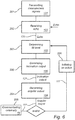
- Figure 6 schematically illustrates a method for a radar level gauge system, which system is attached to the hatch of the tank, comprising the steps of:
- the system or arrangement may also comprise a storage means, such as a memory 15, for holding at least one threshold value, and being connected to and accessible by the processor or a controller 17.
- the memory content could be adjustable or replaceable, in order to enable modification of the threshold value(s).
- the memory could e.g. be a conventional RAM, a flash-memory or the like.
- Preferably, a non-volatile memory is used.
- the system or arrangement may also comprise input means for inputting data for replacing or adjusting the threshold value in the memory 15.
- the data input means could be a data input interface 16 to be connected to an extern control unit or to a portable device such as a handheld computer.
- the data input means could comprise stationary input equipment, such as a keyboard, a touch screen or the like.
- the input means could also be adapted to enable authorization and/or authentication control of input data.
- authorization/authentication control could be executed and managed by the processor 11.
- the input means may request a password or similar authentication tokens in order to permit modification of the stored threshold data.
- system or arrangement may comprise a controller 17 adapted to receive the angular output 111, and to compare said angular output 111 to the threshold value(s), and to initiate an activity such as activate an alarm and/or discontinue the transmittance of the measuring signals, based on the result of said comparison.
- an alarm may be activated and/or the transmittance of the measuring signals may be discontinued.
- the threshold value(s) may also be chosen such that an alarm is activated and/or the transmittance of the measuring signals is discontinued when the hatch is opened.
- the threshold value(s) may also be chosen such that an alarm is activated when the hatch has been open longer than a predetermined time.
- the system or arrangement may further comprise a presenter 19 connected to said second processing circuitry 11 and being adapted to receive said angular output 111 and to generate a communication output communicating information about the angular difference to a receiver 200 of the communication output.
- a presenter 19 connected to said second processing circuitry 11 and being adapted to receive said angular output 111 and to generate a communication output communicating information about the angular difference to a receiver 200 of the communication output.
- information about the orientation of the hatch may be forwarded to a presenter to inform a receiver about the orientation of the hatch.
- the presenter may e.g. be a display, a loud speaker or a lamp, and the receiver may be a device or an operator [the lists are non-exhaustive].
- the information communicated via the presenter may e.g. be used to continuously monitoring the orientation of the hatch, and/or for aiding a person to find a correct orientation of the antenna beam.
- the information can be given as a deviation from a given axis or a plane, which may be given continuously and instantaneously to the operator so that the operator is informed when the hatch and/or the RLG has been given the correct orientation.
- the information about the orientation of the hatch may also be used for automatically, i.e. non-manually, give the hatch and/or the RLG a desired orientation e.g. by electronic control means.
- the values from the inclination output and/or angular output is received by a control device which adjusts the RLG and/or the hatch based on the result from the comparison of the angular output and the at least one threshold value.
- a control device which adjusts the RLG and/or the hatch based on the result from the comparison of the angular output and the at least one threshold value.
- this can be verified by checking the current inclination output and/or the current angular output.
- the inclinometer can be used by the processor in the RLG to automatically compensate for non-ideal installations of the antenna. In other words, when a level measurement has been generated based on the reflected signal, this value can be used to adjust the direction in which the antenaa is pointing.
Landscapes
- Physics & Mathematics (AREA)
- Engineering & Computer Science (AREA)
- Radar, Positioning & Navigation (AREA)
- Remote Sensing (AREA)
- General Physics & Mathematics (AREA)
- Electromagnetism (AREA)
- Computer Networks & Wireless Communication (AREA)
- Fluid Mechanics (AREA)
- Thermal Sciences (AREA)
- Measurement Of Levels Of Liquids Or Fluent Solid Materials (AREA)
- Radar Systems Or Details Thereof (AREA)
Claims (11)
- Radarfüllstandsanzeiger-System (RLG-System) (1) zum Montieren auf einer Luke (20) eines Tanks (5), umfassend:- ein Gehäuse (13), das ausgelegt ist, um an einer Luke eines Tanks angebracht zu sein, wobei das Gehäuse ausgelegt ist, um der Drehbewegung der Luke zu folgen, wenn es an ihr angebracht ist,- einen Träger (100), der im Inneren des Gehäuses angeordnet ist,- einen Sender, der im Inneren des Gehäuses angeordnet ist, wobei der Sender an dem Träger angebracht und ausgelegt ist, um Messsignale zumindest entlang einer ersten Achse (A) zum Messen des Abstands zu einer Fläche (2) in einem Tank zu senden,- einen Empfänger (102), der im Inneren des Gehäuses angeordnet und ausgelegt ist, um Echosignale zu empfangen, die dem Abstand zu der Fläche in dem Tank entsprechen, wenn die erste Achse parallel zu einer Normalen zu der Fläche ist,- eine erste Verarbeitungsschaltungsanordnung (103), die im Inneren des Gehäuses angeordnet ist, die ausgelegt ist, um Echosignale zu empfangen und um einen Füllstand des Tanks basierend auf dem Echosignal zu bestimmen,- ein Neigungssensor (120), der im Inneren des Gehäuses angeordnet und an dem Träger angebracht ist, wodurch der Sensor einer Drehbewegung der Luke folgt, wodurch der Sensor einer Drehbewegung der Luke folgt und ausgelegt ist, um eine Neigungsausgabe (121) zu erzeugen, die der Neigung des Sensors relativ zu der Normalen zu der Fläche entspricht,- eine zweite Verarbeitungsschaltungsanordnung (104), die im Inneren des Gehäuses angeordnet und ausgelegt ist, um die Neigungsausgabe zu empfangen und um, basierend auf der Neigungsausgabe, eine Winkelausgabe (111) zu erzeugen, wenn eine Winkeldifferenz zwischen der ersten Achse und der Normalen zu der Fläche vorliegt,ferner umfassend:- eine Präsentiereinrichtung (19), die ausgelegt ist, um die Winkelausgabe von der zweiten Verarbeitungsschaltungsanordnung zu empfangen und um eine Übermittlungsausgabe (141) zu erzeugen, die Informationen über die Winkeldifferenz von dem System nach außen übermittelt, und wobei die Übermittlungsausgabe Statusinformationen umfasst, wobei die Statusinformationen einen Teil umfassen, der den Wert einer gegebenen Eigenschaft des RLG-Systems angibt, wobei die gegebene Eigenschaft mindestens eines von ist von: dass die Luke offen ist, die Winkelgeschwindigkeit, mit der die Luke bewegt wurde, oder die Zeitdauer, in der die Luke geöffnet war,
und- einen Übermittlungsweg (105), der im Inneren des Gehäuses angeordnet ist, der die erste Verarbeitungsschaltungsanordnung und die zweite Verarbeitungsschaltungsanordnung elektrisch verbindet und ausgelegt ist, um die Winkelausgabe von der zweiten Verarbeitungsschaltungsanordnung zu empfangen und um die Winkelausgabe (111) an die erste Verarbeitungsschaltungsanordnung zu übermitteln, und wobei die erste Verarbeitungsschaltungsanordnung ausgelegt ist, um eine Aktion basierend auf der Winkelausgabe einzuleiten, wobei die Aktion mindestens eines ist von: automatisches Einstellen der Luke in die angemessene Position und
Zurücksetzen der Messung des Abstands zu einer Fläche in einem Tank, nachdem die Luke geöffnet wurde, bevor Messungen der Füllstände wieder aufgenommen werden. - Radarfüllstandsanzeiger-Anordnung nach Anspruch 1, wobei die Neigungsausgabe (121) auf einem Vektor basiert, der eine erste Anzahl von Elementen aufweist, und wobei die erste Anzahl von Elementen 1, 2 oder 3 ist.
- Radarfüllstandsanzeiger-Anordnung nach einem der vorhergehenden Ansprüche, wobei das System die Präsentiereinrichtung (19) umfasst und die zweite Verarbeitungsschaltungsanordnung ferner ausgelegt ist, um die Neigungsausgabe mit mindestens einem vorbestimmten Schwellenwert zu vergleichen und um die Winkelausgabe basierend auf dem Ergebnis von dem Vergleich der Neigungsausgabe und des mindestens einen Schwellenwerts zu erzeugen, und
wobei die Präsentiereinrichtung ferner ausgelegt ist, um einen Alarm (141) basierend auf der Winkelausgabe abzugeben. - Radarfüllstandsanzeiger-Anordnung nach einem der vorhergehenden Ansprüche, wobei die Präsentiereinrichtung (19) eine Anzeige und/oder einen Lautsprecher und/oder einen Sender elektromagnetischer Strahlung umfasst.
- Radarfüllstandsanzeiger-Anordnung nach Anspruch 3, ferner umfassend ein Dateneingabemittel (16) zum Eingeben von Daten zum Einstellen des Schwellenwerts.
- Radarfüllstandsanzeiger-Anordnung nach einem der vorhergehenden Ansprüche, wobei das System einen Übermittlungsweg (105) umfasst und die erste Verarbeitungsschaltungsanordnung ausgelegt ist, um eine Aktion basierend auf der Winkelausgabe einzuleiten, wobei die Aktion mindestens eines ist von: Abbrechen des Sendens der Messsignale, Zurücksetzen der Messung des Abstands zu einer Fläche in einem Tank und Einstellen des Werts des bestimmten Füllstands in dem Tank.
- Radarfüllstandsanzeiger-Anordnung nach einem der vorhergehenden Ansprüche, wobei die erste Verarbeitungsschaltungsanordnung (103) und die zweite Verarbeitungsschaltungsanordnung (104) in einer gemeinsamen Schaltung integriert sind.
- Radarfüllstandsanzeiger-Anordnung nach einem der vorhergehenden Ansprüche, ferner umfassend eine Wellenleiterstruktur (14) zum Leiten der Messsignale in dem Tank.
- Verfahren für ein Radarfüllstandanzeiger-System (1), wobei das System an der Luke (20) des Tanks (5) angebracht ist und einer Drehbewegung der Luke folgt, umfassend:- Senden von Messsignalen (201) zumindest entlang einer ersten Achse (A) zum Messen des Abstands zu einer Fläche (2) in einem Tank (5), wobei die erste Achse einer Drehbewegung der Luke folgt,- Empfangen (202) von Echosignalen, die dem Abstand zu der Fläche in dem Tank entsprechen, wenn die erste Achse parallel zu einer Normalen zu der Fläche ist,- Bestimmen (203) eines Füllstands des Tanks basierend auf dem empfangenen Echosignal,- Erzeugen (220) einer Neigungsausgabe, die der Ausrichtung der ersten Achse entspricht,- Erzeugen (204), basierend auf der Neigungsausgabe, einer Winkelausgabe, wenn eine Winkeldifferenz zwischen der ersten Achse und der Normalen zu der Fläche vorliegt,ferner umfassend:- Übermitteln von Informationen (205) über die Winkeldifferenz von dem System nach außen, wobei die Informationen mindestens eines sind von: dass die Luke offen ist, die Winkelgeschwindigkeit, mit der die Luke bewegt wurde, und die Zeitdauer, in der die Luke geöffnet war;
und- Einleiten (206) einer Aktion basierend auf der Winkelausgabe, wobei die Aktion den Schritt zum Bestimmen eines Füllstands des Tanks beeinflusst, wobei die Aktion mindestens eines ist von: automatisches Einstellen der Luke in die angemessene Position und Zurücksetzen der Messung des Abstands zu einer Fläche in einem Tank, nachdem die Luke geöffnet wurde, bevor Messungen der Füllstände wieder aufgenommen werden. - Verfahren nach Anspruch 9, umfassend Einleiten (206) einer Aktion basierend auf der Winkelausgabe, und wobei die Aktion ein Einstellen des bestimmten Füllstands des Tanks basierend auf der Winkelausgabe und/oder ein Abbrechen des Sendens von Messsignalen und/oder ein Zurücksetzen der Messung des Abstands zu der Fläche in dem Tank umfasst.
- Verfahren nach Anspruch 9 oder 10, umfassend Übermitteln von Informationen (205) über die Winkeldifferenz von dem System nach außen, ferner umfassend Vergleichen der Neigungsausgabe (111) mit mindestens einem vorbestimmten Schwellenwert, um (204) die Winkelausgabe basierend auf dem Ergebnis von dem Vergleich der Neigungsausgabe und des mindestens einen Schwellenwerts zu erzeugen, und
Abgeben (205) eines Alarms basierend auf der Winkelausgabe.
Applications Claiming Priority (1)
| Application Number | Priority Date | Filing Date | Title |
|---|---|---|---|
| US14/319,340 US9658096B2 (en) | 2014-06-30 | 2014-06-30 | Radar level gauge inclination system |
Publications (2)
| Publication Number | Publication Date |
|---|---|
| EP2963397A1 EP2963397A1 (de) | 2016-01-06 |
| EP2963397B1 true EP2963397B1 (de) | 2021-08-04 |
Family
ID=52869693
Family Applications (1)
| Application Number | Title | Priority Date | Filing Date |
|---|---|---|---|
| EP15174254.1A Active EP2963397B1 (de) | 2014-06-30 | 2015-06-29 | Radarfüllstandmessgerät-neigungssystem |
Country Status (4)
| Country | Link |
|---|---|
| US (2) | US9658096B2 (de) |
| EP (1) | EP2963397B1 (de) |
| KR (1) | KR20160002390A (de) |
| CN (2) | CN204286543U (de) |
Families Citing this family (21)
| Publication number | Priority date | Publication date | Assignee | Title |
|---|---|---|---|---|
| US9841307B2 (en) * | 2014-09-30 | 2017-12-12 | Rosemount Inc. | Multivariable guided wave radar probe |
| WO2017120675A1 (en) * | 2016-01-13 | 2017-07-20 | Transrail Innovation Inc. | Device and method for measuring commodity volume in a rail tank car |
| CN109196314B (zh) * | 2016-02-09 | 2021-11-19 | Vega美洲公司 | 用于测深管中的液位测量和内容物纯度测量的装置和方法 |
| US10397667B2 (en) * | 2017-09-28 | 2019-08-27 | Intel IP Corporation | Sensor position optimization by active flexible device housing |
| EP3540384B1 (de) * | 2018-03-14 | 2021-07-21 | VEGA Grieshaber KG | Radarfüllstandmessgerät und verfahren zum betreiben eines radarfüllstandmessgerätes |
| EP3605031B1 (de) * | 2018-08-02 | 2021-04-07 | VEGA Grieshaber KG | Radarsensor zur füllstand- oder grenzstandmessung |
| GB2578607A (en) * | 2018-10-31 | 2020-05-20 | Hwm Water Ltd | Level sensing apparatus |
| US11187626B2 (en) * | 2018-11-20 | 2021-11-30 | Watgrid, S.A. | Fermentation monitoring system |
| DE102019202137A1 (de) * | 2019-02-18 | 2020-08-20 | Fraunhofer-Gesellschaft zur Förderung der angewandten Forschung e.V. | Winkelkorrigierte füllstandsermittlung |
| WO2021014686A1 (ja) * | 2019-07-24 | 2021-01-28 | ソニー株式会社 | レーダー装置、処理装置、算出方法、及び算出プログラム |
| CN110398275A (zh) * | 2019-08-06 | 2019-11-01 | 陕西诺盈自动化仪表有限公司 | 一种通过雷达液位计判断煤气管道内积水的装置 |
| KR102243227B1 (ko) * | 2019-08-07 | 2021-04-21 | 박원일 | 실시간으로 모니터링되는 저장 탱크 적재물 부피 측정장치 |
| CN110646064A (zh) * | 2019-09-24 | 2020-01-03 | 红云红河烟草(集团)有限责任公司 | 一种基于k波雷达物位成像技术的生产线阻料诊断的方法 |
| DE102020206108A1 (de) * | 2020-05-14 | 2021-11-18 | Vega Grieshaber Kg | Füllstandmessanordnung zum Bestimmen eines Füllstands oder Volumens eines Füllguts in einem mobilen Behälter |
| US12111200B2 (en) * | 2020-12-15 | 2024-10-08 | Hadronex, Inc. | Phased array radar for fluid sensing |
| CN112945351B (zh) * | 2021-03-12 | 2022-01-04 | 中灌顺鑫华霖科技发展有限公司 | 一种微波水位计及水位测定方法 |
| CN112882024B (zh) * | 2021-03-25 | 2025-02-18 | 浙江大华技术股份有限公司 | 雷达检测方法和装置、存储介质及电子装置 |
| EP4361575A1 (de) * | 2022-10-28 | 2024-05-01 | Biotage AB | Verfahren zur überwachung des flüssigkeitsgehalts |
| EP4361579A1 (de) * | 2022-10-28 | 2024-05-01 | Biotage AB | Sensoranordnung |
| CN116734952B (zh) * | 2023-04-28 | 2023-12-15 | 河北华创测控技术有限公司 | 一种高精度雷达物位测控系统 |
| CN118706223A (zh) * | 2024-06-02 | 2024-09-27 | 珠海艾尔仪表有限公司 | 雷达物位计 |
Citations (1)
| Publication number | Priority date | Publication date | Assignee | Title |
|---|---|---|---|---|
| DE10242500A1 (de) * | 2002-09-12 | 2004-03-18 | Endress + Hauser Gmbh + Co. Kg | Ausrichtvorrichtung für ein Meßgerät |
Family Cites Families (25)
| Publication number | Priority date | Publication date | Assignee | Title |
|---|---|---|---|---|
| US3675227A (en) | 1970-04-01 | 1972-07-04 | Nissan Motor | Liquid-level drop alarming system |
| US3974699A (en) | 1973-08-28 | 1976-08-17 | Systron Donner Corporation | Angular position sensing and control system, apparatus and method |
| US5072615A (en) | 1990-12-17 | 1991-12-17 | Ford Motor Company | Apparatus and method for gauging the amount of fuel in a vehicle fuel tank subject to tilt |
| GB9102195D0 (en) | 1991-02-01 | 1991-03-20 | Smiths Industries Plc | Liquid quantity gauging |
| US5386736A (en) | 1992-10-27 | 1995-02-07 | Simmonds Precision Products, Inc. | Fluid tank with integral fluid quantity gauging |
| US6859166B2 (en) * | 2002-12-04 | 2005-02-22 | Saab Marine Electronics Ab | Antenna device for radar-based level gauging |
| KR20050070356A (ko) | 2003-12-30 | 2005-07-07 | 주식회사 현대오토넷 | 차량의 유량 측정 장치 |
| US20060004413A1 (en) * | 2004-06-30 | 2006-01-05 | Peng-Sheng Chen | Method and system for the prediction of cardiac arrhythmias |
| DE102004041857A1 (de) | 2004-08-27 | 2006-03-02 | Endress + Hauser Gmbh + Co. Kg | Verfahren und Vorrichtung zum Ausrichten eines Messgerätes |
| US7319401B2 (en) * | 2004-08-27 | 2008-01-15 | Rosemount Tank Radar Ab | Radar level gauge system with variable alarm limits |
| US7173436B2 (en) * | 2004-11-24 | 2007-02-06 | Saab Rosemount Tank Radar Ag | Antenna device for level gauging |
| DE102005036846B4 (de) * | 2005-08-04 | 2016-11-24 | Vega Grieshaber Kg | Vorrichtung zum Messen eines Füllstands |
| DE102006030965A1 (de) * | 2006-07-03 | 2008-01-10 | Endress + Hauser Gmbh + Co. Kg | Vorrichtung zur Ermittlung und/oder Überwachung des Füllstandes eines Mediums |
| US7835880B2 (en) | 2007-09-29 | 2010-11-16 | Imu Solutions, Inc. | Methods for improving accuracy of measurement and calibration of accelerometer parameters |
| BRPI0721994B1 (pt) * | 2007-10-16 | 2018-10-09 | Asis Akaryakit Servis Istasyon Sistemleri Ve Insaat Sanayi Ve Ticaret Ltd Sirketi | método e equipamento para formar o quadro de calibração para os tanques de combustível subterrâneos |
| JP2009139212A (ja) | 2007-12-06 | 2009-06-25 | Ricoh Elemex Corp | 超音波式液面計 |
| EP2124018A1 (de) | 2008-05-21 | 2009-11-25 | VEGA Grieshaber KG | Füllstandsmessung in mobilen Behältern oder Transportsilos |
| DE102010064394A1 (de) * | 2010-12-30 | 2012-07-05 | Endress + Hauser Gmbh + Co. Kg | Verfahren und Vorrichtung zum Ausrichten eines Messgerätes |
| US20120281096A1 (en) * | 2011-05-02 | 2012-11-08 | Honeywell-Enraf B.V. | Storage tank inspection system and method |
| US8248467B1 (en) * | 2011-07-26 | 2012-08-21 | ByteLight, Inc. | Light positioning system using digital pulse recognition |
| US9377340B2 (en) * | 2011-11-11 | 2016-06-28 | Rosemount Tank Radar Ab | Monitoring of floating roof tank |
| US8726728B2 (en) * | 2012-03-13 | 2014-05-20 | Rosemount Tank Radar Ab | Level gauge system with wettable propagation device |
| US9046406B2 (en) * | 2012-04-11 | 2015-06-02 | Honeywell International Inc. | Advanced antenna protection for radars in level gauging and other applications |
| EP2803951B1 (de) * | 2013-05-17 | 2020-02-26 | VEGA Grieshaber KG | Topologiebestimmung für Schüttgüter |
| US10374284B2 (en) * | 2014-10-22 | 2019-08-06 | Vega Grieshaber Kg | Topology determination of a filling material surface with uniform line scanning |
-
2014
- 2014-06-30 US US14/319,340 patent/US9658096B2/en active Active
- 2014-09-25 CN CN201420555988.3U patent/CN204286543U/zh not_active Expired - Lifetime
- 2014-09-25 CN CN201410497861.5A patent/CN105300476B/zh active Active
-
2015
- 2015-06-29 EP EP15174254.1A patent/EP2963397B1/de active Active
- 2015-06-29 KR KR1020150092001A patent/KR20160002390A/ko not_active Ceased
-
2017
- 2017-05-22 US US15/601,185 patent/US20170356786A1/en not_active Abandoned
Patent Citations (1)
| Publication number | Priority date | Publication date | Assignee | Title |
|---|---|---|---|---|
| DE10242500A1 (de) * | 2002-09-12 | 2004-03-18 | Endress + Hauser Gmbh + Co. Kg | Ausrichtvorrichtung für ein Meßgerät |
Also Published As
| Publication number | Publication date |
|---|---|
| CN204286543U (zh) | 2015-04-22 |
| US20150377681A1 (en) | 2015-12-31 |
| EP2963397A1 (de) | 2016-01-06 |
| US9658096B2 (en) | 2017-05-23 |
| CN105300476B (zh) | 2020-11-27 |
| KR20160002390A (ko) | 2016-01-07 |
| US20170356786A1 (en) | 2017-12-14 |
| CN105300476A (zh) | 2016-02-03 |
Similar Documents
| Publication | Publication Date | Title |
|---|---|---|
| EP2963397B1 (de) | Radarfüllstandmessgerät-neigungssystem | |
| CN100483083C (zh) | 具有可变告警极限的雷达液位计量系统 | |
| US11340106B2 (en) | Fill-level measuring device | |
| US20210080310A1 (en) | Floating roof monitoring | |
| US9989401B2 (en) | Method and apparatus for orienting a measuring device | |
| US6295018B1 (en) | Low power radar level instrument with enhanced diagnostics | |
| US6672155B2 (en) | Apparatus for determining the filling level of a filling material in a container | |
| US9304029B2 (en) | Level gauging system for long narrow nozzles | |
| US20170219409A1 (en) | Radar-based fill level measurement device having a security device | |
| US12072223B2 (en) | Through the wall tank level measurement with telemetry and millimeter wave radar | |
| US10422682B2 (en) | Radar level gauge comprising a safety device | |
| US7082828B1 (en) | Laser measurement of liquid level in a holder | |
| US9684061B2 (en) | Method for determining a fill level of a medium and device for determining a fill level of a medium | |
| US9024807B2 (en) | Verification of a level gauge system | |
| CN112284489A (zh) | 雷达传感器、可更换的雷达传感器装置、现场设备和容器 | |
| US20230130890A1 (en) | Sensor assembly with alignment device | |
| US12111200B2 (en) | Phased array radar for fluid sensing | |
| US10295392B1 (en) | Removable portable wireless fluid sensor system | |
| US20250027804A1 (en) | Phased array radar for fluid sensing | |
| US20240011817A1 (en) | Field device and method for replacing a sensor in a field device | |
| Little | Going the Distance: Solids Level Measurement with Radar |
Legal Events
| Date | Code | Title | Description |
|---|---|---|---|
| PUAI | Public reference made under article 153(3) epc to a published international application that has entered the european phase |
Free format text: ORIGINAL CODE: 0009012 |
|
| AK | Designated contracting states |
Kind code of ref document: A1 Designated state(s): AL AT BE BG CH CY CZ DE DK EE ES FI FR GB GR HR HU IE IS IT LI LT LU LV MC MK MT NL NO PL PT RO RS SE SI SK SM TR |
|
| AX | Request for extension of the european patent |
Extension state: BA ME |
|
| 17P | Request for examination filed |
Effective date: 20160621 |
|
| RBV | Designated contracting states (corrected) |
Designated state(s): AL AT BE BG CH CY CZ DE DK EE ES FI FR GB GR HR HU IE IS IT LI LT LU LV MC MK MT NL NO PL PT RO RS SE SI SK SM TR |
|
| RAP1 | Party data changed (applicant data changed or rights of an application transferred) |
Owner name: ROSEMOUNT TANK RADAR AB |
|
| STAA | Information on the status of an ep patent application or granted ep patent |
Free format text: STATUS: EXAMINATION IS IN PROGRESS |
|
| 17Q | First examination report despatched |
Effective date: 20180502 |
|
| RIC1 | Information provided on ipc code assigned before grant |
Ipc: G01S 7/02 20060101ALI20201027BHEP Ipc: G01F 25/00 20060101ALI20201027BHEP Ipc: G01F 23/284 20060101AFI20201027BHEP Ipc: G01S 7/40 20060101ALI20201027BHEP Ipc: G01S 13/88 20060101ALI20201027BHEP |
|
| GRAP | Despatch of communication of intention to grant a patent |
Free format text: ORIGINAL CODE: EPIDOSNIGR1 |
|
| STAA | Information on the status of an ep patent application or granted ep patent |
Free format text: STATUS: GRANT OF PATENT IS INTENDED |
|
| INTG | Intention to grant announced |
Effective date: 20210210 |
|
| GRAS | Grant fee paid |
Free format text: ORIGINAL CODE: EPIDOSNIGR3 |
|
| GRAA | (expected) grant |
Free format text: ORIGINAL CODE: 0009210 |
|
| STAA | Information on the status of an ep patent application or granted ep patent |
Free format text: STATUS: THE PATENT HAS BEEN GRANTED |
|
| AK | Designated contracting states |
Kind code of ref document: B1 Designated state(s): AL AT BE BG CH CY CZ DE DK EE ES FI FR GB GR HR HU IE IS IT LI LT LU LV MC MK MT NL NO PL PT RO RS SE SI SK SM TR |
|
| REG | Reference to a national code |
Ref country code: GB Ref legal event code: FG4D |
|
| REG | Reference to a national code |
Ref country code: AT Ref legal event code: REF Ref document number: 1417421 Country of ref document: AT Kind code of ref document: T Effective date: 20210815 |
|
| REG | Reference to a national code |
Ref country code: CH Ref legal event code: EP |
|
| REG | Reference to a national code |
Ref country code: DE Ref legal event code: R096 Ref document number: 602015071879 Country of ref document: DE |
|
| REG | Reference to a national code |
Ref country code: IE Ref legal event code: FG4D |
|
| REG | Reference to a national code |
Ref country code: LT Ref legal event code: MG9D |
|
| REG | Reference to a national code |
Ref country code: NL Ref legal event code: MP Effective date: 20210804 |
|
| REG | Reference to a national code |
Ref country code: AT Ref legal event code: MK05 Ref document number: 1417421 Country of ref document: AT Kind code of ref document: T Effective date: 20210804 |
|
| PG25 | Lapsed in a contracting state [announced via postgrant information from national office to epo] |
Ref country code: AT Free format text: LAPSE BECAUSE OF FAILURE TO SUBMIT A TRANSLATION OF THE DESCRIPTION OR TO PAY THE FEE WITHIN THE PRESCRIBED TIME-LIMIT Effective date: 20210804 Ref country code: BG Free format text: LAPSE BECAUSE OF FAILURE TO SUBMIT A TRANSLATION OF THE DESCRIPTION OR TO PAY THE FEE WITHIN THE PRESCRIBED TIME-LIMIT Effective date: 20211104 Ref country code: LT Free format text: LAPSE BECAUSE OF FAILURE TO SUBMIT A TRANSLATION OF THE DESCRIPTION OR TO PAY THE FEE WITHIN THE PRESCRIBED TIME-LIMIT Effective date: 20210804 Ref country code: ES Free format text: LAPSE BECAUSE OF FAILURE TO SUBMIT A TRANSLATION OF THE DESCRIPTION OR TO PAY THE FEE WITHIN THE PRESCRIBED TIME-LIMIT Effective date: 20210804 Ref country code: FI Free format text: LAPSE BECAUSE OF FAILURE TO SUBMIT A TRANSLATION OF THE DESCRIPTION OR TO PAY THE FEE WITHIN THE PRESCRIBED TIME-LIMIT Effective date: 20210804 Ref country code: PT Free format text: LAPSE BECAUSE OF FAILURE TO SUBMIT A TRANSLATION OF THE DESCRIPTION OR TO PAY THE FEE WITHIN THE PRESCRIBED TIME-LIMIT Effective date: 20211206 Ref country code: NO Free format text: LAPSE BECAUSE OF FAILURE TO SUBMIT A TRANSLATION OF THE DESCRIPTION OR TO PAY THE FEE WITHIN THE PRESCRIBED TIME-LIMIT Effective date: 20211104 Ref country code: HR Free format text: LAPSE BECAUSE OF FAILURE TO SUBMIT A TRANSLATION OF THE DESCRIPTION OR TO PAY THE FEE WITHIN THE PRESCRIBED TIME-LIMIT Effective date: 20210804 Ref country code: RS Free format text: LAPSE BECAUSE OF FAILURE TO SUBMIT A TRANSLATION OF THE DESCRIPTION OR TO PAY THE FEE WITHIN THE PRESCRIBED TIME-LIMIT Effective date: 20210804 Ref country code: SE Free format text: LAPSE BECAUSE OF FAILURE TO SUBMIT A TRANSLATION OF THE DESCRIPTION OR TO PAY THE FEE WITHIN THE PRESCRIBED TIME-LIMIT Effective date: 20210804 |
|
| PG25 | Lapsed in a contracting state [announced via postgrant information from national office to epo] |
Ref country code: PL Free format text: LAPSE BECAUSE OF FAILURE TO SUBMIT A TRANSLATION OF THE DESCRIPTION OR TO PAY THE FEE WITHIN THE PRESCRIBED TIME-LIMIT Effective date: 20210804 Ref country code: LV Free format text: LAPSE BECAUSE OF FAILURE TO SUBMIT A TRANSLATION OF THE DESCRIPTION OR TO PAY THE FEE WITHIN THE PRESCRIBED TIME-LIMIT Effective date: 20210804 Ref country code: GR Free format text: LAPSE BECAUSE OF FAILURE TO SUBMIT A TRANSLATION OF THE DESCRIPTION OR TO PAY THE FEE WITHIN THE PRESCRIBED TIME-LIMIT Effective date: 20211105 |
|
| PG25 | Lapsed in a contracting state [announced via postgrant information from national office to epo] |
Ref country code: NL Free format text: LAPSE BECAUSE OF FAILURE TO SUBMIT A TRANSLATION OF THE DESCRIPTION OR TO PAY THE FEE WITHIN THE PRESCRIBED TIME-LIMIT Effective date: 20210804 |
|
| PG25 | Lapsed in a contracting state [announced via postgrant information from national office to epo] |
Ref country code: DK Free format text: LAPSE BECAUSE OF FAILURE TO SUBMIT A TRANSLATION OF THE DESCRIPTION OR TO PAY THE FEE WITHIN THE PRESCRIBED TIME-LIMIT Effective date: 20210804 |
|
| REG | Reference to a national code |
Ref country code: DE Ref legal event code: R097 Ref document number: 602015071879 Country of ref document: DE |
|
| PG25 | Lapsed in a contracting state [announced via postgrant information from national office to epo] |
Ref country code: SM Free format text: LAPSE BECAUSE OF FAILURE TO SUBMIT A TRANSLATION OF THE DESCRIPTION OR TO PAY THE FEE WITHIN THE PRESCRIBED TIME-LIMIT Effective date: 20210804 Ref country code: SK Free format text: LAPSE BECAUSE OF FAILURE TO SUBMIT A TRANSLATION OF THE DESCRIPTION OR TO PAY THE FEE WITHIN THE PRESCRIBED TIME-LIMIT Effective date: 20210804 Ref country code: RO Free format text: LAPSE BECAUSE OF FAILURE TO SUBMIT A TRANSLATION OF THE DESCRIPTION OR TO PAY THE FEE WITHIN THE PRESCRIBED TIME-LIMIT Effective date: 20210804 Ref country code: EE Free format text: LAPSE BECAUSE OF FAILURE TO SUBMIT A TRANSLATION OF THE DESCRIPTION OR TO PAY THE FEE WITHIN THE PRESCRIBED TIME-LIMIT Effective date: 20210804 Ref country code: CZ Free format text: LAPSE BECAUSE OF FAILURE TO SUBMIT A TRANSLATION OF THE DESCRIPTION OR TO PAY THE FEE WITHIN THE PRESCRIBED TIME-LIMIT Effective date: 20210804 Ref country code: AL Free format text: LAPSE BECAUSE OF FAILURE TO SUBMIT A TRANSLATION OF THE DESCRIPTION OR TO PAY THE FEE WITHIN THE PRESCRIBED TIME-LIMIT Effective date: 20210804 |
|
| PLBE | No opposition filed within time limit |
Free format text: ORIGINAL CODE: 0009261 |
|
| STAA | Information on the status of an ep patent application or granted ep patent |
Free format text: STATUS: NO OPPOSITION FILED WITHIN TIME LIMIT |
|
| 26N | No opposition filed |
Effective date: 20220506 |
|
| PG25 | Lapsed in a contracting state [announced via postgrant information from national office to epo] |
Ref country code: IT Free format text: LAPSE BECAUSE OF FAILURE TO SUBMIT A TRANSLATION OF THE DESCRIPTION OR TO PAY THE FEE WITHIN THE PRESCRIBED TIME-LIMIT Effective date: 20210804 |
|
| PG25 | Lapsed in a contracting state [announced via postgrant information from national office to epo] |
Ref country code: SI Free format text: LAPSE BECAUSE OF FAILURE TO SUBMIT A TRANSLATION OF THE DESCRIPTION OR TO PAY THE FEE WITHIN THE PRESCRIBED TIME-LIMIT Effective date: 20210804 |
|
| PG25 | Lapsed in a contracting state [announced via postgrant information from national office to epo] |
Ref country code: MC Free format text: LAPSE BECAUSE OF FAILURE TO SUBMIT A TRANSLATION OF THE DESCRIPTION OR TO PAY THE FEE WITHIN THE PRESCRIBED TIME-LIMIT Effective date: 20210804 |
|
| REG | Reference to a national code |
Ref country code: BE Ref legal event code: MM Effective date: 20220630 |
|
| GBPC | Gb: european patent ceased through non-payment of renewal fee |
Effective date: 20220629 |
|
| PG25 | Lapsed in a contracting state [announced via postgrant information from national office to epo] |
Ref country code: LU Free format text: LAPSE BECAUSE OF NON-PAYMENT OF DUE FEES Effective date: 20220629 Ref country code: IE Free format text: LAPSE BECAUSE OF NON-PAYMENT OF DUE FEES Effective date: 20220629 Ref country code: FR Free format text: LAPSE BECAUSE OF NON-PAYMENT OF DUE FEES Effective date: 20220630 |
|
| PG25 | Lapsed in a contracting state [announced via postgrant information from national office to epo] |
Ref country code: GB Free format text: LAPSE BECAUSE OF NON-PAYMENT OF DUE FEES Effective date: 20220629 Ref country code: BE Free format text: LAPSE BECAUSE OF NON-PAYMENT OF DUE FEES Effective date: 20220630 |
|
| PG25 | Lapsed in a contracting state [announced via postgrant information from national office to epo] |
Ref country code: HU Free format text: LAPSE BECAUSE OF FAILURE TO SUBMIT A TRANSLATION OF THE DESCRIPTION OR TO PAY THE FEE WITHIN THE PRESCRIBED TIME-LIMIT; INVALID AB INITIO Effective date: 20150629 |
|
| PG25 | Lapsed in a contracting state [announced via postgrant information from national office to epo] |
Ref country code: MK Free format text: LAPSE BECAUSE OF FAILURE TO SUBMIT A TRANSLATION OF THE DESCRIPTION OR TO PAY THE FEE WITHIN THE PRESCRIBED TIME-LIMIT Effective date: 20210804 Ref country code: CY Free format text: LAPSE BECAUSE OF FAILURE TO SUBMIT A TRANSLATION OF THE DESCRIPTION OR TO PAY THE FEE WITHIN THE PRESCRIBED TIME-LIMIT Effective date: 20210804 |
|
| PG25 | Lapsed in a contracting state [announced via postgrant information from national office to epo] |
Ref country code: MT Free format text: LAPSE BECAUSE OF FAILURE TO SUBMIT A TRANSLATION OF THE DESCRIPTION OR TO PAY THE FEE WITHIN THE PRESCRIBED TIME-LIMIT Effective date: 20210804 |
|
| PGFP | Annual fee paid to national office [announced via postgrant information from national office to epo] |
Ref country code: CH Payment date: 20240701 Year of fee payment: 10 |
|
| PGFP | Annual fee paid to national office [announced via postgrant information from national office to epo] |
Ref country code: DE Payment date: 20250520 Year of fee payment: 11 |
|
| PG25 | Lapsed in a contracting state [announced via postgrant information from national office to epo] |
Ref country code: TR Free format text: LAPSE BECAUSE OF FAILURE TO SUBMIT A TRANSLATION OF THE DESCRIPTION OR TO PAY THE FEE WITHIN THE PRESCRIBED TIME-LIMIT Effective date: 20210804 |
|
| REG | Reference to a national code |
Ref country code: CH Ref legal event code: H13 Free format text: ST27 STATUS EVENT CODE: U-0-0-H10-H13 (AS PROVIDED BY THE NATIONAL OFFICE) Effective date: 20260127 |