EP2963340B1 - Träger für eine Linsenanordnung einer Beleuchtungsvorrichtung - Google Patents
Träger für eine Linsenanordnung einer Beleuchtungsvorrichtung Download PDFInfo
- Publication number
- EP2963340B1 EP2963340B1 EP14175893.8A EP14175893A EP2963340B1 EP 2963340 B1 EP2963340 B1 EP 2963340B1 EP 14175893 A EP14175893 A EP 14175893A EP 2963340 B1 EP2963340 B1 EP 2963340B1
- Authority
- EP
- European Patent Office
- Prior art keywords
- wall
- support
- lateral wall
- mounting
- carrier
- Prior art date
- Legal status (The legal status is an assumption and is not a legal conclusion. Google has not performed a legal analysis and makes no representation as to the accuracy of the status listed.)
- Not-in-force
Links
- 239000011796 hollow space material Substances 0.000 claims description 9
- XAGFODPZIPBFFR-UHFFFAOYSA-N aluminium Chemical compound [Al] XAGFODPZIPBFFR-UHFFFAOYSA-N 0.000 claims description 8
- 229910052782 aluminium Inorganic materials 0.000 claims description 8
- 239000000463 material Substances 0.000 claims description 8
- 238000004381 surface treatment Methods 0.000 claims description 6
- 238000013461 design Methods 0.000 claims description 3
- 238000005192 partition Methods 0.000 description 24
- 230000008901 benefit Effects 0.000 description 13
- 230000017525 heat dissipation Effects 0.000 description 11
- 238000000034 method Methods 0.000 description 4
- 230000000149 penetrating effect Effects 0.000 description 4
- 230000008569 process Effects 0.000 description 4
- 239000012080 ambient air Substances 0.000 description 3
- 238000005520 cutting process Methods 0.000 description 3
- 230000007613 environmental effect Effects 0.000 description 3
- 230000001681 protective effect Effects 0.000 description 3
- 230000005855 radiation Effects 0.000 description 3
- 238000013022 venting Methods 0.000 description 3
- XEEYBQQBJWHFJM-UHFFFAOYSA-N Iron Chemical compound [Fe] XEEYBQQBJWHFJM-UHFFFAOYSA-N 0.000 description 2
- 229910045601 alloy Inorganic materials 0.000 description 2
- 239000000956 alloy Substances 0.000 description 2
- 230000000712 assembly Effects 0.000 description 2
- 238000000429 assembly Methods 0.000 description 2
- 239000000969 carrier Substances 0.000 description 2
- 230000008859 change Effects 0.000 description 2
- 239000011248 coating agent Substances 0.000 description 2
- 238000000576 coating method Methods 0.000 description 2
- 230000000295 complement effect Effects 0.000 description 2
- 238000001816 cooling Methods 0.000 description 2
- 238000005260 corrosion Methods 0.000 description 2
- 230000007797 corrosion Effects 0.000 description 2
- 239000011159 matrix material Substances 0.000 description 2
- 239000002245 particle Substances 0.000 description 2
- 229910000838 Al alloy Inorganic materials 0.000 description 1
- VYZAMTAEIAYCRO-UHFFFAOYSA-N Chromium Chemical compound [Cr] VYZAMTAEIAYCRO-UHFFFAOYSA-N 0.000 description 1
- RYGMFSIKBFXOCR-UHFFFAOYSA-N Copper Chemical compound [Cu] RYGMFSIKBFXOCR-UHFFFAOYSA-N 0.000 description 1
- 240000006829 Ficus sundaica Species 0.000 description 1
- FYYHWMGAXLPEAU-UHFFFAOYSA-N Magnesium Chemical compound [Mg] FYYHWMGAXLPEAU-UHFFFAOYSA-N 0.000 description 1
- XUIMIQQOPSSXEZ-UHFFFAOYSA-N Silicon Chemical compound [Si] XUIMIQQOPSSXEZ-UHFFFAOYSA-N 0.000 description 1
- 229910000831 Steel Inorganic materials 0.000 description 1
- RTAQQCXQSZGOHL-UHFFFAOYSA-N Titanium Chemical compound [Ti] RTAQQCXQSZGOHL-UHFFFAOYSA-N 0.000 description 1
- HCHKCACWOHOZIP-UHFFFAOYSA-N Zinc Chemical compound [Zn] HCHKCACWOHOZIP-UHFFFAOYSA-N 0.000 description 1
- 238000005299 abrasion Methods 0.000 description 1
- 230000001154 acute effect Effects 0.000 description 1
- 238000007792 addition Methods 0.000 description 1
- 239000000853 adhesive Substances 0.000 description 1
- 238000004026 adhesive bonding Methods 0.000 description 1
- 230000001070 adhesive effect Effects 0.000 description 1
- 239000003570 air Substances 0.000 description 1
- 238000002048 anodisation reaction Methods 0.000 description 1
- 238000007743 anodising Methods 0.000 description 1
- 230000015572 biosynthetic process Effects 0.000 description 1
- 229910052804 chromium Inorganic materials 0.000 description 1
- 239000011651 chromium Substances 0.000 description 1
- 238000009833 condensation Methods 0.000 description 1
- 230000005494 condensation Effects 0.000 description 1
- 239000000470 constituent Substances 0.000 description 1
- 229910052802 copper Inorganic materials 0.000 description 1
- 239000010949 copper Substances 0.000 description 1
- 238000011161 development Methods 0.000 description 1
- 230000018109 developmental process Effects 0.000 description 1
- 239000000428 dust Substances 0.000 description 1
- 238000001125 extrusion Methods 0.000 description 1
- 230000006872 improvement Effects 0.000 description 1
- 229910052742 iron Inorganic materials 0.000 description 1
- 238000002955 isolation Methods 0.000 description 1
- 239000004922 lacquer Substances 0.000 description 1
- 229910052749 magnesium Inorganic materials 0.000 description 1
- 239000011777 magnesium Substances 0.000 description 1
- WPBNNNQJVZRUHP-UHFFFAOYSA-L manganese(2+);methyl n-[[2-(methoxycarbonylcarbamothioylamino)phenyl]carbamothioyl]carbamate;n-[2-(sulfidocarbothioylamino)ethyl]carbamodithioate Chemical compound [Mn+2].[S-]C(=S)NCCNC([S-])=S.COC(=O)NC(=S)NC1=CC=CC=C1NC(=S)NC(=O)OC WPBNNNQJVZRUHP-UHFFFAOYSA-L 0.000 description 1
- 238000004519 manufacturing process Methods 0.000 description 1
- 239000004033 plastic Substances 0.000 description 1
- 238000003825 pressing Methods 0.000 description 1
- 239000011241 protective layer Substances 0.000 description 1
- 150000003839 salts Chemical class 0.000 description 1
- 239000000565 sealant Substances 0.000 description 1
- 229910052710 silicon Inorganic materials 0.000 description 1
- 239000010703 silicon Substances 0.000 description 1
- 239000010959 steel Substances 0.000 description 1
- 238000003860 storage Methods 0.000 description 1
- 229910052719 titanium Inorganic materials 0.000 description 1
- 239000010936 titanium Substances 0.000 description 1
- 238000012546 transfer Methods 0.000 description 1
- 238000011282 treatment Methods 0.000 description 1
- 238000009423 ventilation Methods 0.000 description 1
- XLYOFNOQVPJJNP-UHFFFAOYSA-N water Substances O XLYOFNOQVPJJNP-UHFFFAOYSA-N 0.000 description 1
- 239000013585 weight reducing agent Substances 0.000 description 1
- 239000011701 zinc Substances 0.000 description 1
- 229910052725 zinc Inorganic materials 0.000 description 1
Images


Classifications
-
- F—MECHANICAL ENGINEERING; LIGHTING; HEATING; WEAPONS; BLASTING
- F21—LIGHTING
- F21V—FUNCTIONAL FEATURES OR DETAILS OF LIGHTING DEVICES OR SYSTEMS THEREOF; STRUCTURAL COMBINATIONS OF LIGHTING DEVICES WITH OTHER ARTICLES, NOT OTHERWISE PROVIDED FOR
- F21V15/00—Protecting lighting devices from damage
- F21V15/01—Housings, e.g. material or assembling of housing parts
- F21V15/013—Housings, e.g. material or assembling of housing parts the housing being an extrusion
Definitions
- the invention relates to a support for a lens arrangement of a lighting device according to the preamble of patent claim 1.
- Carrier for a lens arrangement of a lighting device in particular a lighting device for a tunnel lighting, wherein the lens arrangement comprises a plurality of light emitting diodes having lenses are known.
- Lighting means such as light bulbs release heat especially at their light-emitting surfaces. This leads to a heat load of the illuminant receiving carrier.
- light-emitting diodes so-called LEDs
- the light-emitting diodes having lenses are arranged side by side in a plurality, so that a large amount of heat is emitted in particular on a mounting surface of the lens, which applies to dissipate it from the lamp via the carrier.
- the tunnel light comprises a holding profile accommodated in a carrier and formed independently of the carrier, which lighting module is designed such that it can be received.
- the lighting modules consist of a plurality of light emitting diodes. A heat dissipation takes place both via the retaining profile and via the carrier, which receives the retaining profile.
- the publication DE 10 2011 111 953 A1 also discloses a support for a lens assembly of a tunnel lamp, wherein the support is designed to receive a lens assembly.
- the carrier is formed like a hollow profile, wherein the lens assembly is to be fastened directly to the carrier, so that a trained independently of the carrier retaining profile is abriebbar, thereby reducing manufacturing costs.
- the carrier has two side walls, between which there are a carrier wall for fixing the carrier and a mounting wall for fixing the lens arrangement to the carrier. Both the side walls and the support wall and the mounting wall are spaced apart, so that a cavity is formed between them.
- the carrier has in its cross-sectional profile with respect to the cavity convex side walls or side walls with an outer curvature and on the side walls of the carrier formative formed rib structure for heat dissipation.
- DE 20 2011 003 828 U1 discloses a support for a lens assembly of a lighting device comprising a first sidewall and a second sidewall oppositely disposed between the first sidewall and the second sidewall, a support wall connecting the first sidewall and the second sidewall, and the first sidewall opposing the support wall and the second side wall connecting mounting wall, wherein the first side wall, the second side wall, the support wall and the mounting wall are formed spaced from each other and between them along a longitudinal axis of the support extending cavity is formed, based on the cavity, the first side wall and / or the second side wall are curved in their transverse extension.
- US 2013/0170209 A1 discloses a support for a lens assembly comprising a first sidewall and a second sidewall oppositely disposed to the first sidewall, wherein the first sidewall and the second sidewall connecting the first sidewall and the second sidewall and a support wall oppositely disposed the first sidewall and second side wall connecting mounting wall, wherein the first side wall, the second side wall, the support wall and the mounting wall are spaced from each other and formed between them along a longitudinal axis of the carrier extending cavity, wherein with respect to the cavity, the first side wall and / or second side wall are formed concavely curved in their extension.
- US 2012/0229025 A1 discloses a profile which is suitable as a support for a lens arrangement, but is not intended for this purpose.
- Object of the present invention is to provide a support for a lens assembly of a lighting device, which has an improved heat dissipation with a simple structure.
- the support according to the invention for a lens arrangement of a lighting device has a first side wall and a second side wall arranged opposite the first side wall, wherein a support wall and a mounting wall oppositely arranged between the first side wall and the second side wall are formed.
- the first side wall and the second side wall are connected to each other by means of the support wall and the mounting wall.
- the first sidewall, the second sidewall, the support wall and the mounting wall are spaced apart from one another such that a cavity extending along a longitudinal axis of the support is formed between them.
- the first side wall and / or the second side wall are concave relative to the cavity in their transverse extension. In other words, the first side wall and / or the second side wall in their profile on an inner curvature with respect to the cavity.
- This inner curvature of the side walls or the concave curvature of the side walls relative to the cavity has the significant advantage that their free convection surfaces for heat dissipation of heat generated by the lens assembly during operation of the lighting device can be increased in a simple manner without a required space requirement of Change carrier.
- the heat generated by the lens assembly during operation of the lighting device is transmitted via heat conduction from the lenses to the mounting wall and from there further via the side walls and the support wall of the support.
- a heat transfer into the cavity of the wearer This accumulating by the heat conduction amount of heat is as fast as possible to dissipate an environment of the lighting device, as it may otherwise be next to damage
- the wearer may, for example, suffer damage to lenses and light-emitting diodes incorporated in the lenses or cables arranged in the possibly cavity.
- a fast heat dissipation with the help of a large surface can be realized by free convection and heat radiation. Due to a curvature of the side walls, a first side surface of the first side wall facing away from the cavity and / or a second side surface of the second side wall facing away from the cavity can be enlarged in a simple manner.
- the side wall which is concave relative to the hollow space, it is possible to comply with the intended space requirement of the lighting device or luminaire and nevertheless to achieve an enlargement of the first side surface or second side surface provided for convection. This means that only the side walls are to be changed in their curvature in order to obtain a heat dissipation adapted to a performance of the lens arrangement.
- the tunnels generally have a typical tunnel curvature. That is, the tunnels are generally not square or square in cross-section, but are parabolic. Starting from a roadway in the direction of a tunnel ceiling, a possible space formed transversely to a tunnel longitudinal axis becomes ever smaller. That is, for example, a sidewall formed concave relative to the cavity would experience confinement by a tunnel wall. However, the concave first side wall and second side wall may extend toward the cavity to provide sufficient surface area for heat removal.
- the carrier wall has a first width, which is greater than a second width of the mounting wall.
- first portions of the side walls extend in their transverse extent over their formed in the region of the mounting wall second portions.
- An additional advantage of this design is a further improved heat dissipation.
- the dissipated heat increases along the concave side walls in the direction of the support wall, wherein it undergoes a change of direction of its flow direction for improved removal due to the concavity.
- the heat is conducted away from the support wall and generally away from the support due to the larger first width of the support wall in its flow direction.
- the larger first width of the support wall achieves an acute angle formed between the support wall and the side wall in the direction of the cavity so that the flow direction of the dissipated heat in the area of the cutting edge has an obtuse angle relative to the support wall.
- the heat at the cutting edge can be removed tangentially to the support wall.
- a further advantage results from the fact that the support wall surface of the support wall, which is largely remote from the cavity, is between the tunnel ceiling and the support wall surface a flow channel is formed, which according to the ambient conditions has a flow of ambient air, so that quasi a forced convection is formed here. This promotes rapid heat dissipation of the heat emitted to the support wall of the lens assembly.
- the first side wall and / or the second side wall in its formed between the support wall and the mounting wall extension extending from the support wall across the mounting wall extending away.
- a further advantage of this over the mounting wall facing away from the support wall extension beyond the mounting wall is a positioning and holding aid for the lens assembly, which is thus formed between the extension of the first side wall and the second side wall.
- the first side wall and the second side wall in its extension, starting from the support wall in the direction of the mounting wall is formed so large that are formed on a remote from the support wall first mounting panel extending in the direction of the longitudinal axis extending guide rails, form an extension of the side surfaces beyond the mounting wall.
- a further additional improvement of the heat dissipation is to be achieved with ribs which are formed on an outer surface of the first side wall and the second side wall, respectively.
- the first side wall and / or the second side wall have ribs on their first side wall surface or second side wall surface, which faces away from the cavity.
- turbulences are created on the first side wall surface and the second side wall surface, which promote convection.
- the ribs extend along the longitudinal axis and are thus easy to produce in an example. Extrusion process.
- the cavity is separated by means of a partition in at least two cavities, so that it is advantageous for receiving on the one hand electrical components, such as power supplies, cables for power supply, as well as other electrical line serving components and on the other hand for receiving mechanical components of, for example, carrier and or lens assembly fasteners.
- electrical components such as power supplies, cables for power supply, as well as other electrical line serving components
- mechanical components of, for example, carrier and or lens assembly fasteners.
- the cavity has a first dividing wall extending along the longitudinal axis and a second dividing wall extending along the longitudinal axis and opposite the first dividing wall and spaced from the first dividing wall, wherein the first trend wall and the second dividing wall are each provided with a bearing profile.
- the bearing profile serve the first partition and the second partition of a storage of the wearer. If the carrier is to be mounted on a standardized lamppost, such as a mast of a street lamp or a mast on a tarmac of an airport, the bearing profile of the two partitions is formed complementary to a circumference of a round cross section of the mast. This means that the carrier has at the same time a receiving means for receiving the carrier on a pole due to its special configuration of the partitions.
- the partitions serve as structural elements for realizing an improved rigidity and stability of the carrier, so that the side walls, the mounting wall and the support wall can be formed with a relatively small wall thickness. This in turn serves a cost and weight reduction.
- the carrier offers the possibility of easy mounting on a rope.
- the grooves can also be used for a device carrier which is accommodated in the cavity or in one of the cavity cells. That is, the equipment carrier is immovably fixed to the grooves on the carrier by means of a corresponding to the groove positively formed and received in the groove receiving element.
- the mounting wall has receiving openings, wherein the receiving openings, the mounting wall are formed in its wall thickness completely penetrating.
- the lens arrangement On a lateral surface facing away from the cavity, the lens arrangement is to be fastened to the carrier.
- Electrical lines which serve to supply power to the lens arrangement, can be reliably protected against environmental influences, such as, for example, moisture in the cavity. With the help of the receiving openings, the lines can be performed in a simple manner, starting from the lens assembly in the cavity, or out of the cavity to the lens assembly.
- protective sleeves which are advantageously made of a plastic, ideally rubber. Rubber has the advantage that it is not conductive with high elasticity, so that it can be positively and sealingly introduced into the receiving openings. Furthermore, these receiving openings serve to secure the lens arrangement.
- the cavity can be closed at one end of the support and at the other end of the support by means of a first cover or a second cover.
- the covers are detachably arranged on the side walls, the support wall and / or the mounting wall.
- the carrier is made of an aluminum material.
- Aluminum materials are generally characterized by their low density, so that even large components have a low weight compared to, for example, steel. Furthermore, because of their high thermal conductivity, aluminum materials have a very good price-performance ratio, so that a cost-effective carrier with simultaneously high heat dissipation can be produced.
- a mounting wall surface of the mounting wall plan it is advantageous to form a mounting wall surface of the mounting wall plan, so that a flat and easy mounting of the lens assembly is possible.
- a screw connection can be used for a secure connection of the lens arrangement to the mounting wall or to the mounting wall surface.
- a material-locking connection in the form of gluing, in which case attention must be paid to airtightness between the mounting wall surface and the lens arrangement.
- the carrier has, in particular on its first side wall surface, its second side wall surface, its support wall surface and its mounting wall surface, a surface treatment for protection against environmental influences and for corrosion resistance.
- a surface treatment for protection against environmental influences and for corrosion resistance This means that the carrier or the lighting device can be used in coastal areas and near the lake, for example. Harbors, where a pronounced corrosive high salt content of the ambient air prevails.
- This surface treatment may be in the form of a coating, which additionally has the advantage of increasing the heat-emitting surface.
- the surface treatment can be realized with an anodizing process for producing an oxidic protective layer of the aluminum material.
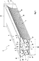
- An inventive carrier 1 is according to a in Fig. 1 constructed structure.
- the support 1 for a lens arrangement 2 of a lighting device comprises a first side wall 3 and a second side wall 4 arranged opposite the first side wall 3. Between the first side wall 3 and the second side wall 4 is a support wall 5 connecting the first side wall 3 and the second side wall 4 positioned.
- the support wall 5 is arranged opposite to a connecting the first side wall 3 and the second side wall 4 mounting wall 6 is formed.
- the first side wall 3, the second side wall 4, the support wall 5 and the mounting wall 6 are arranged at a distance from each other so that a cavity 8 extending along a longitudinal axis 7 of the support 1 is formed between them.
- the walls 3, 4, 5, 6 are made in one piece with each other in a pultrusion process. This favors a tightness of the cavity 8 against penetrating moisture and / or moisture, since the walls 3, 4, 5, 6 without the aid of a sealant are positively and materially connected to each other.
- a further advantage is that the carrier 1 can be produced as an endless profile and sections to be cut to an appropriate length.
- Fig. 2 shows the carrier 1 in a cross section.
- the cavity 8 has a first partition 9 and a second partition 10, which extend transversely, in this embodiment, perpendicular to the longitudinal axis 7 and in the direction of the longitudinal axis 7.
- the first partition wall 9 and the second partition wall 10 are spaced from each other axially and in parallel. With the help of the two partitions 9, 10, the cavity 8 divides into three cavity cells, a first cavity cell 11, a second cavity cell 12 and a third cavity cell 13.
- the carrier 1 is equipped for mounting on a rope or a pole with corresponding receiving elements.
- the first partition 9 and the second partition 10 each have a bearing profile 14.
- This bearing profile 14 is suitable for receiving a mast with a round cross section.
- the bearing profile 14 is formed in the form of a partial circle, wherein the first partition wall 9 and the second partition wall 10 of this part-circular bearing profile 14 each have along the longitudinal axis 7 mirrored to each other.
- the bearing profile 14 may be formed adapted to a standard for mast sections.
- the support wall 5 has along the longitudinal axis 7 extending, the cavity 8 facing grooves 15 formed.
- the grooves 15 have a specific groove profile 16, in which firmly connected to a rope, the groove profile 16 form-fitting adapted not shown rope elements are inserted.
- the carrier 1 is flexibly mountable on carrier devices such as mast or rope without the additional changes to the carrier 1 are made. Furthermore, retaining elements 30 can be attached to the support 1 for easy ceiling mounting, the support wall 5 serving to receive the retaining elements 30.
- the holding members 30 are formed in the form of U-shaped support angle. These are connected to the support wall 5 facing the formed angular surface by means of a releasable connection, which is a screw in the second embodiment, connected to the carrier 1.
- a releasable connection which is a screw in the second embodiment, connected to the carrier 1.
- the holding member 30 is formed in two parts, so that a first holding element part 31 on a ceiling, not shown, for example. A tunnel ceiling, and the second holding element part 32 is mounted on the carrier 1.
- the first holding element part 31 and the second holding element part 32 are connected to one another by means of a screw connection.
- mutually facing ends of the first holding element part 31 and the second holding element part 32 are complementary in the form of a snap or clip connection.
- the carrier 1 with the second holding element part 32 is to be correspondingly positioned on the first holding element part 31 and can be brought into its final assembly position by, for example, a short pressing with audible latching and latching of the holding element parts 31, 32, so that the carrier 1 easily mounted quickly in its intended location.
- the cavity 8 facing tubular formed longitudinal grooves 17 between wall longitudinal edges 33 of the support wall 5 and the first side wall 3, the support wall 5 and the second side wall 4, the mounting wall 6 and the first side wall 3 and the mounting wall 6 and the second side wall 4 configured ,
- These longitudinal grooves 17 are thus assigned in this embodiment, the first cavity cell 11 and the third cavity cell 13.
- the longitudinal grooves 17 are likewise positioned on a first partition wall surface 18 of the first partition wall 9 facing the first cavity cell 11 and on a second partition wall surface 19 of the second partition wall 10 facing the third cavity cell 13 on the bearing profiles 14 of the partition walls 9, 10.
- the longitudinal grooves 17 can serve to receive electrical cables and lines, so that a power supply unit for a power supply to a lens assembly 2 mounted on the mounting wall surface 20 facing away from the cavity 8 can be connected to one of the cavity cells 11, 13.
- the mounting wall 6 receiving openings not shown in detail, which completely penetrate the mounting wall 6 in their wall thickness.
- the receiving openings are made in the form of holes.
- protective sleeves are arranged in the receiving openings. These protective sleeves also serve at the same time to seal against moisture, for example condensation water, which could penetrate between the mounting wall surface 20 and a bottom surface of the lens arrangement 2, not shown, which is connected to the mounting wall surface 20.
- the facing away from the ceiling at a ceiling mounting on the support, thus lying below mounting wall has a planar mounting wall surface 20, which is remote from the support wall 5.
- the support brackets 30 are mounted on the support wall 5 on its side facing away from the cavity 8 formed support wall surface 29.
- Fig. 3 On the first mounting panel are gem.
- Fig. 3 several lens assemblies 2 mounted.
- the lens arrangements 2 have light-emitting diode receiving lenses 21 which are not illustrated in more detail and which are arranged in the form of a matrix.
- the lenses 21 with the LEDs could also be positioned side by side or one behind the other in the form of a row. This depends on a surface to be illuminated or a room to be illuminated.
- the carrier 1 is shown with attached to the mounting wall 6 seven lens assemblies 2 in a bottom view.
- Each lens arrangement 2 has fifteen light-emitting diodes, each accommodated in a lens 21, which are arranged according to a 3 ⁇ 5 matrix.
- the cavity 8 and thus the electrical supply of the lens assembly 2 are protected from penetrating moisture and moisture and dirt, the cavity 8 at one end of the carrier 1 and the other end of the carrier 1 by means of a first lid 23 and a second lid 24 can be closed.
- the lid 23, 24 are fixed by means of a clamping device, not shown, which is in the form of conically formed bolts not shown in detail, on the carrier 1.
- the bolts are received in the longitudinal grooves 17, which are formed on the wall longitudinal edges 33.
- the lid 23, 24 could also be mounted on the carrier 1 with the aid of a detachable screw connection.
- the side wall surfaces 25, 26 are each formed on the side walls 3, 4 facing away from the cavity 8.
- the first side wall 3 and the second side wall 4 are formed in their transverse extension relative to the cavity 8 concave.
- the side walls 3, 4 extend in their extension along the longitudinal axis 7 in the direction of the x-coordinate.
- the transverse extent corresponds to its extension in the direction of the y-coordinate, while an extension in the direction of the z-coordinate corresponds to a wall thickness of the side walls 3, 4.
- the first side wall 3 and the second side wall 4 are in their expansion formed between the support wall 5 and the mounting wall 6, i. in its transverse extent, extending from the support wall 5 extending over the mounting wall 6 of time away.
- This has the advantage that guide rails 27 are configured on the mounting wall surface 20 in the direction of the longitudinal axis 7 for positioning the lens arrangement 2.
- the guide rails 27 have a reinforced wall thickness, since in the region of the guide rails 27, a large heat input of the lens assembly 2 prevails during operation of the lamp.
- first section can be used in particular for heat dissipation in the form of heat radiation.
- the heat radiated from the first section can be at least partially released to the environment without hitting the carrier 1 or the side wall 3, 4.
- the support wall 5 has a first width B1, which is greater than a second width B2 of the mounting wall 6.
- the side walls 3, 4 could extend beyond the support wall 5 in their transverse extent. In this case, a corresponding total height H of the carrier 1 is to be observed.
- the sections of the side walls 3, 4 which extend beyond the support wall 5 are ideally to be arc-shaped, so that an overall height extension possibly increased on account of the sections is avoided. Depending on the radius R formed in the concavity, this can be continued, for example, or the sections have a generally smaller radius of curvature, so that the total height H is maintained.
- the carrier 1 is made of an aluminum material, EN AW-6060, ideally as a hollow profile.
- EN AW-6060 is a standard AlMgSi group aluminum alloy with 0.35-0.6% magnesium as the main constituent and additions of silicon, iron, zinc, titanium, manganese, copper and chromium.
- AlMgSi alloys are the most commonly used hardenable aluminum wrought alloys. By means of various hardening treatments, medium to high strengths can be achieved according to use. In particular, this aluminum material is characterized by good cold workability and high corrosion resistance.
- the carrier 1 has a surface treatment, wherein the surface treatment in the illustrated embodiment is an anodization.
- the carrier 1 could be surface-treated with an anticorrosive coating material, for example in the form of a lacquer.
- the mounting panel 20 is planar, i. just designed.
- the on a non-illustrated circuit board matrix-like positioned lenses 21 with light emitting diodes of the lens assembly 2 are easily and securely fixed to the mounting wall 6.
- Between the circuit board and the mounting panel 20 is airtightness.
- the lens assembly 2 is attached to the mounting panel 20 with an adhesive.
- the ribs 28, due to turbulence generated by the ribs 28 on the side wall surfaces 25, 26, serve to provide improved free convection to release the thermal load created by the electrical supply of the light emitting diodes and associated light and associated heat to the environment to be able to.
- the covers 23, 24 have, in addition to venting and drainage openings 34, a connection 35 for the electrical connection of the power supply, such as an improved representation of the detailed view in FIG Fig. 6 can be removed.
- the carrier has lids 23, 24, which in addition to the venting and drainage openings 34 further ventilation openings 34 'in the region of the first cavity cell 11 and in the region of the third cavity cell 13 have.
- the vent openings 34 ' are formed lssensnutartig, wherein a plurality of longitudinal grooves are arranged parallel to each other.
- the second cover 24 is shown with a connection opening 36 for receiving the connection 35.
- the first lid 23 with the vent openings 34 ' is also to produce. This is particularly advantageous in the case of very long carriers 1 and serves in a simple way to dissipate heat in the first cavity cell 11 and the third cavity cell 13, so that cooling of the second cavity cell 12 is likewise formed by free convection on the dividing walls 9, 10.
- the lid In addition to a recorded in a pin opening 36 by means of a press fit pins 38 for fixing the cover 24 to the mounting wall 6, the lid has various mounting holes 39, by means of which the cover 24 on the side walls 3, 4, on the support wall 5 and on the Mounting wall 6 can be fixed.
- the pin 38 extends in its longitudinal direction, starting from a cover inner surface 41 in the direction of the cavity 8.
- a lid outer surface 40, which faces away from the lid inner surface 41, is flat or planar.
- a forced by means of the vent openings 34 'flow in the cavity 8, starting from the mounting wall 6 in the direction of the support wall 5 may be formed, for example.
- relatively short carriers 1 ambient air for cooling the cavity 8 in the area the mounting wall 6 formed vent openings 34 'flows into the cavity 8 and heated by the formed in the region of the support wall 5 vent openings 34' flows out of the cavity 8.
Landscapes
- Engineering & Computer Science (AREA)
- General Engineering & Computer Science (AREA)
- Arrangement Of Elements, Cooling, Sealing, Or The Like Of Lighting Devices (AREA)
Description
- Die Erfindung betrifft einen Träger für eine Linsenanordnung einer Beleuchtungsvorrichtung nach dem Oberbegriff des Patentanspruchs 1.
- Träger für eine Linsenanordnung einer Beleuchtungsvorrichtung, insbesondere einer Beleuchtungsvorrichtung für eine Tunnelbeleuchtung, wobei die Linsenanordnung eine Mehrzahl von Leuchtdioden aufweisende Linsen umfasst, sind bekannt. Beleuchtungsmittel wie bspw. Glühbirnen setzen Wärme insbesondere an ihren lichtemittierenden Flächen frei. Dies führt zu einer Wärmebelastung eines das Beleuchtungsmittel aufnehmenden Trägers. Insbesondere Leuchtdioden, so genannte LEDs, sind in bspw. einer Linse aufgenommen. Zur Erzielung einer großen ausgeleuchteten Fläche sind die Leuchtdioden aufweisenden Linsen in einer Mehrzahl nebeneinander angeordnet, so dass eine hohe Wärmemenge insbesondere an einer Befestigungsfläche der Linse abgegeben wird, die es von dem Leuchtmittel über den Träger abzuführen gilt.
- So geht beispielsweise aus der Offenlegungsschrift
DE 10 2010 045 297 A1 ein Träger für eine Linsenanordnung einer Tunnelleuchte hervor. Die Tunnelleuchte umfasst ein in einem Träger aufgenommenes, unabhängig vom Träger ausgebildetes Halteprofil, welches Leuchtmodule aufnehmbar ausgestaltet ist. Die Leuchtmodule bestehen in einer Mehrzahl von Leuchtdioden. Eine Wärmeabfuhr erfolgt sowohl über das Halteprofil als auch über den Träger, welcher das Halteprofil aufnimmt. - Die Offenlegungsschrift
DE 10 2011 111 953 A1 offenbart ebenfalls einen Träger für eine Linsenanordnung einer Tunnelleuchte, wobei der Träger eine Linsenanordnung aufnehmbar gestaltet ist. Der Träger ist hohlprofilartig ausgebildet, wobei die Linsenanordnung unmittelbar am Träger zu befestigten ist, so dass ein unabhängig vom Träger ausgebildetes Halteprofil abdingbar ist, wodurch sich Herstellungskosten reduzieren. Der Träger weist zwei Seitenwände auf, zwischen welchen sich eine Trägerwand zur Befestigung des Trägers und eine Montagewand zur Befestigung der Linsenanordnung am Träger befinden. Sowohl die Seitenwände als auch die Trägerwand und die Montagewand sind voneinander beabstandet, so dass zwischen ihnen ein Hohlraum ausgebildet ist. Der Träger weist in seinem Querschnittsprofil bezüglich des Hohlraumes konvex ausgebildete Seitenwände bzw. Seitenwände mit einer Außenwölbung sowie eine an den Seitenwänden den Träger prägend ausgebildete Rippenstruktur zur Wärmeabfuhr auf. -
DE 20 2011 003 828 U1 offenbart einen Träger für eine Linsenanordnung einer Beleuchtungsvorrichtung umfassend eine erste Seitenwand und eine der ersten Seitenwand gegenüberliegend angeordnete zweite Seitenwand, wobei zwischen der ersten Seitenwand und der zweiten Seitenwand eine die erste Seitenwand und die zweite Seitenwand verbindende Trägerwand und eine der Trägerwand gegenüberliegend angeordnete die erste Seitenwand und die zweite Seitenwand verbindende Montagewand, wobei die erste Seitenwand, die zweite Seitenwand, die Trägerwand und die Montagewand voneinander beabstandet ausgebildet sind und zwischen ihnen ein sich entlang einer Längsachse des Trägers erstreckender Hohlraum ausgebildet ist, wobei bezogen auf den Hohlraum die erste Seitenwand und/oder die zweite Seitenwand in ihrer Quererstreckung gekrümmt ausgebildet sind. -
US 2013/0170209 A1 offenbart einen Träger für eine Linsenanordnung umfassend eine erste Seitenwand und eine der ersten Seitenwand gegenüberliegend angeordnete zweite Seitenwand, wobei zwischen der ersten Seitenwand und der zweiten Seitenwand eine die erste Seitenwand und die zweite Seitenwand verbindende Trägerwand und eine der Trägerwand gegenüberliegend angeordnete die erste Seitenwand und die zweite Seitenwand verbindende Montagewand, wobei die erste Seitenwand, die zweite Seitenwand, die Trägerwand und die Montagewand voneinander beabstandet ausgebildet sind und zwischen ihnen ein sich entlang einer Längsachse des Trägers erstreckender Hohlraum ausgebildet ist, wobei bezogen auf den Hohlraum die erste Seitenwand und/oder die zweite Seitenwand in ihrer Erstreckung konkav gekrümmt ausgebildet sind. -
US 2012/0229025 A1 offenbart ein Profil, welches als Träger für eine Linsenanordnung geeignet ist, jedoch nicht für diesen Zweck vorgesehen ist. - Aufgabe der vorliegenden Erfindung ist es einen Träger für eine Linsenanordnung einer Beleuchtungsvorrichtung bereitzustellen, welcher eine verbesserte Wärmeableitung bei gleichzeitig einfachem Aufbau aufweist.
- Die Aufgabe wird erfindungsgemäß durch einen Träger für eine Linsenanordnung einer Beleuchtungsvorrichtung mit den Merkmalen das Patentanspruchs 1 gelöst. Vorteilhafte Ausgestaltungen mit zweckmäßigen und nicht-trivialen Weiterbildungen der Erfindung sind in den jeweiligen Unteransprüchen angegeben.
- Der erfindungsgemäße Träger für eine Linsenanordnung einer Beleuchtungsvorrichtung weist eine erste Seitenwand und eine der ersten Seitenwand gegenüberliegend angeordnete zweite Seitenwand auf, wobei zwischen der ersten Seitenwand und der zweiten Seitenwand eine Trägerwand und eine der Trägerwand gegenüberliegend angeordnete Montagewand ausgebildet sind. Die erste Seitenwand und die zweite Seitenwand werden mit Hilfe der Trägerwand und der Montagewand miteinander verbunden. Die erste Seitenwand, die zweite Seitenwand, die Trägerwand und die Montagewand sind voneinander beabstandet angeordnet, so dass zwischen ihnen ein sich entlang einer Längsachse des Trägers erstreckender Hohlraum ausgebildet ist. Die erste Seitenwand und/oder die zweite Seitenwand sind bezogen auf den Hohlraum in ihrer Quererstreckung konkav ausgebildet. Mit anderen Worten weisen die erste Seitenwand und/oder die zweite Seitenwand in ihrem Profil eine Innenwölbung bezogen auf den Hohlraum auf. Diese Innenwölbung der Seitenwände bzw. die konkave Krümmung der Seitenwände bezogen auf den Hohlraum hat den wesentlichen Vorteil, dass sich ihre zur freien Konvektion vorgesehenen Flächen zur Wärmeabfuhr einer bei Betrieb der Beleuchtungsvorrichtung durch die Linsenanordnung erzeugten Wärme auf einfache Weise vergrößern lassen ohne einen benötigten Bauraumbedarf des Trägers zu verändern.
- Die bei einem Betrieb der Beleuchtungsvorrichtung durch die Linsenanordnung erzeugte Wärme wird über Wärmeleitung ausgehend von den Linsen auf die Montagewand und von dort weiter über die Seitenwände und die Trägerwand des Trägers übertragen. Hinzu kommt eine Wärmeabgabe in den Hohlraum des Trägers. Diese sich durch die Wärmeleitung ansammelnde Wärmemenge gilt es so schnell wie möglich an eine Umgebung der Beleuchtungsvorrichtung abzuführen, da es ansonsten unter Umständen neben einer Schädigung des Trägers zu bspw. Schädigungen von Linsen und in den Linsen aufgenommenen Leuchtdioden oder von im möglicherweise Hohlraum angeordneten Kabeln kommen kann.
- Grundsätzlich gilt, dass eine schnelle Wärmeabfuhr mit Hilfe einer großen Oberfläche durch freie Konvektion und Wärmestrahlung realisierbar ist. Aufgrund einer Wölbung der Seitenwände lässt sich auf einfache Weise eine vom Hohlraum abgewandt ausgebildete erste Seitenfläche der ersten Seitenwand bzw. eine vom Hohlraum abgewandt ausgebildete zweite Seitenfläche der zweiten Seitenwand vergrößern. Durch die relativ zum Hohlraum konkav ausgebildete Seitenwand ist es möglich den vorgesehenen Bauraumbedarf der Beleuchtungsvorrichtung bzw. Leuchte einzuhalten und dennoch eine Vergrößerung der zur Konvektion vorgesehenen ersten Seitenfläche bzw. zweiten Seitenfläche zu erzielen. Das bedeutet, dass lediglich die Seitenwände in ihrer Krümmung zu verändern sind um eine einer Leistung der Linsenanordnung angepasste Wärmeabfuhr zu erlangen.
- Wird die Beleuchtungsvorrichtung beispielsweise als Tunnelleuchte eingesetzt, so weisen im Allgemeinen die Tunnel eine typische Tunnelwölbung auf. Das heißt, die Tunnel sind in ihrem Querschnitt in der Regel nicht rechteckig oder quadratisch ausgebildet, sondern parabelformartig gestaltet. Ausgehend von einer Fahrbahn wird in Richtung einer Tunneldecke ein sich quer zu einer Tunnellängsachse ausgebildeter möglicher Bauraum immer geringer. Das heißt, dass eine beispielsweise relativ zum Hohlraum konkav ausgebildete Seitenwand eine Begrenzung durch eine Tunnelwandung erfahren würde. Die konkav ausgebildete erste Seitenwand bzw. zweite Seitenwand jedoch kann sich zur Erzielung einer ausreichenden Oberfläche zur Wärmeabfuhr in Richtung des Hohlraumes hin erstrecken.
- In einer Ausgestaltung des erfindungsgemäßen Trägers weist die Trägerwand eine erste Breite auf, die größer ist, als eine zweite Breite der Montagewand. Das bedeutet in einem Querschnitt des Trägers, dass im Bereich der Trägerwand ausgebildete erste Abschnitte der Seitenwände sich in ihrer Quererstreckung über ihren im Bereich der Montagewand ausgebildeten zweiten Abschnitten erstrecken. Dies hat insbesondere bei einer an einer Tunneldecke angebrachten Beleuchtungsvorrichtung den Vorteil, dass die ersten Abschnitte der Seitenwände die Wärme ungehindert an einen freien Tunnelraum, welcher zwischen der Tunneldecke und zwischen der Tunneldecke und der Fahrbahn ausgebildeten Tunnelwandung ausgebildet ist, abgeben können.
- Ein zusätzlicher Vorteil dieser Ausgestaltung ist eine weiter verbesserte Wärmeableitung. Dem Grundsatz des Aufstiegs erwärmter Luft folgend, steigt mindestens die abgeführte Wärme entlang den konkav ausgebildeten Seitenwänden in Richtung der Trägerwand, wobei sie aufgrund der Konkavität einen Richtungswechsel ihrer Strömungsrichtung zur verbesserten Abfuhr erfährt. An Schnittkanten zwischen den Seitenwänden und der Trägerwand wird die Wärme aufgrund der größeren ersten Breite der Trägerwand in ihrer Strömungsrichtung weg von der Trägerwand und insgesamt weg vom Träger geführt. Die größere erste Breite der Trägerwand erzielt einen in Richtung des Hohlraums ausgebildeten spitzen Winkel zwischen der Trägerwand und der Seitenwand, so dass die Strömungsrichtung der abzuführenden Wärme im Bereich der Schnittkante gegenüber der Umgebung einen stumpfen Winkel relativ zur Trägerwand aufweist. Je nach Verhältnis der ersten Breite und der zweiten Breite und dem Radius der Konkavität kann die Wärme an der Schnittkante tangential zur Trägerwand abgeführt werden.
- Ein weiterer Vorteil ergibt sich aufgrund der weitestgehend eben vom Hohlraum abgewandten Trägerwandfläche der Trägerwand, ist zwischen der Tunneldecke und der Trägerwandfläche ein Strömungskanal ausgebildet, welcher den Umgebungsbedingungen entsprechend eine Strömung der Umgebungsluft aufweist, so dass hier quasi eine erzwungene Konvektion ausgebildet ist. Dies fördert eine schnelle Wärmeabfuhr der an die Trägerwand abgegebenen Wärme der Linsenanordnung.
- In einer Ausgestaltung des erfindungsgemäßen Trägers sind die erste Seitenwand und/oder die zweite Seitenwand in ihrer zwischen der Trägerwand und der Montagewand ausgebildeten Ausdehnung sich ausgehend von der Trägerwand über die Montagewand hinweg erstreckend ausgebildet. Dadurch ist die Möglichkeit einer weiteren Vergrößerung der wärmeabgebenden ersten Seitenfläche bzw. zweiten Seitenfläche durch die sich von der maximalen Tunnelhöhe bzw. eine im Tunnel ausgebildete Deckenwandung abgewandt ausgebildete Erstreckung zu erzielen.
- Ein weiterer Vorteil dieser über die von der Trägerwand abgewandt ausgebildete Ausdehnung über die Montagewand hinaus ist eine Positionier- und Haltehilfe für die Linsenanordnung, welche somit zwischen der Ausdehnung der ersten Seitenwand und der zweiten Seitenwand ausgebildet ist. Das heißt mit anderen Worten, dass die erste Seitenwand und die zweite Seitenwand in ihrer Ausdehnung ausgehend von der Trägerwand in Richtung der Montagewand so groß ausgebildet ist, dass an einer von der Trägerwand abgewandt ausgebildeten ersten Montagewandfläche sich in Richtung der Längsachse erstreckende Führungsleisten ausgestaltet sind, die eine über die Montagewand hinausgehende Erstreckung der Seitenflächen bilden.
- Eine weitere zusätzliche Verbesserung der Wärmeabfuhr ist mit Rippen herbeizuführen, welche an einer Außenfläche der ersten Seitenwand bzw. der zweiten Seitenwand ausgebildet sind. Mit anderen Worten weisen die erste Seitenwand und/oder die zweite Seitenwand an ihrer vom Hohlraum abgewandt ausgebildeten ersten Seitenwandfläche bzw. zweiten Seitenwandfläche Rippen auf. Mit Hilfe der Rippen werden Verwirbelungen an der ersten Seitenwandfläche und der zweiten Seitenwandfläche erzeugt, welche die Konvektion begünstigen. In einer vorteilhaften Ausgestaltung erstrecken sich die Rippen entlang der Längsachse und sind somit einfach in einem bspw. Strangpressverfahren herstellbar.
- Der Hohlraum ist mit Hilfe einer Trennwand in mindestens zwei Hohlräume getrennt, so dass er vorteilhaft zur Aufnahme von einerseits elektrischen Bauteilen, wie beispielsweise Netzteile, Kabel zur Stromversorgung, sowie weitere einer elektrischen Leitung dienenden Bauteile und andererseits zur Aufnahme mechanischen Bauteilen von beispielweise Träger- und/oder Linsenanordnungsbefestigungen dienen kann. Somit lassen sich auf einfache Weise elektrische und rein mechanische Bauteile getrennt innerhalb des Trägers unterbringen.
- Erfindungsgemäß weist der Hohlraum eine sich entlang der Längsachse erstreckende erste Trennwand und eine sich entlang der Längsachse erstreckende, der ersten Trennwand gegenüberliegende und von der ersten Trennwand beabstandete zweite Trennwand auf, wobei die erste Trendwand und die zweite Trennwand jeweils mit einem Lagerprofil ausgestattet sind. Mit Hilfe des Lagerprofils dienen die erste Trennwand und die zweite Trennwand einer Lagerung des Trägers. Soll der Träger an einem standardisierten Leuchtenmast angebracht werden, wie beispielsweise einem Mast einer Straßenleuchte oder einem Mast auf einem Rollfeld eines Flughafens, so ist das Lagerprofil der beiden Trennwände komplementär zu einem Umfang eines runden Querschnitts des Mastes ausgebildet. Das bedeutet, dass der Träger aufgrund seiner besonderen Ausgestaltung der Trennwände gleichzeitig ein Aufnahmemittel zur Aufnahme des Trägers an einem Masten besitzt.
- Des Weiteren dienen die Trennwände als Strukturelemente zur Realisierung einer verbesserten Steifigkeit und Stabilität des Trägers, so dass die Seitenwände, die Montagewand und die Trägerwand mit einer relativ geringen Wandstärke ausgebildet werden können. Dies wiederum dient einer Kosten- und Gewichtsreduzierung.
- An der Trägerwand sind sich entlang der Längsachse erstreckende, von dem Hohlraum abgewandt ausgebildete Nuten ausgestaltet. In diesen Nuten können zur Nut formschlüssig und/oder komplementär ausgebildete Aufnahmeelement eingeführt werden, welche mit beispielsweise einem Seil verbindbar sind. Somit bietet der Träger die Möglichkeit einer einfachen Montage an einem Seil.
- Ein weiterer Vorteil der Nuten ist, dass sie ebenso für einen Geräteträger nutzbar sind, welcher im Hohlraum bzw. in einem der Hohlraumzellen aufgenommen ist. Das heißt, der Geräteträger ist an den Nuten mit Hilfe eines entsprechenden zur Nut formschlüssig ausgebildeten und in der Nut aufgenommenen Aufnahmeelementes am Träger unbewegbar fixiert.
- Die Montagewand weist Aufnahmeöffnungen auf, wobei die Aufnahmeöffnungen die Montagewand in ihrer Wanddicke vollständig durchdringend ausgebildet sind. An einer vom Hohlraum abgewandt ausgebildeten Seitenfläche ist die Linsenanordnung am Träger zu befestigen. Elektrische Leitungen, welche der Stromzufuhr der Linsenanordnung dienen, können sicher geschützt vor Umwelteinflüssen wie bspw. Nässe im Hohlraum aufgenommen werden. Mit Hilfe der Aufnahmeöffnungen können die Leitungen auf einfache Weise ausgehend von der Linsenanordnung in den Hohlraum geführt werden, bzw. aus dem Hohlraum zu der Linsenanordnung geführt werden. Zur weiteren Sicherung gegen Umwelteinflüsse weisen de Aufnahmeöffnungen Schutzhüllen auf, welche vorteilhafterweise aus einem Kunststoff, idealerweise Gummi hergestellt sind. Gummi bietet den Vorteil, dass er nicht leitfähig ist bei gleichzeitig hoher Elastizität, so dass er formschlüssig und dichtend in die Aufnahmeöffnungen eingebracht werden kann. Des Weiteren dienen diese Aufnahmeöffnungen einer Befestigung der Linsenanordnung.
- Zum Schutz gegenüber eindringender Nässe oder Feuchtigkeit sowie Staub oder weiteren Partikel ist der Hohlraum einends des Trägers und anderenends des Träger mit Hilfe eines ersten Deckels bzw. eines zweiten Deckels verschließbar. Die Deckel sind dabei abnehmbar an den Seitenwänden, der Trägerwand und/oder der Montagewand angeordnet.
- In einer weiteren Ausgestaltung des erfindungsgemäßen Trägers ist der Träger aus einem Aluminiumwerkstoff hergestellt. Aluminiumwerkstoffe zeichnen sich allgemein durch ihre geringe Dichte aus, so dass selbst große Bauteile ein gegenüber bspw. Stahl geringes Gewicht aufweisen. Des Weiteren weisen Aluminiumwerkstoffe aufgrund ihrer hohen Wärmeleitfähigkeit ein sehr gutes Preis-Leistungsverhältnis auf, so dass ein kostengünstiger Träger bei gleichzeitig hoher Wärmeabfuhr herstellbar ist.
- Zu Aufnahme einer mehrreihigen bzw. matrixartigen Linsenanordnung ist es vorteilhaft eine Montagewandfläche der Montagewand plan auszubilden, so dass eine flächige und einfache Montage der Linsenanordnung möglich ist. Zur gesicherten Verbindung der Linsenanordnung an der Montagewand bzw. an der Montagewandfläche kann einerseits eine Schraubverbindung dienen. Allerdings ist bevorzugt eine stoffschlüssige Verbindung in Form von Kleben anzuwenden, wobei hier auf eine Luftdichtheit zwischen der Montagewandfläche und der Linsenanordnung zu achten ist.
- In einer weiteren Ausgestaltung des erfindungsgemäßen Trägers weist der Träger insbesondere an seiner ersten Seitenwandfläche, seiner zweite Seitenwandfläche, seiner Trägerwandfläche und seiner Montagewandfläche eine Oberflächenbehandlung auf zum Schutz gegen Umwelteinflüsse und zur Korrosionsbeständigkeit. Das bedeutet, dass der Träger bzw. die Beleuchtungsvorrichtung in Küstengebieten und Seenähe bspw. Häfen einsetzbar ist, wo ein ausgeprägt korrosiver hoher Salzgehalt der Umgebungsluft vorherrscht. Diese Oberflächenbehandlung kann in Form einer Beschichtung ausgebildet sein, welche zusätzlich den Vorteil aufweist die wärmeabgebende Oberfläche zu vergrößern. Ebenso kann die Oberflächenbehandlung mit einem Eloxalverfahren zur Erzeugung einer oxidischen Schutzschicht des Aluminiumwerkstoffs realisiert sein.
- Weitere Vorteile, Merkmale und Einzelheiten der Erfindung ergeben sich aus der nachfolgenden Beschreibung bevorzugter Ausführungsbeispiele sowie anhand der Zeichnung. Die vorstehend in der Beschreibung genannten Merkmale und Merkmalskombinationen sowie die nachfolgend in der Figurenbeschreibung genannten und/oder in den Figuren alleine gezeigten Merkmale und Merkmalskombinationen sind nicht nur in der jeweils angegebenen Kombination, sondern auch in anderen Kombinationen oder in Alleinstellung verwendbar, ohne den Rahmen der Erfindung zu verlassen. Gleichen oder funktionsgleichen Elementen sind identische Bezugszeichen zugeordnet. Aus Gründen der Übersichtlichkeit ist es möglich, dass die Elemente nicht in allen Figuren mit ihrem Bezugszeichen versehen sind, ohne jedoch ihre Zuordnung zu verlieren. Es zeigen:
- Fig. 1
- in einer perspektivischen Ansicht einen erfindungsgemäßen Träger,
- Fig. 2
- in einem Querschnitt den Träger gem.
Fig. 1 , - Fig. 3
- in einer Unteransicht ein erfindungsgemäßer Träger in einem zweiten Ausführungsbeispiel mit einer Linsenanordnung,
- Fig. 4
- in einer Seitenansicht den Träger gem.
Fig. 3 mit einer Deckenbefestigungsvorrichtung, - Fig. 5
- in einer perspektivischen Ansicht den Träger gem.
Fig. 4 , - Fig. 6
- in einer perspektivischen Ansicht einen Ausschnitt im Bereich eines Deckels des Trägers gem.
Fig. 5 , - Fig. 7
- in einer Draufsicht einen Deckel eines erfindungsgemäßen Trägers in einem dritten Ausführungsbeispiel, und
- Fig. 8
- in einem Schnitt entlang einer Schnittebene VIII-VIII den Deckel gem.
Fig. 7 . - Ein erfindungsgemäßer Träger 1 ist gemäß einer in
Fig. 1 dargestellten Struktur aufgebaut. Der Träger 1 für eine Linsenanordnung 2 einer Beleuchtungsvorrichtung umfasst eine erste Seitenwand 3 und eine der ersten Seitenwand 3 gegenüberliegend angeordnete zweite Seitenwand 4. Zwischen der ersten Seitenwand 3 und der zweiten Seitenwand 4 ist eine die erste Seitenwand 3 und die zweite Seitenwand 4 verbindende Trägerwand 5 positioniert. Der Trägerwand 5 gegenüberliegend angeordnet ist eine die erste Seitenwand 3 und die zweite Seitenwand 4 verbindende Montagewand 6 ausgebildet. - Die erste Seitenwand 3, die zweite Seitenwand 4, die Trägerwand 5 und die Montagewand 6 sind voneinander beabstandet angeordnet, so dass zwischen ihnen ein sich entlang einer Längsachse 7 des Trägers 1 erstreckender Hohlraum 8 ausgebildet ist. Die Wände 3, 4, 5, 6 sind miteinander einstückig in einem Strangziehverfahren hergestellt. Dies begünstigt eine Dichtheit des Hohlraums 8 gegenüber eindringender Nässe und/oder Feuchtigkeit, da die Wände 3, 4, 5, 6 ohne Zuhilfenahme eines Dichtmittels form- und stoffschlüssig miteinander verbunden sind. Vorteilhaft ist weiterhin, dass der Träger 1 als Endlosprofil herstellbar und abschnittsweise auf eine entsprechende Länge zuzuschneiden ist.
-
Fig. 2 zeigt den Träger 1 in einem Querschnitt. Der Hohlraum 8 weist eine erste Trennwand 9 und eine zweite Trennwand 10 auf, welche sich quer, in diesem Ausführungsbeispiel senkrecht zur Längsachse 7 und in Richtung der Längsachse 7 erstrecken. Die erste Trennwand 9 und die zweite Trennwand 10 sind voneinander axial und parallel beabstandet angeordnet. Mit Hilfe der beiden Trennwände 9, 10 teilt sich der Hohlraum 8 in drei Hohlraumzellen, eine erste Hohlraumzelle 11, eine zweite Hohlraumzelle 12 und eine dritte Hohlraumzelle 13. - Der Träger 1 ist zur Montage an einem Seil oder einem Masten mit entsprechenden Aufnahmeelementen bestückt. Der erste Trennwand 9 und die zweite Trennwand 10 weisen je ein Lagerprofil 14 auf. Dieses Lagerprofil 14 ist zur Aufnahme eines Masten mit einem runden Querschnitt geeignet. In diesem Ausführungsbeispiel ist das Lagerprofil 14 in Form eines Teilkreises ausgebildet, wobei die erste Trennwand 9 und die zweite Trennwand 10 dieses teilkreisförmige Lagerprofil 14 jeweils entlang der Längsachse 7 gespiegelt zueinander aufweisen. Das Lagerprofil 14 kann einer Norm für Mastquerschnitte angepasst ausgebildet sein.
- Zusätzlich zu diesem Lagerprofil 14 weist die Trägerwand 5 sich entlang der Längsachse 7 erstreckende, dem Hohlraum 8 zugewandt ausgebildete Nuten 15 auf. Die Nuten 15 haben ein bestimmtes Nutprofil 16, in welches mit einem Seil fest verbunden, dem Nutprofil 16 formschlüssig angepasste nicht näher dargestellte Seilelemente einführbar sind.
- Mit der Ausbildung der Nuten 15 und der Lagerprofile 14 ist der Träger 1 flexibel an Trägervorrichtungen wie bspw. Mast oder Seil montierbar ohne das zusätzliche Änderungen am Träger 1 vorzunehmen sind. Des Weiteren können am Träger 1 Halteelemente 30 zur einfachen Deckenmontage angebracht werden, wobei die Trägerwand 5 zur Aufnahme der Halteelemente 30 dient.
- Wie ein in den
Figuren 3 bis 5 dargestelltes zweites Ausführungsbeispiel zeigt, sind die Halteelemente 30 in Form von u-förmigen Trägerwinkel ausgebildet. Diese werden an ihrer der Trägerwand 5 zugewandt ausgebildeten Winkelfläche mit Hilfe einer lösbaren Verbindung, welche in dem zweiten Ausführungsbeispiel eine Schraubverbindung ist, mit dem Träger 1 verbunden. Zur einfachen Montage ist das Halteelement 30 zweiteilig ausgebildet, so dass ein erstes Halteelementteil 31 an einer nicht näher dargestellten Decke, bspw. eine Tunneldecke, und das zweite Halteelementteil 32 an dem Träger 1 montiert wird. Im dargestellten Ausführungsbeispiel gem. derFiguren 3 bis 5 , sind das erste Halteelementteil 31 und das zweite Halteelementteil 32 mittels einer Schraubverbindung miteinander verbunden. - In einem nicht näher dargestellten Ausführungsbeispiel sind einander zugewandt ausgebildeten Enden des ersten Halteelementteils 31 und des zweiten Haltelementteils 32 komplementär in Form einer Schnapp- oder Klipsverbindung ausgebildet. Zur Deckenmontage ist der Träger 1 mit dem zweiten Halteelementteil 32 an dem ersten Halteelementteil 31 entsprechend zu positionieren und kann durch bspw. ein kurzes Drücken unter hörbarem Ein- und Verrasten der Halteelementteile 31, 32 in seine endgültige Montageposition gebracht werden, so dass der Träger 1 in einfacher Weise schnell an seinem vorgesehenen Ort montiert ist.
- Des Weiteren sind dem Hohlraum 8 zugewandt rohrartig ausgebildete Längsnuten 17 zwischen Wandlängskanten 33 der Trägerwand 5 und der ersten Seitenwand 3, der Trägerwand 5 und der zweiten Seitenwand 4, der Montagewand 6 und der ersten Seitenwand 3 sowie der Montagewand 6 und der zweiten Seitenwand 4 ausgestaltet. Diese Längsnuten 17 sind somit in diesem Ausführungsbeispiel der erster Hohlraumzelle 11 und der dritte Hohlraumzelle 13 zugeordnet.
- Die Längsnuten 17 sind ebenfalls an einer der ersten Hohlraumzelle 11 zugewandt ausgebildeten ersten Trennwandfläche 18 der ersten Trennwand 9 sowie an einer der dritten Hohlraumzelle 13 zugewandt ausgebildeten zweiten Trennwandfläche 19 der zweiten Trennwand 10 an den Lagerprofilen 14 der Trennwände 9, 10 positioniert.
- Die Längsnuten 17 können der Aufnahme von elektrischen Kabeln und Leitungen dienen, so dass sich ein in einer der Hohlraumzellen 11, 13 aufgenommenes Netzteil zur Energieversorgung einer an der vom Hohlraum 8 abgewandt ausgebildeten Montagewandfläche 20 der Montagewand 6 montierte Linsenanordnung 2 verbinden lässt. Hierzu weist die Montagewand 6 nicht näher dargestellte Aufnahmeöffnungen auf, die die Montagewand 6 in ihrer Wanddicke vollständig durchdringen. In einem einfachen Verfahren sind die Aufnahmeöffnungen in Form von Bohrungen hergestellt. Damit die in den Aufnahmeöffnungen aufgenommenen Kabel und Leitungen gegenüber den im Allgemeinen scharfkantigen Bohrungen vor Abrieb geschützt sind, sind nicht näher dargestellte Schutzhülsen in den Aufnahmeöffnungen angeordnet. Diese Schutzhülsen dienen auch gleichzeitig einer Abdichtung gegenüber Feuchtigkeit, bspw. Kondenswasser, welches zwischen die Montagewandfläche 20 und einer nicht näher dargestellte Bodenfläche der Linsenanordnung 2, welche mit der Montagewandfläche 20 verbunden ist, eindringen könnte.
- Die bei einer Deckenmontage von der Decke abgewandt am Träger ausgebildete, somit unten liegenden Montagewand verfügt über eine plane Montagewandfläche 20, welche von der Trägerwand 5 abgewandt ausgebildet ist. Zur Deckenmontage sind an der Trägerwand 5 an seiner vom Hohlraum 8 abgewandt ausgebildeten Trägerwandfläche 29 die Trägerwinkel 30 montiert.
- Auf der ersten Montagewandfläche sind gem.
Fig. 3 mehrere Linsenanordnungen 2 montiert. Die Linsenanordnungen 2 weisen nicht näher dargestellte Leuchtdioden aufnehmende Linsen 21 auf, welche in Form einer Matrix angeordnet sind. Ebenso könnten die Linsen 21 mit den Leuchtdioden auch nebeneinander oder hintereinander in Form einer Reihe positioniert sein. Dies ist abhängig von einer auszuleuchtenden Fläche bzw. eines auszuleuchtenden Raumes. InFig. 3 ist der Träger 1 mit an der Montagewand 6 befestigten sieben Linsenanordnungen 2 in einer Unteransicht dargestellt. Jede Linsenanordnung 2 weist fünfzehn jeweils in einer Linse 21 aufgenommene Leuchtdioden auf, welche gemäß einer 3 x 5 Matrix angeordnet sind. - Damit der Hohlraum 8 und somit auch die elektrische Versorgung der Linsenanordnung 2 vor eindringender Nässe und Feuchtigkeit sowie Schmutz geschützt sind, ist der Hohlraum 8 einends des Trägers 1 und anderenends des Trägers 1 mit Hilfe eines ersten Deckels 23 bzw. eines zweiten Deckels 24 verschließbar. Die Deckel 23, 24 sind mit Hilfe einer nicht näher dargestellten Klemmvorrichtung, welche in Form konisch ausgebildeter nicht näher dargestellter Bolzen vorliegt, am Träger 1 befestigt. Die Bolzen sind in den Längsnuten 17, welche an den Wandlängskanten 33 ausgebildet sind, aufgenommen. Ebenso könnten die Deckel 23, 24 auch mit Hilfe einer lösbaren Schraubverbindung am Träger 1 montiert sein.
- Eine durch die Linsenanordnung 2 erzeugte Wärme, welche unmittelbar von der Montagewand 6 auf die erste Seitenwand 3 und die zweite Seitenwand 4 durch Wärmeleitung übertragen wird, wird insbesondere mit Hilfe einer ersten Seitenwandfläche 25 der ersten Seitenwand 3 und einer zweiten Seitenwandfläche 26 der zweiten Seitenwand 4 an die Umgebung durch freie Konvektion und Wärmestrahlung zumindest teilweise abgegeben.
- Die Seitenwandflächen 25, 26 sind an den Seitenwänden 3, 4 jeweils vom Hohlraum 8 abgewandt ausgebildet. Zur Realisierung einer großen Oberfläche zur freien Konvektion sind die erste Seitenwand 3 und die zweite Seitenwand 4 in ihrer Quererstreckung relativ zum Hohlraum 8 konkav ausgebildet. Unter Einführung eines kartesischen Koordinatensystems mit den Koordinaten x, y, und z erstrecken sich die Seitenwände 3, 4 in ihrer Erstreckung entlang der Längsachse 7 in Richtung der x-Koordinate. Die Quererstreckung entspricht ihrer Erstreckung in Richtung der y-Koordinate, während eine Erstreckung in Richtung der z-Koordinate einer Wanddicke der Seitenwände 3, 4 entspricht.
- Die erste Seitenwand 3 und die zweite Seitenwand 4 sind in ihrer zwischen der Trägerwand 5 und der Montagewand 6 ausgebildeten Ausdehnung, d.h. in ihrer Quererstreckung, sich ausgehend von der Trägerwand 5 über die Montagewand 6 hinweg erstreckend ausgebildet. Dies hat den einen Vorteil, dass Führungsleisten 27 an der Montagewandfläche 20 in Richtung der Längsachse 7 zur Positionierung der Linsenanordnung 2 ausgestaltet sind.
- Insbesondere weisen die Führungsleisten 27 eine verstärkte Wanddicke auf, da im Bereich der Führungsleisten 27 ein großer Wärmeeintrag der Linsenanordnung 2 im Betrieb der Leuchte vorherrscht.
- Insbesondere ist ein erster Abschnitt der beiden Seitenwandflächen 25, 26, welcher sich im Bereich der Trägerwand 5 befindet, sich in seiner Quererstreckung über einem zweiten Abschnitt der beiden Seitenwandflächen 25, 26, welcher sich im Bereich der Montagewand 6 befindet, hin aus ausdehnend. Dies hat den Vorteil, dass der erste Abschnitt insbesondere zu einer Wärmeableitung in Form einer Wärmestrahlung genutzt werden kann. Die vom ersten Abschnitt abgestrahlte Wärme kann zumindest teilweise an die Umgebung abgegeben werden, ohne auf den Träger 1 bzw. auf die Seitenwand 3, 4 zu treffen.
- Dieser Vorteil kann auf einfach Weise, wie am ersten und zweite Ausführungsbeispiel erkennbar ist, dadurch erreicht werden, dass die Trägerwand 5 eine erste Breite B1 aufweist, welche größer ist als eine zweite Breite B2 der Montagewand 6 ist. Ebenso könnten allerdings auch die Seitenwände 3, 4 sich in ihrer Quererstreckung über die Trägerwand 5 hinaus ausdehnen. Dabei ist eine entsprechende Gesamthöhe H des Trägers 1 zu beachten.
- Damit die vorgesehene Gesamthöhe H eingehalten werden kann, bei gleichzeitiger Bildung einer großen wärmeabgebenden Oberfläche, sind die sich über die Trägerwand 5 hinaus ausdehnende Abschnitte der Seitenwände 3, 4 idealerweise bogenformartig auszubilden, so dass eine aufgrund der Abschnitte möglicherweise vergrößerte Gesamthöhenerstreckung vermieden ist. Je nach in der Konkavität ausgebildetem Radius R kann dieser beispielsweise weitergeführt werden oder die Abschnitte weisen einen in der Regel kleineren Bogenradius auf, so dass die Gesamthöhe H eingehalten ist.
- Der Träger 1 ist aus einem Aluminiumwerkstoff, EN AW- 6060 , idealerweise als Hohlprofil hergestellt. EN AW-6060 ist eine genormte Aluminiumlegierung der Gruppe AlMgSi mit 0,35-0,6% Magnesium als Hauptbestandteil sowie Zusätzen von Silizium, Eisen, Zink, Titan, Mangan, Kupfer und Chrom. AlMgSi-Legierungen sind die am häufigsten angewandten aushärtbaren Aluminiumknetlegierungen. Über verschiedene Behandlungen zur Aushärtung lassen sich einer Verwendung entsprechend mittlere bis hohe Festigkeiten realisieren. Insbesondere zeichnet sich dieser Aluminiumwerkstoff durch eine gute Kaltumformbarkeit und hohe Korrosionsbeständigkeit aus.
- Der Träger 1 weist eine Oberflächenbehandlung auf, wobei die Oberflächenbehandlung im dargestellten Ausführungsbeispiel eine Eloxierung ist. Ebenso könnte der Träger 1 mit einem antikorrosiven Beschichtungsmaterial, bspw. in Form eines Lackes, oberflächenbehandelt sein.
- Zur gesicherten Aufnahme der Linsenanordnung 2 ist die Montagewandfläche 20 plan, d.h. eben ausgestaltet. Somit sind die auf einer nicht näher dargestellten Leiterplatte matrixartig positionierte Linsen 21 mit Leuchtdioden der Linsenanordnung 2 einfach und sicher an der Montagewand 6 fest aufgenommen. Zwischen der Leiterplatte und der Montagewandfläche 20 liegt Luftdichtheit vor. Die Linsenanordnung 2 ist mit einem Klebemittel an der Montagewandfläche 20 befestigt.
- An den Seitenwänden 3, 4 sind an der ersten Seitenwandfläche 25 bzw. zweiten Seitenwandfläche 26 sich in Richtung der Längsachse 7 erstreckende Rippen 28 ausgebildet, s.
Fig. 5 . Die Rippen 28 dienen aufgrund von mit Hilfe der Rippen 28 erzeugten Verwirbelungen an den Seitenwandflächen 25, 26 einer verbesserten freien Konvektion, um die thermische Belastung, die durch die elektrische Versorgung der Leuchtdioden und damit erzeugtes Licht und damit verbundenen Wärme entsteht, an die Umgebung abgeben zu können. - Die Deckel 23, 24 weisen neben Entlüftungs- und Entwässerungsöffnungen 34 einen Anschluss 35 zur elektrischen Verbindung des Netzteils auf, wie einer verbesserten Darstellung der Detailansicht in
Fig. 6 entnommen werden kann. - In einem weiteren Ausführungsbeispiel gem. der
Figuren 7 und 8 weist der Träger Deckel 23, 24 auf, welche zusätzlich zu den Entlüftungs- und Entwässerungsöffnungen 34 weitere Entlüftungsöffnungen 34' im Bereich der ersten Hohlraumzelle 11 und im Bereich der dritten Hohlraumzelle 13 haben. Die Entlüftungsöffnungen 34' sind längsnutartig ausgebildet, wobei mehrere Längsnuten parallel zueinander angeordnet sind. Durch diese Anordnung ist eine Durchströmfläche im Deckel 24 ausgebildet, welche einerseits groß genug ist zur Erzielung einer gerichteten Strömung und andererseits gesichert ist vor einem Eindringen von groben Schmutzpartikel oder, je nach Größe des Trägers und Verwendung des Trägers auch vor dem Eindringen von Vögel. - Beispielhaft ist der zweite Deckel 24 mit einer Anschlussöffnung 36 zur Aufnahme des Anschlusses 35 dargestellt. Zur Erzielung einer erzwungenen Strömung entlang der Längsachse 7 in der ersten Hohlraumzelle 11 und der dritten Hohlraumzelle 13 ist ebenso der erste Deckel 23 mit den Entlüftungsöffnungen 34' herzustellen. Dies ist insbesondere bei sehr langen Trägern 1 vorteilhaft und dient auf einfache Weise einer Wärmeabfuhr von Wärme in der ersten Hohlraumzelle 11 und der dritten Hohlraumzelle 13, so dass ebenso eine Kühlung der zweiten Hohlraumzelle 12 durch freie Konvektion an den Trennwänden 9, 10 ausgebildet ist.
- Neben einem in einer Pinöffnung 36 mit Hilfe eines Presssitzes aufgenommenen Pins 38 zur Fixierung des Deckels 24 an der Montagewand 6 weist der Deckel diverse Montageöffnungen 39 auf, mit Hilfe derer der Deckel 24 an den Seitenwänden 3, 4, an der Trägerwand 5 und an der Montagewand 6 fixiert werden kann. Der Pin 38 erstreckt sich in seiner Längsrichtung ausgehend von einer Deckelinnenfläche 41 in Richtung des Hohlraums 8. Eine von der Deckelinnenfläche 41 abgewandt ausgebildete Deckelaußenfläche 40 ist eben bzw. plan gestaltet.
- Ebenso könnte eine mit Hilfe der Entlüftungsöffnungen 34' erzwungene Strömung im Hohlraum 8 ausgehend von der Montagewand 6 in Richtung der Trägerwand 5 ausgebildet sein, bspw. insbesondere bei relativ kurzen Trägern 1. Das heißt, dass Umgebungsluft zur Kühlung des Hohlraums 8 in den im Bereich der Montagewand 6 ausgebildeten Entlüftungsöffnungen 34' in den Hohlraum 8 einströmt und erwärmt durch die im Bereich der Trägerwand 5 ausgebildeten Entlüftungsöffnungen 34' aus dem Hohlraum 8 ausströmt.
-
- 1
- Träger
- 2
- Linsenanordnung
- 3
- Erste Seitenwand
- 4
- Zweite Seitenwand
- 5
- Trägerwand
- 6
- Montagewand
- 7
- Längsachse
- 8
- Hohlraum
- 9
- Erste Trennwand
- 10
- Zweite Trennwand
- 11
- Erste Hohlraumzelle
- 12
- Zweite Hohlraumzelle
- 13
- Dritte Hohlraumzelle
- 14
- Lagerprofil
- 15
- Nut
- 16
- Nutprofil
- 17
- Längsnut
- 18
- Erste Trennwandfläche
- 19
- Zweite Trennwandfläche
- 20
- Montagewandfläche
- 21
- Linse
- 22
- -
- 23
- Erster Deckel
- 24
- Zweiter Deckel
- 25
- Erste Seitenwandfläche
- 26
- Zweite Seitenwandfläche
- 27
- Führungsleiste
- 28
- Rippe
- 29
- Trägerwandfläche
- 30
- Halteelement
- 31
- Erstes Halteelement
- 32
- Zweites Halteelement
- 33
- Wandlängskante
- 34, 34'
- Entlüftungs-, Entwässerungsöffnung
- 35
- Anschluss
- 36
- Anschlussöffnung
- 37
- Pinöffnung
- 38
- Pin
- 39
- Montageöffnung
- 40
- Deckelaußenfläche
- 41
- Deckelinnenfläche
- B1
- erste Breite
- B2
- zweite Breite
- H
- Gesamthöhe
- R
- Radius
Claims (14)
- Träger (1) für eine Linsenanordnung einer Beleuchtungsvorrichtung, umfassend eine erste Seitenwand (3) und eine der ersten Seitenwand (3) gegenüberliegend angeordnete zweite Seitenwand (4), wobei zwischen der ersten Seitenwand (3) und der zweiten Seitenwand (4) eine die erste Seitenwand (3) und die zweite Seitenwand (4) verbindende Trägerwand (5) und eine der Trägerwand (5) gegenüberliegend angeordnete die erste Seitenwand (3) und die zweite Seitenwand (4) verbindende Montagewand (6) ausgestaltet sind, wobei die erste Seitenwand (3), die zweite Seitenwand (4), die Trägerwand (5) und die Montagewand (6) voneinander beabstandet ausgebildet sind, und zwischen ihnen ein sich entlang einer Längsachse (7) des Trägers (1) erstreckender Hohlraum (8) ausgebildet ist, wobei bezogen auf den Hohlraum (8) die erste Seitenwand (3) und/oder die zweite Seitenwand (4) in ihrer Quererstreckung konkav gekrümmt ausgebildet sind, dadurch gekennzeichnet, dass der Hohlraum (8) eine sich entlang der Längsachse (7) erstreckende erste Trennwand (9) und eine sich entlang der Längsachse (7) erstreckende, der ersten Trennwand (9) gegenüberliegende und von der ersten Trennwand (9) beabstandete zweite Trennwand (10) aufweist, wobei die erste Trennwand (9) und die zweite Trennwand (10) jeweils ein Lagerprofil (14) aufweisen.
- Träger (1) nach Anspruch 1, dadurch gekennzeichnet, die Träger-wand (5) eine erste Breite (B1) aufweist, welche größer ist als eine zweite Breite (B2) der Montagewand (6).
- Träger (1) nach Anspruch 1 oder 2, dadurch gekennzeichnet, dass die erste Seitenwand (3) und/oder die zweite Seitenwand (4) in ihrer zwischen der Trägerwand (5) und der Montagewand (6) ausgebildeten Ausdehnung sich ausgehend von der Trägerwand (5) über die Montagewand (6) hinweg erstreckend ausgebildet ist.
- Träger (1) nach einem der vorherigen Ansprüche, dadurch gekennzeichnet, dass die erste Seitenwand (3) und/oder die zweite Seitenwand (4) an ihrer vom Hohlraum (8) abgewandt ausgebildeten ersten Seitenwandfläche (25) bzw. zweiten Seitenwandfläche (26) Rippen (28) aufweisen.
- Träger (1) nach Anspruch 4, dadurch gekennzeichnet, dass die Rippen (28) sich in Richtung der Längsachse (7) erstrecken.
- Träger (1) nach einem der vorherigen Ansprüche, dadurch gekennzeichnet, dass der Hohlraum (8) mit Hilfe einer Trennwand (9; 10) in mindestens zwei Hohlräume (11, 12, 13) getrennt ist.
- Träger (1) nach Anspruch 1, dadurch gekennzeichnet, dass das Lagerprofil (14) zur Aufnahme eines einen runden Querschnitt aufweisenden Masten ausgebildet ist.
- Träger (1) nach einem der vorherigen Ansprüche, dadurch gekennzeichnet, dass an der Trägerwand (5) sich entlang der Längsachse (7) erstreckende dem Hohlraum (8) zugewandt ausgebildete Nuten (15) ausgestaltet sind.
- Träger (1) nach einem der vorherigen Ansprüche, dadurch gekennzeichnet, dass die Montagewand (6) Aufnahmeöffnungen aufweist, wobei die Aufnahmeöffnungen die Montagewand (6) in ihrer Wanddicke vollständig durchdringend ausgebildet sind.
- Träger (1) nach Anspruch 9, dadurch gekennzeichnet, dass die Aufnahmeöffnungen Schutzhülsen aufweisen.
- Träger (1) nach einem der vorherigen Ansprüche, dadurch gekennzeichnet, dass der Hohlraum (8) einends des Trägers (1) und anderenends des Träger (1) mit Hilfe eines abnehmbaren ersten Deckels (23) bzw. eines abnehmbaren zweiten Deckels (24) verschließbar ist.
- Träger (1) nach einem der vorherigen Ansprüche, dadurch gekennzeichnet, dass der Träger (1) aus einem Aluminiumwerkstoff hergestellt ist.
- Träger (1) nach einem der vorherigen Ansprüche, dadurch gekennzeichnet, dass die Montagewand (6) zumindest an ihrer vom Hohlraum (8) abgewandt ausgebildeten Montagewandfläche (20) plan ausgestaltet ist.
- Träger (1) nach einem der vorherigen Ansprüche, dadurch gekennzeichnet, dass der Träger (1) eine Oberflächenbehandlung aufweist.
Priority Applications (1)
| Application Number | Priority Date | Filing Date | Title |
|---|---|---|---|
| EP14175893.8A EP2963340B1 (de) | 2014-07-05 | 2014-07-05 | Träger für eine Linsenanordnung einer Beleuchtungsvorrichtung |
Applications Claiming Priority (1)
| Application Number | Priority Date | Filing Date | Title |
|---|---|---|---|
| EP14175893.8A EP2963340B1 (de) | 2014-07-05 | 2014-07-05 | Träger für eine Linsenanordnung einer Beleuchtungsvorrichtung |
Publications (2)
| Publication Number | Publication Date |
|---|---|
| EP2963340A1 EP2963340A1 (de) | 2016-01-06 |
| EP2963340B1 true EP2963340B1 (de) | 2018-09-05 |
Family
ID=51210250
Family Applications (1)
| Application Number | Title | Priority Date | Filing Date |
|---|---|---|---|
| EP14175893.8A Not-in-force EP2963340B1 (de) | 2014-07-05 | 2014-07-05 | Träger für eine Linsenanordnung einer Beleuchtungsvorrichtung |
Country Status (1)
| Country | Link |
|---|---|
| EP (1) | EP2963340B1 (de) |
Citations (3)
| Publication number | Priority date | Publication date | Assignee | Title |
|---|---|---|---|---|
| US20120229025A1 (en) * | 2011-03-07 | 2012-09-13 | Greendot Technologies, Llc. | Vapor-tight lighting fixture |
| US20130170209A1 (en) * | 2011-12-29 | 2013-07-04 | Posco Led Company Ltd. | Optical semiconductor lighting apparatus |
| US20130271977A1 (en) * | 2012-04-16 | 2013-10-17 | 3Form, Inc. | Adjustable, modular lighting fixture |
Family Cites Families (5)
| Publication number | Priority date | Publication date | Assignee | Title |
|---|---|---|---|---|
| CN201386959Y (zh) * | 2009-03-18 | 2010-01-20 | 深圳市国冶星光电子有限公司 | 大功率led洗墙灯 |
| EP2295847A2 (de) | 2009-09-15 | 2011-03-16 | Broll Systemtechnik KG | Leuchte, insbesondere Tunnelleuchte |
| DE202011003828U1 (de) * | 2010-03-18 | 2011-05-12 | D. Swarovski Kg | Leuchte für eine Deckenbeleuchtung eines Tunnels |
| DE102011111953A1 (de) | 2011-08-30 | 2013-02-28 | Bartenbach Holding Gmbh | Tunnelleuchte |
| TWI437727B (zh) * | 2012-05-31 | 2014-05-11 | 玉晶光電股份有限公司 | LED lighting |
-
2014
- 2014-07-05 EP EP14175893.8A patent/EP2963340B1/de not_active Not-in-force
Patent Citations (3)
| Publication number | Priority date | Publication date | Assignee | Title |
|---|---|---|---|---|
| US20120229025A1 (en) * | 2011-03-07 | 2012-09-13 | Greendot Technologies, Llc. | Vapor-tight lighting fixture |
| US20130170209A1 (en) * | 2011-12-29 | 2013-07-04 | Posco Led Company Ltd. | Optical semiconductor lighting apparatus |
| US20130271977A1 (en) * | 2012-04-16 | 2013-10-17 | 3Form, Inc. | Adjustable, modular lighting fixture |
Also Published As
| Publication number | Publication date |
|---|---|
| EP2963340A1 (de) | 2016-01-06 |
Similar Documents
| Publication | Publication Date | Title |
|---|---|---|
| EP2093476B1 (de) | Leuchtenprofil | |
| DE102017103654A1 (de) | Batteriegehäuse für eine Fahrzeugbatterie, Fahrzeugbatterie und Elektrofahrzeug | |
| EP3575176B1 (de) | Schienenfahrzeug mit kabelaufnahme | |
| DE102019112105B4 (de) | Elektrofahrzeug mit einer Batterie in Unterfluranordnung | |
| EP3468320B1 (de) | Elektrische baueinheit in gehäuse aus unterschiedlichen materialien | |
| WO2022008221A1 (de) | Batterie für ein kraftfahrzeug und kraftfahrzeug mit der batterie | |
| EP2807429B1 (de) | Montageset für trapezförmige rippen eines trapezblechs | |
| DE102011051034A1 (de) | LED Beleuchtungsanordnung | |
| EP2647907A1 (de) | Leuchteneinsatz mit Reflektor | |
| EP3056805B1 (de) | Langgestreckte optik für led-module | |
| WO2010105763A1 (de) | Leuchtvorrichtung sowie deren verwendung | |
| DE202012005765U1 (de) | LED-Einbauleuchte | |
| EP3399225B1 (de) | Tunnelleuchte | |
| EP2963340B1 (de) | Träger für eine Linsenanordnung einer Beleuchtungsvorrichtung | |
| DE202016100613U1 (de) | Lichtbandsystem mit länglicher Tragschiene | |
| DE202011003418U1 (de) | Leuchtenvorrichtung mit einer Halbleiterlichtquelle | |
| DE102011119847A1 (de) | Montageset für trapezförmige Rippen eines Trapezblechs | |
| DE202014101223U1 (de) | Zusatzleuchtenbefestigungsadapteranordnung für Kraftfahrzeuge | |
| EP2963343B1 (de) | Linsenanordnung für eine Beleuchtungsvorrichtung und Beleuchtungsvorrichtung | |
| DE102014217314B4 (de) | Ladeluftkühler für eine Verbrennungskraftmaschine sowie Anordnung eines Ladeluftkühlers an einem Zylinderkopf einer Verbrennungskraftmaschine | |
| DE202011050646U1 (de) | Leuchtröhre | |
| EP1095836A2 (de) | Unterflurcontainer für Schienenfahrzeuge | |
| DE202012009365U1 (de) | LED-Leuchte | |
| EP3572714B1 (de) | Aerodynamisches bauteil für ein flächiges flutlicht | |
| DE102009007612B4 (de) | Kühlkörper zur Abfuhr von Wärme von elektronischen Bauteilen und Verfahren zu seiner Herstellung |
Legal Events
| Date | Code | Title | Description |
|---|---|---|---|
| PUAI | Public reference made under article 153(3) epc to a published international application that has entered the european phase |
Free format text: ORIGINAL CODE: 0009012 |
|
| AK | Designated contracting states |
Kind code of ref document: A1 Designated state(s): AL AT BE BG CH CY CZ DE DK EE ES FI FR GB GR HR HU IE IS IT LI LT LU LV MC MK MT NL NO PL PT RO RS SE SI SK SM TR |
|
| AX | Request for extension of the european patent |
Extension state: BA ME |
|
| 17P | Request for examination filed |
Effective date: 20160701 |
|
| RBV | Designated contracting states (corrected) |
Designated state(s): AL AT BE BG CH CY CZ DE DK EE ES FI FR GB GR HR HU IE IS IT LI LT LU LV MC MK MT NL NO PL PT RO RS SE SI SK SM TR |
|
| STAA | Information on the status of an ep patent application or granted ep patent |
Free format text: STATUS: EXAMINATION IS IN PROGRESS |
|
| 17Q | First examination report despatched |
Effective date: 20161214 |
|
| RIC1 | Information provided on ipc code assigned before grant |
Ipc: F21V 29/00 20150101ALN20180103BHEP Ipc: F21V 15/01 20060101AFI20180103BHEP |
|
| GRAP | Despatch of communication of intention to grant a patent |
Free format text: ORIGINAL CODE: EPIDOSNIGR1 |
|
| STAA | Information on the status of an ep patent application or granted ep patent |
Free format text: STATUS: GRANT OF PATENT IS INTENDED |
|
| INTG | Intention to grant announced |
Effective date: 20180223 |
|
| GRAS | Grant fee paid |
Free format text: ORIGINAL CODE: EPIDOSNIGR3 |
|
| GRAA | (expected) grant |
Free format text: ORIGINAL CODE: 0009210 |
|
| STAA | Information on the status of an ep patent application or granted ep patent |
Free format text: STATUS: THE PATENT HAS BEEN GRANTED |
|
| AK | Designated contracting states |
Kind code of ref document: B1 Designated state(s): AL AT BE BG CH CY CZ DE DK EE ES FI FR GB GR HR HU IE IS IT LI LT LU LV MC MK MT NL NO PL PT RO RS SE SI SK SM TR |
|
| REG | Reference to a national code |
Ref country code: GB Ref legal event code: FG4D Free format text: NOT ENGLISH |
|
| REG | Reference to a national code |
Ref country code: CH Ref legal event code: EP |
|
| REG | Reference to a national code |
Ref country code: AT Ref legal event code: REF Ref document number: 1038240 Country of ref document: AT Kind code of ref document: T Effective date: 20180915 |
|
| REG | Reference to a national code |
Ref country code: DE Ref legal event code: R096 Ref document number: 502014009358 Country of ref document: DE |
|
| REG | Reference to a national code |
Ref country code: IE Ref legal event code: FG4D Free format text: LANGUAGE OF EP DOCUMENT: GERMAN |
|
| REG | Reference to a national code |
Ref country code: CH Ref legal event code: NV Representative=s name: PATENTANWAELTE SCHAAD, BALASS, MENZL AND PARTN, CH |
|
| REG | Reference to a national code |
Ref country code: NL Ref legal event code: MP Effective date: 20180905 |
|
| REG | Reference to a national code |
Ref country code: LT Ref legal event code: MG4D |
|
| PG25 | Lapsed in a contracting state [announced via postgrant information from national office to epo] |
Ref country code: NO Free format text: LAPSE BECAUSE OF FAILURE TO SUBMIT A TRANSLATION OF THE DESCRIPTION OR TO PAY THE FEE WITHIN THE PRESCRIBED TIME-LIMIT Effective date: 20181205 Ref country code: GR Free format text: LAPSE BECAUSE OF FAILURE TO SUBMIT A TRANSLATION OF THE DESCRIPTION OR TO PAY THE FEE WITHIN THE PRESCRIBED TIME-LIMIT Effective date: 20181206 Ref country code: SE Free format text: LAPSE BECAUSE OF FAILURE TO SUBMIT A TRANSLATION OF THE DESCRIPTION OR TO PAY THE FEE WITHIN THE PRESCRIBED TIME-LIMIT Effective date: 20180905 Ref country code: FI Free format text: LAPSE BECAUSE OF FAILURE TO SUBMIT A TRANSLATION OF THE DESCRIPTION OR TO PAY THE FEE WITHIN THE PRESCRIBED TIME-LIMIT Effective date: 20180905 Ref country code: LT Free format text: LAPSE BECAUSE OF FAILURE TO SUBMIT A TRANSLATION OF THE DESCRIPTION OR TO PAY THE FEE WITHIN THE PRESCRIBED TIME-LIMIT Effective date: 20180905 Ref country code: RS Free format text: LAPSE BECAUSE OF FAILURE TO SUBMIT A TRANSLATION OF THE DESCRIPTION OR TO PAY THE FEE WITHIN THE PRESCRIBED TIME-LIMIT Effective date: 20180905 Ref country code: BG Free format text: LAPSE BECAUSE OF FAILURE TO SUBMIT A TRANSLATION OF THE DESCRIPTION OR TO PAY THE FEE WITHIN THE PRESCRIBED TIME-LIMIT Effective date: 20181205 |
|
| PG25 | Lapsed in a contracting state [announced via postgrant information from national office to epo] |
Ref country code: LV Free format text: LAPSE BECAUSE OF FAILURE TO SUBMIT A TRANSLATION OF THE DESCRIPTION OR TO PAY THE FEE WITHIN THE PRESCRIBED TIME-LIMIT Effective date: 20180905 Ref country code: AL Free format text: LAPSE BECAUSE OF FAILURE TO SUBMIT A TRANSLATION OF THE DESCRIPTION OR TO PAY THE FEE WITHIN THE PRESCRIBED TIME-LIMIT Effective date: 20180905 Ref country code: HR Free format text: LAPSE BECAUSE OF FAILURE TO SUBMIT A TRANSLATION OF THE DESCRIPTION OR TO PAY THE FEE WITHIN THE PRESCRIBED TIME-LIMIT Effective date: 20180905 |
|
| PG25 | Lapsed in a contracting state [announced via postgrant information from national office to epo] |
Ref country code: EE Free format text: LAPSE BECAUSE OF FAILURE TO SUBMIT A TRANSLATION OF THE DESCRIPTION OR TO PAY THE FEE WITHIN THE PRESCRIBED TIME-LIMIT Effective date: 20180905 Ref country code: PL Free format text: LAPSE BECAUSE OF FAILURE TO SUBMIT A TRANSLATION OF THE DESCRIPTION OR TO PAY THE FEE WITHIN THE PRESCRIBED TIME-LIMIT Effective date: 20180905 Ref country code: RO Free format text: LAPSE BECAUSE OF FAILURE TO SUBMIT A TRANSLATION OF THE DESCRIPTION OR TO PAY THE FEE WITHIN THE PRESCRIBED TIME-LIMIT Effective date: 20180905 Ref country code: IT Free format text: LAPSE BECAUSE OF FAILURE TO SUBMIT A TRANSLATION OF THE DESCRIPTION OR TO PAY THE FEE WITHIN THE PRESCRIBED TIME-LIMIT Effective date: 20180905 Ref country code: CZ Free format text: LAPSE BECAUSE OF FAILURE TO SUBMIT A TRANSLATION OF THE DESCRIPTION OR TO PAY THE FEE WITHIN THE PRESCRIBED TIME-LIMIT Effective date: 20180905 Ref country code: NL Free format text: LAPSE BECAUSE OF FAILURE TO SUBMIT A TRANSLATION OF THE DESCRIPTION OR TO PAY THE FEE WITHIN THE PRESCRIBED TIME-LIMIT Effective date: 20180905 Ref country code: ES Free format text: LAPSE BECAUSE OF FAILURE TO SUBMIT A TRANSLATION OF THE DESCRIPTION OR TO PAY THE FEE WITHIN THE PRESCRIBED TIME-LIMIT Effective date: 20180905 Ref country code: IS Free format text: LAPSE BECAUSE OF FAILURE TO SUBMIT A TRANSLATION OF THE DESCRIPTION OR TO PAY THE FEE WITHIN THE PRESCRIBED TIME-LIMIT Effective date: 20190105 |
|
| REG | Reference to a national code |
Ref country code: DE Ref legal event code: R082 Ref document number: 502014009358 Country of ref document: DE Representative=s name: DOMPATENT VON KREISLER SELTING WERNER - PARTNE, DE Ref country code: DE Ref legal event code: R081 Ref document number: 502014009358 Country of ref document: DE Owner name: NORDDEUTSCHE KUNSTSTOFF - UND ELEKTROGESELLSCH, DE Free format text: FORMER OWNER: SWAREFLEX GMBH, VOMP, AT Ref country code: DE Ref legal event code: R082 Ref document number: 502014009358 Country of ref document: DE Representative=s name: RAFFAY & FLECK PATENTANWAELTE, DE |
|
| PG25 | Lapsed in a contracting state [announced via postgrant information from national office to epo] |
Ref country code: PT Free format text: LAPSE BECAUSE OF FAILURE TO SUBMIT A TRANSLATION OF THE DESCRIPTION OR TO PAY THE FEE WITHIN THE PRESCRIBED TIME-LIMIT Effective date: 20190105 Ref country code: SK Free format text: LAPSE BECAUSE OF FAILURE TO SUBMIT A TRANSLATION OF THE DESCRIPTION OR TO PAY THE FEE WITHIN THE PRESCRIBED TIME-LIMIT Effective date: 20180905 Ref country code: SM Free format text: LAPSE BECAUSE OF FAILURE TO SUBMIT A TRANSLATION OF THE DESCRIPTION OR TO PAY THE FEE WITHIN THE PRESCRIBED TIME-LIMIT Effective date: 20180905 |
|
| REG | Reference to a national code |
Ref country code: CH Ref legal event code: PUE Owner name: NORDDEUTSCHE KUNSTSTOFF- UND ELEKTRO-GESELLSCH, DE Free format text: FORMER OWNER: SWAREFLEX GMBH, AT |
|
| REG | Reference to a national code |
Ref country code: DE Ref legal event code: R097 Ref document number: 502014009358 Country of ref document: DE |
|
| PLBE | No opposition filed within time limit |
Free format text: ORIGINAL CODE: 0009261 |
|
| STAA | Information on the status of an ep patent application or granted ep patent |
Free format text: STATUS: NO OPPOSITION FILED WITHIN TIME LIMIT |
|
| PG25 | Lapsed in a contracting state [announced via postgrant information from national office to epo] |
Ref country code: DK Free format text: LAPSE BECAUSE OF FAILURE TO SUBMIT A TRANSLATION OF THE DESCRIPTION OR TO PAY THE FEE WITHIN THE PRESCRIBED TIME-LIMIT Effective date: 20180905 |
|
| 26N | No opposition filed |
Effective date: 20190606 |
|
| REG | Reference to a national code |
Ref country code: AT Ref legal event code: PC Ref document number: 1038240 Country of ref document: AT Kind code of ref document: T Owner name: NORDDEUTSCHE KUNSTSTOFF- UND ELEKTROGESELLSCHA, DE Effective date: 20190712 |
|
| PG25 | Lapsed in a contracting state [announced via postgrant information from national office to epo] |
Ref country code: SI Free format text: LAPSE BECAUSE OF FAILURE TO SUBMIT A TRANSLATION OF THE DESCRIPTION OR TO PAY THE FEE WITHIN THE PRESCRIBED TIME-LIMIT Effective date: 20180905 |
|
| REG | Reference to a national code |
Ref country code: DE Ref legal event code: R082 Ref document number: 502014009358 Country of ref document: DE Representative=s name: RAFFAY & FLECK PATENTANWAELTE, DE |
|
| PG25 | Lapsed in a contracting state [announced via postgrant information from national office to epo] |
Ref country code: MC Free format text: LAPSE BECAUSE OF FAILURE TO SUBMIT A TRANSLATION OF THE DESCRIPTION OR TO PAY THE FEE WITHIN THE PRESCRIBED TIME-LIMIT Effective date: 20180905 |
|
| GBPC | Gb: european patent ceased through non-payment of renewal fee |
Effective date: 20190705 |
|
| PG25 | Lapsed in a contracting state [announced via postgrant information from national office to epo] |
Ref country code: TR Free format text: LAPSE BECAUSE OF FAILURE TO SUBMIT A TRANSLATION OF THE DESCRIPTION OR TO PAY THE FEE WITHIN THE PRESCRIBED TIME-LIMIT Effective date: 20180905 |
|
| REG | Reference to a national code |
Ref country code: BE Ref legal event code: MM Effective date: 20190731 |
|
| PG25 | Lapsed in a contracting state [announced via postgrant information from national office to epo] |
Ref country code: GB Free format text: LAPSE BECAUSE OF NON-PAYMENT OF DUE FEES Effective date: 20190705 |
|
| PG25 | Lapsed in a contracting state [announced via postgrant information from national office to epo] |
Ref country code: BE Free format text: LAPSE BECAUSE OF NON-PAYMENT OF DUE FEES Effective date: 20190731 Ref country code: LU Free format text: LAPSE BECAUSE OF NON-PAYMENT OF DUE FEES Effective date: 20190705 |
|
| PG25 | Lapsed in a contracting state [announced via postgrant information from national office to epo] |
Ref country code: FR Free format text: LAPSE BECAUSE OF NON-PAYMENT OF DUE FEES Effective date: 20190731 |
|
| PG25 | Lapsed in a contracting state [announced via postgrant information from national office to epo] |
Ref country code: IE Free format text: LAPSE BECAUSE OF NON-PAYMENT OF DUE FEES Effective date: 20190705 |
|
| PGFP | Annual fee paid to national office [announced via postgrant information from national office to epo] |
Ref country code: DE Payment date: 20200626 Year of fee payment: 7 |
|
| PGFP | Annual fee paid to national office [announced via postgrant information from national office to epo] |
Ref country code: AT Payment date: 20200720 Year of fee payment: 7 Ref country code: CH Payment date: 20200724 Year of fee payment: 7 |
|
| PG25 | Lapsed in a contracting state [announced via postgrant information from national office to epo] |
Ref country code: CY Free format text: LAPSE BECAUSE OF FAILURE TO SUBMIT A TRANSLATION OF THE DESCRIPTION OR TO PAY THE FEE WITHIN THE PRESCRIBED TIME-LIMIT Effective date: 20180905 |
|
| PG25 | Lapsed in a contracting state [announced via postgrant information from national office to epo] |
Ref country code: HU Free format text: LAPSE BECAUSE OF FAILURE TO SUBMIT A TRANSLATION OF THE DESCRIPTION OR TO PAY THE FEE WITHIN THE PRESCRIBED TIME-LIMIT; INVALID AB INITIO Effective date: 20140705 Ref country code: MT Free format text: LAPSE BECAUSE OF FAILURE TO SUBMIT A TRANSLATION OF THE DESCRIPTION OR TO PAY THE FEE WITHIN THE PRESCRIBED TIME-LIMIT Effective date: 20180905 |
|
| REG | Reference to a national code |
Ref country code: DE Ref legal event code: R119 Ref document number: 502014009358 Country of ref document: DE |
|
| REG | Reference to a national code |
Ref country code: CH Ref legal event code: PL |
|
| REG | Reference to a national code |
Ref country code: AT Ref legal event code: MM01 Ref document number: 1038240 Country of ref document: AT Kind code of ref document: T Effective date: 20210705 |
|
| PG25 | Lapsed in a contracting state [announced via postgrant information from national office to epo] |
Ref country code: LI Free format text: LAPSE BECAUSE OF NON-PAYMENT OF DUE FEES Effective date: 20210731 Ref country code: DE Free format text: LAPSE BECAUSE OF NON-PAYMENT OF DUE FEES Effective date: 20220201 Ref country code: CH Free format text: LAPSE BECAUSE OF NON-PAYMENT OF DUE FEES Effective date: 20210731 Ref country code: AT Free format text: LAPSE BECAUSE OF NON-PAYMENT OF DUE FEES Effective date: 20210705 |
|
| PG25 | Lapsed in a contracting state [announced via postgrant information from national office to epo] |
Ref country code: MK Free format text: LAPSE BECAUSE OF FAILURE TO SUBMIT A TRANSLATION OF THE DESCRIPTION OR TO PAY THE FEE WITHIN THE PRESCRIBED TIME-LIMIT Effective date: 20180905 |