EP2963272A1 - Engine control system - Google Patents
Engine control system Download PDFInfo
- Publication number
- EP2963272A1 EP2963272A1 EP15766726.2A EP15766726A EP2963272A1 EP 2963272 A1 EP2963272 A1 EP 2963272A1 EP 15766726 A EP15766726 A EP 15766726A EP 2963272 A1 EP2963272 A1 EP 2963272A1
- Authority
- EP
- European Patent Office
- Prior art keywords
- atmospheric pressure
- estimated
- fuel injection
- injection amount
- learning
- Prior art date
- Legal status (The legal status is an assumption and is not a legal conclusion. Google has not performed a legal analysis and makes no representation as to the accuracy of the status listed.)
- Withdrawn
Links
- 238000002347 injection Methods 0.000 claims abstract description 124
- 239000007924 injection Substances 0.000 claims abstract description 124
- 239000000446 fuel Substances 0.000 claims abstract description 109
- 238000001514 detection method Methods 0.000 claims description 13
- 238000006243 chemical reaction Methods 0.000 description 9
- 239000007858 starting material Substances 0.000 description 5
- 238000002485 combustion reaction Methods 0.000 description 4
- 230000000694 effects Effects 0.000 description 3
- 230000006870 function Effects 0.000 description 3
- 238000010248 power generation Methods 0.000 description 3
- 230000002093 peripheral effect Effects 0.000 description 2
- 239000000203 mixture Substances 0.000 description 1
- 230000004044 response Effects 0.000 description 1
Images




Classifications
-
- F—MECHANICAL ENGINEERING; LIGHTING; HEATING; WEAPONS; BLASTING
- F02—COMBUSTION ENGINES; HOT-GAS OR COMBUSTION-PRODUCT ENGINE PLANTS
- F02D—CONTROLLING COMBUSTION ENGINES
- F02D41/00—Electrical control of supply of combustible mixture or its constituents
- F02D41/24—Electrical control of supply of combustible mixture or its constituents characterised by the use of digital means
- F02D41/26—Electrical control of supply of combustible mixture or its constituents characterised by the use of digital means using computer, e.g. microprocessor
-
- F—MECHANICAL ENGINEERING; LIGHTING; HEATING; WEAPONS; BLASTING
- F02—COMBUSTION ENGINES; HOT-GAS OR COMBUSTION-PRODUCT ENGINE PLANTS
- F02D—CONTROLLING COMBUSTION ENGINES
- F02D41/00—Electrical control of supply of combustible mixture or its constituents
- F02D41/02—Circuit arrangements for generating control signals
- F02D41/04—Introducing corrections for particular operating conditions
- F02D41/042—Introducing corrections for particular operating conditions for stopping the engine
-
- F—MECHANICAL ENGINEERING; LIGHTING; HEATING; WEAPONS; BLASTING
- F02—COMBUSTION ENGINES; HOT-GAS OR COMBUSTION-PRODUCT ENGINE PLANTS
- F02D—CONTROLLING COMBUSTION ENGINES
- F02D2200/00—Input parameters for engine control
- F02D2200/02—Input parameters for engine control the parameters being related to the engine
- F02D2200/04—Engine intake system parameters
- F02D2200/0404—Throttle position
-
- F—MECHANICAL ENGINEERING; LIGHTING; HEATING; WEAPONS; BLASTING
- F02—COMBUSTION ENGINES; HOT-GAS OR COMBUSTION-PRODUCT ENGINE PLANTS
- F02D—CONTROLLING COMBUSTION ENGINES
- F02D2200/00—Input parameters for engine control
- F02D2200/02—Input parameters for engine control the parameters being related to the engine
- F02D2200/04—Engine intake system parameters
- F02D2200/0406—Intake manifold pressure
-
- F—MECHANICAL ENGINEERING; LIGHTING; HEATING; WEAPONS; BLASTING
- F02—COMBUSTION ENGINES; HOT-GAS OR COMBUSTION-PRODUCT ENGINE PLANTS
- F02D—CONTROLLING COMBUSTION ENGINES
- F02D2200/00—Input parameters for engine control
- F02D2200/02—Input parameters for engine control the parameters being related to the engine
- F02D2200/10—Parameters related to the engine output, e.g. engine torque or engine speed
- F02D2200/101—Engine speed
-
- F—MECHANICAL ENGINEERING; LIGHTING; HEATING; WEAPONS; BLASTING
- F02—COMBUSTION ENGINES; HOT-GAS OR COMBUSTION-PRODUCT ENGINE PLANTS
- F02D—CONTROLLING COMBUSTION ENGINES
- F02D2200/00—Input parameters for engine control
- F02D2200/60—Input parameters for engine control said parameters being related to the driver demands or status
- F02D2200/602—Pedal position
-
- F—MECHANICAL ENGINEERING; LIGHTING; HEATING; WEAPONS; BLASTING
- F02—COMBUSTION ENGINES; HOT-GAS OR COMBUSTION-PRODUCT ENGINE PLANTS
- F02D—CONTROLLING COMBUSTION ENGINES
- F02D2200/00—Input parameters for engine control
- F02D2200/70—Input parameters for engine control said parameters being related to the vehicle exterior
- F02D2200/703—Atmospheric pressure
- F02D2200/704—Estimation of atmospheric pressure
-
- F—MECHANICAL ENGINEERING; LIGHTING; HEATING; WEAPONS; BLASTING
- F02—COMBUSTION ENGINES; HOT-GAS OR COMBUSTION-PRODUCT ENGINE PLANTS
- F02D—CONTROLLING COMBUSTION ENGINES
- F02D2250/00—Engine control related to specific problems or objectives
- F02D2250/14—Timing of measurement, e.g. synchronisation of measurements to the engine cycle
-
- F—MECHANICAL ENGINEERING; LIGHTING; HEATING; WEAPONS; BLASTING
- F02—COMBUSTION ENGINES; HOT-GAS OR COMBUSTION-PRODUCT ENGINE PLANTS
- F02D—CONTROLLING COMBUSTION ENGINES
- F02D41/00—Electrical control of supply of combustible mixture or its constituents
- F02D41/02—Circuit arrangements for generating control signals
- F02D41/04—Introducing corrections for particular operating conditions
- F02D41/06—Introducing corrections for particular operating conditions for engine starting or warming up
- F02D41/062—Introducing corrections for particular operating conditions for engine starting or warming up for starting
-
- F—MECHANICAL ENGINEERING; LIGHTING; HEATING; WEAPONS; BLASTING
- F02—COMBUSTION ENGINES; HOT-GAS OR COMBUSTION-PRODUCT ENGINE PLANTS
- F02D—CONTROLLING COMBUSTION ENGINES
- F02D41/00—Electrical control of supply of combustible mixture or its constituents
- F02D41/30—Controlling fuel injection
- F02D41/3011—Controlling fuel injection according to or using specific or several modes of combustion
-
- F—MECHANICAL ENGINEERING; LIGHTING; HEATING; WEAPONS; BLASTING
- F02—COMBUSTION ENGINES; HOT-GAS OR COMBUSTION-PRODUCT ENGINE PLANTS
- F02D—CONTROLLING COMBUSTION ENGINES
- F02D41/00—Electrical control of supply of combustible mixture or its constituents
- F02D41/30—Controlling fuel injection
- F02D41/32—Controlling fuel injection of the low pressure type
Definitions
- the invention relates to an engine control system, and more particularly, to an engine control system configured to control an engine having a fuel injection (FI) device configured to adjust a fuel injection amount.
- FI fuel injection
- a fuel injection (FI) device configured to estimate an intake amount by using an intake pressure sensor
- an air density is used to control the fuel injection
- atmospheric pressure detection is necessarily required.
- a large-scaled outboard motor having an engine mounted thereto, on which the FI device is mounted, has a battery.
- the intake pressure sensor for atmospheric pressure detection can be fed with power from the battery just after an ignition switch is switched to an on state, so that it can correctly detect an atmospheric pressure.
- a small-scaled outboard motor having an engine mounted thereto, on which the FI device is mounted is also widely used.
- the atmospheric pressure detection is required so as to appropriately control the fuel injection.
- a battery is not provided and the engine load is driven only with self-power generation by a generator (AC generator).
- the atmospheric pressure is estimated with the intake pressure sensor after the engine is started.
- a control system has been suggested in which a maximum intake pressure upon the engine start is used as an estimated atmospheric pressure, and when an intake pressure (detected intake pressure) detected at a timing at which a throttle opening degree reaches a vicinity of a complete opening is higher than the estimated atmospheric pressure at that time, the detected intake pressure is updated as the estimated atmospheric pressure (for example, refer to Patent Document 1).
- the intake pressure detected upon the complete opening of the throttle is updated as the estimated atmospheric pressure, it is possible to detect the estimated atmospheric pressure, depending on operating situations of the engine.
- Patent Document 1 Japanese Patent Application Publication No. 2013-199915A
- the estimated atmospheric pressure is updated at the timing at which the throttle opening degree reaches the vicinity of the complete opening. For this reason, when the throttle opening degree does not reach the vicinity of the complete opening, a difference between the maximum intake pressure upon the engine start and the actual atmospheric pressure may increase. In this case, the fuel injection is controlled based on the estimated atmospheric pressure having a difference from the actual atmospheric pressure, so that it is difficult to appropriately control the fuel injection.
- An engine control system of the present invention includes a rotation number detection means for detecting an engine rotation number; a pressure detection means for detecting an intake pipe pressure downstream of a throttle valve; an atmospheric pressure estimation means for estimating an estimated atmospheric pressure from the intake pipe pressure detected by the pressure detection means; a storage means for storing the estimated atmospheric pressure output from the atmospheric pressure estimation means, as a learning atmospheric pressure, after an engine is stopped; and a fuel injection amount calculation means for calculating a fuel injection amount based on the engine rotation number and the estimated atmospheric pressure, wherein the fuel injection amount calculation means is configured to compare the estimated atmospheric pressure estimated upon engine start and the learning atmospheric pressure stored in the storage means, and calculates a fuel injection amount by using the learning atmospheric pressure when a difference between the estimated atmospheric pressure and the learning atmospheric pressure is smaller than a predetermined value and calculates a fuel injection amount by using the estimated atmospheric pressure when the difference between the estimated atmospheric pressure and the learning atmospheric pressure is equal to or larger than the predetermined value.
- the estimated atmospheric pressure estimated upon the engine start and the learning atmospheric pressure stored in the storage means are compared.
- the fuel injection amount is calculated using the learning atmospheric pressure stored in the storage means. For this reason, even when the throttle opening degree does not reach a vicinity of the complete opening, for example, it is possible to calculate the fuel injection amount by using the stored learning atmospheric pressure. As a result, it is possible to appropriately control the fuel injection, irrespective of the situations of the throttle opening degree.
- the atmospheric pressure estimation means when the difference between the estimated atmospheric pressure and the learning atmospheric pressure is equal to or larger than the predetermined value, the atmospheric pressure estimation means preferably adjusts the estimated atmospheric pressure, depending on the engine rotation number. In this case, since it is possible to adjust the estimated atmospheric pressure in conformity to the intake pressure varying depending on the engine rotation number, it is possible to update the estimated atmospheric pressure within a more correct and wider range.
- the fuel injection amount calculation means when the difference between the estimated atmospheric pressure and the learning atmospheric pressure is equal to or smaller than the predetermined value, the fuel injection amount calculation means preferably calculates a fuel injection amount appropriate to a lean burn control from a non-lean burn control. In this case, since the fuel injection amount appropriate to the lean burn control is calculated only when the difference between the estimated atmospheric pressure estimated from the intake pipe pressure and the learning atmospheric pressure is equal to or smaller than the predetermined value, it is possible to realize the shift to the lean burn control while preventing the engine output from being rapidly lowered.
- the engine control system of the present invention is applied to an outboard motor.
- the application target is not limited to the outboard motor and can be appropriately changed.
- the present invention can also be applied to a vehicle such as an automatic two-wheeled vehicle having a configuration of estimating an atmospheric pressure by an intake pressure sensor.
- the engine control system of the present invention is appropriately used for an outboard motor having no battery.
- the present invention can also be applied to an outboard motor having a battery mounted thereto.
- Fig. 1 shows a schematic configuration of an engine control system according to an illustrative embodiment.
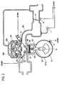
- Fig. 2 is a pictorial view illustrating an intake structure of an engine to which the engine control system of the illustrative embodiment is applied.
- an engine an ECM (Engine Control Module) and peripheral constitutional elements thereof, which are necessary when applying the present invention, are shown so as to simplify the descriptions, and the other constitutional elements are not shown.
- the engine control system according to the illustrative embodiment is applied to an outboard motor having no battery, for example.
- an engine control system 1 includes an engine 2, which is an internal combustion engine, and an ECM 3 configured to control the engine 2.
- the engine 2 is provided with a recoil starter 4 and a generator (AC generator) 5.
- the ECM 3 is connected with an engine rotation number sensor 6, an intake pressure sensor 7, a throttle position sensor 8 and an injector 9. Also, the engine rotation number sensor 6 and the intake pressure sensor 7 configure the rotation number detection means and the pressure detection means defined in the claims, respectively.
- the engine 2 is a direct acting-type DOHC (Double OverHead Camshaft) engine, for example, and has a crankshaft 21, a cylinder 22, a cylinder head 23 and the like (refer to Fig. 2 ).
- DOHC Double OverHead Camshaft
- a piston 24 is accommodated to vertically reciprocate.
- the crankshaft 21 and the piston 24 are coupled by a connecting rod 25.
- the piston 24 reciprocates vertically, so that the crankshaft 21 is rotated through the connecting rod 25.
- a combustion chamber 231 is provided in the cylinder head 23, a combustion chamber 231 is provided.
- An intake valve 26 and an exhaust valve 27 are arranged at the cylinder head 23, in correspondence to an intake port and an exhaust port.
- a pair of rocker arms 28a, 28b is provided in correspondence to the intake valve 26 and the exhaust valve 27.
- the cylinder head 23 is provided with a camshaft 29 configured to drive the rocker arms 28a, 28b.
- a cam chain (not shown) is put on the crankshaft 21 and the camshaft 29, and rotation of the crankshaft 21 is transmitted to the camshaft 29 through the cam chain.
- the cylinder head 23 is provided with an ignition device 30 configured to ignite a mixture gas in the combustion chamber 231.
- the ignition device 30 is configured to ignite at a predetermined timing based on an ignition signal supplied from the ECM 3.
- the recoil starter 4 is configured to function as a manual starting device, and is provided at one end of the crankshaft 21 of the engine 2.
- a pulley (not shown) is accommodated.
- a rope 41 is wound on the pulley with one end being exposed from a case of the recoil starter 4.
- an operator pulls the end portion of the rope 41 with a hand, a rotating force can be applied to the crankshaft 21 of the engine 2.
- the generator 5 is provided at the same end portion of the crankshaft 21 of the engine 2 at which the recoil starter 4 is provided.
- the generator 5 consists of an alternating current magnet generator.
- the alternating current magnet generator includes a permanent magnet provided at the other end of the crankshaft 21 and a power generation coil arranged to face the permanent magnet. As the crankshaft 21 is rotated, the permanent magnet is rotated to generate an electromotive force, so that the power is generated in the power generation coil.
- the ECM 3 includes a calculation means such as a CPU and the like, and a storage means such as a RAM, a ROM and the like.
- the ECM 3 is driven by the power, which is generated from the generator 5 as the engine 2 is driven.
- the CPU executes a program stored in the ROM, so that the ECM 3 functions as an atmospheric pressure estimation unit 31, an atmospheric pressure storage unit 32 and a fuel injection amount calculation unit 33.
- the atmospheric pressure estimation unit 31, the atmospheric pressure storage unit 32 and the fuel injection amount calculation unit 33 configure the atmospheric pressure estimation means, the storage means and the fuel injection amount calculation means defined in the claims, respectively.
- the engine rotation number sensor 6 is arranged to face an outer peripheral edge of a crank magnet 211 configured to integrally rotate with the crankshaft 21, for example (refer to Fig. 2 ).
- the crank magnet 211 has a substantial disc shape and is formed on an outer periphery thereof with a plurality of projections 211a.
- the engine rotation number sensor 6 is configured to detect an engine rotation number based on the number of the projections 211a passing through a detection area as the crankshaft 21 is rotated, for example.
- the engine rotation number detected by the engine rotation number sensor 6 is output to the ECM 3 (more specifically, the atmospheric pressure estimation unit 31 and the fuel injection amount calculation unit 33).
- the intake pressure sensor 7 is arranged at an intake pipe 201 coupled to the intake port (refer to Fig. 2 ).
- the intake pipe 201 is provided with a throttle valve 10.
- the intake pressure sensor 7 is arranged at the intake pipe 201 positioned downstream (left in Fig. 2 ) of the throttle valve 10 and between the intake port and the throttle valve, and is configured to detect a pressure (intake pipe pressure) in the intake pipe 201.
- the intake pipe pressure detected by the intake pressure sensor 7 is output to the ECM 3 (more specifically, the atmospheric pressure estimation unit 31 and the fuel injection amount calculation unit 33).
- the throttle position sensor 8 is arranged at a position of the intake pipe 201 corresponding to the throttle valve 10, for example (refer to Fig. 2 ).
- the throttle position sensor 8 is configured to detect an opening degree (throttle opening degree) of the throttle valve 10.
- the throttle opening degree detected by the throttle position sensor 8 is output to the ECM 3.
- the injector 9 is configured to function as an electronic fuel injection device and is attached to the intake pipe 201 of the engine 2 (refer to Fig. 2 ).
- the injector 9 is configured to inject the fuel, which is supplied from a fuel pump (not shown), into the intake pipe 201, in response to a driving signal from the ECM 3.
- the atmospheric pressure estimation unit 31 is configured to estimate an atmospheric pressure (estimated atmospheric pressure) from the pressure (intake pipe pressure) of the intake pipe 201 detected by the intake pressure sensor 7. More specifically, the atmospheric pressure estimation unit 31 is configured to estimate a maximum intake pipe pressure within a predetermined time period from the start of the engine 2, as the estimated atmospheric pressure.
- the estimated atmospheric pressure estimated by the atmospheric pressure estimation unit 31 is output to the fuel injection amount calculation unit 33, and is also output to the atmospheric pressure storage unit 32 when an update condition of a learning atmospheric pressure (which will be described later) is satisfied.
- the atmospheric pressure storage unit 32 is configured to store therein the estimated atmospheric pressure output from the atmospheric pressure estimation unit 31, as a learning atmospheric pressure.
- the atmospheric pressure storage unit 32 is configured to store the estimated atmospheric pressure as the learning atmospheric pressure, after the engine 2 is stopped.
- the learning atmospheric pressure is used as a comparison target with the estimated atmospheric pressure estimated by the atmospheric pressure estimation unit 31 upon the fuel injection control when the engine 2 is started next time.
- a non-volatile memory such as an electrically erasable programmable read-only memory (EEPROM) and the like is appropriately used.
- the atmospheric pressure storage unit 32 is implemented by the EEPROM, so that it is possible to preserve the estimated atmospheric pressure (learning atmospheric pressure) even after the engine is stopped.
- the fuel injection amount calculation unit 33 is configured to calculate a fuel injection amount of the injector 9.
- the fuel injection amount calculation unit 33 is configured to calculate a fuel injection amount based on the engine rotation number detected by the engine rotation number sensor 6 and the estimated atmospheric pressure estimated by the atmospheric pressure estimation unit 31 or learning atmospheric pressure stored in the atmospheric pressure storage unit 32. More specifically, the fuel injection amount calculation unit 33 is configured to compare the estimated atmospheric pressure estimated by the atmospheric pressure estimation unit 31 and the learning atmospheric pressure stored in the atmospheric pressure storage unit 32, to calculate a fuel injection amount by using the learning atmospheric pressure when a difference thereof is smaller than a predetermined value, and to calculate a fuel injection amount by using the estimated atmospheric pressure estimated based on the intake pipe pressure when the difference is equal to or larger than the predetermined value.
- the fuel injection amount calculation unit 33 converts a control mode (a non-lean burn control, a lean burn control), depending on a calculation result of the fuel injection amount, when a predetermined condition is satisfied. As described in detail later, when the difference between the estimated atmospheric pressure corrected by the atmospheric pressure estimation unit 31 and the learning atmospheric pressure is equal to or smaller than a predetermined value, the fuel injection amount calculation unit shifts from the non-lean burn control mode to the lean burn control mode and adjusts (calculates) the fuel injection amount in conformity to the lean burn control mode.
- a control mode a non-lean burn control, a lean burn control
- the estimated atmospheric pressure estimated by the atmospheric pressure estimation unit 31 and the learning atmospheric pressure stored in the atmospheric pressure storage unit 32 are compared upon the fuel injection control.
- the fuel injection amount is calculated using the estimated atmospheric pressure or learning atmospheric pressure, depending on the comparison result thereof, so that the fuel injection control is appropriately performed, irrespective of situations of the throttle opening degree.
- FIG. 3 is a flowchart for illustrating an operation outline upon the fuel injection control in the engine control system 1 of the illustrative embodiment.
- the fuel injection control is performed with reference to the learning atmospheric pressure stored upon the previous engine stop.
- the fuel injection control of the engine control system 1 includes atmospheric pressure learning processing (step (hereinafter, referred to as 'ST') 301), fuel injection amount calculating processing (injection amount calculating processing: ST302) and fuel injection processing (injection processing: ST303).
- FIG. 3 illustrates that the injection amount calculating processing and the injection processing denoted with ST302 and ST303 are executed after the atmospheric pressure learning processing denoted with ST301 is executed, for convenience of explanations. However, actually, the injection amount calculating processing and the injection processing denoted with ST302 and ST303 are executed in parallel with the atmospheric pressure learning processing denoted with ST301.
- the atmospheric pressure learning processing is processing of learning a learning atmospheric pressure that is to be referred to upon the fuel injection control.
- the learning atmospheric pressure is learned (updated) when a predetermined update condition is satisfied.
- the learning atmospheric pressure at that time is stored in the atmospheric pressure storage unit 32.
- the injection amount calculating processing is executed in parallel with the atmospheric pressure learning processing (ST302).
- the injection amount calculating processing is processing of calculating a fuel injection amount of the injector 9 based on a difference between the learning atmospheric pressure stored in the atmospheric pressure storage unit 32 and the estimated atmospheric pressure (the estimated atmospheric pressure based on the intake pipe pressure detected by the intake pressure sensor 7) estimated by the atmospheric pressure estimation unit 31.
- the fuel injection amount is calculated and it is also determined whether the control mode is converted (shifted). Based on a result of the determination, the fuel injection amount is adjusted. More specifically, when a difference between the estimated atmospheric pressure corrected by the atmospheric pressure estimation unit 31 and the learning atmospheric pressure is equal to or smaller than a predetermined value, the control mode is converted from the non-lean burn control mode to the lean burn control mode and the fuel injection amount is adjusted in conformity to the lean burn control mode.
- the injection processing is executed (ST303).
- the injection processing the fuel is injected from the injector 9 based on the fuel injection amount calculated in the injection amount calculating processing.
- the injection amount calculating processing and the injection processing denoted with ST302 and ST303 are repeatedly executed during the operation of the engine 2.
- Fig. 4 is a flowchart for illustrating the atmospheric pressure learning processing in the engine control system 1 of the illustrative embodiment.
- the pressure (intake pipe pressure) in the intake pipe 201 is first detected by the intake pressure sensor 7 (ST401).
- the detected intake pipe pressure is output to the atmospheric pressure estimation unit 31 of the ECM 3.
- the atmospheric pressure estimation unit 31 estimates a maximum intake pipe pressure within a predetermined time period from the start of the engine 2, as a current atmospheric pressure, and obtains the estimated atmospheric pressure (ST402).
- the fuel injection amount calculation unit 33 reads out the learning atmospheric pressure stored in the atmospheric pressure storage unit 32 (more specifically, the learning atmospheric pressure stored in the atmospheric pressure storage unit 32 upon the previous operation stop) (ST403). Then, the fuel injection amount calculation unit 33 determines whether a difference between the estimated atmospheric pressure estimated in ST402 and the learning atmospheric pressure stored upon the previous operation stop is equal to or larger than a predetermined atmospheric pressure update determining value (hereinafter, simply referred to as 'determining value') (ST404).
- 'determining value' a predetermined atmospheric pressure update determining value
- the throttle position sensor 8 determines whether the throttle opening degree is at a complete opening state (WOT: Wide Open Throttle) continuously for a predetermined time period (ST405).
- WOT Wide Open Throttle
- '1' is set for a flag (hereinafter, referred to as 'learning execution flag') indicating whether or not to execute the learning of the learning atmospheric pressure (ST406).
- '1' is set for the learning execution flag, so that it is permitted to learn (update) the learning atmospheric pressure by using the estimated atmospheric pressure estimated in ST402.
- the estimated atmospheric pressure estimated in ST402 is recorded in the atmospheric pressure storage unit 32.
- ST404 and ST405 are processing of determining the update condition of the learning atmospheric pressure. When all results of the determinations are positive, the update condition of the learning atmospheric pressure is satisfied. Also, when the WOT state is not or when the WOT state does not continue for a predetermined time period, the determination of ST405 is repeated.
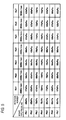
- the atmospheric pressure estimation unit 31 can adjust the estimated atmospheric pressure based on an estimated atmospheric pressure adjusting map shown in Fig. 5.
- Fig. 5 shows an example of the estimated atmospheric pressure adjusting map that is used in the engine control system 1 of the illustrative embodiment.
- a detection value Pb by the intake pressure sensor 7 corresponds to a vertical axis
- an engine rotation number Ne by the engine rotation number sensor 6 corresponds to a horizontal axis.
- the atmospheric pressure estimation unit 31 can adjust the same based on the estimated atmospheric pressure adjusting map shown in Fig. 5 , depending on the engine rotation number received from the engine rotation number sensor 6.
- the atmospheric pressure estimation unit 31 can adjust the estimated atmospheric pressure to '68 kPa' (refer to Pb4 and Ne2 in Fig. 5 ). Also, in a case where '80 kPa' is received from the intake pressure sensor 7, as the intake pipe pressure, when the engine rotation number received from the engine rotation number sensor 6 is '5000 r/min', the atmospheric pressure estimation unit 31 can adjust the estimated atmospheric pressure to '83 kPa' (refer to Pb5 and Ne7 in Fig. 5 ).
- the atmospheric pressure estimation unit 31 adjusts the estimated atmospheric pressure, depending on the engine rotation number, so that it is possible to adjust the estimated atmospheric pressure in conformity to the intake pipe pressure varying depending on the engine rotation number. Thereby, it is possible to obtain the estimated atmospheric pressure within a more correct and wider range, in conformity to the intake pipe pressure varying depending on the engine rotation number.
- the atmospheric pressure estimation unit 31 executes correction processing of the estimated atmospheric pressure (estimated atmospheric pressure correcting processing) (ST407).
- the estimated atmospheric pressure correcting processing the estimated atmospheric pressure (estimated atmospheric pressure estimated in ST402) is corrected based on a predetermined atmospheric pressure learning filter value and the learning atmospheric pressure.
- a corrected estimated atmospheric pressure X that is to be corrected by the estimated atmospheric pressure correcting processing is calculated based on the following (Equation 1).
- 'F1' indicates the atmospheric pressure learning filter value.
- X F ⁇ 1 ⁇ learning atmospheric pressure + 1 - F ⁇ 1 ⁇ estimated atmospheric pressure
- the fuel injection amount calculation unit 33 determines whether a difference between the estimated atmospheric pressure after the correction (corrected estimated atmospheric pressure) and the current estimated atmospheric pressure estimated from the intake pipe pressure is equal to or smaller than the determining value (ST408). When the difference between the corrected estimated atmospheric pressure and the current estimated atmospheric pressure is not equal to or smaller than the determining value, the processing returns to ST405 and the processing of ST405 to ST408 is again executed.
- '1' is set for a flag (hereinafter, referred to as 'mode conversion flag') indicating whether or not to permit the conversion to the lean burn control mode (ST409).
- '1' is set for the mode conversion flag in this way, so that the conversion from the non-lean burn control mode to the lean burn control mode is permitted. That is, the shift to the lean burn control mode is permitted only when the difference between the corrected estimated atmospheric pressure and the current estimated atmospheric pressure is equal to or smaller than the determining value.
- the processing of ST409 and thereafter is executed. That is, after '1' is set for the mode conversion flag in ST409, it is determined in ST410 whether the ignition switch is on or not, and when the ignition switch is off, the learning atmospheric pressure is updated in ST411. After the learning atmospheric pressure is updated in ST411 via the series of processing, the atmospheric pressure learning processing is over.
- Fig. 6 is a flowchart for illustrating the injection amount calculating processing in the engine control system of the illustrative embodiment.
- the pressure (intake pipe pressure) in the intake pipe 201 is first detected by the intake pressure sensor 7 (ST601).
- the detected intake pipe pressure is output to the atmospheric pressure estimation unit 31 of the ECM 3.
- the atmospheric pressure estimation unit 31 estimates a maximum intake pipe pressure within a predetermined time period from the start of the engine 2, as a current atmospheric pressure, and obtains the estimated atmospheric pressure (ST602).
- the fuel injection amount calculation unit 33 reads out the learning atmospheric pressure stored in the atmospheric pressure storage unit 32 (ST603). Then, the fuel injection amount calculation unit 33 determines whether a difference between the estimated atmospheric pressure estimated in ST402 and the learning atmospheric pressure is equal to or larger than the determining value (atmospheric pressure update determining value) (ST604).
- the fuel injection amount calculation unit 33 calculates a fuel injection amount by using the estimated atmospheric pressure estimated in ST602 (ST605).
- the fuel injection amount calculation unit 33 calculates a fuel injection amount by using the learning atmospheric pressure stored in the atmospheric pressure storage unit 32 (ST606).
- the fuel injection amount calculation unit 33 determines whether '1' is set for the mode conversion flag (ST607). This determination is to determine whether the shift from the non-lean burn control mode to the lean burn control mode is permitted.
- the fuel injection amount calculation unit 33 adjusts the fuel injection amount calculated in ST606 to a fuel injection amount appropriate to the lean burn control mode (ST608). That is, the fuel injection amount is adjusted so that an air-fuel ratio of which a fuel ratio is smaller than an ideal air-fuel ratio by the non-lean burn control mode is made.
- the fuel injection amount calculation unit 33 skips over ST608 and does not adjust the fuel injection amount to a fuel injection amount appropriate to the lean burn control mode.
- the injection amount calculating processing is over.
- the fuel injection amount calculated (adjusted) in the injection amount calculating processing is used in the injection processing denoted with ST303 in Fig. 3 , and the fuel corresponding to the fuel injection amount is injected to the intake pipe 201 from the injector 9.
- the fuel injection amount calculated based on any one of the estimated atmospheric pressure based on the intake pipe pressure and the learning atmospheric pressure stored in the atmospheric pressure storage unit 32 is injected.
- the estimated atmospheric pressure estimated upon the engine start and the learning atmospheric pressure stored in the atmospheric pressure storage unit 32 are compared.
- the difference thereof is smaller than the predetermined value (determining value)
- the fuel injection amount is calculated using the learning atmospheric pressure.
- the difference is equal to or larger than the predetermined value (determining value)
- the fuel injection amount is calculated using the estimated atmospheric pressure estimated from the intake pipe pressure. For this reason, even when the throttle opening degree does not reach a vicinity of the complete opening, for example, it is possible to calculate the fuel injection amount by using the stored learning atmospheric pressure. As a result, it is possible to appropriately control the fuel injection, irrespective of the situations of the throttle opening degree.
- the fuel injection amount calculation unit 33 calculates the fuel injection amount appropriate to the lean burn control from the non-lean burn control when the difference between the estimated atmospheric pressure and the learning atmospheric pressure is equal to or smaller than the predetermined value (determining value). Therefore, since the fuel injection amount appropriate to the lean burn control is calculated only when the difference between the estimated atmospheric pressure and the learning atmospheric pressure is equal to or smaller than the predetermined value, it is possible to realize the lean burn operation while preventing the engine output from being rapidly lowered.
- the present invention is not limited to the above illustrative embodiment and can be variously changed.
- the circuit configuration, the control flow and the like are not limited to the accompanying drawings and can be appropriately changed within the scope in which the effects of the present invention are accomplished.
- the illustrative embodiment can be appropriately changed and implemented without departing from the scope of the present invention.
- the learning atmospheric pressure is updated all the time in the atmospheric pressure storage unit 32 upon the engine stop.
- the timing at which the learning atmospheric pressure is always updated is not limited to upon the engine stop, and can be appropriately changed.
- the learning atmospheric pressure may be updated.
- the present invention can accomplish the effect of appropriately controlling the fuel injection, irrespective of the situations of the throttle opening degree, and is particularly useful for an outboard motor, an automatic two-wheeled vehicle and the like in which a battery is not provided and an engine configured to drive a fuel injection device configured to adjust a fuel injection amount with the power generated from a generator is mounted thereto.
Landscapes
- Engineering & Computer Science (AREA)
- Chemical & Material Sciences (AREA)
- Combustion & Propulsion (AREA)
- Mechanical Engineering (AREA)
- General Engineering & Computer Science (AREA)
- Computer Hardware Design (AREA)
- Microelectronics & Electronic Packaging (AREA)
- Combined Controls Of Internal Combustion Engines (AREA)
- Electrical Control Of Air Or Fuel Supplied To Internal-Combustion Engine (AREA)
Abstract
Description
- The invention relates to an engine control system, and more particularly, to an engine control system configured to control an engine having a fuel injection (FI) device configured to adjust a fuel injection amount.
- In a fuel injection (FI) device configured to estimate an intake amount by using an intake pressure sensor, since an air density is used to control the fuel injection, atmospheric pressure detection is necessarily required. In general, a large-scaled outboard motor having an engine mounted thereto, on which the FI device is mounted, has a battery. For this reason, the intake pressure sensor for atmospheric pressure detection can be fed with power from the battery just after an ignition switch is switched to an on state, so that it can correctly detect an atmospheric pressure.
- In recent years, a small-scaled outboard motor having an engine mounted thereto, on which the FI device is mounted, is also widely used. Also in the small-scaled outboard motor, the atmospheric pressure detection is required so as to appropriately control the fuel injection. However, in some small-scaled outboard motors, a battery is not provided and the engine load is driven only with self-power generation by a generator (AC generator). In these small-scaled outboard motors, the atmospheric pressure is estimated with the intake pressure sensor after the engine is started.
- For example, a control system has been suggested in which a maximum intake pressure upon the engine start is used as an estimated atmospheric pressure, and when an intake pressure (detected intake pressure) detected at a timing at which a throttle opening degree reaches a vicinity of a complete opening is higher than the estimated atmospheric pressure at that time, the detected intake pressure is updated as the estimated atmospheric pressure (for example, refer to Patent Document 1). In this control system, since the intake pressure detected upon the complete opening of the throttle is updated as the estimated atmospheric pressure, it is possible to detect the estimated atmospheric pressure, depending on operating situations of the engine.
- [Patent Document 1]
Japanese Patent Application Publication No. 2013-199915A - However, according to the control system of
Patent Document 1, the estimated atmospheric pressure is updated at the timing at which the throttle opening degree reaches the vicinity of the complete opening. For this reason, when the throttle opening degree does not reach the vicinity of the complete opening, a difference between the maximum intake pressure upon the engine start and the actual atmospheric pressure may increase. In this case, the fuel injection is controlled based on the estimated atmospheric pressure having a difference from the actual atmospheric pressure, so that it is difficult to appropriately control the fuel injection. - It is therefore an object of the present invention to provide an engine control system capable of appropriately controlling fuel injection, irrespective of situations of a throttle opening degree.
- An engine control system of the present invention includes a rotation number detection means for detecting an engine rotation number; a pressure detection means for detecting an intake pipe pressure downstream of a throttle valve; an atmospheric pressure estimation means for estimating an estimated atmospheric pressure from the intake pipe pressure detected by the pressure detection means; a storage means for storing the estimated atmospheric pressure output from the atmospheric pressure estimation means, as a learning atmospheric pressure, after an engine is stopped; and a fuel injection amount calculation means for calculating a fuel injection amount based on the engine rotation number and the estimated atmospheric pressure, wherein the fuel injection amount calculation means is configured to compare the estimated atmospheric pressure estimated upon engine start and the learning atmospheric pressure stored in the storage means, and calculates a fuel injection amount by using the learning atmospheric pressure when a difference between the estimated atmospheric pressure and the learning atmospheric pressure is smaller than a predetermined value and calculates a fuel injection amount by using the estimated atmospheric pressure when the difference between the estimated atmospheric pressure and the learning atmospheric pressure is equal to or larger than the predetermined value.
- According to the above configuration, the estimated atmospheric pressure estimated upon the engine start and the learning atmospheric pressure stored in the storage means are compared. When a difference thereof is smaller than the predetermined value, the fuel injection amount is calculated using the learning atmospheric pressure stored in the storage means. For this reason, even when the throttle opening degree does not reach a vicinity of the complete opening, for example, it is possible to calculate the fuel injection amount by using the stored learning atmospheric pressure. As a result, it is possible to appropriately control the fuel injection, irrespective of the situations of the throttle opening degree.
- In the engine control system, when the difference between the estimated atmospheric pressure and the learning atmospheric pressure is equal to or larger than the predetermined value, the atmospheric pressure estimation means preferably adjusts the estimated atmospheric pressure, depending on the engine rotation number. In this case, since it is possible to adjust the estimated atmospheric pressure in conformity to the intake pressure varying depending on the engine rotation number, it is possible to update the estimated atmospheric pressure within a more correct and wider range.
- Also, in the engine control system, when the difference between the estimated atmospheric pressure and the learning atmospheric pressure is equal to or smaller than the predetermined value, the fuel injection amount calculation means preferably calculates a fuel injection amount appropriate to a lean burn control from a non-lean burn control. In this case, since the fuel injection amount appropriate to the lean burn control is calculated only when the difference between the estimated atmospheric pressure estimated from the intake pipe pressure and the learning atmospheric pressure is equal to or smaller than the predetermined value, it is possible to realize the shift to the lean burn control while preventing the engine output from being rapidly lowered.
- According to the engine control system of the present invention, it is possible to appropriately control the fuel injection, irrespective of situations of the throttle opening degree.
-
-
Fig. 1 shows a schematic configuration of an engine control system according to an illustrative embodiment. -
Fig. 2 is a pictorial view illustrating an intake structure of an engine to which the engine control system of the illustrative embodiment is applied. -
Fig. 3 is a flowchart for illustrating an operation outline upon fuel injection control in the engine control system of the illustrative embodiment. -
Fig. 4 is a flowchart for illustrating atmospheric pressure learning processing in the engine control system of the illustrative embodiment. -
Fig. 5 shows an example of an estimated atmospheric pressure adjusting map that is used in the engine control system of the illustrative embodiment. -
Fig. 6 is a flowchart for illustrating injection amount calculating processing in the engine control system of the illustrative embodiment. - Hereinafter, an illustrative embodiment will be described in detail with reference to the accompanying drawings. In below descriptions, a case where the engine control system of the present invention is applied to an outboard motor will be described. However, the application target is not limited to the outboard motor and can be appropriately changed. For example, the present invention can also be applied to a vehicle such as an automatic two-wheeled vehicle having a configuration of estimating an atmospheric pressure by an intake pressure sensor. Also, the engine control system of the present invention is appropriately used for an outboard motor having no battery. However, the present invention can also be applied to an outboard motor having a battery mounted thereto.
-
Fig. 1 shows a schematic configuration of an engine control system according to an illustrative embodiment.Fig. 2 is a pictorial view illustrating an intake structure of an engine to which the engine control system of the illustrative embodiment is applied. InFig. 1 , only an engine, an ECM (Engine Control Module) and peripheral constitutional elements thereof, which are necessary when applying the present invention, are shown so as to simplify the descriptions, and the other constitutional elements are not shown. The engine control system according to the illustrative embodiment is applied to an outboard motor having no battery, for example. - As shown in
Fig. 1 , anengine control system 1 includes anengine 2, which is an internal combustion engine, and anECM 3 configured to control theengine 2. Theengine 2 is provided with arecoil starter 4 and a generator (AC generator) 5. TheECM 3 is connected with an enginerotation number sensor 6, anintake pressure sensor 7, athrottle position sensor 8 and aninjector 9. Also, the enginerotation number sensor 6 and theintake pressure sensor 7 configure the rotation number detection means and the pressure detection means defined in the claims, respectively. - The
engine 2 is a direct acting-type DOHC (Double OverHead Camshaft) engine, for example, and has acrankshaft 21, a cylinder 22, acylinder head 23 and the like (refer toFig. 2 ). In the cylinder 22, apiston 24 is accommodated to vertically reciprocate. Thecrankshaft 21 and thepiston 24 are coupled by a connectingrod 25. Thepiston 24 reciprocates vertically, so that thecrankshaft 21 is rotated through the connectingrod 25. - In the
cylinder head 23, acombustion chamber 231 is provided. Anintake valve 26 and anexhaust valve 27 are arranged at thecylinder head 23, in correspondence to an intake port and an exhaust port. A pair ofrocker arms intake valve 26 and theexhaust valve 27. Also, thecylinder head 23 is provided with acamshaft 29 configured to drive therocker arms crankshaft 21 and thecamshaft 29, and rotation of thecrankshaft 21 is transmitted to thecamshaft 29 through the cam chain. - When the
camshaft 29 is rotated, the pair ofrocker arms intake valve 26 and theexhaust valve 27 are reciprocally moved towards thecombustion chamber 231. In this way, opening and closing timings of therespective intake valve 26 andexhaust valve 27 are adjusted. Also, thecylinder head 23 is provided with anignition device 30 configured to ignite a mixture gas in thecombustion chamber 231. Theignition device 30 is configured to ignite at a predetermined timing based on an ignition signal supplied from theECM 3. - The
recoil starter 4 is configured to function as a manual starting device, and is provided at one end of thecrankshaft 21 of theengine 2. In therecoil starter 4, a pulley (not shown) is accommodated. Arope 41 is wound on the pulley with one end being exposed from a case of therecoil starter 4. When an operator (driver) pulls the end portion of therope 41 with a hand, a rotating force can be applied to thecrankshaft 21 of theengine 2. - The
generator 5 is provided at the same end portion of thecrankshaft 21 of theengine 2 at which therecoil starter 4 is provided. For example, thegenerator 5 consists of an alternating current magnet generator. The alternating current magnet generator includes a permanent magnet provided at the other end of thecrankshaft 21 and a power generation coil arranged to face the permanent magnet. As thecrankshaft 21 is rotated, the permanent magnet is rotated to generate an electromotive force, so that the power is generated in the power generation coil. - The
ECM 3 includes a calculation means such as a CPU and the like, and a storage means such as a RAM, a ROM and the like. TheECM 3 is driven by the power, which is generated from thegenerator 5 as theengine 2 is driven. For example, the CPU executes a program stored in the ROM, so that theECM 3 functions as an atmosphericpressure estimation unit 31, an atmosphericpressure storage unit 32 and a fuel injectionamount calculation unit 33. These constitutional elements will be described in detail later. Also, the atmosphericpressure estimation unit 31, the atmosphericpressure storage unit 32 and the fuel injectionamount calculation unit 33 configure the atmospheric pressure estimation means, the storage means and the fuel injection amount calculation means defined in the claims, respectively. - The engine
rotation number sensor 6 is arranged to face an outer peripheral edge of acrank magnet 211 configured to integrally rotate with thecrankshaft 21, for example (refer toFig. 2 ). Thecrank magnet 211 has a substantial disc shape and is formed on an outer periphery thereof with a plurality ofprojections 211a. The enginerotation number sensor 6 is configured to detect an engine rotation number based on the number of theprojections 211a passing through a detection area as thecrankshaft 21 is rotated, for example. The engine rotation number detected by the enginerotation number sensor 6 is output to the ECM 3 (more specifically, the atmosphericpressure estimation unit 31 and the fuel injection amount calculation unit 33). - The
intake pressure sensor 7 is arranged at anintake pipe 201 coupled to the intake port (refer toFig. 2 ). Theintake pipe 201 is provided with athrottle valve 10. Theintake pressure sensor 7 is arranged at theintake pipe 201 positioned downstream (left inFig. 2 ) of thethrottle valve 10 and between the intake port and the throttle valve, and is configured to detect a pressure (intake pipe pressure) in theintake pipe 201. The intake pipe pressure detected by theintake pressure sensor 7 is output to the ECM 3 (more specifically, the atmosphericpressure estimation unit 31 and the fuel injection amount calculation unit 33). - The
throttle position sensor 8 is arranged at a position of theintake pipe 201 corresponding to thethrottle valve 10, for example (refer toFig. 2 ). Thethrottle position sensor 8 is configured to detect an opening degree (throttle opening degree) of thethrottle valve 10. The throttle opening degree detected by thethrottle position sensor 8 is output to theECM 3. - The
injector 9 is configured to function as an electronic fuel injection device and is attached to theintake pipe 201 of the engine 2 (refer toFig. 2 ). Theinjector 9 is configured to inject the fuel, which is supplied from a fuel pump (not shown), into theintake pipe 201, in response to a driving signal from theECM 3. - The atmospheric
pressure estimation unit 31 is configured to estimate an atmospheric pressure (estimated atmospheric pressure) from the pressure (intake pipe pressure) of theintake pipe 201 detected by theintake pressure sensor 7. More specifically, the atmosphericpressure estimation unit 31 is configured to estimate a maximum intake pipe pressure within a predetermined time period from the start of theengine 2, as the estimated atmospheric pressure. The estimated atmospheric pressure estimated by the atmosphericpressure estimation unit 31 is output to the fuel injectionamount calculation unit 33, and is also output to the atmosphericpressure storage unit 32 when an update condition of a learning atmospheric pressure (which will be described later) is satisfied. - The atmospheric
pressure storage unit 32 is configured to store therein the estimated atmospheric pressure output from the atmosphericpressure estimation unit 31, as a learning atmospheric pressure. In particular, the atmosphericpressure storage unit 32 is configured to store the estimated atmospheric pressure as the learning atmospheric pressure, after theengine 2 is stopped. The learning atmospheric pressure is used as a comparison target with the estimated atmospheric pressure estimated by the atmosphericpressure estimation unit 31 upon the fuel injection control when theengine 2 is started next time. As the storage means configuring the atmosphericpressure storage unit 32, a non-volatile memory such as an electrically erasable programmable read-only memory (EEPROM) and the like is appropriately used. The atmosphericpressure storage unit 32 is implemented by the EEPROM, so that it is possible to preserve the estimated atmospheric pressure (learning atmospheric pressure) even after the engine is stopped. - The fuel injection
amount calculation unit 33 is configured to calculate a fuel injection amount of theinjector 9. The fuel injectionamount calculation unit 33 is configured to calculate a fuel injection amount based on the engine rotation number detected by the enginerotation number sensor 6 and the estimated atmospheric pressure estimated by the atmosphericpressure estimation unit 31 or learning atmospheric pressure stored in the atmosphericpressure storage unit 32. More specifically, the fuel injectionamount calculation unit 33 is configured to compare the estimated atmospheric pressure estimated by the atmosphericpressure estimation unit 31 and the learning atmospheric pressure stored in the atmosphericpressure storage unit 32, to calculate a fuel injection amount by using the learning atmospheric pressure when a difference thereof is smaller than a predetermined value, and to calculate a fuel injection amount by using the estimated atmospheric pressure estimated based on the intake pipe pressure when the difference is equal to or larger than the predetermined value. - Also, the fuel injection
amount calculation unit 33 converts a control mode (a non-lean burn control, a lean burn control), depending on a calculation result of the fuel injection amount, when a predetermined condition is satisfied. As described in detail later, when the difference between the estimated atmospheric pressure corrected by the atmosphericpressure estimation unit 31 and the learning atmospheric pressure is equal to or smaller than a predetermined value, the fuel injection amount calculation unit shifts from the non-lean burn control mode to the lean burn control mode and adjusts (calculates) the fuel injection amount in conformity to the lean burn control mode. - In the
engine control system 1 having the above configuration according to the illustrative embodiment, the estimated atmospheric pressure estimated by the atmosphericpressure estimation unit 31 and the learning atmospheric pressure stored in the atmosphericpressure storage unit 32 are compared upon the fuel injection control. The fuel injection amount is calculated using the estimated atmospheric pressure or learning atmospheric pressure, depending on the comparison result thereof, so that the fuel injection control is appropriately performed, irrespective of situations of the throttle opening degree. - Here, operations that are performed upon the fuel injection control in the
engine control system 1 according to the illustrative embodiment are described.Fig. 3 is a flowchart for illustrating an operation outline upon the fuel injection control in theengine control system 1 of the illustrative embodiment. - In the
engine control system 1 of the illustrative embodiment, the fuel injection control is performed with reference to the learning atmospheric pressure stored upon the previous engine stop. To this end, as shown inFig. 3 , the fuel injection control of theengine control system 1 includes atmospheric pressure learning processing (step (hereinafter, referred to as 'ST') 301), fuel injection amount calculating processing (injection amount calculating processing: ST302) and fuel injection processing (injection processing: ST303). - Also,
Fig. 3 illustrates that the injection amount calculating processing and the injection processing denoted with ST302 and ST303 are executed after the atmospheric pressure learning processing denoted with ST301 is executed, for convenience of explanations. However, actually, the injection amount calculating processing and the injection processing denoted with ST302 and ST303 are executed in parallel with the atmospheric pressure learning processing denoted with ST301. - In the
engine control system 1, while theengine 2 is operating, the atmospheric pressure learning processing is executed (S301). The atmospheric pressure learning processing is processing of learning a learning atmospheric pressure that is to be referred to upon the fuel injection control. In the atmospheric pressure learning processing, the learning atmospheric pressure is learned (updated) when a predetermined update condition is satisfied. When theengine 2 is stopped, the learning atmospheric pressure at that time is stored in the atmosphericpressure storage unit 32. - The injection amount calculating processing is executed in parallel with the atmospheric pressure learning processing (ST302). The injection amount calculating processing is processing of calculating a fuel injection amount of the
injector 9 based on a difference between the learning atmospheric pressure stored in the atmosphericpressure storage unit 32 and the estimated atmospheric pressure (the estimated atmospheric pressure based on the intake pipe pressure detected by the intake pressure sensor 7) estimated by the atmosphericpressure estimation unit 31. - Also, in the injection amount calculating processing, the fuel injection amount is calculated and it is also determined whether the control mode is converted (shifted). Based on a result of the determination, the fuel injection amount is adjusted. More specifically, when a difference between the estimated atmospheric pressure corrected by the atmospheric
pressure estimation unit 31 and the learning atmospheric pressure is equal to or smaller than a predetermined value, the control mode is converted from the non-lean burn control mode to the lean burn control mode and the fuel injection amount is adjusted in conformity to the lean burn control mode. - After the fuel injection amount is calculated by the injection amount calculating processing, the injection processing is executed (ST303). In the injection processing, the fuel is injected from the
injector 9 based on the fuel injection amount calculated in the injection amount calculating processing. The injection amount calculating processing and the injection processing denoted with ST302 and ST303 are repeatedly executed during the operation of theengine 2. - Here, the atmospheric pressure learning processing denoted with ST301 is described in detail.
Fig. 4 is a flowchart for illustrating the atmospheric pressure learning processing in theengine control system 1 of the illustrative embodiment. As shown inFig. 4 , in the atmospheric pressure learning processing, the pressure (intake pipe pressure) in theintake pipe 201 is first detected by the intake pressure sensor 7 (ST401). The detected intake pipe pressure is output to the atmosphericpressure estimation unit 31 of theECM 3. When the intake pipe pressure is received from theintake pressure sensor 7, the atmosphericpressure estimation unit 31 estimates a maximum intake pipe pressure within a predetermined time period from the start of theengine 2, as a current atmospheric pressure, and obtains the estimated atmospheric pressure (ST402). - When the estimated atmospheric pressure is estimated by the atmospheric
pressure estimation unit 31 in ST402 ofFig. 4 , the fuel injectionamount calculation unit 33 reads out the learning atmospheric pressure stored in the atmospheric pressure storage unit 32 (more specifically, the learning atmospheric pressure stored in the atmosphericpressure storage unit 32 upon the previous operation stop) (ST403). Then, the fuel injectionamount calculation unit 33 determines whether a difference between the estimated atmospheric pressure estimated in ST402 and the learning atmospheric pressure stored upon the previous operation stop is equal to or larger than a predetermined atmospheric pressure update determining value (hereinafter, simply referred to as 'determining value') (ST404). - Here, when the difference between the estimated atmospheric pressure and the learning atmospheric pressure is equal to or larger than the predetermined determining value, it is determined by the
throttle position sensor 8 whether the throttle opening degree is at a complete opening state (WOT: Wide Open Throttle) continuously for a predetermined time period (ST405). Here, when the WOT state continues for a predetermined time period, '1' is set for a flag (hereinafter, referred to as 'learning execution flag') indicating whether or not to execute the learning of the learning atmospheric pressure (ST406). '1' is set for the learning execution flag, so that it is permitted to learn (update) the learning atmospheric pressure by using the estimated atmospheric pressure estimated in ST402. In this case, the estimated atmospheric pressure estimated in ST402 is recorded in the atmosphericpressure storage unit 32. ST404 and ST405 are processing of determining the update condition of the learning atmospheric pressure. When all results of the determinations are positive, the update condition of the learning atmospheric pressure is satisfied. Also, when the WOT state is not or when the WOT state does not continue for a predetermined time period, the determination of ST405 is repeated. - When repeating the determination of ST405 in this way, it is preferably to adjust the estimated atmospheric pressure in the atmospheric
pressure estimation unit 31, depending on the engine rotation number, as an illustrative embodiment. In this case, the atmosphericpressure estimation unit 31 can adjust the estimated atmospheric pressure based on an estimated atmospheric pressure adjusting map shown inFig. 5. Fig. 5 shows an example of the estimated atmospheric pressure adjusting map that is used in theengine control system 1 of the illustrative embodiment. - As shown in
Fig. 5 , in the estimated atmospheric pressure adjusting map, a detection value Pb by theintake pressure sensor 7 corresponds to a vertical axis, and an engine rotation number Ne by the enginerotation number sensor 6 corresponds to a horizontal axis. When the intake pipe pressure is received from theintake pressure sensor 7, the atmosphericpressure estimation unit 31 can adjust the same based on the estimated atmospheric pressure adjusting map shown inFig. 5 , depending on the engine rotation number received from the enginerotation number sensor 6. - For example, in a case where '70 kPa' is received from the
intake pressure sensor 7, as the intake pipe pressure, when the engine rotation number received from the enginerotation number sensor 6 is '2500 r/min', the atmosphericpressure estimation unit 31 can adjust the estimated atmospheric pressure to '68 kPa' (refer to Pb4 and Ne2 inFig. 5 ). Also, in a case where '80 kPa' is received from theintake pressure sensor 7, as the intake pipe pressure, when the engine rotation number received from the enginerotation number sensor 6 is '5000 r/min', the atmosphericpressure estimation unit 31 can adjust the estimated atmospheric pressure to '83 kPa' (refer to Pb5 and Ne7 inFig. 5 ). - In this way, when the difference between the estimated atmospheric pressure and the learning atmospheric pressure is equal to or larger than the predetermined value, the atmospheric
pressure estimation unit 31 adjusts the estimated atmospheric pressure, depending on the engine rotation number, so that it is possible to adjust the estimated atmospheric pressure in conformity to the intake pipe pressure varying depending on the engine rotation number. Thereby, it is possible to obtain the estimated atmospheric pressure within a more correct and wider range, in conformity to the intake pipe pressure varying depending on the engine rotation number. - After '1' is set for the learning execution flag in ST406, the atmospheric
pressure estimation unit 31 executes correction processing of the estimated atmospheric pressure (estimated atmospheric pressure correcting processing) (ST407). In the estimated atmospheric pressure correcting processing, the estimated atmospheric pressure (estimated atmospheric pressure estimated in ST402) is corrected based on a predetermined atmospheric pressure learning filter value and the learning atmospheric pressure. For example, a corrected estimated atmospheric pressure X that is to be corrected by the estimated atmospheric pressure correcting processing is calculated based on the following (Equation 1). Here, 'F1' indicates the atmospheric pressure learning filter value.
- After the estimated atmospheric pressure correcting processing is executed, the fuel injection
amount calculation unit 33 determines whether a difference between the estimated atmospheric pressure after the correction (corrected estimated atmospheric pressure) and the current estimated atmospheric pressure estimated from the intake pipe pressure is equal to or smaller than the determining value (ST408). When the difference between the corrected estimated atmospheric pressure and the current estimated atmospheric pressure is not equal to or smaller than the determining value, the processing returns to ST405 and the processing of ST405 to ST408 is again executed. - In contrast, when the difference between the corrected estimated atmospheric pressure and the current estimated atmospheric pressure is equal to or smaller than the determining value, '1' is set for a flag (hereinafter, referred to as 'mode conversion flag') indicating whether or not to permit the conversion to the lean burn control mode (ST409). '1' is set for the mode conversion flag in this way, so that the conversion from the non-lean burn control mode to the lean burn control mode is permitted. That is, the shift to the lean burn control mode is permitted only when the difference between the corrected estimated atmospheric pressure and the current estimated atmospheric pressure is equal to or smaller than the determining value.
- After '1' is set for the mode conversion flag, it is determined whether the ignition switch is kept at the on state (power supply on) (ST410). When the ignition switch is kept at the on state, the processing returns to ST401 and the processing of ST401 to ST410 is again executed. That is, when the power supply on state is kept, the estimated atmospheric pressure based on the intake pipe pressure detected by the
intake pressure sensor 7 and the learning atmospheric pressure are compared and the learning atmospheric pressure is learned depending on the comparison result. On the other hand, when the ignition switch is switched to an off state, the estimated atmospheric pressure estimated in ST402 just before is again recorded in the atmosphericpressure storage unit 32, as the learning atmospheric pressure, so that the learning atmospheric pressure is updated (ST411). - On the other hand, when it is determined in the determination of ST404 that the difference between the estimated atmospheric pressure and the learning atmospheric pressure is smaller than the determining value (atmospheric pressure update determining value), the processing of ST409 and thereafter is executed. That is, after '1' is set for the mode conversion flag in ST409, it is determined in ST410 whether the ignition switch is on or not, and when the ignition switch is off, the learning atmospheric pressure is updated in ST411. After the learning atmospheric pressure is updated in ST411 via the series of processing, the atmospheric pressure learning processing is over.
- Subsequently, the injection amount calculating processing denoted with ST302 is described.
Fig. 6 is a flowchart for illustrating the injection amount calculating processing in the engine control system of the illustrative embodiment. As shown inFig. 6 , in the injection amount calculating processing, the pressure (intake pipe pressure) in theintake pipe 201 is first detected by the intake pressure sensor 7 (ST601). The detected intake pipe pressure is output to the atmosphericpressure estimation unit 31 of theECM 3. When the intake pipe pressure is received from theintake pressure sensor 7, the atmosphericpressure estimation unit 31 estimates a maximum intake pipe pressure within a predetermined time period from the start of theengine 2, as a current atmospheric pressure, and obtains the estimated atmospheric pressure (ST602). - When the estimated atmospheric pressure is estimated by the atmospheric
pressure estimation unit 31, the fuel injectionamount calculation unit 33 reads out the learning atmospheric pressure stored in the atmospheric pressure storage unit 32 (ST603). Then, the fuel injectionamount calculation unit 33 determines whether a difference between the estimated atmospheric pressure estimated in ST402 and the learning atmospheric pressure is equal to or larger than the determining value (atmospheric pressure update determining value) (ST604). - Here, when the difference between the learning atmospheric pressure and the detected intake pressure is equal to or larger than the determining value, the fuel injection
amount calculation unit 33 calculates a fuel injection amount by using the estimated atmospheric pressure estimated in ST602 (ST605). On the other hand, when the difference between the learning atmospheric pressure and the detected intake pressure is smaller than the determining value, the fuel injectionamount calculation unit 33 calculates a fuel injection amount by using the learning atmospheric pressure stored in the atmospheric pressure storage unit 32 (ST606). - After calculating the fuel injection amount by using the learning atmospheric pressure in ST606, the fuel injection
amount calculation unit 33 determines whether '1' is set for the mode conversion flag (ST607). This determination is to determine whether the shift from the non-lean burn control mode to the lean burn control mode is permitted. - Here, when '1' is set for the mode conversion flag, the fuel injection
amount calculation unit 33 adjusts the fuel injection amount calculated in ST606 to a fuel injection amount appropriate to the lean burn control mode (ST608). That is, the fuel injection amount is adjusted so that an air-fuel ratio of which a fuel ratio is smaller than an ideal air-fuel ratio by the non-lean burn control mode is made. On the other hand, when '0' is set for the mode conversion flag, the fuel injectionamount calculation unit 33 skips over ST608 and does not adjust the fuel injection amount to a fuel injection amount appropriate to the lean burn control mode. - In this way, when the fuel injection amount is calculated in ST605 or ST606 or when the fuel injection amount is adjusted in ST608, the injection amount calculating processing is over. The fuel injection amount calculated (adjusted) in the injection amount calculating processing is used in the injection processing denoted with ST303 in
Fig. 3 , and the fuel corresponding to the fuel injection amount is injected to theintake pipe 201 from theinjector 9. Thereby, the fuel injection amount calculated based on any one of the estimated atmospheric pressure based on the intake pipe pressure and the learning atmospheric pressure stored in the atmosphericpressure storage unit 32 is injected. - As described above, according to the
engine control system 1 of the illustrative embodiment, the estimated atmospheric pressure estimated upon the engine start and the learning atmospheric pressure stored in the atmosphericpressure storage unit 32 are compared. When the difference thereof is smaller than the predetermined value (determining value), the fuel injection amount is calculated using the learning atmospheric pressure. On the other hand, when the difference is equal to or larger than the predetermined value (determining value), the fuel injection amount is calculated using the estimated atmospheric pressure estimated from the intake pipe pressure. For this reason, even when the throttle opening degree does not reach a vicinity of the complete opening, for example, it is possible to calculate the fuel injection amount by using the stored learning atmospheric pressure. As a result, it is possible to appropriately control the fuel injection, irrespective of the situations of the throttle opening degree. - Also, according to the
engine control system 1 of the illustrative embodiment, the fuel injectionamount calculation unit 33 calculates the fuel injection amount appropriate to the lean burn control from the non-lean burn control when the difference between the estimated atmospheric pressure and the learning atmospheric pressure is equal to or smaller than the predetermined value (determining value). Thereby, since the fuel injection amount appropriate to the lean burn control is calculated only when the difference between the estimated atmospheric pressure and the learning atmospheric pressure is equal to or smaller than the predetermined value, it is possible to realize the lean burn operation while preventing the engine output from being rapidly lowered. - Also, the present invention is not limited to the above illustrative embodiment and can be variously changed. In the above illustrative embodiment, the circuit configuration, the control flow and the like are not limited to the accompanying drawings and can be appropriately changed within the scope in which the effects of the present invention are accomplished. In addition, the illustrative embodiment can be appropriately changed and implemented without departing from the scope of the present invention.
- For example, in the above illustrative embodiment, the learning atmospheric pressure is updated all the time in the atmospheric
pressure storage unit 32 upon the engine stop. However, the timing at which the learning atmospheric pressure is always updated is not limited to upon the engine stop, and can be appropriately changed. For example, when an emergency stop switch is operated by an operator (driver) (i.e., the emergency stop switch is on), the learning atmospheric pressure may be updated. - As described above, the present invention can accomplish the effect of appropriately controlling the fuel injection, irrespective of the situations of the throttle opening degree, and is particularly useful for an outboard motor, an automatic two-wheeled vehicle and the like in which a battery is not provided and an engine configured to drive a fuel injection device configured to adjust a fuel injection amount with the power generated from a generator is mounted thereto.
- The application is based on
Japanese Patent Application No. 2014-066490 filed on March 27, 2014
Claims (3)
- An engine control system comprising: a rotation number detection means for detecting an engine rotation number; a pressure detection means for detecting an intake pipe pressure downstream of a throttle valve; an atmospheric pressure estimation means for estimating an estimated atmospheric pressure from the intake pipe pressure detected by the pressure detection means; a storage means for storing the estimated atmospheric pressure output from the atmospheric pressure estimation means, as a learning atmospheric pressure, after an engine is stopped; and a fuel injection amount calculation means for calculating a fuel injection amount based on the engine rotation number and the estimated atmospheric pressure,
wherein the fuel injection amount calculation means is configured to compare the estimated atmospheric pressure estimated upon engine start and the learning atmospheric pressure stored in the storage means, and calculates a fuel injection amount by using the learning atmospheric pressure when a difference between the estimated atmospheric pressure and the learning atmospheric pressure is smaller than a predetermined value and calculates a fuel injection amount by using the estimated atmospheric pressure when the difference between the estimated atmospheric pressure and the learning atmospheric pressure is equal to or larger than the predetermined value. - The engine control system according to claim 1, wherein when the difference between the estimated atmospheric pressure and the learning atmospheric pressure is equal to or larger than the predetermined value, the atmospheric pressure estimation means adjusts the estimated atmospheric pressure, depending on the engine rotation number.
- The engine control system according to claim 1 or 2, wherein when the difference between the estimated atmospheric pressure and the learning atmospheric pressure is equal to or smaller than the predetermined value, the fuel injection amount calculation means calculates a fuel injection amount appropriate to a lean burn control from a non-lean burn control.
Applications Claiming Priority (2)
| Application Number | Priority Date | Filing Date | Title |
|---|---|---|---|
| JP2014066490A JP6323112B2 (en) | 2014-03-27 | 2014-03-27 | Engine control system |
| PCT/JP2015/054366 WO2015146379A1 (en) | 2014-03-27 | 2015-02-18 | Engine control system |
Publications (2)
| Publication Number | Publication Date |
|---|---|
| EP2963272A1 true EP2963272A1 (en) | 2016-01-06 |
| EP2963272A4 EP2963272A4 (en) | 2016-11-02 |
Family
ID=54194915
Family Applications (1)
| Application Number | Title | Priority Date | Filing Date |
|---|---|---|---|
| EP15766726.2A Withdrawn EP2963272A4 (en) | 2014-03-27 | 2015-02-18 | Engine control system |
Country Status (3)
| Country | Link |
|---|---|
| EP (1) | EP2963272A4 (en) |
| JP (1) | JP6323112B2 (en) |
| WO (1) | WO2015146379A1 (en) |
Family Cites Families (8)
| Publication number | Priority date | Publication date | Assignee | Title |
|---|---|---|---|---|
| US4600993A (en) * | 1983-05-27 | 1986-07-15 | Allied Corporation | Measuring barometric pressure with a manifold pressure sensor in a microprocessor based engine control system |
| US4926335A (en) * | 1988-07-25 | 1990-05-15 | General Motors Corporation | Determining barometric pressure using a manifold pressure sensor |
| JPH11280528A (en) * | 1998-03-30 | 1999-10-12 | Unisia Jecs Corp | Diagnostic device for assist air supply device |
| JP2003206789A (en) * | 2002-01-15 | 2003-07-25 | Mitsubishi Electric Corp | Fuel injection control device for internal combustion engine |
| JP2004036462A (en) * | 2002-07-02 | 2004-02-05 | Toyota Motor Corp | Control device for internal combustion engine |
| JP5373563B2 (en) * | 2009-11-16 | 2013-12-18 | トヨタ自動車株式会社 | Abnormality detection device and brake device |
| JP2013194532A (en) * | 2012-03-16 | 2013-09-30 | Hitachi Automotive Systems Ltd | Control device of engine |
| JP5821737B2 (en) | 2012-03-26 | 2015-11-24 | スズキ株式会社 | Engine start control system |
-
2014
- 2014-03-27 JP JP2014066490A patent/JP6323112B2/en active Active
-
2015
- 2015-02-18 EP EP15766726.2A patent/EP2963272A4/en not_active Withdrawn
- 2015-02-18 WO PCT/JP2015/054366 patent/WO2015146379A1/en not_active Ceased
Also Published As
| Publication number | Publication date |
|---|---|
| JP6323112B2 (en) | 2018-05-16 |
| EP2963272A4 (en) | 2016-11-02 |
| JP2015190339A (en) | 2015-11-02 |
| WO2015146379A1 (en) | 2015-10-01 |
Similar Documents
| Publication | Publication Date | Title |
|---|---|---|
| JP4535135B2 (en) | Start control device | |
| JP5590151B2 (en) | Internal combustion engine start control method and start control device | |
| US9347341B2 (en) | Apparatus and method for controlling variable valve timing mechanism | |
| JP4848396B2 (en) | Ignition timing control device for internal combustion engine | |
| JP5802229B2 (en) | Ignition control device for internal combustion engine | |
| JP5170312B2 (en) | Internal combustion engine start control system | |
| JP2016023559A (en) | Engine start control device | |
| JP2014181605A (en) | Ignition control device of internal combustion engine | |
| JP5514601B2 (en) | Control device for internal combustion engine | |
| US10113490B2 (en) | Control apparatus for internal combustion engine | |
| JP5593132B2 (en) | Control device for internal combustion engine | |
| JP4329589B2 (en) | Engine starter | |
| JP2005146908A (en) | Vibration reduction control device for internal combustion engine | |
| JP2008095655A (en) | Engine control device | |
| JP6323112B2 (en) | Engine control system | |
| JP4770787B2 (en) | Control device for vehicle engine | |
| JP2008095519A (en) | Engine stop control device | |
| JP2009270483A (en) | Control device of internal combustion engine | |
| JP2019203456A (en) | Engine stop controller | |
| JP2010203390A (en) | Control device for variable valve train | |
| JP5287977B2 (en) | Control device for internal combustion engine | |
| JP2019044621A (en) | Engine starting control device and engine starting method | |
| JP4765994B2 (en) | Engine control device | |
| JP2016098761A (en) | Electronic control device | |
| JP5244693B2 (en) | Control device for internal combustion engine |
Legal Events
| Date | Code | Title | Description |
|---|---|---|---|
| PUAI | Public reference made under article 153(3) epc to a published international application that has entered the european phase |
Free format text: ORIGINAL CODE: 0009012 |
|
| 17P | Request for examination filed |
Effective date: 20150929 |
|
| AK | Designated contracting states |
Kind code of ref document: A1 Designated state(s): AL AT BE BG CH CY CZ DE DK EE ES FI FR GB GR HR HU IE IS IT LI LT LU LV MC MK MT NL NO PL PT RO RS SE SI SK SM TR |
|
| AX | Request for extension of the european patent |
Extension state: BA ME |
|
| A4 | Supplementary search report drawn up and despatched |
Effective date: 20160930 |
|
| RIC1 | Information provided on ipc code assigned before grant |
Ipc: F02D 41/04 20060101AFI20160926BHEP Ipc: F02D 41/06 20060101ALN20160926BHEP Ipc: F02D 41/26 20060101ALI20160926BHEP Ipc: F02D 41/32 20060101ALN20160926BHEP Ipc: F02D 41/30 20060101ALN20160926BHEP |
|
| DAX | Request for extension of the european patent (deleted) | ||
| 17Q | First examination report despatched |
Effective date: 20171006 |
|
| STAA | Information on the status of an ep patent application or granted ep patent |
Free format text: STATUS: THE APPLICATION HAS BEEN WITHDRAWN |
|
| 18W | Application withdrawn |
Effective date: 20171208 |