EP2962831A1 - Method and mould for multi-component injection moulding of a tube retention clamp - Google Patents
Method and mould for multi-component injection moulding of a tube retention clamp Download PDFInfo
- Publication number
- EP2962831A1 EP2962831A1 EP15169572.3A EP15169572A EP2962831A1 EP 2962831 A1 EP2962831 A1 EP 2962831A1 EP 15169572 A EP15169572 A EP 15169572A EP 2962831 A1 EP2962831 A1 EP 2962831A1
- Authority
- EP
- European Patent Office
- Prior art keywords
- shot
- pair
- mold
- side walls
- deflecting
- Prior art date
- Legal status (The legal status is an assumption and is not a legal conclusion. Google has not performed a legal analysis and makes no representation as to the accuracy of the status listed.)
- Granted
Links
Images


Classifications
-
- F—MECHANICAL ENGINEERING; LIGHTING; HEATING; WEAPONS; BLASTING
- F16—ENGINEERING ELEMENTS AND UNITS; GENERAL MEASURES FOR PRODUCING AND MAINTAINING EFFECTIVE FUNCTIONING OF MACHINES OR INSTALLATIONS; THERMAL INSULATION IN GENERAL
- F16L—PIPES; JOINTS OR FITTINGS FOR PIPES; SUPPORTS FOR PIPES, CABLES OR PROTECTIVE TUBING; MEANS FOR THERMAL INSULATION IN GENERAL
- F16L3/00—Supports for pipes, cables or protective tubing, e.g. hangers, holders, clamps, cleats, clips, brackets
- F16L3/08—Supports for pipes, cables or protective tubing, e.g. hangers, holders, clamps, cleats, clips, brackets substantially surrounding the pipe, cable or protective tubing
- F16L3/12—Supports for pipes, cables or protective tubing, e.g. hangers, holders, clamps, cleats, clips, brackets substantially surrounding the pipe, cable or protective tubing comprising a member substantially surrounding the pipe, cable or protective tubing
- F16L3/13—Supports for pipes, cables or protective tubing, e.g. hangers, holders, clamps, cleats, clips, brackets substantially surrounding the pipe, cable or protective tubing comprising a member substantially surrounding the pipe, cable or protective tubing and engaging it by snap action
-
- B—PERFORMING OPERATIONS; TRANSPORTING
- B29—WORKING OF PLASTICS; WORKING OF SUBSTANCES IN A PLASTIC STATE IN GENERAL
- B29C—SHAPING OR JOINING OF PLASTICS; SHAPING OF MATERIAL IN A PLASTIC STATE, NOT OTHERWISE PROVIDED FOR; AFTER-TREATMENT OF THE SHAPED PRODUCTS, e.g. REPAIRING
- B29C45/00—Injection moulding, i.e. forcing the required volume of moulding material through a nozzle into a closed mould; Apparatus therefor
- B29C45/0017—Injection moulding, i.e. forcing the required volume of moulding material through a nozzle into a closed mould; Apparatus therefor moulding interconnected elements which are movable with respect to one another, e.g. chains or hinges
-
- B—PERFORMING OPERATIONS; TRANSPORTING
- B29—WORKING OF PLASTICS; WORKING OF SUBSTANCES IN A PLASTIC STATE IN GENERAL
- B29C—SHAPING OR JOINING OF PLASTICS; SHAPING OF MATERIAL IN A PLASTIC STATE, NOT OTHERWISE PROVIDED FOR; AFTER-TREATMENT OF THE SHAPED PRODUCTS, e.g. REPAIRING
- B29C45/00—Injection moulding, i.e. forcing the required volume of moulding material through a nozzle into a closed mould; Apparatus therefor
- B29C45/03—Injection moulding apparatus
- B29C45/12—Injection moulding apparatus using two or more fixed moulds, e.g. in tandem
-
- B—PERFORMING OPERATIONS; TRANSPORTING
- B29—WORKING OF PLASTICS; WORKING OF SUBSTANCES IN A PLASTIC STATE IN GENERAL
- B29C—SHAPING OR JOINING OF PLASTICS; SHAPING OF MATERIAL IN A PLASTIC STATE, NOT OTHERWISE PROVIDED FOR; AFTER-TREATMENT OF THE SHAPED PRODUCTS, e.g. REPAIRING
- B29C45/00—Injection moulding, i.e. forcing the required volume of moulding material through a nozzle into a closed mould; Apparatus therefor
- B29C45/14—Injection moulding, i.e. forcing the required volume of moulding material through a nozzle into a closed mould; Apparatus therefor incorporating preformed parts or layers, e.g. injection moulding around inserts or for coating articles
- B29C45/1418—Injection moulding, i.e. forcing the required volume of moulding material through a nozzle into a closed mould; Apparatus therefor incorporating preformed parts or layers, e.g. injection moulding around inserts or for coating articles the inserts being deformed or preformed, e.g. by the injection pressure
-
- B—PERFORMING OPERATIONS; TRANSPORTING
- B29—WORKING OF PLASTICS; WORKING OF SUBSTANCES IN A PLASTIC STATE IN GENERAL
- B29C—SHAPING OR JOINING OF PLASTICS; SHAPING OF MATERIAL IN A PLASTIC STATE, NOT OTHERWISE PROVIDED FOR; AFTER-TREATMENT OF THE SHAPED PRODUCTS, e.g. REPAIRING
- B29C45/00—Injection moulding, i.e. forcing the required volume of moulding material through a nozzle into a closed mould; Apparatus therefor
- B29C45/16—Making multilayered or multicoloured articles
- B29C45/1671—Making multilayered or multicoloured articles with an insert
-
- B—PERFORMING OPERATIONS; TRANSPORTING
- B29—WORKING OF PLASTICS; WORKING OF SUBSTANCES IN A PLASTIC STATE IN GENERAL
- B29C—SHAPING OR JOINING OF PLASTICS; SHAPING OF MATERIAL IN A PLASTIC STATE, NOT OTHERWISE PROVIDED FOR; AFTER-TREATMENT OF THE SHAPED PRODUCTS, e.g. REPAIRING
- B29C45/00—Injection moulding, i.e. forcing the required volume of moulding material through a nozzle into a closed mould; Apparatus therefor
- B29C45/16—Making multilayered or multicoloured articles
- B29C45/1675—Making multilayered or multicoloured articles using exchangeable mould halves
-
- B—PERFORMING OPERATIONS; TRANSPORTING
- B29—WORKING OF PLASTICS; WORKING OF SUBSTANCES IN A PLASTIC STATE IN GENERAL
- B29C—SHAPING OR JOINING OF PLASTICS; SHAPING OF MATERIAL IN A PLASTIC STATE, NOT OTHERWISE PROVIDED FOR; AFTER-TREATMENT OF THE SHAPED PRODUCTS, e.g. REPAIRING
- B29C45/00—Injection moulding, i.e. forcing the required volume of moulding material through a nozzle into a closed mould; Apparatus therefor
- B29C45/17—Component parts, details or accessories; Auxiliary operations
- B29C45/26—Moulds
- B29C45/2628—Moulds with mould parts forming holes in or through the moulded article, e.g. for bearing cages
-
- B—PERFORMING OPERATIONS; TRANSPORTING
- B60—VEHICLES IN GENERAL
- B60R—VEHICLES, VEHICLE FITTINGS, OR VEHICLE PARTS, NOT OTHERWISE PROVIDED FOR
- B60R16/00—Electric or fluid circuits specially adapted for vehicles and not otherwise provided for; Arrangement of elements of electric or fluid circuits specially adapted for vehicles and not otherwise provided for
- B60R16/02—Electric or fluid circuits specially adapted for vehicles and not otherwise provided for; Arrangement of elements of electric or fluid circuits specially adapted for vehicles and not otherwise provided for electric constitutive elements
- B60R16/0207—Wire harnesses
- B60R16/0215—Protecting, fastening and routing means therefor
-
- F—MECHANICAL ENGINEERING; LIGHTING; HEATING; WEAPONS; BLASTING
- F16—ENGINEERING ELEMENTS AND UNITS; GENERAL MEASURES FOR PRODUCING AND MAINTAINING EFFECTIVE FUNCTIONING OF MACHINES OR INSTALLATIONS; THERMAL INSULATION IN GENERAL
- F16L—PIPES; JOINTS OR FITTINGS FOR PIPES; SUPPORTS FOR PIPES, CABLES OR PROTECTIVE TUBING; MEANS FOR THERMAL INSULATION IN GENERAL
- F16L3/00—Supports for pipes, cables or protective tubing, e.g. hangers, holders, clamps, cleats, clips, brackets
- F16L3/22—Supports for pipes, cables or protective tubing, e.g. hangers, holders, clamps, cleats, clips, brackets specially adapted for supporting a number of parallel pipes at intervals
- F16L3/223—Supports for pipes, cables or protective tubing, e.g. hangers, holders, clamps, cleats, clips, brackets specially adapted for supporting a number of parallel pipes at intervals each support having one transverse base for supporting the pipes
-
- F—MECHANICAL ENGINEERING; LIGHTING; HEATING; WEAPONS; BLASTING
- F16—ENGINEERING ELEMENTS AND UNITS; GENERAL MEASURES FOR PRODUCING AND MAINTAINING EFFECTIVE FUNCTIONING OF MACHINES OR INSTALLATIONS; THERMAL INSULATION IN GENERAL
- F16L—PIPES; JOINTS OR FITTINGS FOR PIPES; SUPPORTS FOR PIPES, CABLES OR PROTECTIVE TUBING; MEANS FOR THERMAL INSULATION IN GENERAL
- F16L55/00—Devices or appurtenances for use in, or in connection with, pipes or pipe systems
- F16L55/02—Energy absorbers; Noise absorbers
- F16L55/033—Noise absorbers
- F16L55/035—Noise absorbers in the form of specially adapted hangers or supports
-
- A—HUMAN NECESSITIES
- A61—MEDICAL OR VETERINARY SCIENCE; HYGIENE
- A61M—DEVICES FOR INTRODUCING MEDIA INTO, OR ONTO, THE BODY; DEVICES FOR TRANSDUCING BODY MEDIA OR FOR TAKING MEDIA FROM THE BODY; DEVICES FOR PRODUCING OR ENDING SLEEP OR STUPOR
- A61M5/00—Devices for bringing media into the body in a subcutaneous, intra-vascular or intramuscular way; Accessories therefor, e.g. filling or cleaning devices, arm-rests
- A61M5/14—Infusion devices, e.g. infusing by gravity; Blood infusion; Accessories therefor
- A61M5/1414—Hanging-up devices
- A61M5/1418—Clips, separators or the like for supporting tubes or leads
-
- B—PERFORMING OPERATIONS; TRANSPORTING
- B29—WORKING OF PLASTICS; WORKING OF SUBSTANCES IN A PLASTIC STATE IN GENERAL
- B29C—SHAPING OR JOINING OF PLASTICS; SHAPING OF MATERIAL IN A PLASTIC STATE, NOT OTHERWISE PROVIDED FOR; AFTER-TREATMENT OF THE SHAPED PRODUCTS, e.g. REPAIRING
- B29C45/00—Injection moulding, i.e. forcing the required volume of moulding material through a nozzle into a closed mould; Apparatus therefor
- B29C45/16—Making multilayered or multicoloured articles
- B29C45/1671—Making multilayered or multicoloured articles with an insert
- B29C2045/1673—Making multilayered or multicoloured articles with an insert injecting the first layer, then feeding the insert, then injecting the second layer
-
- B—PERFORMING OPERATIONS; TRANSPORTING
- B29—WORKING OF PLASTICS; WORKING OF SUBSTANCES IN A PLASTIC STATE IN GENERAL
- B29C—SHAPING OR JOINING OF PLASTICS; SHAPING OF MATERIAL IN A PLASTIC STATE, NOT OTHERWISE PROVIDED FOR; AFTER-TREATMENT OF THE SHAPED PRODUCTS, e.g. REPAIRING
- B29C45/00—Injection moulding, i.e. forcing the required volume of moulding material through a nozzle into a closed mould; Apparatus therefor
- B29C45/16—Making multilayered or multicoloured articles
- B29C45/1676—Making multilayered or multicoloured articles using a soft material and a rigid material, e.g. making articles with a sealing part
-
- B—PERFORMING OPERATIONS; TRANSPORTING
- B29—WORKING OF PLASTICS; WORKING OF SUBSTANCES IN A PLASTIC STATE IN GENERAL
- B29K—INDEXING SCHEME ASSOCIATED WITH SUBCLASSES B29B, B29C OR B29D, RELATING TO MOULDING MATERIALS OR TO MATERIALS FOR MOULDS, REINFORCEMENTS, FILLERS OR PREFORMED PARTS, e.g. INSERTS
- B29K2995/00—Properties of moulding materials, reinforcements, fillers, preformed parts or moulds
- B29K2995/0001—Properties of moulding materials, reinforcements, fillers, preformed parts or moulds having particular acoustical properties
- B29K2995/0002—Properties of moulding materials, reinforcements, fillers, preformed parts or moulds having particular acoustical properties insulating
-
- B—PERFORMING OPERATIONS; TRANSPORTING
- B29—WORKING OF PLASTICS; WORKING OF SUBSTANCES IN A PLASTIC STATE IN GENERAL
- B29K—INDEXING SCHEME ASSOCIATED WITH SUBCLASSES B29B, B29C OR B29D, RELATING TO MOULDING MATERIALS OR TO MATERIALS FOR MOULDS, REINFORCEMENTS, FILLERS OR PREFORMED PARTS, e.g. INSERTS
- B29K2995/00—Properties of moulding materials, reinforcements, fillers, preformed parts or moulds
- B29K2995/0037—Other properties
- B29K2995/0046—Elastic
-
- B—PERFORMING OPERATIONS; TRANSPORTING
- B29—WORKING OF PLASTICS; WORKING OF SUBSTANCES IN A PLASTIC STATE IN GENERAL
- B29L—INDEXING SCHEME ASSOCIATED WITH SUBCLASS B29C, RELATING TO PARTICULAR ARTICLES
- B29L2009/00—Layered products
-
- B—PERFORMING OPERATIONS; TRANSPORTING
- B29—WORKING OF PLASTICS; WORKING OF SUBSTANCES IN A PLASTIC STATE IN GENERAL
- B29L—INDEXING SCHEME ASSOCIATED WITH SUBCLASS B29C, RELATING TO PARTICULAR ARTICLES
- B29L2031/00—Other particular articles
- B29L2031/727—Fastening elements
-
- F—MECHANICAL ENGINEERING; LIGHTING; HEATING; WEAPONS; BLASTING
- F16—ENGINEERING ELEMENTS AND UNITS; GENERAL MEASURES FOR PRODUCING AND MAINTAINING EFFECTIVE FUNCTIONING OF MACHINES OR INSTALLATIONS; THERMAL INSULATION IN GENERAL
- F16L—PIPES; JOINTS OR FITTINGS FOR PIPES; SUPPORTS FOR PIPES, CABLES OR PROTECTIVE TUBING; MEANS FOR THERMAL INSULATION IN GENERAL
- F16L3/00—Supports for pipes, cables or protective tubing, e.g. hangers, holders, clamps, cleats, clips, brackets
- F16L3/02—Supports for pipes, cables or protective tubing, e.g. hangers, holders, clamps, cleats, clips, brackets partly surrounding the pipes, cables or protective tubing
-
- F—MECHANICAL ENGINEERING; LIGHTING; HEATING; WEAPONS; BLASTING
- F16—ENGINEERING ELEMENTS AND UNITS; GENERAL MEASURES FOR PRODUCING AND MAINTAINING EFFECTIVE FUNCTIONING OF MACHINES OR INSTALLATIONS; THERMAL INSULATION IN GENERAL
- F16L—PIPES; JOINTS OR FITTINGS FOR PIPES; SUPPORTS FOR PIPES, CABLES OR PROTECTIVE TUBING; MEANS FOR THERMAL INSULATION IN GENERAL
- F16L3/00—Supports for pipes, cables or protective tubing, e.g. hangers, holders, clamps, cleats, clips, brackets
- F16L3/08—Supports for pipes, cables or protective tubing, e.g. hangers, holders, clamps, cleats, clips, brackets substantially surrounding the pipe, cable or protective tubing
-
- H—ELECTRICITY
- H02—GENERATION; CONVERSION OR DISTRIBUTION OF ELECTRIC POWER
- H02G—INSTALLATION OF ELECTRIC CABLES OR LINES, OR OF COMBINED OPTICAL AND ELECTRIC CABLES OR LINES
- H02G3/00—Installations of electric cables or lines or protective tubing therefor in or on buildings, equivalent structures or vehicles
- H02G3/22—Installations of cables or lines through walls, floors or ceilings, e.g. into buildings
-
- H—ELECTRICITY
- H02—GENERATION; CONVERSION OR DISTRIBUTION OF ELECTRIC POWER
- H02G—INSTALLATION OF ELECTRIC CABLES OR LINES, OR OF COMBINED OPTICAL AND ELECTRIC CABLES OR LINES
- H02G3/00—Installations of electric cables or lines or protective tubing therefor in or on buildings, equivalent structures or vehicles
- H02G3/30—Installations of cables or lines on walls, floors or ceilings
- H02G3/32—Installations of cables or lines on walls, floors or ceilings using mounting clamps
Definitions
- the present disclosure relates to fasteners used in automobile vehicle service to retain and route tubing and electrical wiring, and related molds and molding processes.
- Clips and fasteners are known which are used to retain tubular shaped objects such as metal or rubber tubing used for hydraulic, vacuum, fuel and similar services, and electrical wires, cables, and wire bundles in automobile vehicles. Vibration and sound transmitted from an upstream or downstream component of the vehicle can be transferred through the fastener to the body panel to which the fastener is connected, thereby inducing unwanted noise.
- Resilient material inserts can be provided using a two-shot molding process.
- known designs can provide less than optimal wing flexibility to facilitate maximum opening and centering capability during insertion of the tubular objects.
- known two-shot molds and processes can provide less than optimal support of the first shot component during the molding of the resilient second shot component.
- a tube retention fastener includes a body of a first polymeric material.
- the body includes a pair of side walls, a semi-circular sleeve positioned between the pair of side walls to define a portion of a longitudinal pocket, and a pair of deflecting wings.
- Each of the pair of deflecting wings is coupled to one of the pair of side walls at one of a pair of corners, respectively.
- Each deflecting wing extends toward a central plane passing through a longitudinal axis of the longitudinal pocket in a non-deflected position.
- the pair of side walls, the semi-circular sleeve, the pair of corners, and the pair of wings together define an interior surface of the longitudinal pocket.
- An isolation member of an elastically resilient second material is bonded to portions of an interior surface of the longitudinal pocket defined by: each of the semi-circular sleeve; each of the pair of side walls; each of the pair of corners; and each of the pair of wings.
- a two-shot tube retention fastener molding method wherein the tube retention fastener includes a first shot body member having a pair of deflecting wings. Each of the pair of deflecting wings extends angularly toward each other from one of a pair of side walls, and a second shot isolation member is bonded along an interior surface of each of the pair of deflecting wings.
- the method includes molding the first shot body member, including the pair of deflecting wings.
- the second shot isolation member is molded while supporting an exterior wing surface of each of the pair of deflecting wings against a first mold surface and supporting a first interior wing surface portion of each of the pair of deflecting wings against a second mold surface, while leaving a second interior wing surface portion of each of the pair of deflecting wings unsupported to define a portion of a mold cavity of the second shot member extending from a distal end of the wing to the pair of side walls.
- a two-shot tube retention fastener mold includes a first mold member.
- a second mold member in combination with the first mold member defines a first shot member cavity that defines a first shot member having a pair of deflecting wings.
- Each of the pair of deflecting wings extends angularly toward each other from one of a pair of side walls.
- a semi-circular sleeve is positioned between the pair of side walls to define a longitudinal tube-holding pocket.
- a third mold member in combination with the first mold member and the first shot member defines a second shot member cavity that is partially defined by an exposed surface of the first shot member continuously extending from a distal end of a first one of the pair of deflecting wings, over the first one of the deflecting wings, over a first one of the pair of side walls, over the semi-circular sleeve, over a second one of the pair of side walls, over a second one of the pair of deflecting wings, to a distal end of the second one of the deflecting wings.
- the first mold member When the first and third mold members are positioned for the second shot, the first mold member includes a first mold surface supporting an exterior wing surface portion of each of the pair of deflecting wings of the first shot member and a second mold surface supporting an interior wing surface portion while allowing for the continuously extending exposed surface over each deflecting wing.
- the tube retention fastener 20 includes a body 22 that is made of a first, relatively rigid polymeric material, and an isolation member 24 that is made of an elastically resilient second material.
- the tube retention fastener 20 can be molded using a two-shot molding process in which the body 22 is molded during a first shot, and then the isolation or second shot member 24 is molded in a second shot so that the isolation member 24 is coupled to and against surfaces of the body or first shot member 22.
- the tube retention fastener 20 includes a pair of side walls 26 with a semi-circular sleeve 28 positioned between the side walls 26. As illustrated, the side walls 26 and semi-circular sleeve 28 in combination can define a U-shaped longitudinal pocket 30.
- the tube retention fastener 20 includes a pair of deflecting wings 32. Each deflecting wing 32 is coupled to one of the side walls 26 forming a corner 34. Each deflecting wing 32 having a non-deflected position in which the deflecting wing 32 angularly extends from the respective side wall 26 toward a central longitudinal axis 39 of the U-shaped longitudinal pocket 30.
- Each deflecting wing 32 further includes a portion of the isolation member 24 bonded to an interior surface 38 of the deflecting wing 32.
- the isolation member 24 can be bonded to a continuous portion of the interior surface 38 of each deflecting wing 32 that extends from a distal end 40 of each deflecting wing 32 to its corner 34 or junction with its side wall 26.
- the continuous portion of the interior surface 38 of the body 22 to which the isolation member is bonded can further extend from each corner 34 over each of the side walls 26 and over the semi-circular sleeve 28.
- each corner 34 can define a hinge point for both the body 22 portion and the isolation member 24 portion bonded at the corner 34 to the body 22 portion of the deflecting wing 34.
- All or part of the exterior surface 42 of the deflecting wings 32 can be free of the isolation member 24.
- a portion of the interior surface 38 of the longitudinal pocket 30 of the body 22 can be free of the isolation member 24.
- this isolation member-free portion 44 of the interior surface 38 can be an outer band, offset, or notch 44 adjacent the longitudinal end, edge or face 46 of the body 22.
- the outer band, offset, or notch 44 can provide the front longitudinal end face 25 of the isolation member 24 that is set-back relative to the front longitudinal end face 23 of the body member 22.
- a similar isolation member-free portion 44 of the interior surface 38, which can be in the form of a set-back, band, or notch 44, can also be provided at the opposite longitudinal end, edge, or opposing back face 46 of the body 22.
- Such an isolation member-free portion or portions 44 of the interior surface 38 can be limited to the deflecting wings 32; that is, between the distal end 40 and its corner 34. As illustrated, an isolation member-free portion or portions 44 of the interior surface 38 can also be provided adjacent the side walls 26; that is, between the corners 34 and the semi-circular sleeve 28. Similarly, an isolation member 24 free portion or portions of the interior surface 38 can also be provided on the semi-circular sleeve 28; that is, between the side walls 26. As illustrated, the isolation member-free portion 44 can extend continuously adjacent an isolation member 24 that is continuously bonded from the distal end of each wing 32, to each adjacent corner 34, throughout each adjacent side wall 26, and throughout the semi-circular sleeve 28.
- each deflecting wing 32 is able to fold flat against the side wall 26 to which the deflecting wing 32 is directly coupled.
- the portion of the isolation member 24 bonded to the interior surface of each deflecting wing 32 is able to engage the portion of the isolation material 24 bonded to the interior surface of the adjacent side wall 26 in a face-to-face orientation along the entire length of the deflecting wing 32.
- the isolation member 24 includes a pre-molded corner 34. There is no need to create a corner or bend in the isolation material 24 as the deflecting wings 32 move from a non-deflected position such as shown in Fig. 4 into a deflected position shown in Fig. 5 .
- each of the pair of deflecting wings 32 has a deflected position in which a wing portion of the isolation member 24 that is bonded to each deflecting wing 32 along a first span between a corner 34 and a distal end 40 of the deflecting wing 32 can contact in a face-to-face relationship against a side wall 36 portion of the isolation member 24 that is bonded to an adjacent side wall 36 along a second span between the corner 34 and the semi-circular sleeve 28.
- the illustrated configuration enables the distance between the side walls 26 to be reduced or minimized for any desired tubular member 48 diameter or throat opening size or distance between the deflecting wings 32 in their deflected positions.
- the isolation member 24 includes a series of interior longitudinal ribs 50 extending longitudinally around the longitudinal tube holding pocket 30.
- the uppermost ribs 51 (relative to the deflecting wings 32) can define an entry throat T that is narrower than a diameter defined by the plurality of longitudinal ribs 50.
- These uppermost longitudinal ribs 51 are also above the longitudinal axis 36 defined by the remaining ribs 50, are adjacent the side wall 26 instead of the semi-circular sleeve 28, and have a height dimension or form a thickness of the isolation member 24 that is larger than the height of or thickness formed at the other longitudinal ribs 50 below the longitudinal axis 36.
- the uppermost longitudinal ribs 51 operate to center the tubular member 48 in the longitudinal tube holding pocket 30 during insertion.
- the tube retention fastener 20 can include a second tube retention pocket 31 having all or some combination of similar features to those illustrated and described in relation to retention pocket 30.
- the body 22 can include a flow channel 49 which can provide a passageway allowing the elastically resilient isolation material to flow between or to both pockets 30, 31 during the second shot molding of the isolation member 24 for each pocket 30, 31.
- the tube retention fastener 22 can include other features including tube retention pockets 33 without any associated elastically resilient isolation material or member 24, and a fastener opening 35 structured to receive a fastener, such as a threaded fastener.
- first mold member 52 is positioned or mated with the second mold member 54 to form a first shot cavity 58 that defines the body or first shot member 22.
- This first shot cavity 58 is represented in Fig. 7 as an annular recess that is narrow, since it combines with the first mold member 52 to define the thickness of only the first shot member 22.
- the first mold member 52 is positioned or mated with the third mold member 56, with the first shot member 22 remaining with the first mold member 52, to form a second shot cavity 60 that defines the isolation or second shot member 24.
- This second shot cavity 60 is represented in Fig. 7 as an annular recess that is wider, since it combines with the first mold member 52 to define the second shot member 24 while accounting for the presence of the first shot member 22 within the mold pair 52 and 56.
- the first mold member 52 includes a pair of surfaces 62 that each form the outer surface 63 of the body member 22 portion of the wings 32. This outer surface 63 is oppositely disposed to the interior surface 38 of the wings 32 to which the isolation member 24 is bonded. Each surface 62 of the first mold member 52 can remain in contact with the outer surface 63 of the corresponding wing 32 of the first shot body member 22 once formed, until after completion of the second shot operation forming the second shot isolation member 24 against the interior surface 38 of the wings 32 of the first shot body member 22.
- the pair of mold surfaces 62 can provide support for the wings 32 during the second shot molding operation so that the first shot body member portion of the wings 32 do not disadvantageously deflect while molding the second shot isolation member 24 to the interior surface 38 of the wings 32.
- the second shot molding operation can be performed more quickly and prior to complete cooling of the relatively rigid polymeric material forming first shot body member 22.
- the first mold member 52 can also include a surface 64 for each wing 32 that contacts against a longitudinal edge or band 44 of the interior surface 38 of the wings 32 of the first shot body member 22. Portions of the interior surface 38 of the wings 32 of the first shot body member 22 are left unsupported, so the unsupported interior surface 38 defines a portion of the mold cavity 58 of the second shot member 24 that can extend from a distal end of the wings 32 through to the adjacent corner 34 or pair of side walls 26 of the first shot body member 22.
- the interior first shot member wing supporting surface 64 and part of the exterior first shot member wing supporting surface 62 can be provided in the first mold member 52 by a groove 66 in the first mold member 52.
- the outer band, set-back, or notch 44 adjacent the longitudinal end, edge or face 46 of the body 22 can result from the interior first shot member wing supporting surface 64 or groove 66 of the first mold member 52.
- the third mold member 56 in combination with the first mold member 52 and the first shot body member 22 can define a second shot member 24 cavity 60 partially defined by an exposed bonding surface 68 of the first shot member 22 continuously extending from a distal end 40 of each deflecting wing 32 to the adjacent corner 34.
- the first mold member 52 can include surfaces 70 and 72 that similarly support respective interior portions of the side walls 26 and the semi-circular sleeve 28, respectively. Some or all of these interior supporting surfaces 64, 70, and 72, can extend continuously from each other and/or can be associated with a groove 66.
- the exposed bonding surface 68 of the first shot member 24 can extend continuously from a distal end a deflecting wing 32, over the deflecting wing 32, over the adjacent side wall 26, over the semi-circular sleeve 28, over the other side wall 26, over and to a distal end 40 of the other deflecting wing 32.
- Corresponding or oppositely disposed interior first shot member wing supporting surface 62 can be provided as part of the third mold member 56 to support the wing 32 at its opposite longitudinal end, edge, or face 46 forming a corresponding opposite outer band, set-back, or notch 44.
- corresponding or oppositely disposed interior supporting surfaces 70 and 72 can be provided on the third mold member.
- the exposed bonding surface 68 can continuously extend over the side walls 26 and semi-circular sleeve 28 portions of the first shot body member 24 as well.
- a first shot body member 24 including a pair of deflecting wings 32 can be molded by combining a first mold member 52 and a second mold member 54 to form a first shot body member cavity 58.
- the first mold member 52 holding the first shot body member 22 can be combined with a third mold member 56 to form a second shot body member cavity 60.
- an exterior wing surface of each deflecting wing 32 can be supported by a surface 62 of the first mold member 52.
- a surface 64 of the first mold member 52 can also support interior wing surface portions of each of the pair of deflecting wings 32, while leaving an interior wing bonding surface 68 exposed to define a portion of the second shot isolation member cavity 60.
- Interior portions of the side walls 26 and semi-circular sleeve 28 of the first shot body member 22 can also be supported by surfaces 70 and 72 of the first mold member 52 during molding of the second shot isolation member 24. Molding the second shot isolation member 24 can also involve supporting corresponding interior surfaces at the opposite longitudinal end of the pocket 31 by providing corresponding surfaces 64, 70, and 72 on the third mold member 60. As previously described, the exposed bonding surface 68 defining the second shot cavity 60 can continuously extend over the entire length of any or all of the wings 32, the corner 34, the side walls 26, and the semi-circular sleeve 28.
- Example embodiments are provided so that this disclosure will be thorough, and will fully convey the scope to those who are skilled in the art. Numerous specific details are set forth such as examples of specific components, devices, and methods to provide a thorough understanding of embodiments of the present disclosure. It will be apparent to those skilled in the art that specific details need not be employed, that example embodiments may be embodied in many different forms and that neither should be construed to limit the scope of the disclosure. In some example embodiments, well-known processes, well-known device structures, and well-known technologies are not described in detail.
- first, second, third, etc. may be used herein to describe various elements, components, regions, layers and/or sections, these elements, components, regions, layers and/or sections should not be limited by these terms. These terms may be only used to distinguish one element, component, region, layer or section from another region, layer or section. Terms such as “first,” “second,” and other numerical terms when used herein do not imply a sequence or order unless clearly indicated by the context. Thus, a first element, component, region, layer or section discussed below could be termed a second element, component, region, layer or section without departing from the teachings of the example embodiments.
- a first shot body member includes a pair of side walls, a semi-circular sleeve positioned between the pair of side walls to define a portion of a longitudinal pocket, and a pair of deflecting wings. Each deflecting wing is coupled to one of the side walls at a corner.
- a second shot isolation member of an elastically resilient second material is bonded to portions of an interior surface of the longitudinal pocket defined by each of: the semi-circular sleeve, each of the pair of side walls, each of the pair of corners, and each of the pair of wings.
- Mold members can include supporting surfaces to support interior and exterior portions of the wing during the second shot molding operation, while leaving an exposed interior bonding surface that defines a portion of the second shot molding cavity. Related methods are further disclosed.
Landscapes
- Engineering & Computer Science (AREA)
- Mechanical Engineering (AREA)
- General Engineering & Computer Science (AREA)
- Manufacturing & Machinery (AREA)
- Injection Moulding Of Plastics Or The Like (AREA)
- Moulds For Moulding Plastics Or The Like (AREA)
- Clamps And Clips (AREA)
Abstract
Description
- The present disclosure relates to fasteners used in automobile vehicle service to retain and route tubing and electrical wiring, and related molds and molding processes.
- This section provides background information related to the present disclosure which is not necessarily prior art.
- Clips and fasteners are known which are used to retain tubular shaped objects such as metal or rubber tubing used for hydraulic, vacuum, fuel and similar services, and electrical wires, cables, and wire bundles in automobile vehicles. Vibration and sound transmitted from an upstream or downstream component of the vehicle can be transferred through the fastener to the body panel to which the fastener is connected, thereby inducing unwanted noise. Resilient material inserts can be provided using a two-shot molding process.
- Known designs can provide less than optimal wing flexibility to facilitate maximum opening and centering capability during insertion of the tubular objects. In addition, known two-shot molds and processes can provide less than optimal support of the first shot component during the molding of the resilient second shot component.
- This section provides a general summary of the disclosure, and is not a comprehensive disclosure of its full scope or all of its features.
- In accordance with a first aspect of the present disclosure, a tube retention fastener includes a body of a first polymeric material. The body includes a pair of side walls, a semi-circular sleeve positioned between the pair of side walls to define a portion of a longitudinal pocket, and a pair of deflecting wings. Each of the pair of deflecting wings is coupled to one of the pair of side walls at one of a pair of corners, respectively. Each deflecting wing extends toward a central plane passing through a longitudinal axis of the longitudinal pocket in a non-deflected position. The pair of side walls, the semi-circular sleeve, the pair of corners, and the pair of wings together define an interior surface of the longitudinal pocket. An isolation member of an elastically resilient second material is bonded to portions of an interior surface of the longitudinal pocket defined by: each of the semi-circular sleeve; each of the pair of side walls; each of the pair of corners; and each of the pair of wings.
- In accordance with another aspect of the present disclosure, a two-shot tube retention fastener molding method is provided wherein the tube retention fastener includes a first shot body member having a pair of deflecting wings. Each of the pair of deflecting wings extends angularly toward each other from one of a pair of side walls, and a second shot isolation member is bonded along an interior surface of each of the pair of deflecting wings. The method includes molding the first shot body member, including the pair of deflecting wings. The second shot isolation member is molded while supporting an exterior wing surface of each of the pair of deflecting wings against a first mold surface and supporting a first interior wing surface portion of each of the pair of deflecting wings against a second mold surface, while leaving a second interior wing surface portion of each of the pair of deflecting wings unsupported to define a portion of a mold cavity of the second shot member extending from a distal end of the wing to the pair of side walls.
- In accordance with another aspect of the present disclosure, a two-shot tube retention fastener mold includes a first mold member. A second mold member in combination with the first mold member defines a first shot member cavity that defines a first shot member having a pair of deflecting wings. Each of the pair of deflecting wings extends angularly toward each other from one of a pair of side walls. A semi-circular sleeve is positioned between the pair of side walls to define a longitudinal tube-holding pocket. A third mold member in combination with the first mold member and the first shot member defines a second shot member cavity that is partially defined by an exposed surface of the first shot member continuously extending from a distal end of a first one of the pair of deflecting wings, over the first one of the deflecting wings, over a first one of the pair of side walls, over the semi-circular sleeve, over a second one of the pair of side walls, over a second one of the pair of deflecting wings, to a distal end of the second one of the deflecting wings. When the first and third mold members are positioned for the second shot, the first mold member includes a first mold surface supporting an exterior wing surface portion of each of the pair of deflecting wings of the first shot member and a second mold surface supporting an interior wing surface portion while allowing for the continuously extending exposed surface over each deflecting wing.
- Further areas of applicability will become apparent from the description provided herein. The description and specific examples in this summary are intended for purposes of illustration only and are not intended to limit the scope of the present disclosure.
- The drawings described herein are for illustrative purposes only of selected embodiments and not all possible implementations, and are not intended to limit the scope of the present disclosure.
-
Fig. 1 is a front plan view of one exemplary embodiment of a two-shot tube retention pocket tube clamp in accordance with this disclosure. -
Fig. 2 is a perspective view of the two-shot tube retention pocket tube clamp ofFig. 1 , including an enlarged portion illustrating a band, set-back, or notch. -
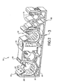
Fig. 3 is an enlarged portion ofFig. 2 . -
Fig. 4 is a partial cross-sectional view of the two-shot tube retention pocket tube clamp and a tube prior to insertion into the pocket. -
Fig. 5 is a partial cross-sectional view similar toFig. 4 , with the tube being inserted into the pocket. -
Fig. 6 is a partial cross-sectional view similar toFig. 4 , with the tube fully seated in the pocket. -
Fig. 7 is a partial perspective view of a first mold member for forming the two-shot tube retention pocket tube clamp ofFig. 1 and perspective illustrations representing second and third mold members. -
Fig. 8 is an enlarged partial cross-sectional view of the first mold member ofFig. 7 . -
Fig. 9 is an enlarged partial cross-sectional view similar toFig. 8 , including a corresponding portion of the body member formed using the first and second mold members. - Corresponding reference numerals indicate corresponding parts throughout the several views of the drawings.
- Example embodiments will now be described more fully with reference to the accompanying drawings.
- Referring to
Figs. 1-6 , one exemplarytube retention fastener 20 in accordance with the present disclosure is illustrated. Thetube retention fastener 20, includes abody 22 that is made of a first, relatively rigid polymeric material, and anisolation member 24 that is made of an elastically resilient second material. Thetube retention fastener 20 can be molded using a two-shot molding process in which thebody 22 is molded during a first shot, and then the isolation orsecond shot member 24 is molded in a second shot so that theisolation member 24 is coupled to and against surfaces of the body orfirst shot member 22. - The
tube retention fastener 20 includes a pair ofside walls 26 with asemi-circular sleeve 28 positioned between theside walls 26. As illustrated, theside walls 26 andsemi-circular sleeve 28 in combination can define a U-shapedlongitudinal pocket 30. Thetube retention fastener 20 includes a pair of deflectingwings 32. Each deflectingwing 32 is coupled to one of theside walls 26 forming acorner 34. Each deflectingwing 32 having a non-deflected position in which thedeflecting wing 32 angularly extends from therespective side wall 26 toward a central longitudinal axis 39 of the U-shapedlongitudinal pocket 30. - Each deflecting
wing 32 further includes a portion of theisolation member 24 bonded to aninterior surface 38 of the deflectingwing 32. As illustrated, theisolation member 24 can be bonded to a continuous portion of theinterior surface 38 of each deflectingwing 32 that extends from adistal end 40 of each deflectingwing 32 to itscorner 34 or junction with itsside wall 26. The continuous portion of theinterior surface 38 of thebody 22 to which the isolation member is bonded can further extend from eachcorner 34 over each of theside walls 26 and over thesemi-circular sleeve 28. Thus, eachcorner 34 can define a hinge point for both thebody 22 portion and theisolation member 24 portion bonded at thecorner 34 to thebody 22 portion of the deflectingwing 34. - All or part of the
exterior surface 42 of the deflectingwings 32 can be free of theisolation member 24. A portion of theinterior surface 38 of thelongitudinal pocket 30 of thebody 22 can be free of theisolation member 24. As seen best inFig. 3 , this isolation member-free portion 44 of theinterior surface 38 can be an outer band, offset, ornotch 44 adjacent the longitudinal end, edge or face 46 of thebody 22. The outer band, offset, ornotch 44 can provide the frontlongitudinal end face 25 of theisolation member 24 that is set-back relative to the frontlongitudinal end face 23 of thebody member 22. A similar isolation member-free portion 44 of theinterior surface 38, which can be in the form of a set-back, band, ornotch 44, can also be provided at the opposite longitudinal end, edge, or opposing back face 46 of thebody 22. - Such an isolation member-free portion or
portions 44 of theinterior surface 38 can be limited to the deflectingwings 32; that is, between thedistal end 40 and itscorner 34. As illustrated, an isolation member-free portion orportions 44 of theinterior surface 38 can also be provided adjacent theside walls 26; that is, between thecorners 34 and thesemi-circular sleeve 28. Similarly, anisolation member 24 free portion or portions of theinterior surface 38 can also be provided on thesemi-circular sleeve 28; that is, between theside walls 26. As illustrated, the isolation member-free portion 44 can extend continuously adjacent anisolation member 24 that is continuously bonded from the distal end of eachwing 32, to eachadjacent corner 34, throughout eachadjacent side wall 26, and throughout thesemi-circular sleeve 28. - Referring to
Figs. 4-6 , showing atubular member 48 prior to insertion into, during insertion into, and after insertion into thelongitudinal pocket 30 of thetube retention fastener 20, respectively. During insertion, as seen inFig. 5 , each deflectingwing 32 is able to fold flat against theside wall 26 to which the deflectingwing 32 is directly coupled. As illustrated, the portion of theisolation member 24 bonded to the interior surface of each deflectingwing 32 is able to engage the portion of theisolation material 24 bonded to the interior surface of theadjacent side wall 26 in a face-to-face orientation along the entire length of the deflectingwing 32. Theisolation member 24 includes apre-molded corner 34. There is no need to create a corner or bend in theisolation material 24 as the deflectingwings 32 move from a non-deflected position such as shown inFig. 4 into a deflected position shown inFig. 5 . - In addition, there is no open space required between the deflecting
wing 32 and theadjacent side wall 26. As seen inFig. 5 , each of the pair of deflectingwings 32 has a deflected position in which a wing portion of theisolation member 24 that is bonded to each deflectingwing 32 along a first span between acorner 34 and adistal end 40 of the deflectingwing 32 can contact in a face-to-face relationship against aside wall 36 portion of theisolation member 24 that is bonded to anadjacent side wall 36 along a second span between thecorner 34 and thesemi-circular sleeve 28. The illustrated configuration enables the distance between theside walls 26 to be reduced or minimized for any desiredtubular member 48 diameter or throat opening size or distance between the deflectingwings 32 in their deflected positions. - The
isolation member 24 includes a series of interiorlongitudinal ribs 50 extending longitudinally around the longitudinaltube holding pocket 30. The uppermost ribs 51 (relative to the deflecting wings 32) can define an entry throat T that is narrower than a diameter defined by the plurality oflongitudinal ribs 50. These uppermostlongitudinal ribs 51 are also above thelongitudinal axis 36 defined by the remainingribs 50, are adjacent theside wall 26 instead of thesemi-circular sleeve 28, and have a height dimension or form a thickness of theisolation member 24 that is larger than the height of or thickness formed at the otherlongitudinal ribs 50 below thelongitudinal axis 36. In addition to defining the entry throat opening T, the uppermostlongitudinal ribs 51 operate to center thetubular member 48 in the longitudinaltube holding pocket 30 during insertion. - The
tube retention fastener 20 can include a secondtube retention pocket 31 having all or some combination of similar features to those illustrated and described in relation toretention pocket 30. Thebody 22 can include aflow channel 49 which can provide a passageway allowing the elastically resilient isolation material to flow between or to bothpockets isolation member 24 for eachpocket tube retention fastener 22 can include other features including tube retention pockets 33 without any associated elastically resilient isolation material ormember 24, and afastener opening 35 structured to receive a fastener, such as a threaded fastener. - Referring to
Figs. 7-9 , threemold members tube retention fastener 20 such as exemplified above. Thefirst mold member 52 is positioned or mated with thesecond mold member 54 to form afirst shot cavity 58 that defines the body orfirst shot member 22. Thisfirst shot cavity 58 is represented inFig. 7 as an annular recess that is narrow, since it combines with thefirst mold member 52 to define the thickness of only thefirst shot member 22. Thefirst mold member 52 is positioned or mated with thethird mold member 56, with thefirst shot member 22 remaining with thefirst mold member 52, to form asecond shot cavity 60 that defines the isolation orsecond shot member 24. Thissecond shot cavity 60 is represented inFig. 7 as an annular recess that is wider, since it combines with thefirst mold member 52 to define thesecond shot member 24 while accounting for the presence of thefirst shot member 22 within themold pair - The
first mold member 52 includes a pair ofsurfaces 62 that each form the outer surface 63 of thebody member 22 portion of thewings 32. This outer surface 63 is oppositely disposed to theinterior surface 38 of thewings 32 to which theisolation member 24 is bonded. Eachsurface 62 of thefirst mold member 52 can remain in contact with the outer surface 63 of thecorresponding wing 32 of the firstshot body member 22 once formed, until after completion of the second shot operation forming the secondshot isolation member 24 against theinterior surface 38 of thewings 32 of the firstshot body member 22. Thus, the pair of mold surfaces 62 can provide support for thewings 32 during the second shot molding operation so that the first shot body member portion of thewings 32 do not disadvantageously deflect while molding the secondshot isolation member 24 to theinterior surface 38 of thewings 32. As a result, the second shot molding operation can be performed more quickly and prior to complete cooling of the relatively rigid polymeric material forming firstshot body member 22. - The
first mold member 52 can also include asurface 64 for eachwing 32 that contacts against a longitudinal edge orband 44 of theinterior surface 38 of thewings 32 of the firstshot body member 22. Portions of theinterior surface 38 of thewings 32 of the firstshot body member 22 are left unsupported, so the unsupportedinterior surface 38 defines a portion of themold cavity 58 of thesecond shot member 24 that can extend from a distal end of thewings 32 through to theadjacent corner 34 or pair ofside walls 26 of the firstshot body member 22. - The interior first shot member
wing supporting surface 64 and part of the exterior first shot memberwing supporting surface 62 can be provided in thefirst mold member 52 by agroove 66 in thefirst mold member 52. As should be apparent from the discussion above, the outer band, set-back, or notch 44 adjacent the longitudinal end, edge or face 46 of thebody 22 can result from the interior first shot memberwing supporting surface 64 orgroove 66 of thefirst mold member 52. Thethird mold member 56 in combination with thefirst mold member 52 and the firstshot body member 22 can define asecond shot member 24cavity 60 partially defined by an exposedbonding surface 68 of thefirst shot member 22 continuously extending from adistal end 40 of each deflectingwing 32 to theadjacent corner 34. - The
first mold member 52 can includesurfaces side walls 26 and thesemi-circular sleeve 28, respectively. Some or all of these interior supportingsurfaces groove 66. The exposedbonding surface 68 of thefirst shot member 24 can extend continuously from a distal end a deflectingwing 32, over the deflectingwing 32, over theadjacent side wall 26, over thesemi-circular sleeve 28, over theother side wall 26, over and to adistal end 40 of the other deflectingwing 32. - Corresponding or oppositely disposed interior first shot member
wing supporting surface 62 can be provided as part of thethird mold member 56 to support thewing 32 at its opposite longitudinal end, edge, or face 46 forming a corresponding opposite outer band, set-back, or notch 44. Similarly, corresponding or oppositely disposed interior supportingsurfaces bonding surface 68 can continuously extend over theside walls 26 andsemi-circular sleeve 28 portions of the firstshot body member 24 as well. - Two-shot tube retention fastener molding methods should be apparent from the above. For example, a first
shot body member 24 including a pair of deflectingwings 32 can be molded by combining afirst mold member 52 and asecond mold member 54 to form a first shotbody member cavity 58. Thefirst mold member 52 holding the firstshot body member 22 can be combined with athird mold member 56 to form a second shotbody member cavity 60. During the molding of the secondshot isolation member 24 an exterior wing surface of each deflectingwing 32 can be supported by asurface 62 of thefirst mold member 52. In addition, during the second shot molding operation, asurface 64 of thefirst mold member 52 can also support interior wing surface portions of each of the pair of deflectingwings 32, while leaving an interiorwing bonding surface 68 exposed to define a portion of the second shotisolation member cavity 60. - Interior portions of the
side walls 26 andsemi-circular sleeve 28 of the firstshot body member 22 can also be supported bysurfaces first mold member 52 during molding of the secondshot isolation member 24. Molding the secondshot isolation member 24 can also involve supporting corresponding interior surfaces at the opposite longitudinal end of thepocket 31 by providingcorresponding surfaces third mold member 60. As previously described, the exposedbonding surface 68 defining thesecond shot cavity 60 can continuously extend over the entire length of any or all of thewings 32, thecorner 34, theside walls 26, and thesemi-circular sleeve 28. - Example embodiments are provided so that this disclosure will be thorough, and will fully convey the scope to those who are skilled in the art. Numerous specific details are set forth such as examples of specific components, devices, and methods to provide a thorough understanding of embodiments of the present disclosure. It will be apparent to those skilled in the art that specific details need not be employed, that example embodiments may be embodied in many different forms and that neither should be construed to limit the scope of the disclosure. In some example embodiments, well-known processes, well-known device structures, and well-known technologies are not described in detail.
- The terminology used herein is for the purpose of describing particular example embodiments only, and is not intended to be limiting. The method steps, processes, and operations described herein are not to be construed as necessarily requiring their performance in the particular order discussed or illustrated, unless specifically identified as an order of performance. It is also to be understood that additional or alternative steps may be employed.
- Although the terms first, second, third, etc., may be used herein to describe various elements, components, regions, layers and/or sections, these elements, components, regions, layers and/or sections should not be limited by these terms. These terms may be only used to distinguish one element, component, region, layer or section from another region, layer or section. Terms such as "first," "second," and other numerical terms when used herein do not imply a sequence or order unless clearly indicated by the context. Thus, a first element, component, region, layer or section discussed below could be termed a second element, component, region, layer or section without departing from the teachings of the example embodiments.
- The foregoing description of the embodiments has been provided for purposes of illustration and description. It is not intended to be exhaustive or to limit the disclosure. Individual elements or features of a particular embodiment are generally not limited to that particular embodiment, but, where applicable, can be combined with any combination of features of other embodiments, even if not specifically shown or described. The same may also be varied in many ways. Such variations are not to be regarded as a departure from the disclosure, and all such modifications are intended to be included within the scope of the disclosure.
The following paragraphs are clauses that are worded like claims but are part of the description and include additional original disclosure for inventions. -
Clause 1. A tube retention fastener, comprising:- a body of a first polymeric material, the body including:
- a pair of side walls;
- a semi-circular sleeve positioned between the pair of side walls to define a portion of a longitudinal pocket;
- a pair of deflecting wings, each of the pair of deflecting wings being coupled to one of the pair of side walls at one of a pair of corners, respectively, each deflecting wing extending toward a central plane passing through a longitudinal axis of the longitudinal pocket in a non-deflected position;
- wherein the pair of side walls, the semi-circular sleeve, the pair of corners, and the pair of deflecting wings together define an interior surface of the longitudinal pocket;
- an isolation member of an elastically resilient second material bonded to portions of an interior surface of the longitudinal pocket defined by each of: the semi-circular sleeve, each of the pair of side walls, each of the pair of corners, and each of the pair of deflecting wings, and leaving a space between inner surfaces of the isolation member adjacent each corner.
- a body of a first polymeric material, the body including:
- Clause 2. The tube retention fastener of
Clause 1, wherein each one of the pair of corners defines a hinge point for both an isolation member portion and a body portion of an adjacent one of the pair of deflecting wings. - Clause 3. The tube retention fastener of any of the preceding Clauses, wherein each of the pair of deflecting wings has a deflected position in which a wing portion of the isolation member that is bonded to each deflecting wing along a first span between an adjacent one of the pair of corners and a distal end of the deflecting wing, contacts against a side wall portion of the isolation member that is bonded to an adjacent one of the pair of side walls along a second span between the adjacent one of the pair of corners and the semi-circular sleeve.
- Clause 4. The tube retention fastener of any of the preceding Clauses, wherein a wing longitudinal end face of the isolation member is interiorly offset from a wing longitudinal end face of the body adjacent each of the pair of deflecting wings.
- Clause 5. The tube retention fastener of any of the preceding Clauses, wherein the wing longitudinal end face of the isolation member is interiorly offset from the wing longitudinal end face of the body adjacent an entire wing length of each of the pair of deflecting wings from the respective first and second corner to the respective first and second distal ends.
- Clause 6. The tube retention fastener of any of the preceding Clauses, wherein a longitudinal end face of the isolation member is interiorly offset from a longitudinal end face of the body adjacent an entire longitudinal pocket length from the first corner along the first side wall, the semi-circular sleeve, and the second side wall to the second corner.
- Clause 7. The tube retention fastener of any of the preceding Clauses, wherein the resilient member further comprises a plurality of longitudinal ribs within the longitudinal pocket, and wherein a pair of opposing longitudinal ribs define an entry throat that is narrower than a diameter defined by the plurality of longitudinal ribs.
- Clause 8. The tube retention fastener of any of the preceding Clauses, wherein each of the pair of deflecting wings has a deflected position in which a distance between outer surfaces of each of the deflecting wings is larger than the entry throat.
- In summary, the invention may relate in one aspect to the following: A first shot body member includes a pair of side walls, a semi-circular sleeve positioned between the pair of side walls to define a portion of a longitudinal pocket, and a pair of deflecting wings. Each deflecting wing is coupled to one of the side walls at a corner. A second shot isolation member of an elastically resilient second material is bonded to portions of an interior surface of the longitudinal pocket defined by each of: the semi-circular sleeve, each of the pair of side walls, each of the pair of corners, and each of the pair of wings. Mold members can include supporting surfaces to support interior and exterior portions of the wing during the second shot molding operation, while leaving an exposed interior bonding surface that defines a portion of the second shot molding cavity. Related methods are further disclosed.
Claims (15)
- A two-shot tube retention fastener molding method, wherein the tube retention fastener (20) includes a first shot body member (22) having a pair of deflecting wings (32), with each of the pair of deflecting wings (32) extending angularly toward each other from one of a pair of side walls (24), and a second shot isolation member (24) bonded along an interior surface of each of the pair of deflecting wings (32), the method comprising:molding the first shot body member (22), including the pair of deflecting wings (32);molding the second shot isolation member (24) while:supporting an exterior wing surface (63) of each of the pair of deflecting wings (32) against a first mold surface (62);supporting a first interior wing surface portion (44) of each of the pair of deflecting wings (32) against a second mold surface (64) and leaving a second interior wing surface portion of each of the pair of deflecting wings (32) unsupported to define a portion of a mold cavity (58) of the second shot member (24) extending from a distal end (40) of the deflecting wing (32) to the pair of side walls (26).
- The two-shot tube retention fastener molding method of any of the preceding claims, wherein the supporting the first interior wing surface portion (44) comprises supporting an edge of the interior wing surface (38) adjacent a longitudinal end face of each of the pair of deflecting wings (32).
- The two-shot tube retention fastener molding method of any of the preceding claims, wherein the supporting the first interior wing surface portion (44) comprises supporting an edge of the interior surface (38) adjacent each opposing longitudinal end face of each of the pair of deflecting wings (32).
- The two-shot tube retention fastener molding method of any of the preceding claims, further comprising providing the first mold surface (62) and the second mold surface (64) on a single integral mold member (52).
- The two-shot tube retention fastener molding method of any of the preceding claims, wherein the supporting the exterior surface (63) and the supporting the portion (44) of the interior surface (38) comprises supporting a longitudinal end of each of the pair of deflecting wings (32) in a groove of a single integral mold member (52).
- The two-shot tube retention fastener molding method of any of the preceding claims, wherein the first shot member (22) further has a semi-circular sleeve (28) positioned between the pair of side walls (26), and the second shot member (24) is bonded to the first shot member (22) along an interior surface of the each of the pair of side walls (26) between the deflecting wings (32) and the
semi-circular sleeve (28), the method further comprising molding the second shot isolation member (24) while supporting a first interior wall surface portion of the each of the pair of side walls (26) and leaving a second interior wall surface portion of each of the pair of side walls (26) unsupported to define a second portion of the mold cavity of the second shot member extending from each pair of deflecting wing (32) to the semi-circular sleeve (28). - The two-shot tube retention fastener molding method of any of the preceding claims, further comprising molding the second shot isolation member (24) while supporting a first interior sleeve surface portion of a semi-circular sleeve (28) and leaving a third interior sleeve surface portion of semi-circular sleeve (28) unsupported to define a third portion of the mold cavity of the second shot member (24).
- The two-shot tube retention fastener molding method of any of of the preceding claims, wherein the molding the first shot body member (22) comprises forming the first shot body member of a polymeric material, and the molding the second shot isolation member (24) comprises forming the second shot isolation member of a relatively more flexible material than the first shot body member (22).
- A mold for a two-shot tube retention fastener comprising:a first mold member (52);a second mold member (54) that in combination with the first mold member defines a first shot member cavity (58) defining a first shot member (22) having a pair of deflecting wings (32), each of the pair of deflecting wings (32) extending angularly toward each other from one of a pair of side walls (26) and a semi-circular sleeve (28) positioned between the pair of side walls (26) to define a longitudinal tube-holding pocket (30);a third mold member (56) that in combination with the first mold member (52) and the first shot member (22) defines a second shot member cavity (60) partially defined by an exposed bonding surface (68) of the first shot member (22) continuously extending from a distal end of a first one of the pair of deflecting wings (32), over the first one of the deflecting wings (32), over a first one of the pair of side walls (26), over the semi-circular sleeve (28), over a second one of the pair of side walls (26), over a second one of the pair of deflecting wings (32), to a distal end of the second one of the deflecting wings (32);wherein, when the first and third mold members (52, 54, 56) are positioned with the first body shot member (22) for the second shot, the first mold member (52) comprises:first mold surfaces (62) supporting an exterior wing surface portion (63)of each of the pair of deflecting wings (32) of the first shot member (22);second mold surfaces (64) supporting an interior wing surface portion of each of the pair of deflecting wings (32) of the first shot member (22) while allowing for the continuously extending exposed surface over each deflecting wing (32).
- The mold for a two-shot tube retention fastener of Claim 9, wherein the first mold member (52) further comprises grooves (66) defining the second mold surfaces (64) and partially defining the first mold surfaces (62).
- The mold for a two-shot tube retention fastener of any of Claims 9-10, wherein the first mold member (52) further comprises third mold surfaces supporting an interior surface portion of the pair of side walls (26) while allowing for the exposed bonding surface to continuously extend over the first one of the pair of side walls (26).
- The mold for a two-shot tube retention fastener of any of Claims 9-11, wherein the first mold member (52) further comprises a fourth mold surface supporting an interior surface portion of the semi-circular sleeve (28) while allowing for the exposed bonding surface to continuously extend over the semi-circular sleeve (28).
- The mold for a two-shot tube retention fastener of any of Claims 9-12, wherein the first mold member (52) further comprises a groove defining each of the second, third, and fourth mold surfaces, and partially defining the first mold surface.
- The mold for a two-shot tube retention fastener of any of Claims 9-13, wherein, when the first and third mold members (52, 54, 56) are positioned with the first body shot member (22) for the second shot, the third mold member (56) comprises:corresponding first mold surfaces (62) supporting an exterior wing surface portion of each of the pair of deflecting wings (32) of the first shot member (22);corresponding second mold surfaces (64) supporting an interior wing surface portion (44) of each of the pair of deflecting wings (32) of the first shot member (22) while allowing for the exposed bonding surface to continuously extend over each deflecting wing (32).
- The mold for a two-shot tube retention fastener of any of Claims 9-14, wherein, when the first and third mold members (52, 54, 56) are positioned with the first body shot member (22) for the second shot, the first member (52) comprises:third mold surfaces supporting an interior surface portion of the pair of side walls (26) while allowing for the exposed bonding surface to continuously extend over the first one of the pair of side walls (26); anda fourth mold surface supporting an interior surface portion of the semi-circular sleeve (28) while allowing for the exposed bonding surface to continuously extend over the semi-circular sleeve (28); and
the third mold member comprises:corresponding third mold surfaces supporting an interior surface portion of the first one of the pair of side walls (26) while allowing for the exposed bonding surface to continuously extend over the first one of the pair of side walls (26); anda corresponding fourth mold surface supporting an interior surface portion of a second one of the pair of side walls (26) while allowing for the exposed bonding surface to continuously extend over the second one of the pair of side walls (26).
Applications Claiming Priority (1)
| Application Number | Priority Date | Filing Date | Title |
|---|---|---|---|
| US14/319,830 US9541223B2 (en) | 2014-06-30 | 2014-06-30 | Two-shot tube retention pocket tube clamp, mold and process |
Publications (2)
| Publication Number | Publication Date |
|---|---|
| EP2962831A1 true EP2962831A1 (en) | 2016-01-06 |
| EP2962831B1 EP2962831B1 (en) | 2019-01-16 |
Family
ID=53719602
Family Applications (1)
| Application Number | Title | Priority Date | Filing Date |
|---|---|---|---|
| EP15169572.3A Active EP2962831B1 (en) | 2014-06-30 | 2015-05-28 | Method and mould for multi-component injection moulding of a tube retention clamp |
Country Status (3)
| Country | Link |
|---|---|
| US (2) | US9541223B2 (en) |
| EP (1) | EP2962831B1 (en) |
| JP (1) | JP6666660B2 (en) |
Cited By (2)
| Publication number | Priority date | Publication date | Assignee | Title |
|---|---|---|---|---|
| CN105883543A (en) * | 2016-04-15 | 2016-08-24 | 周安平 | Lift shaft LED lamp |
| WO2024179650A1 (en) * | 2023-02-28 | 2024-09-06 | Gudmandsen Jeppe Holm | Device for organizing hoses and cables on operating tables |
Families Citing this family (25)
| Publication number | Priority date | Publication date | Assignee | Title |
|---|---|---|---|---|
| JP6160871B2 (en) * | 2014-03-27 | 2017-07-12 | 豊田合成株式会社 | Vehicle fueling device |
| JP2017061262A (en) * | 2015-09-25 | 2017-03-30 | 豊田合成株式会社 | Fuel supply apparatus |
| US10502607B2 (en) * | 2015-10-28 | 2019-12-10 | Honeywell International Inc. | Twin rod clip spacer |
| EP3464975A1 (en) | 2016-06-06 | 2019-04-10 | Spider Clip L.L.C. | Water pipe retainer |
| CA3228953A1 (en) * | 2017-01-06 | 2018-07-12 | Valmont Industries, Inc. | Improved cross arm support structure |
| DE102017102331B4 (en) | 2017-02-07 | 2020-08-13 | A. Raymond Et Cie Scs | Retaining element for a line |
| US10355409B2 (en) * | 2017-06-27 | 2019-07-16 | Aptiv Technologies Limited | Wiring-harness with connector staging device |
| CA3071463C (en) * | 2017-08-30 | 2021-07-20 | Richard Martin BRANDVOLD | Cable support bracket |
| DE102018200943B4 (en) * | 2018-01-22 | 2019-08-08 | Ford Global Technologies, Llc | Retaining clip for mounting vehicle parts in a vehicle |
| DE102018103666B4 (en) * | 2018-02-19 | 2021-07-01 | PSZ electronic GmbH | Fastening clip element for fastening and arranging pipe, hose or sheathed cables |
| KR20190113594A (en) * | 2018-03-27 | 2019-10-08 | 일리노이즈 툴 워크스 인코포레이티드 | Line securement lock |
| JP7252752B2 (en) * | 2018-12-20 | 2023-04-05 | 大和化成工業株式会社 | Bracket for electronic control parts |
| US11471344B1 (en) * | 2019-03-14 | 2022-10-18 | Cody Turnbow | Wheelchair handle grip |
| CN110141749B (en) * | 2019-05-21 | 2021-05-11 | 中国人民解放军陆军军医大学第一附属医院 | Connecting device between oxygen infuser and air bag |
| EP3990856A1 (en) | 2019-06-27 | 2022-05-04 | ESPI France | Machine and method for inspecting mechanical parts |
| WO2021050768A1 (en) * | 2019-09-11 | 2021-03-18 | Contech Medical, Inc. | Systems and methods for securing medical devices |
| JP7491698B2 (en) * | 2020-01-17 | 2024-05-28 | イリノイ トゥール ワークス インコーポレイティド | Clip Assembly for Cylindrical Parts |
| US11519541B2 (en) * | 2020-03-27 | 2022-12-06 | Pall Corporation | Tube retainers, tube retainer sets, and tube management systems |
| CN111503413A (en) * | 2020-04-25 | 2020-08-07 | 南京奥新可工程科技有限公司 | Pipeline fixing device for sewage treatment |
| CN111688113B (en) * | 2020-06-22 | 2022-03-25 | 芜湖浩博科技有限公司 | Feeding device for four-hole pipe clamp injection molding machine |
| CN116234725A (en) * | 2020-07-22 | 2023-06-06 | 住友电装株式会社 | Wire harness |
| DE102021128021B4 (en) * | 2020-11-04 | 2025-02-20 | Illinois Tool Works Inc. | PIPE HOLDING CLIP |
| JP7616008B2 (en) * | 2021-10-22 | 2025-01-17 | 住友電装株式会社 | Wire Harness |
| CN116946039B (en) * | 2023-07-28 | 2023-12-26 | 合肥寅翔新材料科技有限公司 | Cable multistage beam line structure for new energy automobile communication |
| US12535154B2 (en) | 2023-10-31 | 2026-01-27 | Cooper-Standard Automotive Inc. | Tubing clip |
Citations (5)
| Publication number | Priority date | Publication date | Assignee | Title |
|---|---|---|---|---|
| US4743422A (en) * | 1985-01-14 | 1988-05-10 | Kalriis Nielsen Erling | Method for manufacturing a sealing body for a pipe joint |
| EP1013978A2 (en) * | 1998-12-15 | 2000-06-28 | TRW Automotive Electronics & Components GmbH & Co. KG | Plastic fastening device |
| US20050067548A1 (en) * | 2003-09-30 | 2005-03-31 | Tomoki Inoue | Bracket for fluid transport tube |
| DE60117115T2 (en) * | 2000-11-24 | 2006-08-31 | Newfrey Llc, Newark | Snap arrangement for releasably securing an object to at least one line |
| US20130146720A1 (en) * | 2011-12-13 | 2013-06-13 | Jason A. Meyers | Two Shot Tube Retention Fastener with Anti Material Peeling Feature |
Family Cites Families (43)
| Publication number | Priority date | Publication date | Assignee | Title |
|---|---|---|---|---|
| US2438523A (en) * | 1944-08-21 | 1948-03-30 | Tinnerman Products Inc | Fastening device |
| DE3002031C2 (en) | 1980-01-21 | 1982-07-15 | United-Carr Gmbh, 6000 Frankfurt | Retaining element for at least one pipeline, in particular a gasoline line in a motor vehicle |
| US4511107A (en) * | 1982-08-27 | 1985-04-16 | Funk Richard J | One-piece clamp |
| DE3416020A1 (en) * | 1984-04-30 | 1985-10-31 | Fa. A. Raymond, 7850 Lörrach | PIPE CLAMP FOR BRAKE LINES |
| DE3708864A1 (en) * | 1987-03-18 | 1988-09-29 | United Carr Gmbh Trw | PLASTIC HOLDING ELEMENT |
| JPH0444581A (en) | 1990-06-11 | 1992-02-14 | Matsushita Electric Ind Co Ltd | locking device |
| JPH0444581U (en) * | 1990-08-22 | 1992-04-15 | ||
| DE4034545A1 (en) | 1990-10-30 | 1992-05-07 | United Carr Gmbh Trw | TWO-PIECE PLASTIC HOLDING ELEMENT |
| DE4039822C1 (en) | 1990-12-13 | 1992-07-23 | A. Raymond Kg, 7850 Loerrach, De | |
| US5301917A (en) * | 1992-11-23 | 1994-04-12 | Tyton Corporation | Brake line isolator |
| FR2704027B1 (en) | 1993-04-13 | 1995-12-01 | Trw Carr France Sa | Retaining element, in particular for bodywork of motor vehicles. |
| US5535969A (en) * | 1994-03-14 | 1996-07-16 | Illinois Tool Works Inc. | Fold over scissors clip |
| JPH112368A (en) | 1997-06-10 | 1999-01-06 | Pop Rivet Fastener Kk | Fixture for pipe-shaped member and manufacture thereof |
| US20040217236A1 (en) * | 2001-03-28 | 2004-11-04 | Tomio Shibuya | Vibration-proof clamp |
| US6809257B2 (en) | 2001-06-22 | 2004-10-26 | Newfrey Llc | Capped clip for pipe, electric cable or the like |
| US7165789B2 (en) | 2001-10-26 | 2007-01-23 | Salco Products, Inc. | Clamp assembly |
| DE10159277B4 (en) * | 2001-12-04 | 2012-06-06 | Newfrey Llc | Mobile arch holder for elongated objects |
| CA2373761C (en) | 2002-02-27 | 2007-01-16 | Itw Canada Inc. | Two shot molding method and fastener clip with seal made thereby |
| US6899304B2 (en) * | 2002-04-11 | 2005-05-31 | Ligon Brothers Manufacturing | Method for forming a fastener |
| FR2843438B1 (en) | 2002-08-09 | 2005-02-11 | Amphenol Air Lb | DEVICE FOR MAINTAINING PIPING SYSTEMS |
| JP4002812B2 (en) | 2002-10-08 | 2007-11-07 | 株式会社ニフコ | Clamp |
| JP2004242478A (en) | 2003-02-10 | 2004-08-26 | Nippon Pop Rivets & Fasteners Ltd | Cable clamp |
| DE10306905C5 (en) * | 2003-02-18 | 2012-05-24 | Itw Automotive Products Gmbh & Co. Kg | retaining element |
| DE10306904C5 (en) | 2003-02-18 | 2012-05-03 | Itw Automotive Products Gmbh & Co. Kg | retaining element |
| JP2004308788A (en) | 2003-04-07 | 2004-11-04 | Nippon Pop Rivets & Fasteners Ltd | Anti-vibration clamp for pipes, etc. |
| US6926237B2 (en) | 2003-05-29 | 2005-08-09 | Illinois Tool Works Inc. | Vibration damping clip |
| US7278190B2 (en) | 2003-07-03 | 2007-10-09 | Newfrey Llc | Two component fuel and brake line clip |
| JP2005076803A (en) * | 2003-09-02 | 2005-03-24 | Nippon Pop Rivets & Fasteners Ltd | Vibration-proofing clamp for pipe or the like |
| US20050098688A1 (en) | 2003-11-10 | 2005-05-12 | Itt Manufacturing Enterprises, Inc. | Multi-material isolator bundle clip |
| JP2005147186A (en) | 2003-11-12 | 2005-06-09 | Nippon Pop Rivets & Fasteners Ltd | Holder |
| DE202004008388U1 (en) * | 2004-05-26 | 2004-08-05 | Böllhoff Verbindungstechnik GmbH | Connecting arrangement made of plastic for fixing a hose |
| JP4357374B2 (en) * | 2004-06-28 | 2009-11-04 | ポップリベット・ファスナー株式会社 | Heat-resistant clamping device for pipes |
| DE202005008570U1 (en) | 2005-06-01 | 2005-09-08 | Trw Automotive Electronics & Components Gmbh & Co. Kg | Cable e.g. hydraulic cable, fastening device for vehicle, has plastic film partially surrounding reinforcing part upto fastening section, gap for insertion of cable, and peripheral wall with flexible projections stretching inward |
| JP4898347B2 (en) * | 2006-08-24 | 2012-03-14 | ポップリベット・ファスナー株式会社 | Clamp for long members such as pipes |
| US20080052878A1 (en) * | 2006-08-31 | 2008-03-06 | Lewis Jeffrey C | Fastener Clip with Seal |
| DE102008036563A1 (en) * | 2008-07-30 | 2010-02-04 | Newfrey Llc, Newark | Holder for an elongated object |
| CN102159374B (en) * | 2008-09-22 | 2013-12-11 | 日本写真印刷株式会社 | Process for producing multilayered molded article and mold set for multilayered molded article |
| JP2010133543A (en) | 2008-12-08 | 2010-06-17 | Nippon Pop Rivets & Fasteners Ltd | Clamp of corrugated tube |
| US20100207001A1 (en) | 2009-02-13 | 2010-08-19 | Newfrey Llc | Conductive And Isolated 2-Shot Tube Clamp |
| JP5753169B2 (en) | 2009-09-02 | 2015-07-22 | イリノイ トゥール ワークス インコーポレイティド | Conductive floating pipe assembly clip |
| JP5694703B2 (en) | 2009-11-27 | 2015-04-01 | 株式会社ニフコ | Clamp |
| WO2011119411A1 (en) | 2010-03-24 | 2011-09-29 | Illinois Tool Works Inc. | Serviceable snap-in fastener |
| JP5848950B2 (en) * | 2011-10-28 | 2016-01-27 | 株式会社ニフコ | Anti-vibration clamp |
-
2014
- 2014-06-30 US US14/319,830 patent/US9541223B2/en active Active
-
2015
- 2015-05-28 EP EP15169572.3A patent/EP2962831B1/en active Active
- 2015-06-24 JP JP2015126408A patent/JP6666660B2/en active Active
-
2016
- 2016-10-31 US US15/339,647 patent/US10557569B2/en active Active
Patent Citations (5)
| Publication number | Priority date | Publication date | Assignee | Title |
|---|---|---|---|---|
| US4743422A (en) * | 1985-01-14 | 1988-05-10 | Kalriis Nielsen Erling | Method for manufacturing a sealing body for a pipe joint |
| EP1013978A2 (en) * | 1998-12-15 | 2000-06-28 | TRW Automotive Electronics & Components GmbH & Co. KG | Plastic fastening device |
| DE60117115T2 (en) * | 2000-11-24 | 2006-08-31 | Newfrey Llc, Newark | Snap arrangement for releasably securing an object to at least one line |
| US20050067548A1 (en) * | 2003-09-30 | 2005-03-31 | Tomoki Inoue | Bracket for fluid transport tube |
| US20130146720A1 (en) * | 2011-12-13 | 2013-06-13 | Jason A. Meyers | Two Shot Tube Retention Fastener with Anti Material Peeling Feature |
Cited By (3)
| Publication number | Priority date | Publication date | Assignee | Title |
|---|---|---|---|---|
| CN105883543A (en) * | 2016-04-15 | 2016-08-24 | 周安平 | Lift shaft LED lamp |
| CN105883543B (en) * | 2016-04-15 | 2018-03-23 | 周安平 | Elevator hoistways LED |
| WO2024179650A1 (en) * | 2023-02-28 | 2024-09-06 | Gudmandsen Jeppe Holm | Device for organizing hoses and cables on operating tables |
Also Published As
| Publication number | Publication date |
|---|---|
| US20170045160A1 (en) | 2017-02-16 |
| JP2016013691A (en) | 2016-01-28 |
| EP2962831B1 (en) | 2019-01-16 |
| US9541223B2 (en) | 2017-01-10 |
| US10557569B2 (en) | 2020-02-11 |
| US20150377387A1 (en) | 2015-12-31 |
| JP6666660B2 (en) | 2020-03-18 |
Similar Documents
| Publication | Publication Date | Title |
|---|---|---|
| EP2962831A1 (en) | Method and mould for multi-component injection moulding of a tube retention clamp | |
| US8733709B2 (en) | Two shot tube retention fastener with anti material peeling feature | |
| JP5753169B2 (en) | Conductive floating pipe assembly clip | |
| JP2023073495A (en) | Dual-component u-base fastener | |
| US10703194B2 (en) | Stiffening assembly for a fuel tank | |
| US10181676B2 (en) | Male connector | |
| US20160149385A1 (en) | Electric wire protection member | |
| CN105493366A (en) | Wire protection member | |
| JP6419518B2 (en) | Insert molding method using insert mold | |
| US10122097B2 (en) | Molded portion-equipped electric wire | |
| CN106870831A (en) | The pipe of belt lacing | |
| US10569807B2 (en) | Side sill molding for car and manufacturing method thereof | |
| WO2013132710A1 (en) | Fixture for mounting slit-mounted member, method for manufacturing wire harness, and slit-mounted member | |
| CN103574176A (en) | Device for the passage of cables and pipes, for electrical applications and the like | |
| US10153070B2 (en) | Waterproof structure of wire harness | |
| JP3207552U (en) | Piping sleeve | |
| EP2233850B1 (en) | Coupling system comprising a ribbed hose, packing and channel piece | |
| EP2957407B1 (en) | Method of manufacturing a cable with a resin molded body | |
| JP2017025967A (en) | Shell | |
| JP4648763B2 (en) | Pipe fitting | |
| JP6134774B2 (en) | Cable fixing device | |
| JP2020112233A (en) | T type fitting | |
| JP2007182101A (en) | Vehicular air-conditioning duct | |
| CN114286911A (en) | Flow path structure | |
| JP2006032126A (en) | Grommet |
Legal Events
| Date | Code | Title | Description |
|---|---|---|---|
| PUAI | Public reference made under article 153(3) epc to a published international application that has entered the european phase |
Free format text: ORIGINAL CODE: 0009012 |
|
| AK | Designated contracting states |
Kind code of ref document: A1 Designated state(s): AL AT BE BG CH CY CZ DE DK EE ES FI FR GB GR HR HU IE IS IT LI LT LU LV MC MK MT NL NO PL PT RO RS SE SI SK SM TR |
|
| AX | Request for extension of the european patent |
Extension state: BA ME |
|
| RIN1 | Information on inventor provided before grant (corrected) |
Inventor name: PILON, ROGER E. Inventor name: MEYERS, JASON AARON Inventor name: DIEP, TIEN T. |
|
| RAP1 | Party data changed (applicant data changed or rights of an application transferred) |
Owner name: NEWFREY LLC |
|
| 17P | Request for examination filed |
Effective date: 20160701 |
|
| RBV | Designated contracting states (corrected) |
Designated state(s): AL AT BE BG CH CY CZ DE DK EE ES FI FR GB GR HR HU IE IS IT LI LT LU LV MC MK MT NL NO PL PT RO RS SE SI SK SM TR |
|
| STAA | Information on the status of an ep patent application or granted ep patent |
Free format text: STATUS: EXAMINATION IS IN PROGRESS |
|
| 17Q | First examination report despatched |
Effective date: 20161115 |
|
| GRAP | Despatch of communication of intention to grant a patent |
Free format text: ORIGINAL CODE: EPIDOSNIGR1 |
|
| STAA | Information on the status of an ep patent application or granted ep patent |
Free format text: STATUS: GRANT OF PATENT IS INTENDED |
|
| INTG | Intention to grant announced |
Effective date: 20180731 |
|
| GRAS | Grant fee paid |
Free format text: ORIGINAL CODE: EPIDOSNIGR3 |
|
| GRAA | (expected) grant |
Free format text: ORIGINAL CODE: 0009210 |
|
| STAA | Information on the status of an ep patent application or granted ep patent |
Free format text: STATUS: THE PATENT HAS BEEN GRANTED |
|
| AK | Designated contracting states |
Kind code of ref document: B1 Designated state(s): AL AT BE BG CH CY CZ DE DK EE ES FI FR GB GR HR HU IE IS IT LI LT LU LV MC MK MT NL NO PL PT RO RS SE SI SK SM TR |
|
| REG | Reference to a national code |
Ref country code: GB Ref legal event code: FG4D |
|
| REG | Reference to a national code |
Ref country code: CH Ref legal event code: EP |
|
| REG | Reference to a national code |
Ref country code: IE Ref legal event code: FG4D |
|
| REG | Reference to a national code |
Ref country code: DE Ref legal event code: R096 Ref document number: 602015023498 Country of ref document: DE |
|
| REG | Reference to a national code |
Ref country code: AT Ref legal event code: REF Ref document number: 1089384 Country of ref document: AT Kind code of ref document: T Effective date: 20190215 |
|
| REG | Reference to a national code |
Ref country code: NL Ref legal event code: MP Effective date: 20190116 |
|
| REG | Reference to a national code |
Ref country code: LT Ref legal event code: MG4D |
|
| PG25 | Lapsed in a contracting state [announced via postgrant information from national office to epo] |
Ref country code: NL Free format text: LAPSE BECAUSE OF FAILURE TO SUBMIT A TRANSLATION OF THE DESCRIPTION OR TO PAY THE FEE WITHIN THE PRESCRIBED TIME-LIMIT Effective date: 20190116 |
|
| REG | Reference to a national code |
Ref country code: AT Ref legal event code: MK05 Ref document number: 1089384 Country of ref document: AT Kind code of ref document: T Effective date: 20190116 |
|
| PG25 | Lapsed in a contracting state [announced via postgrant information from national office to epo] |
Ref country code: ES Free format text: LAPSE BECAUSE OF FAILURE TO SUBMIT A TRANSLATION OF THE DESCRIPTION OR TO PAY THE FEE WITHIN THE PRESCRIBED TIME-LIMIT Effective date: 20190116 Ref country code: PT Free format text: LAPSE BECAUSE OF FAILURE TO SUBMIT A TRANSLATION OF THE DESCRIPTION OR TO PAY THE FEE WITHIN THE PRESCRIBED TIME-LIMIT Effective date: 20190516 Ref country code: NO Free format text: LAPSE BECAUSE OF FAILURE TO SUBMIT A TRANSLATION OF THE DESCRIPTION OR TO PAY THE FEE WITHIN THE PRESCRIBED TIME-LIMIT Effective date: 20190416 Ref country code: PL Free format text: LAPSE BECAUSE OF FAILURE TO SUBMIT A TRANSLATION OF THE DESCRIPTION OR TO PAY THE FEE WITHIN THE PRESCRIBED TIME-LIMIT Effective date: 20190116 Ref country code: LT Free format text: LAPSE BECAUSE OF FAILURE TO SUBMIT A TRANSLATION OF THE DESCRIPTION OR TO PAY THE FEE WITHIN THE PRESCRIBED TIME-LIMIT Effective date: 20190116 Ref country code: SE Free format text: LAPSE BECAUSE OF FAILURE TO SUBMIT A TRANSLATION OF THE DESCRIPTION OR TO PAY THE FEE WITHIN THE PRESCRIBED TIME-LIMIT Effective date: 20190116 Ref country code: FI Free format text: LAPSE BECAUSE OF FAILURE TO SUBMIT A TRANSLATION OF THE DESCRIPTION OR TO PAY THE FEE WITHIN THE PRESCRIBED TIME-LIMIT Effective date: 20190116 |
|
| PG25 | Lapsed in a contracting state [announced via postgrant information from national office to epo] |
Ref country code: RS Free format text: LAPSE BECAUSE OF FAILURE TO SUBMIT A TRANSLATION OF THE DESCRIPTION OR TO PAY THE FEE WITHIN THE PRESCRIBED TIME-LIMIT Effective date: 20190116 Ref country code: BG Free format text: LAPSE BECAUSE OF FAILURE TO SUBMIT A TRANSLATION OF THE DESCRIPTION OR TO PAY THE FEE WITHIN THE PRESCRIBED TIME-LIMIT Effective date: 20190416 Ref country code: LV Free format text: LAPSE BECAUSE OF FAILURE TO SUBMIT A TRANSLATION OF THE DESCRIPTION OR TO PAY THE FEE WITHIN THE PRESCRIBED TIME-LIMIT Effective date: 20190116 Ref country code: IS Free format text: LAPSE BECAUSE OF FAILURE TO SUBMIT A TRANSLATION OF THE DESCRIPTION OR TO PAY THE FEE WITHIN THE PRESCRIBED TIME-LIMIT Effective date: 20190516 Ref country code: HR Free format text: LAPSE BECAUSE OF FAILURE TO SUBMIT A TRANSLATION OF THE DESCRIPTION OR TO PAY THE FEE WITHIN THE PRESCRIBED TIME-LIMIT Effective date: 20190116 Ref country code: GR Free format text: LAPSE BECAUSE OF FAILURE TO SUBMIT A TRANSLATION OF THE DESCRIPTION OR TO PAY THE FEE WITHIN THE PRESCRIBED TIME-LIMIT Effective date: 20190417 |
|
| REG | Reference to a national code |
Ref country code: DE Ref legal event code: R097 Ref document number: 602015023498 Country of ref document: DE |
|
| PG25 | Lapsed in a contracting state [announced via postgrant information from national office to epo] |
Ref country code: SK Free format text: LAPSE BECAUSE OF FAILURE TO SUBMIT A TRANSLATION OF THE DESCRIPTION OR TO PAY THE FEE WITHIN THE PRESCRIBED TIME-LIMIT Effective date: 20190116 Ref country code: IT Free format text: LAPSE BECAUSE OF FAILURE TO SUBMIT A TRANSLATION OF THE DESCRIPTION OR TO PAY THE FEE WITHIN THE PRESCRIBED TIME-LIMIT Effective date: 20190116 Ref country code: EE Free format text: LAPSE BECAUSE OF FAILURE TO SUBMIT A TRANSLATION OF THE DESCRIPTION OR TO PAY THE FEE WITHIN THE PRESCRIBED TIME-LIMIT Effective date: 20190116 Ref country code: DK Free format text: LAPSE BECAUSE OF FAILURE TO SUBMIT A TRANSLATION OF THE DESCRIPTION OR TO PAY THE FEE WITHIN THE PRESCRIBED TIME-LIMIT Effective date: 20190116 Ref country code: AL Free format text: LAPSE BECAUSE OF FAILURE TO SUBMIT A TRANSLATION OF THE DESCRIPTION OR TO PAY THE FEE WITHIN THE PRESCRIBED TIME-LIMIT Effective date: 20190116 Ref country code: AT Free format text: LAPSE BECAUSE OF FAILURE TO SUBMIT A TRANSLATION OF THE DESCRIPTION OR TO PAY THE FEE WITHIN THE PRESCRIBED TIME-LIMIT Effective date: 20190116 Ref country code: CZ Free format text: LAPSE BECAUSE OF FAILURE TO SUBMIT A TRANSLATION OF THE DESCRIPTION OR TO PAY THE FEE WITHIN THE PRESCRIBED TIME-LIMIT Effective date: 20190116 Ref country code: RO Free format text: LAPSE BECAUSE OF FAILURE TO SUBMIT A TRANSLATION OF THE DESCRIPTION OR TO PAY THE FEE WITHIN THE PRESCRIBED TIME-LIMIT Effective date: 20190116 |
|
| PLBE | No opposition filed within time limit |
Free format text: ORIGINAL CODE: 0009261 |
|
| STAA | Information on the status of an ep patent application or granted ep patent |
Free format text: STATUS: NO OPPOSITION FILED WITHIN TIME LIMIT |
|
| PG25 | Lapsed in a contracting state [announced via postgrant information from national office to epo] |
Ref country code: SM Free format text: LAPSE BECAUSE OF FAILURE TO SUBMIT A TRANSLATION OF THE DESCRIPTION OR TO PAY THE FEE WITHIN THE PRESCRIBED TIME-LIMIT Effective date: 20190116 |
|
| 26N | No opposition filed |
Effective date: 20191017 |
|
| REG | Reference to a national code |
Ref country code: CH Ref legal event code: PL |
|
| PG25 | Lapsed in a contracting state [announced via postgrant information from national office to epo] |
Ref country code: CH Free format text: LAPSE BECAUSE OF NON-PAYMENT OF DUE FEES Effective date: 20190531 Ref country code: LI Free format text: LAPSE BECAUSE OF NON-PAYMENT OF DUE FEES Effective date: 20190531 Ref country code: MC Free format text: LAPSE BECAUSE OF FAILURE TO SUBMIT A TRANSLATION OF THE DESCRIPTION OR TO PAY THE FEE WITHIN THE PRESCRIBED TIME-LIMIT Effective date: 20190116 |
|
| REG | Reference to a national code |
Ref country code: BE Ref legal event code: MM Effective date: 20190531 |
|
| PG25 | Lapsed in a contracting state [announced via postgrant information from national office to epo] |
Ref country code: LU Free format text: LAPSE BECAUSE OF NON-PAYMENT OF DUE FEES Effective date: 20190528 Ref country code: SI Free format text: LAPSE BECAUSE OF FAILURE TO SUBMIT A TRANSLATION OF THE DESCRIPTION OR TO PAY THE FEE WITHIN THE PRESCRIBED TIME-LIMIT Effective date: 20190116 |
|
| PG25 | Lapsed in a contracting state [announced via postgrant information from national office to epo] |
Ref country code: TR Free format text: LAPSE BECAUSE OF FAILURE TO SUBMIT A TRANSLATION OF THE DESCRIPTION OR TO PAY THE FEE WITHIN THE PRESCRIBED TIME-LIMIT Effective date: 20190116 |
|
| PG25 | Lapsed in a contracting state [announced via postgrant information from national office to epo] |
Ref country code: IE Free format text: LAPSE BECAUSE OF NON-PAYMENT OF DUE FEES Effective date: 20190528 |
|
| PG25 | Lapsed in a contracting state [announced via postgrant information from national office to epo] |
Ref country code: BE Free format text: LAPSE BECAUSE OF NON-PAYMENT OF DUE FEES Effective date: 20190531 |
|
| PG25 | Lapsed in a contracting state [announced via postgrant information from national office to epo] |
Ref country code: CY Free format text: LAPSE BECAUSE OF FAILURE TO SUBMIT A TRANSLATION OF THE DESCRIPTION OR TO PAY THE FEE WITHIN THE PRESCRIBED TIME-LIMIT Effective date: 20190116 |
|
| PG25 | Lapsed in a contracting state [announced via postgrant information from national office to epo] |
Ref country code: HU Free format text: LAPSE BECAUSE OF FAILURE TO SUBMIT A TRANSLATION OF THE DESCRIPTION OR TO PAY THE FEE WITHIN THE PRESCRIBED TIME-LIMIT; INVALID AB INITIO Effective date: 20150528 Ref country code: MT Free format text: LAPSE BECAUSE OF FAILURE TO SUBMIT A TRANSLATION OF THE DESCRIPTION OR TO PAY THE FEE WITHIN THE PRESCRIBED TIME-LIMIT Effective date: 20190116 |
|
| PG25 | Lapsed in a contracting state [announced via postgrant information from national office to epo] |
Ref country code: MK Free format text: LAPSE BECAUSE OF FAILURE TO SUBMIT A TRANSLATION OF THE DESCRIPTION OR TO PAY THE FEE WITHIN THE PRESCRIBED TIME-LIMIT Effective date: 20190116 |
|
| REG | Reference to a national code |
Ref country code: FR Ref legal event code: PLFP Year of fee payment: 9 |
|
| P01 | Opt-out of the competence of the unified patent court (upc) registered |
Effective date: 20230912 |
|
| PGFP | Annual fee paid to national office [announced via postgrant information from national office to epo] |
Ref country code: DE Payment date: 20250519 Year of fee payment: 11 |
|
| PGFP | Annual fee paid to national office [announced via postgrant information from national office to epo] |
Ref country code: FR Payment date: 20250526 Year of fee payment: 11 |
|
| PGFP | Annual fee paid to national office [announced via postgrant information from national office to epo] |
Ref country code: GB Payment date: 20260324 Year of fee payment: 12 |