EP2962615B1 - Improvements to fluid-dispensing apparatus - Google Patents
Improvements to fluid-dispensing apparatus Download PDFInfo
- Publication number
- EP2962615B1 EP2962615B1 EP15174492.7A EP15174492A EP2962615B1 EP 2962615 B1 EP2962615 B1 EP 2962615B1 EP 15174492 A EP15174492 A EP 15174492A EP 2962615 B1 EP2962615 B1 EP 2962615B1
- Authority
- EP
- European Patent Office
- Prior art keywords
- handle
- flow control
- fluid
- control member
- dispensing apparatus
- Prior art date
- Legal status (The legal status is an assumption and is not a legal conclusion. Google has not performed a legal analysis and makes no representation as to the accuracy of the status listed.)
- Active
Links
Images


Classifications
-
- A—HUMAN NECESSITIES
- A47—FURNITURE; DOMESTIC ARTICLES OR APPLIANCES; COFFEE MILLS; SPICE MILLS; SUCTION CLEANERS IN GENERAL
- A47L—DOMESTIC WASHING OR CLEANING; SUCTION CLEANERS IN GENERAL
- A47L13/00—Implements for cleaning floors, carpets, furniture, walls, or wall coverings
- A47L13/10—Scrubbing; Scouring; Cleaning; Polishing
- A47L13/26—Other cleaning devices with liquid supply arrangements
-
- A—HUMAN NECESSITIES
- A46—BRUSHWARE
- A46B—BRUSHES
- A46B11/00—Brushes with reservoir or other means for applying substances, e.g. paints, pastes, water
- A46B11/001—Brushes with reservoir or other means for applying substances, e.g. paints, pastes, water with integral reservoirs
-
- A—HUMAN NECESSITIES
- A46—BRUSHWARE
- A46B—BRUSHES
- A46B11/00—Brushes with reservoir or other means for applying substances, e.g. paints, pastes, water
- A46B11/001—Brushes with reservoir or other means for applying substances, e.g. paints, pastes, water with integral reservoirs
- A46B11/0013—Brushes with reservoir or other means for applying substances, e.g. paints, pastes, water with integral reservoirs dispensing by gravity or by shaking
-
- A—HUMAN NECESSITIES
- A46—BRUSHWARE
- A46B—BRUSHES
- A46B11/00—Brushes with reservoir or other means for applying substances, e.g. paints, pastes, water
- A46B11/001—Brushes with reservoir or other means for applying substances, e.g. paints, pastes, water with integral reservoirs
- A46B11/002—Brushes with reservoir or other means for applying substances, e.g. paints, pastes, water with integral reservoirs pressurised at moment of use manually or by powered means
-
- A—HUMAN NECESSITIES
- A47—FURNITURE; DOMESTIC ARTICLES OR APPLIANCES; COFFEE MILLS; SPICE MILLS; SUCTION CLEANERS IN GENERAL
- A47L—DOMESTIC WASHING OR CLEANING; SUCTION CLEANERS IN GENERAL
- A47L13/00—Implements for cleaning floors, carpets, furniture, walls, or wall coverings
- A47L13/10—Scrubbing; Scouring; Cleaning; Polishing
- A47L13/20—Mops
- A47L13/22—Mops with liquid-feeding devices
-
- A—HUMAN NECESSITIES
- A47—FURNITURE; DOMESTIC ARTICLES OR APPLIANCES; COFFEE MILLS; SPICE MILLS; SUCTION CLEANERS IN GENERAL
- A47L—DOMESTIC WASHING OR CLEANING; SUCTION CLEANERS IN GENERAL
- A47L17/00—Apparatus or implements used in manual washing or cleaning of crockery, table-ware, cooking-ware or the like
- A47L17/04—Pan or pot cleaning utensils
-
- A—HUMAN NECESSITIES
- A47—FURNITURE; DOMESTIC ARTICLES OR APPLIANCES; COFFEE MILLS; SPICE MILLS; SUCTION CLEANERS IN GENERAL
- A47L—DOMESTIC WASHING OR CLEANING; SUCTION CLEANERS IN GENERAL
- A47L23/00—Cleaning footwear
- A47L23/04—Hand implements for shoe-cleaning, with or without applicators for shoe polish
- A47L23/05—Hand implements for shoe-cleaning, with or without applicators for shoe polish with applicators for shoe polish
-
- A—HUMAN NECESSITIES
- A46—BRUSHWARE
- A46B—BRUSHES
- A46B2200/00—Brushes characterized by their functions, uses or applications
- A46B2200/30—Brushes for cleaning or polishing
- A46B2200/3033—Household brush, i.e. brushes for cleaning in the house or dishes
-
- A—HUMAN NECESSITIES
- A46—BRUSHWARE
- A46B—BRUSHES
- A46B9/00—Arrangements of the bristles in the brush body
- A46B9/005—Arrangements of the bristles in the brush body where the brushing material is not made of bristles, e.g. sponge, rubber or paper
Definitions
- the present invention concerns an improved fluid-dispensing apparatus of the type comprising a hollow handle for dispensing fluid and carrying a working head such as a sponge, brush or the like.
- a working head such as a sponge, brush or the like.
- Such hand-held fluid-dispensing utensils are in particular useful for cleaning.
- Hand-held cleaning utensils that dispense fluid such as soap or detergent exist in a variety of forms.
- Such utensils typically include a fluid reservoir, a closeable opening for filling the reservoir, and means for dispensing the fluid from the reservoir to the cleaning head, comprising bristles or a sponge or the like. It is known to produce the working head as a detachable unit.
- the present invention seeks to provide inter alia improvements relating to such fluid-dispensing utensils.
- a fluid-dispensing apparatus comprising a hollow handle, a working head from which fluid may be dispensed and an intermediate member, the hollow handle providing an enclosure defining a fluid reservoir therein, the handle having a distal end portion and having an outlet located in the distal end portion, the working head having a dispensing aperture for dispensing of fluid, the intermediate member being configured to receive the distal end portion of the handle therein, the working head being attachable to the intermediate member, the intermediate member having a dispensing aperture, the dispensing aperture of the intermediate member being in alignment with the outlet of the handle and with the dispensing aperture of the working head when assembled.
- the dispensing aperture of the intermediate member is in registry with the dispensing aperture of the working head when assembled.
- the dispensing aperture of the intermediate member is also in registry with the outlet of the handle (whether directly or with another apertured member there between) when assembled.
- the outlet of the handle is located at or near the distal end of the distal end portion of the handle.
- the distal end portion of the handle extends into and is received within the intermediate member when assembled. The outlet of the handle is therefore received within the intermediate member when assembled. Part of the fluid enclosure provided by the handle effectively extends into and is housed within the intermediate member.
- the apparatus may be a cleaning utensil, preferably a hand-held utensil.
- the present arrangement provides an improvement over existing utensils in that the intermediate member, to which the working head attaches in the present invention, can be provided as a separate unit prior to manufacturing assembly, in different shapes and/or sizes to suit different uses. This provides efficiency in manufacturing of the utensil.
- the assembly described above also allows for means for controlling the flow of fluid from the fluid reservoir to be easily assembled as part of the utensil assembly, providing further efficiencies in manufacture.
- the apparatus further comprises a flow control member for controlling the flow of fluid from the handle, the flow control member being movable with respect to the handle outlet for selectively controlling the flow.
- the flow control member may be movable with respect to the handle outlet for selectively opening and closing the outlet and/or selectively controlling the level of flow.
- the flow control member is received within the intermediate member.
- the flow control member has a valve portion, the valve portion being received in a space between a surface of the handle and a surface of the intermediate member.
- the valve portion is received between the handle outlet and the dispensing aperture of the intermediate member.
- the valve portion suitably controls fluid flow from the fluid reservoir in the handle.
- valve portion of the flow control member has at least a first aperture, the valve portion being movable with respect to the handle outlet for selectively aligning the first aperture with the handle outlet. Since the handle outlet is aligned with the dispensing apertures of the intermediate member and working head, alignment of the first aperture with the outlet of the handle also aligns the first aperture with the dispensing apertures of the intermediate member and working head.
- the flow control member is movable between at least a first open position in which the first aperture is aligned with the handle outlet and a closed position in which part of the valve portion blocks the handle outlet. Fluid is blocked from flowing out of the handle outlet when the flow control member is in the closed position.
- the user can selectively move the flow control member between closed and open positions to selectively stop or allow fluid to be dispensed from the utensil. When the flow control member is in the closed position, this prevents leakage of the fluid from the handle (e.g. under gravity and capillary action), which is useful for when the apparatus is not in use.
- valve portion of the flow control member has at least first and second apertures of different sizes, the valve member being movable with respect to the handle outlet for selectively aligning the first or second aperture with the handle outlet.
- first and second apertures in the valve portion are circular apertures having differing diameters
- the flow control member is movable between first and second open positions corresponding to first and second discrete flow control positions, wherein when the flow control member is in the first open position the first aperture aligns with the handle outlet and in the second open position the second aperture aligns with the handle outlet.
- the flow control member can be maintained in an open position or closed position via detent action.
- one of the flow control member and an adjacent surface has a detent and the other has at least one detent recess for receiving the detent for maintaining the flow control member in a selected position via detent action.
- the flow control member has a detent and an adjacent surface of the handle has at least one detent recess for receiving the detent for maintaining the flow control member in a selected position via detent action.
- the handle has a first detent recess for receiving the detent to maintain the flow control member in the first open position, a second detent recess for receiving the detent to maintain the flow control member in the second open position, and a third detent recess for receiving the detent to maintain the flow control member in the closed position.
- the flow control member is slidably movable relative to the handle.
- the flow control member is linearly movable relative to the handle.
- the flow control member has a throughbore for receiving at least part of the distal end portion of the handle therethrough.
- the flow control member has an actuator portion, the actuator portion being accessible by a user, wherein movement of the actuator portion by the user causes the valve portion of the flow control member to move with respect to the handle outlet.
- the actuator portion of the flow control member is located on one side of the handle and the valve portion is located on the opposite side of the handle.
- the intermediate member has an opening, the opening being configured such that the actuator portion protrudes through said opening. This allows the actuator portion to be accessible to the user.
- the opening is preferably slot shaped such that the actuator portion can be moved linearly between the opening and closed positions
- the actuator portion is movable distally relative to the handle to move the flow control member from the closed position to an open position.
- the distal end portion of the handle has a recessed area for receiving the valve portion of the flow control member.
- At least part of the distal end portion of the handle engages with an internal surface of the intermediate member.
- a part of the distal end portion of the handle at or near the distal end of the distal end portion engages with an internal surface of the intermediate member when assembled.
- the intermediate member has an opening for receiving the distal end portion of the handle therein.
- the opening in the intermediate member for receiving the distal end portion of the handle is preferably in a proximal part of the intermediate member, and preferably at the proximal end of the intermediate member.
- the outlet of the intermediate member is preferably at or near the distal end of the intermediate member.
- the working head is releasably attachable to the intermediate member. This allows the working head to be removed and replaced with another working head, for example if the working head is worn or an alternative type of working head is desired.
- the working head is attachable to the intermediate member via a latching attachment.
- the working head comprises a base plate and a cleaning element.
- the cleaning element comprises a sponge or brush.
- the handle has an opening through which fluid can be introduced into the interior of the handle, the opening being sealed by a cap in use.
- the cap is suitably releasably attachable to the handle.
- the cap attaches to the handle via a bayonet fitting.
- kit for assembly into a fluid-dispensing apparatus comprising parts of an assembly according as described above.
- kit comprising two or more said intermediate members of different sizes and/ or shapes.
- proximal will refer to the end of a device or system that is closest to the operator in use, while the term “distal” will refer to the end of the device or system that is farthest from the operator.
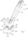
- FIGS. 1 to 9 these illustrate a preferred embodiment of the invention which comprises a fluid-dispensing apparatus 10 in the nature of a dish cleaning implement.
- the apparatus 10 is an assembly of several discrete units as will be described further below.
- proximal refers to a part of a device or system that is close to the operator in use, while the term “distal” refers to the end of the device or system that is away from the operator.
- References to the lower side of the apparatus refer to the side that faces generally towards the surface or item being cleaned when in use and references to the upper side of the apparatus refer to the side that faces generally away from the surface or item being cleaned when in use.
- the term “transverse” as used herein refers to a plane extending generally in a cross direction to the long axis of the apparatus.
- the apparatus has a handle or housing 20 which is an enclosure defining a fluid reservoir for storage of detergent (i.e. washing up liquid).
- the handle 20 has a distal end portion 22, which is received within an intermediate member 30.
- the intermediate member 30 has a distal part and a proximal part and the apparatus further comprises a working head 40 releasably mounted to the distal part of intermediate member 30.
- the end of the handle 20 remote from the working head 40 i.e. the proximal end of the handle 20
- the end of the handle 20 remote from the working head 40 i.e. the proximal end of the handle 20
- the cap 50 is removable so that the handle can be filled with detergent as needed and re-sealed using the cap 50.
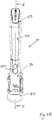
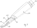
- the handle 20 has a distal end portion 22 and a main body portion 24.
- the distal end portion 22 extends from the main body portion 24, the distal end portion 22 having a smaller transverse cross-section than the main body portion 24.
- the distal end portion 22 of the handle 20 has a distal end face 26 near the distal end of the handle 20, the distal end face 26 having a dispensing aperture or outlet 27 therein.
- the handle 20 has a first shoulder 23a at the point where the distal end portion 22 extends from the main body portion 24 of the handle 20.
- the handle 20 has a second shoulder 23b slightly distal of the first shoulder.
- the intermediate member 30 has an inner tubular sleeve 37 (visible in Figure 8 ) that is shaped to receive the distal end portion 22 of the handle 20 therein.
- the intermediate member 30 has an opening 32 at its proximal end, serving as an opening to the inner tubular sleeve.
- the distal end portion 22 of the handle 20 forms a male connection member and the inner tubular sleeve of the intermediate member 30 forms a female connection member for coupling the handle 20 and intermediate member 30 with one another.
- the distal end portion 22 of the handle 20 may taper slightly in the distal direction, in which case the inner tubular sleeve of the intermediate member 30 is correspondingly internally tapered.
- the distal end portion 22 has a convexly curved upper surface 22a in its transverse cross-section and flat sides 22b extending away from the curved upper surface 22a.
- the distal end portion 22 can only be inserted in the intermediate member 30 in one orientation.
- the handle 20 has two protrusions 91 between the first and second shoulders 23a, 23b, one protrusion 91 on the upper side of the handle and one protrusion 91 on the lower side.
- the inner tubular sleeve 37 of the intermediate member 30 has corresponding recesses 38 (visible in Figure 8 ) for receiving each protrusion 91 so as to lockingly attach the intermediate member 30 to the handle 20 via a snap engagement.
- the snap engagement is strong and once the handle 20 and intermediate member 30 are assembled together during manufacture of the apparatus, they are not intended to be de-coupled from one another.
- the inner tubular sleeve terminates at its distal end in a distal end face 39, visible in Figure 4 .
- the distal end face 39 has a dispensing aperture 31 therein, which aligns with the outlet 27 of the handle 20 when assembled.
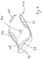
- the intermediate member 30 has an outer skirt 80 that forms the outer sides of the intermediate member 30 and which flares outwardly and distally, terminating in an oblong end wall 82 at its distal end.
- the oblong end wall 82 has side edges 81 that are curved in a plane parallel with the longitudinal axis of the apparatus.
- the distal end face 39 of the inner tubular sleeve 37 is substantially flush with the oblong end wall 82, and is joined to the outer skirt 80 by one or more bridging walls 83 to provide rigidity.
- the handle 20 has a generally circular or oval transverse cross-section but with a curvilinear upper side to give the handle an ergonomic shape.
- the handle tapers distally.
- the intermediate member 30 effectively provides a foot for the handle 20 to which the working head 40 can be mounted, the intermediate member 30 effectively extending the length of the body of the utensil when assembled.
- the opening 32 of the intermediate member 30 abuts the first shoulder 23a of the handle when assembled and the outer surface of the intermediate member 30 is flush with the outer surface of the main body portion 24 of the handle where the pieces engage with one another to give the utensil a sleek profile.
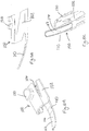
- the working head 40 includes a foam / sponge pad 41 and a base plate 44.
- the foam pad 41 is moulded, adhered or otherwise fastened to the base plate 44.
- the foam pad 41 has an abrasive foam layer 42 (useful for scouring) facing away from the base plate 44, however the working head 40 may include a single piece of non-abrasive foam without any abrasive foam layer.
- the working head 40 may have any other suitable scouring or cleaning element, such as a brush with bristles extending from the base plate 44.
- the same handle 20 and intermediate member 30, which together form a handle assembly may be used with different types of working head simply by detaching one working head and substituting it with another; in this way, the working head can be selected to suit the particular task to be carried out.
- the base plate 44 is formed of a sheet of plastics material.
- the base plate 44 comprises a generally flat or slightly curved plate that is oblong in shape.
- An upwardly extending rim 45 extends about the perimeter of the plate's upper surface along the distal end and the two long sides of the base plate 44.
- a pair of locking projections 46 extend from the rim 45 towards each other, one on each side of the base plate 44.
- the base plate 44 has a further inward facing distal projection 47 extending from the rim 45 on the distal side of the base plate 44 and an upstanding projection 48 extending from the proximal end of the base plate 44.
- the locking projections 46 are received by a corresponding pair of recessed channels 35, one on each side of the outer surface of skirt 80 of the intermediate member 30, the distal projection 47 is received in a distal end recess 33 on the distal end of the skirt 80 and the upstanding projection 48 is received in a corresponding proximal recess 34 of the skirt 80.
- the projections 46, 47, 48 are received in the corresponding recesses of the intermediate member 30 to attach the base plate 44 of the working head 40 to the intermediate member 30 via a snap engagement.
- the base plate 44 is sufficiently flexible such that the working head 40 can be detached from the intermediate member 30 by flexing the base plate 44 to disengage the distal projection 47 from recess 34 so that the base plate 44 can be slidably removed from the engagement of projections 46, 47.
- the base plate 44 Extending distally from the distal end of the base plate 44 is a scraper edge 92.
- the scraper edge 92 is intended for use in cleaning applications, such as dishware cleaning, requiring an edge for use as a tool in the dislodgement of material.
- the base plate 44 has a dispensing aperture 94. When assembled, dispensing aperture 94 of the base plate 44 aligns with the dispensing aperture 31 of the intermediate member 30 and with the outlet 27 of the handle 20 so that liquid can be dispensed from the reservoir in the handle 20 and out of the working head 40.
- the apparatus 10 further comprises a flow control member 100 for controlling the flow of fluid from the handle.
- the flow control member 100 is mounted within the intermediate member 30 and is movable between a closed position in which fluid is blocked from dispensing from the handle 20 and at least a first open position in which fluid is not blocked from dispensing from the handle 20.
- the flow control member 100 is provided as a one-piece plastic moulding having a body portion 102, a valve portion 110 and an actuator portion 120.
- the body portion 102 forms a sleeve having a throughbore with proximal and distal open ends, the body portion 102 being shaped to receive the distal end portion 22 of the handle 20 so that the flow control member 100 can be received around the distal end portion 22 when assembled.
- the actuator portion 120 comprises a protrusion that protrudes from the upper side of the body portion 102 so as to be accessible to the user when assembled.
- the intermediate member 30 has an oval shaped slot 95, configured such that the actuator portion 120 protrudes therethrough to allow the user to move the actuator portion to actuate the flow control member 100.
- the valve portion 110 comprises a tongue extending from the lower side of the body portion 102.
- the valve portion 110 has first and second apertures 112, 114 of different sizes.
- the second aperture 114 in the flow control member 100 is no larger than the apertures 27, 31 and 94.
- the flow control member 100 is movable linearly, via a sliding action, distally and proximally relative to the handle 20 and intermediate member 30, between a closed position and first and second open positions.
- the closed position as shown in Figures 1 and 8 , the solid distal end of the valve portion 110 aligns with the outlet 27 in the handle 20, such that fluid is blocked from dispensing from the handle 20.
- the actuator portion 120 can be advanced distally by the user to move the flow control member 100 to the first open position, wherein the first aperture 112 aligns with the outlet 27 in the handle 20, such that fluid can flow out of the handle, through aperture 112, through dispensing aperture 31 in the intermediate member and out of dispensing aperture 94 of the working head 40.
- the actuator portion 120 can be advanced distally from the first open position to the second open position, wherein the second aperture 114 aligns with the outlet 27 in the handle 20, such that fluid can flow out of the handle, through aperture 114, through dispensing aperture 31 and out of dispensing aperture 94 of the working head 40.
- the second aperture 114 is larger than the first aperture 112
- the second open position corresponds to a high flow rate configuration
- the first open position corresponds to a low flow rate configuration. This allows the user to select between first and second discrete flow control configurations. Further apertures of differing sizes could of course be provided in the valve portion to provide further discrete flow control configurations.
- the flow control member 100 has a detent 104 protruding upwardly from the inner surface of the lower side of the body portion 102.
- the lower surface of the distal end portion 22 of the handle has first, second and third detent recesses 97a, 97b, 97c for receiving the detent 104 to maintain the flow control member 100 in the closed, first open or second position, as selected by the operator.
- the detent recesses 97a, 97b, 97c are arranged in a line parallel with the longitudinal axis of the handle.
- the flow control member When the detent 104 is seated in the second detent recess 97b, the flow control member is in the first open position. When the detent 104 is seated in the third detent recess 97c, the flow control member is in the second open position. A small force is required to be applied by the operator to the actuator portion 120 to move detent 104 from one recess to an adjacent recess and therefore to move the flow control member between the discrete positions.
- the intermediate member 30 has three indication markers 96a, 96b, 96c on its outer surface that are visible to the user to indicate the three discrete flow control configurations that the flow control member 100 can be moved between.
- the indication markers 96a, 96b, 96c are raised from the outer surface of the intermediate member 30 so that the operator can feel the indication markers, however it will be understood that the indication markers need not be raised, but may be flush with the outer surface or indented in the outer surface of the intermediate member 30.
- the indication markers 96a, 96b, 96c are circular marks, arranged in a line in the proximal to distal direction, each indication marker being larger than the marker proximal to it.
- the actuator portion 120 When the actuator portion 120 is aligned with the first indication marker 96a, this indicates to the operator that the flow control member is in the closed position. When the actuator portion 120 is aligned with the second indication marker 96b, this indicates to the operator that the flow control member is in the first open position (i.e. the low flow configuration). When the actuator portion 120 is aligned with the third indication marker 96c, this indicates to the operator that the flow control member is in the second open position (i.e. the high flow configuration).
- the cap 50 attaches to the handle 20 via a bayonet fitting. This ensures that the cap 50, whose upper and lower sides are not symmetrical with one another, attaches to the handle 20 in the desired orientation relative to the handle 20.
- the cap 50 has two male bayonet protrusions 52 protruding inwardly from the opposite sides of the inner rim of the cap.
- the proximal end of the handle 20 has two corresponding female bayonet receivers 54 that engage with the bayonet protrusions 52 on the cap to secure the cap to the handle.
- the cap 50 may of course attach to the handle 20 using any other suitable attachment means whereby the cap 50 is releasably and sealably attachable to the handle 20, for example by means of threaded engagement.
- the apparatus can be stored between uses with the flow control member 100 in the closed position, so as to prevent leakage of the fluid from the reservoir.
- the user can move the actuator portion 120 of the flow control member 100 to the first or second open positions, depending on the level of flow of detergent fluid desired. Once the flow control member 100 is in the first or second open position, fluid can flow out of the outlet 27 in the handle, through the selected aperture 112, 114 in the flow control member 100, through the dispensing apertures 31, 94, to dispense fluid from the working head.
- the flow control member 100 is movable linearly between the closed and open positions.
- the flow control member 100 need not move linearly, but could be configured to move rotatably between the positions.
- the handle 20 and intermediate member 30 are preferably injection moulded. During manufacture of the apparatus, after the units of the assembly have been made, they are assembled together as described above. Since the intermediate member 30 is a separate piece from the handle 20, the intermediate member 30 can be selected from a range of different shapes and/or sizes to suit different uses. For example, the intermediate member illustrated in Figures 1 to 9 is suitable for general washing of dishes however a narrower intermediate member 30 for receipt within bottle necks could be used in the assembly so that the apparatus could be used as a bottle cleaning device.
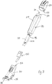
- the apparatus need not include a flow control member 100.
- a fluid dispensing apparatus 10' is shown which is similar to that of Figures 1 to 9 , but which does not include a flow control member 100.
- the assembly of Figure 10 has a handle 20 with distal end portion 22 which is received within an intermediate member 30, the assembly further comprising a working head 40 which attaches to the intermediate member 30.
- the device therefore has the advantage of being made from a modular assembly of a hollow handle 20 for storage of the fluid and an initially separate intermediate member 30 which assembles thereto and which can be selected during manufacture from two or more intermediate members of different shapes and/or sizes to suit different uses.
- Suitable means other than as shown in Figures 1 to 9 may be used for releasably latching the working head 40 to the intermediate member 30.
Landscapes
- Devices For Dispensing Beverages (AREA)
- Washing And Drying Of Tableware (AREA)
- Containers And Packaging Bodies Having A Special Means To Remove Contents (AREA)
Applications Claiming Priority (1)
| Application Number | Priority Date | Filing Date | Title |
|---|---|---|---|
| GB1411689.1A GB2526886B (en) | 2014-07-01 | 2014-07-01 | Improvements to fluid-dispensing apparatus |
Publications (2)
| Publication Number | Publication Date |
|---|---|
| EP2962615A1 EP2962615A1 (en) | 2016-01-06 |
| EP2962615B1 true EP2962615B1 (en) | 2017-03-08 |
Family
ID=51410430
Family Applications (1)
| Application Number | Title | Priority Date | Filing Date |
|---|---|---|---|
| EP15174492.7A Active EP2962615B1 (en) | 2014-07-01 | 2015-06-30 | Improvements to fluid-dispensing apparatus |
Country Status (6)
| Country | Link |
|---|---|
| US (1) | US9526326B2 (enExample) |
| EP (1) | EP2962615B1 (enExample) |
| JP (1) | JP6670050B2 (enExample) |
| AU (1) | AU2015203594B2 (enExample) |
| ES (1) | ES2621265T3 (enExample) |
| GB (1) | GB2526886B (enExample) |
Families Citing this family (12)
| Publication number | Priority date | Publication date | Assignee | Title |
|---|---|---|---|---|
| USD815439S1 (en) * | 2015-03-06 | 2018-04-17 | The Libman Company | Soap dispenser |
| USD828969S1 (en) * | 2016-10-14 | 2018-09-18 | Michael Robert Brady | Dish cleaner with suction cup |
| USD825931S1 (en) | 2017-02-10 | 2018-08-21 | FC Brands Ltd. | Foaming brush |
| USD854269S1 (en) * | 2018-04-20 | 2019-07-16 | 3M Innovative Properties Company | Cleaning tool |
| DK201970154A1 (en) * | 2019-03-06 | 2020-09-08 | Imbox Shoecare As | After treatment system |
| AT522236B1 (de) * | 2019-03-13 | 2022-02-15 | Georg Hagleitner Hans | Spenderset mit einer Ausgabevorrichtung und mindestens einem ein pumpfähiges Medium enthaltenden Behälter |
| US10631625B1 (en) | 2019-04-01 | 2020-04-28 | Hala F.H.Y. Alhajji | Vibrating dispensing hairbrush |
| USD948877S1 (en) * | 2019-10-17 | 2022-04-19 | Magellan Home-Goods, Ltd. | Grill brush |
| CN112137533B (zh) * | 2020-10-22 | 2025-06-13 | 北京石头世纪科技股份有限公司 | 一种地面清洁装置 |
| CN112137532B (zh) * | 2020-10-22 | 2025-10-24 | 北京石头世纪科技股份有限公司 | 一种水箱组件 |
| US11944186B2 (en) | 2021-03-12 | 2024-04-02 | Burns Brothers LLC | Flexible cleaner |
| USD970224S1 (en) * | 2022-08-10 | 2022-11-22 | Xiaoqun Luo | Dish brush handle |
Family Cites Families (42)
| Publication number | Priority date | Publication date | Assignee | Title |
|---|---|---|---|---|
| US729515A (en) | 1902-10-21 | 1903-05-26 | Alfred Steele | Brush. |
| GB141183A (en) | 1919-03-31 | 1920-04-15 | Justine Breeden Mcnamara | An improved device for washing and cleaning crockery or other articles or bodies |
| US2823401A (en) * | 1954-01-15 | 1958-02-18 | O'higgins Michael | Tooth brush |
| US3653779A (en) | 1970-03-30 | 1972-04-04 | Gilbert Schwartzman | Disc valve for applicator |
| US3661468A (en) | 1970-05-25 | 1972-05-09 | Gilbert Schwartzman | Fluid applicator having wine-cup shaped valve assembly |
| IT970618B (it) | 1971-12-03 | 1974-04-20 | Garcia Mila Palaudarias J | Dispositivo automatico per tappare recipienti contenenti liquidi a pressione atmosferica |
| US4053242A (en) | 1976-03-18 | 1977-10-11 | The Procter & Gamble Company | Disposable product applicator and dispensing package therefor |
| US4077725A (en) * | 1976-05-27 | 1978-03-07 | Slautterback Ernest G | Shoe polish applicator |
| US4135831A (en) * | 1977-01-14 | 1979-01-23 | Jack Reitknecht | Laminated fountain toothbrush with barrier |
| USD267282S (en) | 1980-10-09 | 1982-12-14 | Abbott Laboratories | Sponge applicator, or the like |
| US4692047A (en) * | 1983-04-20 | 1987-09-08 | Sasuke Endo | Brush for applying material in liquid or emulsion form |
| GB2160092A (en) * | 1984-05-08 | 1985-12-18 | Alphaplan Ltd | Cleaning device |
| GB2159698A (en) | 1984-05-08 | 1985-12-11 | Alphaplan Ltd | Cleaning device |
| US5120148A (en) | 1986-03-10 | 1992-06-09 | The West Company, Incorporated | Applicator assembly |
| DE3700113A1 (de) * | 1987-01-03 | 1988-07-14 | Rothweiler Gmbh & Co Kg Geb | Handbuerste |
| JPS63143209U (enExample) | 1987-03-09 | 1988-09-21 | ||
| USD306924S (en) | 1987-04-23 | 1990-03-27 | Shapton Robert W | Fluid dispensing sponge mop for use on a car |
| GB9319686D0 (en) * | 1993-09-23 | 1993-11-10 | Taghavi Said | Toothbrush with toothpaste reservoir and bristle adapters |
| US5509744A (en) * | 1995-06-23 | 1996-04-23 | Frazier; Thomas G. | Liquid applicator with slide ring activator |
| USD387704S (en) | 1996-09-27 | 1997-12-16 | The Libman Company | Liquid-dispensing scrub brush |
| USD389625S (en) | 1996-11-12 | 1998-01-20 | Rubbermaid Incorporated | Sponge mop |
| WO1999063857A1 (en) | 1998-06-09 | 1999-12-16 | Rabatic Miso | Tooth-brush with container for tooth-paste |
| GB2363977B (en) * | 2000-06-20 | 2003-07-02 | London Oil Refining Company Lt | A toilet cleaning apparatus |
| AU2001287926A1 (en) * | 2000-10-27 | 2002-05-06 | Vale Mill (Rochdale) Ltd | Cleaning utensils |
| GB2369560B (en) * | 2000-11-24 | 2002-12-18 | Easy Do Products Ltd | Improvements to implements for cleaning polishing or sanding |
| US20020186996A1 (en) * | 2001-06-12 | 2002-12-12 | Aramark Corporation | Dispenser |
| BE1014287A6 (nl) * | 2001-07-06 | 2003-08-05 | Waak Beschutte Werkplaats Vzw | Reinigingstoestel alsmede onderdeel voor het vormen van dergelijk reinigingstoestel. |
| GB2395680B (en) | 2002-11-28 | 2004-10-27 | Easy Do Products Ltd | Improvements to handheld utensils for cleaning |
| US7146676B2 (en) | 2003-09-16 | 2006-12-12 | 3M Innovative Properties Company | Cleaning device with disposable pad |
| US20050147461A1 (en) * | 2003-09-22 | 2005-07-07 | Glover J. S. | Dispensing brush |
| USD511626S1 (en) | 2003-10-14 | 2005-11-22 | Hayco Manufacturing Limited | Handle with base for cleaning implement |
| US20070212161A1 (en) * | 2006-03-08 | 2007-09-13 | Carlson Karen A | Pool tile cleaning device and method |
| US7771135B2 (en) * | 2006-03-23 | 2010-08-10 | The Libman Company | Scrubber and cleaning fluid dispenser assembly |
| WO2007137354A1 (en) * | 2006-06-01 | 2007-12-06 | The Decor Corporation Pty Ltd | A brush or mop or like tool |
| US8262307B1 (en) * | 2006-06-22 | 2012-09-11 | Cross Thomas E | Attachable condiment applicators and kit therefor |
| USD549412S1 (en) | 2006-10-10 | 2007-08-21 | Conopco, Inc. | Cleansing implement |
| USD558417S1 (en) | 2007-01-18 | 2007-12-25 | The Libman Company | Soap dispenser |
| KR200450995Y1 (ko) * | 2008-08-26 | 2010-11-16 | (주)연우 | 펜슬형 화장품용기 |
| US8550738B2 (en) * | 2008-08-28 | 2013-10-08 | Hct Asia Ltd | Flow-through dispenser with helical actuation |
| US7677827B1 (en) * | 2008-09-29 | 2010-03-16 | Oleg Manukian | Toothbrush with toothpaste dispenser |
| USD606269S1 (en) | 2008-10-04 | 2009-12-15 | Easy-Do Products Limited | Hand-held cleaning utensil with removable sponge head |
| US7717635B1 (en) * | 2008-11-12 | 2010-05-18 | Jennifer Schmidig | Liquid dispensing brush |
-
2014
- 2014-07-01 GB GB1411689.1A patent/GB2526886B/en active Active
-
2015
- 2015-06-26 JP JP2015129315A patent/JP6670050B2/ja not_active Expired - Fee Related
- 2015-06-26 AU AU2015203594A patent/AU2015203594B2/en active Active
- 2015-06-30 US US14/788,197 patent/US9526326B2/en active Active
- 2015-06-30 EP EP15174492.7A patent/EP2962615B1/en active Active
- 2015-06-30 ES ES15174492.7T patent/ES2621265T3/es active Active
Also Published As
| Publication number | Publication date |
|---|---|
| AU2015203594A1 (en) | 2016-01-21 |
| US20160000213A1 (en) | 2016-01-07 |
| GB2526886A (en) | 2015-12-09 |
| AU2015203594B2 (en) | 2019-01-17 |
| ES2621265T3 (es) | 2017-07-03 |
| EP2962615A1 (en) | 2016-01-06 |
| GB201411689D0 (en) | 2014-08-13 |
| US9526326B2 (en) | 2016-12-27 |
| JP6670050B2 (ja) | 2020-03-18 |
| JP2016013435A (ja) | 2016-01-28 |
| GB2526886B (en) | 2016-05-11 |
Similar Documents
| Publication | Publication Date | Title |
|---|---|---|
| EP2962615B1 (en) | Improvements to fluid-dispensing apparatus | |
| EP2330962B1 (en) | Plural nozzle cleaning implement | |
| US7172099B2 (en) | Fluid delivery mechanism | |
| AU2006285437B2 (en) | Surface cleaning device with liquid dispenser | |
| EP3244787B1 (en) | Tool assembly comprising universal handle and interchangeable tool heads | |
| US6817801B1 (en) | Automotive interior liquid applicator | |
| US20040105715A1 (en) | Cleaning utensils | |
| EP2811888A1 (en) | Double sided spray mop | |
| EP2632317A1 (en) | Cleaning device having plural and customizable cleaning surfaces | |
| US20200315406A1 (en) | Soap Dispenser Showerhead | |
| AU2016348623B2 (en) | Bucket | |
| KR20170010804A (ko) | 유체 분배 세정 도구 | |
| EP1343407B1 (en) | Improvements to implements for cleaning, polishing or sanding | |
| US20170172380A1 (en) | Dispensing pad cleaner | |
| US9861246B2 (en) | Unitary cleaning device having onboard replaceable cleaning pad and onboard replaceable cleaning solution | |
| US20060133886A1 (en) | Shampooing brush | |
| US7004663B1 (en) | Bathroom cleaning device | |
| TWI526189B (zh) | Wet cleaning tool | |
| GB2518854A (en) | A nozzle head | |
| WO2012152774A1 (en) | Dispenser, especially for liquid hygiene agents | |
| HK1130639A1 (en) | A brush or mop or like tool | |
| HK1130639B (en) | A brush or mop or like tool |
Legal Events
| Date | Code | Title | Description |
|---|---|---|---|
| PUAI | Public reference made under article 153(3) epc to a published international application that has entered the european phase |
Free format text: ORIGINAL CODE: 0009012 |
|
| AK | Designated contracting states |
Kind code of ref document: A1 Designated state(s): AL AT BE BG CH CY CZ DE DK EE ES FI FR GB GR HR HU IE IS IT LI LT LU LV MC MK MT NL NO PL PT RO RS SE SI SK SM TR |
|
| AX | Request for extension of the european patent |
Extension state: BA ME |
|
| 17P | Request for examination filed |
Effective date: 20160201 |
|
| RBV | Designated contracting states (corrected) |
Designated state(s): AL AT BE BG CH CY CZ DE DK EE ES FI FR GB GR HR HU IE IS IT LI LT LU LV MC MK MT NL NO PL PT RO RS SE SI SK SM TR |
|
| GRAP | Despatch of communication of intention to grant a patent |
Free format text: ORIGINAL CODE: EPIDOSNIGR1 |
|
| RIC1 | Information provided on ipc code assigned before grant |
Ipc: A47L 23/05 20060101ALI20160627BHEP Ipc: A47L 13/22 20060101AFI20160627BHEP Ipc: A46B 9/00 20060101ALI20160627BHEP Ipc: A46B 11/00 20060101ALI20160627BHEP |
|
| INTG | Intention to grant announced |
Effective date: 20160715 |
|
| RIN1 | Information on inventor provided before grant (corrected) |
Inventor name: NEUMANN, DANIEL Inventor name: NEUMANN, PAUL |
|
| GRAJ | Information related to disapproval of communication of intention to grant by the applicant or resumption of examination proceedings by the epo deleted |
Free format text: ORIGINAL CODE: EPIDOSDIGR1 |
|
| GRAS | Grant fee paid |
Free format text: ORIGINAL CODE: EPIDOSNIGR3 |
|
| GRAP | Despatch of communication of intention to grant a patent |
Free format text: ORIGINAL CODE: EPIDOSNIGR1 |
|
| INTC | Intention to grant announced (deleted) | ||
| RBV | Designated contracting states (corrected) |
Designated state(s): AL AT BE BG CH CY CZ DE DK EE ES FI FR GR HR HU IE IS IT LI LT LU LV MC MK MT NL NO PL PT RO RS SE SI SK SM TR |
|
| GRAJ | Information related to disapproval of communication of intention to grant by the applicant or resumption of examination proceedings by the epo deleted |
Free format text: ORIGINAL CODE: EPIDOSDIGR1 |
|
| GRAL | Information related to payment of fee for publishing/printing deleted |
Free format text: ORIGINAL CODE: EPIDOSDIGR3 |
|
| INTG | Intention to grant announced |
Effective date: 20161215 |
|
| GRAP | Despatch of communication of intention to grant a patent |
Free format text: ORIGINAL CODE: EPIDOSNIGR1 |
|
| GRAA | (expected) grant |
Free format text: ORIGINAL CODE: 0009210 |
|
| INTC | Intention to grant announced (deleted) | ||
| INTG | Intention to grant announced |
Effective date: 20170118 |
|
| AK | Designated contracting states |
Kind code of ref document: B1 Designated state(s): AL AT BE BG CH CY CZ DE DK EE ES FI FR GR HR HU IE IS IT LI LT LU LV MC MK MT NL NO PL PT RO RS SE SI SK SM TR |
|
| REG | Reference to a national code |
Ref country code: CH Ref legal event code: EP Ref country code: AT Ref legal event code: REF Ref document number: 872763 Country of ref document: AT Kind code of ref document: T Effective date: 20170315 |
|
| REG | Reference to a national code |
Ref country code: IE Ref legal event code: FG4D |
|
| REG | Reference to a national code |
Ref country code: SE Ref legal event code: TRGR |
|
| REG | Reference to a national code |
Ref country code: NL Ref legal event code: FP |
|
| REG | Reference to a national code |
Ref country code: DE Ref legal event code: R096 Ref document number: 602015001727 Country of ref document: DE |
|
| REG | Reference to a national code |
Ref country code: FR Ref legal event code: PLFP Year of fee payment: 3 |
|
| REG | Reference to a national code |
Ref country code: ES Ref legal event code: FG2A Ref document number: 2621265 Country of ref document: ES Kind code of ref document: T3 Effective date: 20170703 |
|
| REG | Reference to a national code |
Ref country code: LT Ref legal event code: MG4D |
|
| PG25 | Lapsed in a contracting state [announced via postgrant information from national office to epo] |
Ref country code: NO Free format text: LAPSE BECAUSE OF FAILURE TO SUBMIT A TRANSLATION OF THE DESCRIPTION OR TO PAY THE FEE WITHIN THE PRESCRIBED TIME-LIMIT Effective date: 20170608 Ref country code: FI Free format text: LAPSE BECAUSE OF FAILURE TO SUBMIT A TRANSLATION OF THE DESCRIPTION OR TO PAY THE FEE WITHIN THE PRESCRIBED TIME-LIMIT Effective date: 20170308 Ref country code: LT Free format text: LAPSE BECAUSE OF FAILURE TO SUBMIT A TRANSLATION OF THE DESCRIPTION OR TO PAY THE FEE WITHIN THE PRESCRIBED TIME-LIMIT Effective date: 20170308 Ref country code: GR Free format text: LAPSE BECAUSE OF FAILURE TO SUBMIT A TRANSLATION OF THE DESCRIPTION OR TO PAY THE FEE WITHIN THE PRESCRIBED TIME-LIMIT Effective date: 20170609 Ref country code: HR Free format text: LAPSE BECAUSE OF FAILURE TO SUBMIT A TRANSLATION OF THE DESCRIPTION OR TO PAY THE FEE WITHIN THE PRESCRIBED TIME-LIMIT Effective date: 20170308 |
|
| REG | Reference to a national code |
Ref country code: AT Ref legal event code: MK05 Ref document number: 872763 Country of ref document: AT Kind code of ref document: T Effective date: 20170308 |
|
| PG25 | Lapsed in a contracting state [announced via postgrant information from national office to epo] |
Ref country code: RS Free format text: LAPSE BECAUSE OF FAILURE TO SUBMIT A TRANSLATION OF THE DESCRIPTION OR TO PAY THE FEE WITHIN THE PRESCRIBED TIME-LIMIT Effective date: 20170308 Ref country code: LV Free format text: LAPSE BECAUSE OF FAILURE TO SUBMIT A TRANSLATION OF THE DESCRIPTION OR TO PAY THE FEE WITHIN THE PRESCRIBED TIME-LIMIT Effective date: 20170308 Ref country code: BG Free format text: LAPSE BECAUSE OF FAILURE TO SUBMIT A TRANSLATION OF THE DESCRIPTION OR TO PAY THE FEE WITHIN THE PRESCRIBED TIME-LIMIT Effective date: 20170608 |
|
| PG25 | Lapsed in a contracting state [announced via postgrant information from national office to epo] |
Ref country code: AT Free format text: LAPSE BECAUSE OF FAILURE TO SUBMIT A TRANSLATION OF THE DESCRIPTION OR TO PAY THE FEE WITHIN THE PRESCRIBED TIME-LIMIT Effective date: 20170308 Ref country code: RO Free format text: LAPSE BECAUSE OF FAILURE TO SUBMIT A TRANSLATION OF THE DESCRIPTION OR TO PAY THE FEE WITHIN THE PRESCRIBED TIME-LIMIT Effective date: 20170308 Ref country code: EE Free format text: LAPSE BECAUSE OF FAILURE TO SUBMIT A TRANSLATION OF THE DESCRIPTION OR TO PAY THE FEE WITHIN THE PRESCRIBED TIME-LIMIT Effective date: 20170308 Ref country code: SK Free format text: LAPSE BECAUSE OF FAILURE TO SUBMIT A TRANSLATION OF THE DESCRIPTION OR TO PAY THE FEE WITHIN THE PRESCRIBED TIME-LIMIT Effective date: 20170308 Ref country code: CZ Free format text: LAPSE BECAUSE OF FAILURE TO SUBMIT A TRANSLATION OF THE DESCRIPTION OR TO PAY THE FEE WITHIN THE PRESCRIBED TIME-LIMIT Effective date: 20170308 |
|
| PG25 | Lapsed in a contracting state [announced via postgrant information from national office to epo] |
Ref country code: PL Free format text: LAPSE BECAUSE OF FAILURE TO SUBMIT A TRANSLATION OF THE DESCRIPTION OR TO PAY THE FEE WITHIN THE PRESCRIBED TIME-LIMIT Effective date: 20170308 Ref country code: SM Free format text: LAPSE BECAUSE OF FAILURE TO SUBMIT A TRANSLATION OF THE DESCRIPTION OR TO PAY THE FEE WITHIN THE PRESCRIBED TIME-LIMIT Effective date: 20170308 Ref country code: PT Free format text: LAPSE BECAUSE OF FAILURE TO SUBMIT A TRANSLATION OF THE DESCRIPTION OR TO PAY THE FEE WITHIN THE PRESCRIBED TIME-LIMIT Effective date: 20170710 Ref country code: IS Free format text: LAPSE BECAUSE OF FAILURE TO SUBMIT A TRANSLATION OF THE DESCRIPTION OR TO PAY THE FEE WITHIN THE PRESCRIBED TIME-LIMIT Effective date: 20170708 |
|
| REG | Reference to a national code |
Ref country code: DE Ref legal event code: R097 Ref document number: 602015001727 Country of ref document: DE |
|
| PLBE | No opposition filed within time limit |
Free format text: ORIGINAL CODE: 0009261 |
|
| STAA | Information on the status of an ep patent application or granted ep patent |
Free format text: STATUS: NO OPPOSITION FILED WITHIN TIME LIMIT |
|
| PG25 | Lapsed in a contracting state [announced via postgrant information from national office to epo] |
Ref country code: DK Free format text: LAPSE BECAUSE OF FAILURE TO SUBMIT A TRANSLATION OF THE DESCRIPTION OR TO PAY THE FEE WITHIN THE PRESCRIBED TIME-LIMIT Effective date: 20170308 Ref country code: MC Free format text: LAPSE BECAUSE OF FAILURE TO SUBMIT A TRANSLATION OF THE DESCRIPTION OR TO PAY THE FEE WITHIN THE PRESCRIBED TIME-LIMIT Effective date: 20170308 |
|
| 26N | No opposition filed |
Effective date: 20171211 |
|
| PG25 | Lapsed in a contracting state [announced via postgrant information from national office to epo] |
Ref country code: SI Free format text: LAPSE BECAUSE OF FAILURE TO SUBMIT A TRANSLATION OF THE DESCRIPTION OR TO PAY THE FEE WITHIN THE PRESCRIBED TIME-LIMIT Effective date: 20170308 |
|
| PG25 | Lapsed in a contracting state [announced via postgrant information from national office to epo] |
Ref country code: LU Free format text: LAPSE BECAUSE OF NON-PAYMENT OF DUE FEES Effective date: 20170630 |
|
| REG | Reference to a national code |
Ref country code: BE Ref legal event code: MM Effective date: 20170630 |
|
| REG | Reference to a national code |
Ref country code: FR Ref legal event code: PLFP Year of fee payment: 4 |
|
| PG25 | Lapsed in a contracting state [announced via postgrant information from national office to epo] |
Ref country code: BE Free format text: LAPSE BECAUSE OF NON-PAYMENT OF DUE FEES Effective date: 20170630 |
|
| PG25 | Lapsed in a contracting state [announced via postgrant information from national office to epo] |
Ref country code: MT Free format text: LAPSE BECAUSE OF NON-PAYMENT OF DUE FEES Effective date: 20170630 |
|
| REG | Reference to a national code |
Ref country code: CH Ref legal event code: PL |
|
| PG25 | Lapsed in a contracting state [announced via postgrant information from national office to epo] |
Ref country code: LI Free format text: LAPSE BECAUSE OF NON-PAYMENT OF DUE FEES Effective date: 20180630 Ref country code: CH Free format text: LAPSE BECAUSE OF NON-PAYMENT OF DUE FEES Effective date: 20180630 |
|
| PG25 | Lapsed in a contracting state [announced via postgrant information from national office to epo] |
Ref country code: HU Free format text: LAPSE BECAUSE OF FAILURE TO SUBMIT A TRANSLATION OF THE DESCRIPTION OR TO PAY THE FEE WITHIN THE PRESCRIBED TIME-LIMIT; INVALID AB INITIO Effective date: 20150630 |
|
| PG25 | Lapsed in a contracting state [announced via postgrant information from national office to epo] |
Ref country code: CY Free format text: LAPSE BECAUSE OF FAILURE TO SUBMIT A TRANSLATION OF THE DESCRIPTION OR TO PAY THE FEE WITHIN THE PRESCRIBED TIME-LIMIT Effective date: 20170308 |
|
| PG25 | Lapsed in a contracting state [announced via postgrant information from national office to epo] |
Ref country code: MK Free format text: LAPSE BECAUSE OF FAILURE TO SUBMIT A TRANSLATION OF THE DESCRIPTION OR TO PAY THE FEE WITHIN THE PRESCRIBED TIME-LIMIT Effective date: 20170308 |
|
| PG25 | Lapsed in a contracting state [announced via postgrant information from national office to epo] |
Ref country code: TR Free format text: LAPSE BECAUSE OF FAILURE TO SUBMIT A TRANSLATION OF THE DESCRIPTION OR TO PAY THE FEE WITHIN THE PRESCRIBED TIME-LIMIT Effective date: 20170308 |
|
| PG25 | Lapsed in a contracting state [announced via postgrant information from national office to epo] |
Ref country code: AL Free format text: LAPSE BECAUSE OF FAILURE TO SUBMIT A TRANSLATION OF THE DESCRIPTION OR TO PAY THE FEE WITHIN THE PRESCRIBED TIME-LIMIT Effective date: 20170308 |
|
| REG | Reference to a national code |
Ref country code: DE Ref legal event code: R081 Ref document number: 602015001727 Country of ref document: DE Owner name: LIBMAN BRANDS UK LTD., WELLINGBOROUGH, GB Free format text: FORMER OWNER: EASY-DO PRODUCTS LTD., LONDON, GB |
|
| REG | Reference to a national code |
Ref country code: NL Ref legal event code: HC Owner name: LIBMAN BRANDS UK LTD.; GB Free format text: DETAILS ASSIGNMENT: CHANGE OF OWNER(S), CHANGE OF OWNER(S) NAME; FORMER OWNER NAME: EASY-DO PRODUCTS LIMITED Effective date: 20220726 |
|
| REG | Reference to a national code |
Ref country code: ES Ref legal event code: PC2A Owner name: LIBMAN BRANDS UK LTD. Effective date: 20221205 |
|
| P01 | Opt-out of the competence of the unified patent court (upc) registered |
Effective date: 20230515 |
|
| PGFP | Annual fee paid to national office [announced via postgrant information from national office to epo] |
Ref country code: SE Payment date: 20250306 Year of fee payment: 11 |
|
| PGFP | Annual fee paid to national office [announced via postgrant information from national office to epo] |
Ref country code: DE Payment date: 20250626 Year of fee payment: 11 |
|
| PGFP | Annual fee paid to national office [announced via postgrant information from national office to epo] |
Ref country code: NL Payment date: 20250624 Year of fee payment: 11 |
|
| PGFP | Annual fee paid to national office [announced via postgrant information from national office to epo] |
Ref country code: FR Payment date: 20250623 Year of fee payment: 11 |
|
| PGFP | Annual fee paid to national office [announced via postgrant information from national office to epo] |
Ref country code: IE Payment date: 20250623 Year of fee payment: 11 |
|
| PGFP | Annual fee paid to national office [announced via postgrant information from national office to epo] |
Ref country code: ES Payment date: 20250714 Year of fee payment: 11 |
|
| PGFP | Annual fee paid to national office [announced via postgrant information from national office to epo] |
Ref country code: IT Payment date: 20250619 Year of fee payment: 11 |