EP2962019B1 - Ventil, insbesondere für eine wärmekraftmaschine - Google Patents
Ventil, insbesondere für eine wärmekraftmaschine Download PDFInfo
- Publication number
- EP2962019B1 EP2962019B1 EP14713160.1A EP14713160A EP2962019B1 EP 2962019 B1 EP2962019 B1 EP 2962019B1 EP 14713160 A EP14713160 A EP 14713160A EP 2962019 B1 EP2962019 B1 EP 2962019B1
- Authority
- EP
- European Patent Office
- Prior art keywords
- flap
- intermediate component
- region
- wall
- valve
- Prior art date
- Legal status (The legal status is an assumption and is not a legal conclusion. Google has not performed a legal analysis and makes no representation as to the accuracy of the status listed.)
- Not-in-force
Links
Images

Classifications
-
- F—MECHANICAL ENGINEERING; LIGHTING; HEATING; WEAPONS; BLASTING
- F16—ENGINEERING ELEMENTS AND UNITS; GENERAL MEASURES FOR PRODUCING AND MAINTAINING EFFECTIVE FUNCTIONING OF MACHINES OR INSTALLATIONS; THERMAL INSULATION IN GENERAL
- F16K—VALVES; TAPS; COCKS; ACTUATING-FLOATS; DEVICES FOR VENTING OR AERATING
- F16K1/00—Lift valves or globe valves, i.e. cut-off apparatus with closure members having at least a component of their opening and closing motion perpendicular to the closing faces
- F16K1/16—Lift valves or globe valves, i.e. cut-off apparatus with closure members having at least a component of their opening and closing motion perpendicular to the closing faces with pivoted closure-members
- F16K1/18—Lift valves or globe valves, i.e. cut-off apparatus with closure members having at least a component of their opening and closing motion perpendicular to the closing faces with pivoted closure-members with pivoted discs or flaps
- F16K1/20—Lift valves or globe valves, i.e. cut-off apparatus with closure members having at least a component of their opening and closing motion perpendicular to the closing faces with pivoted closure-members with pivoted discs or flaps with axis of rotation arranged externally of valve member
- F16K1/2042—Special features or arrangements of the sealing
-
- F—MECHANICAL ENGINEERING; LIGHTING; HEATING; WEAPONS; BLASTING
- F02—COMBUSTION ENGINES; HOT-GAS OR COMBUSTION-PRODUCT ENGINE PLANTS
- F02M—SUPPLYING COMBUSTION ENGINES IN GENERAL WITH COMBUSTIBLE MIXTURES OR CONSTITUENTS THEREOF
- F02M26/00—Engine-pertinent apparatus for adding exhaust gases to combustion-air, main fuel or fuel-air mixture, e.g. by exhaust gas recirculation [EGR] systems
- F02M26/13—Arrangement or layout of EGR passages, e.g. in relation to specific engine parts or for incorporation of accessories
- F02M26/14—Arrangement or layout of EGR passages, e.g. in relation to specific engine parts or for incorporation of accessories in relation to the exhaust system
- F02M26/16—Arrangement or layout of EGR passages, e.g. in relation to specific engine parts or for incorporation of accessories in relation to the exhaust system with EGR valves located at or near the connection to the exhaust system
-
- F—MECHANICAL ENGINEERING; LIGHTING; HEATING; WEAPONS; BLASTING
- F02—COMBUSTION ENGINES; HOT-GAS OR COMBUSTION-PRODUCT ENGINE PLANTS
- F02M—SUPPLYING COMBUSTION ENGINES IN GENERAL WITH COMBUSTIBLE MIXTURES OR CONSTITUENTS THEREOF
- F02M26/00—Engine-pertinent apparatus for adding exhaust gases to combustion-air, main fuel or fuel-air mixture, e.g. by exhaust gas recirculation [EGR] systems
- F02M26/51—EGR valves combined with other devices, e.g. with intake valves or compressors
-
- F—MECHANICAL ENGINEERING; LIGHTING; HEATING; WEAPONS; BLASTING
- F02—COMBUSTION ENGINES; HOT-GAS OR COMBUSTION-PRODUCT ENGINE PLANTS
- F02M—SUPPLYING COMBUSTION ENGINES IN GENERAL WITH COMBUSTIBLE MIXTURES OR CONSTITUENTS THEREOF
- F02M26/00—Engine-pertinent apparatus for adding exhaust gases to combustion-air, main fuel or fuel-air mixture, e.g. by exhaust gas recirculation [EGR] systems
- F02M26/65—Constructional details of EGR valves
- F02M26/70—Flap valves; Rotary valves; Sliding valves; Resilient valves
-
- F—MECHANICAL ENGINEERING; LIGHTING; HEATING; WEAPONS; BLASTING
- F16—ENGINEERING ELEMENTS AND UNITS; GENERAL MEASURES FOR PRODUCING AND MAINTAINING EFFECTIVE FUNCTIONING OF MACHINES OR INSTALLATIONS; THERMAL INSULATION IN GENERAL
- F16K—VALVES; TAPS; COCKS; ACTUATING-FLOATS; DEVICES FOR VENTING OR AERATING
- F16K27/00—Construction of housing; Use of materials therefor
- F16K27/02—Construction of housing; Use of materials therefor of lift valves
- F16K27/0209—Check valves or pivoted valves
- F16K27/0227—Check valves or pivoted valves with the valve members swinging around an axis located at the edge of or outside the valve member
-
- F—MECHANICAL ENGINEERING; LIGHTING; HEATING; WEAPONS; BLASTING
- F02—COMBUSTION ENGINES; HOT-GAS OR COMBUSTION-PRODUCT ENGINE PLANTS
- F02D—CONTROLLING COMBUSTION ENGINES
- F02D9/00—Controlling engines by throttling air or fuel-and-air induction conduits or exhaust conduits
- F02D9/04—Controlling engines by throttling air or fuel-and-air induction conduits or exhaust conduits concerning exhaust conduits
-
- F—MECHANICAL ENGINEERING; LIGHTING; HEATING; WEAPONS; BLASTING
- F02—COMBUSTION ENGINES; HOT-GAS OR COMBUSTION-PRODUCT ENGINE PLANTS
- F02M—SUPPLYING COMBUSTION ENGINES IN GENERAL WITH COMBUSTIBLE MIXTURES OR CONSTITUENTS THEREOF
- F02M26/00—Engine-pertinent apparatus for adding exhaust gases to combustion-air, main fuel or fuel-air mixture, e.g. by exhaust gas recirculation [EGR] systems
- F02M26/02—EGR systems specially adapted for supercharged engines
- F02M26/09—Constructional details, e.g. structural combinations of EGR systems and supercharger systems; Arrangement of the EGR and supercharger systems with respect to the engine
- F02M26/10—Constructional details, e.g. structural combinations of EGR systems and supercharger systems; Arrangement of the EGR and supercharger systems with respect to the engine having means to increase the pressure difference between the exhaust and intake system, e.g. venturis, variable geometry turbines, check valves using pressure pulsations or throttles in the air intake or exhaust system
Definitions
- the present invention relates to a valve, in particular for a heat engine.
- the invention applies in particular when the heat engine is used for the propulsion of a vehicle, for example a motor vehicle. It can be an engine whose fuel is gasoline or diesel.
- the valve can be integrated in the air circuit of the engine.
- thermal engine air circuit designates the circuit between the intake inlet and the exhaust outlet of the engine.
- the valve can be arranged in the intake circuit, the exhaust circuit, or a recirculation loop through which the exhaust gases fed back to the inlet (EGR in English) pass.
- leaks may exist when the flap is in the closed position and these leaks are related to the presence on each side of the flap of a leakage section formed by the triangle ADC shown on the figure 1 .
- leaks may also be related to the presence of a rectangle perpendicular to the plane of the figure 1 and having as surface the distance DC (different from Dc above) of the figure 1 multiplied by the distance the flap extends along the tree.
- the overall inaccuracy rate on these two sides can be 0.1mm. Accordingly, in the worst case, the DC height may be more than 0.1 mm higher than expected, resulting in increased leakage when the flap is in the closed position.
- the invention aims to provide a valve having the advantages of that described in the above mentioned application and filed by the Applicant, while reducing the leakage sections when the flap is in the closed position.
- the contact between the valve and the body at the second side of the shaft does not occur between two machined parts, as before, but between the part intermediate and a machined part, namely the body or the shutter. This removes the inaccuracy associated with at least one dimension.
- the intermediate piece can thus define an abutment position of the second zone of the flap when the flap is in the closed position.
- the intermediate piece and prevents the second area of the flap to come into contact with the portion of the body which it is facing.
- the valve can be configured to adjust the value of the gap caused by the interposition of the intermediate piece between the second zone of the flap and the body. In other words, one can act only on this intermediate piece to adjust the value of said gap. This action may consist in moving the adjustment piece relative to the second zone of the flap and relative to the body.
- the intermediate piece is configured to be integral with the body and the second region of the flap bears against said intermediate piece when the flap is in the closed position.
- the intermediate piece may for example be movable relative to the body during a phase of adjusting the value of the gap between the body and the second zone of the flap and, once a predetermined value reached for this difference, the intermediate piece is attached to the body.
- the intermediate piece can be configured to be secured to the flap and the intermediate piece can then bear against the body when the flap is in the closed position.
- the intermediate piece may for example be movable relative to the flap during a phase of adjusting the value of the gap between the body and the second zone of the flap and, once a predetermined value is reached for this difference, the intermediate piece is attached to the shutter.
- the intermediate piece may be a screw, a pin, a rivet, this list is not limiting.
- the body may have, in a plane perpendicular to the shaft, a portion projecting into the conduit, and the intermediate piece may be disposed between said portion protruding and the second area of the flap when the flap is in the closed position.
- the body comprises for example a housing formed in the protruding portion, and the intermediate piece and the housing are configured so that the intermediate piece can be received in the housing then held in place in the latter in at least one predefined position.
- the gap between the body and the flap while the flap is in the closed position may have a value equal to the preset value.
- the second zone of the flap comprises a housing, and the intermediate part and the housing are configured so that the intermediate part can be received in the housing and then held in place in the latter in at least one predefined position.
- the gap between the flap and the body while the flap is in the closed position may have the predefined value.
- the body may have, in a plane perpendicular to the shaft, a portion projecting into the conduit, said portion comprising a portion free end and an end connected to a transition portion of which a single face in said plane is opposite the conduit.
- the transition portion is thus bordered by the conduit only one side when observed in said plane, unlike the projecting portion which is lined on each side by the conduit in this plane.
- the body comprises a housing formed in the transition portion, and the intermediate piece and the housing are configured so that the intermediate piece can be received in the housing and then held in place in the latter in at least one predefined position.
- the second zone of the flap comprises a housing, and the intermediate part and the housing are configured so that the intermediate part can be received in the housing and then held in place in the latter in at least one predefined position.
- This transition portion may be further from the shaft than the portion projecting into the conduit, and the cooperation via the intermediate part of the second zone of the flap with the transition portion may allow a finer adjustment of the gap than when the intermediate piece is interposed between the flap and the projecting portion.
- housing can be blind or through.
- the action on this piece to adjust the value of the deviation may consist in translating the intermediate piece in the housing to reach the predefined position.
- the valve may be a valve arranged in the intake circuit of the engine, in the exhaust circuit of the engine, or in an exhaust gas recirculation loop allowing the latter to be reinjected at the intake of the engine.
- This recirculation loop can be "low pressure” or "high pressure”.
- the valve is in particular a so-called "two-way" valve.
- the valve may be a so-called "three-way” valve.
- the valve can then be placed at the inlet of the recirculation loop, that is to say at the location of the exhaust circuit where the recirculation loop originates.
- the so-called "three-way” valve may alternatively be disposed at the outlet of the recirculation loop, that is to say at the location of the intake circuit where the exhaust gases are reinjected at the inlet.
- the valve is advantageously devoid of sealing element interposed between the flap and the body when the flap is in the closed position.
- a sealing element is for example a seal, especially flexible.
- the flap and the shaft may be connected by a support extending along at least a portion of the shaft.
- the valve thus has a shaft offset relative to the flap, unlike the valves in which the shaft and the flap are arranged in the same planes.
- the shaft and the flap can be arranged in the same planes.
- the body may have a body joint plane contacting the first contact zone of the flap when the flap is in the closed position and the first contact zone of the flap may belong to a joint plane of the flap.
- the body joint plane and the flap joint plane have at least one point of contact.
- the radial clearance of the bearing or bearings may move a portion of the flap of the joint plane of the body, when the flap passes into the closed position.
- the distance between the center of the housing and the joint plane of the body may be greater than the distance between the center of the shaft and the joint plane of the flap.
- This dimensional constraint generally imposed, avoids jamming of the flap against the duct wall when the flap passes into the closed position.
- the clearance of the bearing is not necessary to prevent jamming of the flap against the wall of the duct.
- the contact via the intermediate piece of the flap against the body can prevent excessive displacement of the shaft in the bearing, and thus prevent too large leakage sections exist when the flap is in the position closed. This reduces the use of the radial clearance available in the bearing or bearings, since the movement of the shutter due to this game to avoid jamming is not necessary.
- the distance between the center of the housing and the joint plane of the body may be less than the distance between the center of the shaft and the joint plane of the flap.
- This case may occur although the dimensional constraint has been sought to imprecision on the dimensions of the parts of the valve during the manufacture thereof. In the absence of use of the play of the bearing or bearings, this case leads to the jamming of the flap against the wall of the duct when the flap passes into the closed position, which normally prevents the use of such a valve.
- the use of the game in the bearing or bearings can be reduced to the previous case in which there is no jamming.
- the clearance in the bearing or bearings may be sized to be greater than or equal to a predefined global imprecision rate for the flap and the part of the duct in which the flap moves, this predefined overall imprecision rate resulting in particular from the combination linear predefined unit rate of inaccuracy for each dimension of the flap and the portion of the duct in which the flap moves.
- Each predefined unit inaccuracy rate is for example set according to the experience feedback on the technique used to manufacture the corresponding part of the valve.
- the first contact area of the flap can form a linear contact with the body when the flap is in the closed position.
- Only the first contact zone of the flap can come into contact with the joint plane of the body when the flap is in the closed position.
- the shutter can have a plate shape when viewed in a plane perpendicular to its shaft.
- the flap may have a rectangular shape in section and the first contact zone and the second zone may be located at opposite ends of the flap.
- the flap may have a cross-section in the form of a half-moon whose diameter is extended by a rectangle and the first contact zone may be located on the circle of the half-moon while the second zone is formed in the rectangle.
- the flap may comprise two separate parts, the first contact zone belonging to the first part and the second area belonging to the second part. Said parts are in particular rigidly coupled together.
- the first piece can extend only on the first side of the shaft while the second piece can extend on both sides of the shaft, that is to say in part on the first side of the shaft. tree and partly the second side of the tree.
- the flap can be made in one piece.
- the body may comprise first and second parts, the duct being formed successively in the first and second part of the body.
- the housing in which is arranged the shaft can be arranged in the second part of the body.
- the first contact zone may come into contact with a wall of the body, in particular a wall of the first part of the body, facing the portion of the duct in which the shaft is disposed while the intermediate piece is interposed between the second region of the flap and a body wall, in particular a wall of the second part of the body, facing the portion of the duct in which the shaft is not arranged.
- the first contact zone then engages directly with the body an "upwards" contact as seen from the shutter, while the second zone of the shutter indirectly engages with the body a "downward" contact seen of the shutter.
- the action on the intermediate piece to adjust the value of the deviation may include moving, in particular translater, the intermediate piece relative to the second area of the flap and relative to the second wall of the body.
- the body may comprise first and second parts, the duct being formed successively in the first and second part of the body.
- the housing in which is arranged the shaft can be arranged in the second part of the body.
- the adjustment of the gap induced by the presence of the intermediate piece is done in this case while the first part of the flap is not in place.
- this first part of the body can be secured to the second body part.
- an adjustment piece in particular similar to the first part of the body, can be temporarily placed on the second body part.
- This adjustment piece may comprise access means, for example a cutout, at the second zone of the flap which interacts with the intermediate piece, so as to enable the intermediate piece to be adjusted to adjust the value of the difference, although the second part of the body is covered by the adjustment piece.
- access means for example a cutout
- the first zone of the flap can define a zone of contact with a wall of the adjustment piece, similar to what would happen if the first part of the body was in place. This ensures that the position of the flap for which the adjustment of the gap is made using the intermediate part corresponds to the closed position of the flap in the final valve.
- the first wall and the second wall can both belong to the first part of the body, so that the adjustment of the gap between the second zone of the flap and the second wall can be carried out while the body of the valve is assembled.
- the body may be devoid of a second part, at least at the level of the duct.
- the conduit is in this case exclusively in the first part.
- the method may comprise any one of the features mentioned above, and in particular those relating to the presence of an additional clearance in the bearing or bearings through which the shaft is received in a housing of the body.
- valve 1 covered by the invention.
- the valve 1 is a valve called “two ways” but the invention is not limited thereto, as will be seen later.
- the valve 1 which will be described is a valve used in an air circuit of a heat engine, for example used to propel a motor vehicle.
- the valve 1 comprises a body 2, for example made of aluminum, steel, plastic or stainless steel in which is formed a conduit 3. It is for example an intake duct, exhaust or a conduit forming an exhaust gas recirculation loop (also called EGR loop), this loop can be a high pressure or low pressure loop.
- the body 2 of the valve can be made by assembling two parts 2a and 2b, these two parts contacting a plane P, a wall defines a portion of the conduit 3, as will be seen later.
- the plane P will be called "joint plane" of the body 2 thereafter.
- the duct 3 is in the example in question covered by gases that can reach a high temperature, for example up to 700 ° C.
- the valve 1 comprises a flap 5 disposed in the body and pivotally mounted through a shaft 7 received in a housing 8 of the body 2 through one or more bearings not shown.
- the shaft 7 extends in a direction X and the bearing or bearings have a radial clearance with respect to the direction X allowing the shaft 7 to move perpendicularly to the direction X in the bearing and in the housing 8. This Radial play has been exaggerated in the figures for reasons of clarity.
- a support 9 extending radially relative to the shaft 7 connects in the example described the shaft 7 and the flap 5.
- the flap 5 has a first contact zone 11 with a first wall 12 of the body 2 while it is coming indirectly in contact at a second zone 15 with a second wall 14 of the body 2.
- the contact between the first contact zone 11 and the first wall 12 of the body is for example a linear contact.
- the first contact zone 11 and the second zone 15 are each disposed on different sides of the axis X of the shaft 7.
- the first wall 12 of the body 2 belongs to the first part 2a of the body 2 while the second wall 14 of the body 2 belongs to the second part 2b of the body 2.
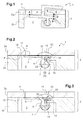
- the second wall 14 belongs in the example of Figures 2 and 3 to a portion 16 of the second portion 2b of the body 2 projecting into the duct 3.
- An intermediate piece 20 prevents direct contact between the flap 5 and the body 2 at the second zone 15. At least a portion of the intermediate piece 20 extends between the second wall 14 and the flap at the level of the second part. second zone 15 when the flap 5 is in the closed position, thus forming a stop for moving the flap 5 to the closed position.
- a housing 22 is formed in the projecting portion 16 and the intermediate piece 20 is partially received in this housing 22 and held in the latter, so that the portion 23 of the intermediate piece not received in the housing 22 is interposed between the body and the flap 5 at the second zone 15 when the flap 5 is in the closed position.
- the intermediate piece 20 is for example a pin, a screw or a rivet.
- the intermediate piece 20 When the intermediate piece 20 is a screw, it can be secured to the housing 22 by a deliberate deformation of the thread provided in the housing 22, as mentioned above, or with a counter nut cooperating with this screw 20.
- the housing 22 is formed in the flap 5 at the second zone 15 of the flap. Similar to what has been described with reference to the figure 2 , means for securing the intermediate piece 20 in the housing 22 may be provided so that the intermediate piece 20 is held in a position in which a portion 23 thereof extends out of the housing 22 to interpose between the second zone 15 and the second wall 14 of the second part 2b of the body 2.
- the flap 5 is made in one piece, in particular having a plate shape when it is observed in the plane of the figures, that is to say perpendicularly to the axis X of the shaft 7.
- Examples of Figures 4 and 5 differ from the examples of Figures 2 and 3 in particular by the fact that the first wall 12 and the second wall 14 both belong to the first part 2a of the body 2.
- the second wall 14 does not belong to the projecting portion 16, which is here formed in the first portion 2a and not in the second portion 2b of the body 2, but to a transition portion 26 interposed between said projecting portion 16 and the remainder of the first portion 2a of the body 2.
- This transition portion 26 extends in the plane of the figures between the end of the projecting portion 16 opposite its free end and the remainder of the first portion 2a.
- the portion 26 of the first portion 2a of the body 2 has a face facing the duct 3 and an opposite face opposite the second portion 2b of the body 2.
- part 5 presents two distinct parts 30 and 31.
- the first portion 30 is disposed at the first portion 2a of the body 2 when the flap is in the closed position and it extends on either side of the X axis of the shaft 7.
- the second zone 12 belongs in this example to the first part 30.
- the second part 31 carries the first contact zone 11 and extends here only on one side of the axis X of the shaft 7, to which it is connected by the support 9.
- the second part 31 is in the example of Figures 4 and 5 interposed between the support 9 and the first part 30.
- the housing 22 receiving a portion of the intermediate piece 20 is formed through the portion 26 and continues into the second portion 2b of the body 2.
- a portion 23 of said part is interposed between the second wall 14 and the second zone 12 of the flap.
- the housing 22 may be blind in the portion 26, that is to say, not extend to the second portion 2b of the body 2.
- figure 5 differs from that of the figure 4 by the fact that, similarly to what was described with reference to the figure 3 , the intermediate piece 20 is received in a housing 22 which is formed in the flap, and more precisely in the first part 30 of the flap 5.
- a first step 60 the flap 5 is brought into a position in which the second zone 15 is facing the second wall 14 of the second portion 2b of the body 2, while the first portion 2a of the body is removed and the intermediate part 20 is still movable relative to the flap 5 and the second part 2b.
- a step 61 once the preset value has been reached for this difference, the intermediate piece 20 is secured to the second part 2b of the body in the example of FIG. figure 2 , respectively to the second zone 15 of the flap 5 in the example of the figure 3 , so that when the flap 5 is in the closed position, the gap between the second zone 15 of the flap 5 and said second wall 14 of the second portion 2b of the body 2 has a value equal to the predefined value of the fact that a part 23 of the intermediate part 20 is interposed between the second zone 15 and the second wall 14.
- the first portion 2a of the body 2 is placed on the second portion 2b, and this first portion 2a of the body is then secured to the second portion 2b of the body.
- Steps 60 and 61 can be performed while a control piece of similar size to the first part 2a of the body, and having a wall against which the first zone 11 can come into contact when the flap 5 is in the closed position, is placed on the second part 2b of the flap 5.
- the presence of a cutout or other light in this adjustment piece by which access to the second area 15 of the flap is provided allows to adjust the gap related to the presence of the intermediate piece 20 and to secure it to the flap 5 or to the second part 2b of the body 2 although the adjustment piece is in place on the second part 2b of the body 2.
- the process can be carried out while the body of the valve is already assembled. In this case, it is not necessary to use an adjustment piece temporarily arranged in place of the first part 2a of the body 2.
- the adjustment of the deviation by action on the intermediate piece can be carried out of the body of the valve.
- the distance Dc defined as being the distance between the center of the housing 8 and the joint plane P of the body 2 may be less than the distance Dv, defined as being the distance between the center of the shaft 7 and the joint plane P 'of the flap 5.
- the joint plane of the flap P' is then located from the shaft 7 beyond the joint plane of the body P.
- the that the joint plane P 'of the flap 5 is located beyond the shaft 7 of the joint plane P of the body 2 does not prevent the flap 5 from reaching the closed position because of the existence of an additional game in the bearing or bearings.
- the shaft 7 moves radially relative to the direction X in the housing 8, so that the relative positions with respect to the shaft 7 of the joint plane P 'of the flap 5 and the joint plane P of the body 2 are modified.
- the distance Dc may be greater than the distance Dv, that is to say that the joint plane of the flap P 'is located below the shaft 7 of the joint plane of the body P.
- the distance Dc may be greater than the distance Dv, that is to say that the joint plane of the flap P 'is located below the shaft 7 of the joint plane of the body P.
- the first portion 30 of the flap 5 may or may not close a portion of the exhaust circuit of a heat engine while the duct 3 selectively closed by the second portion 31 of the flap is part of a recirculation loop to the admission of the engine.
Landscapes
- Engineering & Computer Science (AREA)
- General Engineering & Computer Science (AREA)
- Mechanical Engineering (AREA)
- Chemical & Material Sciences (AREA)
- Combustion & Propulsion (AREA)
- Lift Valve (AREA)
Claims (14)
- Ventil (1), insbesondere für eine Wärmekraftmaschine, umfassend:- einen Körper (2), in dem ausgenommen sind: eine Aufnahme (8), in der mindestens ein Lager und eine Leitung (3), die von einem Fluid durchströmt werden kann, angeordnet sind, und- eine Klappe (5), die schwenkbar in der Leitung (2) durch eine Welle (7), die mit einem Radialspiel in dem Lager aufgenommen ist, montiert ist,wobei die Klappe (5) schwenkt zwischen:- einer offenen Position und- einer geschlossenen Position, in der sie mit dem Körper (2) in Kontakt kommt:wobei der Übergang der Klappe (5) von der offenen Position in die geschlossene Position von einer Radialverschiebung der Welle (7) im Lager begleitet ist,- direkt durch eine erste Kontaktzone (11) der Klappe, die sich auf einer ersten Seite der Welle (7) befindet, und- indirekt über ein Zwischenstück (20), das nun zumindest teilweise zwischen dem Körper (2) und einer zweiten Zone (15) der Klappe (5) angeordnet ist, die sich auf einer zweiten Seite der Welle (7) gegenüber der ersten Seite befindet,
dadurch gekennzeichnet, dass das Ventil dazu vorgesehen ist, die Einstellung des Werts des Abstands, der durch die Anordnung des Zwischenstücks (20) zwischen der zweiten Zone (15) der Klappe und dem Körper (2) entsteht, zu ermöglichen. - Ventil nach Anspruch 1, wobei das Zwischenstück (20) derart ausgeführt ist, dass es mit dem Körper (2) verbunden werden kann, und die zweite Zone (15) der Klappe an dem Zwischenstück (20) zur Anlage gelangt, wenn sich die Klappe (5) in der geschlossenen Position befindet.
- Ventil nach Anspruch 1, wobei das Zwischenstück (20) derart ausgeführt ist, dass es mit der Klappe (5) verbunden werden kann, und das Zwischenstück (20) am Körper (2) zur Anlage gelangt, wenn sich die Klappe (5) in der geschlossenen Position befindet.
- Ventil nach einem der Ansprüche 1 bis 3, wobei der Körper (2) in einer Ebene senkrecht auf die Welle (7) einen Abschnitt (16) aufweist, der in der Leitung (3) herausragt, und wobei das Zwischenstück (20) zwischen dem herausragenden Abschnitt (16) und der zweiten Zone (15) der Klappe (5) angeordnet ist, wenn sich die Klappe (5) in der geschlossenen Position befindet.
- Ventil nach Anspruch 4, wobei der Körper (2) eine Aufnahme (22) umfasst, die in dem herausragenden Abschnitt (16) ausgenommen ist, und das Zwischenstück (20) und die Aufnahme (22) derart ausgeführt sind, dass das Zwischenstück (20) in der Aufnahme (22) aufgenommen, dann in dieser letztgenannten in mindestens einer vordefinierten Position gehalten werden kann.
- Ventil nach Anspruch 4, wobei die zweite Zone (15) der Klappe eine Aufnahme (22) umfasst, und das Zwischenstück (20) und die Aufnahme (22) derart ausgeführt sind, dass das Zwischenstück (20) in der Aufnahme (22) aufgenommen, dann in dieser letztgenannten in mindestens einer vordefinierten Position gehalten werden kann.
- Ventil nach einem der Ansprüche 1 bis 3, wobei der Körper (2) in einer Ebene senkrecht auf die Welle (7) einen in der Leitung (3) herausragenden Abschnitt (16) aufweist, wobei der Abschnitt (16) ein freies Ende und ein gegenüberliegendes Ende umfasst, das mit einem Übergangsabschnitt (26) verbunden ist, von dem nur eine Seite in der Ebene der Leitung (3) gegenüberliegt.
- Ventil nach Anspruch 7, wobei der Körper (2) eine Aufnahme (22) umfasst, die in dem Übergangsabschnitt (26) ausgenommen ist, und das Zwischenstück (20) und die Aufnahme (22) derart ausgeführt sind, dass das Zwischenstück (20) in der Aufnahme (22) aufgenommen, dann in dieser letztgenannten in mindestens einer vordefinierten Position gehalten werden kann.
- Ventil nach Anspruch 7, wobei die zweite Zone (15) der Klappe (5) eine Aufnahme (22) umfasst, und das Zwischenstück (20) und die Aufnahme (22) derart ausgeführt sind, dass das Zwischenstück (20) in der Aufnahme (22) aufgenommen, dann in dieser letztgenannten in mindestens einer vordefinierten Position gehalten werden kann.
- Ventil nach einem der Ansprüche 1 bis 9, wobei kein Dichtungselement zwischen der Klappe (5) und dem Körper (2) angeordnet ist, wenn sich die Klappe (5) in der geschlossenen Position befindet.
- Verfahren zur Steuerung der geschlossenen Position einer Klappe (5) eines Ventils (1), insbesondere eines Ventils für eine Wärmekraftmaschine, wobei das Ventil umfasst:- einen Körper (2), in dem eine Leitung (3) ausgenommen ist, und- eine Klappe (5), die schwenkbar in der Leitung (3) durch eine Welle (7) montiert ist, wobei die Klappe (5) zwischen einer offenen Position und einer geschlossenen Position schwenkt, wobei die Klappe (5) eine erste Zone (11), die geeignet ist, gegenüber einer ersten Wand (12) des Körpers (2) angeordnet zu werden, und eine zweite Zone (15) umfasst, die geeignet ist, gegenüber einer zweiten Wand (14) des Körpers (2) angeordnet zu werden, wenn sich die Klappe (5) in geschlossener Position befindet,wobei bei dem Verfahren:- die Klappe (5) in eine Position gebracht wird, in der die zweite Zone (15) der zweiten Wand (14) des Körpers (2) gegenüberliegt, und auf ein Zwischenstück (20), das sowohl in Bezug zum Körper (2) als auch zur Klappe (5) beweglich ist, eingewirkt wird, damit der Abstand zwischen der zweiten Zone (15) der Klappe (5) und der zweiten Wand (14) des Körpers (2) einen vordefinierten Wert annimmt,- wenn der vordefinierte Wert erreicht ist, das Zwischenstück (20) mit einem von Klappe (5) und Körper (2) verbunden wird, so dass, wenn sich die Klappe in der geschlossenen Position befindet, der Abstand zwischen der zweiten Zone (15) der Klappe und der zweiten Wand (14) des Körpers einen Wert gleich dem vordefinierten Wert hat, da das Zwischenstück (20) zumindest teilweise zwischen der zweiten Zone (15) der Klappe und der zweiten Wand (14) des Körpers angeordnet ist.
- Verfahren nach Anspruch 11, bei dem der Körper einen ersten (2a) und einen zweiten (2b) Teil umfasst, wobei die Leitung (3) nacheinander in dem ersten (2a) und in dem zweiten (2b) Teil des Körpers ausgenommen ist, und bei dem die erste Wand (12) dem ersten Teil (2a) des Körpers und die zweite Wand (14) dem zweiten Teil (2b) des Körpers angehört,
wobei bei dem Verfahren:- die Klappe in die Position gebracht wird, in der die zweite Zone (15) der zweiten Wand (14) des zweiten Teils (2b) des Körpers bei Nichtvorhandensein des ersten Teils (2a) des Körpers gegenüberliegt, und- der erste Teil (2a) des Körpers auf dem zweiten Teil (2b) des Körpers angeordnet wird, wenn das Zwischenstück (20) mit einem von Klappe (5) und Körper (2) verbunden ist. - Verfahren nach Anspruch 12, bei dem bei Nichtvorhandensein des ersten Teils (2a) des Körpers und vor der Verbindung des Zwischenstücks (20) ein Einstellteil auf dem zweiten Teil (2b) des Körpers angeordnet wird, wobei dieses Einstellteil Zugangsmittel zur zweiten Zone (15) der Klappe umfasst und mit dem Zwischenstück (20) zusammenwirkt, um es zu ermöglichen, auf das Zwischenstück (20) einzuwirken, um den Wert des Abstands zwischen der zweiten Zone (15) der Klappe (5) und der zweiten Wand (14) des Körpers (2) einzustellen.
- Verfahren nach Anspruch 13, bei dem der Körper (2) einen ersten (2a) und einen zweiten (2b) Teil umfasst, wobei die Leitung (3) nacheinander in dem ersten (2a) und in dem zweiten (2b) Teil des Körpers ausgenommen ist, und bei dem die erste Wand (12) und die zweite Wand (14) dem ersten Teil (2a) des Körpers angehören.
Applications Claiming Priority (2)
| Application Number | Priority Date | Filing Date | Title |
|---|---|---|---|
| FR1351661A FR3002608B1 (fr) | 2013-02-26 | 2013-02-26 | Vanne, notamment pour moteur thermique |
| PCT/FR2014/050346 WO2014131968A1 (fr) | 2013-02-26 | 2014-02-20 | Vanne, notamment pour moteur thermique |
Publications (2)
| Publication Number | Publication Date |
|---|---|
| EP2962019A1 EP2962019A1 (de) | 2016-01-06 |
| EP2962019B1 true EP2962019B1 (de) | 2016-10-19 |
Family
ID=48521225
Family Applications (1)
| Application Number | Title | Priority Date | Filing Date |
|---|---|---|---|
| EP14713160.1A Not-in-force EP2962019B1 (de) | 2013-02-26 | 2014-02-20 | Ventil, insbesondere für eine wärmekraftmaschine |
Country Status (3)
| Country | Link |
|---|---|
| EP (1) | EP2962019B1 (de) |
| FR (1) | FR3002608B1 (de) |
| WO (1) | WO2014131968A1 (de) |
Families Citing this family (1)
| Publication number | Priority date | Publication date | Assignee | Title |
|---|---|---|---|---|
| FR3046435B1 (fr) * | 2016-01-06 | 2019-05-10 | Valeo Systemes De Controle Moteur | Vanne de regulation de gaz d'echappement |
Family Cites Families (5)
| Publication number | Priority date | Publication date | Assignee | Title |
|---|---|---|---|---|
| GB745191A (en) * | 1952-12-08 | 1956-02-22 | Bronswerk Nv | Pivoted closing device |
| FR1259688A (fr) | 1960-06-08 | 1961-04-28 | Lightning Fasteners Ltd | Procédé et dispositif pour la fabrication de bandes dentelées |
| DE2427995A1 (de) * | 1974-06-10 | 1976-01-02 | Standard Elektrik Lorenz Ag | Klappenventil |
| DE10216537B3 (de) * | 2002-04-15 | 2004-02-05 | Visteon Global Technologies, Inc., Dearborn | Umsteuervorrichtung für strömende Medien, insbesondere Weichenventil für die Abgase einer Verbrennungskraftmaschine |
| FR2962184B1 (fr) * | 2010-06-30 | 2013-12-27 | Valeo Systemes De Controle Moteur | Vanne de circulation de fluide |
-
2013
- 2013-02-26 FR FR1351661A patent/FR3002608B1/fr not_active Expired - Fee Related
-
2014
- 2014-02-20 EP EP14713160.1A patent/EP2962019B1/de not_active Not-in-force
- 2014-02-20 WO PCT/FR2014/050346 patent/WO2014131968A1/fr not_active Ceased
Also Published As
| Publication number | Publication date |
|---|---|
| FR3002608A1 (fr) | 2014-08-29 |
| FR3002608B1 (fr) | 2015-03-13 |
| EP2962019A1 (de) | 2016-01-06 |
| WO2014131968A1 (fr) | 2014-09-04 |
Similar Documents
| Publication | Publication Date | Title |
|---|---|---|
| EP2850298B1 (de) | Ventil zum steuerung eines flüssigkeitsstroms mit einer drehverschlussvorrichtung | |
| FR3049673A1 (fr) | Vanne de ligne d'echappement et procede de montage correspondant | |
| FR3077864A1 (fr) | Soupape a boisseau sphérique avec un dispositif de garniture ajustable | |
| EP2588781B1 (de) | Flüssigkeitsventil | |
| EP2962019B1 (de) | Ventil, insbesondere für eine wärmekraftmaschine | |
| EP2881571B1 (de) | Vorrichtung zur Kontrolle eines einströmenden Gasflusses und/oder rückgeführten Abgasflusses in einem Zylinder eines Verbrennungsmotors, und entsprechendes Ansaugmodul | |
| EP2850297A1 (de) | Flüssigkeitsumlaufventil, insbesondere für ein kraftfahrzeug, und thermische aufbereitungsvorrichtung mit solch einem ventil | |
| EP3194817B1 (de) | Motorregelventil in einem kraftfahrzeug | |
| EP3025079B1 (de) | Ventil, insbesondere für verbrennungsmotor | |
| EP3194816B1 (de) | Motorregelventil in einem kraftfahrzeug | |
| EP3044487B1 (de) | Ventil, insbesondere für eine wärmekraftmaschine | |
| WO2014202883A1 (fr) | Vanne, notamment pour moteur thermique | |
| WO2009103867A2 (fr) | Conduit d'ecoulement de gaz pour vehicule automobile | |
| EP2850349B1 (de) | Flüssigkeitsumlaufventil | |
| EP3090168B1 (de) | Ventilelement, insbesondere für eine brennkraftmaschine | |
| FR3104665A1 (fr) | Vanne d’échappement automobile | |
| EP2917617B1 (de) | Ventil, insbesondere für einen verbrennungsmotor-luftschaltkreis | |
| WO2019048071A1 (fr) | Vanne anti cliquètement, ligne d'échappement comprenant une telle vanne et procédé de fabrication d'une telle vanne | |
| WO2010069781A1 (fr) | Canalisation d'ecoulement de fluide avec un volet d'obturation et procede de fabrication d'une telle canalisation | |
| WO2011121248A1 (fr) | Volet d'obturation d'un conduit d'ecoulement de gaz et conduit avec un tel volet |
Legal Events
| Date | Code | Title | Description |
|---|---|---|---|
| PUAI | Public reference made under article 153(3) epc to a published international application that has entered the european phase |
Free format text: ORIGINAL CODE: 0009012 |
|
| 17P | Request for examination filed |
Effective date: 20150803 |
|
| AK | Designated contracting states |
Kind code of ref document: A1 Designated state(s): AL AT BE BG CH CY CZ DE DK EE ES FI FR GB GR HR HU IE IS IT LI LT LU LV MC MK MT NL NO PL PT RO RS SE SI SK SM TR |
|
| AX | Request for extension of the european patent |
Extension state: BA ME |
|
| DAX | Request for extension of the european patent (deleted) | ||
| GRAP | Despatch of communication of intention to grant a patent |
Free format text: ORIGINAL CODE: EPIDOSNIGR1 |
|
| INTG | Intention to grant announced |
Effective date: 20160701 |
|
| GRAS | Grant fee paid |
Free format text: ORIGINAL CODE: EPIDOSNIGR3 |
|
| GRAA | (expected) grant |
Free format text: ORIGINAL CODE: 0009210 |
|
| AK | Designated contracting states |
Kind code of ref document: B1 Designated state(s): AL AT BE BG CH CY CZ DE DK EE ES FI FR GB GR HR HU IE IS IT LI LT LU LV MC MK MT NL NO PL PT RO RS SE SI SK SM TR |
|
| REG | Reference to a national code |
Ref country code: GB Ref legal event code: FG4D Free format text: NOT ENGLISH |
|
| REG | Reference to a national code |
Ref country code: CH Ref legal event code: EP |
|
| REG | Reference to a national code |
Ref country code: AT Ref legal event code: REF Ref document number: 838642 Country of ref document: AT Kind code of ref document: T Effective date: 20161115 |
|
| REG | Reference to a national code |
Ref country code: IE Ref legal event code: FG4D Free format text: LANGUAGE OF EP DOCUMENT: FRENCH |
|
| REG | Reference to a national code |
Ref country code: DE Ref legal event code: R096 Ref document number: 602014004373 Country of ref document: DE |
|
| REG | Reference to a national code |
Ref country code: NL Ref legal event code: MP Effective date: 20161019 |
|
| REG | Reference to a national code |
Ref country code: LT Ref legal event code: MG4D |
|
| PG25 | Lapsed in a contracting state [announced via postgrant information from national office to epo] |
Ref country code: LV Free format text: LAPSE BECAUSE OF FAILURE TO SUBMIT A TRANSLATION OF THE DESCRIPTION OR TO PAY THE FEE WITHIN THE PRESCRIBED TIME-LIMIT Effective date: 20161019 |
|
| REG | Reference to a national code |
Ref country code: FR Ref legal event code: PLFP Year of fee payment: 4 |
|
| REG | Reference to a national code |
Ref country code: AT Ref legal event code: MK05 Ref document number: 838642 Country of ref document: AT Kind code of ref document: T Effective date: 20161019 |
|
| PG25 | Lapsed in a contracting state [announced via postgrant information from national office to epo] |
Ref country code: NO Free format text: LAPSE BECAUSE OF FAILURE TO SUBMIT A TRANSLATION OF THE DESCRIPTION OR TO PAY THE FEE WITHIN THE PRESCRIBED TIME-LIMIT Effective date: 20170119 Ref country code: SE Free format text: LAPSE BECAUSE OF FAILURE TO SUBMIT A TRANSLATION OF THE DESCRIPTION OR TO PAY THE FEE WITHIN THE PRESCRIBED TIME-LIMIT Effective date: 20161019 Ref country code: LT Free format text: LAPSE BECAUSE OF FAILURE TO SUBMIT A TRANSLATION OF THE DESCRIPTION OR TO PAY THE FEE WITHIN THE PRESCRIBED TIME-LIMIT Effective date: 20161019 Ref country code: GR Free format text: LAPSE BECAUSE OF FAILURE TO SUBMIT A TRANSLATION OF THE DESCRIPTION OR TO PAY THE FEE WITHIN THE PRESCRIBED TIME-LIMIT Effective date: 20170120 |
|
| PG25 | Lapsed in a contracting state [announced via postgrant information from national office to epo] |
Ref country code: AT Free format text: LAPSE BECAUSE OF FAILURE TO SUBMIT A TRANSLATION OF THE DESCRIPTION OR TO PAY THE FEE WITHIN THE PRESCRIBED TIME-LIMIT Effective date: 20161019 Ref country code: HR Free format text: LAPSE BECAUSE OF FAILURE TO SUBMIT A TRANSLATION OF THE DESCRIPTION OR TO PAY THE FEE WITHIN THE PRESCRIBED TIME-LIMIT Effective date: 20161019 Ref country code: BE Free format text: LAPSE BECAUSE OF NON-PAYMENT OF DUE FEES Effective date: 20170228 Ref country code: NL Free format text: LAPSE BECAUSE OF FAILURE TO SUBMIT A TRANSLATION OF THE DESCRIPTION OR TO PAY THE FEE WITHIN THE PRESCRIBED TIME-LIMIT Effective date: 20161019 Ref country code: FI Free format text: LAPSE BECAUSE OF FAILURE TO SUBMIT A TRANSLATION OF THE DESCRIPTION OR TO PAY THE FEE WITHIN THE PRESCRIBED TIME-LIMIT Effective date: 20161019 Ref country code: PL Free format text: LAPSE BECAUSE OF FAILURE TO SUBMIT A TRANSLATION OF THE DESCRIPTION OR TO PAY THE FEE WITHIN THE PRESCRIBED TIME-LIMIT Effective date: 20161019 Ref country code: IS Free format text: LAPSE BECAUSE OF FAILURE TO SUBMIT A TRANSLATION OF THE DESCRIPTION OR TO PAY THE FEE WITHIN THE PRESCRIBED TIME-LIMIT Effective date: 20170219 Ref country code: RS Free format text: LAPSE BECAUSE OF FAILURE TO SUBMIT A TRANSLATION OF THE DESCRIPTION OR TO PAY THE FEE WITHIN THE PRESCRIBED TIME-LIMIT Effective date: 20161019 Ref country code: ES Free format text: LAPSE BECAUSE OF FAILURE TO SUBMIT A TRANSLATION OF THE DESCRIPTION OR TO PAY THE FEE WITHIN THE PRESCRIBED TIME-LIMIT Effective date: 20161019 Ref country code: PT Free format text: LAPSE BECAUSE OF FAILURE TO SUBMIT A TRANSLATION OF THE DESCRIPTION OR TO PAY THE FEE WITHIN THE PRESCRIBED TIME-LIMIT Effective date: 20170220 |
|
| REG | Reference to a national code |
Ref country code: DE Ref legal event code: R097 Ref document number: 602014004373 Country of ref document: DE |
|
| PG25 | Lapsed in a contracting state [announced via postgrant information from national office to epo] |
Ref country code: EE Free format text: LAPSE BECAUSE OF FAILURE TO SUBMIT A TRANSLATION OF THE DESCRIPTION OR TO PAY THE FEE WITHIN THE PRESCRIBED TIME-LIMIT Effective date: 20161019 Ref country code: DK Free format text: LAPSE BECAUSE OF FAILURE TO SUBMIT A TRANSLATION OF THE DESCRIPTION OR TO PAY THE FEE WITHIN THE PRESCRIBED TIME-LIMIT Effective date: 20161019 Ref country code: RO Free format text: LAPSE BECAUSE OF FAILURE TO SUBMIT A TRANSLATION OF THE DESCRIPTION OR TO PAY THE FEE WITHIN THE PRESCRIBED TIME-LIMIT Effective date: 20161019 Ref country code: SK Free format text: LAPSE BECAUSE OF FAILURE TO SUBMIT A TRANSLATION OF THE DESCRIPTION OR TO PAY THE FEE WITHIN THE PRESCRIBED TIME-LIMIT Effective date: 20161019 Ref country code: CZ Free format text: LAPSE BECAUSE OF FAILURE TO SUBMIT A TRANSLATION OF THE DESCRIPTION OR TO PAY THE FEE WITHIN THE PRESCRIBED TIME-LIMIT Effective date: 20161019 |
|
| PLBE | No opposition filed within time limit |
Free format text: ORIGINAL CODE: 0009261 |
|
| STAA | Information on the status of an ep patent application or granted ep patent |
Free format text: STATUS: NO OPPOSITION FILED WITHIN TIME LIMIT |
|
| PG25 | Lapsed in a contracting state [announced via postgrant information from national office to epo] |
Ref country code: IT Free format text: LAPSE BECAUSE OF FAILURE TO SUBMIT A TRANSLATION OF THE DESCRIPTION OR TO PAY THE FEE WITHIN THE PRESCRIBED TIME-LIMIT Effective date: 20161019 Ref country code: SM Free format text: LAPSE BECAUSE OF FAILURE TO SUBMIT A TRANSLATION OF THE DESCRIPTION OR TO PAY THE FEE WITHIN THE PRESCRIBED TIME-LIMIT Effective date: 20161019 Ref country code: BG Free format text: LAPSE BECAUSE OF FAILURE TO SUBMIT A TRANSLATION OF THE DESCRIPTION OR TO PAY THE FEE WITHIN THE PRESCRIBED TIME-LIMIT Effective date: 20170119 |
|
| 26N | No opposition filed |
Effective date: 20170720 |
|
| PG25 | Lapsed in a contracting state [announced via postgrant information from national office to epo] |
Ref country code: MC Free format text: LAPSE BECAUSE OF FAILURE TO SUBMIT A TRANSLATION OF THE DESCRIPTION OR TO PAY THE FEE WITHIN THE PRESCRIBED TIME-LIMIT Effective date: 20161019 |
|
| REG | Reference to a national code |
Ref country code: CH Ref legal event code: PL |
|
| PG25 | Lapsed in a contracting state [announced via postgrant information from national office to epo] |
Ref country code: LI Free format text: LAPSE BECAUSE OF NON-PAYMENT OF DUE FEES Effective date: 20170228 Ref country code: CH Free format text: LAPSE BECAUSE OF NON-PAYMENT OF DUE FEES Effective date: 20170228 |
|
| REG | Reference to a national code |
Ref country code: IE Ref legal event code: MM4A |
|
| PG25 | Lapsed in a contracting state [announced via postgrant information from national office to epo] |
Ref country code: SI Free format text: LAPSE BECAUSE OF FAILURE TO SUBMIT A TRANSLATION OF THE DESCRIPTION OR TO PAY THE FEE WITHIN THE PRESCRIBED TIME-LIMIT Effective date: 20161019 |
|
| PG25 | Lapsed in a contracting state [announced via postgrant information from national office to epo] |
Ref country code: LU Free format text: LAPSE BECAUSE OF NON-PAYMENT OF DUE FEES Effective date: 20170220 |
|
| REG | Reference to a national code |
Ref country code: BE Ref legal event code: MM Effective date: 20170228 |
|
| REG | Reference to a national code |
Ref country code: FR Ref legal event code: PLFP Year of fee payment: 5 |
|
| PG25 | Lapsed in a contracting state [announced via postgrant information from national office to epo] |
Ref country code: IE Free format text: LAPSE BECAUSE OF NON-PAYMENT OF DUE FEES Effective date: 20170220 |
|
| PG25 | Lapsed in a contracting state [announced via postgrant information from national office to epo] |
Ref country code: MT Free format text: LAPSE BECAUSE OF FAILURE TO SUBMIT A TRANSLATION OF THE DESCRIPTION OR TO PAY THE FEE WITHIN THE PRESCRIBED TIME-LIMIT Effective date: 20161019 |
|
| GBPC | Gb: european patent ceased through non-payment of renewal fee |
Effective date: 20180220 |
|
| PG25 | Lapsed in a contracting state [announced via postgrant information from national office to epo] |
Ref country code: GB Free format text: LAPSE BECAUSE OF NON-PAYMENT OF DUE FEES Effective date: 20180220 |
|
| PG25 | Lapsed in a contracting state [announced via postgrant information from national office to epo] |
Ref country code: HU Free format text: LAPSE BECAUSE OF FAILURE TO SUBMIT A TRANSLATION OF THE DESCRIPTION OR TO PAY THE FEE WITHIN THE PRESCRIBED TIME-LIMIT; INVALID AB INITIO Effective date: 20140220 |
|
| PG25 | Lapsed in a contracting state [announced via postgrant information from national office to epo] |
Ref country code: CY Free format text: LAPSE BECAUSE OF FAILURE TO SUBMIT A TRANSLATION OF THE DESCRIPTION OR TO PAY THE FEE WITHIN THE PRESCRIBED TIME-LIMIT Effective date: 20161019 |
|
| PG25 | Lapsed in a contracting state [announced via postgrant information from national office to epo] |
Ref country code: MK Free format text: LAPSE BECAUSE OF FAILURE TO SUBMIT A TRANSLATION OF THE DESCRIPTION OR TO PAY THE FEE WITHIN THE PRESCRIBED TIME-LIMIT Effective date: 20161019 |
|
| PG25 | Lapsed in a contracting state [announced via postgrant information from national office to epo] |
Ref country code: TR Free format text: LAPSE BECAUSE OF FAILURE TO SUBMIT A TRANSLATION OF THE DESCRIPTION OR TO PAY THE FEE WITHIN THE PRESCRIBED TIME-LIMIT Effective date: 20161019 |
|
| PG25 | Lapsed in a contracting state [announced via postgrant information from national office to epo] |
Ref country code: AL Free format text: LAPSE BECAUSE OF FAILURE TO SUBMIT A TRANSLATION OF THE DESCRIPTION OR TO PAY THE FEE WITHIN THE PRESCRIBED TIME-LIMIT Effective date: 20161019 |
|
| PGFP | Annual fee paid to national office [announced via postgrant information from national office to epo] |
Ref country code: FR Payment date: 20230227 Year of fee payment: 10 |
|
| PGFP | Annual fee paid to national office [announced via postgrant information from national office to epo] |
Ref country code: DE Payment date: 20230207 Year of fee payment: 10 |
|
| P01 | Opt-out of the competence of the unified patent court (upc) registered |
Effective date: 20230528 |
|
| REG | Reference to a national code |
Ref country code: DE Ref legal event code: R119 Ref document number: 602014004373 Country of ref document: DE |
|
| PG25 | Lapsed in a contracting state [announced via postgrant information from national office to epo] |
Ref country code: DE Free format text: LAPSE BECAUSE OF NON-PAYMENT OF DUE FEES Effective date: 20240903 |
|
| PG25 | Lapsed in a contracting state [announced via postgrant information from national office to epo] |
Ref country code: FR Free format text: LAPSE BECAUSE OF NON-PAYMENT OF DUE FEES Effective date: 20240229 |
|
| PG25 | Lapsed in a contracting state [announced via postgrant information from national office to epo] |
Ref country code: FR Free format text: LAPSE BECAUSE OF NON-PAYMENT OF DUE FEES Effective date: 20240229 Ref country code: DE Free format text: LAPSE BECAUSE OF NON-PAYMENT OF DUE FEES Effective date: 20240903 |