EP2961968B1 - Gasturbinenmotor - Google Patents
Gasturbinenmotor Download PDFInfo
- Publication number
- EP2961968B1 EP2961968B1 EP14756398.5A EP14756398A EP2961968B1 EP 2961968 B1 EP2961968 B1 EP 2961968B1 EP 14756398 A EP14756398 A EP 14756398A EP 2961968 B1 EP2961968 B1 EP 2961968B1
- Authority
- EP
- European Patent Office
- Prior art keywords
- clutch
- shaft
- cage
- gas turbine
- compressor
- Prior art date
- Legal status (The legal status is an assumption and is not a legal conclusion. Google has not performed a legal analysis and makes no representation as to the accuracy of the status listed.)
- Active
Links
Images




Classifications
-
- F—MECHANICAL ENGINEERING; LIGHTING; HEATING; WEAPONS; BLASTING
- F02—COMBUSTION ENGINES; HOT-GAS OR COMBUSTION-PRODUCT ENGINE PLANTS
- F02C—GAS-TURBINE PLANTS; AIR INTAKES FOR JET-PROPULSION PLANTS; CONTROLLING FUEL SUPPLY IN AIR-BREATHING JET-PROPULSION PLANTS
- F02C7/00—Features, components parts, details or accessories, not provided for in, or of interest apart form groups F02C1/00 - F02C6/00; Air intakes for jet-propulsion plants
- F02C7/26—Starting; Ignition
- F02C7/268—Starting drives for the rotor, acting directly on the rotor of the gas turbine to be started
- F02C7/275—Mechanical drives
-
- F—MECHANICAL ENGINEERING; LIGHTING; HEATING; WEAPONS; BLASTING
- F01—MACHINES OR ENGINES IN GENERAL; ENGINE PLANTS IN GENERAL; STEAM ENGINES
- F01D—NON-POSITIVE DISPLACEMENT MACHINES OR ENGINES, e.g. STEAM TURBINES
- F01D19/00—Starting of machines or engines; Regulating, controlling, or safety means in connection therewith
-
- F—MECHANICAL ENGINEERING; LIGHTING; HEATING; WEAPONS; BLASTING
- F02—COMBUSTION ENGINES; HOT-GAS OR COMBUSTION-PRODUCT ENGINE PLANTS
- F02C—GAS-TURBINE PLANTS; AIR INTAKES FOR JET-PROPULSION PLANTS; CONTROLLING FUEL SUPPLY IN AIR-BREATHING JET-PROPULSION PLANTS
- F02C3/00—Gas-turbine plants characterised by the use of combustion products as the working fluid
- F02C3/04—Gas-turbine plants characterised by the use of combustion products as the working fluid having a turbine driving a compressor
- F02C3/107—Gas-turbine plants characterised by the use of combustion products as the working fluid having a turbine driving a compressor with two or more rotors connected by power transmission
-
- F—MECHANICAL ENGINEERING; LIGHTING; HEATING; WEAPONS; BLASTING
- F02—COMBUSTION ENGINES; HOT-GAS OR COMBUSTION-PRODUCT ENGINE PLANTS
- F02C—GAS-TURBINE PLANTS; AIR INTAKES FOR JET-PROPULSION PLANTS; CONTROLLING FUEL SUPPLY IN AIR-BREATHING JET-PROPULSION PLANTS
- F02C7/00—Features, components parts, details or accessories, not provided for in, or of interest apart form groups F02C1/00 - F02C6/00; Air intakes for jet-propulsion plants
- F02C7/36—Power transmission arrangements between the different shafts of the gas turbine plant, or between the gas-turbine plant and the power user
-
- F—MECHANICAL ENGINEERING; LIGHTING; HEATING; WEAPONS; BLASTING
- F05—INDEXING SCHEMES RELATING TO ENGINES OR PUMPS IN VARIOUS SUBCLASSES OF CLASSES F01-F04
- F05D—INDEXING SCHEME FOR ASPECTS RELATING TO NON-POSITIVE-DISPLACEMENT MACHINES OR ENGINES, GAS-TURBINES OR JET-PROPULSION PLANTS
- F05D2260/00—Function
- F05D2260/40—Transmission of power
-
- F—MECHANICAL ENGINEERING; LIGHTING; HEATING; WEAPONS; BLASTING
- F05—INDEXING SCHEMES RELATING TO ENGINES OR PUMPS IN VARIOUS SUBCLASSES OF CLASSES F01-F04
- F05D—INDEXING SCHEME FOR ASPECTS RELATING TO NON-POSITIVE-DISPLACEMENT MACHINES OR ENGINES, GAS-TURBINES OR JET-PROPULSION PLANTS
- F05D2260/00—Function
- F05D2260/40—Transmission of power
- F05D2260/403—Transmission of power through the shape of the drive components
-
- F—MECHANICAL ENGINEERING; LIGHTING; HEATING; WEAPONS; BLASTING
- F05—INDEXING SCHEMES RELATING TO ENGINES OR PUMPS IN VARIOUS SUBCLASSES OF CLASSES F01-F04
- F05D—INDEXING SCHEME FOR ASPECTS RELATING TO NON-POSITIVE-DISPLACEMENT MACHINES OR ENGINES, GAS-TURBINES OR JET-PROPULSION PLANTS
- F05D2260/00—Function
- F05D2260/85—Starting
Definitions
- the present disclosure relates generally to gas turbine engine architectures. More particularly, the present disclosure relates to systems for starting gas turbine engines.
- Conventional dual spool gas turbine engines comprise a high pressure compressor and a high pressure turbine that define a core spool.
- the core spool generates a gas flow that drives a low pressure spool.
- the low pressure spool comprises a propulsor turbine, which powers a low pressure compressor and a fan.
- operation of the engine is initiated by a starter that is coupled to the core spool through a tower shaft.
- the starter provides rotation to the core spool while fuel is injected into a combustor and ignited to initiate a combustion process that subsequently sustains rotation of the core spool and simultaneously the low pressure spool. Once the engine is rotating via the combustion process, the starter acts as a generator.
- the tower shaft requires coupling to a core spool shaft and the starter through elaborate gear systems. Furthermore, the tower shaft requires access to an axial length of the core spool shaft, which necessitates elongation of the core spool. There is, therefore, a need for a simpler starter-generator system that utilizes less space in the gas turbine engine.
- US 2007/0277532 relates to two-shaft engines for aircraft with high electric power demand.
- US 2011/0094236 relates to compressed air storage systems.
- WO 2011/162845 relates to an adaptive fan for a variable cycle gas turbine engine.
- US 4,531,620 relates to ramp/roller freewheel clutches.
- US 3,187,869 relates to a one-way clutch.
- EP 1980732A2 relates to a clutch actuated by a solenoid/overrunning clutch.
- US5086657A relates to a clutch actuated by pinned flyweights.
- the present disclosure is directed to a gas turbine engine comprising a low pressure compressor, a high pressure compressor, a starter generator and a clutch.
- the starter generator is coupled to the low pressure compressor.
- the clutch selectively couples the high pressure compressor and the low pressure compressor.
- the present disclosure is directed to a method for starting a gas turbine engine.
- the method comprises engaging a low pressure compressor with a high pressure compressor utilizing a clutch, rotating the low pressure compressor and the high pressure compressor utilizing a starter generator coupled to the low pressure compressor, igniting the gas turbine engine, and disengaging the clutch at an operational speed of the gas turbine engine.
- the present disclosure is directed to a clutch mechanism, such as for use with a gas turbine engine compressor system.
- the clutch mechanism is disposed between a first compressor shaft and a second compressor shaft to engage the first compressor shaft with the second compressor shaft at rest.
- a flyweight system is engaged with the clutch - 50D, or through a shaft extension so as to be axially forward of rotors 50A - 50D, such as shown in FIG. 1 .
- Rotors 50A - 50D are coupled to each other at their outer diameter rims so as to rotate in unison. Rotors 50A - 50D include hub portions at their inner diameters to provide balance.
- the hub of rotor 50C includes radial extension 76A and axial extension 76B, which couple to low pressure shaft 22, such as through a spline or some other conventional coupling.
- First bearing 72 is disposed atop, or radially outward of, axial extension 76B.
- Forward strut 68 extends from transition duct 66, which is stationarily mounted within gas turbine engine 10, to low pressure shaft 22 to support second spool 29B.
- Low pressure shaft 22 extends axially rearward from axial extension 76B, concentrically inside of first spool 29A, to low pressure turbine 20 ( FIG. 1 ).
- Rotors 58A - 58E are coupled to each other at their outer diameter rims so as to rotate in unison. Rotors 58A - 58E include hub portions at their inner diameters to provide balance.
- the hub of rotor 58C includes axial extension 78A, which supports second bearing 74, and stub shaft 78B, which connects to clutch 16.
- Rotor 58E is connected to high pressure shaft 26, which extends through combustor section 28 to join to high pressure turbine 24 ( FIG. 1 ).
- Second bearing 74 is disposed atop, or radially outward of, axial extension 78A.
- Aft strut 70 extends from transition duct 66, which is stationarily mounted within gas turbine engine 10, to axial extension 78A to support first spool 29A.
- Clutch 16 connects stub shaft 78B of first spool 29A to low pressure shaft 22 of second spool 29B via clutch shaft 80.
- clutch 16 is mounted to low pressure shaft 22 so as to be continuously engaged with second spool 29B and continuously rotating with low pressure shaft 22.
- Clutch 16 is configured to engage with stub shaft 78B of first spool 29A at rest and up to a threshold rotational speed.
- the threshold rotational speed is a speed at which both first spool 29A and second spool 29B are rotating and at which gas turbine engine 10 is able to sustain operation based on the combustion process being carried out in combustor section 28 ( FIG. 1 ).
- clutch 16 is configured to disengage with stub shaft 78B to allow freewheeling of first spool 29A relative to second spool 29B.
- first spool 29A tends to rotate faster than second spool 29B.
- the illustrated turboprop has an aft mounted propulsor.
- FIG. 1 and the corresponding description thereof provide an overview of the various systems and operations of a gas turbine engine. The present application is additionally applicable to all types of gas turbine engines, including industrial gas turbines, turboshaft engines, turbofan engines, turboprop engines having a forward mounted propulsor, and the like.
- Incoming ambient air 42 enters gas turbine engine 10 at low pressure compressor 14 and subsequently passes through high pressure compressor 18 to become pressurized air 44.
- Fuel mixes with pressurized air 44 in combustor section 28, where it is burned after being lighted with an igniter, as is known in the art.
- Combustion gases 46 expand through high pressure turbine 24 and low pressure turbine 20.
- Combustion gases 46 continue through gas turbine engine 10 to enter propulsor module 30.
- Combustion gases 46 rotate power turbine 32, which rotates power shaft 34A.
- Power shaft 34A drives gear system 36, which rotates power shaft 34B.
- Gear system 36 reduces the speed of power shaft 34B relative to power shaft 34A.
- gear system 36 comprises an epicyclic gear system, such as a planetary gear system or a star gear system.
- Power shaft 34B provides input to propeller system 38.
- propeller system 38 includes first stage propellers 48A and second stage propellers 48B.
- First stage propellers 48A and second stage propellers 48B generate thrust, which is used to push an aircraft to which gas turbine engine 10 is mounted.
- Starter generator 12 is coupled to low pressure compressor 14, which is linked to high pressure compressor 18 via clutch 16. Starter generator 12 is coupled to a forward end of low pressure compressor 14 coaxially along engine centerline 40. Mounting of starter generator 12 in such a location provides direct axis to low pressure shaft 22, which eliminates the need for angled or beveled gear systems and tower shafts. Furthermore, the location of starter generator does not require access to an axial length of low pressure shaft 22, which enables the axial size of engine 10, gas generator module 29 in particular, to be shortened.
- Starter generator 12 comprises an electric motor, as is known in the art, that can be mechanically driven to generate electrical power. Starter generator 12 is connected to a source of electrical power (not shown) to provide mechanical input to gas generator module 29.
- a starter shaft (not shown) is rotated that provides rotational input to low pressure compressor 14, which rotates low pressure shaft 22.
- Low pressure compressor 14 is mechanically coupled to high pressure compressor 18 through clutch 16 such that rotation of low pressure compressor 14 also rotates high pressure compressor 18.
- Clutch 16 is configured to be engaged at rest and up to a threshold rotational speed.
- first spool 29A and second spool 29B can rotate independently of each other.
- first spool 29A rotates at higher speeds than the low pressure, second spool 29B.
- clutch 16 disengages under centrifugal force generated by rotation of low pressure shaft 22.
- FIG. 2 is a schematic cross-sectional view of low pressure compressor 14 coupled to high pressure compressor 18 via clutch 16.
- Low pressure compressor 14 comprises a plurality of interconnected rotors 50A - 50D, each comprising a plurality of blades 52A - 52D.
- a plurality of vanes 54A - 54D extend radially inward from low pressure compressor case 56 to be interposed with blades 52A - 52D.
- high pressure compressor 18 includes rotors 58A - 58E, blades 60A - 60E, vanes 62A - 62D and case 64.
- Transition duct 66 fluidly connects the exit of low pressure compressor 14 with the inlet of high pressure compressor 18.
- Second spool 29B further includes bearing 72, radial extension 76A and axial extension 76B.
- First spool 29A further includes bearing 74, axial extension 78A and stub shaft 78B.
- Forward strut 68 extends from transition duct 66 to low pressure shaft 22, and aft strut 70 extends from transition duct 66 to axial extension 78A.
- First bearing 72 is disposed between forward strut 68 and low pressure shaft 22, and second bearing 74 is disposed between aft strut 70 and axial extension 78A.
- the forward end of low pressure shaft 22 is easily accessible within low pressure compressor 14 close to engine centerline 40 ( FIG. 1 ).
- low pressure shaft 22 includes flange 79, which may be used to couple to starter generator 12 either directly so as to be radially within rotors 50A - 50D, or through a shaft extension so as to be axially forward of rotors 50A - 50D, such as shown in FIG. 1 .
- Rotors 50A - 50D are coupled to each other at their outer diameter rims so as to rotate in unison. Rotors 50A - 50D include hub portions at their inner diameters to provide balance.
- the hub of rotor 50C includes radial extension 76A and axial extension 76B, which couple to low pressure shaft 22, such as through a spline or some other conventional coupling.
- First bearing 72 is disposed atop, or radially outward of, axial extension 76B.
- Forward strut 68 extends from transition duct 66, which is stationarily mounted within gas turbine engine 10, to low pressure shaft 22 to support second spool 29B.
- Low pressure shaft 22 extends axially rearward from axial extension 76B, concentrically inside of first spool 29A, to low pressure turbine 20 ( FIG. 1 ).
- Rotors 58A - 58E are coupled to each other at their outer diameter rims so as to rotate in unison. Rotors 58A - 58E include hub portions at their inner diameters to provide balance.
- the hub of rotor 58C includes axial extension 78A, which supports second bearing 74, and stub shaft 78B, which connects to clutch 16.
- Rotor 58E is connected to high pressure shaft 26, which extends through combustor section 28 to join to high pressure turbine 24 ( FIG. 1 ).
- Second bearing 74 is disposed atop, or radially outward of, axial extension 78A.
- Aft strut 70 extends from transition duct 66, which is stationarily mounted within gas turbine engine 10, to axial extension 78A to support first spool 29A.
- Clutch 16 connects stub shaft 78B of first spool 29A to low pressure shaft 22 of second spool 29B via clutch shaft 80.
- clutch 16 is mounted to low pressure shaft 22 so as to be continuously engaged with second spool 29B and continuously rotating with low pressure shaft 22.
- Clutch 16 is configured to engage with stub shaft 78 of first spool 29A at rest and up to a threshold rotational speed.
- the threshold rotational speed is a speed at which both first spool 29A and second spool 29B are rotating and at which gas turbine engine 10 is able to sustain operation based on the combustion process being carried out in combustor section 28 ( FIG. 1 ).
- clutch 16 is configured to disengage with stub shaft 78B to allow freewheeling of first spool 29A relative to second spool 29B. As mentioned, once engine 10 has reached idle speed, first spool 29A tends to rotate faster than second spool 29B.
- clutch 16 comprises a ramp/roller (double cage) clutch.
- clutch 16 may comprise an actively controlled ramp/roller clutch as is described in U.S. Pat. No. 4,531,620 , which is assigned to United Technologies Corporation and is incorporated herein by reference.
- clutch 16 is an automatically actuated ramp/roller clutch that releases at the threshold rotational speed.
- clutch 16 may comprise any other suitable clutch, such as a Sprag clutch.
- clutch 16 is configured as a ramp/roller clutch that releases based on actuation of a flyweight under centrifugal loading, as is described with reference to FIGS. 3 - 6 .
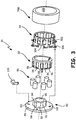
- FIG. 3 is an exploded view of clutch 16 comprising a ramp/roller clutch mechanism suitable for coupling compressors 14 and 16 of FIGS. 1 and 2 .
- Clutch 16 includes actuation cage 82, stationary cage 84 and rollers 86, in addition to being linked to stub shaft 78B and clutch shaft 80.
- Clutch shaft 80 includes flange 88, bore 90, indentations 92 and ramps 94.
- Actuation cage 82 includes bars 96, windows 98 and lug 100.
- Stationary cage 84 includes slots 102, ramps 104 and mounting flanges 106.
- Stub shaft 78B includes inner surface 108.
- Clutch 16 also includes actuator arm 109.
- Clutch shaft 80 is coupled to low pressure shaft 22, such as by a spline at bore 90.
- the outer diameter surface of clutch shaft 80 is configured as a sprocket-like body defined by indentations 92 and ramps 94.
- Each indentation 92 corresponds to one of rollers 86, each of which comprises a cylindrical body, but that may have other configurations.
- Rollers 86 are spaced peripherally about clutch shaft 80 by insertion into windows 98 of actuation cage 82.
- Actuation cage 82 is rotated within clutch 16, such as with lug 100, to move rollers 86 from indentations 92 to ramps 94, and vice versa, via interaction with bars 96.
- lug 100 is biased by a pin to move rollers 86 over ramps 94 to normally cause clutch 16 to be in an engaged state, as illustrated in FIG. 4A .
- actuation cage 82 is pushed by actuator arm 109 to push rollers 86 under ramps 104.
- Positioning of rollers 86 under ramps 104 causes clutch 16 to be in a freewheeling state, as illustrated in FIG. 4B .
- Stationary cage 84 is positioned concentrically around actuation cage 82 and clutch shaft 80, and coupled to flange 88 of clutch shaft 80 via fasteners (not shown) inserted through mounting flanges 106 and into bores 110.
- Stationary cage 84 is thus stationary with reference to clutch shaft 80 and low pressure shaft 22 ( FIG. 3 ), but rotates within engine 10 about engine centerline 40 ( FIG. 1 ).
- rollers 86 are either disposed within slots 102 ( FIG. 4A ) in an engaged mode, or radially inward of ramps 104 ( FIG. 4B ) in a freewheeling mode.
- Stub shaft 78B is fitted over stationary cage 84 so that inner surface 108 surrounds ramps 104.
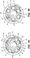
- FIG. 4A is a cross-sectional view of an assembly of clutch 16 of FIG. 3 wherein rollers 86 are radially locked between stub shaft 78B and ramps 94 of clutch shaft 80 via positioning of actuation cage 82.
- clutch shaft 80 being driven counterclockwise as illustrated in FIG. 4A , each roller 86 is wedged between a corresponding ramp 94 and bore 108 of stub shaft 78B.
- stub shaft 78B rotates counterclockwise with clutch shaft 80.
- actuation cage 82 is pushed clockwise into the position shown in FIG. 4A via a spring-actuated pin.
- Ramps 94 have surfaces that are angled with respect to a line tangent to clutch shaft 80 at each ramp to facilitate clutch shaft 80 rotating counterclockwise underneath rollers 86. Ramps 94 are additionally angled to prevent clutch shaft 80 from driving stub shaft 78B in the clockwise direction. The distance between a circumferential segment of ramps 94 and inner surface 108 less than the diameter of rollers 86. Thus, as bars 96 of actuation cage 82 push rollers 86 up ramps 94, rollers 86 are put into compression between surface 108 and ramps 94 to interlock stub shaft 78B and clutch shaft 80, which then rotate together as a unit.
- clutch shaft 80 when starter generator 12 ( FIG. 2 ) is actuated as a motor, clutch shaft 80 is rotated. Rotation of clutch shaft 80 simultaneously causes stub shaft 78B to rotate. Clutch shaft 80 and stub shaft 78B continue to rotate together until a threshold rotational speed is reached.
- FIG. 4B is a cross-sectional view of an assembly of clutch 16 of FIG. 3 wherein rollers 86 are radially contained between stationary cage 84 and indentations 92 of clutch shaft 80 via displacement of actuation cage 82. If stub shaft 78B begins to rotate counterclockwise faster than clutch shaft 80, rollers 86 will begin to roll down ramps 94 into indentations 92.
- actuation cage 82 is rotated counterclockwise with respect to clutch shaft 80 so that the rollers 86 are advanced into corresponding indentations 92. Rollers 86 are simultaneously rolled onto ramps 104 of stationary cage 84. The distance between indentations 92 and ramps 104 is greater than the diameter of rollers 86.
- Stationary cage 84 is mounted directly to clutch shaft 80 via mounting flanges 106 ( FIG. 3 ) and flange 88. Mounting of cage 84 directly on clutch shaft 80 enables stationary cage 84 to retain its original position with respect to clutch shaft 80.
- actuation cage 82 is moved relatively counterclockwise with respect to clutch shaft 80 by actuation arm 109 ( FIG. 3 )
- mounting of cage 84 directly on clutch shaft 80 causes rollers 86 to become lodged between indentations 92 and ramps 104 of stationary cage 84.
- rollers 86 are retained by ramps 104 within stationary cage 84 away from stub shaft 78B, which is free to rotate about stationary cage 84.
- Stub shaft 78B does not rub against stationary cage 84 or rollers 86, thereby preventing wear on clutch 16.
- the mechanism for activating actuation arm 109 and rotating actuation cage 82 counterclockwise for disengagement of clutch 16 is described with reference to FIG. 5 .
- FIG. 5 is a cross-sectional view of an assembly of clutch 16 of FIG. 3 showing flyweight actuation mechanism 112 for actuation cage 82.
- Flyweight actuation mechanism 112 includes actuation arm 109, which is schematically shown as being grounded to flange 88 ( FIG. 3 ) of clutch shaft 80 at bracket 114.
- Actuation arm 109 can be mounted to flange 88 in different locations based on design considerations, such as the shape of actuation arm 109, the mass of actuation arm 109 and the use of any hardware, such as bracket 114.
- actuation cage 82 is shown as being in the freewheeling position ( FIG. 4B ) from the engaged position ( FIG. 4A ) after being moved distance d by actuation arm 109, however actuation arm 109 is shown in the engaged or locked position.
- Actuation arm 109 rotates counterclockwise about pivot point 116 under centrifugal force to move actuation cage 82 to the freewheeling position.
- actuation cage 82 In order to move actuation cage 82 from the engaged condition of FIG. 4A to the disengaged, or freewheeling condition of FIG. 4B , it is necessary to rotate actuation cage 82 counterclockwise with respect to clutch shaft 80. This is achieved by an axially longitudinal force acting on actuation cage 82 that is generated by actuation arm 109. Actuation arm 109 rotates on bracket 114 at pivot point 116 when clutch shaft 80 rotates at or above a threshold speed.
- flyweight 118 comprises a mass of material that is urged radially outward from pivot point 116 due to centrifugal forces.
- Flyweight 118 extends at approximately a right angle from extension 120 such that reaction surface 122 changes its circumferential distance from pivot point 116 as flyweight 118 moves radially outward.
- Reaction surface 122 can be configured to act against tangs located on actuation cage 82, similar to lug 100 ( FIG. 3 ). As long as clutch shaft 80 rotates above the threshold rotational speed, actuation arm 109 will maintain actuation cage 82 in the disengaged position so that rollers 86 are maintained within ramps 104, thereby enabling stub shaft 78B to rotate faster or slower than clutch shaft 80.
- FIG. 6 is a cross-sectional view of an assembly of clutch 16 of FIG. 3 showing spring-actuated locking mechanism 124 for actuation cage 82.
- Locking mechanism 124 includes housing 126, pin 128 and spring 130. Housing 126 is coupled to, or disposed in, clutch shaft 80 in any suitable location so as to avoid interference with rotation of stub shaft 78B about clutch shaft 80. Thus, housing 126 rotates with clutch shaft 80. Housing 126 may be located as is described in the aforementioned U.S. Pat. No. 4,531,620 patent. Housing 126 is positioned opposite lug 100, which is mounted to actuation cage 82, as shown in FIG. 3 .
- Pin 128 is disposed in socket 132 in housing 126 and is biased out of socket 132 via spring 130. Force of spring 130 pushes pin 128 against lug 100, which causes actuation cage 82 to rotate clockwise with respect to clutch shaft 80.
- Spring 130 has a spring constant that is suitably stiff to maintain actuation cage 82 in a position to hold rollers 86 between ramps 94 and stub shaft 78B up to the threshold rotational speed, but that will yield when centrifugal force from actuation mechanism 112 ( FIG. 5 ) acts on actuation cage 82 at the threshold rotational speed.
- the present disclosure describes a system for starting a gas turbine engine through a low pressure compressor, which enables a starter generator to be mounted forward of the low pressure compressor near the engine centerline.
- the described starter system is particularly suitable for use with dual-spool cores where reduction in axial length of the gas generator is desirable, and coupling of tower shafts to existing core spool shafts is undesirable.
- Such a system reduces the complexity of coupling the starter generator to the core spools because the starter generator is more conveniently located near the desired output location, the low pressure spool shaft.
- the starter system includes a clutch that transmits torque from the low pressure compressor to the high pressure compressor to rotate the dual-spool core in unison to ignite the engine. The clutch automatically disengages without pilot or operator intervention to allow the different spools of the core to rotate at individually optimal speeds.
Landscapes
- Engineering & Computer Science (AREA)
- Chemical & Material Sciences (AREA)
- Combustion & Propulsion (AREA)
- Mechanical Engineering (AREA)
- General Engineering & Computer Science (AREA)
- One-Way And Automatic Clutches, And Combinations Of Different Clutches (AREA)
- Wind Motors (AREA)
- Structures Of Non-Positive Displacement Pumps (AREA)
Claims (10)
- Gasturbinenmotor (10), umfassend:einen ersten Kompressor (14);einen zweiten Kompressor (18), der mit einer Flanschwelle (78B) gekoppelt ist;eine Startmaschine (12), die mit dem ersten Kompressor (14) gekoppelt ist; undeine Kupplung (16), die konfiguriert ist, um den ersten Kompressor (14) und den zweiten Kompressor (18) selektiv zu koppeln, dadurch gekennzeichnet, dass die Kupplung Folgendes umfassteine Kupplungswelle (80), die mit dem ersten Kompressor (14) gekoppelt ist, um sich immer mit dem ersten Kompressor (14) zu drehen, wobei die Kupplungswelle umfangsmäßig beabstandete äußere Vertiefungen (92) umfasst;einen feststehenden Käfig (84), der an der Kupplungswelle (80) angebracht ist, wobei der feststehende Käfig (84) eine Vielzahl von Schlitzen (102) und Rampen (104) umfasst;einen Stellgliedkäfig (82), der zwischen den umfangsmäßig beabstandeten äußeren Vertiefungen (92) der Kupplungswelle (80) und dem feststehenden Käfig (84) drehbar positioniert ist, wobei die Flanschwelle (78B) die Kupplungswelle (80), den Stellgliedkäfig (82) und den feststehenden Käfig (84) konzentrisch umgibt; undRollen (86), die in Fenstern des Stellgliedkäfigs (82) angeordnet sind; undeinen Hebelarm (109), der mit der Kupplungswelle (80) gekoppelt ist;wobei, in einem Eingriffszustand, die Rollen (86) in den Schlitzen (102) des feststehenden Käfigs (84) angeordnet sind,um die Kupplungswelle (80) mit der Flanschwelle (78B) drehbar zu koppeln;wobei, unter einer Zentrifugallast, die auf den Hebelarm (109) durch die Kupplungswelle (80) ausgeübt wird, die sich oberhalb einer Schwellendrehzahl dreht, der Hebelarm (109) auf den Stellgliedkäfig (82) drückt, um die Rollen (86) aus den Schlitzen (102) des feststehenden Käfigs (84) und bis zwischen die Rampen (104) des feststehenden Käfigs (84) und die äußeren Vertiefungen (92) der Kupplungswelle (80) zu bewegen, um dadurch die Flanschwelle (78B) automatisch aus der Kupplungswelle (80) auszurücken, so dass der zweite Kompressor oberhalb der Schwellendrehzahl freiläuft; undwobei sich die Kupplung (16) unterhalb der Schwellendrehzahl automatisch im Eingriffszustand befindet, so dass sich der zweite Kompressor mit dem ersten Kompressor dreht.
- Gasturbinenmotor (10) nach Anspruch 1, wobei die Startmaschine (12) koaxial stromaufwärts von dem ersten Kompressor (14) angeordnet ist.
- Gasturbine nach Anspruch 1, wobei der Hebelarm (109) ein Fliehgewicht (118) umfasst.
- Gasturbine nach Anspruch 3, wobei der Hebelarm (109) einen Schwenkpunkt (116) umfasst, der zwischen einem ersten Ende und einem zweiten Ende positioniert ist, wobei der Schwenkpunkt (116) mit der Kupplungswelle (80) zusammengefügt ist, und sich das Fliehgewicht (118) von dem zweiten Ende aus in einem rechten Winkel erstreckt.
- Gasturbine nach Anspruch 4, wobei der Hebelarm (109) zwischen einem Flansch (88), der sich von der Kupplungswelle (80) aus erstreckt, und einem Flansch (88), der sich von dem feststehenden Käfig (84) aus erstreckt, verstiftet ist.
- Gasturbine nach einem der Ansprüche 1 bis 5, wobei die äußere Oberfläche ferner abgewinkelte Oberflächen umfasst, die Keile definieren, die zwischen den umfangsmäßig beabstandeten äußeren Vertiefungen (92) angeordnet sind.
- Gasturbine nach Anspruch 6 und ferner umfassend eine Flanschwelle (78B), welche die Kupplungswelle (80), den Stellgliedkäfig (82) und den feststehenden Käfig (84) konzentrisch umgibt.
- Gasturbine nach Anspruch 7 und ferner umfassend ein Vorspannsystem, um auf die Rollen (86) zwischen den abgewinkelten Oberflächen und der Flanschwelle (78B) zu drücken, wenn die Kupplung (16) stillsteht.
- Gasturbine nach Anspruch 8, wobei das Vorspannsystem Folgendes umfasst:eine Zunge (100), die sich von dem Stellgliedkäfig (82) aus erstreckt;einen Stift (128), der mit der Kupplungswelle (80) verbunden ist; undeine Feder (130), die konfiguriert ist, um den Stift (128) auf die Zunge (100) zu drücken.
- Gasturbine nach Anspruch 8 oder 9, wobei das Vorspannsystem konfiguriert ist, um die Rollen (86) an den Keilen hochzudrücken.
Applications Claiming Priority (2)
| Application Number | Priority Date | Filing Date | Title |
|---|---|---|---|
| US201361770137P | 2013-02-27 | 2013-02-27 | |
| PCT/US2014/018877 WO2014134256A1 (en) | 2013-02-27 | 2014-02-27 | Low spool starter system for gas turbine engine |
Publications (3)
| Publication Number | Publication Date |
|---|---|
| EP2961968A1 EP2961968A1 (de) | 2016-01-06 |
| EP2961968A4 EP2961968A4 (de) | 2016-03-30 |
| EP2961968B1 true EP2961968B1 (de) | 2019-09-25 |
Family
ID=51428788
Family Applications (1)
| Application Number | Title | Priority Date | Filing Date |
|---|---|---|---|
| EP14756398.5A Active EP2961968B1 (de) | 2013-02-27 | 2014-02-27 | Gasturbinenmotor |
Country Status (3)
| Country | Link |
|---|---|
| US (1) | US10352247B2 (de) |
| EP (1) | EP2961968B1 (de) |
| WO (1) | WO2014134256A1 (de) |
Families Citing this family (20)
| Publication number | Priority date | Publication date | Assignee | Title |
|---|---|---|---|---|
| FR3020838B1 (fr) * | 2014-05-07 | 2019-10-18 | Safran Aircraft Engines | Moteur a turbine a gaz a demarreur en prise avec un corps basse pression |
| FR3054264B1 (fr) * | 2016-07-25 | 2020-07-03 | Safran Aircraft Engines | Turbomachine a reducteur a train epicycloidal |
| US11473441B2 (en) * | 2016-09-28 | 2022-10-18 | General Electric Company | Embedded electric machine |
| IT201700008681A1 (it) * | 2017-01-26 | 2018-07-26 | Nuovo Pignone Tecnologie Srl | Sistema di turbina a gas |
| US11371379B2 (en) * | 2017-08-22 | 2022-06-28 | General Electric Company | Turbomachine with alternatingly spaced turbine rotor blades |
| US10378452B1 (en) * | 2018-02-26 | 2019-08-13 | The Boeing Company | Hybrid turbine jet engines and methods of operating the same |
| US12024302B2 (en) * | 2018-10-26 | 2024-07-02 | Rolls-Royce Corporation | Hybrid starter motor-generator |
| GB201819694D0 (en) * | 2018-12-03 | 2019-01-16 | Rolls Royce | Methods and apparatus for controlling at least part of a start-up or re-light process of a gas turbine engine |
| US11408353B2 (en) | 2019-03-28 | 2022-08-09 | Honeywell International Inc. | Auxiliary power unit with plural spool assembly and starter transmission arrangement |
| CN109854378B (zh) * | 2019-04-08 | 2023-10-24 | 沈阳建筑大学 | 一种具有模式调节能力的涡轮风扇发动机 |
| US11459946B2 (en) * | 2019-08-09 | 2022-10-04 | Raytheon Technologies Corporation | Gas turbine engine spool coupling |
| US11203439B2 (en) | 2019-10-18 | 2021-12-21 | The Boeing Company | Rotary electric engines, aircraft including the same, and associated methods |
| US10941707B1 (en) | 2019-10-18 | 2021-03-09 | The Boeing Company | Hybrid turbine engines, aircraft including the same, and associated methods |
| DE102019219474A1 (de) * | 2019-12-12 | 2021-06-17 | Rolls-Royce Deutschland Ltd & Co Kg | Triebwerk mit Freilaufeinrichtung |
| US11668245B2 (en) * | 2020-01-28 | 2023-06-06 | Pratt & Whitney Canada Corp. | Gas turbine engine with clutch system between low-pressure compressor and low-pressure turbine |
| US11149803B1 (en) * | 2020-06-07 | 2021-10-19 | Textron Innovations Inc. | Mechanism and method to engage/disengage a sprag clutch using actuators |
| US12037913B2 (en) * | 2020-11-02 | 2024-07-16 | Ge Avio S.R.L. | Electric machine assembly for a turbine engine |
| EP4726199A2 (de) * | 2021-01-25 | 2026-04-15 | Pratt & Whitney Canada Corp. | Hybridkraftwerk für flugzeuge |
| FR3130323B1 (fr) * | 2021-12-13 | 2024-08-23 | Safran Aircraft Engines | Turbomachine pour aeronef comprenant une machine electrique |
| US12480449B2 (en) | 2022-08-22 | 2025-11-25 | General Electric Company | Propulsion system including an electric machine for starting a gas turbine engine |
Citations (2)
| Publication number | Priority date | Publication date | Assignee | Title |
|---|---|---|---|---|
| US5086657A (en) * | 1991-04-22 | 1992-02-11 | General Motors Corporation | Engine starting apparatus |
| EP1980732A2 (de) * | 2007-04-03 | 2008-10-15 | General Electric Company | Kraftübertragungssystem und Gasturbinenanordnung damit |
Family Cites Families (20)
| Publication number | Priority date | Publication date | Assignee | Title |
|---|---|---|---|---|
| GB213926A (en) * | 1923-04-06 | 1925-01-08 | Vaclav Zima | Improvements in or relating to power-transmission mechanisms |
| US2433553A (en) * | 1946-04-12 | 1947-12-30 | Carl P Heintze | Speed responsive controlled oneway engaging clutch |
| US2926765A (en) * | 1955-09-28 | 1960-03-01 | Heid Roland | Clutch arrangement |
| US3187869A (en) | 1961-04-06 | 1965-06-08 | Bendix Corp | Centrifugally released one-way clutch |
| US3229795A (en) * | 1962-12-20 | 1966-01-18 | Charles C Hill | Starter clutch for gas turbines |
| CS204052B1 (en) * | 1976-10-22 | 1981-03-31 | Jiri Bednar | Multistage automatic planet gear box |
| US4531620A (en) | 1983-11-21 | 1985-07-30 | United Technologies Corporation | Freewheel ramp/roller clutch with positive lock-out |
| US5349814A (en) | 1993-02-03 | 1994-09-27 | General Electric Company | Air-start assembly and method |
| US20020134642A1 (en) * | 2000-12-13 | 2002-09-26 | Eaton Corporation | Centrifugal clutch |
| US7818970B2 (en) * | 2005-09-12 | 2010-10-26 | Rolls-Royce Power Engineering Plc | Controlling a gas turbine engine with a transient load |
| DE102006026287A1 (de) | 2006-06-02 | 2007-12-06 | Rolls-Royce Deutschland Ltd & Co Kg | Zwei-Wellen-Triebwerk für Flugzeuge mit hohem Bedarf an elektrischer Leistung |
| US7966829B2 (en) | 2006-12-11 | 2011-06-28 | General Electric Company | Method and system for reducing CO2 emissions in a combustion stream |
| GB0809336D0 (en) | 2008-05-23 | 2008-07-02 | Rolls Royce Plc | A gas turbine engine arrangement |
| DE102008028883A1 (de) | 2008-06-18 | 2009-12-24 | Rolls-Royce Deutschland Ltd & Co Kg | Gasturbine mit zumindest einer mehrstufigen, mehrere Verdichtermodule umfassenden Verdichtereinheit |
| US20100005810A1 (en) | 2008-07-11 | 2010-01-14 | Rob Jarrell | Power transmission among shafts in a turbine engine |
| US8341964B2 (en) | 2009-10-27 | 2013-01-01 | General Electric Company | System and method of using a compressed air storage system with a gas turbine |
| US8966911B2 (en) | 2009-12-29 | 2015-03-03 | Rolls-Royce North American Technologies, Inc. | Turbofan engine with HP and LP power off-takes |
| WO2011162845A1 (en) | 2010-03-26 | 2011-12-29 | Rolls-Royce North American Technologies, Inc. | Adaptive fan system for a variable cycle turbofan engine |
| US9200592B2 (en) | 2011-06-28 | 2015-12-01 | United Technologies Corporation | Mechanism for turbine engine start from low spool |
| FR2981686B1 (fr) * | 2011-10-21 | 2016-05-20 | Snecma | Turbomachine comprenant un recepteur a helices contrarotatives supporte par une enveloppe structurale fixee au carter intermediaire |
-
2014
- 2014-02-27 WO PCT/US2014/018877 patent/WO2014134256A1/en not_active Ceased
- 2014-02-27 US US14/767,477 patent/US10352247B2/en active Active
- 2014-02-27 EP EP14756398.5A patent/EP2961968B1/de active Active
Patent Citations (2)
| Publication number | Priority date | Publication date | Assignee | Title |
|---|---|---|---|---|
| US5086657A (en) * | 1991-04-22 | 1992-02-11 | General Motors Corporation | Engine starting apparatus |
| EP1980732A2 (de) * | 2007-04-03 | 2008-10-15 | General Electric Company | Kraftübertragungssystem und Gasturbinenanordnung damit |
Also Published As
| Publication number | Publication date |
|---|---|
| US20150377142A1 (en) | 2015-12-31 |
| US10352247B2 (en) | 2019-07-16 |
| EP2961968A1 (de) | 2016-01-06 |
| EP2961968A4 (de) | 2016-03-30 |
| WO2014134256A1 (en) | 2014-09-04 |
Similar Documents
| Publication | Publication Date | Title |
|---|---|---|
| EP2961968B1 (de) | Gasturbinenmotor | |
| CA2627380C (en) | Power take-off system and gas turbine engine assembly including same | |
| EP1908941B1 (de) | Gasturbinenanordnung | |
| EP3693578B1 (de) | Hybrid-elektrisches getriebe mit doppelspulenleistungsextraktion | |
| CN1952368B (zh) | 燃气轮机装置及其装配方法 | |
| US5349814A (en) | Air-start assembly and method | |
| CA2748093C (en) | Clutch for a turbine engine | |
| US9970352B2 (en) | Turbomachine fan clutch | |
| US20180045119A1 (en) | Geared turbofan with low spool power extraction | |
| EP3553284B1 (de) | Befestigung einer zentrierfeder an einer statischen struktur mit befestigungslaschen | |
| EP3628847B1 (de) | Drehmomentarmer motorstart mit doppelter wellenleistungsentnahme mit überlagerungsgetriebe | |
| EP3663536B1 (de) | Verfahren zur steuerung von mindestens einem teil eines anlass- oder neuzündungsprozesses eines gasturbinentriebwerks sowie gasturbinentriebwerk | |
| EP3663535B1 (de) | Verfahren zur steuerung von mindestens einem teil eines anlass- oder neuzündungsprozesses eines gasturbinentriebwerks sowie gasturbinentriebwerk | |
| US11506067B2 (en) | Gas turbine engine with clutch assembly | |
| US10072581B2 (en) | Gas turbine engine comprising a starter engaged with a low-pressure body | |
| WO2019092910A1 (ja) | ターボファンエンジン | |
| CN119895131A (zh) | 用于多发动机混合飞行器的改进推进组件 | |
| JP2019519716A (ja) | デカップラを有するエアタービンスタータ | |
| US20260078681A1 (en) | Hub assembly having a ptich lock system | |
| CN119801731A (zh) | 用于涡轮发动机的润滑系统 |
Legal Events
| Date | Code | Title | Description |
|---|---|---|---|
| PUAI | Public reference made under article 153(3) epc to a published international application that has entered the european phase |
Free format text: ORIGINAL CODE: 0009012 |
|
| 17P | Request for examination filed |
Effective date: 20150928 |
|
| AK | Designated contracting states |
Kind code of ref document: A1 Designated state(s): AL AT BE BG CH CY CZ DE DK EE ES FI FR GB GR HR HU IE IS IT LI LT LU LV MC MK MT NL NO PL PT RO RS SE SI SK SM TR |
|
| AX | Request for extension of the european patent |
Extension state: BA ME |
|
| A4 | Supplementary search report drawn up and despatched |
Effective date: 20160225 |
|
| RIC1 | Information provided on ipc code assigned before grant |
Ipc: F02C 3/107 20060101ALI20160219BHEP Ipc: F01D 19/00 20060101ALI20160219BHEP Ipc: F02C 7/26 20060101AFI20160219BHEP Ipc: F02C 7/36 20060101ALI20160219BHEP Ipc: F02C 7/275 20060101ALI20160219BHEP Ipc: F02C 7/32 20060101ALI20160219BHEP |
|
| DAX | Request for extension of the european patent (deleted) | ||
| RAP1 | Party data changed (applicant data changed or rights of an application transferred) |
Owner name: UNITED TECHNOLOGIES CORPORATION |
|
| STAA | Information on the status of an ep patent application or granted ep patent |
Free format text: STATUS: EXAMINATION IS IN PROGRESS |
|
| 17Q | First examination report despatched |
Effective date: 20170510 |
|
| GRAP | Despatch of communication of intention to grant a patent |
Free format text: ORIGINAL CODE: EPIDOSNIGR1 |
|
| STAA | Information on the status of an ep patent application or granted ep patent |
Free format text: STATUS: GRANT OF PATENT IS INTENDED |
|
| INTG | Intention to grant announced |
Effective date: 20190408 |
|
| GRAS | Grant fee paid |
Free format text: ORIGINAL CODE: EPIDOSNIGR3 |
|
| GRAA | (expected) grant |
Free format text: ORIGINAL CODE: 0009210 |
|
| STAA | Information on the status of an ep patent application or granted ep patent |
Free format text: STATUS: THE PATENT HAS BEEN GRANTED |
|
| AK | Designated contracting states |
Kind code of ref document: B1 Designated state(s): AL AT BE BG CH CY CZ DE DK EE ES FI FR GB GR HR HU IE IS IT LI LT LU LV MC MK MT NL NO PL PT RO RS SE SI SK SM TR |
|
| REG | Reference to a national code |
Ref country code: GB Ref legal event code: FG4D |
|
| REG | Reference to a national code |
Ref country code: CH Ref legal event code: EP |
|
| REG | Reference to a national code |
Ref country code: AT Ref legal event code: REF Ref document number: 1184050 Country of ref document: AT Kind code of ref document: T Effective date: 20191015 |
|
| REG | Reference to a national code |
Ref country code: IE Ref legal event code: FG4D |
|
| REG | Reference to a national code |
Ref country code: DE Ref legal event code: R096 Ref document number: 602014054236 Country of ref document: DE |
|
| REG | Reference to a national code |
Ref country code: NL Ref legal event code: MP Effective date: 20190925 |
|
| PG25 | Lapsed in a contracting state [announced via postgrant information from national office to epo] |
Ref country code: HR Free format text: LAPSE BECAUSE OF FAILURE TO SUBMIT A TRANSLATION OF THE DESCRIPTION OR TO PAY THE FEE WITHIN THE PRESCRIBED TIME-LIMIT Effective date: 20190925 Ref country code: SE Free format text: LAPSE BECAUSE OF FAILURE TO SUBMIT A TRANSLATION OF THE DESCRIPTION OR TO PAY THE FEE WITHIN THE PRESCRIBED TIME-LIMIT Effective date: 20190925 Ref country code: BG Free format text: LAPSE BECAUSE OF FAILURE TO SUBMIT A TRANSLATION OF THE DESCRIPTION OR TO PAY THE FEE WITHIN THE PRESCRIBED TIME-LIMIT Effective date: 20191225 Ref country code: LT Free format text: LAPSE BECAUSE OF FAILURE TO SUBMIT A TRANSLATION OF THE DESCRIPTION OR TO PAY THE FEE WITHIN THE PRESCRIBED TIME-LIMIT Effective date: 20190925 Ref country code: FI Free format text: LAPSE BECAUSE OF FAILURE TO SUBMIT A TRANSLATION OF THE DESCRIPTION OR TO PAY THE FEE WITHIN THE PRESCRIBED TIME-LIMIT Effective date: 20190925 Ref country code: NO Free format text: LAPSE BECAUSE OF FAILURE TO SUBMIT A TRANSLATION OF THE DESCRIPTION OR TO PAY THE FEE WITHIN THE PRESCRIBED TIME-LIMIT Effective date: 20191225 |
|
| REG | Reference to a national code |
Ref country code: LT Ref legal event code: MG4D |
|
| PG25 | Lapsed in a contracting state [announced via postgrant information from national office to epo] |
Ref country code: LV Free format text: LAPSE BECAUSE OF FAILURE TO SUBMIT A TRANSLATION OF THE DESCRIPTION OR TO PAY THE FEE WITHIN THE PRESCRIBED TIME-LIMIT Effective date: 20190925 Ref country code: GR Free format text: LAPSE BECAUSE OF FAILURE TO SUBMIT A TRANSLATION OF THE DESCRIPTION OR TO PAY THE FEE WITHIN THE PRESCRIBED TIME-LIMIT Effective date: 20191226 Ref country code: RS Free format text: LAPSE BECAUSE OF FAILURE TO SUBMIT A TRANSLATION OF THE DESCRIPTION OR TO PAY THE FEE WITHIN THE PRESCRIBED TIME-LIMIT Effective date: 20190925 |
|
| REG | Reference to a national code |
Ref country code: AT Ref legal event code: MK05 Ref document number: 1184050 Country of ref document: AT Kind code of ref document: T Effective date: 20190925 |
|
| PG25 | Lapsed in a contracting state [announced via postgrant information from national office to epo] |
Ref country code: AT Free format text: LAPSE BECAUSE OF FAILURE TO SUBMIT A TRANSLATION OF THE DESCRIPTION OR TO PAY THE FEE WITHIN THE PRESCRIBED TIME-LIMIT Effective date: 20190925 Ref country code: PL Free format text: LAPSE BECAUSE OF FAILURE TO SUBMIT A TRANSLATION OF THE DESCRIPTION OR TO PAY THE FEE WITHIN THE PRESCRIBED TIME-LIMIT Effective date: 20190925 Ref country code: PT Free format text: LAPSE BECAUSE OF FAILURE TO SUBMIT A TRANSLATION OF THE DESCRIPTION OR TO PAY THE FEE WITHIN THE PRESCRIBED TIME-LIMIT Effective date: 20200127 Ref country code: EE Free format text: LAPSE BECAUSE OF FAILURE TO SUBMIT A TRANSLATION OF THE DESCRIPTION OR TO PAY THE FEE WITHIN THE PRESCRIBED TIME-LIMIT Effective date: 20190925 Ref country code: ES Free format text: LAPSE BECAUSE OF FAILURE TO SUBMIT A TRANSLATION OF THE DESCRIPTION OR TO PAY THE FEE WITHIN THE PRESCRIBED TIME-LIMIT Effective date: 20190925 Ref country code: NL Free format text: LAPSE BECAUSE OF FAILURE TO SUBMIT A TRANSLATION OF THE DESCRIPTION OR TO PAY THE FEE WITHIN THE PRESCRIBED TIME-LIMIT Effective date: 20190925 Ref country code: RO Free format text: LAPSE BECAUSE OF FAILURE TO SUBMIT A TRANSLATION OF THE DESCRIPTION OR TO PAY THE FEE WITHIN THE PRESCRIBED TIME-LIMIT Effective date: 20190925 Ref country code: IT Free format text: LAPSE BECAUSE OF FAILURE TO SUBMIT A TRANSLATION OF THE DESCRIPTION OR TO PAY THE FEE WITHIN THE PRESCRIBED TIME-LIMIT Effective date: 20190925 Ref country code: AL Free format text: LAPSE BECAUSE OF FAILURE TO SUBMIT A TRANSLATION OF THE DESCRIPTION OR TO PAY THE FEE WITHIN THE PRESCRIBED TIME-LIMIT Effective date: 20190925 |
|
| PG25 | Lapsed in a contracting state [announced via postgrant information from national office to epo] |
Ref country code: SM Free format text: LAPSE BECAUSE OF FAILURE TO SUBMIT A TRANSLATION OF THE DESCRIPTION OR TO PAY THE FEE WITHIN THE PRESCRIBED TIME-LIMIT Effective date: 20190925 Ref country code: CZ Free format text: LAPSE BECAUSE OF FAILURE TO SUBMIT A TRANSLATION OF THE DESCRIPTION OR TO PAY THE FEE WITHIN THE PRESCRIBED TIME-LIMIT Effective date: 20190925 Ref country code: IS Free format text: LAPSE BECAUSE OF FAILURE TO SUBMIT A TRANSLATION OF THE DESCRIPTION OR TO PAY THE FEE WITHIN THE PRESCRIBED TIME-LIMIT Effective date: 20200224 Ref country code: SK Free format text: LAPSE BECAUSE OF FAILURE TO SUBMIT A TRANSLATION OF THE DESCRIPTION OR TO PAY THE FEE WITHIN THE PRESCRIBED TIME-LIMIT Effective date: 20190925 |
|
| REG | Reference to a national code |
Ref country code: DE Ref legal event code: R097 Ref document number: 602014054236 Country of ref document: DE |
|
| PG2D | Information on lapse in contracting state deleted |
Ref country code: IS |
|
| PG25 | Lapsed in a contracting state [announced via postgrant information from national office to epo] |
Ref country code: DK Free format text: LAPSE BECAUSE OF FAILURE TO SUBMIT A TRANSLATION OF THE DESCRIPTION OR TO PAY THE FEE WITHIN THE PRESCRIBED TIME-LIMIT Effective date: 20190925 Ref country code: IS Free format text: LAPSE BECAUSE OF FAILURE TO SUBMIT A TRANSLATION OF THE DESCRIPTION OR TO PAY THE FEE WITHIN THE PRESCRIBED TIME-LIMIT Effective date: 20200126 |
|
| PLBE | No opposition filed within time limit |
Free format text: ORIGINAL CODE: 0009261 |
|
| STAA | Information on the status of an ep patent application or granted ep patent |
Free format text: STATUS: NO OPPOSITION FILED WITHIN TIME LIMIT |
|
| 26N | No opposition filed |
Effective date: 20200626 |
|
| REG | Reference to a national code |
Ref country code: CH Ref legal event code: PL |
|
| REG | Reference to a national code |
Ref country code: BE Ref legal event code: MM Effective date: 20200229 |
|
| PG25 | Lapsed in a contracting state [announced via postgrant information from national office to epo] |
Ref country code: LU Free format text: LAPSE BECAUSE OF NON-PAYMENT OF DUE FEES Effective date: 20200227 Ref country code: MC Free format text: LAPSE BECAUSE OF FAILURE TO SUBMIT A TRANSLATION OF THE DESCRIPTION OR TO PAY THE FEE WITHIN THE PRESCRIBED TIME-LIMIT Effective date: 20190925 |
|
| PG25 | Lapsed in a contracting state [announced via postgrant information from national office to epo] |
Ref country code: SI Free format text: LAPSE BECAUSE OF FAILURE TO SUBMIT A TRANSLATION OF THE DESCRIPTION OR TO PAY THE FEE WITHIN THE PRESCRIBED TIME-LIMIT Effective date: 20190925 Ref country code: LI Free format text: LAPSE BECAUSE OF NON-PAYMENT OF DUE FEES Effective date: 20200229 Ref country code: CH Free format text: LAPSE BECAUSE OF NON-PAYMENT OF DUE FEES Effective date: 20200229 |
|
| PG25 | Lapsed in a contracting state [announced via postgrant information from national office to epo] |
Ref country code: IE Free format text: LAPSE BECAUSE OF NON-PAYMENT OF DUE FEES Effective date: 20200227 |
|
| PG25 | Lapsed in a contracting state [announced via postgrant information from national office to epo] |
Ref country code: BE Free format text: LAPSE BECAUSE OF NON-PAYMENT OF DUE FEES Effective date: 20200229 |
|
| PG25 | Lapsed in a contracting state [announced via postgrant information from national office to epo] |
Ref country code: TR Free format text: LAPSE BECAUSE OF FAILURE TO SUBMIT A TRANSLATION OF THE DESCRIPTION OR TO PAY THE FEE WITHIN THE PRESCRIBED TIME-LIMIT Effective date: 20190925 Ref country code: MT Free format text: LAPSE BECAUSE OF FAILURE TO SUBMIT A TRANSLATION OF THE DESCRIPTION OR TO PAY THE FEE WITHIN THE PRESCRIBED TIME-LIMIT Effective date: 20190925 Ref country code: CY Free format text: LAPSE BECAUSE OF FAILURE TO SUBMIT A TRANSLATION OF THE DESCRIPTION OR TO PAY THE FEE WITHIN THE PRESCRIBED TIME-LIMIT Effective date: 20190925 |
|
| PG25 | Lapsed in a contracting state [announced via postgrant information from national office to epo] |
Ref country code: MK Free format text: LAPSE BECAUSE OF FAILURE TO SUBMIT A TRANSLATION OF THE DESCRIPTION OR TO PAY THE FEE WITHIN THE PRESCRIBED TIME-LIMIT Effective date: 20190925 |
|
| REG | Reference to a national code |
Ref country code: DE Ref legal event code: R081 Ref document number: 602014054236 Country of ref document: DE Owner name: RAYTHEON TECHNOLOGIES CORPORATION (N.D.GES.D.S, US Free format text: FORMER OWNER: UNITED TECHNOLOGIES CORPORATION, FARMINGTON, CONN., US Ref country code: DE Ref legal event code: R081 Ref document number: 602014054236 Country of ref document: DE Owner name: RTX CORPORATION (N.D.GES.D. STAATES DELAWARE),, US Free format text: FORMER OWNER: UNITED TECHNOLOGIES CORPORATION, FARMINGTON, CONN., US |
|
| P01 | Opt-out of the competence of the unified patent court (upc) registered |
Effective date: 20230520 |
|
| REG | Reference to a national code |
Ref country code: DE Ref legal event code: R081 Ref document number: 602014054236 Country of ref document: DE Owner name: RTX CORPORATION (N.D.GES.D. STAATES DELAWARE),, US Free format text: FORMER OWNER: RAYTHEON TECHNOLOGIES CORPORATION (N.D.GES.D.STAATES DELAWARE), ARLINGTON, VA, US |
|
| PGFP | Annual fee paid to national office [announced via postgrant information from national office to epo] |
Ref country code: GB Payment date: 20260121 Year of fee payment: 13 |
|
| PGFP | Annual fee paid to national office [announced via postgrant information from national office to epo] |
Ref country code: DE Payment date: 20260121 Year of fee payment: 13 |
|
| PGFP | Annual fee paid to national office [announced via postgrant information from national office to epo] |
Ref country code: FR Payment date: 20260121 Year of fee payment: 13 |