EP2960990A1 - Anordnung zur elektromagnetischen Abschirmung - Google Patents
Anordnung zur elektromagnetischen Abschirmung Download PDFInfo
- Publication number
- EP2960990A1 EP2960990A1 EP14306011.9A EP14306011A EP2960990A1 EP 2960990 A1 EP2960990 A1 EP 2960990A1 EP 14306011 A EP14306011 A EP 14306011A EP 2960990 A1 EP2960990 A1 EP 2960990A1
- Authority
- EP
- European Patent Office
- Prior art keywords
- line
- screen
- coupling element
- electrical
- arrangement according
- Prior art date
- Legal status (The legal status is an assumption and is not a legal conclusion. Google has not performed a legal analysis and makes no representation as to the accuracy of the status listed.)
- Granted
Links
Images
Classifications
-
- H—ELECTRICITY
- H05—ELECTRIC TECHNIQUES NOT OTHERWISE PROVIDED FOR
- H05K—PRINTED CIRCUITS; CASINGS OR CONSTRUCTIONAL DETAILS OF ELECTRIC APPARATUS; MANUFACTURE OF ASSEMBLAGES OF ELECTRICAL COMPONENTS
- H05K9/00—Screening of apparatus or components against electric or magnetic fields
- H05K9/0007—Casings
-
- H—ELECTRICITY
- H01—ELECTRIC ELEMENTS
- H01R—ELECTRICALLY-CONDUCTIVE CONNECTIONS; STRUCTURAL ASSOCIATIONS OF A PLURALITY OF MUTUALLY-INSULATED ELECTRICAL CONNECTING ELEMENTS; COUPLING DEVICES; CURRENT COLLECTORS
- H01R13/00—Details of coupling devices of the kinds covered by groups H01R12/70 or H01R24/00 - H01R33/00
- H01R13/648—Protective earth or shield arrangements on coupling devices, e.g. anti-static shielding
- H01R13/658—High frequency shielding arrangements, e.g. against EMI [Electro-Magnetic Interference] or EMP [Electro-Magnetic Pulse]
- H01R13/6591—Specific features or arrangements of connection of shield to conductive members
-
- H—ELECTRICITY
- H01—ELECTRIC ELEMENTS
- H01B—CABLES; CONDUCTORS; INSULATORS; SELECTION OF MATERIALS FOR THEIR CONDUCTIVE, INSULATING OR DIELECTRIC PROPERTIES
- H01B1/00—Conductors or conductive bodies characterised by the conductive materials; Selection of materials as conductors
- H01B1/02—Conductors or conductive bodies characterised by the conductive materials; Selection of materials as conductors mainly consisting of metals or alloys
- H01B1/023—Alloys based on aluminium
-
- H—ELECTRICITY
- H01—ELECTRIC ELEMENTS
- H01B—CABLES; CONDUCTORS; INSULATORS; SELECTION OF MATERIALS FOR THEIR CONDUCTIVE, INSULATING OR DIELECTRIC PROPERTIES
- H01B3/00—Insulators or insulating bodies characterised by the insulating materials; Selection of materials for their insulating or dielectric properties
- H01B3/18—Insulators or insulating bodies characterised by the insulating materials; Selection of materials for their insulating or dielectric properties mainly consisting of organic substances
- H01B3/30—Insulators or insulating bodies characterised by the insulating materials; Selection of materials for their insulating or dielectric properties mainly consisting of organic substances plastics; resins; waxes
-
- H—ELECTRICITY
- H01—ELECTRIC ELEMENTS
- H01R—ELECTRICALLY-CONDUCTIVE CONNECTIONS; STRUCTURAL ASSOCIATIONS OF A PLURALITY OF MUTUALLY-INSULATED ELECTRICAL CONNECTING ELEMENTS; COUPLING DEVICES; CURRENT COLLECTORS
- H01R13/00—Details of coupling devices of the kinds covered by groups H01R12/70 or H01R24/00 - H01R33/00
- H01R13/648—Protective earth or shield arrangements on coupling devices, e.g. anti-static shielding
- H01R13/658—High frequency shielding arrangements, e.g. against EMI [Electro-Magnetic Interference] or EMP [Electro-Magnetic Pulse]
- H01R13/6598—Shield material
-
- H—ELECTRICITY
- H05—ELECTRIC TECHNIQUES NOT OTHERWISE PROVIDED FOR
- H05K—PRINTED CIRCUITS; CASINGS OR CONSTRUCTIONAL DETAILS OF ELECTRIC APPARATUS; MANUFACTURE OF ASSEMBLAGES OF ELECTRICAL COMPONENTS
- H05K9/00—Screening of apparatus or components against electric or magnetic fields
- H05K9/0073—Shielding materials
- H05K9/0081—Electromagnetic shielding materials, e.g. EMI, RFI shielding
- H05K9/009—Electromagnetic shielding materials, e.g. EMI, RFI shielding comprising electro-conductive fibres, e.g. metal fibres, carbon fibres, metallised textile fibres, electro-conductive mesh, woven, non-woven mat, fleece, cross-linked
-
- H—ELECTRICITY
- H02—GENERATION; CONVERSION OR DISTRIBUTION OF ELECTRIC POWER
- H02G—INSTALLATION OF ELECTRIC CABLES OR LINES, OR OF COMBINED OPTICAL AND ELECTRIC CABLES OR LINES
- H02G15/00—Cable fittings
- H02G15/02—Cable terminations
- H02G15/06—Cable terminating boxes, frames or other structures
- H02G15/064—Cable terminating boxes, frames or other structures with devices for relieving electrical stress
- H02G15/068—Cable terminating boxes, frames or other structures with devices for relieving electrical stress connected to the cable shield only
Definitions
- the invention relates to an arrangement for the electromagnetic shielding of a connection between an electrical line and an electrical coupling element connected to the line, wherein the line has an electrically effective screen made of a plastic containing carbon fibers.
- the electrically effective screen consists mainly of copper wires, which are formed around as a braid or umseilung to the insulation of the conductor.
- the shielded lines are usually connected to coupling elements, such as sockets or plugs, to connect to other electrical systems, such as electrical components, continuing lines or the body of a motor vehicle.
- the coupling elements can be used for disturbing electromagnetic fields from the outside acting on the line or can be generated by the line itself, be permeable. The desired electromagnetic compatibility of such arrangements can be affected.
- the invention has for its object to provide an arrangement for electromagnetic shielding a connection between an electrical line and a coupling element, which ensures a complete shielding of the line to the coupling element and connected to these other electrical equipment.
- the coupling element is surrounded by an electrically effective screen of a plastic containing carbon fibers, which is materially connected to the screen of the line to a total screen.
- the arrangement according to the invention allows an effective electromagnetic shielding of the connection between the line and coupling element, which ensures that the electromagnetic compatibility of the connection within an electrical system is not affected by the presence of a coupling element.
- the screens of the line and the coupling element are set to the same potential.
- the inventive arrangement also has several advantages over a conventional arrangement with metallic cable shield, metallic plug or socket housing and with metallic contact elements.
- the arrangement according to the invention is of particularly low weight and therefore advantageously suitable for use in motor vehicles and aircraft. For example, it can be used for heavy current applications in hybrid or electric vehicles. In addition, the arrangement is safe, durable and very cost-effective.
- Carbon is a fiber-plastic composite in which carbon fibers are embedded in a plastic matrix.
- the plastic consists for example of a thermosetting plastic, for example epoxy resin a thermoplastic or ceramic.
- Carbon has an electrical conductivity which is lower than that of copper, but is sufficient for effective electromagnetic shielding, especially in the automotive field.
- the screen of the coupling element and the shield of the cable are connected to each other by means of an electrically conductive adhesive to the overall screen.
- an electrically conductive adhesive is of particular advantage because it can penetrate into the matrix structure of the carbon of the individual screens during the manufacture of the overall screen, so that after hardening of the adhesive a particularly strong cohesive bond between the two screens can be achieved.
- the arrangement according to the invention is used in a particularly preferred embodiment in the automotive industry, namely for electrically conductive connections within a motor vehicle.
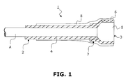
- FIG. 1 shows schematically an embodiment of an arrangement for electromagnetic shielding a connection between an electrical line and an electrical coupling element.
- FIG. 1 schematically the end of an electrical line 2 is shown.
- the line 2 comprises a wire A, which has an electrical conductor and a surrounding plastic insulation (not shown).
- the electrical conductor can be embodied, for example, as a solid conductor or as a stranded conductor. It may for example consist of copper or of aluminum or of an aluminum alloy.
- the carbon is, for example, in the form of fibers or threads, which are formed around the insulation of the core A, for example, by means of a known braiding machine as a braid or as a stranding can.
- the carbon can also be wrapped around the vein A as a prepared band.
- the carbon can be preformed as a hose and then pulled or pushed over the wire A. The hose can then be pulled down by tensile load to the plant on the insulation of the wire A.
- the line 2 is connected to an electrical coupling element 3.
- the schematically indicated coupling element 3 is for example a plug or a socket.
- the housing 5 of the coupling element 3 is surrounded by an electrically active shield 6 made of carbon. This carbon screen 6 can be applied to the coupling element 3 in a similar manner as in the line 2.
- the housing 5 of the coupling element 3 is advantageously made of insulating plastic.
- the shield 6 of the coupling element 3 is integrally connected to the screen 4 of the line 2.
- the two screens 4, 6 therefore form an overall shield, which encloses the connection between line 2 and coupling element 3 gapless.
- the cohesive connection of the screens 4, 6 of the line 2 and the coupling element 3 is achieved by a leiknownes adhesive.
- the adhesive is applied to the carbon fiber or thread structure of both screens 4, 6, so that they are impregnated with the adhesive.
- the two so impregnated umbrellas 4, 6 are then brought to abut each other.
- the screen 6 of the coupling element 3 can project slightly beyond the screen 4 of the line 2 and rest thereon, as in FIG Fig. 1 shown at reference number 7.
- the conductive adhesive may be, for example, an epoxy resin or a polyester resin which is mixed with conductive particles, for example nickel or carbon.
- the provided with the overall shield connection 1 between the line 2 and the coupling element 3 may further be surrounded by a layer 8 of insulating material.
- the layer 8 serves as protection against contact. It can, for example, be applied to compound 1 in a casting process. If the line 2 is a normally non-current-carrying cable, for example a grounding cable connected to the motor housing in a motor vehicle, then the insulating layer 8 can be dispensed with.
- the housing 5 of the coupling element 3 and the final layer 8 suitable materials include polyethylene, polypropylene, polyvinyl chloride and polyurethane.
Landscapes
- Engineering & Computer Science (AREA)
- Physics & Mathematics (AREA)
- Microelectronics & Electronic Packaging (AREA)
- Spectroscopy & Molecular Physics (AREA)
- Textile Engineering (AREA)
- Electromagnetism (AREA)
- Insulated Conductors (AREA)
- Details Of Connecting Devices For Male And Female Coupling (AREA)
- Shielding Devices Or Components To Electric Or Magnetic Fields (AREA)
- Body Structure For Vehicles (AREA)
Abstract
Description
- Die Erfindung bezieht sich auf eine Anordnung zur elektromagnetischen Abschirmung einer Verbindung zwischen einer elektrischen Leitung und einem mit der Leitung verbundenen elektrischen Kupplungselement, bei welcher die Leitung einen elektrisch wirksamen Schirm aus einem Kohlenstofffasern enthaltenden Kunststoff aufweist.
- Elektrische Leitungen, welche mindestens einen von einer Isolierung umgebenen elektrischen Leiter und einen die Isolierung umgebenden elektrisch wirksamen Schirm aufweisen, werden seit Jahren weltweit eingesetzt. Der elektrisch wirksame Schirm besteht überwiegend aus Kupferdrähten, welche als Geflecht oder als Umseilung um die Isolierung des Leiters herumgeformt sind.
- Besonders in Kraftfahrzeugen oder in Flugzeugen kommt eine große Anzahl solcher geschirmter Leitungen zum Einsatz, die beispielsweise in Kabelbäumen oder zu Kabelsätzen zu kompakten Einheiten zusammengefaßt sein können. Das Gewicht einer solchen elektrischen, geschirmten Leitung ist deshalb ausschlaggebend.
- Insbesondere in der Automobil- und Luftfahrtindustrie ist man deshalb bestrebt, das Gewicht der Leitungseinheiten zu senken, um hauptsächlich den Kraftstoffverbrauch zu reduzieren. Aus diesem Grunde ist es beispielsweise bekannt, für die elektrischen Leiter Aluminium oder Aluminiumlegierungen anstatt Kupfer einzusetzen oder Karosserien aus Kunststoff zu erzeugen. Aus der
DE 199 07 675 A1 ist es ebenfalls bekannt, den Schirm der elektrischen Leitung aus einem Faserverbundwerkstoff mit elektrisch leitenden Fasern, beispielsweise Kohlefasern, herzustellen. - Die geschirmten Leitungen sind in der Regel mit Kupplungselementen, wie Buchsen oder Steckern, verbunden, um an weitere elektrische Anlagen, beispielsweise an elektrische Bauteile, weiterführende Leitungen oder die Karosserie eines Kraftfahrzeugs angeschlossen werden zu können. Die Kupplungselemente können für störende elektromagnetische Felder, welche von außen auf die Leitung einwirken oder von der Leitung selbst erzeugt werden können, durchlässig sein. Die gewünschte elektromagnetische Verträglichkeit solcher Anordnungen kann dadurch beeinträchtigt werden.
- Der Erfindung liegt die Aufgabe zugrunde, eine Anordnung zur elektromagnetischen Abschirmung einer Verbindung zwischen einer elektrischen Leitung und einem Kupplungselement bereitzustellen, welche eine lückenlose Abschirmung von der Leitung bis über das Kupplungselement und die an diesen angeschlossenen weiteren elektrischen Anlagen gewährleistet.
- Diese Aufgabe wird gemäß der Erfindung dadurch gelöst, daß auch das Kupplungselement von einem elektrisch wirksamen Schirm aus einem Kohlenstofffasern enthaltenden Kunststoff umgeben ist, der stoffschlüssig mit dem Schirm der Leitung zu einem Gesamtschirm verbunden ist.
- Die erfindungsgemäße Anordnung erlaubt eine wirksame elektromagnetische Abschirmung der Verbindung zwischen Leitung und Kupplungselement, welche sicherstellt, daß die elektromagnetische Verträglichkeit der Verbindung innerhalb einer elektrischen Anlage nicht durch das Vorhandensein eines Kupplungselements beeinträchtigt wird. Die Schirme der Leitung und des Kupplungselements werden auf dasselbe Potential gelegt. Die erfindungsgemäße Anordnung weist außerdem mehrere Vorteile gegenüber einer konventionellen Anordnung mit metallischem Kabelschirm, metallischem Stecker- oder Buchsengehäuse und mit metallischen Kontaktelementen auf. Die Anordnung nach der Erfindung ist von besonders geringem Gewicht und deshalb mit Vorteil für die Nutzung in Kraftfahrzeugen und Luftfahrzeugen geeignet. Beispielsweise kann sie für Starkstromanwendungen in Hybrid- oder Elektrofahrzeugen eingesetzt werden. Außerdem ist die Anordnung sicher, langlebig und sehr kostengünstig.
- Ein Kohlenstofffasern enthaltender Kunststoff wird umgangssprachlich als Carbon bezeichnet. Diese Bezeichnung soll auch im Folgenden verwendet werden. Carbon ist ein Faser-Kunststoff-Verbundwerkstoff, bei welchem Kohlenstofffasern in eine Kunststoff-Matrix eingebettet sind. Der Kunststoff besteht beispielweise aus einem Duroplast, zum Beispiel Epoxidharz, aus einem Thermoplast oder aus Keramik. Carbon hat eine elektrische Leitfähigkeit, welche geringer als die des Kupfers ist, aber für eine wirksame elektromagnetische Abschirmung, insbesondere im Automobilbereich, ausreichend ist.
- In einer besonders bevorzugten Ausführungsform sind der Schirm des Kupplungselements und der Schirm des Kabels mittels eines elektrisch leitfähigen Klebemittels miteinander zu dem Gesamtschirm verbunden. Die Verwendung eines elektrisch leitfähigen Klebstoffs ist von besonderem Vorteil, weil dieser während der Herstellung des Gesamtschirms jeweils in die Matrixstruktur des Carbons der einzelnen Schirme eindringen kann, womit nach dem Aushärten des Klebstoffs ein besonders fester stoffschlüssiger Verbund zwischen den beiden Schirmen erreicht werden kann.
- Die erfindungsgemäße Anordnung wird in einer besonders bevorzugten Ausführungsform im Automobilbau eingesetzt, und zwar für elektrisch leitende Verbindungen innerhalb eines Kraftfahrzeugs.
- Die Anordnung gemäß der Erfindung wird anhand der Zeichnung erläutert.
Fig. 1 zeigt schematisch ein Ausführungsbeispiel einer Anordnung zur elektromagnetischen Abschirmung einer Verbindung zwischen einer elektrischen Leitung und einem elektrischen Kupplungselement. - In
Fig. 1 ist schematisch das Ende einer elektrischen Leitung 2 dargestellt. Die Leitung 2 umfaßt eine Ader A, welche einen elektrischen Leiter und eine diesen umgebende Isolierung aus Kunststoff (nicht dargestellt) aufweist. Der elektrische Leiter kann beispielsweise als Massivleiter oder als Litzenleiter ausgeführt sein. Er kann beispielsweise aus Kupfer oder aus Aluminium bzw. aus einer Aluminiumlegierung bestehen. - Um die Ader A herum ist ein elektrisch wirksamer Schirm 4 aus Carbon angebracht. Das Carbon liegt beispielweise in der Form von Fasern oder Fäden vor, die beispielsweise mittels einer bekannten Flechtmaschine als Geflecht oder als Umseilung um die Isolierung der Ader A herumgeformt werden können. Das Carbon kann auch als vorbereitetes Band um die Ader A herumgewickelt werden. Weiterhin kann das Carbon als Schlauch vorgeformt und anschließend über die Ader A gezogen bzw. geschoben werden. Der Schlauch kann dann durch Zugbelastung bis zur Anlage auf der Isolierung der Ader A heruntergezogen werden.
- Die Leitung 2 ist mit einem elektrischen Kupplungselement 3 verbunden. Das schematisch angedeutete Kupplungselement 3 ist beispielsweise ein Stecker oder eine Buchse. Erfindungsgemäß ist auch das Gehäuse 5 des Kupplungselements 3 von einem elektrisch wirksamen Schirm 6 aus Carbon umgeben. Dieser Carbon-Schirm 6 kann in ähnlicher Weise wie bei der Leitung 2 auf das Kupplungselement 3 aufgebracht werden. Das Gehäuse 5 des Kupplungselements 3 besteht mit Vorteil aus isolierendem Kunststoff.
- Der Schirm 6 des Kupplungselements 3 ist mit dem Schirm 4 der Leitung 2 stoffschlüssig verbunden. Die beiden Schirme 4, 6 bilden deshalb einen Gesamtschirm, welcher die Verbindung zwischen Leitung 2 und Kupplungselement 3 lückenlos umschließt.
- Nach einer besonders bevorzugten Ausführungsform der Erfindung wird die stoffschlüssige Verbindung der Schirme 4, 6 der Leitung 2 und des Kupplungselements 3 durch ein leifähiges Klebemittel erreicht. Das Klebemittel wird auf die Carbon-Faser- bzw. -Faden-Struktur beider Schirme 4, 6 aufgebracht, wodurch diese mit dem Klebemittel durchtränkt werden. Die beiden so durchtränkten Schirme 4, 6 werden anschließend zur Anlage aufeinander gebracht. Beispielsweise kann der Schirm 6 des Kupplungselements 3 etwas über den Schirm 4 der Leitung 2 überstehen und auf diesem aufliegen, wie in
Fig. 1 an der Bezugsnummer 7 dargestellt. Beim Aushärten des Klebemittels entsteht die stoffschlüssige Verbindung zwischen den beiden Schirmen 4, 6. Das leitfähige Klebemittel kann beispielsweise ein Epoxidharz oder ein Polyesterharz sein, welches mit leifähigen Partikeln, beispielsweise aus Nickel oder aus Kohlenstoff, versetzt ist. - Die mit dem Gesamtschirm versehene Verbindung 1 zwischen der Leitung 2 und dem Kupplungselement 3 kann weiterhin von einer Schicht 8 aus Isoliermaterial umgeben sein. Die Schicht 8 dient als Berührungsschutz. Sie kann beispielsweise in einem Gießprozeß auf die Verbindung 1 aufgetragen werden. Handelt es sich bei der Leitung 2 um ein normalerweise nicht stromführendes Kabel, beispielsweise um ein mit dem Motorgehäuse verbundenes Erdungskabel in einem Kraftfahrzeug, so kann auf die Isolierschicht 8 verzichtet werden.
- Für die Isolierung der Ader 2, das Gehäuse 5 des Kupplungselements 3 und die abschließende Schicht 8 geeignete Materialien sind beispielsweise Polyethylen, Polypropylen, Polyvinylchlorid und Polyurethan.
Claims (6)
- Anordnung zur elektromagnetischen Abschirmung einer Verbindung (1) zwischen einer elektrischen Leitung (2) und einem mit der Leitung (2) verbundenen elektrischen Kupplungselement (3), bei welcher die Leitung (2) einen elektrisch wirksamen Schirm (4) aus einem Kohlenstofffasern enthaltenden Kunststoff aufweist, dadurch gekennzeichnet, daß auch das Kupplungselement (3) von einem elektrisch wirksamen Schirm (6) aus einem Kohlenstofffasern enthaltenden Kunststoff umgeben ist, der stoffschlüssig mit dem Schirm (4) der Leitung (2) zu einem Gesamtschirm verbunden ist.
- Anordnung nach Anspruch 1, dadurch gekennzeichnet, daß der Schirm (6) des Kupplungselements (3) und der Schirm (4) der Leitung (2) mittels eines elektrisch leitfähigen Klebemittels verbunden sind.
- Anordnung nach einem der Ansprüche 1 und 2, dadurch gekennzeichnet, daß der Gesamtschirm von einer Schicht (8) aus Isoliermaterial umgeben ist.
- Anordnung nach einem der vorangehenden Ansprüche, dadurch gekennzeichnet, daß ein elektrischer Leiter der Leitung (2) aus Aluminium oder einer Aluminiumlegierung besteht.
- Anordnung nach einem der vorangehenden Ansprüche, dadurch gekennzeichnet, daß das Kupplungselement (3) ein Stecker oder eine Buchse ist.
- Verwendung einer Anordnung gemäß einem der Ansprüche 1 bis 5 für elektrisch leitende Verbindungen innerhalb eines Kraftfahrzeugs.
Priority Applications (3)
| Application Number | Priority Date | Filing Date | Title |
|---|---|---|---|
| EP14306011.9A EP2960990B1 (de) | 2014-06-26 | 2014-06-26 | Anordnung zur elektromagnetischen Abschirmung |
| ES14306011.9T ES2694802T3 (es) | 2014-06-26 | 2014-06-26 | Dispositivo para el blindaje electromagnético |
| US14/744,240 US9585294B2 (en) | 2014-06-26 | 2015-06-19 | Arrangement for electromagnetic screening |
Applications Claiming Priority (1)
| Application Number | Priority Date | Filing Date | Title |
|---|---|---|---|
| EP14306011.9A EP2960990B1 (de) | 2014-06-26 | 2014-06-26 | Anordnung zur elektromagnetischen Abschirmung |
Publications (2)
| Publication Number | Publication Date |
|---|---|
| EP2960990A1 true EP2960990A1 (de) | 2015-12-30 |
| EP2960990B1 EP2960990B1 (de) | 2018-08-08 |
Family
ID=51136400
Family Applications (1)
| Application Number | Title | Priority Date | Filing Date |
|---|---|---|---|
| EP14306011.9A Active EP2960990B1 (de) | 2014-06-26 | 2014-06-26 | Anordnung zur elektromagnetischen Abschirmung |
Country Status (3)
| Country | Link |
|---|---|
| US (1) | US9585294B2 (de) |
| EP (1) | EP2960990B1 (de) |
| ES (1) | ES2694802T3 (de) |
Families Citing this family (1)
| Publication number | Priority date | Publication date | Assignee | Title |
|---|---|---|---|---|
| EP3828036B1 (de) * | 2019-11-26 | 2026-01-28 | Aptiv Technologies AG | Elektrischer anschlusskasten und verfahren zur herstellung |
Citations (7)
| Publication number | Priority date | Publication date | Assignee | Title |
|---|---|---|---|---|
| DE3438660A1 (de) * | 1984-10-22 | 1986-04-24 | Almik Handelsgesellschaft für Industrieprodukte mbH, 8000 München | Abgeschirmtes, elektrisches kabel |
| DE19518541A1 (de) * | 1994-05-19 | 1995-11-23 | Yazaki Corp | Elektromagnetisch abschirmende Stoffzusammensetzung |
| DE19907675A1 (de) | 1999-02-23 | 2000-09-14 | Kreitmair Steck Wolfgang | Kabelschirm aus Faserverbundwerkstoffen mit hohem Anteil an elektrisch leitfähigen Fasern zur elektromagnetischen Abschirmung |
| US6861138B1 (en) * | 1998-07-04 | 2005-03-01 | Tesa Ag | Electrically conductive, thermoplastic, heat-activated adhesive film |
| EP1744409A2 (de) * | 2005-07-13 | 2007-01-17 | Sumitomo Wiring Systems, Ltd. | Abgeschirmter Verbinder und Verbindungsverfahren mit einem abgeschirmten Kabel |
| US20120319055A1 (en) * | 2009-12-23 | 2012-12-20 | Cheil Industries Inc. | Multi-functional Resin Composite Material and Molded Product Using the Same |
| WO2013047897A1 (en) * | 2011-09-27 | 2013-04-04 | Yazaki Corporation | Wire harness |
Family Cites Families (4)
| Publication number | Priority date | Publication date | Assignee | Title |
|---|---|---|---|---|
| GB2230151A (en) * | 1989-03-17 | 1990-10-10 | Plessey Telecomm | Electromagnetic shielding of cable termination |
| GB2346742A (en) * | 1999-02-19 | 2000-08-16 | Ibm | Cable screen connection method and sleeved cable grommet |
| US7692096B2 (en) * | 2007-12-07 | 2010-04-06 | Delphi Technologies, Inc. | Electromagnetically shielded cable |
| EP2517324B1 (de) * | 2009-12-24 | 2015-02-25 | Delphi International Operations Luxembourg S.à r.l. | Kabelverbindung |
-
2014
- 2014-06-26 ES ES14306011.9T patent/ES2694802T3/es active Active
- 2014-06-26 EP EP14306011.9A patent/EP2960990B1/de active Active
-
2015
- 2015-06-19 US US14/744,240 patent/US9585294B2/en not_active Expired - Fee Related
Patent Citations (7)
| Publication number | Priority date | Publication date | Assignee | Title |
|---|---|---|---|---|
| DE3438660A1 (de) * | 1984-10-22 | 1986-04-24 | Almik Handelsgesellschaft für Industrieprodukte mbH, 8000 München | Abgeschirmtes, elektrisches kabel |
| DE19518541A1 (de) * | 1994-05-19 | 1995-11-23 | Yazaki Corp | Elektromagnetisch abschirmende Stoffzusammensetzung |
| US6861138B1 (en) * | 1998-07-04 | 2005-03-01 | Tesa Ag | Electrically conductive, thermoplastic, heat-activated adhesive film |
| DE19907675A1 (de) | 1999-02-23 | 2000-09-14 | Kreitmair Steck Wolfgang | Kabelschirm aus Faserverbundwerkstoffen mit hohem Anteil an elektrisch leitfähigen Fasern zur elektromagnetischen Abschirmung |
| EP1744409A2 (de) * | 2005-07-13 | 2007-01-17 | Sumitomo Wiring Systems, Ltd. | Abgeschirmter Verbinder und Verbindungsverfahren mit einem abgeschirmten Kabel |
| US20120319055A1 (en) * | 2009-12-23 | 2012-12-20 | Cheil Industries Inc. | Multi-functional Resin Composite Material and Molded Product Using the Same |
| WO2013047897A1 (en) * | 2011-09-27 | 2013-04-04 | Yazaki Corporation | Wire harness |
Also Published As
| Publication number | Publication date |
|---|---|
| EP2960990B1 (de) | 2018-08-08 |
| US20150382516A1 (en) | 2015-12-31 |
| US9585294B2 (en) | 2017-02-28 |
| ES2694802T3 (es) | 2018-12-27 |
Similar Documents
| Publication | Publication Date | Title |
|---|---|---|
| DE102019107608B4 (de) | Verbundkabel | |
| EP2716437A1 (de) | Verbundbauteil mit elektrischen Leitungen | |
| EP1964133A1 (de) | Dreileiterkabel | |
| DE102018213095A1 (de) | Kabelbaum mit Elektrodrähte umgebendem Abschirmelement | |
| DE102022106349A1 (de) | Leiteranordnung für einen Energiespeicher eines Kraftfahrzeugs, Energiespeicher, Bordnetz und Kraftfahrzeug | |
| WO2016050408A1 (de) | Elektrische verbindungseinrichtung zum übertragen von elektrischer energie und/oder daten, bordnetz und kraftfahrzeug | |
| DE102014213973A1 (de) | Verbinderanordnung zum mechanisch flexiblen elektrischen Verbinden zweier Hochspannungskomponenten in einem Fahrzeug | |
| DE102014010346B3 (de) | Kraftfahrzeug mit innenverlegtem Hochvoltbordnetz | |
| DE102019107581B4 (de) | Verbundkabel | |
| DE2835400A1 (de) | Leitungskupplung zum durchverbinden von zwei elektrischen leitungen | |
| DE102017207211A1 (de) | Geschirmtes elektrisches Kabel | |
| EP2960990B1 (de) | Anordnung zur elektromagnetischen Abschirmung | |
| EP1163684A1 (de) | Kabelschirm aus faserverbundwerkstoffen | |
| DE102018209018A1 (de) | Hochvoltbordnetzanordnung für ein Kraftfahrzeug und Kraftfahrzeug | |
| DE102014220016A1 (de) | Vorrichtung zum elektromagnetisch verträglichen Verbinden von elektrischen Leitern mit Abschirmungsschicht | |
| EP2793239B1 (de) | Anordung mit mindestens einer elektrischen Leitung | |
| DE102011082179B4 (de) | Geschirmter Kabelbaum und Verfahren zu dessen Herstellung | |
| EP3057388A1 (de) | Gehäuse für hochvoltkomponenten | |
| DE102014217133B4 (de) | Schirmung und Hochvoltsystem | |
| DE102018000140A1 (de) | Abgeschirmter Kabelbaum und Verfahren zum Herstellen eines abgeschirmten Kabelbaums | |
| DE112017006372T5 (de) | Haltestruktur für Kabelbaum-Schutzelement | |
| DE102013227102A1 (de) | Elektrischer verbinder zum abschirmen von hochspannung | |
| DE102015206096B4 (de) | Geschirmtes Kabel mit Beilaufleiter und dessen Verwendung | |
| EP2993749A1 (de) | Anordnung zur elektrischen verbindung von elektrischen geräten | |
| DE1065910B (de) | Endenabschluß für isolierte Hochspannungsleiter |
Legal Events
| Date | Code | Title | Description |
|---|---|---|---|
| PUAI | Public reference made under article 153(3) epc to a published international application that has entered the european phase |
Free format text: ORIGINAL CODE: 0009012 |
|
| 17P | Request for examination filed |
Effective date: 20141223 |
|
| AK | Designated contracting states |
Kind code of ref document: A1 Designated state(s): AL AT BE BG CH CY CZ DE DK EE ES FI FR GB GR HR HU IE IS IT LI LT LU LV MC MK MT NL NO PL PT RO RS SE SI SK SM TR |
|
| AX | Request for extension of the european patent |
Extension state: BA ME |
|
| RAP1 | Party data changed (applicant data changed or rights of an application transferred) |
Owner name: NEXANS |
|
| REG | Reference to a national code |
Ref country code: DE Ref legal event code: R079 Ref document number: 502014009125 Country of ref document: DE Free format text: PREVIOUS MAIN CLASS: H01R0004040000 Ipc: H01R0013659100 |
|
| GRAP | Despatch of communication of intention to grant a patent |
Free format text: ORIGINAL CODE: EPIDOSNIGR1 |
|
| STAA | Information on the status of an ep patent application or granted ep patent |
Free format text: STATUS: GRANT OF PATENT IS INTENDED |
|
| RIC1 | Information provided on ipc code assigned before grant |
Ipc: H01B 3/30 20060101ALI20180119BHEP Ipc: H05K 9/00 20060101ALI20180119BHEP Ipc: H01R 13/6598 20110101ALI20180119BHEP Ipc: H01B 1/02 20060101ALI20180119BHEP Ipc: H02G 15/068 20060101ALN20180119BHEP Ipc: H01R 13/6591 20110101AFI20180119BHEP |
|
| INTG | Intention to grant announced |
Effective date: 20180212 |
|
| GRAA | (expected) grant |
Free format text: ORIGINAL CODE: 0009210 |
|
| STAA | Information on the status of an ep patent application or granted ep patent |
Free format text: STATUS: THE PATENT HAS BEEN GRANTED |
|
| GRAS | Grant fee paid |
Free format text: ORIGINAL CODE: EPIDOSNIGR3 |
|
| AK | Designated contracting states |
Kind code of ref document: B1 Designated state(s): AL AT BE BG CH CY CZ DE DK EE ES FI FR GB GR HR HU IE IS IT LI LT LU LV MC MK MT NL NO PL PT RO RS SE SI SK SM TR |
|
| REG | Reference to a national code |
Ref country code: GB Ref legal event code: FG4D Free format text: NOT ENGLISH |
|
| REG | Reference to a national code |
Ref country code: CH Ref legal event code: EP Ref country code: AT Ref legal event code: REF Ref document number: 1028069 Country of ref document: AT Kind code of ref document: T Effective date: 20180815 |
|
| REG | Reference to a national code |
Ref country code: IE Ref legal event code: FG4D Free format text: LANGUAGE OF EP DOCUMENT: GERMAN |
|
| REG | Reference to a national code |
Ref country code: DE Ref legal event code: R096 Ref document number: 502014009125 Country of ref document: DE |
|
| REG | Reference to a national code |
Ref country code: NL Ref legal event code: MP Effective date: 20180808 |
|
| REG | Reference to a national code |
Ref country code: LT Ref legal event code: MG4D |
|
| PG25 | Lapsed in a contracting state [announced via postgrant information from national office to epo] |
Ref country code: RS Free format text: LAPSE BECAUSE OF FAILURE TO SUBMIT A TRANSLATION OF THE DESCRIPTION OR TO PAY THE FEE WITHIN THE PRESCRIBED TIME-LIMIT Effective date: 20180808 Ref country code: IS Free format text: LAPSE BECAUSE OF FAILURE TO SUBMIT A TRANSLATION OF THE DESCRIPTION OR TO PAY THE FEE WITHIN THE PRESCRIBED TIME-LIMIT Effective date: 20181208 Ref country code: NL Free format text: LAPSE BECAUSE OF FAILURE TO SUBMIT A TRANSLATION OF THE DESCRIPTION OR TO PAY THE FEE WITHIN THE PRESCRIBED TIME-LIMIT Effective date: 20180808 Ref country code: LT Free format text: LAPSE BECAUSE OF FAILURE TO SUBMIT A TRANSLATION OF THE DESCRIPTION OR TO PAY THE FEE WITHIN THE PRESCRIBED TIME-LIMIT Effective date: 20180808 Ref country code: BG Free format text: LAPSE BECAUSE OF FAILURE TO SUBMIT A TRANSLATION OF THE DESCRIPTION OR TO PAY THE FEE WITHIN THE PRESCRIBED TIME-LIMIT Effective date: 20181108 Ref country code: SE Free format text: LAPSE BECAUSE OF FAILURE TO SUBMIT A TRANSLATION OF THE DESCRIPTION OR TO PAY THE FEE WITHIN THE PRESCRIBED TIME-LIMIT Effective date: 20180808 Ref country code: PL Free format text: LAPSE BECAUSE OF FAILURE TO SUBMIT A TRANSLATION OF THE DESCRIPTION OR TO PAY THE FEE WITHIN THE PRESCRIBED TIME-LIMIT Effective date: 20180808 Ref country code: FI Free format text: LAPSE BECAUSE OF FAILURE TO SUBMIT A TRANSLATION OF THE DESCRIPTION OR TO PAY THE FEE WITHIN THE PRESCRIBED TIME-LIMIT Effective date: 20180808 Ref country code: GR Free format text: LAPSE BECAUSE OF FAILURE TO SUBMIT A TRANSLATION OF THE DESCRIPTION OR TO PAY THE FEE WITHIN THE PRESCRIBED TIME-LIMIT Effective date: 20181109 Ref country code: NO Free format text: LAPSE BECAUSE OF FAILURE TO SUBMIT A TRANSLATION OF THE DESCRIPTION OR TO PAY THE FEE WITHIN THE PRESCRIBED TIME-LIMIT Effective date: 20181108 |
|
| PG25 | Lapsed in a contracting state [announced via postgrant information from national office to epo] |
Ref country code: LV Free format text: LAPSE BECAUSE OF FAILURE TO SUBMIT A TRANSLATION OF THE DESCRIPTION OR TO PAY THE FEE WITHIN THE PRESCRIBED TIME-LIMIT Effective date: 20180808 Ref country code: HR Free format text: LAPSE BECAUSE OF FAILURE TO SUBMIT A TRANSLATION OF THE DESCRIPTION OR TO PAY THE FEE WITHIN THE PRESCRIBED TIME-LIMIT Effective date: 20180808 Ref country code: AL Free format text: LAPSE BECAUSE OF FAILURE TO SUBMIT A TRANSLATION OF THE DESCRIPTION OR TO PAY THE FEE WITHIN THE PRESCRIBED TIME-LIMIT Effective date: 20180808 |
|
| PG25 | Lapsed in a contracting state [announced via postgrant information from national office to epo] |
Ref country code: RO Free format text: LAPSE BECAUSE OF FAILURE TO SUBMIT A TRANSLATION OF THE DESCRIPTION OR TO PAY THE FEE WITHIN THE PRESCRIBED TIME-LIMIT Effective date: 20180808 Ref country code: CZ Free format text: LAPSE BECAUSE OF FAILURE TO SUBMIT A TRANSLATION OF THE DESCRIPTION OR TO PAY THE FEE WITHIN THE PRESCRIBED TIME-LIMIT Effective date: 20180808 Ref country code: EE Free format text: LAPSE BECAUSE OF FAILURE TO SUBMIT A TRANSLATION OF THE DESCRIPTION OR TO PAY THE FEE WITHIN THE PRESCRIBED TIME-LIMIT Effective date: 20180808 |
|
| REG | Reference to a national code |
Ref country code: DE Ref legal event code: R097 Ref document number: 502014009125 Country of ref document: DE |
|
| PG25 | Lapsed in a contracting state [announced via postgrant information from national office to epo] |
Ref country code: SK Free format text: LAPSE BECAUSE OF FAILURE TO SUBMIT A TRANSLATION OF THE DESCRIPTION OR TO PAY THE FEE WITHIN THE PRESCRIBED TIME-LIMIT Effective date: 20180808 Ref country code: DK Free format text: LAPSE BECAUSE OF FAILURE TO SUBMIT A TRANSLATION OF THE DESCRIPTION OR TO PAY THE FEE WITHIN THE PRESCRIBED TIME-LIMIT Effective date: 20180808 Ref country code: SM Free format text: LAPSE BECAUSE OF FAILURE TO SUBMIT A TRANSLATION OF THE DESCRIPTION OR TO PAY THE FEE WITHIN THE PRESCRIBED TIME-LIMIT Effective date: 20180808 |
|
| PLBE | No opposition filed within time limit |
Free format text: ORIGINAL CODE: 0009261 |
|
| STAA | Information on the status of an ep patent application or granted ep patent |
Free format text: STATUS: NO OPPOSITION FILED WITHIN TIME LIMIT |
|
| 26N | No opposition filed |
Effective date: 20190509 |
|
| PG25 | Lapsed in a contracting state [announced via postgrant information from national office to epo] |
Ref country code: SI Free format text: LAPSE BECAUSE OF FAILURE TO SUBMIT A TRANSLATION OF THE DESCRIPTION OR TO PAY THE FEE WITHIN THE PRESCRIBED TIME-LIMIT Effective date: 20180808 |
|
| PG25 | Lapsed in a contracting state [announced via postgrant information from national office to epo] |
Ref country code: MC Free format text: LAPSE BECAUSE OF FAILURE TO SUBMIT A TRANSLATION OF THE DESCRIPTION OR TO PAY THE FEE WITHIN THE PRESCRIBED TIME-LIMIT Effective date: 20180808 |
|
| REG | Reference to a national code |
Ref country code: CH Ref legal event code: PL |
|
| REG | Reference to a national code |
Ref country code: BE Ref legal event code: MM Effective date: 20190630 |
|
| PG25 | Lapsed in a contracting state [announced via postgrant information from national office to epo] |
Ref country code: TR Free format text: LAPSE BECAUSE OF FAILURE TO SUBMIT A TRANSLATION OF THE DESCRIPTION OR TO PAY THE FEE WITHIN THE PRESCRIBED TIME-LIMIT Effective date: 20180808 |
|
| PG25 | Lapsed in a contracting state [announced via postgrant information from national office to epo] |
Ref country code: IE Free format text: LAPSE BECAUSE OF NON-PAYMENT OF DUE FEES Effective date: 20190626 |
|
| PG25 | Lapsed in a contracting state [announced via postgrant information from national office to epo] |
Ref country code: LU Free format text: LAPSE BECAUSE OF NON-PAYMENT OF DUE FEES Effective date: 20190626 Ref country code: CH Free format text: LAPSE BECAUSE OF NON-PAYMENT OF DUE FEES Effective date: 20190630 Ref country code: LI Free format text: LAPSE BECAUSE OF NON-PAYMENT OF DUE FEES Effective date: 20190630 Ref country code: BE Free format text: LAPSE BECAUSE OF NON-PAYMENT OF DUE FEES Effective date: 20190630 |
|
| PG25 | Lapsed in a contracting state [announced via postgrant information from national office to epo] |
Ref country code: PT Free format text: LAPSE BECAUSE OF FAILURE TO SUBMIT A TRANSLATION OF THE DESCRIPTION OR TO PAY THE FEE WITHIN THE PRESCRIBED TIME-LIMIT Effective date: 20181208 |
|
| REG | Reference to a national code |
Ref country code: AT Ref legal event code: MM01 Ref document number: 1028069 Country of ref document: AT Kind code of ref document: T Effective date: 20190626 |
|
| PG25 | Lapsed in a contracting state [announced via postgrant information from national office to epo] |
Ref country code: AT Free format text: LAPSE BECAUSE OF NON-PAYMENT OF DUE FEES Effective date: 20190626 |
|
| PG25 | Lapsed in a contracting state [announced via postgrant information from national office to epo] |
Ref country code: CY Free format text: LAPSE BECAUSE OF FAILURE TO SUBMIT A TRANSLATION OF THE DESCRIPTION OR TO PAY THE FEE WITHIN THE PRESCRIBED TIME-LIMIT Effective date: 20180808 |
|
| PG25 | Lapsed in a contracting state [announced via postgrant information from national office to epo] |
Ref country code: MT Free format text: LAPSE BECAUSE OF FAILURE TO SUBMIT A TRANSLATION OF THE DESCRIPTION OR TO PAY THE FEE WITHIN THE PRESCRIBED TIME-LIMIT Effective date: 20180808 Ref country code: HU Free format text: LAPSE BECAUSE OF FAILURE TO SUBMIT A TRANSLATION OF THE DESCRIPTION OR TO PAY THE FEE WITHIN THE PRESCRIBED TIME-LIMIT; INVALID AB INITIO Effective date: 20140626 |
|
| PG25 | Lapsed in a contracting state [announced via postgrant information from national office to epo] |
Ref country code: MK Free format text: LAPSE BECAUSE OF FAILURE TO SUBMIT A TRANSLATION OF THE DESCRIPTION OR TO PAY THE FEE WITHIN THE PRESCRIBED TIME-LIMIT Effective date: 20180808 |
|
| PGFP | Annual fee paid to national office [announced via postgrant information from national office to epo] |
Ref country code: ES Payment date: 20230829 Year of fee payment: 10 |
|
| REG | Reference to a national code |
Ref country code: ES Ref legal event code: FD2A Effective date: 20250804 |
|
| PG25 | Lapsed in a contracting state [announced via postgrant information from national office to epo] |
Ref country code: ES Free format text: LAPSE BECAUSE OF NON-PAYMENT OF DUE FEES Effective date: 20240627 |
|
| PGFP | Annual fee paid to national office [announced via postgrant information from national office to epo] |
Ref country code: GB Payment date: 20260625 Year of fee payment: 13 |
|
| PGFP | Annual fee paid to national office [announced via postgrant information from national office to epo] |
Ref country code: IT Payment date: 20260623 Year of fee payment: 13 |
|
| PGFP | Annual fee paid to national office [announced via postgrant information from national office to epo] |
Ref country code: DE Payment date: 20260622 Year of fee payment: 13 |
|
| PGFP | Annual fee paid to national office [announced via postgrant information from national office to epo] |
Ref country code: FR Payment date: 20260626 Year of fee payment: 13 |