EP2960923A1 - Switching arrangement - Google Patents
Switching arrangement Download PDFInfo
- Publication number
- EP2960923A1 EP2960923A1 EP15173735.0A EP15173735A EP2960923A1 EP 2960923 A1 EP2960923 A1 EP 2960923A1 EP 15173735 A EP15173735 A EP 15173735A EP 2960923 A1 EP2960923 A1 EP 2960923A1
- Authority
- EP
- European Patent Office
- Prior art keywords
- detector
- switching device
- switching
- housing
- voltage
- Prior art date
- Legal status (The legal status is an assumption and is not a legal conclusion. Google has not performed a legal analysis and makes no representation as to the accuracy of the status listed.)
- Granted
Links
Images


Classifications
-
- H—ELECTRICITY
- H01—ELECTRIC ELEMENTS
- H01H—ELECTRIC SWITCHES; RELAYS; SELECTORS; EMERGENCY PROTECTIVE DEVICES
- H01H9/00—Details of switching devices, not covered by groups H01H1/00 - H01H7/00
- H01H9/16—Indicators for switching condition, e.g. "on" or "off"
-
- H—ELECTRICITY
- H01—ELECTRIC ELEMENTS
- H01F—MAGNETS; INDUCTANCES; TRANSFORMERS; SELECTION OF MATERIALS FOR THEIR MAGNETIC PROPERTIES
- H01F7/00—Magnets
- H01F7/06—Electromagnets; Actuators including electromagnets
- H01F7/08—Electromagnets; Actuators including electromagnets with armatures
- H01F7/18—Circuit arrangements for obtaining desired operating characteristics, e.g. for slow operation, for sequential energisation of windings, for high-speed energisation of windings
- H01F7/1844—Monitoring or fail-safe circuits
-
- G—PHYSICS
- G01—MEASURING; TESTING
- G01R—MEASURING ELECTRIC VARIABLES; MEASURING MAGNETIC VARIABLES
- G01R31/00—Arrangements for testing electric properties; Arrangements for locating electric faults; Arrangements for electrical testing characterised by what is being tested not provided for elsewhere
- G01R31/327—Testing of circuit interrupters, switches or circuit-breakers
- G01R31/3271—Testing of circuit interrupters, switches or circuit-breakers of high voltage or medium voltage devices
-
- G—PHYSICS
- G01—MEASURING; TESTING
- G01S—RADIO DIRECTION-FINDING; RADIO NAVIGATION; DETERMINING DISTANCE OR VELOCITY BY USE OF RADIO WAVES; LOCATING OR PRESENCE-DETECTING BY USE OF THE REFLECTION OR RERADIATION OF RADIO WAVES; ANALOGOUS ARRANGEMENTS USING OTHER WAVES
- G01S17/00—Systems using the reflection or reradiation of electromagnetic waves other than radio waves, e.g. lidar systems
- G01S17/02—Systems using the reflection of electromagnetic waves other than radio waves
- G01S17/06—Systems determining position data of a target
-
- H—ELECTRICITY
- H01—ELECTRIC ELEMENTS
- H01H—ELECTRIC SWITCHES; RELAYS; SELECTORS; EMERGENCY PROTECTIVE DEVICES
- H01H1/00—Contacts
- H01H1/12—Contacts characterised by the manner in which co-operating contacts engage
- H01H1/14—Contacts characterised by the manner in which co-operating contacts engage by abutting
- H01H1/20—Bridging contacts
-
- H—ELECTRICITY
- H01—ELECTRIC ELEMENTS
- H01H—ELECTRIC SWITCHES; RELAYS; SELECTORS; EMERGENCY PROTECTIVE DEVICES
- H01H50/00—Details of electromagnetic relays
- H01H50/08—Indicators; Distinguishing marks
-
- H—ELECTRICITY
- H01—ELECTRIC ELEMENTS
- H01H—ELECTRIC SWITCHES; RELAYS; SELECTORS; EMERGENCY PROTECTIVE DEVICES
- H01H71/00—Details of the protective switches or relays covered by groups H01H73/00 - H01H83/00
- H01H71/04—Means for indicating condition of the switching device
-
- H—ELECTRICITY
- H01—ELECTRIC ELEMENTS
- H01H—ELECTRIC SWITCHES; RELAYS; SELECTORS; EMERGENCY PROTECTIVE DEVICES
- H01H1/00—Contacts
- H01H1/0015—Means for testing or for inspecting contacts, e.g. wear indicator
-
- H—ELECTRICITY
- H01—ELECTRIC ELEMENTS
- H01H—ELECTRIC SWITCHES; RELAYS; SELECTORS; EMERGENCY PROTECTIVE DEVICES
- H01H71/00—Details of the protective switches or relays covered by groups H01H73/00 - H01H83/00
- H01H71/04—Means for indicating condition of the switching device
- H01H2071/048—Means for indicating condition of the switching device containing non-mechanical switch position sensor, e.g. HALL sensor
Definitions
- the invention relates to a switching arrangement, in particular for the high-voltage and/or high-current region, with two contacts and a switching device, which can be moved into a separated position in which the contacts are electrically separated from one another.
- Such switching arrangements are used, for example, in electrically operated cars. In order to ensure that, for example, no dangerous voltages are present in the case of maintenance work, it is necessary to be able to detect that the switching arrangement is adequately insulated.
- auxiliary relays serve to couple measurement devices to the circuit. This is, however, very complex.
- the position of the switching device is sensed with a micro-switch. This is, however, unreliable since parts of the micro-switch can break down and the switching arrangement can be influenced as a result, so that it no longer functions reliably. Moreover, such a solution is often not permissible since high voltage can be present at the micro-switch under certain circumstances.
- the object of the invention is to provide a solution with which it is possible to easily and reliably ascertain whether the switching arrangement is insulated.
- a switching arrangement according to the invention comprises a detector with which the presence of the switching device in the separated position can be detected in a contact-free manner.
- the solution according to the invention has the advantage that it is simpler than the measurement known from the prior art with auxiliary relays. Moreover, the contactless measurement prevents high voltages or current from being able to be transmitted to the detector. Moreover, a defect in the detector does not lead to impairments of the switch. The solution according to the invention is therefore also more reliable.
- the switching device can be movable into a bridging position in which the contacts are connected to one another in an electrically conductive manner by the switching device.
- the detector can be configured so that the presence of the switching device in the bridging position can be detected in a contact-free manner with said detector.
- the presence of the switching device in the bridging position is detected by a contact-free measurement of the position of the switching device.
- the detector can be configured so that it can detect a high or infinite number of intermediate positions so that a determination of the position of the switching device in a continuous or quasi-continuous region between bridging position and separated position is possible.
- the detector allows a sufficiently high resolution of the position, wear and tear of the switching device or the contacts which occurs over longer periods of time can thus also be detected with it. As a result, for example, wear can be identified. If there is an appropriately high temporal resolution of the detector, such wear measurement could also be carried out by measuring the position of the switching device or of an element which drives the switching device at specific points in time. Such points in time are in particular the establishment of contact between the contacts by the switching device and the occupation of the end position of the switching device and/or of an element which drives the switching device.
- the contacts can be arranged in a contact switching chamber. As a result, protection of the contacts from influences from the outside and protection of other elements from the contacts can be achieved.
- the switching arrangement can be a relay or a protection device.
- the switching arrangement can have a signal-permeable wall region which is permeable for the signals which can be detected by the detector.
- This can, for example, be a recess or opening in a wall or part of a wall or form a wall.
- a wall can be a housing wall, for example, an outer or inner housing wall.
- the switching device can comprise a drive for a contact bridge.
- the detector can be directed towards the drive. A detection of the separated state can be carried out without having to record the contact bridge itself.
- the detector can be arranged on the side of the drive which faces away from the contacts. A wall region can be present between the detector and the drive, which wall region is permeable for the signals which can be detected by the detector. This enables a simple and compact design.
- the drive can be arranged between the contact bridge and the wall region which is permeable for the signals which can be detected by the detector.
- the drive can be arranged between the contact bridge and the detector.
- the detector can be arranged on the side of the switching arrangement which lies opposite the contact bridge in relation to the drive.
- the switching device can comprise an armature arranged in a coil and the position of the armature can be able to be detected with the detector in a contact-free manner.
- the armature can be connected in a positive locking manner, in particular rigidly to the rest of the switching device so that the position of the switching device can be concluded from the position of the armature and in particular the presence of the switching device in the separated position can be identified.
- the armature can serve to drive the switching device.
- the coil can attempt to move the switching device into the separated position or into the bridging position or out thereof.
- the armature therefore not only satisfies the function that it transmits the force and/or the movement to the switching device, but rather simultaneously serves as an indicator element for the position of the switching device.
- the signal-permeable wall region can be arranged in the region of the drive, in particular in the region of the coil. For example, it can be arranged in the region of a rear side of a coil.
- An element of the drive coupled to the switching device, in particular to the contact bridge, can be able to be sensed by the signal-permeable wall region.
- the element can be sensed in particular directly, i.e. without intermediate elements. This enables a simple construction.
- the detector can be arranged outside and the contacts inside a housing.
- the housing can comprise a contact switching chamber. If the detector is not arranged in the same housing, in particular not in or close to a contact switching chamber, it is not exposed to the loads which occur as a result of the switching, for example, arc formation. As a result of this, the detector is protected and can be used for longer.
- the detector can be designed without a housing.
- the detector can be arranged outside a housing in which the contacts are arranged. It can, for example, be accommodated in a separate housing or have its own housing. This can enable easy separation of the contacts from the detector.
- the position of the switching device can be permanently monitored.
- a special measurement step can be omitted, as a result of which operation is simplified.
- the switching arrangement can comprise a housing.
- the housing can in turn comprise a high-voltage region and a low-voltage region, wherein the contacts are arranged in the high-voltage region and the detector is arranged in the low-voltage region.
- the housing can be as a whole gas- and/or liquid-impervious and prevent the ingress of dust.
- the housing can be high-voltage-impervious so that no dangerous high voltages can escape out of the housing.
- the high-voltage region and the low-voltage region can be connected to one another.
- both regions can be situated in a single chamber.
- the contacts can thus be arranged on one side of the housing and the detector can be arranged on an opposite side of the housing in each case internally in the housing so that the detector can detect the position of the switching device without, however, having a direct contact to the switching device.
- the high-voltage region and the low-voltage region can be separated from one another by a gas- and/or liquid-impervious, signal-permeable wall region.
- a gas- and/or liquid-impervious, signal-permeable wall region can prevent the penetration of high voltage into the low-voltage region.
- the wall region is simultaneously permeable for the signals used in the contact-free measurement with the detector.
- the wall region can be permeable for the electromagnetic waves. It can be produced from a dielectric medium or from a magnetically permeable material. This can be, for example, a transparent window or a transparent partition if the measurement is carried out optically
- the wall region can be magnetically permeable or conductive.
- the signal-permeable wall region can be a partition which divides an otherwise open chamber into two parts.
- the signal-permeable wall region is a window of a wall which separates the high-voltage region from the low-voltage region from one another.
- the high-voltage region and the low-voltage region are reliably separated from one another so that the high voltages cannot penetrate into the low-voltage region. The risk of damage to electric elements or injuries to users is therefore reduced.
- the contacts are arranged in a high-voltage housing and/or the detector is arranged in a low-voltage housing, the high-voltage housing and/or the low-voltage housing being in each case gas- and/or liquid-impervious.
- This can therefore involve separate housings which reduce in each case themselves a hazard to users as a result of escaping voltages.
- wall regions can be present on the high-voltage housing and/or on the low-voltage housing which allow the penetration of the measurement signal.
- windows can be present in walls or entire walls or the entire housing can be configured to be permeable for the signal.
- the contacts can be arranged in a high-voltage housing and the detector can be arranged in a low-voltage housing which can be joined together with the high-voltage housing.
- the high-voltage housing is gas-and/or liquid-impervious in the joined-together state.
- the high-voltage housing does not have to be gas- or liquid-impervious in the non-joined together state, but rather can only become gas- and/or liquid-impervious by joining together with the low-voltage housing. Manufacture and maintenance are simplified in the case of such a configuration.
- a gas- and/or liquid-impervious configuration of the housing(s) or of the contact switching chamber is not always necessary. Above all, a voltage-impervious, in particular high-voltage impervious configuration is advantageous. A dust-impervious configuration is furthermore advantageous.
- the high-voltage housing together with the low-voltage housing in the joined-together state forms a gas- and/or liquid-impervious entire housing.
- the high-voltage housing and/or the low-voltage housing do not have to be gas- and/or liquid-impervious in the as yet non-joined-together state.
- Such sealing can only be achieved by joining together the two housings.
- the manufacturing method is also simplified in the case of such a configuration.
- the housing is formed at least partially by walls of the contact switching chamber and at least partially by walls of a detector chamber. As a result, the number of components required is reduced.
- the switching arrangement can have adjustment means. These can enable, for example, the position of the detector in all three spatial directions and along different angles.
- the detector which performs contact-free measurement can be an optical sensor.
- this can be a light barrier, in particular a reflection light barrier which detects the presence of the switching element in the separated position.
- a detector can comprise in particular a transmitter and a receiver.
- sensors are also possible, for example, ultrasound sensors or a sensor which detects the presence of a magnetically conductive part of the switching element.
- the detector which performs contact-free measurement can be a magnetic field sensor.
- a magnetic field sensor can detect the strength or the change in the strength of a magnetic field.
- the magnetic field can be generated, for example, by an attached magnet, in particular a permanent magnet. This can in particular be a Hall sensor. If further magnetic field-generating elements, such as a coil, are present, this can lead to the magnetic field sensor only being used for detection if these elements are not activated, for example, if the coil is current-free. This can be, for example, in a separated position.
- the detector can have a signal output at which a first signal is emitted if the switching device is located in the separated position and at which at least one further signal which is different from the first signal is transmitted if the switching device is not located in the separated position.
- a second signal which is different from the first and further signals can be transmitted at the signal output if the switching device is located in a bridging position in which the contacts are connected to one another by the switching device. As a result, positive feedback that the switching device is located in the bridging position can be generated.
- Further signals can be present at the signal output, in particular a continuous or quasi-continuous signal region can be present between the first signal and the second signal so that, for example, a position of the switching device can be determined more accurately. This allows more accurate monitoring of the movement of the switching device.
- the solution according to the invention also comprises a switch for a switching arrangement or switching assembly according to the invention.
- a switch is configured to enable measurement with a detector which performs contact-free measurement.
- a signal-permeable wall region can be present which enables a measurement signal to pass through.
- a wall region can be an opening or a window.
- the wall region can be gas- and/or liquid-impervious and/or high-voltage-impervious so that no high voltage can escape.
- a window can be fitted in an opening of a wall.
- the detection can be carried out through a housing wall.
- a switching arrangement 1 is represented in Fig. 1 .
- Switching arrangement 1 comprises a switch 2 with two contacts 3 which are arranged in a contact switching chamber 4.
- a switching device 5 serves to establish or disconnect an electric connection between the two contacts 3.
- switching device 5 is movable between separated position I represented in Fig. 1 , in which contacts 3 are electrically separated from one another, and a bridging position, in which contacts 3 are connected to one another in an electrically conductive manner by switching device 5.
- Switching device 5 comprises a contact bridge 18 and an armature 6.
- Armature 6 is arranged in a coil 7 which is represented partially cut away in Fig. 1 in order to enable a view of further elements.
- armature 6, and thus switching device 5 is moved in or counter to switching direction S and switch 2 is thus electrically conductive or electrically insulating between contacts 3.
- Armature 6 represents a part of a drive 20 for contact bridge 20.
- switching arrangement 1 has a detector 8 which detects the position of switching device 5. In particular, it detects whether switching device 5 is in separated position I. For this purpose, detector 8 is aligned towards the region of a rear side 61 of armature 6.
- the detector is a detector 8 which performs optical measurement 8.
- Detector 8 is designed as a reflection light barrier.
- Detector 8 comprises a transmitter 81 which transmits a light beam 82.
- Light beam 82 is reflected in different ways in the region of rear side 61 of armature 6 depending on the position of armature 6 and of rear side 61 so that, depending on the position of rear side 61, more or less light of light beam 82 is reflected into a receiver 83.
- Receiver 83 converts the light into an electric signal so that downstream electronics (not represented) can evaluate whether switching device 5 is in separated position I or not.
- Detector 8 can also be configured so that the presence of switching device 5 in the bridging position is detected.
- the movement of switching device 5 and/or the movement of armature 6 can be measured over the entire armature stroke with temporal and/or spatial resolution.
- Such a measurement can be used, for example, to identify wear of the switching device.
- wear can be exhibited, for example, in that the stroke of armature 6 and/or switching device 5 becomes longer and/or is displaced along switching direction S.
- a changed movement profile can also indicate wear.
- Such a changed movement profile can be identified, for example, by contrasting earlier and current location/time characteristics.
- the position of armature 6 at the point in time of closing of contacts 3 and the end location of armature 6 can be measured. Wear can then be concluded from this data since this length is extended with increasing service life.
- housing 9 of switch 2 has a signal-permeable wall region 10 which is configured as an opening or recess in the configuration according to Fig. 1 .
- a signal-permeable wall region 10 can, for example, also consist of a transparent window.
- wall region 10 allows the signals required for measurement to pass through, but enables sealing of housing 9, in particular a gas- and/or liquid-impervious sealing and high-voltage-impervious sealing.
- Signal-permeable wall region 10 is arranged on a rear side of housing 9.
- Drive 20 lies between contact bridge 18 and wall region 10.
- the drive lies between contact bridge 18 and detector 8.
- Drive 20 lies outside housing 9.
- Gas- and liquid-impervious sealing is not absolutely essential. Voltage-impervious, in particular high-voltage-impervious sealing is usually sufficient. Dust-impervious sealing is also advantageous.
- Wall region 10 lies in the region of coil 7, i.e. in the region of drive 20. It allows a direct sensing of an element of drive 20, namely of armature 6, without further intermediate elements.
- detector 8 and switch 2 are separated from one another. Both are located in each case in their own housings.
- detector 8 and switch 2 can be unified in a single housing 9.
- Such as housing can as a whole be gas- and/or liquid- and/or high-voltage-impervious.
- the contacts can be arranged in a first housing and detector 8 can be arranged in a second housing 9.
- the housing with contacts 3 is a high-voltage housing
- the housing with detector 8 is a low-voltage housing.
- the two housings can be able to be joined together so that the high-voltage housing is sealed off in a high-voltage-proof manner only in the joined-together state, for example, because open points, for example, a wall region 10 can also be sealed off by the low-voltage housing.
- the high-voltage housing and the low-voltage housing in the joined-together state can produce an entire housing which is gas- and/or liquid- and/or high-voltage-impervious, while in the non-joined-together state at least one housing is not gas- and/or liquid- and/or voltage-impervious.
- the detector is directed towards drive 20. A direct detection of the position of contact bridge 18 is not necessary.
- Detector 8 is arranged on the side of drive 20 which faces away from contacts 3.
- a wall region 10 which is permeable for the signals of the measurement with detector 8 is arranged between detector 8 and drive 20.
- Switching device 5 again connects contacts 3 in an electrically conductive manner if it is located in a bridging position, not represented.
- switching element 5 comprises an armature 6 and a contact bridge 18 connected thereto.
- the connection here is indirectly via a connection element 11.
- a spring 12 presses the contact bridge against an upper side of connection element 11 or, in the bridging state, against contacts 3.
- Armature 6 is arranged in friction bearings 13 which are arranged in a coil 7.
- a spring 14 prestresses the armature in the direction of separated position I.
- Coil 7 comprises a coil body 15 and windings 16 which are only represented schematically.
- Signal-permeable wall region 10, which is configured here as an opening in housing 9, is particularly apparent.
- the position of armature 6 and thus of switching device 5 can be detected in a contact-free manner through wall region 10. As a result of the contact-free sensing, it is ensured that no high voltage is transmitted to the detector.
- Detector 8 used here comprises a sensor which can measure a magnetic field. This can involve, for example, a Hall sensor. Depending on the position of armature 6, a magnetic circuit 17 is closed or open so that the Hall sensor measures a different direction and/or intensity of magnetic field M. The position of the armature and of switching element 5 connected thereto can thus also be deduced. Again, the measurement is carried out in a contact-free manner.
Landscapes
- Physics & Mathematics (AREA)
- Electromagnetism (AREA)
- Engineering & Computer Science (AREA)
- General Physics & Mathematics (AREA)
- Computer Networks & Wireless Communication (AREA)
- Radar, Positioning & Navigation (AREA)
- Remote Sensing (AREA)
- Power Engineering (AREA)
- Measurement Of Length, Angles, Or The Like Using Electric Or Magnetic Means (AREA)
- Keying Circuit Devices (AREA)
- Measuring Magnetic Variables (AREA)
- Contacts (AREA)
Abstract
Description
- The invention relates to a switching arrangement, in particular for the high-voltage and/or high-current region, with two contacts and a switching device, which can be moved into a separated position in which the contacts are electrically separated from one another.
- Such switching arrangements are used, for example, in electrically operated cars. In order to ensure that, for example, no dangerous voltages are present in the case of maintenance work, it is necessary to be able to detect that the switching arrangement is adequately insulated.
- In the case of a previous method, measurement is thereby carried out directly in the electric circuit. In this case, auxiliary relays serve to couple measurement devices to the circuit. This is, however, very complex.
- In the case of a different previous method, the position of the switching device is sensed with a micro-switch. This is, however, unreliable since parts of the micro-switch can break down and the switching arrangement can be influenced as a result, so that it no longer functions reliably. Moreover, such a solution is often not permissible since high voltage can be present at the micro-switch under certain circumstances.
- The object of the invention is to provide a solution with which it is possible to easily and reliably ascertain whether the switching arrangement is insulated.
- According to the invention, this is achieved in that the presence of the switching device in the separated position is detected by a contact-free measurement of the position of the switching device. For this purpose, a switching arrangement according to the invention comprises a detector with which the presence of the switching device in the separated position can be detected in a contact-free manner.
- The solution according to the invention has the advantage that it is simpler than the measurement known from the prior art with auxiliary relays. Moreover, the contactless measurement prevents high voltages or current from being able to be transmitted to the detector. Moreover, a defect in the detector does not lead to impairments of the switch. The solution according to the invention is therefore also more reliable.
- The solution according to the invention can be further improved with the following configurations and further developments which are themselves each advantageous and which can be combined with one another as desired.
- The switching device can be movable into a bridging position in which the contacts are connected to one another in an electrically conductive manner by the switching device. In order to also be able to ascertain whether the switching device is located in the bridging position, the detector can be configured so that the presence of the switching device in the bridging position can be detected in a contact-free manner with said detector. In a corresponding method, the presence of the switching device in the bridging position is detected by a contact-free measurement of the position of the switching device.
- Not only the presence in the separated position and/or the bridging position, but rather also in the positions lying therebetween can be detected with an appropriately configured detector. In particular, the detector can be configured so that it can detect a high or infinite number of intermediate positions so that a determination of the position of the switching device in a continuous or quasi-continuous region between bridging position and separated position is possible.
- If the detector allows a sufficiently high resolution of the position, wear and tear of the switching device or the contacts which occurs over longer periods of time can thus also be detected with it. As a result, for example, wear can be identified. If there is an appropriately high temporal resolution of the detector, such wear measurement could also be carried out by measuring the position of the switching device or of an element which drives the switching device at specific points in time. Such points in time are in particular the establishment of contact between the contacts by the switching device and the occupation of the end position of the switching device and/or of an element which drives the switching device.
- The contacts can be arranged in a contact switching chamber. As a result, protection of the contacts from influences from the outside and protection of other elements from the contacts can be achieved. The switching arrangement can be a relay or a protection device.
- The switching arrangement can have a signal-permeable wall region which is permeable for the signals which can be detected by the detector. This can, for example, be a recess or opening in a wall or part of a wall or form a wall. Such a wall can be a housing wall, for example, an outer or inner housing wall.
- The switching device can comprise a drive for a contact bridge. The detector can be directed towards the drive. A detection of the separated state can be carried out without having to record the contact bridge itself. In particular, the detector can be arranged on the side of the drive which faces away from the contacts. A wall region can be present between the detector and the drive, which wall region is permeable for the signals which can be detected by the detector. This enables a simple and compact design.
- The drive can be arranged between the contact bridge and the wall region which is permeable for the signals which can be detected by the detector. The drive can be arranged between the contact bridge and the detector. The detector can be arranged on the side of the switching arrangement which lies opposite the contact bridge in relation to the drive. As a result, in each case a compact configuration can be enabled.
- The switching device can comprise an armature arranged in a coil and the position of the armature can be able to be detected with the detector in a contact-free manner. The armature can be connected in a positive locking manner, in particular rigidly to the rest of the switching device so that the position of the switching device can be concluded from the position of the armature and in particular the presence of the switching device in the separated position can be identified. The armature can serve to drive the switching device. Depending on whether a current flows through the coil and on which strength and orientation the current has, the coil can attempt to move the switching device into the separated position or into the bridging position or out thereof. Here, the armature therefore not only satisfies the function that it transmits the force and/or the movement to the switching device, but rather simultaneously serves as an indicator element for the position of the switching device.
- The signal-permeable wall region can be arranged in the region of the drive, in particular in the region of the coil. For example, it can be arranged in the region of a rear side of a coil. An element of the drive coupled to the switching device, in particular to the contact bridge, can be able to be sensed by the signal-permeable wall region. The element can be sensed in particular directly, i.e. without intermediate elements. This enables a simple construction.
- The detector can be arranged outside and the contacts inside a housing. In particular, the housing can comprise a contact switching chamber. If the detector is not arranged in the same housing, in particular not in or close to a contact switching chamber, it is not exposed to the loads which occur as a result of the switching, for example, arc formation. As a result of this, the detector is protected and can be used for longer. The detector can be designed without a housing. The detector can be arranged outside a housing in which the contacts are arranged. It can, for example, be accommodated in a separate housing or have its own housing. This can enable easy separation of the contacts from the detector.
- The position of the switching device can be permanently monitored. A special measurement step can be omitted, as a result of which operation is simplified.
- The switching arrangement can comprise a housing. The housing can in turn comprise a high-voltage region and a low-voltage region, wherein the contacts are arranged in the high-voltage region and the detector is arranged in the low-voltage region. As a result, a separation of high voltage and low voltage can be achieved. The housing can be as a whole gas- and/or liquid-impervious and prevent the ingress of dust. Moreover, the housing can be high-voltage-impervious so that no dangerous high voltages can escape out of the housing.
- In a first configuration, the high-voltage region and the low-voltage region can be connected to one another. For example, both regions can be situated in a single chamber. For example, the contacts can thus be arranged on one side of the housing and the detector can be arranged on an opposite side of the housing in each case internally in the housing so that the detector can detect the position of the switching device without, however, having a direct contact to the switching device.
- In a further configuration, the high-voltage region and the low-voltage region can be separated from one another by a gas- and/or liquid-impervious, signal-permeable wall region. In particular, such a wall region can prevent the penetration of high voltage into the low-voltage region. The wall region is simultaneously permeable for the signals used in the contact-free measurement with the detector. In the case of a measurement with electromagnetic waves, the wall region can be permeable for the electromagnetic waves. It can be produced from a dielectric medium or from a magnetically permeable material. This can be, for example, a transparent window or a transparent partition if the measurement is carried out optically In the case of a magnetic measurement, the wall region can be magnetically permeable or conductive.
- The signal-permeable wall region can be a partition which divides an otherwise open chamber into two parts. In another configuration, the signal-permeable wall region is a window of a wall which separates the high-voltage region from the low-voltage region from one another. In the case of both configurations, the high-voltage region and the low-voltage region are reliably separated from one another so that the high voltages cannot penetrate into the low-voltage region. The risk of damage to electric elements or injuries to users is therefore reduced.
- In a further advantageous configuration, the contacts are arranged in a high-voltage housing and/or the detector is arranged in a low-voltage housing, the high-voltage housing and/or the low-voltage housing being in each case gas- and/or liquid-impervious. This can therefore involve separate housings which reduce in each case themselves a hazard to users as a result of escaping voltages. In order to enable contact-free measurement, wall regions can be present on the high-voltage housing and/or on the low-voltage housing which allow the penetration of the measurement signal. For example, windows can be present in walls or entire walls or the entire housing can be configured to be permeable for the signal.
- In one particularly advantageous configuration, the contacts can be arranged in a high-voltage housing and the detector can be arranged in a low-voltage housing which can be joined together with the high-voltage housing. In a first embodiment, the high-voltage housing is gas-and/or liquid-impervious in the joined-together state. In particular, the high-voltage housing does not have to be gas- or liquid-impervious in the non-joined together state, but rather can only become gas- and/or liquid-impervious by joining together with the low-voltage housing. Manufacture and maintenance are simplified in the case of such a configuration.
- A gas- and/or liquid-impervious configuration of the housing(s) or of the contact switching chamber is not always necessary. Above all, a voltage-impervious, in particular high-voltage impervious configuration is advantageous. A dust-impervious configuration is furthermore advantageous.
- In a second embodiment, the high-voltage housing together with the low-voltage housing in the joined-together state forms a gas- and/or liquid-impervious entire housing. In this case too, the high-voltage housing and/or the low-voltage housing do not have to be gas- and/or liquid-impervious in the as yet non-joined-together state. Such sealing can only be achieved by joining together the two housings. The manufacturing method is also simplified in the case of such a configuration.
- In one simple configuration, the housing is formed at least partially by walls of the contact switching chamber and at least partially by walls of a detector chamber. As a result, the number of components required is reduced.
- In order to produce a simple adjustment of the position of the detector relative to the element to be measured, the switching arrangement can have adjustment means. These can enable, for example, the position of the detector in all three spatial directions and along different angles.
- In one advantageous configuration, the detector which performs contact-free measurement can be an optical sensor. For example, this can be a light barrier, in particular a reflection light barrier which detects the presence of the switching element in the separated position. Such a detector can comprise in particular a transmitter and a receiver.
- Alternatively, other sensors are also possible, for example, ultrasound sensors or a sensor which detects the presence of a magnetically conductive part of the switching element.
- The detector which performs contact-free measurement can be a magnetic field sensor. Such a magnetic field sensor can detect the strength or the change in the strength of a magnetic field. The magnetic field can be generated, for example, by an attached magnet, in particular a permanent magnet. This can in particular be a Hall sensor. If further magnetic field-generating elements, such as a coil, are present, this can lead to the magnetic field sensor only being used for detection if these elements are not activated, for example, if the coil is current-free. This can be, for example, in a separated position.
- The detector can have a signal output at which a first signal is emitted if the switching device is located in the separated position and at which at least one further signal which is different from the first signal is transmitted if the switching device is not located in the separated position. Such a configuration enables a simple signal evaluation. A second signal which is different from the first and further signals can be transmitted at the signal output if the switching device is located in a bridging position in which the contacts are connected to one another by the switching device. As a result, positive feedback that the switching device is located in the bridging position can be generated. Further signals can be present at the signal output, in particular a continuous or quasi-continuous signal region can be present between the first signal and the second signal so that, for example, a position of the switching device can be determined more accurately. This allows more accurate monitoring of the movement of the switching device.
- The solution according to the invention also comprises a switch for a switching arrangement or switching assembly according to the invention. Such a switch is configured to enable measurement with a detector which performs contact-free measurement. For this purpose, a signal-permeable wall region can be present which enables a measurement signal to pass through. For example, such a wall region can be an opening or a window.
- In particular, the wall region can be gas- and/or liquid-impervious and/or high-voltage-impervious so that no high voltage can escape. For example, a window can be fitted in an opening of a wall.
- In one method according to the invention, the detection can be carried out through a housing wall.
- The invention is explained by way of example in greater detail below with reference to the drawings. The advantageous configurations and further developments shown therein are themselves each advantageous and which can be combined with one another in any desired manner.
- In the drawings.
- Fig. 1
- shows a schematic view of a cross-section through a switching arrangement according to the invention;
- Fig. 2
- shows a schematic, sectional perspective view of a switch;
- Fig. 3A, 3B
- show details of a further embodiment of a switching arrangement according to the invention.
- A switching arrangement 1 is represented in
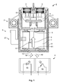
Fig. 1 . Switching arrangement 1 comprises aswitch 2 with twocontacts 3 which are arranged in acontact switching chamber 4. Aswitching device 5 serves to establish or disconnect an electric connection between the twocontacts 3. For this purpose, switchingdevice 5 is movable between separated position I represented inFig. 1 , in whichcontacts 3 are electrically separated from one another, and a bridging position, in whichcontacts 3 are connected to one another in an electrically conductive manner by switchingdevice 5. -
Switching device 5 comprises acontact bridge 18 and anarmature 6.Armature 6 is arranged in acoil 7 which is represented partially cut away inFig. 1 in order to enable a view of further elements. Depending on whether and at which strength and in which direction a current flows in the coil,armature 6, and thus switchingdevice 5, is moved in or counter to switching direction S andswitch 2 is thus electrically conductive or electrically insulating betweencontacts 3.Armature 6 represents a part of adrive 20 forcontact bridge 20. - In particular high currents or high voltages, such as are used, for example, in electric driven cars, may be present at
contacts 3.Electric contacts 3 can weld to switchingdevice 5 during use. This can lead to it no longer being possible to openswitch 2, i.e. adequate insulation can no longer be achieved. This results in a hazard, for example, when maintenance personnel are carrying out work. In order to be able to ensure thatswitch 2 is adequately insulated, switching arrangement 1 has adetector 8 which detects the position of switchingdevice 5. In particular, it detects whether switchingdevice 5 is in separated position I. For this purpose,detector 8 is aligned towards the region of arear side 61 ofarmature 6. - The detector is a
detector 8 which performsoptical measurement 8.Detector 8 is designed as a reflection light barrier.Detector 8 comprises atransmitter 81 which transmits alight beam 82.Light beam 82 is reflected in different ways in the region ofrear side 61 ofarmature 6 depending on the position ofarmature 6 and ofrear side 61 so that, depending on the position ofrear side 61, more or less light oflight beam 82 is reflected into areceiver 83.Receiver 83 converts the light into an electric signal so that downstream electronics (not represented) can evaluate whether switchingdevice 5 is in separated position I or not. -
Detector 8 can also be configured so that the presence of switchingdevice 5 in the bridging position is detected. - In the case of a sufficiently high temporal and/or spatial resolution, the movement of switching
device 5 and/or the movement ofarmature 6 can be measured over the entire armature stroke with temporal and/or spatial resolution. Such a measurement can be used, for example, to identify wear of the switching device. Such wear can be exhibited, for example, in that the stroke ofarmature 6 and/or switchingdevice 5 becomes longer and/or is displaced along switching direction S. A changed movement profile can also indicate wear. Such a changed movement profile can be identified, for example, by contrasting earlier and current location/time characteristics. In particular, for example, the position ofarmature 6 at the point in time of closing ofcontacts 3 and the end location ofarmature 6 can be measured. Wear can then be concluded from this data since this length is extended with increasing service life. - In order to enable
light beam 82 to strikerear side 61 ofarmature 6,housing 9 ofswitch 2 has a signal-permeable wall region 10 which is configured as an opening or recess in the configuration according toFig. 1 . In other configurations, a signal-permeable wall region 10 can, for example, also consist of a transparent window. In the case of such a configuration,wall region 10 allows the signals required for measurement to pass through, but enables sealing ofhousing 9, in particular a gas- and/or liquid-impervious sealing and high-voltage-impervious sealing. Signal-permeable wall region 10 is arranged on a rear side ofhousing 9.Drive 20 lies betweencontact bridge 18 andwall region 10. Moreover, the drive lies betweencontact bridge 18 anddetector 8.Drive 20 lies outsidehousing 9. Gas- and liquid-impervious sealing is not absolutely essential. Voltage-impervious, in particular high-voltage-impervious sealing is usually sufficient. Dust-impervious sealing is also advantageous. -
Wall region 10 lies in the region ofcoil 7, i.e. in the region ofdrive 20. It allows a direct sensing of an element ofdrive 20, namely ofarmature 6, without further intermediate elements. - In the case of the embodiment represented in
Fig. 1 ,detector 8 andswitch 2 are separated from one another. Both are located in each case in their own housings. In alternative configurations,detector 8 andswitch 2 can be unified in asingle housing 9. Such as housing can as a whole be gas- and/or liquid- and/or high-voltage-impervious. There can be present in such a housing 9 a high-voltage region in whichcontacts 3 are arranged and a low-voltage region in which low-voltage-operated elements, for example,detector 8, are arranged. Both regions can be separated from one another by a signal-permeable wall region 10, in particular separated from one another in a gas- and/or liquid- and/or high-voltage-impervious manner. - In one configuration, which is similar to the configuration of
Fig. 1 , the contacts can be arranged in a first housing anddetector 8 can be arranged in asecond housing 9. The housing withcontacts 3 is a high-voltage housing, the housing withdetector 8 is a low-voltage housing. The two housings can be able to be joined together so that the high-voltage housing is sealed off in a high-voltage-proof manner only in the joined-together state, for example, because open points, for example, awall region 10 can also be sealed off by the low-voltage housing. In particular, the high-voltage housing and the low-voltage housing in the joined-together state can produce an entire housing which is gas- and/or liquid- and/or high-voltage-impervious, while in the non-joined-together state at least one housing is not gas- and/or liquid- and/or voltage-impervious. - The detector is directed towards
drive 20. A direct detection of the position ofcontact bridge 18 is not necessary.Detector 8 is arranged on the side ofdrive 20 which faces away fromcontacts 3. Awall region 10 which is permeable for the signals of the measurement withdetector 8 is arranged betweendetector 8 and drive 20. This arrangement, in particular the fact thatdetector 8 is not arranged in the vicinity ofcontacts 3, in particular not incontact switching chamber 4 or inhousing 9, leads todetector 8 being protected since it is in particular not exposed to the loads or contamination during the switching process. In particular, it is not exposed to the arc plasma which occurs during opening. - A partially sectional view of a
switch 2 is represented in perspective inFig. 2 .Switching device 5 again connectscontacts 3 in an electrically conductive manner if it is located in a bridging position, not represented. For this purpose, switchingelement 5 comprises anarmature 6 and acontact bridge 18 connected thereto. The connection here is indirectly via aconnection element 11. Aspring 12 presses the contact bridge against an upper side ofconnection element 11 or, in the bridging state, againstcontacts 3.Armature 6 is arranged infriction bearings 13 which are arranged in acoil 7. Here, aspring 14 prestresses the armature in the direction of separatedposition I. Coil 7 comprises acoil body 15 andwindings 16 which are only represented schematically. - Signal-
permeable wall region 10, which is configured here as an opening inhousing 9, is particularly apparent. The position ofarmature 6 and thus of switchingdevice 5 can be detected in a contact-free manner throughwall region 10. As a result of the contact-free sensing, it is ensured that no high voltage is transmitted to the detector. - Details of a different configuration of a switching arrangement 1 are represented schematically in
Fig. 3A and 3B , in the case of which a contact-free measurement of the position ofarmature 6 is also carried out.Detector 8 used here comprises a sensor which can measure a magnetic field. This can involve, for example, a Hall sensor. Depending on the position ofarmature 6, amagnetic circuit 17 is closed or open so that the Hall sensor measures a different direction and/or intensity of magnetic field M. The position of the armature and of switchingelement 5 connected thereto can thus also be deduced. Again, the measurement is carried out in a contact-free manner. -
- 1
- Switching arrangement
- 2
- Switch
- 3
- Contact
- 4
- Contact switching chamber
- 5
- Switching device
- 6
- Armature
- 7
- Coil
- 8
- Detector, magnetic field sensor
- 9
- Housing
- 10
- Wall region
- 11
- Contact Spring
- 12
- Connection element
- 13
- Bush bearing
- 14
- Release Spring
- 15
- Coil body
- 16
- Winding
- 17
- Sensor flux guide
- 18
- Contact bridge
- 20
- Motor
- 61
- Rear side of the armature
- 81
- Light source
- 82
- Light beam
- 83
- Light sensor
- I
- Rest position
- S
- Switching direction
Claims (15)
- A switching arrangement (1), in particular for the high-voltage and/or high-current region, with two contacts (3) and a switching device (5), which can be moved into a rest position (I) in which the contacts (3) are electrically separated from one another, wherein the switching arrangement (1) comprises a detector (8) with which the presence of the switching device (5) in the separated position (I) can be detected in a contact-free manner.
- The switching arrangement (1) according to claim 1, wherein the switching device (5) comprises a motor (20) for a contact bridge (18), and the detector is directed towards the motor (20).
- The switching arrangement (1) according to any one of claims 1 or 2, wherein the switching device (5) comprises an armature (6) arranged in a coil (7) and the position of the armature (6) can be detected in a contact-free manner with the detector (8).
- The switching arrangement (1) according to any one of claims 1 to 3, wherein the presence of the switching device (5) in a bridging position, in which the contacts (3) are connected to one another by the switching device (5), can be detected in a contact-free manner with the detector (8).
- The switching arrangement (1) according to any one of claims 1 to 4, wherein the contacts (3) are arranged inside (9) and the detector (8) is arranged outside a housing (9).
- The switching arrangement (1) according to any one of claims 1 to 5, wherein the contacts (3) are arranged in a high-voltage housing and/or the detector (8) is arranged in a low-voltage housing and the high-voltage housing and/or the low-voltage housing are gas- and/or liquid-tight.
- The switching arrangement (1) according to any one of claims 1 to 6, wherein the switching arrangement (1) comprises a housing (9) which comprises a high-voltage region and a low-voltage region, wherein the contacts (3) are arranged in the high-voltage region and the detector (8) is arranged in the low-voltage region.
- The switching arrangement (1) according to any one of claims 1 to 7, wherein the detector (8), which performs measurement in a contact-free manner, is a magnetic field sensor, in particular a Hall sensor.
- The switching arrangement (1) according to any one of claims 1 to 8, wherein the detector (8), which performs measurement in a contact-free manner, is an optical sensor.
- The switching arrangement (1) according to any one of claims 1 to 9, wherein the detector (8) has a signal output at which a first signal is emitted if the switching device (5) is located in the rest position (I) and at which at least one further signal which is different from the first signal is emitted if the switching device (5) is not located in the rest position (I).
- A switch (2) for a switching arrangement (1) according to any one of claims 1 to 10, wherein a wall of a housing (9) of the switch (2) has a signal-permeable wall region (10).
- A method for measuring the switching state of a switching arrangement (1) with two contacts (3) and a switching device (5), which can be moved into a rest position (I) in which the contacts (3) are electrically separated from one another, wherein the presence of the switching device (5) in the rest position (I) is detected by a contact-free measurement of the position of the switching device (5).
- The method according to claim 12, wherein the switching device (5) comprises an armature (6) arranged in a coil (7) and the position of the armature (6) is detected in a contact-free manner.
- The method according to any one of claims 12 or 13, wherein detection is carried out through a housing wall.
- The method according to any one of claims 12 to 14, wherein wear of switching arrangement 1 and/or switching device 5 is identified by an evaluation of signals of detector 8 which performs measurement in a contact-free manner.
Applications Claiming Priority (1)
| Application Number | Priority Date | Filing Date | Title |
|---|---|---|---|
| DE102014212132.9A DE102014212132A1 (en) | 2014-06-25 | 2014-06-25 | switching arrangement |
Publications (2)
| Publication Number | Publication Date |
|---|---|
| EP2960923A1 true EP2960923A1 (en) | 2015-12-30 |
| EP2960923B1 EP2960923B1 (en) | 2023-04-12 |
Family
ID=53487291
Family Applications (1)
| Application Number | Title | Priority Date | Filing Date |
|---|---|---|---|
| EP15173735.0A Active EP2960923B1 (en) | 2014-06-25 | 2015-06-25 | Switching arrangement |
Country Status (7)
| Country | Link |
|---|---|
| US (1) | US10115512B2 (en) |
| EP (1) | EP2960923B1 (en) |
| JP (1) | JP6715576B2 (en) |
| KR (1) | KR20160000868A (en) |
| CN (1) | CN105244204B (en) |
| CA (1) | CA2895560A1 (en) |
| DE (1) | DE102014212132A1 (en) |
Cited By (4)
| Publication number | Priority date | Publication date | Assignee | Title |
|---|---|---|---|---|
| WO2019141529A1 (en) * | 2018-01-16 | 2019-07-25 | Eaton Intelligent Power Limited | Contactor with contact carrier location sensing |
| WO2020030205A1 (en) * | 2018-08-07 | 2020-02-13 | Lisa Dräxlmaier GmbH | Switching device for the controlled switching of an electrical connection and method for the controlled switching of an electrical connection |
| WO2023018583A1 (en) * | 2021-08-09 | 2023-02-16 | Webasto Charging Systems, Inc. | Relay status detection system |
| US12066304B2 (en) | 2020-09-23 | 2024-08-20 | Te Connectivity Germany Gmbh | Switching assembly and method for measuring a position of a contact bridge in a switching assembly |
Families Citing this family (22)
| Publication number | Priority date | Publication date | Assignee | Title |
|---|---|---|---|---|
| DE102015212801A1 (en) * | 2015-07-08 | 2017-01-12 | Te Connectivity Germany Gmbh | Electrical switching arrangement with improved linear storage |
| DE102016107127B4 (en) | 2016-01-29 | 2025-12-18 | Tdk Electronics Ag | relay |
| CN107204251B (en) * | 2016-03-18 | 2019-08-13 | 比亚迪股份有限公司 | Relay |
| CN107204258B (en) * | 2016-03-18 | 2019-06-25 | 比亚迪股份有限公司 | Relay |
| CN107204255B (en) * | 2016-03-18 | 2019-04-19 | 比亚迪股份有限公司 | a relay |
| CN107204253B (en) * | 2016-03-18 | 2019-04-19 | 比亚迪股份有限公司 | a relay |
| CN107204256B (en) * | 2016-03-18 | 2019-06-25 | 比亚迪股份有限公司 | relay |
| JP2018032583A (en) | 2016-08-26 | 2018-03-01 | パナソニックIpマネジメント株式会社 | Contact device, storage container used for contact device, and electromagnetic relay equipped with contact device |
| DE102017125308B4 (en) | 2017-10-27 | 2024-05-16 | Eaton Electrical Ip Gmbh & Co. Kg | Switching device with interface module |
| CN108321028A (en) * | 2018-02-24 | 2018-07-24 | 厦门赛特勒继电器有限公司 | Relay Optocoupler detection device and electromagnetic relay with the device |
| DE102018120987A1 (en) * | 2018-08-28 | 2020-03-05 | Tdk Electronics Ag | Switching device |
| KR20200000311A (en) * | 2018-08-31 | 2020-01-02 | 엘에스산전 주식회사 | Direct Current Relay |
| KR102324514B1 (en) * | 2018-08-31 | 2021-11-10 | 엘에스일렉트릭 (주) | Direct Current Relay |
| DE102018216211B3 (en) * | 2018-09-24 | 2020-02-20 | Siemens Aktiengesellschaft | Short-circuiting device and converter |
| EP3879553B1 (en) * | 2018-11-09 | 2024-01-10 | Xiamen Hongfa Electric Power Controls Co., Ltd. | Direct-current relay resistant to short-circuit current |
| CN109473314B (en) * | 2018-11-26 | 2024-02-20 | 德力西电气有限公司 | Auxiliary contact with indication function and contactor |
| DE102020122065B4 (en) | 2020-08-24 | 2022-12-01 | Te Connectivity Germany Gmbh | Contact arrangement with a measuring device for detecting a contacting state of the contact arrangement by means of an acoustic signal |
| JP2022152346A (en) * | 2021-03-29 | 2022-10-12 | いすゞ自動車株式会社 | Relay device and detection system |
| CN113517152B (en) * | 2021-05-16 | 2022-08-16 | 武汉领普科技有限公司 | Switch control method, receiving end control method, self-generating switch and receiving end |
| DE102021123868B4 (en) * | 2021-09-15 | 2025-02-20 | Te Connectivity Germany Gmbh | Electrical switching element with status indicator and kit for such a |
| CN114203481B (en) * | 2022-02-16 | 2022-04-26 | 晟望电气有限公司 | Vacuum circuit breaker on post |
| US12494333B2 (en) * | 2023-08-09 | 2025-12-09 | Sensata Technologies, Inc. | Fault breaking contactor with dynamic air gap mechanism |
Citations (5)
| Publication number | Priority date | Publication date | Assignee | Title |
|---|---|---|---|---|
| DE19941108A1 (en) * | 1999-08-30 | 2001-03-01 | Siemens Ag | Electrical safety switch with auxiliary contact coupled to opto-electrical detector to activate indicator |
| DE102004053612A1 (en) * | 2004-11-02 | 2006-05-04 | Siemens Ag | Monitoring method for a limited by relatively movable contact pieces separation distance of an electrical switching device and associated apparatus for carrying out the monitoring method |
| DE102010043352A1 (en) * | 2010-11-03 | 2012-05-03 | Tyco Electronics Amp Gmbh | Contact arrangement for a relay with two load current paths and relays with contact arrangement |
| WO2012116824A1 (en) * | 2011-03-02 | 2012-09-07 | Phoenix Contact Gmbh & Co. Kg | Electromagnetic relay having a monitored switching position |
| US20130335174A1 (en) * | 2011-03-22 | 2013-12-19 | Panasonic Corporation | Eletromagnetic opening/closing device |
Family Cites Families (29)
| Publication number | Priority date | Publication date | Assignee | Title |
|---|---|---|---|---|
| US3956649A (en) * | 1974-06-20 | 1976-05-11 | Aeroflex Laboratories, Inc. | Brushless rotary signal transducer |
| JPS59158027A (en) * | 1983-02-28 | 1984-09-07 | 株式会社東芝 | Electric switch |
| IN161314B (en) * | 1984-09-25 | 1987-11-07 | Oscar Vila Masot | |
| US4608620A (en) * | 1985-11-14 | 1986-08-26 | Westinghouse Electric Corp. | Magnetic sensor for armature and stator |
| JPH01171369U (en) * | 1988-05-23 | 1989-12-05 | ||
| JPH04206224A (en) * | 1990-11-30 | 1992-07-28 | Hitachi Ltd | electromagnetic contactor |
| US6331687B1 (en) * | 1995-05-15 | 2001-12-18 | Cooper Industries Inc. | Control method and device for a switchgear actuator |
| DE19547524C1 (en) * | 1995-12-08 | 1996-11-21 | Siemens Ag | Optical monitoring system for functional testing of HV or MV switch |
| DE29703585U1 (en) * | 1997-02-28 | 1998-06-25 | Fev Motorentech Gmbh & Co Kg | Electromagnetic actuator with magnetic impact damping |
| DE50014482D1 (en) * | 1999-06-18 | 2007-08-23 | Siemens Ag | METHOD FOR CONTROLLING AN ELECTROMECHANICAL ACTUATOR |
| DE29923323U1 (en) * | 1999-08-30 | 2000-07-06 | Siemens AG, 80333 München | Auxiliary switch |
| JP2001145253A (en) * | 1999-09-17 | 2001-05-25 | Elan Schaltelemente Gmbh & Co Kg | Electromechanical switching device |
| CN1253912C (en) * | 2003-05-29 | 2006-04-26 | 刘平 | Electric power switch apparatus |
| CN100418812C (en) * | 2003-10-28 | 2008-09-17 | 奥托利夫开发有限公司 | Buckle Switches and Buckle Mechanisms |
| KR101107809B1 (en) * | 2004-05-13 | 2012-01-25 | 미쓰비시덴키 가부시키가이샤 | State grasp device, and switching control device of power switching apparatus employing the state grasp device |
| US11404233B2 (en) * | 2004-09-13 | 2022-08-02 | Eaton Intelligent Power Limited | Fusible switching disconnect modules and devices with tripping coil |
| US11217413B2 (en) * | 2004-09-13 | 2022-01-04 | Eaton Intelligent Power Limited | Electronically controlled fusible switching disconnect modules and devices |
| US7855873B2 (en) * | 2004-09-13 | 2010-12-21 | Cooper Technologies Company | Panelboard for fusible switching disconnect devices |
| JP4648395B2 (en) * | 2004-09-13 | 2011-03-09 | クーパー テクノロジーズ カンパニー | Disconnected module and device with fuse |
| US8614618B2 (en) * | 2004-09-13 | 2013-12-24 | Cooper Technologies Company | Fusible switching disconnect modules and devices with multi-functional trip mechanism |
| US7474194B2 (en) * | 2004-09-13 | 2009-01-06 | Cooper Technologies Company | Fusible switching disconnect modules and devices |
| BRPI0519197A2 (en) * | 2004-12-23 | 2008-12-30 | Siemens Ag | process and device for the safe operation of a switchgear |
| DE102007002176B4 (en) * | 2007-01-15 | 2018-07-19 | Siemens Aktiengesellschaft | Detecting means for detecting the switching state of an electromagnetic switching device |
| DE102007030391A1 (en) * | 2007-06-29 | 2009-01-02 | Siemens Ag | Manufacturing method for a ram and such a plunger |
| JP5488103B2 (en) * | 2010-03-25 | 2014-05-14 | ヤマハ株式会社 | Displacement position detector for electromagnetic actuator |
| US20110273249A1 (en) * | 2010-05-06 | 2011-11-10 | Hubei Shengjia Electric Apparatus Co., Ltd. | Circuit breaker with secondary protection function |
| US8456259B2 (en) * | 2010-08-02 | 2013-06-04 | Martek Limited | Portable actuator |
| US8996144B2 (en) * | 2011-10-06 | 2015-03-31 | General Electric Company | Remote disconnect switch assembly |
| JP6206697B2 (en) * | 2012-11-30 | 2017-10-04 | 富士電機機器制御株式会社 | electromagnetic switch |
-
2014
- 2014-06-25 DE DE102014212132.9A patent/DE102014212132A1/en active Pending
-
2015
- 2015-06-23 CA CA2895560A patent/CA2895560A1/en not_active Abandoned
- 2015-06-24 KR KR1020150089695A patent/KR20160000868A/en not_active Abandoned
- 2015-06-24 JP JP2015126459A patent/JP6715576B2/en active Active
- 2015-06-25 EP EP15173735.0A patent/EP2960923B1/en active Active
- 2015-06-25 US US14/750,012 patent/US10115512B2/en active Active
- 2015-06-25 CN CN201510551091.2A patent/CN105244204B/en active Active
Patent Citations (5)
| Publication number | Priority date | Publication date | Assignee | Title |
|---|---|---|---|---|
| DE19941108A1 (en) * | 1999-08-30 | 2001-03-01 | Siemens Ag | Electrical safety switch with auxiliary contact coupled to opto-electrical detector to activate indicator |
| DE102004053612A1 (en) * | 2004-11-02 | 2006-05-04 | Siemens Ag | Monitoring method for a limited by relatively movable contact pieces separation distance of an electrical switching device and associated apparatus for carrying out the monitoring method |
| DE102010043352A1 (en) * | 2010-11-03 | 2012-05-03 | Tyco Electronics Amp Gmbh | Contact arrangement for a relay with two load current paths and relays with contact arrangement |
| WO2012116824A1 (en) * | 2011-03-02 | 2012-09-07 | Phoenix Contact Gmbh & Co. Kg | Electromagnetic relay having a monitored switching position |
| US20130335174A1 (en) * | 2011-03-22 | 2013-12-19 | Panasonic Corporation | Eletromagnetic opening/closing device |
Cited By (6)
| Publication number | Priority date | Publication date | Assignee | Title |
|---|---|---|---|---|
| WO2019141529A1 (en) * | 2018-01-16 | 2019-07-25 | Eaton Intelligent Power Limited | Contactor with contact carrier location sensing |
| US11948757B2 (en) | 2018-01-16 | 2024-04-02 | Eaton Intelligent Power Limited | Contactor with contact carrier location sensing |
| WO2020030205A1 (en) * | 2018-08-07 | 2020-02-13 | Lisa Dräxlmaier GmbH | Switching device for the controlled switching of an electrical connection and method for the controlled switching of an electrical connection |
| US12066304B2 (en) | 2020-09-23 | 2024-08-20 | Te Connectivity Germany Gmbh | Switching assembly and method for measuring a position of a contact bridge in a switching assembly |
| WO2023018583A1 (en) * | 2021-08-09 | 2023-02-16 | Webasto Charging Systems, Inc. | Relay status detection system |
| US11719751B2 (en) | 2021-08-09 | 2023-08-08 | Webasto Charging Systems, Inc. | Relay status detection system |
Also Published As
| Publication number | Publication date |
|---|---|
| KR20160000868A (en) | 2016-01-05 |
| CN105244204B (en) | 2020-08-14 |
| EP2960923B1 (en) | 2023-04-12 |
| CN105244204A (en) | 2016-01-13 |
| US10115512B2 (en) | 2018-10-30 |
| JP6715576B2 (en) | 2020-07-01 |
| DE102014212132A1 (en) | 2015-12-31 |
| CA2895560A1 (en) | 2015-12-25 |
| JP2016027560A (en) | 2016-02-18 |
| US20150380145A1 (en) | 2015-12-31 |
Similar Documents
| Publication | Publication Date | Title |
|---|---|---|
| EP2960923B1 (en) | Switching arrangement | |
| US10122116B2 (en) | Electrical power-point assembly with electrical disconnection solution | |
| EP2682971B1 (en) | A device for indicating the state of a switching apparatus | |
| US11170956B2 (en) | Switching arrangement | |
| US20130271120A1 (en) | Position measuring system and associated measuring method for detecting an indicated position of a linearly movable guide element | |
| US9287064B2 (en) | Switching device and method for detecting malfunctioning of such a switching device | |
| JP6400358B2 (en) | Device for detecting circuit breaker return, circuit breaker contact separation mechanism actuator, electrical circuit breaker, and use of induced current to generate return indication signal | |
| KR101560210B1 (en) | Attachment module with life monitoring for an electromagnetic switching device, and associated method | |
| US7408357B2 (en) | Device for detecting contact wear in switching appliances | |
| KR102045508B1 (en) | Earthing switch for Gas Insulated Switchgear with measurement function of ground safety | |
| EP3975214B1 (en) | Switching assembly and method for measuring a position of a contact bridge in a switching assembly | |
| JP2019532264A (en) | Monitor relative movement of two elements | |
| JP3445353B2 (en) | Operation monitoring device for power switchgear | |
| JPH09282981A (en) | Switch position detector | |
| KR102341099B1 (en) | Monitoring system for lines | |
| KR102684330B1 (en) | Monitoring device of contacting point for a vacuum circuit breaker and vacuum circuit breaker having it | |
| JP2014116184A (en) | Latching relay and watt-hour meter | |
| JPH08241653A (en) | Switch position detector | |
| JPH0956018A (en) | Power switchgear operation monitoring device | |
| CN115856608A (en) | Circuit breaker monitoring device and circuit breaker state monitoring equipment | |
| US20170077926A1 (en) | Optoelectronic safety device | |
| JP2008281371A (en) | Tester | |
| HK1250845B (en) | Electrical power-point assembly with electrical disconnection solution | |
| JP2015125120A (en) | Shock detection apparatus |
Legal Events
| Date | Code | Title | Description |
|---|---|---|---|
| PUAI | Public reference made under article 153(3) epc to a published international application that has entered the european phase |
Free format text: ORIGINAL CODE: 0009012 |
|
| AK | Designated contracting states |
Kind code of ref document: A1 Designated state(s): AL AT BE BG CH CY CZ DE DK EE ES FI FR GB GR HR HU IE IS IT LI LT LU LV MC MK MT NL NO PL PT RO RS SE SI SK SM TR |
|
| AX | Request for extension of the european patent |
Extension state: BA ME |
|
| 17P | Request for examination filed |
Effective date: 20160620 |
|
| RBV | Designated contracting states (corrected) |
Designated state(s): AL AT BE BG CH CY CZ DE DK EE ES FI FR GB GR HR HU IE IS IT LI LT LU LV MC MK MT NL NO PL PT RO RS SE SI SK SM TR |
|
| STAA | Information on the status of an ep patent application or granted ep patent |
Free format text: STATUS: EXAMINATION IS IN PROGRESS |
|
| 17Q | First examination report despatched |
Effective date: 20170522 |
|
| GRAP | Despatch of communication of intention to grant a patent |
Free format text: ORIGINAL CODE: EPIDOSNIGR1 |
|
| STAA | Information on the status of an ep patent application or granted ep patent |
Free format text: STATUS: GRANT OF PATENT IS INTENDED |
|
| INTG | Intention to grant announced |
Effective date: 20221117 |
|
| GRAS | Grant fee paid |
Free format text: ORIGINAL CODE: EPIDOSNIGR3 |
|
| GRAA | (expected) grant |
Free format text: ORIGINAL CODE: 0009210 |
|
| STAA | Information on the status of an ep patent application or granted ep patent |
Free format text: STATUS: THE PATENT HAS BEEN GRANTED |
|
| AK | Designated contracting states |
Kind code of ref document: B1 Designated state(s): AL AT BE BG CH CY CZ DE DK EE ES FI FR GB GR HR HU IE IS IT LI LT LU LV MC MK MT NL NO PL PT RO RS SE SI SK SM TR |
|
| REG | Reference to a national code |
Ref country code: GB Ref legal event code: FG4D |
|
| REG | Reference to a national code |
Ref country code: CH Ref legal event code: EP |
|
| REG | Reference to a national code |
Ref country code: DE Ref legal event code: R096 Ref document number: 602015083130 Country of ref document: DE |
|
| REG | Reference to a national code |
Ref country code: IE Ref legal event code: FG4D |
|
| REG | Reference to a national code |
Ref country code: AT Ref legal event code: REF Ref document number: 1560253 Country of ref document: AT Kind code of ref document: T Effective date: 20230515 |
|
| REG | Reference to a national code |
Ref country code: LT Ref legal event code: MG9D |
|
| REG | Reference to a national code |
Ref country code: NL Ref legal event code: MP Effective date: 20230412 |
|
| REG | Reference to a national code |
Ref country code: AT Ref legal event code: MK05 Ref document number: 1560253 Country of ref document: AT Kind code of ref document: T Effective date: 20230412 |
|
| PG25 | Lapsed in a contracting state [announced via postgrant information from national office to epo] |
Ref country code: NL Free format text: LAPSE BECAUSE OF FAILURE TO SUBMIT A TRANSLATION OF THE DESCRIPTION OR TO PAY THE FEE WITHIN THE PRESCRIBED TIME-LIMIT Effective date: 20230412 |
|
| PG25 | Lapsed in a contracting state [announced via postgrant information from national office to epo] |
Ref country code: SE Free format text: LAPSE BECAUSE OF FAILURE TO SUBMIT A TRANSLATION OF THE DESCRIPTION OR TO PAY THE FEE WITHIN THE PRESCRIBED TIME-LIMIT Effective date: 20230412 Ref country code: PT Free format text: LAPSE BECAUSE OF FAILURE TO SUBMIT A TRANSLATION OF THE DESCRIPTION OR TO PAY THE FEE WITHIN THE PRESCRIBED TIME-LIMIT Effective date: 20230814 Ref country code: NO Free format text: LAPSE BECAUSE OF FAILURE TO SUBMIT A TRANSLATION OF THE DESCRIPTION OR TO PAY THE FEE WITHIN THE PRESCRIBED TIME-LIMIT Effective date: 20230712 Ref country code: ES Free format text: LAPSE BECAUSE OF FAILURE TO SUBMIT A TRANSLATION OF THE DESCRIPTION OR TO PAY THE FEE WITHIN THE PRESCRIBED TIME-LIMIT Effective date: 20230412 Ref country code: AT Free format text: LAPSE BECAUSE OF FAILURE TO SUBMIT A TRANSLATION OF THE DESCRIPTION OR TO PAY THE FEE WITHIN THE PRESCRIBED TIME-LIMIT Effective date: 20230412 |
|
| PG25 | Lapsed in a contracting state [announced via postgrant information from national office to epo] |
Ref country code: RS Free format text: LAPSE BECAUSE OF FAILURE TO SUBMIT A TRANSLATION OF THE DESCRIPTION OR TO PAY THE FEE WITHIN THE PRESCRIBED TIME-LIMIT Effective date: 20230412 Ref country code: PL Free format text: LAPSE BECAUSE OF FAILURE TO SUBMIT A TRANSLATION OF THE DESCRIPTION OR TO PAY THE FEE WITHIN THE PRESCRIBED TIME-LIMIT Effective date: 20230412 Ref country code: LV Free format text: LAPSE BECAUSE OF FAILURE TO SUBMIT A TRANSLATION OF THE DESCRIPTION OR TO PAY THE FEE WITHIN THE PRESCRIBED TIME-LIMIT Effective date: 20230412 Ref country code: LT Free format text: LAPSE BECAUSE OF FAILURE TO SUBMIT A TRANSLATION OF THE DESCRIPTION OR TO PAY THE FEE WITHIN THE PRESCRIBED TIME-LIMIT Effective date: 20230412 Ref country code: IS Free format text: LAPSE BECAUSE OF FAILURE TO SUBMIT A TRANSLATION OF THE DESCRIPTION OR TO PAY THE FEE WITHIN THE PRESCRIBED TIME-LIMIT Effective date: 20230812 Ref country code: HR Free format text: LAPSE BECAUSE OF FAILURE TO SUBMIT A TRANSLATION OF THE DESCRIPTION OR TO PAY THE FEE WITHIN THE PRESCRIBED TIME-LIMIT Effective date: 20230412 Ref country code: GR Free format text: LAPSE BECAUSE OF FAILURE TO SUBMIT A TRANSLATION OF THE DESCRIPTION OR TO PAY THE FEE WITHIN THE PRESCRIBED TIME-LIMIT Effective date: 20230713 Ref country code: AL Free format text: LAPSE BECAUSE OF FAILURE TO SUBMIT A TRANSLATION OF THE DESCRIPTION OR TO PAY THE FEE WITHIN THE PRESCRIBED TIME-LIMIT Effective date: 20230412 |
|
| PG25 | Lapsed in a contracting state [announced via postgrant information from national office to epo] |
Ref country code: FI Free format text: LAPSE BECAUSE OF FAILURE TO SUBMIT A TRANSLATION OF THE DESCRIPTION OR TO PAY THE FEE WITHIN THE PRESCRIBED TIME-LIMIT Effective date: 20230412 |
|
| REG | Reference to a national code |
Ref country code: DE Ref legal event code: R097 Ref document number: 602015083130 Country of ref document: DE |
|
| PG25 | Lapsed in a contracting state [announced via postgrant information from national office to epo] |
Ref country code: SK Free format text: LAPSE BECAUSE OF FAILURE TO SUBMIT A TRANSLATION OF THE DESCRIPTION OR TO PAY THE FEE WITHIN THE PRESCRIBED TIME-LIMIT Effective date: 20230412 |
|
| PG25 | Lapsed in a contracting state [announced via postgrant information from national office to epo] |
Ref country code: MC Free format text: LAPSE BECAUSE OF FAILURE TO SUBMIT A TRANSLATION OF THE DESCRIPTION OR TO PAY THE FEE WITHIN THE PRESCRIBED TIME-LIMIT Effective date: 20230412 |
|
| PG25 | Lapsed in a contracting state [announced via postgrant information from national office to epo] |
Ref country code: SM Free format text: LAPSE BECAUSE OF FAILURE TO SUBMIT A TRANSLATION OF THE DESCRIPTION OR TO PAY THE FEE WITHIN THE PRESCRIBED TIME-LIMIT Effective date: 20230412 Ref country code: SK Free format text: LAPSE BECAUSE OF FAILURE TO SUBMIT A TRANSLATION OF THE DESCRIPTION OR TO PAY THE FEE WITHIN THE PRESCRIBED TIME-LIMIT Effective date: 20230412 Ref country code: RO Free format text: LAPSE BECAUSE OF FAILURE TO SUBMIT A TRANSLATION OF THE DESCRIPTION OR TO PAY THE FEE WITHIN THE PRESCRIBED TIME-LIMIT Effective date: 20230412 Ref country code: MC Free format text: LAPSE BECAUSE OF FAILURE TO SUBMIT A TRANSLATION OF THE DESCRIPTION OR TO PAY THE FEE WITHIN THE PRESCRIBED TIME-LIMIT Effective date: 20230412 Ref country code: EE Free format text: LAPSE BECAUSE OF FAILURE TO SUBMIT A TRANSLATION OF THE DESCRIPTION OR TO PAY THE FEE WITHIN THE PRESCRIBED TIME-LIMIT Effective date: 20230412 Ref country code: DK Free format text: LAPSE BECAUSE OF FAILURE TO SUBMIT A TRANSLATION OF THE DESCRIPTION OR TO PAY THE FEE WITHIN THE PRESCRIBED TIME-LIMIT Effective date: 20230412 Ref country code: CZ Free format text: LAPSE BECAUSE OF FAILURE TO SUBMIT A TRANSLATION OF THE DESCRIPTION OR TO PAY THE FEE WITHIN THE PRESCRIBED TIME-LIMIT Effective date: 20230412 |
|
| REG | Reference to a national code |
Ref country code: CH Ref legal event code: PL |
|
| PLBE | No opposition filed within time limit |
Free format text: ORIGINAL CODE: 0009261 |
|
| STAA | Information on the status of an ep patent application or granted ep patent |
Free format text: STATUS: NO OPPOSITION FILED WITHIN TIME LIMIT |
|
| REG | Reference to a national code |
Ref country code: BE Ref legal event code: MM Effective date: 20230630 |
|
| PG25 | Lapsed in a contracting state [announced via postgrant information from national office to epo] |
Ref country code: LU Free format text: LAPSE BECAUSE OF NON-PAYMENT OF DUE FEES Effective date: 20230625 |
|
| 26N | No opposition filed |
Effective date: 20240115 |
|
| GBPC | Gb: european patent ceased through non-payment of renewal fee |
Effective date: 20230712 |
|
| REG | Reference to a national code |
Ref country code: IE Ref legal event code: MM4A |
|
| PG25 | Lapsed in a contracting state [announced via postgrant information from national office to epo] |
Ref country code: LU Free format text: LAPSE BECAUSE OF NON-PAYMENT OF DUE FEES Effective date: 20230625 |
|
| PG25 | Lapsed in a contracting state [announced via postgrant information from national office to epo] |
Ref country code: IE Free format text: LAPSE BECAUSE OF NON-PAYMENT OF DUE FEES Effective date: 20230625 |
|
| PG25 | Lapsed in a contracting state [announced via postgrant information from national office to epo] |
Ref country code: IE Free format text: LAPSE BECAUSE OF NON-PAYMENT OF DUE FEES Effective date: 20230625 Ref country code: GB Free format text: LAPSE BECAUSE OF NON-PAYMENT OF DUE FEES Effective date: 20230712 Ref country code: CH Free format text: LAPSE BECAUSE OF NON-PAYMENT OF DUE FEES Effective date: 20230630 |
|
| PG25 | Lapsed in a contracting state [announced via postgrant information from national office to epo] |
Ref country code: SI Free format text: LAPSE BECAUSE OF FAILURE TO SUBMIT A TRANSLATION OF THE DESCRIPTION OR TO PAY THE FEE WITHIN THE PRESCRIBED TIME-LIMIT Effective date: 20230412 |
|
| PG25 | Lapsed in a contracting state [announced via postgrant information from national office to epo] |
Ref country code: SI Free format text: LAPSE BECAUSE OF FAILURE TO SUBMIT A TRANSLATION OF THE DESCRIPTION OR TO PAY THE FEE WITHIN THE PRESCRIBED TIME-LIMIT Effective date: 20230412 Ref country code: BE Free format text: LAPSE BECAUSE OF NON-PAYMENT OF DUE FEES Effective date: 20230630 |
|
| PG25 | Lapsed in a contracting state [announced via postgrant information from national office to epo] |
Ref country code: BG Free format text: LAPSE BECAUSE OF FAILURE TO SUBMIT A TRANSLATION OF THE DESCRIPTION OR TO PAY THE FEE WITHIN THE PRESCRIBED TIME-LIMIT Effective date: 20230412 |
|
| PG25 | Lapsed in a contracting state [announced via postgrant information from national office to epo] |
Ref country code: BG Free format text: LAPSE BECAUSE OF FAILURE TO SUBMIT A TRANSLATION OF THE DESCRIPTION OR TO PAY THE FEE WITHIN THE PRESCRIBED TIME-LIMIT Effective date: 20230412 |
|
| PGFP | Annual fee paid to national office [announced via postgrant information from national office to epo] |
Ref country code: DE Payment date: 20250402 Year of fee payment: 11 |
|
| PGFP | Annual fee paid to national office [announced via postgrant information from national office to epo] |
Ref country code: IT Payment date: 20250522 Year of fee payment: 11 |
|
| PGFP | Annual fee paid to national office [announced via postgrant information from national office to epo] |
Ref country code: FR Payment date: 20250508 Year of fee payment: 11 |
|
| PG25 | Lapsed in a contracting state [announced via postgrant information from national office to epo] |
Ref country code: CY Free format text: LAPSE BECAUSE OF FAILURE TO SUBMIT A TRANSLATION OF THE DESCRIPTION OR TO PAY THE FEE WITHIN THE PRESCRIBED TIME-LIMIT; INVALID AB INITIO Effective date: 20150625 |
|
| PG25 | Lapsed in a contracting state [announced via postgrant information from national office to epo] |
Ref country code: HU Free format text: LAPSE BECAUSE OF FAILURE TO SUBMIT A TRANSLATION OF THE DESCRIPTION OR TO PAY THE FEE WITHIN THE PRESCRIBED TIME-LIMIT; INVALID AB INITIO Effective date: 20150625 |
|
| PG25 | Lapsed in a contracting state [announced via postgrant information from national office to epo] |
Ref country code: TR Free format text: LAPSE BECAUSE OF FAILURE TO SUBMIT A TRANSLATION OF THE DESCRIPTION OR TO PAY THE FEE WITHIN THE PRESCRIBED TIME-LIMIT Effective date: 20230412 |