EP2960780A1 - Image forming apparatus and image forming method - Google Patents
Image forming apparatus and image forming method Download PDFInfo
- Publication number
- EP2960780A1 EP2960780A1 EP15173998.4A EP15173998A EP2960780A1 EP 2960780 A1 EP2960780 A1 EP 2960780A1 EP 15173998 A EP15173998 A EP 15173998A EP 2960780 A1 EP2960780 A1 EP 2960780A1
- Authority
- EP
- European Patent Office
- Prior art keywords
- paper
- dimensional object
- image
- packaging
- image forming
- Prior art date
- Legal status (The legal status is an assumption and is not a legal conclusion. Google has not performed a legal analysis and makes no representation as to the accuracy of the status listed.)
- Granted
Links
Images







Classifications
-
- G—PHYSICS
- G06—COMPUTING OR CALCULATING; COUNTING
- G06F—ELECTRIC DIGITAL DATA PROCESSING
- G06F3/00—Input arrangements for transferring data to be processed into a form capable of being handled by the computer; Output arrangements for transferring data from processing unit to output unit, e.g. interface arrangements
- G06F3/12—Digital output to print unit, e.g. line printer, chain printer
- G06F3/1201—Dedicated interfaces to print systems
- G06F3/1202—Dedicated interfaces to print systems specifically adapted to achieve a particular effect
- G06F3/1203—Improving or facilitating administration, e.g. print management
- G06F3/1208—Improving or facilitating administration, e.g. print management resulting in improved quality of the output result, e.g. print layout, colours, workflows, print preview
-
- H—ELECTRICITY
- H04—ELECTRIC COMMUNICATION TECHNIQUE
- H04N—PICTORIAL COMMUNICATION, e.g. TELEVISION
- H04N1/00—Scanning, transmission or reproduction of documents or the like, e.g. facsimile transmission; Details thereof
- H04N1/23—Reproducing arrangements
- H04N1/2307—Circuits or arrangements for the control thereof, e.g. using a programmed control device, according to a measured quantity
- H04N1/2323—Circuits or arrangements for the control thereof, e.g. using a programmed control device, according to a measured quantity according to characteristics of the reproducing medium, e.g. type, size or availability
-
- B—PERFORMING OPERATIONS; TRANSPORTING
- B41—PRINTING; LINING MACHINES; TYPEWRITERS; STAMPS
- B41F—PRINTING MACHINES OR PRESSES
- B41F33/00—Indicating, counting, warning, control or safety devices
- B41F33/16—Programming systems for automatic control of sequence of operations
-
- B—PERFORMING OPERATIONS; TRANSPORTING
- B65—CONVEYING; PACKING; STORING; HANDLING THIN OR FILAMENTARY MATERIAL
- B65B—MACHINES, APPARATUS OR DEVICES FOR, OR METHODS OF, PACKAGING ARTICLES OR MATERIALS; UNPACKING
- B65B11/00—Wrapping, e.g. partially or wholly enclosing, articles or quantities of material, in strips, sheets or blanks, of flexible material
- B65B11/004—Wrapping, e.g. partially or wholly enclosing, articles or quantities of material, in strips, sheets or blanks, of flexible material in blanks, e.g. sheets precut and creased for folding
-
- B—PERFORMING OPERATIONS; TRANSPORTING
- B65—CONVEYING; PACKING; STORING; HANDLING THIN OR FILAMENTARY MATERIAL
- B65B—MACHINES, APPARATUS OR DEVICES FOR, OR METHODS OF, PACKAGING ARTICLES OR MATERIALS; UNPACKING
- B65B61/00—Auxiliary devices, not otherwise provided for, for operating on sheets, blanks, webs, binding material, containers or packages
- B65B61/02—Auxiliary devices, not otherwise provided for, for operating on sheets, blanks, webs, binding material, containers or packages for perforating, scoring, slitting, or applying code or date marks on material prior to packaging
- B65B61/025—Auxiliary devices, not otherwise provided for, for operating on sheets, blanks, webs, binding material, containers or packages for perforating, scoring, slitting, or applying code or date marks on material prior to packaging for applying, e.g. printing, code or date marks on material prior to packaging
-
- G—PHYSICS
- G06—COMPUTING OR CALCULATING; COUNTING
- G06F—ELECTRIC DIGITAL DATA PROCESSING
- G06F3/00—Input arrangements for transferring data to be processed into a form capable of being handled by the computer; Output arrangements for transferring data from processing unit to output unit, e.g. interface arrangements
- G06F3/12—Digital output to print unit, e.g. line printer, chain printer
- G06F3/1201—Dedicated interfaces to print systems
- G06F3/1223—Dedicated interfaces to print systems specifically adapted to use a particular technique
- G06F3/1237—Print job management
- G06F3/1253—Configuration of print job parameters, e.g. using UI at the client
- G06F3/1256—User feedback, e.g. print preview, test print, proofing, pre-flight checks
-
- G—PHYSICS
- G06—COMPUTING OR CALCULATING; COUNTING
- G06F—ELECTRIC DIGITAL DATA PROCESSING
- G06F3/00—Input arrangements for transferring data to be processed into a form capable of being handled by the computer; Output arrangements for transferring data from processing unit to output unit, e.g. interface arrangements
- G06F3/12—Digital output to print unit, e.g. line printer, chain printer
- G06F3/1201—Dedicated interfaces to print systems
- G06F3/1223—Dedicated interfaces to print systems specifically adapted to use a particular technique
- G06F3/1237—Print job management
- G06F3/1253—Configuration of print job parameters, e.g. using UI at the client
- G06F3/1258—Configuration of print job parameters, e.g. using UI at the client by updating job settings at the printer
-
- G—PHYSICS
- G06—COMPUTING OR CALCULATING; COUNTING
- G06F—ELECTRIC DIGITAL DATA PROCESSING
- G06F3/00—Input arrangements for transferring data to be processed into a form capable of being handled by the computer; Output arrangements for transferring data from processing unit to output unit, e.g. interface arrangements
- G06F3/12—Digital output to print unit, e.g. line printer, chain printer
- G06F3/1201—Dedicated interfaces to print systems
- G06F3/1278—Dedicated interfaces to print systems specifically adapted to adopt a particular infrastructure
- G06F3/1285—Remote printer device, e.g. being remote from client or server
-
- H—ELECTRICITY
- H04—ELECTRIC COMMUNICATION TECHNIQUE
- H04N—PICTORIAL COMMUNICATION, e.g. TELEVISION
- H04N1/00—Scanning, transmission or reproduction of documents or the like, e.g. facsimile transmission; Details thereof
- H04N1/0035—User-machine interface; Control console
- H04N1/00405—Output means
- H04N1/00408—Display of information to the user, e.g. menus
-
- H—ELECTRICITY
- H04—ELECTRIC COMMUNICATION TECHNIQUE
- H04N—PICTORIAL COMMUNICATION, e.g. TELEVISION
- H04N1/00—Scanning, transmission or reproduction of documents or the like, e.g. facsimile transmission; Details thereof
- H04N1/23—Reproducing arrangements
- H04N1/2307—Circuits or arrangements for the control thereof, e.g. using a programmed control device, according to a measured quantity
- H04N1/2353—Selecting a particular reproducing medium from amongst a plurality of media or from a particular tray, e.g. paper or transparency
-
- B—PERFORMING OPERATIONS; TRANSPORTING
- B65—CONVEYING; PACKING; STORING; HANDLING THIN OR FILAMENTARY MATERIAL
- B65B—MACHINES, APPARATUS OR DEVICES FOR, OR METHODS OF, PACKAGING ARTICLES OR MATERIALS; UNPACKING
- B65B2210/00—Specific aspects of the packaging machine
- B65B2210/04—Customised on demand packaging by determining a specific characteristic, e.g. shape or height, of articles or material to be packaged and selecting, creating or adapting a packaging accordingly, e.g. making a carton starting from web material
-
- H—ELECTRICITY
- H04—ELECTRIC COMMUNICATION TECHNIQUE
- H04N—PICTORIAL COMMUNICATION, e.g. TELEVISION
- H04N2201/00—Indexing scheme relating to scanning, transmission or reproduction of documents or the like, and to details thereof
- H04N2201/0077—Types of the still picture apparatus
- H04N2201/0094—Multifunctional device, i.e. a device capable of all of reading, reproducing, copying, facsimile transception, file transception
Definitions
- the present disclosure relates to an image forming apparatus and an image forming method, and particularly relates to an image forming apparatus having a capability of printing a wrapping paper for packaging a three-dimensional object, and an image forming method using the same capability.
- image forming apparatuses such as printers, copying machines, and multifunctional peripherals
- image forming apparatuses have been installed not only in offices, and the like, but also in shops, such as convenience stores, where many and unspecified persons come in and out.
- services including printing out of photographs or electronic data, resident's cards, and various tickets, in addition to copying service.
- an image forming apparatus which is capable of printing a wrapping paper as one of such services.
- a development view of a wrapping paper for packaging the printed matters is printed.
- An image forming apparatus of the present disclosure is an image forming apparatus having a capability of printing a wrapping paper for packaging a three-dimensional object.
- the image forming apparatus includes an image reading part, a dimension acquisition part, a paper selection part, and an image forming part.
- the image reading part acquires an image of an object matter placed on a document table.
- the dimension acquisition part acquires dimensions of the three-dimensional object on the basis of the image of one face of the three-dimensional object, and the image of another face, crossing the one face of the three-dimensional object, the images having been acquired by the image reading part.
- the paper selection part selects a paper capable of packaging the three-dimensional object on the basis of the dimensions of the three-dimensional object, the dimensions having been acquired by the dimension acquisition part.
- the image forming part outputs a wrapping paper, having been printed with an image on the paper, the paper having been selected by the paper selection part.
- An image forming method of the present disclosure is implemented, using an image forming apparatus having a capability of printing a wrapping paper for packaging a three-dimensional object.
- an image of an object matter placed on a document table is acquired.
- an image of another face, crossing the one face of the three-dimensional dimensions of the three-dimensional object are acquired.
- a paper capable of packaging the three-dimensional object is selected.
- a wrapping paper, having been printed with an image on the selected paper is outputted.
- FIG. 1 is a schematic configuration figure showing one example of the entire configuration of the digital multifunctional peripheral in the present embodiment.
- a multifunctional peripheral 100 is provided with a main body 101 and a platen cover 102, which is mounted above the main body 101.
- the main body 101 includes an image reading part 120 and an image forming part 140.
- a document table 103 which is formed of a transparent plate, such as a contact glass.
- the document table 103 can be opened and closed by operating the platen cover 102.
- an operation panel 171 is provided on the front face of the multifunctional peripheral 100.
- the operation panel 171 is used for a user to give an instruction for starting of copying, and other instructions.
- the operation panel 171 also allows the user to confirm the conditions of the multifunctional peripheral 100 or the settings.
- an image reading part 120 is provided in the upper portion of the main body 101.
- the image reading part 120 reads an image of a document, using a scanning optical system 121.
- the image reading part 120 generates image data, which is digital data of the image.
- the image forming part 140 prints the image data on a paper. This image data is generated by the image reading part 120, or is received from another apparatus through a network (not shown).
- the image forming part 140 feeds a paper to a transfer part 155 from a manual feed tray 151, or a paper feeding cassette 152, 153, 154.
- a transfer part 155 transfers a toner image.
- the paper on which the toner image has been transferred in the transfer part 155 is delivered to a delivery tray 149.
- FIG. 2 is a hardware configuration diagram for a control system in the multifunctional peripheral.
- a CPU Central Processing Unit
- an RAM Random Access Memory
- ROM Read Only Memory
- HDD Hard Disk Drive
- the driver 205 corresponds to the respective parts of the image forming part 140.
- the ROM 203, the HDD 204, and the like, store programs.
- the CPU 201 controls the multifunctional peripheral 100 in accordance with a command of the control program. For example, the CPU 201 utilizes the RAM 202 as a working area.
- the CPU 201 controls the operation of the driver 20 by giving and receiving data or a command from/to the driver 205.
- the HDD 204 is also used for accumulation of image data. This image data is obtained by the image reading part 120, or is received from another apparatus through the network.
- an operation panel 171 and various sensors 207 are connected to the internal bus 206.
- the operation panel 171 accepts operation of the user.
- the operation panel 171 supplies a signal based on the operation to the CPU 201.
- the operation panel 171 displays an operation screen on a touch panel display provided therefor.
- the sensor 207 includes various sensors. Those various sensors are a sensor for detection of opening/closing the platen cover 102; a sensor for detection of a document on the document table; a temperature sensor for a fixing unit; a sensor for detection of a paper or document conveyed.
- the CPU 201 implements each of the following means (functional blocks) by executing a program stored in, for example, the ROM 203. In addition, the CPU 201 controls the operation of each means in response to a signal from these sensors.
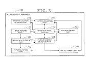
- FIG. 3 is a functional block diagram for the multifunctional peripheral of the present embodiment.
- the multifunctional peripheral 100 includes a dimension acquisition part 301, a paper selection part 302, a preview display part 303, and a packaging mode selection part 304.
- the dimension acquisition part 301 acquires dimensions of a three-dimensional object on the basis of images of two faces constituting the three-dimensional object that have been acquired by the image reading part 120.
- the reading object faces of a three-dimensional object as a packaging object on the document table 103 in turn, the images of the two faces are read by the image reading part 120.
- the two faces refer to a first face and another face (hereinafter, referred to as a second face) that crosses the first face.
- the first face is a bottom face
- the second face is any one of the side faces.
- the dimension acquisition part 301 measures the dimensions of, for example, "length” and "breadth" from the image of the first face.
- an image of the first face is referred to as a bottom face image.
- the dimension acquisition part 301 measures the dimension of "height" from the image of the second face.
- an image of the second face is referred to as a side face image.
- the three-dimensional object is preferably a rectangle parallelepiped.
- the three-dimensional object may be any three-dimensional object, for example, a truncated square pyramid, if it has an outer shape that allows packaging it practically as a rectangle parallelepiped.
- the dimension acquisition part 301 acquires the lengths of the two sides of a rectangle circumscribing the first face in the bottom face image. In addition, of the sides constituting a rectangle circumscribing the second face in the side face image, the dimension acquisition part 301 acquires the length of the side that does not constitute the circumscribing rectangle of the first face.
- the paper selection part 302 selects a paper capable of packaging the three-dimensional object on the basis of the dimensions of the three-dimensional object that have been acquired by the dimension acquisition part 301. Such dimensions are "length”, “breadth”, and “height”.
- the paper selection part 302 selects a minimum size of paper capable of packaging the three-dimensional object on the basis of the sizes of papers disposed on the manual feed tray 151 and the paper feeding cassettes 152, 153, and 154; a development view according to a later-described packaging mode; and the dimensions of the three-dimensional object.
- the paper selection part 302 selects a minimum size of paper allowing printing of a development view according to the dimensions of the three-dimensional object and the packaging mode.
- a prescribed image is printed in the image forming part 140. Then, the paper is outputted as a wrapping paper.
- folding lines a development view for packaging the three-dimensional object are printed.
- a later-described decorative pattern is printed on the other face of the paper.
- the preview display part 303 displays an appearance after packaging. This appearance after packaging is based on the dimensions of the three-dimensional object that have been acquired by the dimension acquisition part 301, and the information about the paper (the paper size) that has been selected by the paper selection part 302.
- the preview display part 303 displays the appearance after packaging on the touch panel display of the operation panel 171.
- the multifunctional peripheral 100 in the present embodiment is configured to allow a packaging mode to be selected as described later. Therefore, the packaging mode that has been selected by the user is reflected to the preview display.
- the packaging mode selection part 304 requests the user to select a packaging mode for the three-dimensional object.
- the packaging mode selection part 304 requests the user to select a packaging mode through the touch panel display of the operation panel 171.
- the packaging mode selection part 304 displays the appearances of the packaging modes on the touch panel display with selection buttons, and the like, and accepts selection by the user.
- the multifunctional peripheral 100 of the present embodiment is provided with a pattern selection part 305 and a printing location adjusting part 306.
- the pattern selection part 305 requests the user to select a decorative pattern to be printed on the paper that has been selected by the paper selection part 302.
- the pattern selection part 305 requests the user to select a packaging mode through the touch panel display of the operation panel 171.
- the pattern selection part 305 displays the appearances of the patterns on the touch panel display with selection buttons, and the like, and accepts selection by the user.
- the user can also select pattern-less printing.
- the printing location adjusting part 306 adjusts the printing location for a pattern on the paper. For example, the printing location adjusting part 306 displays an appearance including an overlapped portion of a wrapping paper on the touch panel display of the operation panel 171, and accepts adjustment of the location of the pattern in the overlapped portion, or the like, by the user.
- FIG. 4 is a flow chart giving one example of wrapping paper printing procedure that is taken with the multifunctional peripheral 100.
- the user inputs an instruction for starting the wrapping paper mode to print a wrapping paper through the operation panel 171.
- the wrapping paper printing procedure is started by, for example, inputting this starting instruction as a trigger.
- the dimension acquisition part 301 requests the user to acquire a bottom face image and a side face image (step S401).
- the dimension acquisition part 301 displays a guidance screen for acquisition of a bottom face image and a side face image on the touch panel display of the operation panel 171. This guidance screen is not particularly limited.
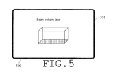
- FIG. 5 and FIG. 6 are figures each giving one example of guidance screen that is displayed on the touch panel display 500 at this time.
- a text of "Scan bottom face” and a figure showing the bottom face of a three-dimensional object are displayed on the bottom face image acquisition guidance screen 501.
- a text of "Scan side face” and a figure showing the side face of a three-dimensional object are displayed on the side face image acquisition guidance screen 601.
- the dimension acquisition part 301 When acquisition of the bottom face image and the side face image is completed, the dimension acquisition part 301 will notify the fact to the packaging mode selection part 304.
- the packaging mode selection part 304 upon having received the notification, will request the user to select a packaging mode (step S402).
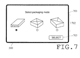
- FIG. 7 is a figure giving one example of packaging mode selection screen that the packaging mode selection part 304 displays on the touch panel display 500 at this time.
- the packaging mode selection screen 701 provides a packaging mode selection field 702 and a "Selection" button 703, which is used for confirming the selection.
- the packaging mode selection field 702 includes figures showing the appearances of "jointed wrapping", “Furoshiki wrapping", and “diagonal wrapping", and radio buttons for selecting one of these.
- FIG. 7 shows a state in which "jointed wrapping" has been selected as a default. With any one of the packaging modes having been selected, the user clicking the "Selection" button 703 will cause the selected packaging mode to be inputted to the packaging mode selection part 304.
- the packaging mode selection part 304 will notify the fact to the paper selection part 302.
- the paper selection part 302 upon having received the notification, will select a paper capable of packaging the three-dimensional object on the basis of the above-described technique (step S403). If the paper capable of packaging is not available, the paper selection part 302 will notify the user of the fact through the touch panel display of the operation panel 171, or the like.
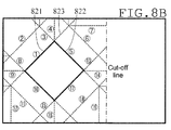
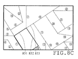
- FIG. 8A , FIG. 8B , and FIG. 8C are figures showing a development view of each of the packaging modes given as examples in FIG. 7 .
- FIG. 8A corresponds to "jointed wrapping”.
- FIG. 8B corresponds to "Furoshiki wrapping”.
- a cutoff line which indicates an unnecessary portion of the wrapping paper to be cut off, is also displayed.
- FIG. 8C corresponds to "diagonal wrapping”.
- the paper selection part 302 selects a paper by applying the "length”, “breadth”, and “height" acquired by the dimension acquisition part 301 to the development view of the packaging mode selected by the user.
- the thick lines indicate the portion where the bottom face of the three-dimensional object is to be disposed.
- the "length”, “breadth”, and “height” are, for example, sides 811, 812, and 813 (and sides opposed to these), respectively.
- the “length”, “breadth”, and “height” are, for example, sides 821, 822, and 823 (and sides opposed to these), respectively.
- the “length”, “breadth”, and “height” are, for example, sides 831, 832, and 833 (and sides opposed to these), respectively.
- the paper selection part 302 upon having selected a paper capable of packaging, will notify the fact to the packaging mode selection part 304.
- the packaging mode selection part 304 upon having received the notification, will display the information including the dimensions of the three-dimensional object that have been acquired by the dimension acquisition part 301, and the packaging mode selected by the user on the touch panel display of the operation panel 171. This is not particularly limited. Then, the user will be inquired of whether the settings are as desired (step S404).
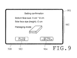
- FIG. 9 is a figure giving one example of setting confirmation screen that the packaging mode selection part 304 will display on the touch panel display 500 at this time.
- the setting confirmation screen 901 includes a setting display field 902, a "Setting change” button 903, which is used for changing the setting, and a “Setting completion” button 904, which is used for establishing the setting.
- the setting display field 902 includes the "length" and “breadth” acquired from the bottom face image, the "height" acquired from the side face image, and the packaging mode selected in the packaging mode selection screen 701.
- the packaging mode selection part 304 will notify the fact to the dimension acquisition part 301.
- the dimension acquisition part 301 will request the user to acquire a bottom face image and a side face image (S401, through No at step S404).
- the packaging mode selection part 304 will input the information including the dimensions of the three-dimensional object acquired by the dimension acquisition part 301, the information about paper (the paper size) selected by the paper selection part 302, and the packaging mode selected by the user to the preview display part 303.
- the preview display part 303 will display the appearance after packaging on the touch panel display 500 of the operation panel 171 (S405, through Yes at step S404).
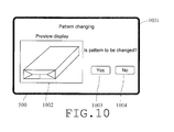
- FIG. 10 is a figure giving one example of pattern providing screen that the preview display part 303 displays on the touch panel display 500 at this time.
- the pattern providing screen 1001 includes a preview display field 1002, a "Yes" button 1003, which is used to provide a pattern, and a "No” button 1004, which is used when no pattern is to be provided.
- the preview display part 1002 an appearance after packaging that the preview display part 303 has created on the basis of the dimensions of the three-dimensional object, the paper size, and the packaging mode that have been inputted will be displayed.
- the preview display part 303 will notify the fact to the pattern selection part 305.
- the pattern selection part 305 will request the user to select a pattern that is to be printed on the paper selected by the paper selection part 302 (S407, through Yes at step S406).
- the pertinent pattern is a decorative pattern that is to be printed on the front face of the wrapping paper.
- FIG. 11 is a figure giving one example of pattern selection screen that the pattern selection part 305 will display on the touch panel display 500 at this time.
- the pattern selection screen 1101 includes a pattern selection field 1102 and a "Selection" button 1103, which is used for confirming the selection.
- the pattern selection field 1102 is comprised of figures showing a pattern in which there are disposed a plurality of characters A, which are indicated with circle marks for convenience in the figure, a pattern in which there are disposed a plurality of characters B, which are indicated with triangle marks for convenience in the figure, and a pattern in which there are disposed a plurality of characters A and characters B, and radio buttons for selecting one of these.
- FIG. 11 shows a state in which the pattern of "characters A" is selected as a default. With any one of the patterns having been selected, the user clicking the "Selection" button 1103 will cause the selected pattern to be inputted to the pattern selection part 305.
- the pattern selection part 305 will input the information about the selected pattern to the preview display part 303.
- the preview display part 303 will display the appearance of an overlapped portion for the packaging mode selected by the user with the selected pattern being provided therefor (step S408).
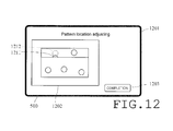
- FIG. 12 is a figure giving one example of pattern location adjusting screen that the preview display part 303 displays on the touch panel display 500 at this time.
- the pattern location adjusting screen 1201 includes a preview display field 1202 and a "Completion" button 1203, which is used for establishing the pattern.
- the preview display field 1202 the appearance that has been created by the preview display part 303 with the pattern being provided will be displayed.
- the state of the pattern in a portion where an overlap will occur in the paper after packaging will be preview-displayed.
- the state of the faces with which both ends of the paper overlap one upon another in the "jointed wrapping" is displayed.
- the pattern 1211 is hidden under the upper-layer paper.
- the user employs, for example, his own finger or a touch pen to drag the pattern 1211 on the touch panel display 500 to shift it to a location 1212 where the entire pattern is not hidden (step S409).
- the shifting operation is recognized by the printing location adjusting part 306, and is inputted to the preview display part 303 through the pattern selection part 305.
- the preview display field 1202 a preview display to which the pattern shifting operation by the user has been reflected is given.
- the decorative pattern and the folding lines are printed on different faces of the paper.
- the pattern location can be adjusted on the basis of the state after packaging, as described above. With such a configuration, the user can obtain a desired disposition of a pattern with extreme ease.
- the characters as the components of a pattern are disposed in a state in which each of them can be individually recognized.
- a particular component of a pattern rather than the entire pattern can be shifted independently of the others.
- a scheme in which, in a face with which both ends of the paper overlap one upon another, the location of a particular component of a pattern is shifted has been used as an example.
- a scheme that allows the user to optionally select a face in which a particular component of a pattern is to be shifted can be adopted.
- Pattern component shifting as described above can be performed until the user clicks the "Completion” button 1203 (in other words, the path from No at S410 to Yes at step S409 can be followed as many times as required).
- the preview display part 303 will display the appearance including the pattern after packaging on the touch panel display of the operation panel 171.
- the preview display part 303 will inquire the user of whether to execute printing or not (Yes or No at step S412).
- FIG. 13 is a figure giving one example of final confirmation screen that the preview display part 303 will display on the touch panel display 500 at this time.
- the final confirmation screen 1301 includes a preview display field 1302, a "Print” button 1303, which is used for executing printing, and a "Setting change” button 1304, which is used for changing the setting that has been inputted.
- the preview display field 1302 the dimensions of the three-dimensional object, the paper size, the packaging mode, and the appearance after packaging that have been inputted will be displayed. The appearance after packaging will be created by the preview display part 303 on the basis of the selected pattern.
- the user clicking the "Print” button 1303 will cause the preview display part 303 to notify the fact to the packaging mode selection part 304 and the pattern selection part 305 (No at step S412).
- the packaging mode selection part 304 and the pattern selection part 305 will instruct the image forming part 140 to print a wrapping paper under the conditions set. Thereby, in the image forming part 140, the wrapping paper will be printed (step S413).
- a development view shown in FIG. 8 in other words, folding lines for packaging the three-dimensional object are printed.
- the numbers that indicate the order of folding in packaging are printed, and thus the user can easily package the three-dimensional object.
- the user clicking the "Setting change” button 1304 will cause the preview display part 303 to notify the fact to the packaging mode selection part 304.
- the packaging mode selection part 304 will display the packaging mode selection screen 701 on the touch panel display 500.
- the packaging mode selection part 304 will request the user to select a packaging mode (S402, through Yes step S412). Thereby, the user can execute resetting, starting from selection of a packaging mode.
- the user clicking the "No" button 1004 will cause the preview display part 303 to notify the fact to the packaging mode selection part 304.
- the packaging mode selection part 304 will instruct the image forming part 140 to print a wrapping paper (S413, through No at step S406).
- the multifunctional peripheral 100 uses the image reading part 120 to acquire the dimensions of a three-dimensional object. Thereby, the multifunctional peripheral 100 can prepare a wrapping paper for packaging the three-dimensional object. Therefore, the user can easily obtain a desired wrapping paper by acquiring images of two faces constituting the three-dimensional object.
- the multifunctional peripheral 100 is provided with the preview display part 303. Therefore, the user can easily comprehend the state of after packaging. Further, the packaging mode selection part 304 is provided, whereby a desired packaging mode can be selected.
- the pattern selection part 305 and the printing location adjusting part 306 are provided. Therefore, in an overlapping location of the packaging paper, or the like, the location of a decorative pattern can be freely adjusted.
- the applications for wrapping papers are not limited to packaging of printed matters as contemplated by the typical art. From the viewpoint of amount of demand, it can be supposed that the amount of demand for packaging of three-dimensional objects is larger than that for packaging of printed matters.
- the application that is contemplated by the typical art is printing of wrapping papers for use with printed matters. Therefore, the typical art cannot accommodate printing of wrapping papers for use with three-dimensional objects.
- the image forming apparatus of the present disclosure can easily print wrapping papers for packaging three-dimensional objects.
- the above-described embodiment does not restrict the technical scope of the present disclosure.
- a variety of modifications or adaptations can be realized within the scope of the present disclosure.
- the preview display part 303, the packaging mode selection part 304, the pattern selection part 305, and the printing location adjusting part 306 are optional components. Even an image forming apparatus that is not provided with these components can easily print a wrapping paper for packaging a three-dimensional object in a specific packaging mode.
- folding lines for packaging a three-dimensional object are printed on one face of a wrapping paper.
- it is not essential to print all the folding lines.
- the wrapping paper is printed only with lines indicating the location where a three-dimensional object is to be disposed and a part of the folding lines, it can function as a wrapping paper.
- the flow chart shown in FIG. 4 can be altered in the order of the respective steps as appropriate, provided that an equivalent function is obtained.
- the preview display step S405 can be performed before the setting completion confirmation step S404.
- step S412 which inquires the user of whether to execute printing or not, clicking the "Setting change" button 1304 allows the user to make resetting, starting from selecting a packaging mode.
- step S406 the location where resetting is to be started may be specified to be a step, such as that for selecting providing of a pattern (step S406), rather than that for selecting a packaging mode.
- the present disclosure has been implemented as a digital multifunctional peripheral.
- the present disclosure is applicable to any image forming apparatuses, such as printers and copying machines.
- a wrapping paper for packaging a three-dimensional object can be easily printed. Therefore, the image forming apparatus of the present disclosure is extremely useful as an image forming apparatus.
Landscapes
- Engineering & Computer Science (AREA)
- Theoretical Computer Science (AREA)
- Human Computer Interaction (AREA)
- General Physics & Mathematics (AREA)
- Physics & Mathematics (AREA)
- General Engineering & Computer Science (AREA)
- Mechanical Engineering (AREA)
- Signal Processing (AREA)
- Multimedia (AREA)
- Quality & Reliability (AREA)
- Record Information Processing For Printing (AREA)
- Facsimiles In General (AREA)
- Accessory Devices And Overall Control Thereof (AREA)
Abstract
Description
- The present disclosure relates to an image forming apparatus and an image forming method, and particularly relates to an image forming apparatus having a capability of printing a wrapping paper for packaging a three-dimensional object, and an image forming method using the same capability.
- In recent years, image forming apparatuses, such as printers, copying machines, and multifunctional peripherals, have been in widespread use. Image forming apparatuses have been installed not only in offices, and the like, but also in shops, such as convenience stores, where many and unspecified persons come in and out. With such image forming apparatuses, there are provided a variety of services including printing out of photographs or electronic data, resident's cards, and various tickets, in addition to copying service.
- In the typical art, for example, an image forming apparatus has been disclosed which is capable of printing a wrapping paper as one of such services. With this art, on the basis of the number of printed matters (for example, photographs) and the size thereof, a development view of a wrapping paper for packaging the printed matters is printed.
- An image forming apparatus of the present disclosure is an image forming apparatus having a capability of printing a wrapping paper for packaging a three-dimensional object. The image forming apparatus includes an image reading part, a dimension acquisition part, a paper selection part, and an image forming part. The image reading part acquires an image of an object matter placed on a document table. The dimension acquisition part acquires dimensions of the three-dimensional object on the basis of the image of one face of the three-dimensional object, and the image of another face, crossing the one face of the three-dimensional object, the images having been acquired by the image reading part. The paper selection part selects a paper capable of packaging the three-dimensional object on the basis of the dimensions of the three-dimensional object, the dimensions having been acquired by the dimension acquisition part. The image forming part outputs a wrapping paper, having been printed with an image on the paper, the paper having been selected by the paper selection part.
- An image forming method of the present disclosure is implemented, using an image forming apparatus having a capability of printing a wrapping paper for packaging a three-dimensional object. With the present method, an image of an object matter placed on a document table is acquired. Next, on the basis of the acquired image of one face of the three-dimensional object, and the acquired image of another face, crossing the one face of the three-dimensional, dimensions of the three-dimensional object are acquired. Next, on the basis of the acquired dimensions of the three-dimensional object, a paper capable of packaging the three-dimensional object is selected. Next, a wrapping paper, having been printed with an image on the selected paper, is outputted.
-
FIG. 1 is a schematic configuration figure showing the entire configuration of a multifunctional peripheral in one embodiment of the present disclosure; -
FIG. 2 is a figure showing a hardware configuration of the multifunctional peripheral in one embodiment of the present disclosure; -
FIG. 3 is a functional block diagram illustrating a capability of the multifunctional peripheral in one embodiment of the present disclosure; -
FIG. 4 is a flow chart giving one example of wrapping paper printing procedure that is taken with the multifunctional peripheral in one embodiment of the present disclosure; -
FIG. 5 is a figure giving one example of guidance screen displayed by the multifunctional peripheral in one embodiment of the present disclosure; -
FIG. 6 is a figure giving one example of guidance screen displayed by the multifunctional peripheral in one embodiment of the present disclosure; -
FIG. 7 is a figure giving one example of packaging mode selection screen displayed by the multifunctional peripheral in one embodiment of the present disclosure; -
FIG. 8A is a figure giving one example of development view for a particular packaging mode in one embodiment of the present disclosure; -
FIG. 8B is a figure giving one example of development view for a particular packaging mode in one embodiment of the present disclosure; -
FIG. 8C is a figure giving one example of development view for a particular packaging mode in one embodiment of the present disclosure; -
FIG. 9 is a figure giving one example of setting confirmation screen displayed by the multifunctional peripheral in one embodiment of the present disclosure; -
FIG. 10 is a figure giving one example of pattern providing screen displayed by the multifunctional peripheral in one embodiment of the present disclosure; -
FIG. 11 is a figure giving one example of pattern selection screen displayed by the multifunctional peripheral in one embodiment of the present disclosure; -
FIG. 12 is a figure giving one example of pattern location adjusting screen displayed by the multifunctional peripheral in one embodiment of the present disclosure; and -
FIG. 13 is a figure giving one example of final confirmation screen displayed by the multifunctional peripheral in one embodiment of the present disclosure. - Hereinbelow, one embodiment of the present disclosure will be more specifically explained with reference to the drawings. In the following explanation, the present disclosure will be implemented as a digital multifunctional peripheral.
-
FIG. 1 is a schematic configuration figure showing one example of the entire configuration of the digital multifunctional peripheral in the present embodiment. As shown inFIG. 1 , a multifunctional peripheral 100 is provided with amain body 101 and aplaten cover 102, which is mounted above themain body 101. Themain body 101 includes animage reading part 120 and animage forming part 140. On top of themain body 101, there is provided a document table 103, which is formed of a transparent plate, such as a contact glass. The document table 103 can be opened and closed by operating theplaten cover 102. On the front face of the multifunctional peripheral 100, anoperation panel 171 is provided. Theoperation panel 171 is used for a user to give an instruction for starting of copying, and other instructions. In addition, theoperation panel 171 also allows the user to confirm the conditions of the multifunctional peripheral 100 or the settings. - In the upper portion of the
main body 101, animage reading part 120 is provided. Theimage reading part 120 reads an image of a document, using a scanningoptical system 121. Theimage reading part 120 generates image data, which is digital data of the image. - The
image forming part 140 prints the image data on a paper. This image data is generated by theimage reading part 120, or is received from another apparatus through a network (not shown). Theimage forming part 140 feeds a paper to atransfer part 155 from amanual feed tray 151, or apaper feeding cassette transfer part 155 transfers a toner image. The paper on which the toner image has been transferred in thetransfer part 155 is delivered to adelivery tray 149. -
FIG. 2 is a hardware configuration diagram for a control system in the multifunctional peripheral. In the multifunctional peripheral 100 of the present embodiment, a CPU (Central Processing Unit) 201, an RAM (Random Access Memory) 202, an ROM (Read Only Memory) 203, an HDD (Hard Disk Drive) 204, and theimage reading part 120, and adriver 205 are connected to one another through aninternal bus 206. Thedriver 205 corresponds to the respective parts of theimage forming part 140. TheROM 203, theHDD 204, and the like, store programs. TheCPU 201 controls the multifunctional peripheral 100 in accordance with a command of the control program. For example, theCPU 201 utilizes theRAM 202 as a working area. TheCPU 201 controls the operation of the driver 20 by giving and receiving data or a command from/to thedriver 205. The HDD 204 is also used for accumulation of image data. This image data is obtained by theimage reading part 120, or is received from another apparatus through the network. - To the
internal bus 206, anoperation panel 171 andvarious sensors 207 are connected. Theoperation panel 171 accepts operation of the user. Theoperation panel 171 supplies a signal based on the operation to theCPU 201. According to a control signal from theCPU 201, theoperation panel 171 displays an operation screen on a touch panel display provided therefor. Thesensor 207 includes various sensors. Those various sensors are a sensor for detection of opening/closing theplaten cover 102; a sensor for detection of a document on the document table; a temperature sensor for a fixing unit; a sensor for detection of a paper or document conveyed. - The
CPU 201 implements each of the following means (functional blocks) by executing a program stored in, for example, theROM 203. In addition, theCPU 201 controls the operation of each means in response to a signal from these sensors. -
FIG. 3 is a functional block diagram for the multifunctional peripheral of the present embodiment. As shown inFIG. 3 , the multifunctional peripheral 100 includes adimension acquisition part 301, apaper selection part 302, apreview display part 303, and a packagingmode selection part 304. - The
dimension acquisition part 301 acquires dimensions of a three-dimensional object on the basis of images of two faces constituting the three-dimensional object that have been acquired by theimage reading part 120. By disposing the reading object faces of a three-dimensional object as a packaging object on the document table 103 in turn, the images of the two faces are read by theimage reading part 120. Here, the two faces refer to a first face and another face (hereinafter, referred to as a second face) that crosses the first face. For example, when the first face is a bottom face, the second face is any one of the side faces. - The
dimension acquisition part 301 measures the dimensions of, for example, "length" and "breadth" from the image of the first face. Hereinafter, an image of the first face is referred to as a bottom face image. Thedimension acquisition part 301 measures the dimension of "height" from the image of the second face. Hereinafter, an image of the second face is referred to as a side face image. The three-dimensional object is preferably a rectangle parallelepiped. However, the three-dimensional object may be any three-dimensional object, for example, a truncated square pyramid, if it has an outer shape that allows packaging it practically as a rectangle parallelepiped. In this case, thedimension acquisition part 301 acquires the lengths of the two sides of a rectangle circumscribing the first face in the bottom face image. In addition, of the sides constituting a rectangle circumscribing the second face in the side face image, thedimension acquisition part 301 acquires the length of the side that does not constitute the circumscribing rectangle of the first face. - The
paper selection part 302 selects a paper capable of packaging the three-dimensional object on the basis of the dimensions of the three-dimensional object that have been acquired by thedimension acquisition part 301. Such dimensions are "length", "breadth", and "height". Thepaper selection part 302 selects a minimum size of paper capable of packaging the three-dimensional object on the basis of the sizes of papers disposed on themanual feed tray 151 and thepaper feeding cassettes paper selection part 302 selects a minimum size of paper allowing printing of a development view according to the dimensions of the three-dimensional object and the packaging mode. On the paper that has been selected by thepaper selection part 302, a prescribed image is printed in theimage forming part 140. Then, the paper is outputted as a wrapping paper. In the present embodiment, on one face of the paper, folding lines (a development view) for packaging the three-dimensional object are printed. In addition, on the other face of the paper, a later-described decorative pattern is printed. - The
preview display part 303 displays an appearance after packaging. This appearance after packaging is based on the dimensions of the three-dimensional object that have been acquired by thedimension acquisition part 301, and the information about the paper (the paper size) that has been selected by thepaper selection part 302. In the present embodiment, thepreview display part 303 displays the appearance after packaging on the touch panel display of theoperation panel 171. The multifunctional peripheral 100 in the present embodiment is configured to allow a packaging mode to be selected as described later. Therefore, the packaging mode that has been selected by the user is reflected to the preview display. - The packaging
mode selection part 304 requests the user to select a packaging mode for the three-dimensional object. In the present embodiment, the packagingmode selection part 304 requests the user to select a packaging mode through the touch panel display of theoperation panel 171. For example, the packagingmode selection part 304 displays the appearances of the packaging modes on the touch panel display with selection buttons, and the like, and accepts selection by the user. - In addition, the multifunctional peripheral 100 of the present embodiment is provided with a
pattern selection part 305 and a printinglocation adjusting part 306. Thepattern selection part 305 requests the user to select a decorative pattern to be printed on the paper that has been selected by thepaper selection part 302. In the present embodiment, thepattern selection part 305 requests the user to select a packaging mode through the touch panel display of theoperation panel 171. For example, thepattern selection part 305 displays the appearances of the patterns on the touch panel display with selection buttons, and the like, and accepts selection by the user. The user can also select pattern-less printing. - The printing
location adjusting part 306 adjusts the printing location for a pattern on the paper. For example, the printinglocation adjusting part 306 displays an appearance including an overlapped portion of a wrapping paper on the touch panel display of theoperation panel 171, and accepts adjustment of the location of the pattern in the overlapped portion, or the like, by the user. -
FIG. 4 is a flow chart giving one example of wrapping paper printing procedure that is taken with the multifunctional peripheral 100. For example, the user inputs an instruction for starting the wrapping paper mode to print a wrapping paper through theoperation panel 171. The wrapping paper printing procedure is started by, for example, inputting this starting instruction as a trigger. - Once the procedure is started, the
dimension acquisition part 301 requests the user to acquire a bottom face image and a side face image (step S401). In the present embodiment, at this time, thedimension acquisition part 301 displays a guidance screen for acquisition of a bottom face image and a side face image on the touch panel display of theoperation panel 171. This guidance screen is not particularly limited. -
FIG. 5 andFIG. 6 are figures each giving one example of guidance screen that is displayed on thetouch panel display 500 at this time. In this example, on the bottom face imageacquisition guidance screen 501, a text of "Scan bottom face" and a figure showing the bottom face of a three-dimensional object are displayed. Also, on the side face imageacquisition guidance screen 601, a text of "Scan side face" and a figure showing the side face of a three-dimensional object are displayed. With the bottom face imageacquisition guidance screen 501 being displayed, the user depressing the start button of theoperation panel 171 will start image acquisition by theimage reading part 120. Then, at the completion of the image acquisition, the side face imageacquisition guidance screen 601 will be displayed on thetouch panel display 500. - When acquisition of the bottom face image and the side face image is completed, the
dimension acquisition part 301 will notify the fact to the packagingmode selection part 304. The packagingmode selection part 304, upon having received the notification, will request the user to select a packaging mode (step S402). -
FIG. 7 is a figure giving one example of packaging mode selection screen that the packagingmode selection part 304 displays on thetouch panel display 500 at this time. As shown inFIG. 7 , the packagingmode selection screen 701 provides a packagingmode selection field 702 and a "Selection"button 703, which is used for confirming the selection. In this example, the packagingmode selection field 702 includes figures showing the appearances of "jointed wrapping", "Furoshiki wrapping", and "diagonal wrapping", and radio buttons for selecting one of these.FIG. 7 shows a state in which "jointed wrapping" has been selected as a default. With any one of the packaging modes having been selected, the user clicking the "Selection"button 703 will cause the selected packaging mode to be inputted to the packagingmode selection part 304. - At the completion of selection of the packaging mode, the packaging
mode selection part 304 will notify the fact to thepaper selection part 302. Thepaper selection part 302, upon having received the notification, will select a paper capable of packaging the three-dimensional object on the basis of the above-described technique (step S403). If the paper capable of packaging is not available, thepaper selection part 302 will notify the user of the fact through the touch panel display of theoperation panel 171, or the like. -
FIG. 8A ,FIG. 8B , andFIG. 8C are figures showing a development view of each of the packaging modes given as examples inFIG. 7 .FIG. 8A corresponds to "jointed wrapping".FIG. 8B corresponds to "Furoshiki wrapping". In this example, a cutoff line, which indicates an unnecessary portion of the wrapping paper to be cut off, is also displayed.FIG. 8C corresponds to "diagonal wrapping". Thepaper selection part 302 selects a paper by applying the "length", "breadth", and "height" acquired by thedimension acquisition part 301 to the development view of the packaging mode selected by the user. InFIG. 8A to FIG. 8C , the thick lines indicate the portion where the bottom face of the three-dimensional object is to be disposed. In the example given inFIG. 8A , the "length", "breadth", and "height" are, for example, sides 811, 812, and 813 (and sides opposed to these), respectively. Likewise, in the example given inFIG. 8B , the "length", "breadth", and "height" are, for example, sides 821, 822, and 823 (and sides opposed to these), respectively. Likewise, in the example given inFIG. 8C , the "length", "breadth", and "height" are, for example, sides 831, 832, and 833 (and sides opposed to these), respectively. - The
paper selection part 302, upon having selected a paper capable of packaging, will notify the fact to the packagingmode selection part 304. In the present embodiment, the packagingmode selection part 304, upon having received the notification, will display the information including the dimensions of the three-dimensional object that have been acquired by thedimension acquisition part 301, and the packaging mode selected by the user on the touch panel display of theoperation panel 171. This is not particularly limited. Then, the user will be inquired of whether the settings are as desired (step S404). -
FIG. 9 is a figure giving one example of setting confirmation screen that the packagingmode selection part 304 will display on thetouch panel display 500 at this time. As shown inFIG. 9 , thesetting confirmation screen 901 includes a settingdisplay field 902, a "Setting change"button 903, which is used for changing the setting, and a "Setting completion"button 904, which is used for establishing the setting. In this example, the settingdisplay field 902 includes the "length" and "breadth" acquired from the bottom face image, the "height" acquired from the side face image, and the packaging mode selected in the packagingmode selection screen 701. - In such state, when the user clicks the "Setting change"
button 903, the packagingmode selection part 304 will notify the fact to thedimension acquisition part 301. In response to the notification, thedimension acquisition part 301 will request the user to acquire a bottom face image and a side face image (S401, through No at step S404). - On the other hand, the user may click the "Setting completion"
button 904. In the case where the "Setting completion"button 904 is clicked, the packagingmode selection part 304 will input the information including the dimensions of the three-dimensional object acquired by thedimension acquisition part 301, the information about paper (the paper size) selected by thepaper selection part 302, and the packaging mode selected by the user to thepreview display part 303. In response to the pertinent input, thepreview display part 303 will display the appearance after packaging on thetouch panel display 500 of the operation panel 171 (S405, through Yes at step S404). -
FIG. 10 is a figure giving one example of pattern providing screen that thepreview display part 303 displays on thetouch panel display 500 at this time. As shown inFIG. 10 , thepattern providing screen 1001 includes apreview display field 1002, a "Yes"button 1003, which is used to provide a pattern, and a "No"button 1004, which is used when no pattern is to be provided. In thepreview display part 1002, an appearance after packaging that thepreview display part 303 has created on the basis of the dimensions of the three-dimensional object, the paper size, and the packaging mode that have been inputted will be displayed. - In this state, when the user clicks the Yes"
button 1003, thepreview display part 303 will notify the fact to thepattern selection part 305. In response to the notification, thepattern selection part 305 will request the user to select a pattern that is to be printed on the paper selected by the paper selection part 302 (S407, through Yes at step S406). The pertinent pattern is a decorative pattern that is to be printed on the front face of the wrapping paper. -
FIG. 11 is a figure giving one example of pattern selection screen that thepattern selection part 305 will display on thetouch panel display 500 at this time. As shown inFIG. 11 , thepattern selection screen 1101 includes apattern selection field 1102 and a "Selection"button 1103, which is used for confirming the selection. In this example, thepattern selection field 1102 is comprised of figures showing a pattern in which there are disposed a plurality of characters A, which are indicated with circle marks for convenience in the figure, a pattern in which there are disposed a plurality of characters B, which are indicated with triangle marks for convenience in the figure, and a pattern in which there are disposed a plurality of characters A and characters B, and radio buttons for selecting one of these.FIG. 11 shows a state in which the pattern of "characters A" is selected as a default. With any one of the patterns having been selected, the user clicking the "Selection"button 1103 will cause the selected pattern to be inputted to thepattern selection part 305. - At the completion of selection of the pattern, the
pattern selection part 305 will input the information about the selected pattern to thepreview display part 303. Thepreview display part 303 will display the appearance of an overlapped portion for the packaging mode selected by the user with the selected pattern being provided therefor (step S408). -
FIG. 12 is a figure giving one example of pattern location adjusting screen that thepreview display part 303 displays on thetouch panel display 500 at this time. As shown inFIG. 12 , the patternlocation adjusting screen 1201 includes apreview display field 1202 and a "Completion"button 1203, which is used for establishing the pattern. In thepreview display field 1202, the appearance that has been created by thepreview display part 303 with the pattern being provided will be displayed. In the present embodiment, in thepreview display field 1202, the state of the pattern in a portion where an overlap will occur in the paper after packaging will be preview-displayed. - In the example given in
FIG. 12 , the state of the faces with which both ends of the paper overlap one upon another in the "jointed wrapping" is displayed. In this example, the pattern 1211 is hidden under the upper-layer paper. The user employs, for example, his own finger or a touch pen to drag the pattern 1211 on thetouch panel display 500 to shift it to alocation 1212 where the entire pattern is not hidden (step S409). The shifting operation is recognized by the printinglocation adjusting part 306, and is inputted to thepreview display part 303 through thepattern selection part 305. Thereby, in thepreview display field 1202, a preview display to which the pattern shifting operation by the user has been reflected is given. In the present embodiment, the decorative pattern and the folding lines are printed on different faces of the paper. In the present embodiment, on thetouch panel display 500, the pattern location can be adjusted on the basis of the state after packaging, as described above. With such a configuration, the user can obtain a desired disposition of a pattern with extreme ease. - In the present embodiment, the characters as the components of a pattern are disposed in a state in which each of them can be individually recognized. Thereby, it is possible that a particular component of a pattern rather than the entire pattern can be shifted independently of the others. Here, a scheme in which, in a face with which both ends of the paper overlap one upon another, the location of a particular component of a pattern is shifted has been used as an example. However, a scheme that allows the user to optionally select a face in which a particular component of a pattern is to be shifted can be adopted. Further, it is also possible to adopt a scheme in which not only shifting but also addition or deletion of a component of a pattern can be performed.
- Pattern component shifting as described above can be performed until the user clicks the "Completion" button 1203 (in other words, the path from No at S410 to Yes at step S409 can be followed as many times as required). When the user clicks the "Completion"
button 1203, thepreview display part 303 will display the appearance including the pattern after packaging on the touch panel display of theoperation panel 171. In addition, thepreview display part 303 will inquire the user of whether to execute printing or not (Yes or No at step S412). -
FIG. 13 is a figure giving one example of final confirmation screen that thepreview display part 303 will display on thetouch panel display 500 at this time. As shown inFIG. 13 , thefinal confirmation screen 1301 includes apreview display field 1302, a "Print"button 1303, which is used for executing printing, and a "Setting change"button 1304, which is used for changing the setting that has been inputted. In thepreview display field 1302, the dimensions of the three-dimensional object, the paper size, the packaging mode, and the appearance after packaging that have been inputted will be displayed. The appearance after packaging will be created by thepreview display part 303 on the basis of the selected pattern. - In this state, the user clicking the "Print"
button 1303 will cause thepreview display part 303 to notify the fact to the packagingmode selection part 304 and the pattern selection part 305 (No at step S412). In response to the notification, the packagingmode selection part 304 and thepattern selection part 305 will instruct theimage forming part 140 to print a wrapping paper under the conditions set. Thereby, in theimage forming part 140, the wrapping paper will be printed (step S413). - In the present embodiment, as described above, on the face of a paper that is opposite to the face on which a decorative pattern is printed, a development view shown in
FIG. 8 , in other words, folding lines for packaging the three-dimensional object are printed. As shown inFIG. 8 , in the development view, the numbers that indicate the order of folding in packaging are printed, and thus the user can easily package the three-dimensional object. - On the other hand, with the
final confirmation screen 1301 shown inFIG. 13 being displayed, the user clicking the "Setting change"button 1304 will cause thepreview display part 303 to notify the fact to the packagingmode selection part 304. In response to the notification, the packagingmode selection part 304 will display the packagingmode selection screen 701 on thetouch panel display 500. Then, the packagingmode selection part 304 will request the user to select a packaging mode (S402, through Yes step S412). Thereby, the user can execute resetting, starting from selection of a packaging mode. - With the
preview screen 1001 shown inFIG. 10 being displayed, the user clicking the "No"button 1004 will cause thepreview display part 303 to notify the fact to the packagingmode selection part 304. In response to the notification, the packagingmode selection part 304 will instruct theimage forming part 140 to print a wrapping paper (S413, through No at step S406). - As explained above, the multifunctional peripheral 100 uses the
image reading part 120 to acquire the dimensions of a three-dimensional object. Thereby, the multifunctional peripheral 100 can prepare a wrapping paper for packaging the three-dimensional object. Therefore, the user can easily obtain a desired wrapping paper by acquiring images of two faces constituting the three-dimensional object. - In addition, the multifunctional peripheral 100 is provided with the
preview display part 303. Therefore, the user can easily comprehend the state of after packaging. Further, the packagingmode selection part 304 is provided, whereby a desired packaging mode can be selected. - In addition, the
pattern selection part 305 and the printinglocation adjusting part 306 are provided. Therefore, in an overlapping location of the packaging paper, or the like, the location of a decorative pattern can be freely adjusted. - Specifically, the applications for wrapping papers are not limited to packaging of printed matters as contemplated by the typical art. From the viewpoint of amount of demand, it can be supposed that the amount of demand for packaging of three-dimensional objects is larger than that for packaging of printed matters. However, the application that is contemplated by the typical art is printing of wrapping papers for use with printed matters. Therefore, the typical art cannot accommodate printing of wrapping papers for use with three-dimensional objects.
- Contrarily to this, the image forming apparatus of the present disclosure can easily print wrapping papers for packaging three-dimensional objects.
- The above-described embodiment does not restrict the technical scope of the present disclosure. In addition, by providing features other than those which have been already described, a variety of modifications or adaptations can be realized within the scope of the present disclosure. For example, in the above-described embodiment, a configuration in which there are provided all of the
preview display part 303, the packagingmode selection part 304, thepattern selection part 305, and the printinglocation adjusting part 306 has been explained as a particularly preferred one. However, thepreview display part 303, the packagingmode selection part 304, thepattern selection part 305, and the printinglocation adjusting part 306 are optional components. Even an image forming apparatus that is not provided with these components can easily print a wrapping paper for packaging a three-dimensional object in a specific packaging mode. In addition, in the above-described embodiment, a configuration in which folding lines for packaging a three-dimensional object are printed on one face of a wrapping paper has been supposed. However, it is not essential to print all the folding lines. For example, even if the wrapping paper is printed only with lines indicating the location where a three-dimensional object is to be disposed and a part of the folding lines, it can function as a wrapping paper. - In addition, the flow chart shown in
FIG. 4 can be altered in the order of the respective steps as appropriate, provided that an equivalent function is obtained. For example, the preview display step S405 can be performed before the setting completion confirmation step S404. In addition, in the above-described embodiment, there has been exemplified a configuration in which, in step S412, which inquires the user of whether to execute printing or not, clicking the "Setting change"button 1304 allows the user to make resetting, starting from selecting a packaging mode. However, the location where resetting is to be started may be specified to be a step, such as that for selecting providing of a pattern (step S406), rather than that for selecting a packaging mode. - In addition, in the above-described embodiment, the present disclosure has been implemented as a digital multifunctional peripheral. However, being not limited to digital multifunctional peripherals, the present disclosure is applicable to any image forming apparatuses, such as printers and copying machines.
- As an industrial applicability, according to the present disclosure, a wrapping paper for packaging a three-dimensional object can be easily printed. Therefore, the image forming apparatus of the present disclosure is extremely useful as an image forming apparatus.
Claims (7)
- An image forming apparatus having a capability of printing a wrapping paper for packaging a three-dimensional object, characterized in that:an image reading part (120), acquiring an image of an object matter placed on a document table,a dimension acquisition part (301), acquiring dimensions of the three-dimensional object on the basis of the image of one face of the three-dimensional object, and the image of another face, crossing the one face of the three-dimensional object, the images having been acquired by the image reading part (120),a paper selection part (302), selecting a paper capable of packaging the three-dimensional object on the basis of the dimensions of the three-dimensional object, the dimensions having been acquired by the dimension acquisition part (301), andan image forming part (140), outputting a wrapping paper, having been printed with an image on the paper, the paper having been selected by the paper selection part (302).
- The image forming apparatus according to claim 1, wherein the image forming part (140) prints folding lines for packaging the three-dimensional object on one face of a paper.
- The image forming apparatus according to claim 1 or 2, further comprising
a preview display part (303), displaying an appearance after packaging on the basis of the dimensions of the three-dimensional object, the dimensions having been acquired by the dimension acquisition part (301), and a piece of information about the paper, having been selected by the paper selection part (302). - The image forming apparatus according to any one of claims 1 to 3, further comprising
a packaging mode selection part (304), requesting a user to select a packaging mode for the three-dimensional object. - The image forming apparatus according to any one of claims 1 to 4, further comprising:a pattern selection part (305), requesting a user to select a pattern to be printed on the paper, anda printing location adjusting part (306), adjusting a printing location of the pattern on the paper.
- The image forming apparatus according to any one of claims 1 to 5, wherein
the three-dimensional object is a rectangle parallelepiped. - An image forming method, being implemented by an image forming apparatus having a capability of printing a wrapping paper for packaging a three-dimensional object, characterized in that the method comprising:acquiring an image of an object matter placed on a document table,acquiring dimensions of the three-dimensional object on the basis of the acquired image of one face of the three-dimensional object, and the acquired image of another face, crossing the one face of the three-dimensional,selecting a paper capable of packaging the three-dimensional object on the basis of the acquired dimensions of the three-dimensional object, andoutputting a wrapping paper, having been printed with an image on the selected paper.
Applications Claiming Priority (1)
| Application Number | Priority Date | Filing Date | Title |
|---|---|---|---|
| JP2014132454A JP6331767B2 (en) | 2014-06-27 | 2014-06-27 | Image forming apparatus |
Publications (2)
| Publication Number | Publication Date |
|---|---|
| EP2960780A1 true EP2960780A1 (en) | 2015-12-30 |
| EP2960780B1 EP2960780B1 (en) | 2020-05-20 |
Family
ID=53757959
Family Applications (1)
| Application Number | Title | Priority Date | Filing Date |
|---|---|---|---|
| EP15173998.4A Active EP2960780B1 (en) | 2014-06-27 | 2015-06-26 | Image forming apparatus and image forming method |
Country Status (4)
| Country | Link |
|---|---|
| US (1) | US20150375496A1 (en) |
| EP (1) | EP2960780B1 (en) |
| JP (1) | JP6331767B2 (en) |
| CN (1) | CN105227798B (en) |
Families Citing this family (8)
| Publication number | Priority date | Publication date | Assignee | Title |
|---|---|---|---|---|
| US10158767B2 (en) | 2015-06-09 | 2018-12-18 | Ricoh Company, Ltd. | Image capturing apparatus, image forming apparatus, distance measuring method, and computer-readable recording medium |
| US20180072448A1 (en) * | 2016-09-09 | 2018-03-15 | Fuji Xerox Co., Ltd. | Development view information generation device and wrapping sheet output apparatus |
| JP6693463B2 (en) * | 2017-04-21 | 2020-05-13 | 京セラドキュメントソリューションズ株式会社 | Image forming device |
| JP7167738B2 (en) * | 2019-01-31 | 2022-11-09 | コニカミノルタ株式会社 | PRINTING DEVICE, CONTROL METHOD AND COMPUTER PROGRAM |
| JP7242367B2 (en) * | 2019-03-22 | 2023-03-20 | キヤノン株式会社 | Packaging material data calculation device and packaging material data calculation method |
| JP7479141B2 (en) * | 2019-12-12 | 2024-05-08 | 東芝テック株式会社 | Image forming device |
| CN111498166B (en) * | 2020-03-16 | 2022-05-20 | 长沙世通纸塑箸业有限公司 | Improved chopstick packaging method |
| JP2024053340A (en) * | 2022-10-03 | 2024-04-15 | セイコーエプソン株式会社 | Image processing device, printing system, and image processing program |
Citations (1)
| Publication number | Priority date | Publication date | Assignee | Title |
|---|---|---|---|---|
| US20130067865A1 (en) * | 2011-09-16 | 2013-03-21 | Fuji Xerox Co., Ltd. | Wrapping support apparatus, computer readable medium, wrapping material, and wrapping support method |
Family Cites Families (11)
| Publication number | Priority date | Publication date | Assignee | Title |
|---|---|---|---|---|
| US4796201A (en) * | 1985-04-30 | 1989-01-03 | Wake Warren K | Stored program controlled system for creating and printing graphics bearing packaging |
| JP2002211072A (en) * | 2000-10-03 | 2002-07-31 | Yasuhiro Yoshida | Wrapping paper making device, wrapping paper making system, and wrapping paper |
| US6470232B2 (en) * | 2001-01-18 | 2002-10-22 | Hewlett-Packard Company | Customized wrapping paper kiosk |
| US20030166443A1 (en) * | 2002-02-14 | 2003-09-04 | Eastman Kodak Company | Method of producing a package wrapper |
| US7396320B2 (en) * | 2003-10-16 | 2008-07-08 | Steven Tchira | Pre-folded and pre-glued flower wrap sheets and methods for making |
| US7530210B2 (en) * | 2007-06-21 | 2009-05-12 | Xerox Corporation | Custom package wrap |
| JP2010189038A (en) * | 2009-02-18 | 2010-09-02 | Ricoh Co Ltd | Information processor, image forming device, folding information generating method, folding information generating program and recording medium |
| US8261983B2 (en) * | 2009-12-17 | 2012-09-11 | Amazon Technologies, Inc. | Generating customized packaging |
| JP2012040850A (en) * | 2010-08-23 | 2012-03-01 | Canon Inc | Printing apparatus, printing method, and program |
| JP5672048B2 (en) * | 2011-02-18 | 2015-02-18 | 富士ゼロックス株式会社 | Wrapping paper printing apparatus and program |
| JP2013241213A (en) * | 2012-05-18 | 2013-12-05 | Masachika Yaguchi | Plastic shopping bag with portions to be folded and order recorded thereon |
-
2014
- 2014-06-27 JP JP2014132454A patent/JP6331767B2/en not_active Expired - Fee Related
-
2015
- 2015-06-25 CN CN201510358728.6A patent/CN105227798B/en not_active Expired - Fee Related
- 2015-06-26 EP EP15173998.4A patent/EP2960780B1/en active Active
- 2015-06-27 US US14/752,877 patent/US20150375496A1/en not_active Abandoned
Patent Citations (1)
| Publication number | Priority date | Publication date | Assignee | Title |
|---|---|---|---|---|
| US20130067865A1 (en) * | 2011-09-16 | 2013-03-21 | Fuji Xerox Co., Ltd. | Wrapping support apparatus, computer readable medium, wrapping material, and wrapping support method |
Also Published As
| Publication number | Publication date |
|---|---|
| JP6331767B2 (en) | 2018-05-30 |
| CN105227798A (en) | 2016-01-06 |
| CN105227798B (en) | 2018-06-05 |
| JP2016010872A (en) | 2016-01-21 |
| EP2960780B1 (en) | 2020-05-20 |
| US20150375496A1 (en) | 2015-12-31 |
Similar Documents
| Publication | Publication Date | Title |
|---|---|---|
| EP2960780B1 (en) | Image forming apparatus and image forming method | |
| CA2048754C (en) | Touch screen user interface with expanding touch locations for a reprographic machine | |
| US10063722B2 (en) | Image forming apparatus configured to display function setting buttons and switch display mode between first display mode and second display mode and image recording medium | |
| US8365077B2 (en) | Help menu display processing with reference to provisional and definitive user selections | |
| NL1006469C2 (en) | Printing system for printing images on sheets in accordance with electrical image and control signals as well as control means suitable for use in such a printing system. | |
| CN104135587B (en) | Electronic equipment and print review method | |
| JP2009116789A (en) | Image forming apparatus | |
| US8542198B2 (en) | Multi-touch input actual-size display screen for scanned items | |
| US10063724B2 (en) | User interface for modifying a control's appearance to reflect a device's configuration | |
| JP3997433B2 (en) | Image forming apparatus and image forming method | |
| JP7279737B2 (en) | Information processing device, image forming device, program, and system | |
| US20110216371A1 (en) | Image processing system, image processing method, and computer readable recording medium storing program thereof | |
| JP6213418B2 (en) | Image forming apparatus | |
| US12106000B2 (en) | Printed material production system, printing method, and non-transitory computer-readable storage medium storing printed material production program | |
| JP2018063627A (en) | Image display device | |
| US20100066699A1 (en) | Image Displaying Device | |
| JP4870474B2 (en) | Parts catalog display system and control method thereof | |
| JP6551363B2 (en) | Information processing device | |
| JP2021015470A (en) | Display method and display device | |
| JP2019068442A (en) | Information processing apparatus and program | |
| JP2019149634A (en) | Image forming apparatus, display control method and program | |
| JP6772696B2 (en) | Image processing device, display device | |
| KR20070000803A (en) | Digital copier and display control method | |
| JP2017204189A (en) | Electronic device and image forming apparatus | |
| US10122877B2 (en) | Image forming apparatus |
Legal Events
| Date | Code | Title | Description |
|---|---|---|---|
| PUAI | Public reference made under article 153(3) epc to a published international application that has entered the european phase |
Free format text: ORIGINAL CODE: 0009012 |
|
| 17P | Request for examination filed |
Effective date: 20150626 |
|
| AK | Designated contracting states |
Kind code of ref document: A1 Designated state(s): AL AT BE BG CH CY CZ DE DK EE ES FI FR GB GR HR HU IE IS IT LI LT LU LV MC MK MT NL NO PL PT RO RS SE SI SK SM TR |
|
| AX | Request for extension of the european patent |
Extension state: BA ME |
|
| RBV | Designated contracting states (corrected) |
Designated state(s): AL AT BE BG CH CY CZ DE DK EE ES FI FR GB GR HR HU IE IS IT LI LT LU LV MC MK MT NL NO PL PT RO RS SE SI SK SM TR |
|
| STAA | Information on the status of an ep patent application or granted ep patent |
Free format text: STATUS: EXAMINATION IS IN PROGRESS |
|
| 17Q | First examination report despatched |
Effective date: 20181206 |
|
| GRAP | Despatch of communication of intention to grant a patent |
Free format text: ORIGINAL CODE: EPIDOSNIGR1 |
|
| STAA | Information on the status of an ep patent application or granted ep patent |
Free format text: STATUS: GRANT OF PATENT IS INTENDED |
|
| INTG | Intention to grant announced |
Effective date: 20191212 |
|
| GRAS | Grant fee paid |
Free format text: ORIGINAL CODE: EPIDOSNIGR3 |
|
| GRAA | (expected) grant |
Free format text: ORIGINAL CODE: 0009210 |
|
| STAA | Information on the status of an ep patent application or granted ep patent |
Free format text: STATUS: THE PATENT HAS BEEN GRANTED |
|
| AK | Designated contracting states |
Kind code of ref document: B1 Designated state(s): AL AT BE BG CH CY CZ DE DK EE ES FI FR GB GR HR HU IE IS IT LI LT LU LV MC MK MT NL NO PL PT RO RS SE SI SK SM TR |
|
| REG | Reference to a national code |
Ref country code: GB Ref legal event code: FG4D |
|
| REG | Reference to a national code |
Ref country code: CH Ref legal event code: EP |
|
| REG | Reference to a national code |
Ref country code: DE Ref legal event code: R096 Ref document number: 602015052980 Country of ref document: DE |
|
| REG | Reference to a national code |
Ref country code: AT Ref legal event code: REF Ref document number: 1273030 Country of ref document: AT Kind code of ref document: T Effective date: 20200615 |
|
| REG | Reference to a national code |
Ref country code: LT Ref legal event code: MG4D |
|
| REG | Reference to a national code |
Ref country code: NL Ref legal event code: MP Effective date: 20200520 |
|
| PG25 | Lapsed in a contracting state [announced via postgrant information from national office to epo] |
Ref country code: LT Free format text: LAPSE BECAUSE OF FAILURE TO SUBMIT A TRANSLATION OF THE DESCRIPTION OR TO PAY THE FEE WITHIN THE PRESCRIBED TIME-LIMIT Effective date: 20200520 Ref country code: GR Free format text: LAPSE BECAUSE OF FAILURE TO SUBMIT A TRANSLATION OF THE DESCRIPTION OR TO PAY THE FEE WITHIN THE PRESCRIBED TIME-LIMIT Effective date: 20200821 Ref country code: SE Free format text: LAPSE BECAUSE OF FAILURE TO SUBMIT A TRANSLATION OF THE DESCRIPTION OR TO PAY THE FEE WITHIN THE PRESCRIBED TIME-LIMIT Effective date: 20200520 Ref country code: NO Free format text: LAPSE BECAUSE OF FAILURE TO SUBMIT A TRANSLATION OF THE DESCRIPTION OR TO PAY THE FEE WITHIN THE PRESCRIBED TIME-LIMIT Effective date: 20200820 Ref country code: FI Free format text: LAPSE BECAUSE OF FAILURE TO SUBMIT A TRANSLATION OF THE DESCRIPTION OR TO PAY THE FEE WITHIN THE PRESCRIBED TIME-LIMIT Effective date: 20200520 Ref country code: IS Free format text: LAPSE BECAUSE OF FAILURE TO SUBMIT A TRANSLATION OF THE DESCRIPTION OR TO PAY THE FEE WITHIN THE PRESCRIBED TIME-LIMIT Effective date: 20200920 Ref country code: PT Free format text: LAPSE BECAUSE OF FAILURE TO SUBMIT A TRANSLATION OF THE DESCRIPTION OR TO PAY THE FEE WITHIN THE PRESCRIBED TIME-LIMIT Effective date: 20200921 |
|
| PG25 | Lapsed in a contracting state [announced via postgrant information from national office to epo] |
Ref country code: HR Free format text: LAPSE BECAUSE OF FAILURE TO SUBMIT A TRANSLATION OF THE DESCRIPTION OR TO PAY THE FEE WITHIN THE PRESCRIBED TIME-LIMIT Effective date: 20200520 Ref country code: RS Free format text: LAPSE BECAUSE OF FAILURE TO SUBMIT A TRANSLATION OF THE DESCRIPTION OR TO PAY THE FEE WITHIN THE PRESCRIBED TIME-LIMIT Effective date: 20200520 Ref country code: BG Free format text: LAPSE BECAUSE OF FAILURE TO SUBMIT A TRANSLATION OF THE DESCRIPTION OR TO PAY THE FEE WITHIN THE PRESCRIBED TIME-LIMIT Effective date: 20200820 Ref country code: LV Free format text: LAPSE BECAUSE OF FAILURE TO SUBMIT A TRANSLATION OF THE DESCRIPTION OR TO PAY THE FEE WITHIN THE PRESCRIBED TIME-LIMIT Effective date: 20200520 |
|
| REG | Reference to a national code |
Ref country code: AT Ref legal event code: MK05 Ref document number: 1273030 Country of ref document: AT Kind code of ref document: T Effective date: 20200520 |
|
| PG25 | Lapsed in a contracting state [announced via postgrant information from national office to epo] |
Ref country code: NL Free format text: LAPSE BECAUSE OF FAILURE TO SUBMIT A TRANSLATION OF THE DESCRIPTION OR TO PAY THE FEE WITHIN THE PRESCRIBED TIME-LIMIT Effective date: 20200520 Ref country code: AL Free format text: LAPSE BECAUSE OF FAILURE TO SUBMIT A TRANSLATION OF THE DESCRIPTION OR TO PAY THE FEE WITHIN THE PRESCRIBED TIME-LIMIT Effective date: 20200520 |
|
| PG25 | Lapsed in a contracting state [announced via postgrant information from national office to epo] |
Ref country code: IT Free format text: LAPSE BECAUSE OF FAILURE TO SUBMIT A TRANSLATION OF THE DESCRIPTION OR TO PAY THE FEE WITHIN THE PRESCRIBED TIME-LIMIT Effective date: 20200520 Ref country code: DK Free format text: LAPSE BECAUSE OF FAILURE TO SUBMIT A TRANSLATION OF THE DESCRIPTION OR TO PAY THE FEE WITHIN THE PRESCRIBED TIME-LIMIT Effective date: 20200520 Ref country code: SM Free format text: LAPSE BECAUSE OF FAILURE TO SUBMIT A TRANSLATION OF THE DESCRIPTION OR TO PAY THE FEE WITHIN THE PRESCRIBED TIME-LIMIT Effective date: 20200520 Ref country code: AT Free format text: LAPSE BECAUSE OF FAILURE TO SUBMIT A TRANSLATION OF THE DESCRIPTION OR TO PAY THE FEE WITHIN THE PRESCRIBED TIME-LIMIT Effective date: 20200520 Ref country code: EE Free format text: LAPSE BECAUSE OF FAILURE TO SUBMIT A TRANSLATION OF THE DESCRIPTION OR TO PAY THE FEE WITHIN THE PRESCRIBED TIME-LIMIT Effective date: 20200520 Ref country code: RO Free format text: LAPSE BECAUSE OF FAILURE TO SUBMIT A TRANSLATION OF THE DESCRIPTION OR TO PAY THE FEE WITHIN THE PRESCRIBED TIME-LIMIT Effective date: 20200520 Ref country code: CZ Free format text: LAPSE BECAUSE OF FAILURE TO SUBMIT A TRANSLATION OF THE DESCRIPTION OR TO PAY THE FEE WITHIN THE PRESCRIBED TIME-LIMIT Effective date: 20200520 Ref country code: ES Free format text: LAPSE BECAUSE OF FAILURE TO SUBMIT A TRANSLATION OF THE DESCRIPTION OR TO PAY THE FEE WITHIN THE PRESCRIBED TIME-LIMIT Effective date: 20200520 |
|
| REG | Reference to a national code |
Ref country code: CH Ref legal event code: PL |
|
| REG | Reference to a national code |
Ref country code: DE Ref legal event code: R097 Ref document number: 602015052980 Country of ref document: DE |
|
| PG25 | Lapsed in a contracting state [announced via postgrant information from national office to epo] |
Ref country code: MC Free format text: LAPSE BECAUSE OF FAILURE TO SUBMIT A TRANSLATION OF THE DESCRIPTION OR TO PAY THE FEE WITHIN THE PRESCRIBED TIME-LIMIT Effective date: 20200520 Ref country code: SK Free format text: LAPSE BECAUSE OF FAILURE TO SUBMIT A TRANSLATION OF THE DESCRIPTION OR TO PAY THE FEE WITHIN THE PRESCRIBED TIME-LIMIT Effective date: 20200520 Ref country code: PL Free format text: LAPSE BECAUSE OF FAILURE TO SUBMIT A TRANSLATION OF THE DESCRIPTION OR TO PAY THE FEE WITHIN THE PRESCRIBED TIME-LIMIT Effective date: 20200520 |
|
| PLBE | No opposition filed within time limit |
Free format text: ORIGINAL CODE: 0009261 |
|
| STAA | Information on the status of an ep patent application or granted ep patent |
Free format text: STATUS: NO OPPOSITION FILED WITHIN TIME LIMIT |
|
| PG25 | Lapsed in a contracting state [announced via postgrant information from national office to epo] |
Ref country code: LU Free format text: LAPSE BECAUSE OF NON-PAYMENT OF DUE FEES Effective date: 20200626 |
|
| REG | Reference to a national code |
Ref country code: BE Ref legal event code: MM Effective date: 20200630 |
|
| 26N | No opposition filed |
Effective date: 20210223 |
|
| PG25 | Lapsed in a contracting state [announced via postgrant information from national office to epo] |
Ref country code: LI Free format text: LAPSE BECAUSE OF NON-PAYMENT OF DUE FEES Effective date: 20200630 Ref country code: IE Free format text: LAPSE BECAUSE OF NON-PAYMENT OF DUE FEES Effective date: 20200626 Ref country code: CH Free format text: LAPSE BECAUSE OF NON-PAYMENT OF DUE FEES Effective date: 20200630 |
|
| PG25 | Lapsed in a contracting state [announced via postgrant information from national office to epo] |
Ref country code: BE Free format text: LAPSE BECAUSE OF NON-PAYMENT OF DUE FEES Effective date: 20200630 Ref country code: SI Free format text: LAPSE BECAUSE OF FAILURE TO SUBMIT A TRANSLATION OF THE DESCRIPTION OR TO PAY THE FEE WITHIN THE PRESCRIBED TIME-LIMIT Effective date: 20200520 |
|
| PG25 | Lapsed in a contracting state [announced via postgrant information from national office to epo] |
Ref country code: TR Free format text: LAPSE BECAUSE OF FAILURE TO SUBMIT A TRANSLATION OF THE DESCRIPTION OR TO PAY THE FEE WITHIN THE PRESCRIBED TIME-LIMIT Effective date: 20200520 Ref country code: MT Free format text: LAPSE BECAUSE OF FAILURE TO SUBMIT A TRANSLATION OF THE DESCRIPTION OR TO PAY THE FEE WITHIN THE PRESCRIBED TIME-LIMIT Effective date: 20200520 Ref country code: CY Free format text: LAPSE BECAUSE OF FAILURE TO SUBMIT A TRANSLATION OF THE DESCRIPTION OR TO PAY THE FEE WITHIN THE PRESCRIBED TIME-LIMIT Effective date: 20200520 |
|
| PG25 | Lapsed in a contracting state [announced via postgrant information from national office to epo] |
Ref country code: MK Free format text: LAPSE BECAUSE OF FAILURE TO SUBMIT A TRANSLATION OF THE DESCRIPTION OR TO PAY THE FEE WITHIN THE PRESCRIBED TIME-LIMIT Effective date: 20200520 |
|
| PGFP | Annual fee paid to national office [announced via postgrant information from national office to epo] |
Ref country code: GB Payment date: 20220506 Year of fee payment: 8 Ref country code: FR Payment date: 20220510 Year of fee payment: 8 Ref country code: DE Payment date: 20220505 Year of fee payment: 8 |
|
| P01 | Opt-out of the competence of the unified patent court (upc) registered |
Effective date: 20230420 |
|
| REG | Reference to a national code |
Ref country code: DE Ref legal event code: R119 Ref document number: 602015052980 Country of ref document: DE |
|
| GBPC | Gb: european patent ceased through non-payment of renewal fee |
Effective date: 20230626 |
|
| PG25 | Lapsed in a contracting state [announced via postgrant information from national office to epo] |
Ref country code: DE Free format text: LAPSE BECAUSE OF NON-PAYMENT OF DUE FEES Effective date: 20240103 Ref country code: GB Free format text: LAPSE BECAUSE OF NON-PAYMENT OF DUE FEES Effective date: 20230626 |
|
| PG25 | Lapsed in a contracting state [announced via postgrant information from national office to epo] |
Ref country code: FR Free format text: LAPSE BECAUSE OF NON-PAYMENT OF DUE FEES Effective date: 20230630 |