EP2960671A1 - Secondary radar - Google Patents
Secondary radar Download PDFInfo
- Publication number
- EP2960671A1 EP2960671A1 EP15172811.0A EP15172811A EP2960671A1 EP 2960671 A1 EP2960671 A1 EP 2960671A1 EP 15172811 A EP15172811 A EP 15172811A EP 2960671 A1 EP2960671 A1 EP 2960671A1
- Authority
- EP
- European Patent Office
- Prior art keywords
- signals
- difference
- antenna
- target
- elevation
- Prior art date
- Legal status (The legal status is an assumption and is not a legal conclusion. Google has not performed a legal analysis and makes no representation as to the accuracy of the status listed.)
- Granted
Links
Images


Classifications
-
- G—PHYSICS
- G01—MEASURING; TESTING
- G01S—RADIO DIRECTION-FINDING; RADIO NAVIGATION; DETERMINING DISTANCE OR VELOCITY BY USE OF RADIO WAVES; LOCATING OR PRESENCE-DETECTING BY USE OF THE REFLECTION OR RERADIATION OF RADIO WAVES; ANALOGOUS ARRANGEMENTS USING OTHER WAVES
- G01S13/00—Systems using the reflection or reradiation of radio waves, e.g. radar systems; Analogous systems using reflection or reradiation of waves whose nature or wavelength is irrelevant or unspecified
- G01S13/88—Radar or analogous systems specially adapted for specific applications
- G01S13/91—Radar or analogous systems specially adapted for specific applications for traffic control
- G01S13/913—Radar or analogous systems specially adapted for specific applications for traffic control for landing purposes
-
- G—PHYSICS
- G01—MEASURING; TESTING
- G01S—RADIO DIRECTION-FINDING; RADIO NAVIGATION; DETERMINING DISTANCE OR VELOCITY BY USE OF RADIO WAVES; LOCATING OR PRESENCE-DETECTING BY USE OF THE REFLECTION OR RERADIATION OF RADIO WAVES; ANALOGOUS ARRANGEMENTS USING OTHER WAVES
- G01S13/00—Systems using the reflection or reradiation of radio waves, e.g. radar systems; Analogous systems using reflection or reradiation of waves whose nature or wavelength is irrelevant or unspecified
- G01S13/74—Systems using reradiation of radio waves, e.g. secondary radar systems; Analogous systems
- G01S13/76—Systems using reradiation of radio waves, e.g. secondary radar systems; Analogous systems wherein pulse-type signals are transmitted
- G01S13/762—Systems using reradiation of radio waves, e.g. secondary radar systems; Analogous systems wherein pulse-type signals are transmitted with special measures concerning the radiation pattern, e.g. S.L.S.
-
- G—PHYSICS
- G01—MEASURING; TESTING
- G01S—RADIO DIRECTION-FINDING; RADIO NAVIGATION; DETERMINING DISTANCE OR VELOCITY BY USE OF RADIO WAVES; LOCATING OR PRESENCE-DETECTING BY USE OF THE REFLECTION OR RERADIATION OF RADIO WAVES; ANALOGOUS ARRANGEMENTS USING OTHER WAVES
- G01S3/00—Direction-finders for determining the direction from which infrasonic, sonic, ultrasonic, or electromagnetic waves, or particle emission, not having a directional significance, are being received
- G01S3/02—Direction-finders for determining the direction from which infrasonic, sonic, ultrasonic, or electromagnetic waves, or particle emission, not having a directional significance, are being received using radio waves
- G01S3/14—Systems for determining direction or deviation from predetermined direction
- G01S3/46—Systems for determining direction or deviation from predetermined direction using antennas spaced apart and measuring phase or time difference between signals therefrom, i.e. path-difference systems
Definitions
- the present invention relates to a secondary radar, it applies in particular to secure the air traffic approaching airports.
- the altitude is a measurement made aboard the aircraft by the altimeter from the atmospheric pressure.
- the pilot compensates the altimeter value with the standard pressure 1013.2 mbar (en route) or the pressure QNH (approaching).
- the sources of error can in fact be multiple: error on the reference pressure, error on the entry of the reference pressure, bad local barometric measurement, malfunction of the probe in particular.
- a technical problem to be solved is to secure the information transmitted by a plane in mode C from the atmospheric pressure measured by the edge altimeter.
- the additional altitude information is for example provided regardless of the interrogation protocol in synchronous mode, SSR, Mode S or IFF.
- the processing means compare, when it exists in a plot radar message, the altitude value given by said additional information transmitted by the signal received via a code C with the calculated altitude value, a potential altitude error indication being issued when said difference between the two values is greater than a given threshold when detecting a target such as a radar plot message.
- An alert is emitted for example for a given target when the occurrence of said difference is greater than the given threshold beyond a given number of consecutive antenna turns.
- Said radar comprises, for example, detection means able to exploit the difference in azimuth or elevation of the responses coming from two close targets to validate the presence of said targets.
- it comprises an additional channel CONT for the validation of the altitude information among the ADSB information considering the distance transmitted by said target.
- the figure 1 illustrates the architecture of a secondary radar according to the prior art.
- the radar comprises an antenna SSR 1, or IFF for example, constituted by parallel bars or columns located substantially in a vertical plane, each bar being itself constituted by radiating elements.
- the antenna comprises 35 columns, each column comprising 11 radiating elements.
- LVA wide vertical aperture
- Antenna 1 provides interrogation radiation at 1030 MHz and the capture of responses at 1090 MHz from transponders on board aircraft.
- the main functions of the RF unit 6 are the circulators 601, 602, 603 and conventionally the phase shifter 605 for phasing the signals received on the sum ⁇ diagrams and azimuth difference ⁇ _AZI.
- the signals from the sum channels ⁇ , CONT (sometimes ⁇ _AZI) are used by the signal processing unit 5 to detect the transponder responses present in the main lobe, then to establish for each response the misalignment of the response in the main lobe in azimuth. This is done by exploiting the signals of the sum channel ⁇ and simultaneously those coming from the difference channel ⁇ _AZI, by the function conventionally called "monopulse in azimuth".
- the responses received are assembled to constitute a pad and the azimuthal position of the target thus detected is calculated from the position of the antenna axis and the misalignment of each response (monopulse of the antenna). azimuth) used to form the plot.
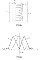
- FIGS. 2a , 2b and 2c illustrate a possible way of obtaining the sums ⁇ and difference in azimuth ⁇ _AZI according to the prior art.
- the figure 2a illustrates the formation of the lobe in elevation ⁇ '. More particularly, it represents a column 10 of radiating elements 19 and a vertical distributor 40, or microwave distribution circuit. The radiating elements 19 are connected to the distributor 40. The latter carries out the lobe in elevation ⁇ 'by amplitude and phase weighting of the signals of each radiating element 19. A signal ⁇ ' is thus produced for each column 10.
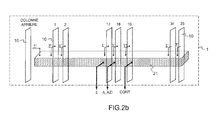
- the figure 2b illustrates the realization of the sum diagrams ⁇ , azimuth difference ⁇ _AZI and CONT control. These diagrams are conventionally made by means of a horizontal distributor 21, from the signals ⁇ 'of the amplitude and phase weighted columns and the back column for the channel CONT.
- the Figure 2c presents by two curves 28, 29 the antenna patterns as a function of the azimuth angle ⁇ .
- a first curve 28 represents the sum diagram ⁇ whose maximum corresponds to the direction of the normal 20 at the antenna at the level of the central column, this diagram ⁇ being symmetrical with respect to the normal 20.
- a second curve 29 represents the path difference ⁇ _AZI in azimuth, symmetrical relative to the normal 20 of the antenna, having a substantially zero value in the direction of normal.
- the ⁇ _AZI difference channel makes it possible to precisely locate the targets in azimuth in the main lobe of the antenna (function called azimuth monopulse).
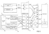
- the figure 3 illustrates a possible architecture of a radar according to the invention.
- the invention uses the vertical dimension of the secondary antenna 1, that is to say its height, to form a difference in elevation way.
- the height is sufficient to perform an elevation measurement of sufficient accuracy, using the device according to the invention, to make altitude measurements of aircraft approaching the airports to validate the altitude information, expected by the ATC controller according to the pressure correction instructions 1013.2 mbar or QNH, transmitted via the C code or any other message.
- a radar according to the invention makes a measurement of the elevation of an airplane from the same responses as those used for the detection and decoding of the C code in SSR as in S mode as in IFF. There is therefore no additional transaction to increase the reliability of the C code information, since it is the signal carrying the C code that is used to perform the elevation measurements.
- This measurement is performed on the basis of a monopulse elevation function, in a manner totally analogous to the monopulse azimuth function.
- each response received from the target the aircraft, regardless of its content (A code, C code, S mode message, IFF identification in particular), to measure the elevation of the target.
- the radar provides additional altitude information without system resource consumption or loss of performance, this altitude information being provided regardless of the synchronous mode, SSR, Mode S or IFF interrogation protocol.
- the radar architecture of the figure 3 takes over the elements of the radar architecture of the figure 1 by adding the necessary elements to the realization of the way difference in elevation.
- the conventional functions of a secondary radar, as described in relation to the figure 1 are not modified, the elevation measurement function is added in parallel with the existing functions. The elements to be added are described below.
- a new horizontal distributor 31, made on the antenna, makes it possible to form the difference diagram in elevation ⁇ _ELEV.
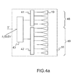
- the figure 4a has the same column 10 of radiating elements 19 as that of the figure 2a but according to the invention, the radiating elements 19 are now divided into two groups 48, 49 to form a difference in elevation ⁇ _ELEV 'channel.
- a first group 48 comprises for example four radiating elements connected to a first splitter 41 and a second group 49 comprises for example seven radiating elements connected to a second splitter 42.
- the outputs of these splitter boxes 41, 42 are themselves connected to a third distributor 43.
- These distributors 41,42, 43 make it possible to produce the same sum diagram ⁇ 'in elevation and the difference diagram in elevation ⁇ _ELEV' by weighting in amplitude and in phase of the signals of each radiating element 19.
- the figure 4b illustrates the formation of the difference diagram in elevation ⁇ _ELEV.
- the figure 4b presents the first horizontal splitter 21 already presented for the figure 2b and the new distributor 31.
- the first splitter realizes the sum diagrams ⁇ , difference in azimuth ⁇ _AZI and CONT control.
- the second splitter 31 realizes the ⁇ _ELEV diagram from the ⁇ _ELEV 'signals of the amplitude and phase weighted columns according to a law that is almost identical to that applied in the splitter 21 for the diagram ⁇ .
- the figure 5 illustrates antenna diagrams obtained by means of this additional distributor 31, by representative curves of the antenna gain.
- a first curve 51 represents the sum diagram ⁇ 'almost identical to that obtained with the device 2a and a second curve 52 represents the difference diagram in elevation ⁇ _ELEV.
- a circulator 32 makes it possible to direct the signals of the channel ⁇ _ELEV, in reception towards the treatment.
- a phase shifter 33 provides the phasing of the signals emitted on the sum channel sur and on the difference channel ⁇ _ELEV.
- the signals of the channel ⁇ _ELEV are also transposed into baseband by the reception means 4.
- the detected responses are now enriched, in addition to the azimuth misalignment, of the response in the main lobe, of the response in the main lobe in elevation by exploiting the signals of the sum channel ⁇ and simultaneously those coming from the difference channel ⁇ _ELEV, by the monopulse type function, which can be called monopulse of elevation 34 by similarity with the conventional monopulse function in azimuth.
- the responses received, assembled by the extractor 7 at the signal processing stage to constitute the stud, are now also used to constitute the elevation of the target thus measured from the misalignment in the main lobe in elevation of each response selected for constitute the plot.
- the figure 6 illustrates an aspect of the processing performed by a radar according to the invention.
- An interrogation signal 61 is transmitted via the antenna 1.
- an aircraft 62 returns, via its transponder, a response 63 of SSR type, Mode S or IFF in particular, most of the responses containing the code C conveying the barometric altitude information.
- This response is picked up by the antenna 1.
- the received signals are transmitted to the processing means as previously described.
- the processing means perform a 2D measurement of the position of the aircraft (distance and azimuth), at from, in particular, the sum diagram and the azimuthal position of the main beam of the antenna completed by the measurement resulting from the azimuth difference diagram ⁇ _AZI.
- the processing means elaborate an attribute to the response received, this attribute giving an altitude information of the aircraft by exploiting the difference in elevation diagram ⁇ _ELEV.
- the radar thus makes a measurement of the altitude of the aircraft from the same responses as those used for detection in SSR as in S or IFF mode. As indicated above, there is therefore no additional transaction to increase the reliability of the C code information, but in addition there is synchronization since it is the signal carrying the C code that is used to perform the measurements. elevation.
- the altitude information obtained by measuring the distance and the elevation ⁇ _ELEV of the target can be compared with the altitude information transmitted by the code C, decoded elsewhere, and coming from the altimeter of the plane.
- the processing means compare the difference between the altitudes at a given threshold characterizing the appearance of a potential altitude error. which can be indicated in the plot message delivered by the radar for each detected target.
- the invention therefore advantageously makes it possible, with a very small additional cost of equipment, to secure the altitude information transmitted from the aircraft.
- the low height of the secondary antenna 1 does not make it possible to obtain precise information at altitude, but this accuracy is sufficient to confirm the altitude information provided by the planes, especially when approaching the airports where the precision is then enough.
- the radar processing means verify this difference over several antenna turns.
- an alert may be transmitted to the pilot by the air traffic control, for example to order the pilot to change the altimeter or to verify the taking into account of the instruction of the pilot. controller (1013.2 mbar or QNH). Any other action that can be taken elsewhere.
- the invention also makes it possible to improve the resolution of nearby targets by also detecting the targets on the elevation difference diagram ⁇ _ELEV as is currently being done on certain SRR, Mode S or IFF radar treatments with the azimuth diagram. Indeed, two entangled responses (close distances) if they are of the same signal level are not distinguishable on the detection channel ⁇ .
- the radar integrates the asynchronous message receiving function of the radar periodically transmitted by the targets equipped with Mode S and IFF transponders (referred to in the literature as squitter) ADS-B by the current antenna diagrams ⁇ and CONT
- the difference in elevation diagram ⁇ _ELEV can be reproduced identically to that of the channel ⁇ , this time for the CONT channel, this time using the rear dipole in addition and thus making it possible to measure in a very similar manner the elevation of the squitter ADS-B in a similar way and therefore to be able to check the consistency between the barometric altitude information or GPS that it transmits with the value measured by the radar.
- the invention is applicable to the validation of the altitude information among the ADSB information considering the distance transmitted by the target.
Abstract
Le radar comporte : - une antenne secondaire (1) composée d'un ensemble de colonnes d'éléments rayonnants placées chacune dans un plan vertical, ladite antenne comportant un circuit de distribution hyperfréquence des colonnes pour former une vois somme (£) et une voie différence en azimut ; - des moyens de transmission (3, 6) et des moyens (2) de génération de signaux d'interrogation, lesdits signaux étant transmis via la dite antenne (1) vers une cible ; - des moyens de réception (4, 6) et des moyens de traitement (5) des signaux reçus via ladite antenne (1) en réponse auxdits signaux d'interrogation, lesdits moyens de traitement calculant la localisation en azimut de ladite cible à partir des signaux reçus par les voies somme et différence en azimut, une information d'altitude de ladite cible étant codée dans les signaux reçus ; - un circuit (31) de distribution hyperfréquence des lignes formées par les éléments rayonnant des différentes colonnes, lesdites lignes étant situées dans un plan horizontal afin de réaliser une voie différence en élévation, les moyens de traitement (5) calculant (4) l'altitude de ladite cible à partir des signaux reçus par ladite voie différence en élévation.The radar comprises: a secondary antenna (1) composed of a set of columns of radiating elements each placed in a vertical plane, said antenna comprising a microwave distribution circuit for the columns to form a sum sum (£) and an azimuth difference channel; - Transmission means (3, 6) and means (2) for generating interrogation signals, said signals being transmitted via said antenna (1) to a target; receiving means (4, 6) and means (5) for processing the signals received via said antenna (1) in response to said interrogation signals, said processing means calculating the azimuth location of said target from the signals received by the sum and difference channels in azimuth, an altitude information of said target being encoded in the received signals; a circuit (31) for microwave distribution of the lines formed by the radiating elements of the different columns, said lines being situated in a horizontal plane in order to produce a difference in elevation channel, the processing means (5) calculating (4) the altitude of said target from the signals received by said elevation difference channel.
Description
La présente invention concerne un radar secondaire, elle s'applique notamment pour sécuriser le trafic aérien à l'approche des aéroports.The present invention relates to a secondary radar, it applies in particular to secure the air traffic approaching airports.
L'accroissement du trafic en approche des aéroports induit un rapprochement des avions. Dans la phase d'approche d'aéroport, les avions se resserrent tout naturellement et les écarts d'altitude entre les avions diminuent. Une erreur de mesure d'altitude peut donc avoir des conséquences graves. En radar secondaire, l'altitude d'un avion est transmise au radar via le code C par le transpondeur de l'avion. C'est donc une information reçue par l'interrogateur et non une mesure classiquement effectuée par un radar primaire. Cette information peut donc être entachée d'erreur. Cependant, le mode S avec son code correcteur d'erreur en limite la probabilité d'occurrence.The increase in traffic approaching airports induces a reconciliation of aircraft. In the approach phase of the airport, planes are tightening naturally and altitude differences between aircraft are decreasing. An altitude measurement error can therefore have serious consequences. In secondary radar, the altitude of an aircraft is transmitted to the radar via code C by the transponder of the aircraft. It is therefore information received by the interrogator and not a measurement conventionally performed by a primary radar. This information can therefore be tainted by error. However, the S mode with its error correcting code limits the probability of occurrence.
Néanmoins, l'altitude est une mesure faite à bord de l'avion par l'altimètre à partir de la pression atmosphérique. Suivant la phase du vol, approche ou en route, le pilote compense la valeur de l'altimètre par la pression standard 1013.2 mbar (en route) ou la pression QNH (en approche). Il en résulte la possibilité d'erreur humaine, de la part du pilote, ou d'erreur matérielle, de la part de l'altimètre notamment. Les sources d'erreur peuvent en fait être multiples : erreur sur la pression de référence, erreur sur la saisie de la pression de référence, mauvaise mesure barométrique locale, défaut de fonctionnement de la sonde notamment.Nevertheless, the altitude is a measurement made aboard the aircraft by the altimeter from the atmospheric pressure. Following the phase of the flight, approaching or en route, the pilot compensates the altimeter value with the standard pressure 1013.2 mbar (en route) or the pressure QNH (approaching). This results in the possibility of human error, on the part of the pilot, or material error, on the part of the altimeter in particular. The sources of error can in fact be multiple: error on the reference pressure, error on the entry of the reference pressure, bad local barometric measurement, malfunction of the probe in particular.
Il est à noter qu'en fonction de la pression atmosphérique locale, une incertitude réelle allant par exemple jusqu'à +/- 400 mètres peut survenir. Ainsi, un problème technique à résoudre est de sécuriser l'information transmise par un avion en mode C à partir de la pression atmosphérique mesurée par l'altimètre de bord.It should be noted that, depending on the local atmospheric pressure, an actual uncertainty of, for example, up to +/- 400 meters can occur. Thus, a technical problem to be solved is to secure the information transmitted by a plane in mode C from the atmospheric pressure measured by the edge altimeter.
Un but de l'invention est notamment de résoudre ce problème technique, de façon fiable et économique. A cet effet, l'invention a pour objet un radar secondaire, comportant au moins :
- une antenne secondaire composée d'un ensemble de colonnes d'éléments rayonnants placées chacune dans un plan vertical, ladite antenne comportant un circuit de répartition hyperfréquence verticale, par colonne, des signaux reçus par les éléments rayonnants 19 de ladite colonne et un circuit de répartition hyperfréquence horizontale des colonnes pour former une voie somme (Σ) et une voie différence en azimut (Δ_AZI) ;
- des moyens d'émission et des moyens de génération de signaux d'interrogation, lesdits signaux étant transmis via la dite antenne vers une cible ;
- des moyens de réception et des moyens de traitement des signaux reçus via ladite antenne en réponse auxdits signaux d'interrogation, lesdits moyens de traitement calculant la localisation en azimut de ladite cible à partir des signaux reçus par les voies somme et différence en azimut, une information d'altitude de ladite cible étant codée dans les signaux reçus ;
- la répartition hyperfréquence verticale des signaux issus des éléments rayonnants par sommation pondérée en amplitude et phase pour former un signal différence en élévation (Δ_ELEV') par colonne et ;
- la répartition hyperfréquence horizontale des signaux différence en élévation (Δ_ELEV') des différentes colonnes reçus par leurs éléments rayonnants, par sommation pondérée en amplitude et phase afin de former une voie différence en élévation (Δ_ELEV) dans la direction du faisceau de ladite antenne ;
- l'implantation desdits circuits de distribution hyperfréquence sur ladite antenne, une galette RF de joint tournant transmettant les signaux de ladite voie différence en élévation vers des circuits de réception dédiés à ladite voie ;
- a secondary antenna composed of a set of columns of radiating elements each placed in a vertical plane, said antenna comprising a vertical microwave distribution circuit, by column, the signals received by the
radiating elements 19 of said column and a horizontal microwave distribution circuit of the columns to form a sum channel (Σ) and an azimuth difference channel (Δ_AZI); - transmission means and interrogation signal generating means, said signals being transmitted via said antenna to a target;
- receiving means and signal processing means received via said antenna in response to said interrogation signals, said processing means calculating the azimuth location of said target from the signals received by the sum and difference channels in azimuth, a altitude information of said target being encoded in the received signals;
- the vertical microwave distribution of the signals from the radiating elements by amplitude and phase weighted summation to form a signal difference in elevation (Δ_ELEV ') per column and;
- the horizontal hyperfrequency distribution of the signals difference in elevation (Δ_ELEV ') of the different columns received by their radiating elements, by weighted summation in amplitude and phase in order to form a difference in elevation path (Δ_ELEV) in the beam direction of said antenna;
- the implantation of said microwave distribution circuits on said antenna, a rotary joint RF wafer transmitting the signals of said difference in elevation channel to reception circuits dedicated to said channel;
L'information supplémentaire d'altitude est par exemple fournie quel que soit le protocole d'interrogation en mode synchrone, SSR, Mode S ou IFF.The additional altitude information is for example provided regardless of the interrogation protocol in synchronous mode, SSR, Mode S or IFF.
Dans un mode de réalisation possible, les moyens de traitement comparent, lorsqu'elle existe dans un message plot radar, la valeur d'altitude donnée par ladite information supplémentaire transmise par le signal reçu via un code C avec la valeur d'altitude calculée, une indication d'erreur potentielle en altitude étant émis lorsque ladite différence entre les deux valeurs est supérieure à un seuil donné lors de la détection d'une cible tel qu'un message plot radar. Une alerte est par exemple émise pour une cible donnée lorsque l'occurrence de ladite différence est supérieure au seuil donné au-delà d'un nombre donné de tours d'antennes consécutifs.In a possible embodiment, the processing means compare, when it exists in a plot radar message, the altitude value given by said additional information transmitted by the signal received via a code C with the calculated altitude value, a potential altitude error indication being issued when said difference between the two values is greater than a given threshold when detecting a target such as a radar plot message. An alert is emitted for example for a given target when the occurrence of said difference is greater than the given threshold beyond a given number of consecutive antenna turns.
Ledit radar comporte par exemple des moyens de détection aptes à exploiter la différence en azimut ou en élévation des réponses issues de deux cibles proches pour valider la présence desdites cibles.Said radar comprises, for example, detection means able to exploit the difference in azimuth or elevation of the responses coming from two close targets to validate the presence of said targets.
Avantageusement, il comporte une voie CONT supplémentaire pour la validation de l'information d'altitude parmi les informations ADSB considérant la distance transmise par ladite cible.Advantageously, it comprises an additional channel CONT for the validation of the altitude information among the ADSB information considering the distance transmitted by said target.
D'autres caractéristiques et avantages de l'invention apparaîtront à l'aide de la description qui suit, faite en regard de dessins annexés qui représentent :
- la
figure 1 , une architecture d'un radar secondaire selon l'art antérieur ; - les
figures 2a ,2b et2c , un mode d'obtention des voies somme et différence en azimut selon l'art antérieur ; - la
figure 3 , un exemple d'architecture d'un radar secondaire selon l'invention ; - les
figures 4a et4b , un exemple d'antenne secondaire avec un mode d'obtention possible des voies somme et différence en élévation ; - la
figure 5 , une illustration des diagrammes d'antenne somme et différences en élévation ; - la
figure 6 , un exemple d'exploitation d'un radar selon l'invention.
- the
figure 1 , an architecture of a secondary radar according to the prior art; - the
Figures 2a ,2b and2c , a mode for obtaining the sum and difference channels in azimuth according to the prior art; - the
figure 3 , an exemplary architecture of a secondary radar according to the invention; - the
Figures 4a and4b , an example of a secondary antenna with a possible way of obtaining the sum and difference in elevation channels; - the
figure 5 , an illustration of antenna patterns sum and differences in elevation; - the
figure 6 , an example of exploitation of a radar according to the invention.
La
L'antenne 1 assure le rayonnement des interrogations, à 1030 MHz, et la captation des réponses, à 1090 MHz, issues des transpondeurs à bord des aéronefs.
Les autres unités composant le radar sont notamment les suivantes :
- une
unité 2 de gestion spatio-temporelle, générant les interrogations secondaire mode S en fonction des tâches à effectuer avec les cibles prédites présentes dans le lobe principal, cette entité élabore notamment les interrogations SSR, MS et IFF ainsi que les interrogations ISLS ; - un
émetteur 3, convertissant en signaux RF de forte puissance les interrogations à rayonner par l'antenne 1 ; - un récepteur 4, démodulant les signaux RF reçus par l'antenne 1 ;
- une
unité 5 de traitement des signaux et des données, détectant et décodant les réponses reçues dans le lobe principal de l'antenne ; - une
unité RF 6 assurant le transfert des signaux RF depuis et vers les diagrammes d'antenne, à cet effet elle comporte classiquement descirculateurs hyperfréquence
- a spatio-
temporal management unit 2, generating the secondary mode S interrogations as a function of the tasks to be performed with the predicted targets present in the main lobe, this entity notably elaborates the SSR, MS and IFF interrogations as well as the ISLS interrogations; - a
transmitter 3, converting into high power RF signals the interrogations to be radiated by theantenna 1; - a receiver 4, demodulating the RF signals received by the
antenna 1; - a signal and
data processing unit 5, detecting and decoding the received responses in the main lobe of the antenna; - an
RF unit 6 transferring the RF signals to and from the antenna patterns, for this purpose it conventionally comprisesmicrowave circulators
Dans les radars actuels, classiquement les diagrammes utilisés sont :
- En émission, les diagrammes somme Σ et contrôle CONT, pour l'interrogation des avions dans le lobe principal de l'antenne ;
- En réception, les diagrammes somme Σ et contrôle CONT pour la détection des réponses dans le lobe principal et la voie différence en azimut Δ_AZI pour la localisation fine de la cible dans le lobe principal de l'antenne. La voie Δ_AZI peut aussi être utilisée pour la détection en cas de réponses emmêlées.
- In emission, the sum charts Σ and CONT control, for the interrogation of the planes in the main lobe of the antenna;
- In reception, the sum Σ diagrams and CONT control for detecting responses in the main lobe and the difference channel in Δ_AZI azimuth for the fine localization of the target in the main lobe of the antenna. The Δ_AZI channel can also be used for detection in case of entangled responses.
Les principales fonctions de l'unité RF 6 sont les circulateurs 601, 602, 603 et classiquement le déphaseur 605 permettant la mise en phase des signaux reçus sur les diagrammes somme Σ et différence en azimut Δ_AZI.The main functions of the
Une fois transposés en bande de base par le récepteur 4, les signaux issus des voies somme Σ, CONT (quelquefois Δ_AZI) sont exploités par l'unité 5 de traitement du signal pour détecter les réponses des transpondeurs présents dans le lobe principal, puis pour établir pour chaque réponse le dépointage de la réponse dans le lobe principal en azimut. Ceci est réalisé en exploitant les signaux de la voie somme Σ et simultanément ceux issus de la voie différence Δ_AZI, par la fonction dénommée classiquement « monopulse en azimut ».Once transposed in baseband by the receiver 4, the signals from the sum channels Σ, CONT (sometimes Δ_AZI) are used by the
Au niveau du traitement des données 5, les réponses reçues sont assemblées pour constituer un plot et la position azimutale de la cible ainsi détectée est calculée à partir de la position de l'axe de l'antenne et du dépointage de chaque réponse (monopulse d'azimut) retenue pour constituer le plot.At the
Les
La
La
La
La
Plus précisément, avantageusement, un radar selon l'invention effectue une mesure de l'élévation d'un avion à partir des mêmes réponses que celles utilisées pour la détection et le décodage du code C en SSR comme en mode S comme en IFF. Il n'y a donc pas de transaction supplémentaire pour accroître la fiabilité de l'information de code C, puisque c'est le signal véhiculant ce code C qui est exploité pour effectuer les mesures d'élévation. Cette mesure est effectuée sur la base d'une fonction monopulse d'élévation, de manière totalement analogue à la fonction monopulse d'azimut. Ainsi, chaque réponse reçue de la cible, l'avion, quel que soit son contenu (code A, code C, message mode S, identification IFF notamment), permet de mesurer l'élévation de la cible. Le radar fournit une information supplémentaire d'altitude sans consommation de ressources système ni perte de performance, cette information d'altitude étant fournie quel que soit le protocole d'interrogation en mode synchrone, SSR, Mode S ou IFF. L'architecture radar de la
Un nouveau répartiteur horizontal 31, réalisé sur l'antenne, permet de former le diagramme différence en élévation Δ_ELEV.A new
Les
La
La
La
On revient à la
Un circulateur 32 permet d'aiguiller les signaux de la voie Δ_ELEV, en réception vers le traitement.A
Un déphaseur 33 assure la mise en phase des signaux émis sur la voie somme Σ et sur la voie différence Δ_ELEV. Les signaux de la voie Δ_ELEV sont aussi transposés en bande de base par les moyens de réception 4.A
Au niveau du traitement du signal 5, les réponses détectées sont désormais enrichies, en plus du dépointage en azimut, de la réponse dans le lobe principal, de la réponse dans le lobe principal en élévation en exploitant les signaux de la voie somme Σ et simultanément ceux issus de la voie différence Δ_ELEV, par la fonction de type monopulse, que l'on peut nommer monopulse d'élévation 34 par similitude avec la fonction classique de monopulse en azimut.At the
Les réponses reçues, assemblées par l'extracteur 7 au niveau du traitement du signal pour constituer le plot, servent désormais aussi pour constituer 35 l'élévation de la cible ainsi mesurée à partir du dépointage dans le lobe principal en élévation de chaque réponse retenue pour constituer le plot.The responses received, assembled by the
La
Le radar effectue ainsi une mesure de l'altitude de l'avion à partir des mêmes réponses que celles utilisées pour la détection en SSR comme en mode S ou IFF. Comme indiqué précédemment, il n'y a donc pas de transaction supplémentaire pour accroître la fiabilité de l'information de code C, mais en plus il y a synchronisation puisque c'est le signal véhiculant ce code C qui est exploité pour effectuer les mesures d'élévation.The radar thus makes a measurement of the altitude of the aircraft from the same responses as those used for detection in SSR as in S or IFF mode. As indicated above, there is therefore no additional transaction to increase the reliability of the C code information, but in addition there is synchronization since it is the signal carrying the C code that is used to perform the measurements. elevation.
L'information d'altitude obtenue par la mesure de la distance et l'élévation Δ_ELEV de la cible peut être comparée à l'information d'altitude transmise par le code C, décodée par ailleurs, et provenant de l'altimètre de l'avion. Pour comparer l'altitude transmise via le code C et l'altitude calculée au moyen de la voie différence en élévation, les moyens de traitement comparent la différence entre les altitudes à un seuil donné caractérisant l'apparition d'une erreur potentielle d'altitude pouvant être indiquée dans le message plot que délivre le radar pour chaque cible détectée.The altitude information obtained by measuring the distance and the elevation Δ_ELEV of the target can be compared with the altitude information transmitted by the code C, decoded elsewhere, and coming from the altimeter of the plane. To compare the altitude transmitted via the code C and the altitude calculated by means of the elevation difference pathway, the processing means compare the difference between the altitudes at a given threshold characterizing the appearance of a potential altitude error. which can be indicated in the plot message delivered by the radar for each detected target.
L'invention permet donc avantageusement, avec un très faible surcoût de matériel, de sécuriser l'information d'altitude transmise depuis l'avion. La faible hauteur de l'antenne secondaire 1 ne permet pas d'obtenir une information précise en altitude, mais cette précision est suffisante pour confirmer l'information d'altitude fournie par les avions, notamment à l'approche des aéroports où la précision est alors suffisante.The invention therefore advantageously makes it possible, with a very small additional cost of equipment, to secure the altitude information transmitted from the aircraft. The low height of the
Pour valider l'information d'altitude transmise par une cible donnée, on peut prendre en compte des mesures effectuées avec celle-ci sur plusieurs tours d'antenne. En particulier, pour valider une fausse information d'altitude fournie par le code C, différente de l'altitude mesurée par le radar, les moyens de traitement du radar vérifient cette différence sur plusieurs tours d'antenne. En cas de confirmation de l'erreur, une alerte peut être transmise au pilote par le contrôle aérien, pour ordonner par exemple au pilote de changer d'altimètre ou vérifier la prise en compte de la consigne du contrôleur (1013.2 mbar ou QNH). Toute autre action pouvant être prise par ailleurs.To validate the altitude information transmitted by a given target, one can take into account measurements made with it on several antenna towers. In particular, to validate a false altitude information provided by the code C, different from the altitude measured by the radar, the radar processing means verify this difference over several antenna turns. In the event of confirmation of the error, an alert may be transmitted to the pilot by the air traffic control, for example to order the pilot to change the altimeter or to verify the taking into account of the instruction of the pilot. controller (1013.2 mbar or QNH). Any other action that can be taken elsewhere.
L'information d'élévation ayant une précision suffisante à l'approche des aéroports, l'invention permet par ailleurs d'améliorer la résolution de cibles proches en détectant aussi les cibles sur le diagramme différence en élévation Δ_ELEV comme cela est fait actuellement sur certain traitements radars SRR, mode S ou IFF avec le diagramme en azimut. En effet, deux réponses emmêlées (distances proches) si elles sont de même niveau de signal ne sont pas distinguables sur la voie de détection Σ. En revanche, si les avions qui sont les sources de ces réponses présentent une différence suffisante en azimut ou en élévation, de par la forme de ces deux diagrammes présentant un zéro au centre du lobe (représenté par la deuxième courbe 52 de la
De plus, si le radar intègre la fonction de réception des messages asynchrone du radar émis périodiquement par les cibles équipés de transpondeurs Mode S et IFF (dénommés dans la littérature : squitters) ADS-B par les diagrammes d'antennes actuels Σ et CONT, le diagramme différence en élévation Δ_ELEV peut être reproduit à l'identique de celui de la voie Σ, cette fois pour la voie CONT en exploitant cette fois en plus le dipôle arrière et ainsi permettre de mesurer de manière tout à fait similaire l'élévation du squitter ADS-B de manière analogue et donc de pouvoir vérifier la cohérence entre l'information d'altitude barométrique ou GPS qu'il transmet avec la valeur mesurée par le radar.Moreover, if the radar integrates the asynchronous message receiving function of the radar periodically transmitted by the targets equipped with Mode S and IFF transponders (referred to in the literature as squitter) ADS-B by the current antenna diagrams Σ and CONT, the difference in elevation diagram Δ_ELEV can be reproduced identically to that of the channel Σ, this time for the CONT channel, this time using the rear dipole in addition and thus making it possible to measure in a very similar manner the elevation of the squitter ADS-B in a similar way and therefore to be able to check the consistency between the barometric altitude information or GPS that it transmits with the value measured by the radar.
Moyennant une voie CONT supplémentaire dans le radar, l'invention est applicable à la validation de l'information d'altitude parmi les informations ADSB considérant la distance transmise par la cible.By means of an additional CONT channel in the radar, the invention is applicable to the validation of the altitude information among the ADSB information considering the distance transmitted by the target.
Claims (5)
Applications Claiming Priority (1)
| Application Number | Priority Date | Filing Date | Title |
|---|---|---|---|
| FR1401425A FR3023009B1 (en) | 2014-06-26 | 2014-06-26 | SECONDARY RADAR |
Publications (2)
| Publication Number | Publication Date |
|---|---|
| EP2960671A1 true EP2960671A1 (en) | 2015-12-30 |
| EP2960671B1 EP2960671B1 (en) | 2016-11-09 |
Family
ID=51905164
Family Applications (1)
| Application Number | Title | Priority Date | Filing Date |
|---|---|---|---|
| EP15172811.0A Active EP2960671B1 (en) | 2014-06-26 | 2015-06-19 | Secondary radar |
Country Status (3)
| Country | Link |
|---|---|
| EP (1) | EP2960671B1 (en) |
| ES (1) | ES2614493T3 (en) |
| FR (1) | FR3023009B1 (en) |
Cited By (4)
| Publication number | Priority date | Publication date | Assignee | Title |
|---|---|---|---|---|
| CN106199531A (en) * | 2016-06-27 | 2016-12-07 | 芜湖航飞科技股份有限公司 | A kind of airway traffic control radar secondary radar data control system |
| FR3082949A1 (en) * | 2018-06-25 | 2019-12-27 | Thales | METHOD FOR DETECTION AND LOCATION OF FALSE ADS-B TARGETS AND SECONDARY RADAR SYSTEM IMPLEMENTING SUCH A METHOD |
| WO2020102911A1 (en) * | 2018-11-23 | 2020-05-28 | James Harvey | Air traffic control antenna and system |
| FR3090122A1 (en) * | 2018-12-18 | 2020-06-19 | Thales | Method for azimuth precision measurement and diagrams of the main antenna lobe of a secondary radar, and radar implementing such a method |
Families Citing this family (2)
| Publication number | Priority date | Publication date | Assignee | Title |
|---|---|---|---|---|
| RU2742945C1 (en) * | 2020-05-12 | 2021-02-12 | Российская Федерация, от имени которой выступает Министерство обороны Российской Федерации | Method of determining coordinates of target in request-response system |
| RU2742944C1 (en) * | 2020-05-12 | 2021-02-12 | Российская Федерация, от имени которой выступает Министерство обороны Российской Федерации | System for determining coordinates of target |
Citations (3)
| Publication number | Priority date | Publication date | Assignee | Title |
|---|---|---|---|---|
| EP0577520A1 (en) * | 1992-07-03 | 1994-01-05 | Thomson-Csf | Antenna for a secondary radar in S-mode |
| WO2001086319A2 (en) * | 2000-05-09 | 2001-11-15 | Advanced Navigation & Positioning Corporation | Vehicle surveillance system |
| FR2965063A1 (en) * | 2010-09-21 | 2012-03-23 | Thales Sa | METHOD FOR EXTENDING THE TIME OF ILLUMINATION OF TARGETS BY SECONDARY RADAR |
-
2014
- 2014-06-26 FR FR1401425A patent/FR3023009B1/en active Active
-
2015
- 2015-06-19 EP EP15172811.0A patent/EP2960671B1/en active Active
- 2015-06-19 ES ES15172811.0T patent/ES2614493T3/en active Active
Patent Citations (3)
| Publication number | Priority date | Publication date | Assignee | Title |
|---|---|---|---|---|
| EP0577520A1 (en) * | 1992-07-03 | 1994-01-05 | Thomson-Csf | Antenna for a secondary radar in S-mode |
| WO2001086319A2 (en) * | 2000-05-09 | 2001-11-15 | Advanced Navigation & Positioning Corporation | Vehicle surveillance system |
| FR2965063A1 (en) * | 2010-09-21 | 2012-03-23 | Thales Sa | METHOD FOR EXTENDING THE TIME OF ILLUMINATION OF TARGETS BY SECONDARY RADAR |
Cited By (11)
| Publication number | Priority date | Publication date | Assignee | Title |
|---|---|---|---|---|
| CN106199531A (en) * | 2016-06-27 | 2016-12-07 | 芜湖航飞科技股份有限公司 | A kind of airway traffic control radar secondary radar data control system |
| FR3082949A1 (en) * | 2018-06-25 | 2019-12-27 | Thales | METHOD FOR DETECTION AND LOCATION OF FALSE ADS-B TARGETS AND SECONDARY RADAR SYSTEM IMPLEMENTING SUCH A METHOD |
| EP3588137A1 (en) * | 2018-06-25 | 2020-01-01 | Thales | Method for detecting and locating false ads-b targets and secondary radar system implementing such a method |
| JP2020003479A (en) * | 2018-06-25 | 2020-01-09 | タレス | Method for detecting and locating false ads-b targets and secondary radar system implementing such method |
| US11163036B2 (en) | 2018-06-25 | 2021-11-02 | Thales | Method for detecting and locating false ADS-B targets and secondary radar system implementing such a method |
| WO2020102911A1 (en) * | 2018-11-23 | 2020-05-28 | James Harvey | Air traffic control antenna and system |
| FR3090122A1 (en) * | 2018-12-18 | 2020-06-19 | Thales | Method for azimuth precision measurement and diagrams of the main antenna lobe of a secondary radar, and radar implementing such a method |
| EP3671269A1 (en) * | 2018-12-18 | 2020-06-24 | Thales | Method for measuring precision azimuth and main lobe patterns of a secondary radar antenna and radar implementing such a method |
| JP2020098201A (en) * | 2018-12-18 | 2020-06-25 | タレス | Method for measuring direction accuracy of secondary radar and pattern of main antenna lobe, and radar for executing such method |
| CN111337919A (en) * | 2018-12-18 | 2020-06-26 | 塔莱斯公司 | Method for measuring the azimuth accuracy and pattern of a primary antenna lobe of a secondary radar and radar implementing such a method |
| US11269056B2 (en) | 2018-12-18 | 2022-03-08 | Thales | Method for measuring azimuth accuracy and patterns of the main antenna lobe of a secondary radar, and radar implementing such a method |
Also Published As
| Publication number | Publication date |
|---|---|
| EP2960671B1 (en) | 2016-11-09 |
| ES2614493T3 (en) | 2017-05-31 |
| FR3023009A1 (en) | 2016-01-01 |
| FR3023009B1 (en) | 2016-10-14 |
Similar Documents
| Publication | Publication Date | Title |
|---|---|---|
| EP2960671B1 (en) | Secondary radar | |
| US10663571B2 (en) | Radar system and associated apparatus and methods | |
| EP3186656B1 (en) | Radar system and associated apparatus and methods | |
| US8253622B2 (en) | Device and method for the improved directional estimation and decoding by means of secondary radar signals | |
| Papi et al. | Radiolocation and tracking of automatic identification system signals for maritime situational awareness | |
| US8368581B2 (en) | Method for determining compound data of weather radars in an overlapping region of the monitoring regions of at least two weather radars | |
| EP3945344B1 (en) | Secondary radar improving aerial safety by extended range ads-b detection | |
| AU2014352775A1 (en) | Geolocation aid and system | |
| EP3588137B1 (en) | Method for detecting and locating false ads-b targets and secondary radar system implementing such a method | |
| FR2898686A1 (en) | AIRCRAFT EQUIPMENT FOR PREVENTING COLLISION RISK | |
| US9658325B2 (en) | Secondary surveillance radar signals as primary surveillance radar | |
| EP3844529B1 (en) | Method for characterizing the density of mode s interrogations and reponses and secondary radar implementing such a method | |
| EP3074786B1 (en) | Anticollision radar, especially for an aircraft when taxiing, and anticollision system | |
| EP2165212A2 (en) | Methods and apparatus for using interferometry to prevent spoofing of ads-b targets | |
| EP3502735B1 (en) | Method for measuring antenna patterns of a secondary radar and secondary radar implementing such a method | |
| EP3570070B1 (en) | Method for measuring the operational functioning of certain characteristics of an airborne transponder using secondary radar | |
| EP3671269B1 (en) | Method for measuring precision azimuth and main lobe patterns of a secondary radar antenna and radar implementing such a method | |
| Cho | Multi-PRI signal processing for the terminal Doppler weather radar. Part II: Range–velocity ambiguity mitigation | |
| EP3111247B1 (en) | Radar device suitable for equipping a coastal monitoring system, and coastal monitoring system incorporating such a device | |
| US20220155460A1 (en) | Remote airflow observation device, remote airflow observation method, and program | |
| FR2644898A1 (en) | METHOD FOR REMOTE MONITORING OF RADIANT ELEMENTS OF ANTENNA OF A SECONDARY SURVEILLANCE RADAR AND DEVICE FOR ITS IMPLEMENTATION | |
| Seltmann | Weather Radar | |
| Rebholz et al. | Active geolocation using the small airport surveillance sensor (SASS) system | |
| Beason | A new multilateration optimization technique for air traffic management and surveillance | |
| Lesturgie et al. | GICS, a new concept to enhance in-flight safety and security of commercial aviation |
Legal Events
| Date | Code | Title | Description |
|---|---|---|---|
| PUAI | Public reference made under article 153(3) epc to a published international application that has entered the european phase |
Free format text: ORIGINAL CODE: 0009012 |
|
| AK | Designated contracting states |
Kind code of ref document: A1 Designated state(s): AL AT BE BG CH CY CZ DE DK EE ES FI FR GB GR HR HU IE IS IT LI LT LU LV MC MK MT NL NO PL PT RO RS SE SI SK SM TR |
|
| AX | Request for extension of the european patent |
Extension state: BA ME |
|
| 17P | Request for examination filed |
Effective date: 20160527 |
|
| RBV | Designated contracting states (corrected) |
Designated state(s): AL AT BE BG CH CY CZ DE DK EE ES FI FR GB GR HR HU IE IS IT LI LT LU LV MC MK MT NL NO PL PT RO RS SE SI SK SM TR |
|
| GRAP | Despatch of communication of intention to grant a patent |
Free format text: ORIGINAL CODE: EPIDOSNIGR1 |
|
| RIC1 | Information provided on ipc code assigned before grant |
Ipc: G01S 13/91 20060101ALI20160701BHEP Ipc: G01S 13/76 20060101ALI20160701BHEP Ipc: G01S 3/46 20060101AFI20160701BHEP |
|
| INTG | Intention to grant announced |
Effective date: 20160720 |
|
| RIN1 | Information on inventor provided before grant (corrected) |
Inventor name: BILLAUD, PHILIPPE CHEZ THALES AIR SYSTEMS Inventor name: DUPONT, LEON |
|
| GRAS | Grant fee paid |
Free format text: ORIGINAL CODE: EPIDOSNIGR3 |
|
| GRAA | (expected) grant |
Free format text: ORIGINAL CODE: 0009210 |
|
| AK | Designated contracting states |
Kind code of ref document: B1 Designated state(s): AL AT BE BG CH CY CZ DE DK EE ES FI FR GB GR HR HU IE IS IT LI LT LU LV MC MK MT NL NO PL PT RO RS SE SI SK SM TR |
|
| REG | Reference to a national code |
Ref country code: GB Ref legal event code: FG4D Free format text: NOT ENGLISH |
|
| REG | Reference to a national code |
Ref country code: AT Ref legal event code: REF Ref document number: 844423 Country of ref document: AT Kind code of ref document: T Effective date: 20161115 Ref country code: CH Ref legal event code: EP |
|
| REG | Reference to a national code |
Ref country code: IE Ref legal event code: FG4D Free format text: LANGUAGE OF EP DOCUMENT: FRENCH |
|
| REG | Reference to a national code |
Ref country code: DE Ref legal event code: R096 Ref document number: 602015000673 Country of ref document: DE |
|
| PG25 | Lapsed in a contracting state [announced via postgrant information from national office to epo] |
Ref country code: LV Free format text: LAPSE BECAUSE OF FAILURE TO SUBMIT A TRANSLATION OF THE DESCRIPTION OR TO PAY THE FEE WITHIN THE PRESCRIBED TIME-LIMIT Effective date: 20161109 |
|
| REG | Reference to a national code |
Ref country code: LT Ref legal event code: MG4D |
|
| REG | Reference to a national code |
Ref country code: NL Ref legal event code: MP Effective date: 20161109 |
|
| REG | Reference to a national code |
Ref country code: AT Ref legal event code: MK05 Ref document number: 844423 Country of ref document: AT Kind code of ref document: T Effective date: 20161109 |
|
| PG25 | Lapsed in a contracting state [announced via postgrant information from national office to epo] |
Ref country code: LT Free format text: LAPSE BECAUSE OF FAILURE TO SUBMIT A TRANSLATION OF THE DESCRIPTION OR TO PAY THE FEE WITHIN THE PRESCRIBED TIME-LIMIT Effective date: 20161109 Ref country code: NO Free format text: LAPSE BECAUSE OF FAILURE TO SUBMIT A TRANSLATION OF THE DESCRIPTION OR TO PAY THE FEE WITHIN THE PRESCRIBED TIME-LIMIT Effective date: 20170209 Ref country code: SE Free format text: LAPSE BECAUSE OF FAILURE TO SUBMIT A TRANSLATION OF THE DESCRIPTION OR TO PAY THE FEE WITHIN THE PRESCRIBED TIME-LIMIT Effective date: 20161109 Ref country code: NL Free format text: LAPSE BECAUSE OF FAILURE TO SUBMIT A TRANSLATION OF THE DESCRIPTION OR TO PAY THE FEE WITHIN THE PRESCRIBED TIME-LIMIT Effective date: 20161109 Ref country code: GR Free format text: LAPSE BECAUSE OF FAILURE TO SUBMIT A TRANSLATION OF THE DESCRIPTION OR TO PAY THE FEE WITHIN THE PRESCRIBED TIME-LIMIT Effective date: 20170210 |
|
| REG | Reference to a national code |
Ref country code: FR Ref legal event code: PLFP Year of fee payment: 3 |
|
| PG25 | Lapsed in a contracting state [announced via postgrant information from national office to epo] |
Ref country code: PT Free format text: LAPSE BECAUSE OF FAILURE TO SUBMIT A TRANSLATION OF THE DESCRIPTION OR TO PAY THE FEE WITHIN THE PRESCRIBED TIME-LIMIT Effective date: 20170309 Ref country code: HR Free format text: LAPSE BECAUSE OF FAILURE TO SUBMIT A TRANSLATION OF THE DESCRIPTION OR TO PAY THE FEE WITHIN THE PRESCRIBED TIME-LIMIT Effective date: 20161109 Ref country code: IS Free format text: LAPSE BECAUSE OF FAILURE TO SUBMIT A TRANSLATION OF THE DESCRIPTION OR TO PAY THE FEE WITHIN THE PRESCRIBED TIME-LIMIT Effective date: 20170309 Ref country code: PL Free format text: LAPSE BECAUSE OF FAILURE TO SUBMIT A TRANSLATION OF THE DESCRIPTION OR TO PAY THE FEE WITHIN THE PRESCRIBED TIME-LIMIT Effective date: 20161109 Ref country code: RS Free format text: LAPSE BECAUSE OF FAILURE TO SUBMIT A TRANSLATION OF THE DESCRIPTION OR TO PAY THE FEE WITHIN THE PRESCRIBED TIME-LIMIT Effective date: 20161109 Ref country code: AT Free format text: LAPSE BECAUSE OF FAILURE TO SUBMIT A TRANSLATION OF THE DESCRIPTION OR TO PAY THE FEE WITHIN THE PRESCRIBED TIME-LIMIT Effective date: 20161109 |
|
| REG | Reference to a national code |
Ref country code: ES Ref legal event code: FG2A Ref document number: 2614493 Country of ref document: ES Kind code of ref document: T3 Effective date: 20170531 |
|
| PG25 | Lapsed in a contracting state [announced via postgrant information from national office to epo] |
Ref country code: SK Free format text: LAPSE BECAUSE OF FAILURE TO SUBMIT A TRANSLATION OF THE DESCRIPTION OR TO PAY THE FEE WITHIN THE PRESCRIBED TIME-LIMIT Effective date: 20161109 Ref country code: DK Free format text: LAPSE BECAUSE OF FAILURE TO SUBMIT A TRANSLATION OF THE DESCRIPTION OR TO PAY THE FEE WITHIN THE PRESCRIBED TIME-LIMIT Effective date: 20161109 Ref country code: RO Free format text: LAPSE BECAUSE OF FAILURE TO SUBMIT A TRANSLATION OF THE DESCRIPTION OR TO PAY THE FEE WITHIN THE PRESCRIBED TIME-LIMIT Effective date: 20161109 Ref country code: EE Free format text: LAPSE BECAUSE OF FAILURE TO SUBMIT A TRANSLATION OF THE DESCRIPTION OR TO PAY THE FEE WITHIN THE PRESCRIBED TIME-LIMIT Effective date: 20161109 |
|
| REG | Reference to a national code |
Ref country code: DE Ref legal event code: R097 Ref document number: 602015000673 Country of ref document: DE |
|
| PG25 | Lapsed in a contracting state [announced via postgrant information from national office to epo] |
Ref country code: BG Free format text: LAPSE BECAUSE OF FAILURE TO SUBMIT A TRANSLATION OF THE DESCRIPTION OR TO PAY THE FEE WITHIN THE PRESCRIBED TIME-LIMIT Effective date: 20170209 Ref country code: SM Free format text: LAPSE BECAUSE OF FAILURE TO SUBMIT A TRANSLATION OF THE DESCRIPTION OR TO PAY THE FEE WITHIN THE PRESCRIBED TIME-LIMIT Effective date: 20161109 |
|
| PLBE | No opposition filed within time limit |
Free format text: ORIGINAL CODE: 0009261 |
|
| STAA | Information on the status of an ep patent application or granted ep patent |
Free format text: STATUS: NO OPPOSITION FILED WITHIN TIME LIMIT |
|
| 26N | No opposition filed |
Effective date: 20170810 |
|
| PG25 | Lapsed in a contracting state [announced via postgrant information from national office to epo] |
Ref country code: SI Free format text: LAPSE BECAUSE OF FAILURE TO SUBMIT A TRANSLATION OF THE DESCRIPTION OR TO PAY THE FEE WITHIN THE PRESCRIBED TIME-LIMIT Effective date: 20161109 |
|
| PG25 | Lapsed in a contracting state [announced via postgrant information from national office to epo] |
Ref country code: MC Free format text: LAPSE BECAUSE OF FAILURE TO SUBMIT A TRANSLATION OF THE DESCRIPTION OR TO PAY THE FEE WITHIN THE PRESCRIBED TIME-LIMIT Effective date: 20161109 |
|
| REG | Reference to a national code |
Ref country code: IE Ref legal event code: MM4A |
|
| PG25 | Lapsed in a contracting state [announced via postgrant information from national office to epo] |
Ref country code: IE Free format text: LAPSE BECAUSE OF NON-PAYMENT OF DUE FEES Effective date: 20170619 Ref country code: LU Free format text: LAPSE BECAUSE OF NON-PAYMENT OF DUE FEES Effective date: 20170619 |
|
| REG | Reference to a national code |
Ref country code: BE Ref legal event code: MM Effective date: 20170630 |
|
| REG | Reference to a national code |
Ref country code: FR Ref legal event code: PLFP Year of fee payment: 4 |
|
| PG25 | Lapsed in a contracting state [announced via postgrant information from national office to epo] |
Ref country code: BE Free format text: LAPSE BECAUSE OF NON-PAYMENT OF DUE FEES Effective date: 20170630 |
|
| PG25 | Lapsed in a contracting state [announced via postgrant information from national office to epo] |
Ref country code: MT Free format text: LAPSE BECAUSE OF FAILURE TO SUBMIT A TRANSLATION OF THE DESCRIPTION OR TO PAY THE FEE WITHIN THE PRESCRIBED TIME-LIMIT Effective date: 20161109 |
|
| REG | Reference to a national code |
Ref country code: CH Ref legal event code: PL |
|
| PG25 | Lapsed in a contracting state [announced via postgrant information from national office to epo] |
Ref country code: LI Free format text: LAPSE BECAUSE OF NON-PAYMENT OF DUE FEES Effective date: 20180630 Ref country code: CH Free format text: LAPSE BECAUSE OF NON-PAYMENT OF DUE FEES Effective date: 20180630 |
|
| PG25 | Lapsed in a contracting state [announced via postgrant information from national office to epo] |
Ref country code: HU Free format text: LAPSE BECAUSE OF FAILURE TO SUBMIT A TRANSLATION OF THE DESCRIPTION OR TO PAY THE FEE WITHIN THE PRESCRIBED TIME-LIMIT; INVALID AB INITIO Effective date: 20150619 |
|
| PG25 | Lapsed in a contracting state [announced via postgrant information from national office to epo] |
Ref country code: CY Free format text: LAPSE BECAUSE OF FAILURE TO SUBMIT A TRANSLATION OF THE DESCRIPTION OR TO PAY THE FEE WITHIN THE PRESCRIBED TIME-LIMIT Effective date: 20161109 |
|
| PG25 | Lapsed in a contracting state [announced via postgrant information from national office to epo] |
Ref country code: MK Free format text: LAPSE BECAUSE OF FAILURE TO SUBMIT A TRANSLATION OF THE DESCRIPTION OR TO PAY THE FEE WITHIN THE PRESCRIBED TIME-LIMIT Effective date: 20161109 |
|
| PG25 | Lapsed in a contracting state [announced via postgrant information from national office to epo] |
Ref country code: TR Free format text: LAPSE BECAUSE OF FAILURE TO SUBMIT A TRANSLATION OF THE DESCRIPTION OR TO PAY THE FEE WITHIN THE PRESCRIBED TIME-LIMIT Effective date: 20161109 |
|
| PG25 | Lapsed in a contracting state [announced via postgrant information from national office to epo] |
Ref country code: AL Free format text: LAPSE BECAUSE OF FAILURE TO SUBMIT A TRANSLATION OF THE DESCRIPTION OR TO PAY THE FEE WITHIN THE PRESCRIBED TIME-LIMIT Effective date: 20161109 |
|
| PGFP | Annual fee paid to national office [announced via postgrant information from national office to epo] |
Ref country code: FI Payment date: 20200609 Year of fee payment: 6 |
|
| REG | Reference to a national code |
Ref country code: FI Ref legal event code: MAE |
|
| PG25 | Lapsed in a contracting state [announced via postgrant information from national office to epo] |
Ref country code: FI Free format text: LAPSE BECAUSE OF NON-PAYMENT OF DUE FEES Effective date: 20210619 |
|
| P01 | Opt-out of the competence of the unified patent court (upc) registered |
Effective date: 20230427 |
|
| PGFP | Annual fee paid to national office [announced via postgrant information from national office to epo] |
Ref country code: IT Payment date: 20230526 Year of fee payment: 9 Ref country code: FR Payment date: 20230523 Year of fee payment: 9 Ref country code: DE Payment date: 20230516 Year of fee payment: 9 Ref country code: CZ Payment date: 20230530 Year of fee payment: 9 |
|
| PGFP | Annual fee paid to national office [announced via postgrant information from national office to epo] |
Ref country code: GB Payment date: 20230518 Year of fee payment: 9 Ref country code: ES Payment date: 20230707 Year of fee payment: 9 |