EP3671269B1 - Method for measuring precision azimuth and main lobe patterns of a secondary radar antenna and radar implementing such a method - Google Patents
Method for measuring precision azimuth and main lobe patterns of a secondary radar antenna and radar implementing such a method Download PDFInfo
- Publication number
- EP3671269B1 EP3671269B1 EP19211425.4A EP19211425A EP3671269B1 EP 3671269 B1 EP3671269 B1 EP 3671269B1 EP 19211425 A EP19211425 A EP 19211425A EP 3671269 B1 EP3671269 B1 EP 3671269B1
- Authority
- EP
- European Patent Office
- Prior art keywords
- antenna
- sum
- radar
- cont
- diff
- Prior art date
- Legal status (The legal status is an assumption and is not a legal conclusion. Google has not performed a legal analysis and makes no representation as to the accuracy of the status listed.)
- Active
Links
- 238000000034 method Methods 0.000 title claims description 36
- 238000005259 measurement Methods 0.000 claims description 92
- 230000001360 synchronised effect Effects 0.000 claims description 34
- 238000001514 detection method Methods 0.000 claims description 32
- 230000015556 catabolic process Effects 0.000 claims description 25
- 238000006731 degradation reaction Methods 0.000 claims description 25
- 230000000717 retained effect Effects 0.000 claims description 2
- 238000010586 diagram Methods 0.000 description 118
- 230000004044 response Effects 0.000 description 79
- 238000012545 processing Methods 0.000 description 16
- 235000013399 edible fruits Nutrition 0.000 description 9
- 210000004027 cell Anatomy 0.000 description 6
- 238000012544 monitoring process Methods 0.000 description 6
- 240000008042 Zea mays Species 0.000 description 5
- 230000005540 biological transmission Effects 0.000 description 5
- 230000006866 deterioration Effects 0.000 description 5
- 238000009825 accumulation Methods 0.000 description 4
- 230000008901 benefit Effects 0.000 description 3
- 238000012423 maintenance Methods 0.000 description 3
- 230000003416 augmentation Effects 0.000 description 2
- 230000008878 coupling Effects 0.000 description 2
- 238000010168 coupling process Methods 0.000 description 2
- 238000005859 coupling reaction Methods 0.000 description 2
- 230000000694 effects Effects 0.000 description 2
- 230000004807 localization Effects 0.000 description 2
- 238000002360 preparation method Methods 0.000 description 2
- 230000003449 preventive effect Effects 0.000 description 2
- 230000005855 radiation Effects 0.000 description 2
- 230000008439 repair process Effects 0.000 description 2
- 238000005070 sampling Methods 0.000 description 2
- 238000012360 testing method Methods 0.000 description 2
- 101100536354 Drosophila melanogaster tant gene Proteins 0.000 description 1
- 241001644893 Entandrophragma utile Species 0.000 description 1
- 241001080024 Telles Species 0.000 description 1
- 230000032683 aging Effects 0.000 description 1
- 238000013459 approach Methods 0.000 description 1
- 230000015572 biosynthetic process Effects 0.000 description 1
- 230000000903 blocking effect Effects 0.000 description 1
- 239000000470 constituent Substances 0.000 description 1
- 230000007547 defect Effects 0.000 description 1
- 238000009792 diffusion process Methods 0.000 description 1
- 230000008030 elimination Effects 0.000 description 1
- 238000003379 elimination reaction Methods 0.000 description 1
- 229940082150 encore Drugs 0.000 description 1
- 230000036541 health Effects 0.000 description 1
- 230000000737 periodic effect Effects 0.000 description 1
- 230000008569 process Effects 0.000 description 1
- 230000002269 spontaneous effect Effects 0.000 description 1
- 238000003786 synthesis reaction Methods 0.000 description 1
- 238000012800 visualization Methods 0.000 description 1
Images


Classifications
-
- G—PHYSICS
- G01—MEASURING; TESTING
- G01S—RADIO DIRECTION-FINDING; RADIO NAVIGATION; DETERMINING DISTANCE OR VELOCITY BY USE OF RADIO WAVES; LOCATING OR PRESENCE-DETECTING BY USE OF THE REFLECTION OR RERADIATION OF RADIO WAVES; ANALOGOUS ARRANGEMENTS USING OTHER WAVES
- G01S7/00—Details of systems according to groups G01S13/00, G01S15/00, G01S17/00
- G01S7/02—Details of systems according to groups G01S13/00, G01S15/00, G01S17/00 of systems according to group G01S13/00
- G01S7/40—Means for monitoring or calibrating
- G01S7/4004—Means for monitoring or calibrating of parts of a radar system
- G01S7/4026—Antenna boresight
-
- G—PHYSICS
- G01—MEASURING; TESTING
- G01S—RADIO DIRECTION-FINDING; RADIO NAVIGATION; DETERMINING DISTANCE OR VELOCITY BY USE OF RADIO WAVES; LOCATING OR PRESENCE-DETECTING BY USE OF THE REFLECTION OR RERADIATION OF RADIO WAVES; ANALOGOUS ARRANGEMENTS USING OTHER WAVES
- G01S7/00—Details of systems according to groups G01S13/00, G01S15/00, G01S17/00
- G01S7/02—Details of systems according to groups G01S13/00, G01S15/00, G01S17/00 of systems according to group G01S13/00
- G01S7/40—Means for monitoring or calibrating
-
- G—PHYSICS
- G01—MEASURING; TESTING
- G01S—RADIO DIRECTION-FINDING; RADIO NAVIGATION; DETERMINING DISTANCE OR VELOCITY BY USE OF RADIO WAVES; LOCATING OR PRESENCE-DETECTING BY USE OF THE REFLECTION OR RERADIATION OF RADIO WAVES; ANALOGOUS ARRANGEMENTS USING OTHER WAVES
- G01S13/00—Systems using the reflection or reradiation of radio waves, e.g. radar systems; Analogous systems using reflection or reradiation of waves whose nature or wavelength is irrelevant or unspecified
- G01S13/74—Systems using reradiation of radio waves, e.g. secondary radar systems; Analogous systems
- G01S13/76—Systems using reradiation of radio waves, e.g. secondary radar systems; Analogous systems wherein pulse-type signals are transmitted
- G01S13/762—Systems using reradiation of radio waves, e.g. secondary radar systems; Analogous systems wherein pulse-type signals are transmitted with special measures concerning the radiation pattern, e.g. S.L.S.
-
- G—PHYSICS
- G01—MEASURING; TESTING
- G01R—MEASURING ELECTRIC VARIABLES; MEASURING MAGNETIC VARIABLES
- G01R29/00—Arrangements for measuring or indicating electric quantities not covered by groups G01R19/00 - G01R27/00
- G01R29/08—Measuring electromagnetic field characteristics
- G01R29/10—Radiation diagrams of antennas
-
- G—PHYSICS
- G01—MEASURING; TESTING
- G01S—RADIO DIRECTION-FINDING; RADIO NAVIGATION; DETERMINING DISTANCE OR VELOCITY BY USE OF RADIO WAVES; LOCATING OR PRESENCE-DETECTING BY USE OF THE REFLECTION OR RERADIATION OF RADIO WAVES; ANALOGOUS ARRANGEMENTS USING OTHER WAVES
- G01S13/00—Systems using the reflection or reradiation of radio waves, e.g. radar systems; Analogous systems using reflection or reradiation of waves whose nature or wavelength is irrelevant or unspecified
- G01S13/02—Systems using reflection of radio waves, e.g. primary radar systems; Analogous systems
- G01S13/06—Systems determining position data of a target
- G01S13/42—Simultaneous measurement of distance and other co-ordinates
- G01S13/44—Monopulse radar, i.e. simultaneous lobing
- G01S13/4418—Monopulse radar, i.e. simultaneous lobing with means for eliminating radar-dependent errors in angle measurements, e.g. multipath effects
-
- G—PHYSICS
- G01—MEASURING; TESTING
- G01S—RADIO DIRECTION-FINDING; RADIO NAVIGATION; DETERMINING DISTANCE OR VELOCITY BY USE OF RADIO WAVES; LOCATING OR PRESENCE-DETECTING BY USE OF THE REFLECTION OR RERADIATION OF RADIO WAVES; ANALOGOUS ARRANGEMENTS USING OTHER WAVES
- G01S13/00—Systems using the reflection or reradiation of radio waves, e.g. radar systems; Analogous systems using reflection or reradiation of waves whose nature or wavelength is irrelevant or unspecified
- G01S13/74—Systems using reradiation of radio waves, e.g. secondary radar systems; Analogous systems
- G01S13/76—Systems using reradiation of radio waves, e.g. secondary radar systems; Analogous systems wherein pulse-type signals are transmitted
- G01S13/78—Systems using reradiation of radio waves, e.g. secondary radar systems; Analogous systems wherein pulse-type signals are transmitted discriminating between different kinds of targets, e.g. IFF-radar, i.e. identification of friend or foe
- G01S13/781—Secondary Surveillance Radar [SSR] in general
- G01S13/782—Secondary Surveillance Radar [SSR] in general using multimoding or selective addressing
-
- G—PHYSICS
- G01—MEASURING; TESTING
- G01S—RADIO DIRECTION-FINDING; RADIO NAVIGATION; DETERMINING DISTANCE OR VELOCITY BY USE OF RADIO WAVES; LOCATING OR PRESENCE-DETECTING BY USE OF THE REFLECTION OR RERADIATION OF RADIO WAVES; ANALOGOUS ARRANGEMENTS USING OTHER WAVES
- G01S13/00—Systems using the reflection or reradiation of radio waves, e.g. radar systems; Analogous systems using reflection or reradiation of waves whose nature or wavelength is irrelevant or unspecified
- G01S13/74—Systems using reradiation of radio waves, e.g. secondary radar systems; Analogous systems
- G01S13/79—Systems using random coded signals or random pulse repetition frequencies, e.g. "Separation and Control of Aircraft using Non synchronous Techniques" [SECANT]
-
- G—PHYSICS
- G01—MEASURING; TESTING
- G01S—RADIO DIRECTION-FINDING; RADIO NAVIGATION; DETERMINING DISTANCE OR VELOCITY BY USE OF RADIO WAVES; LOCATING OR PRESENCE-DETECTING BY USE OF THE REFLECTION OR RERADIATION OF RADIO WAVES; ANALOGOUS ARRANGEMENTS USING OTHER WAVES
- G01S13/00—Systems using the reflection or reradiation of radio waves, e.g. radar systems; Analogous systems using reflection or reradiation of waves whose nature or wavelength is irrelevant or unspecified
- G01S13/87—Combinations of radar systems, e.g. primary radar and secondary radar
-
- G—PHYSICS
- G01—MEASURING; TESTING
- G01S—RADIO DIRECTION-FINDING; RADIO NAVIGATION; DETERMINING DISTANCE OR VELOCITY BY USE OF RADIO WAVES; LOCATING OR PRESENCE-DETECTING BY USE OF THE REFLECTION OR RERADIATION OF RADIO WAVES; ANALOGOUS ARRANGEMENTS USING OTHER WAVES
- G01S13/00—Systems using the reflection or reradiation of radio waves, e.g. radar systems; Analogous systems using reflection or reradiation of waves whose nature or wavelength is irrelevant or unspecified
- G01S13/88—Radar or analogous systems specially adapted for specific applications
- G01S13/91—Radar or analogous systems specially adapted for specific applications for traffic control
-
- G—PHYSICS
- G01—MEASURING; TESTING
- G01S—RADIO DIRECTION-FINDING; RADIO NAVIGATION; DETERMINING DISTANCE OR VELOCITY BY USE OF RADIO WAVES; LOCATING OR PRESENCE-DETECTING BY USE OF THE REFLECTION OR RERADIATION OF RADIO WAVES; ANALOGOUS ARRANGEMENTS USING OTHER WAVES
- G01S7/00—Details of systems according to groups G01S13/00, G01S15/00, G01S17/00
- G01S7/02—Details of systems according to groups G01S13/00, G01S15/00, G01S17/00 of systems according to group G01S13/00
- G01S7/40—Means for monitoring or calibrating
- G01S7/4004—Means for monitoring or calibrating of parts of a radar system
- G01S7/4026—Antenna boresight
- G01S7/403—Antenna boresight in azimuth, i.e. in the horizontal plane
-
- G—PHYSICS
- G01—MEASURING; TESTING
- G01S—RADIO DIRECTION-FINDING; RADIO NAVIGATION; DETERMINING DISTANCE OR VELOCITY BY USE OF RADIO WAVES; LOCATING OR PRESENCE-DETECTING BY USE OF THE REFLECTION OR RERADIATION OF RADIO WAVES; ANALOGOUS ARRANGEMENTS USING OTHER WAVES
- G01S7/00—Details of systems according to groups G01S13/00, G01S15/00, G01S17/00
- G01S7/02—Details of systems according to groups G01S13/00, G01S15/00, G01S17/00 of systems according to group G01S13/00
- G01S7/40—Means for monitoring or calibrating
- G01S7/4004—Means for monitoring or calibrating of parts of a radar system
- G01S7/4026—Antenna boresight
- G01S7/4034—Antenna boresight in elevation, i.e. in the vertical plane
-
- G—PHYSICS
- G01—MEASURING; TESTING
- G01S—RADIO DIRECTION-FINDING; RADIO NAVIGATION; DETERMINING DISTANCE OR VELOCITY BY USE OF RADIO WAVES; LOCATING OR PRESENCE-DETECTING BY USE OF THE REFLECTION OR RERADIATION OF RADIO WAVES; ANALOGOUS ARRANGEMENTS USING OTHER WAVES
- G01S7/00—Details of systems according to groups G01S13/00, G01S15/00, G01S17/00
- G01S7/02—Details of systems according to groups G01S13/00, G01S15/00, G01S17/00 of systems according to group G01S13/00
- G01S7/40—Means for monitoring or calibrating
- G01S7/4052—Means for monitoring or calibrating by simulation of echoes
- G01S7/4082—Means for monitoring or calibrating by simulation of echoes using externally generated reference signals, e.g. via remote reflector or transponder
- G01S7/4091—Means for monitoring or calibrating by simulation of echoes using externally generated reference signals, e.g. via remote reflector or transponder during normal radar operation
Definitions
- the present invention relates to a method for measuring antenna patterns and the azimuth precision of the deviation measurement function of secondary radars. It also relates to a secondary radar implementing such a method.
- the preferred field of the invention is Air Traffic Control (ATC) for which the performance of the radar is fundamental both in terms of the detection of aircraft and the very precise location of targets in azimuth up to several hundred kilometers.
- ATC Air Traffic Control
- deviation measurement is a method of measuring the depointing of a target, present in the main beam, with respect to the axis of the antenna and that the secondary radar must ensure, in its primary mission, the location, of all the targets detected, very precise both in distance and azimuth with respect to the radar, its deviation measurement function is fundamental to it because it contributes directly to its azimuth precision.
- a document US 2008/0042896 A1 discloses a method for constructing a monopulse calibration table from targets of interest received in the sum and difference channels of a secondary radar.
- An object of the invention is in particular to make it possible to measure the azimuthal precision of the antenna patterns of a secondary radar, and thereby to evaluate their degradation.
- the deviation measurement error and the error of each diagram are accumulated in tables with three inputs, a table being associated with the deviation measurement error and the error of each flow diagram.
- antenna one input being the bearing as a function of the main lobe axis of the antenna, the second input being the elevation of the target as a function of the horizontality of the antenna and the third input being the antenna azimuth .
- Each cell (bearing, elevation) of the deviation measurement error and of the error of each diagram is for example established by methods of the mean, histogram or other type.
- Said given period is for example defined to allow current degradations of said diagrams to appear.
- said radar employing a deviometric table to locate synchronous targets in azimuth in said main beam, said table is for example corrected on the basis of the measured deviometric errors in order to ensure good azimuthal precision of said radar during degradation of the assembly of so-called aerial components.
- the antenna fitted to a secondary radar of the ATC or IFF type, comprises for example at least two diagrams. Said antenna is electronically scanned, fixed or rotating.
- Measurements of the deviation measurement error and antenna diagrams are used, for example, to assess the level of degradation of each element of the aerial: antenna, antenna drop cables, rotary joint.
- the measurement of said diagrams is for example used to evaluate the level of degradation of the assembly of so-called aerial components.
- the invention also relates to a secondary radar implementing such a method.
- the secondary radar operates in synchronous mode, i.e. it sends an interrogation and waits for a response consistent with it, which enables it to locate by measurement (in azimuth and distance ) and identify (by the mode S address) the target.
- Mode S Fruits are all identifiable by the unique Mode S address associated with each target.
- the invention advantageously exploits the Fruits which are the long ADS-B squitters at the course of processing to measure the radar's deviation accuracy as well as the antenna patterns.
- the ADS-B squitters are not requested by another interrogator (radar, WAM, etc.) but are generated without request by the aircraft itself to signal its presence and in the case long ADS-B squitters (DF17) to also give their position calculated with precision by exploiting the GPS signals.
- the invention particularly exploits the DF17 squitters of the corresponding TC field from 9 to 18 or from 20 to 22 giving the position in 3 dimensions of the target equipped with the transponder broadcasting the squitter associated with either a barometric or GNSS altitude.
- an ADS-B_in receiver therefore operates in asynchronous mode, i.e. it listens over 360° to a mode S message very similar to that of the radar for location (azimuth and distance) and the identification (mode S address) of a target.
- the radar is equipped according to this configuration, namely a receiver associated with each diagram of its antenna, whether it comprises four, three or two diagrams.
- the antenna 1 ensures the radiation of the interrogations at 1030 MHz and the responses in return at 1090 MHz, according to the four diagrams: SUM, DIFF, CONT_Front and CONT_Back, or three diagrams (SUM, DIFF, CONT) or according to two diagrams (SUM , DIFF/CONT).
- An interface with users allows the radar to take into account different requests and the visualization of plots and target tracking.
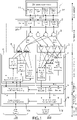
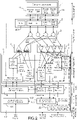
- the figure 2 illustrates the hardware implementation of the invention applied to a mode S radar having a four-pattern antenna.
- the figure shows the synoptic of the radar of the figure 1 increased by elements specific to the invention.
- the main elements of the invention applied to the Mode S radar are shown in broken bold lines on the picture 2 .
- the spatio-temporal management 6 transmits the position in azimuth 23 of the main lobe of the antenna to the permanent processing 21 of the Mode S asynchronous responses.
- a second added element 22 stores and correlates the data contained in the long ADS-B squitter responses (DF17) and the measurements of the characteristics of these squitter responses by the radar. In particular, it performs the calculation of the 3 antenna diagrams SUM, DIFF, CONT_Front and CONT_Back in elevation as well as the deviation measurement error in elevation by exploiting the position given in the long ADS-B squitters.
- This second processing is added in the multi-turn processing where the position of the target transmitted in the squitter with the Mode S address, time and position supplemented by the measured values with this same squitter response of the measured power on SUM, DIFF, CONT_Front and CONT_Back, deviation measurement and antenna azimuth.
- the antenna is of the LVA type. It comprises N bars, each bar comprising P dipoles, for example 35 bars with 11 elements each.
- the invention exploits the content of the DF17 messages which specifies the position (LAT-LONG) of the transponder and the detection and measurement of its position by the radar.
- the distribution of the energy received between the N bars allows the measurement of the position in azimuth and the distribution of the energy received between the dipoles of each bar defines the diagram in elevation.
- the invention With the aim of isolating localized degradation either at the level of the splitter between the bars, or at the level of a bar, or of a dipole of a bar, the invention accumulates the measurements by elevation slice. It is the asynchrony of the long ADS-B squitter (DF17) and the disparity of the targets in altitude and distance (therefore in elevation) which makes it possible to cover practically the entire antenna lobe over a given period (for example one day ).
- the invention consists in particular in measuring the misalignment with respect to the axis of the antenna per elevation slice of the ADS-B squitters received by the radar in its main beam, measure the error of the deviation measurement curve used by the radar for its deviation measurement function by difference between the position given in the ADS-B squitter and that measured simultaneously by deviation measurement by the radar on the same ADS-B squitter, then to integrate over a long period (daily for example) these errors per slice of elevation.
- the power measurements in each diagram associated with the ADS-B squitter make it possible to calculate the relative power of SUM, DIFF and CONT_Front versus SUM_max for the depointing of the ADS-B squitter in the lobe, then to integrate on a long period (daily) these measurements by slice of elevation.
- the principle consists in using the Fruits (asynchronous responses) which are the long ADS-B squitters received by the radar in its main beam corresponding to the cases of an aircraft present in the main lobe of the radar when it emits a squitter.
- the ADS-B long squitter DF17 intrinsically carries the Latitude-Longitude (LAT-LONG) position of the target.
- the ADS-B squitter When it is received, like any other Fruit, the ADS-B squitter is enriched with the powers received on the different diagrams of the radar antenna as well as the deviation value measured as for any response received in the radar lobe (this deviometric value having meaning only in the main beam, more precisely in the vicinity of the axis of the antenna, i.e. around 2.5° to +2.5° for an ATC antenna with a lobe at 3 dB from 2.4°).
- the invention only exploits the ADS-B squitters validated by the radar, that is to say using selective interrogations positively answered by the same target on the radar during its operational task of monitoring its air cover. of responsibility thereby avoiding taking into account ADS-B squitters from spoofers whose declared position may be false or from targets whose flight has shown various errors with previous radar detections.
- the invention performs a calculation by slice of elevations in order to take into account the effects of splaying of the diagrams of the antenna (therefore in particular of the deviation measurement function) in cosine of the elevation of the target with respect to the radar.
- all the asynchronous responses are enriched with the power measured according to each diagram.
- the mode S address is a unique identifier of the transponder and therefore allows in asynchronous processing as conventionally in synchronous processing to identify a target and to ensure by selective interrogation of the radar that the ADS-B squitter is indeed a real target in radar coverage.
- the invention does not take into account the ADS-B squitters considered doubtful, that is to say not validated by the selective interrogations of the radar.
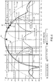
- the figure 5 illustrates the power received as a function of the distance from the target.
- the curves of the figure 4 representative of the antenna diagrams show that the power dynamic of the signals to be processed, in the main beam, is of the order of 25 dB to 35 dB relative between the diagrams.
- Curve 51 indicates the average power per target received (that is to say per plot) as a function of the distance from the target. This curve 51, typical of the descending radar balance, makes it possible to evaluate the power of the signal received from a target.
- the method according to the invention only uses nearby targets whose power level is at least 35 dB above the threshold 52 for detection and decoding of ADS-B responses by the radar. .
- the long ADS-B squitters taken into consideration for the invention are those received in the main beam of the radar, their level is close to that of the same target when it responds in synchronous mode to the radar. In practice, this leads for example to using for the measurement of the diagrams only the long ADS-B squitters whose target is within 50 Nm of the radar, this value being able to be adjusted by parameter by an operator.
- the figure 6 illustrates the principle of the invention by an example of sampling of the patterns of the antenna in reception at 1090 MHz by about ten squitters emitted by different targets.
- the diagrams are the same as those of the figure 4 described in the case of synchronous use, only the interrogation diagram 41 having been deleted.
- the invention advantageously exploits the ADS-B long squitters to measure with great precision, permanently, the patterns of the main beam of the antennas of the secondary radar, with targets of opportunity according to different elevations chosen in distance according to the type of measurement carried out.
- This figure shows a typical ATC or IFF antenna with 3 diagrams: SUM, DIFF and CONT_Front, represented respectively by curves 42, 43, 44.
- the dynamics of the signal (y-axis Y), given by the received level versus the radar measurement threshold, provides the required dynamics (close to 35dB).
- a long ADS-B squitter DF17 includes a datum, in particular the LAT-LONG position and the altitude.
- DIFF-relative (dB) and DIFF (in dBm), CONT-relative (dB) and CONT (in dBm) are defined analogously for DIFF and CONT diagrams.
- the figure 7 illustrates the accumulation of these values which makes it possible to reconstruct the SUM diagram (measured diagram 42"), the DIFF diagram (measured diagram 43") and the CONT diagram (measured diagram 44"), between -5° and +5°.
- the bold parts of the SUM, DIFF, CONT diagrams are obtained with approximately 18000 responses.
- the factory acceptance plots are made conventionally with a pitch pitch equal to approximately 0.05°.
- the duration of the analysis must be long enough (on the order of a day for example) in order to have enough samples in each cell (azimuth, elevation, deposit). Indeed, it is the targets according to their position relative to the radar in the site considered which sample the diagrams of the antenna therefore only the duration of the analysis makes it possible to collect enough measurements.
- the figure 8 presents a zoom on the useful part of the curve of the error measurement voltage as a function of the misalignment in the main lobe.
- This curve is stored inverted in the deviation table which is used by the radar, depending on the measurement of the DIFF/SUM ratio of a synchronous or asynchronous response received in the main lobe, to evaluate the misalignment of the latter vis -towards the axis of the antenna.
- the vertical dotted lines 81, 82 delimit the useful zone of the curve which is conventionally exploited by a radar associated with an LVA antenna of 2.4° at ⁇ 3 dB.
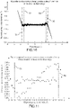
- the figure 9 presents the plot of the error curve in azimuth on a large number of responses (more than 8000) as a function of the depointing of the target in the main lobe.
- this begins to show a slight slope with errors of nearly +/-0.1° at the edge of the lobe, to be compared with the azimuth accuracy expected from a radar with a standard deviation of 0.08°.
- the deviation table is limited to the range between the dotted lines 91, 92, coherently it is normal for the error to increase significantly outside this zone not exploited by the radar in example.
- the invention establishes a template for the various antenna diagrams SUM, DIFF, CONT and deviation measurement error according to the factory layouts of the antenna (during factory acceptance) equipping the radar site.
- the method according to the invention compares the measurements carried out with the template and produces a summary of the points outside the template, weighting it by considering the quantity and the quality of the fruits used to measure the diagrams and the error measurement.
- This HUMS synthesis typically daily, makes it possible to assess potential ongoing degradation of the antenna (including cable and rotary joint).
- This permanent analysis of the three antenna diagrams and of the deviation measurement is carried out with respect to several templates. It makes it possible to quantify at the functional level a degradation in performance that may eventually declare the radar or the ADS-B receiver using the same aerial as degraded or even broken down.
- dedicated templates can be defined with the aim of detecting the usual degradations of the air with which will have been associated the deformations of the antenna diagrams consecutive to these degradations.
- an additional advantage of the invention is the following: the establishment of the error of the deviation function, daily for example, allows, when the latter remains within a tolerance template still acceptable by an operator, to correct the deviation table used by the radar to locate synchronous targets in azimuth in the beam and thus to always ensure good azimuthal precision of the radar at the onset of degradation of the aerial or aging of the aerial.
- the aerial being the assembly comprising at least the antenna 1, the antenna drop cables and the rotary joint.
- the figure 10 presents the plot of the new azimuth error curve according to the invention after calculation of the new deviation table on the same large number of responses (more than 8000) as a function of the depointing of the target in the main lobe. Note that this is almost flat, with errors all well below +/-0.05° peak to peak.
- the figure 11 presents a zoom on the useful part of the lobe by comparing the plots of the error curves in azimuth as a function of the misalignment of the target, by using either the old deviation table or the new one according to the invention on the same large number of responses (more than 8000).
Description
La présente invention concerne un procédé de mesure de diagrammes d'antenne et de la précision azimut de la fonction écartométrie de radars secondaires. Elle concerne également un radar secondaire mettant en œuvre un tel procédé.The present invention relates to a method for measuring antenna patterns and the azimuth precision of the deviation measurement function of secondary radars. It also relates to a secondary radar implementing such a method.
Le domaine privilégié de l'invention est le Contrôle du Trafic Aérien (ATC) pour lequel la performance du radar est fondamentale tant au niveau de la détection des aéronefs que de la localisation très précise des cibles en azimut jusqu'à plusieurs centaines de kilomètres.The preferred field of the invention is Air Traffic Control (ATC) for which the performance of the radar is fundamental both in terms of the detection of aircraft and the very precise location of targets in azimuth up to several hundred kilometers.
Ces performances de précision sont particulièrement liées à la qualité des diagrammes de l'antenne équipant les radars secondaires employés en ATC ou en IFF.These precision performances are particularly linked to the quality of the diagrams of the antenna equipping the secondary radars used in ATC or in IFF.
Dans la suite de la description, dans un but de simplification, on appellera par extension antenne l'ensemble constitué :
- principalement de l'antenne du radar de tout type, Large Vertical Aperture LVA ou poutre ;
- du joint tournant associant partie rotative et partie fixe du radar ;
- des câbles de la descente d'antenne.
- mainly radar antenna of any type, Large Vertical Aperture LVA or Beam;
- the rotating joint combining the rotating part and the fixed part of the radar;
- antenna drop cables.
Actuellement, la mesure de la précision azimut d'un radar secondaire nécessite une balise externe dont le radar exploite les réponses pour la localiser et par suite contrôler le bon fonctionnement de la fonction d'écartométrie du radar.Currently, the measurement of the azimuth precision of a secondary radar requires an external beacon whose responses the radar uses to locate it and consequently check the proper functioning of the radar deviation measurement function.
Une mesure plus indépendante du radar de la qualité des diagrammes du lobe principal d'une antenne (sensiblement compris entre -10° et +10° en ATC) installée sur un site radar nécessite à la fois :
- le passage en maintenance de la station, ce qui diminue la couverture radar au niveau système ;
- d'employer un outillage externe pour mesurer en réception (à 1090MHz) les diagrammes de l'antenne SUM, CONT et DIFF ;
- the maintenance of the station, which reduces the radar coverage at the system level;
- to use an external tool to measure in reception (at 1090MHz) the diagrams of the antenna SUM, CONT and DIFF;
En l'absence de mesures périodiques préventives des diagrammes d'antennes et de la précision azimut du radar, ou même entre deux sessions de mesures préventives, la dégradation de ces diagrammes n'est alors perçue par l'utilisateur que lorsque les performances du radar sont dégradées, quelquefois au point de ne plus remplir sa mission. Dans ce cas, l'interruption de service est alors imposée et la réparation de l'antenne est à effectuer en urgence sachant qu'il s'agit de la plus importante et compliquée tâche de maintenance d'un radar.In the absence of periodic preventive measurements of the antenna diagrams and the azimuth precision of the radar, or even between two sessions of preventive measurements, the degradation of these diagrams is then perceived by the user only when the performance of the radar are degraded, sometimes to the point of no longer fulfilling their mission. In this case, the interruption of service is then imposed and the repair of the antenna is to be carried out urgently knowing that it is about the most important and complicated task of maintenance of a radar.
On rappelle que l'écartométrie est une méthode de mesure de dépointage d'une cible, présente dans le faisceau principal, par rapport à l'axe de l'antenne et que le radar secondaire se devant d'assurer, dans sa mission première, la localisation, de toutes les cibles détectées, très précise à la fois en distance et azimut par rapport au radar, sa fonction d'écartométrie lui est fondamentale car contribuant directement à sa précision azimut.It is recalled that deviation measurement is a method of measuring the depointing of a target, present in the main beam, with respect to the axis of the antenna and that the secondary radar must ensure, in its primary mission, the location, of all the targets detected, very precise both in distance and azimuth with respect to the radar, its deviation measurement function is fundamental to it because it contributes directly to its azimuth precision.
Un document
Un but de l'invention est notamment de permettre de mesurer la précision azimutale des diagrammes d'antenne d'un radar secondaire, et par là-même d'évaluer leur dégradation.An object of the invention is in particular to make it possible to measure the azimuthal precision of the antenna patterns of a secondary radar, and thereby to evaluate their degradation.
A cet effet, l'invention a pour objet un procédé de mesure des diagrammes d'antenne et d'écartométrie par tranches d'élévation d'un radar secondaire, chaque diagramme étant associé à une voie de réception, caractérisé en ce que, sur une période de temps donnée :
- on détecte les réponses asynchrones non sollicitées, de type squitters ADS-B longs, émises par des cibles présentes dans l'environnement aérien dudit radar, chacun desdits squitters contenant une information de position 3 D de la cible qui l'émet ;
- pour chaque détection, on décode le squitter ADS-B longs pour vérifier que la cible détectée est localisée conformément à l'information de position contenue dans ledit squitter, les détections non conformes étant rejetées ;
- pour chaque détection retenue, l'heure de ladite détection, la valeur de l'azimut de l'axe du faisceau principal de ladite antenne, la tension d'écartométrie et la valeur de puissance reçue sur chacune desdites voies de réception SUM, DIFF, CONT_Front, CONT_Back sont associées à ladite détection, l'information de position contenue dans ledit squitter donnant par calcul la tranche d'élévation dans laquelle est située ladite détection ;
- the unsolicited asynchronous responses, of long ADS-B squitter type, transmitted by targets present in the air environment of said radar are detected, each of said squitters containing 3D position information of the target which transmits it;
- for each detection, the long ADS-B squitter is decoded to verify that the detected target is located in accordance with the position information contained in said squitter, non-compliant detections being rejected;
- for each detection retained, the time of said detection, the value of the azimuth of the axis of the main beam of said antenna, the deviation measurement voltage and the power value received on each of said reception channels SUM, DIFF, CONT_Front, CONT_Back are associated with said detection, the position information contained in said squitter giving by calculation the elevation slice in which said detection is located;
Ladite antenne comporte par exemple un des ensembles de diagrammes suivant :
- un diagramme somme (SUM), un diagramme différence (DIFF), un diagramme de contrôle pour rejeter des réponses de cibles face à l'antenne (CONT_Front) et un diagramme de contrôle pour rejeter des cibles à l'arrière de l'antenne (CONT_Back) ;
- un diagramme somme (SUM), un diagramme différence (DIFF), un diagramme de contrôle (CONT) ;
- un diagramme somme (SUM) et un diagramme différence et contrôle (DIFF/CONT).
- a sum diagram (SUM), a difference diagram (DIFF), a control diagram for rejecting responses from targets facing the antenna (CONT_Front) and a control diagram for rejecting targets behind the antenna ( CONT_Back);
- a sum diagram (SUM), a difference diagram (DIFF), a control diagram (CONT);
- a sum diagram (SUM) and a difference and control diagram (DIFF/CONT).
Dans un mode de mise en œuvre particulier, les réponses de type squitters ADS-B longs sont enrichies par des caractéristiques représentatives de l'acquisition desdites réponses, lesdites caractéristiques étant pour chaque réponse au moins l'une des caractéristiques suivantes :
- la puissance reçue selon chaque diagramme de ladite antenne ;
- l'écartométrie de la réponse dans le lobe principal de la dite antenne ;
- l'heure de la détection de ladite réponse ;
- l'azimut de l'axe du faisceau principal de ladite antenne lors de ladite détection.
- the power received according to each pattern of said antenna;
- the deviation measurement of the response in the main lobe of said antenna;
- the time of detection of said response;
- the azimuth of the axis of the main beam of said antenna during said detection.
Par exemple, pour chaque squitter reçu dans le faisceau principal, ledit procédé :
- exploite l'information contenue dans le squitter ;
- calcule la puissance relative puis l'erreur du gain des diagrammes de l'antenne en fonction du gisement :
- dans le même faisceau, ledit radar mesurant la puissance du plot synchrone, ladite puissance étant la valeur maximum du diagramme somme ;
- la réponse squitter ADS-B long étant enrichie d'une mesure de puissance sur les diagrammes somme, différence et contrôle, le procédé selon l'invention déduisant pour le gisement du squitter :
- ∘ SUM-relative (dB) = SUM (en dBm) - SUM_max (en dBm) ;
- ∘ DIFF-relative (dB) = DIFF (en dBm) - SUM_max (en dBm) ;
- ∘ CONT-relative (dB) = CONT (en dBm) - SUM_max (en dBm) ;
- l'erreur de gain de chaque diagramme est établie en comparant ces valeurs à celles de référence de l'invention (diagrammes mesurées soit lors de la recette du radar en usine, soit lors de l'acceptation du site radar) :
- ∘ SUM_err (dB) = SUM-relative (dB) - SUM-reference (dB) ;
- ∘ DIFF_err (dB) = DIFF-relative (dB) - DIFF-reference (dB) ;
- ∘ CONT_err (dB) = CONT-relative (dB) - CONT-reference (dB) ;
- calcule l'erreur d'écartométrie en tenant compte de la déformation du faisceau en élévation relative à l'antenne.
- exploits the information contained in the squitter;
- calculates the relative power then the gain error of the antenna patterns as a function of bearing:
- in the same beam, said radar measuring the power of the synchronous plot, said power being the maximum value of the sum diagram;
- the long ADS-B squitter response being enriched with a power measurement on the sum, difference and control diagrams, the method according to the invention deducing for the bearing of the squitter:
- ∘ SUM-relative (dB) = SUM (in dBm) - SUM_max (in dBm);
- ∘ DIFF-relative (dB) = DIFF (in dBm) - SUM_max (in dBm);
- ∘ CONT-relative (dB) = CONT (in dBm) - SUM_max (in dBm);
- the gain error of each diagram is established by comparing these values with those of reference of the invention (diagrams measured either during acceptance of the radar in the factory, or during acceptance of the radar site):
- ∘ SUM_err (dB) = SUM-relative (dB) - SUM-reference (dB);
- ∘ DIFF_err (dB) = DIFF-relative (dB) - DIFF-reference (dB);
- ∘ CONT_err (dB) = CONT-relative (dB) - CONT-reference (dB);
- calculates the deviation error taking into account the deformation of the beam in elevation relative to the antenna.
Pendant la durée de l'analyse, lesdites valeurs sont par exemple accumulées en fonction du gisement au fur et à mesure selon :
- l'azimut de ladite antenne ;
- l'élévation de ladite cible.
- the azimuth of said antenna;
- elevation of said target.
Sur ladite période donnée, on accumule par exemple dans des tables à trois entrées l'erreur d'écartométrie et l'erreur de chaque diagrammes, une table étant associée à l'erreur d'écartométrie et à l'erreur de chaque diagramme d'antenne, une entrée étant le gisement en fonction de l'axe du lobe principal de l'antenne, la seconde entrée étant l'élévation de la cible en fonction de l'horizontalité de l'antenne et la troisième entrée étant l'azimut antenne.Over said given period, for example, the deviation measurement error and the error of each diagram are accumulated in tables with three inputs, a table being associated with the deviation measurement error and the error of each flow diagram. antenna, one input being the bearing as a function of the main lobe axis of the antenna, the second input being the elevation of the target as a function of the horizontality of the antenna and the third input being the antenna azimuth .
Chaque cellule (gisement, élévation) de l'erreur d'écartométrie et de l'erreur de chaque diagramme est par exemple établie par des méthodes du type moyenne, histogramme ou autres.Each cell (bearing, elevation) of the deviation measurement error and of the error of each diagram is for example established by methods of the mean, histogram or other type.
Ladite période donnée est par exemple définie pour laisser apparaître des dégradations en cours desdits diagrammes.Said given period is for example defined to allow current degradations of said diagrams to appear.
Sous contrôle d'un opérateur ou automatiquement, ledit radar employant une table d'écartométrie pour localiser les cibles synchrones en azimut dans ledit faisceau principal, ladite table est par exemple corrigée sur la base des erreurs d'écartométrie mesurées afin d'assurer une bonne précision azimutale dudit radar lors d'une dégradation de l'ensemble de composants dit aérien.Under the control of an operator or automatically, said radar employing a deviometric table to locate synchronous targets in azimuth in said main beam, said table is for example corrected on the basis of the measured deviometric errors in order to ensure good azimuthal precision of said radar during degradation of the assembly of so-called aerial components.
L'antenne, équipant un radar secondaire du type ATC ou IFF, comporte par exemple au moins deux diagrammes. Ladite antenne est à balayage électronique, fixe ou tournante.The antenna, fitted to a secondary radar of the ATC or IFF type, comprises for example at least two diagrams. Said antenna is electronically scanned, fixed or rotating.
Les mesures de l'erreur d'écartométrie et des diagrammes d'antenne sont par exemple utilisées pour évaluer le niveau de dégradation de chaque élément de l'aérien : antenne, câbles de la descente d'antenne, joint tournant.Measurements of the deviation measurement error and antenna diagrams are used, for example, to assess the level of degradation of each element of the aerial: antenna, antenna drop cables, rotary joint.
La mesure desdits diagrammes est par exemple utilisée pour évaluer le niveau de dégradation de l'ensemble de composants dit aérien.The measurement of said diagrams is for example used to evaluate the level of degradation of the assembly of so-called aerial components.
L'invention a également pour objet un radar secondaire mettant en œuvre un tel procédé.The invention also relates to a secondary radar implementing such a method.
D'autres caractéristiques et avantages de l'invention apparaîtront à l'aide de la description qui suit, faite en regard de dessins annexés qui représentent :
- la
figure 1 , un exemple de synoptique d'un radar secondaire mode S ; - la
figure 2 , une illustration de la mise en œuvre matérielle de l'invention ; - la
figure 3 , une illustration d'un exemple d'antenne ATC ; - la
figure 4 , une illustration, par un exemple, du fonctionnement synchrone typique d'un radar secondaire ; - la
figure 5 , une illustration de la puissance reçue en fonction de la distance de la cible ; - la
figure 6 , une illustration du principe de l'invention par un exemple d'échantillonnage des diagrammes d'une antenne par des squitters, asynchrones, émis par différentes cibles ; - la
figure 7 , des exemples de diagrammes mesurés par le procédé selon l'invention ; - la
figure 8 , une courbe de tension d'écartométrie en fonction du dépointage de la cible dans le lobe principal ; - la
figure 9 , une courbe d'erreur de précision azimut du radar en fonction du dépointage de la cible dans le lobe principal ; - la
figure 10 , une nouvelle courbe d'erreur de précision azimut du radar en fonction du dépointage suite au calcul d'une nouvelle table d'écartométrique selon l'invention ; - la
figure 11 , un zoom sur la partie utile du lobe principal comparant l'erreur de précision azimut du radar en fonction du dépointage entre l'ancienne et la nouvelle table d'écartométrique selon l'invention.
- the
figure 1 , an example of a block diagram of a mode S secondary radar; - the
figure 2 , an illustration of the hardware implementation of the invention; - the
picture 3 - the
figure 4 , an illustration, by example, of the typical synchronous operation of a secondary radar; - the
figure 5 , an illustration of received power as a function of target range; - the
figure 6 , an illustration of the principle of the invention by an example of sampling of the diagrams of an antenna by squitters, asynchronous, emitted by different targets; - the
figure 7 , examples of diagrams measured by the method according to the invention; - the
figure 8 , an error measurement curve as a function of the misalignment of the target in the main lobe; - the
figure 9 , a radar azimuth accuracy error curve as a function of target misalignment in the main lobe; - the
figure 10 , a new radar azimuth precision error curve as a function of misalignment following the calculation of a new deviation table according to the invention; - the
figure 11 , a zoom on the useful part of the main lobe comparing the azimuth precision error of the radar as a function of the misalignment between the old and the new deviation table according to the invention.
En regard de la
Le principe du radar secondaire mode S (défini en détail par l'ICAO Annexe 10 vol.4) consiste à :
- émettre des interrogations sélectives :
- soit indiquant le destinataire : une seule cible désignée par son adresse Mode S ;
- soit indiquant l'identifiant de l'émetteur ;
- recevoir des réponses sélectives :
- soit indiquant l'identifiant de l'émetteur : la même adresse Mode S de la cible ;
- soit indiquant le destinataire : l'identifiant de l'interrogateur.
- issue selective queries:
- either indicating the recipient: a single target designated by its Mode S address;
- either indicating the identifier of the sender;
- receive selective responses:
- either indicating the identifier of the transmitter: the same Mode S address of the target;
- either indicating the recipient: the identifier of the interrogator.
Dans son emploi usuel, le radar secondaire fonctionne en mode synchrone, c'est-à-dire qu'il émet une interrogation et attend une réponse en cohérence avec celle-ci, ce qui lui permet de localiser par mesure (en azimut et distance) et d'identifier (par l'adresse mode S) la cible.In its usual use, the secondary radar operates in synchronous mode, i.e. it sends an interrogation and waits for a response consistent with it, which enables it to locate by measurement (in azimuth and distance ) and identify (by the mode S address) the target.
Pour effectuer cette tâche avec performance, le radar est équipé d'une antenne 1 (
un diagramme somme 11, noté par la suite SUM, pour interroger et détecter la réponse synchrone de la cible ;un diagramme différence 12, noté DIFF, pour localiser finement la cible dans le faisceau SUM ;- un premier diagramme de contrôle 15, noté CONT_Front, pour bloquer et réjecter les réponses issues de cibles face à l'antenne non présentes dans le faisceau principal de SUM ;
- un deuxième diagramme de contrôle 14, noté CONT_back, pour bloquer et réjecter les réponses issues de cibles au dos à l'antenne (donc forcément non présentes dans le faisceau principal de SUM).
- a sum diagram 11, hereinafter denoted SUM, for interrogating and detecting the synchronous response of the target;
- a difference diagram 12, denoted DIFF, to finely locate the target in the SUM beam;
- a first control diagram 15, denoted CONT_Front, to block and reject responses from targets facing the antenna not present in the main beam of SUM;
- a second control diagram 14, denoted CONT_back, to block and reject responses from targets with their backs to the antenna (therefore necessarily not present in the main beam of SUM).
Selon les missions et donc les performances attendues du radar les antennes peuvent être :
- de plusieurs diagrammes :
- 4 diagrammes : SUM, DIFF, CONT_Front & CONT_Back ;
- 3 diagrammes : SUM, DIFF, CONT (CONT_Front et CONT_Back sont regroupés au niveau de l'antenne) ;
- 2 diagrammes : SUM, DIFF/CONT (DIFF, CONT_Front & CONT_Back sont regroupés au niveau de l'antenne).
- de dimensions différentes :
- en largeur :
- ∘ ayant une grande largeur pour avoir un faisceau principal fin apportant un fort gain ainsi que pour être sélective et précise en azimut ;
- en hauteur :
- ∘ ayant une grande hauteur, de type Large Vertical Aperture (LVA) apportant du gain et une protection contre les réflexions sol (principalement en ATC) ;
- ∘ ayant une petite hauteur, de type « poutre » apportant une mobilité (principalement utilisée en IFF).
- en largeur :
- several diagrams:
- 4 charts: SUM, DIFF, CONT_Front &CONT_Back;
- 3 diagrams: SUM, DIFF, CONT (CONT_Front and CONT_Back are grouped at the antenna level);
- 2 diagrams: SUM, DIFF/CONT (DIFF, CONT_Front & CONT_Back are grouped at the antenna level).
- of different sizes:
- width :
- ∘ having a large width to have a fine main beam bringing a strong gain as well as to be selective and precise in azimuth;
- in height:
- ∘ having a great height, of the Large Vertical Aperture (LVA) type providing gain and protection against ground reflections (mainly in ATC);
- ∘ having a small height, of the "beam" type providing mobility (mainly used in IFF).
- width :
Alors que les diagrammes SUM et DIFF sont classiquement fins avec des lobes à 3dB entre 2,4° à 10°, les diagrammes CONT_Front et CONT_Back cherchent à couvrir pratiquement 180° chacun.While the SUM and DIFF diagrams are typically thin with 3dB lobes between 2.4° and 10°, the CONT_Front and CONT_Back diagrams seek to cover almost 180° each.
Les antennes peuvent aussi être :
- de diagramme fixe, dites « mécanique » et tournante ;
- de diagramme évolutif, à balayage électronique, dites « AESA » fixe ou tournante.
- fixed diagram, called "mechanical" and rotating;
- evolutionary diagram, with electronic scanning, called "AESA" fixed or rotating.
Dans la suite de la description, on décrit la configuration antennaire la plus complète, soit 4 diagrammes en antenne tournante, sachant que les autres configurations se traitent de façon similaire quel que soit le nombre de diagrammes d'antennes exploités que l'antenne soit tournante ou fixe. Pour simplifier la description, on pourra cependant utiliser la configuration à 3 diagrammes en utilisant CONT en tant que regroupement de CONT_Front et CONT_Back.In the rest of the description, we describe the most complete antenna configuration, i.e. 4 rotating antenna diagrams, knowing that the other configurations are treated in a similar way regardless of the number of antenna diagrams used whether the antenna is rotating or fixed. To simplify the description, however, the configuration with 3 diagrams can be used by using CONT as a grouping of CONT_Front and CONT_Back.
Dans son utilisation opérationnelle, le radar reçoit des réponses non sollicitées (sans interrogation associée de sa part), celles-ci sont nommées « False Reply Unsynchronized in Time » ou Fruit. Elles sont ainsi nommées car :
- elles ne sont pas attendues par le radar qui les rejette (« False ») ;
- elles sont des réponses très similaires à celles synchrones et issues des mêmes cibles dans la même couverture du radar, ayant même fréquence et même format de message (« Reply ») ;
- elles ne sont pas associées à une interrogation de ce radar, mais d'un autre radar ou même émise par la cible de façon périodique telles que les squitters ADS-B (« Unsynchronized in Time »).
- they are not expected by the radar which rejects them (“False”);
- they are replies very similar to those synchronous and originating from the same targets in the same radar coverage, having the same frequency and the same message format (“Reply”);
- they are not associated with an interrogation of this radar, but of another radar or even emitted by the target periodically such as ADS-B (“Unsynchronized in Time”) squitters.
De par leur caractéristique asynchrone les Fruits sont reçus par le radar sur tous ses diagrammes d'antenne.Due to their asynchronous characteristic, the Fruits are received by the radar on all its antenna diagrams.
Enfin, les Fruits Mode S sont tous identifiables par l'unique adresse Mode S associée à chaque cible.Finally, Mode S Fruits are all identifiable by the unique Mode S address associated with each target.
Alors que les Fruits générés par un radar secondaire sont actuellement traités comme des défauts qui doivent être filtrés avant traitement, l'invention exploite avantageusement les Fruits que sont les squitters ADS-B longs au cours du traitement pour mesurer la précision écartométrique du radar ainsi que les diagrammes d'antenne.While the Fruits generated by a secondary radar are currently treated as defects which must be filtered before processing, the invention advantageously exploits the Fruits which are the long ADS-B squitters at the course of processing to measure the radar's deviation accuracy as well as the antenna patterns.
En conclusion, la mesure des diagrammes du lobe principal d'une antenne s'effectue en continu sans aucune influence sur le fonctionnement opérationnel du radar et est applicable quel que soit le type des antennes décrites.In conclusion, the measurement of the diagrams of the main lobe of an antenna is carried out continuously without any influence on the operational functioning of the radar and is applicable whatever the type of antennas described.
Parmi les Fruits mode S que reçoit un radar les squitters ADS-B ne sont pas sollicités par un autre interrogateur (radar, WAM, ...) mais générés sans sollicitation par l'avion lui-même pour signaler sa présence et dans le cas des squitters ADS-B longs (DF17) pour de plus donner leur position calculée avec précision en exploitant les signaux GPS.Among the Mode S Fruits received by a radar, the ADS-B squitters are not requested by another interrogator (radar, WAM, etc.) but are generated without request by the aircraft itself to signal its presence and in the case long ADS-B squitters (DF17) to also give their position calculated with precision by exploiting the GPS signals.
Le principe fondamental du récepteur de squitters ADS-B longs utilisant le même protocole mode S (messages définis en détail par l'ICAO Annexe 10 vol.4) consiste à :
- recevoir des Réponses Sélectives Non Sollicitées donc Asynchrones :
- indiquant l'identifiant de l'émetteur : la même adresse Mode S (champ de 24bits) de la cible que celle transmise au radar lors des interrogations et réponses sélectives décrites ci-avant ;
- la nature du contenu du message (DF=17) est variable selon le champ TC du message :
- ∘ 1 à 4 "Aircraft identification"
- ∘ 5 à 8 "Surface position"
- ∘ 9 à 18 "Airborne position (Baro Alt)"
- ∘ 19 "Airborne velocities "
- ∘ 20 à 22 "Airborne position (GNSS Height)"
- ∘ 23 "Test message"
- ∘ 24 "Surface system status"
- ∘ 25 à 27 "Reserved"
- ∘ 28 "Extended squitter AC status"
- ∘ 29 "Target state and status (V.2)"
- ∘ 30 "Reserved "
- ∘ 31 "Aircraft Opération status".
- receive Unsolicited Selective Responses therefore Asynchronous:
- indicating the identifier of the transmitter: the same Mode S address (24-bit field) of the target as that transmitted to the radar during the selective interrogations and responses described above;
- the nature of the message content (DF=17) varies according to the TC field of the message:
- ∘ 1 to 4 "Aircraft identification"
- ∘ 5 to 8 "Surface position"
- ∘ 9 to 18 "Airborne position (Baro Alt)"
- ∘ 19 "Airborne velocities"
- ∘ 20 to 22 "Airborne position (GNSS Height)"
- ∘ 23 "Message test"
- ∘ 24 "Surface system status"
- ∘ 25 to 27 "Reserved"
- ∘ 28 "Extended squitter AC status"
- ∘ 29 "Target state and status (V.2)"
- ∘ 30 "Reserved"
- ∘ 31 "Aircraft Operation status".
La liste ci-dessus est donnée à titre d'exemple, elle est indicative et évolutive.The list above is given as an example, it is indicative and evolving.
L'invention exploite particulièrement les squitters DF17 du champ TC correspondant de 9 à 18 ou de 20 à 22 donnant la position en 3 dimensions de la cible équipée du transpondeur diffusant le squitter associé à une altitude soit barométrique soit GNSS.The invention particularly exploits the DF17 squitters of the corresponding TC field from 9 to 18 or from 20 to 22 giving the position in 3 dimensions of the target equipped with the transponder broadcasting the squitter associated with either a barometric or GNSS altitude.
Dans son emploi usuel, un récepteur ADS-B_in fonctionne donc en mode asynchrone, c'est-à-dire qu'il écoute sur 360° un message mode S très similaire à celui du radar pour la localisation (azimut et distance) et l'identification (adresse mode S) d'une cible.In its usual use, an ADS-B_in receiver therefore operates in asynchronous mode, i.e. it listens over 360° to a mode S message very similar to that of the radar for location (azimuth and distance) and the identification (mode S address) of a target.
Pour effectuer cette tâche avec performance, le récepteur ADS-B_in est équipé :
- soit d'une antenne omnidirectionnelle couvrant 360°, ce qui est une configuration courante ;
- soit de plusieurs antennes de large diagramme couvrant 360° au total:
- deux antennes de couverture supérieure 180° dos à dos, qui est la configuration la plus répandue ;
- plus rarement de trois antennes de couverture supérieure à 120° ou encore quatre antennes de couverture supérieure à 90° ;
- either an omnidirectional antenna covering 360°, which is a common configuration;
- or several wide diagram antennas covering 360° in total:
- two back-to-back 180° top coverage antennas, which is the most common configuration;
- more rarely three antennas with coverage greater than 120° or even four antennas with coverage greater than 90°;
Etant donné que le radar secondaire et le récepteur ADS-B exploitent des messages quasi identiques (même fréquence 1090MHz, même forme d'onde, même structure de données du message de la réponse) il est aisé d'intégrer au radar la fonction d'écoute des squitters ADS-B asynchrones en écoutant ceux-ci par les différents diagrammes de l'antenne du radar et cela principalement, mais pas uniquement, par le diagramme omnidirectionnel :
- par plusieurs récepteurs chacun associé à un diagramme de son antenne :
- pour une antenne à 4 diagrammes : SUM, DIFF, CONT_Front & CONT_Back ;
- pour une antenne à 3 diagrammes : SUM, DIFF, CONT ;
- pour une antenne à 2 diagrammes : SUM, DIFF/CONT.
- by several receivers each associated with a diagram of its antenna:
- for an antenna with 4 diagrams: SUM, DIFF, CONT_Front &CONT_Back;
- for an antenna with 3 diagrams: SUM, DIFF, CONT;
- for an antenna with 2 diagrams: SUM, DIFF/CONT.
Dans le contexte de l'invention le radar est équipé selon cette configuration, à savoir un récepteur associé à chaque diagramme de son antenne, qu'elle comporte quatre, trois ou deux diagrammes.In the context of the invention, the radar is equipped according to this configuration, namely a receiver associated with each diagram of its antenna, whether it comprises four, three or two diagrams.
Avant de décrire plus en détail l'invention, on décrit les éléments constitutifs du radar Mode S de la
- sur la partie gauche 100 par la génération des interrogations ;
- sur la partie droite 200 par le traitement synchrone des réponses associées,
- on the
left part 100 by the generation of the queries; - on the
right part 200 by the synchronous processing of the associated responses,
Les fonctions des principaux éléments sont rappelées ci-après :
L'antenne 1 assure le rayonnement des interrogations à 1030 MHz et des réponses en retour à 1090 MHz, selon les quatre diagrammes : SUM, DIFF, CONT_Front et CONT_Back, ou trois diagrammes (SUM, DIFF, CONT) ou selon deux diagrammes (SUM, DIFF/CONT).The functions of the main elements are listed below:
The
Un joint tournant 2 et des câbles de descente d'antenne, pour une antenne rotative, assurent :
- le couplage RF des signaux transmis à 1030 MHz et reçus à 1090 MHz indépendamment pour les quatre diagrammes entre la partie tournante et la partie fixe du radar ;
- la diffusion de la position en
azimut 201 de l'axe du lobe principal de l'antenne.
- the RF coupling of the signals transmitted at 1030 MHz and received at 1090 MHz independently for the four diagrams between the rotating part and the fixed part of the radar;
- the broadcast of the position in
azimuth 201 of the axis of the main lobe of the antenna.
Un traitement RF comporte :
- un duplexeur ou circulateur 3 assurant le couplage RF entre les signaux transmis à 1030 MHz et reçus à 1090 MHz indépendamment pour les quatre diagrammes ;
un émetteur 4 assurant :- la transmission des interrogations à 1030 MHz sur le diagramme SUM ;
- le blocage des transpondeurs en dehors du lobe SUM à 1030 MHz par les diagrammes CONT_Front et CONT_Back ;
- ceci pour les différents protocoles secondaires : IFF, SSR et Mode S ;
un récepteur 5 assurant la réception des réponses à 1090 MHz sur les quatre diagrammes SUM, DIFF, CONT_Front et CONT_Back, et le calcul de l'écartométrie pour les différents protocoles secondaires : IFF, SSR et Mode S.
- a duplexer or
circulator 3 ensuring the RF coupling between the signals transmitted at 1030 MHz and received at 1090 MHz independently for the four diagrams; - a
transmitter 4 providing:- the transmission of interrogations at 1030 MHz on the SUM diagram;
- the blocking of transponders outside the SUM lobe at 1030 MHz by the CONT_Front and CONT_Back diagrams;
- this for the various secondary protocols: IFF, SSR and Mode S;
- a
receiver 5 ensuring the reception of the responses at 1090 MHz on the four diagrams SUM, DIFF, CONT_Front and CONT_Back, and the calculation of the deviation measurement for the various secondary protocols: IFF, SSR and Mode S.
Un traitement temps réel comporte :
- une gestion spatio-
temporelle 6 assurant la gestion temps réel des périodes d'interrogations et d'écoutes associées pour les différents protocoles secondaires : IFF, SSR et Mode S ; - un traitement du
signal 7 assurant :- le traitement des réponses dans les périodes d'écoutes associées aux interrogations pour les différents protocoles secondaires : IFF, SSR et Mode S ;
- la détection et le décodage des réponses synchrones dans le lobe principal de l'antenne en exploitant les quatre diagrammes :
- ∘ SUM : pour détecter les réponses reçues dans le lobe principal ;
- ∘ DIFF : pour localiser finement en azimut les réponses reçues dans le lobe principal SUM et éventuellement pour la discrimination de réponses emmêlées ;
- ∘ CONT_Front et CONT_Back : pour réjecter les réponses reçues sur les lobes secondaires de SUM et DIFF dans le cas d'une détection dans le lobe principal de SUM.
- a spatio-
temporal management 6 providing real-time management of the associated interrogation and listening periods for the various secondary protocols: IFF, SSR and Mode S; -
signal processing 7 providing:- the processing of the responses in the listening periods associated with the interrogations for the various secondary protocols: IFF, SSR and Mode S;
- the detection and the decoding of the synchronous responses in the main lobe of the antenna by exploiting the four diagrams:
- ∘ SUM: to detect responses received in the main lobe;
- ∘ DIFF: to finely locate in azimuth the responses received in the SUM main lobe and possibly for the discrimination of entangled responses;
- ∘ CONT_Front and CONT_Back: to reject the responses received on the secondary lobes of SUM and DIFF in the event of a detection in the main lobe of SUM.
Un traitement dans le lobe principal de l'antenne comporte :
une gestion 8 des cibles présentes dans le lobe, assurant :- la préparation des transactions (interrogations et réponses) à effectuer dans le prochain lobe pour les différents protocoles secondaires IFF, SSR et Mode S ;
- le placement des interrogations et réponses Mode S dans la future période « Roll call » en fonction de l'état des transactions venant d'être effectuées ;
- des extracteurs 9 assurant la constitution de plots pour chacun des différents protocoles secondaires IFF, SSR et Mode S, à partir des réponses synchrones reçues dans le lobe selon le protocole employé lors des interrogations.
-
management 8 of the targets present in the lobe, ensuring:- the preparation of the transactions (interrogations and responses) to be carried out in the next lobe for the various secondary protocols IFF, SSR and Mode S;
- the placing of Mode S interrogations and responses in the future “Roll call” period according to the status of the transactions that have just been carried out;
-
extractors 9 ensuring the constitution of plots for each of the various secondary protocols IFF, SSR and Mode S, from the synchronous responses received in the lobe according to the protocol used during the interrogations.
Un traitement multi tours 10 comporte :
une gestion 101 des tâches Mode S à effectuer avec les cibles dans la couverture, assurant la prédiction de positions des cibles (rendez-vous d'antenne) et la préparation des tâches à effectuer avec ces positions selon les demandes internes, externes et l'état des transactions des tours précédents ;- une association des plots
et un pistage 102 des cibles dans la couverture assurant le pistage des cibles pour améliorer les performances (élimination des faux plots, contrôle de données décodées notamment) et pour prédire la position future de celles-ci.
-
management 101 of the Mode S tasks to be performed with the targets in the coverage, ensuring the prediction of target positions (antenna rendezvous) and the preparation of the tasks to be performed with these positions according to internal and external requests and the status of transactions from previous rounds; - an association of the plots and a tracking 102 of the targets in the coverage ensuring the tracking of the targets to improve performance (elimination of false plots, control of decoded data in particular) and to predict the future position of the latter.
Une interface avec les utilisateurs permet la prise en compte par le radar de différentes requêtes et la visualisation des plots et des poursuites de cibles.An interface with users allows the radar to take into account different requests and the visualization of plots and target tracking.
Le principe d'interrogation sélective du mode S basé sur l'interrogation au tour suivant en utilisant la prédiction de position effectuée à partir des mesures antérieures est donc conceptuellement très sensible à la précision de ces mesures. Une erreur de position mesurée induit une erreur de position prédite du radar mode S au tour suivant pouvant conduire lors de celui-ci :
- soit à des interrogations sélectives inutiles car mal positionnées en azimut relativement à la position réelle de la cible ;
- soit au pire cas à la non détection de la cible dans ce tour.
- either to useless selective interrogations because they are poorly positioned in azimuth relative to the real position of the target;
- or in the worst case to the non-detection of the target in this turn.
Il est donc très important de « monitorer » la précision de la mesure azimutale du radar basée sur l'emploi de l'écartométrie.It is therefore very important to "monitor" the precision of the azimuthal measurement of the radar based on the use of deviation measurement.
La
Alors que le fonctionnement d'un radar Mode S est synchrone, on voit que les traitements ajoutés 21, 22 ne sont pas liés à l'émission et n'exploitent que la position en azimut de l'axe du lobe principal de l'antenne 23.While the operation of a Mode S radar is synchronous, it can be seen that the added
La plupart des éléments restent inchangés, vérifiant en cela à la fois :
- la non intrusion de l'invention dans le fonctionnement opérationnel du radar Mode S ;
- la mesure utilisant les mêmes éléments que ceux que le radar exploite via le même récepteur :
- antenne ;
- joint tournant ;
- câbles de descente d'antenne.
- the non-intrusion of the invention into the operational functioning of the Mode S radar;
- the measurement using the same elements as those used by the radar via the same receiver:
- antenna;
- Turning joint ;
- antenna drop cables.
Un premier traitement est ajouté 21 pour traiter la réception des squitters ADS-B. Il assure un traitement permanent des réponses asynchrones en Mode S (indépendamment des périodes d'écoutes associées aux interrogations), ce traitement 21 assure la détection et le décodage des réponses asynchrones en exploitant séparément mais également les quatre diagrammes d'antennes : SUM, DIFF, CONT_Front et CONT_Back pour :
- détecter toutes les réponses reçues, asynchrones et synchrones ;
- décoder les réponses pour en extraire l'adresse Mode S ;
- pour enrichir chaque réponse décodée de ses caractéristiques, notamment :
- l'heure de détection ;
- l'azimut du lobe principal de l'antenne lors de la détection ;
- la puissance reçue dans les diagrammes SUM, DIFF, CONT_Front et CONT_Back ;
- l'écartométrie de la réponse ADS-B c'est-à-dire la mesure du dépointage de la réponse vis-à-vis de l'axe de l'antenne.
- detect all received responses, asynchronous and synchronous;
- decode the responses to extract the Mode S address therefrom;
- to enrich each decoded response with its characteristics, in particular:
- detection time;
- the azimuth of the main lobe of the antenna during detection;
- the power received in the SUM, DIFF, CONT_Front and CONT_Back diagrams;
- the deviation measurement of the ADS-B response, that is to say the measurement of the misalignment of the response with respect to the axis of the antenna.
A cet effet, la gestion spatio-temporelle 6 transmet la position en azimut 23 du lobe principal de l'antenne au traitement permanent 21 des réponses asynchrones Mode S.To this end, the spatio-
On obtient en parallèle, avantageusement, un enrichissement des réponses synchrones par les puissances mesurées sur les diagrammes SUM, DIFF, CONT_Front et CONT_Back complétées par l'écartométrie.In parallel, an enrichment of the synchronous responses is advantageously obtained by the powers measured on the SUM, DIFF, CONT_Front and CONT_Back diagrams supplemented by the deviation measurement.
Au niveau des extracteurs 9, on obtient également un enrichissement des plots Mode S de la puissance mesurée sur SUM.At the level of the
Un deuxième élément ajouté 22 stocke et corrèle les données contenues dans les réponses squitters ADS-B longs (DF17) et les mesures des caractéristiques de ces réponses squitters par le radar. Il effectue notamment le calcul des 3 diagrammes d'antenne SUM, DIFF, CONT_Front et CONT_Back en élévation ainsi que l'erreur d'écartométrie en élévation en exploitant la position donnée dans les squitters ADS-B longs. Ce deuxième traitement est ajouté dans le traitement multi-tours où la position de la cible transmise dans le squitter avec l'adresse Mode S, heure et position complétées par les valeurs mesurées avec cette même réponse squitter de la puissance mesurée sur SUM, DIFF, CONT_Front et CONT_Back, écartométrie et azimut d'antenne.A second added
Ce deuxième élément ajouté 22 met en œuvre le principe de l'invention qui consiste à exploiter le fait que les squitters ADS-B longs :
- sont par nature asynchrones entre la période des squitters ADS-B et la rotation du radar;
- étant reçus à tout moment, ils échantillonnent donc les diagrammes du faisceau principal de l'antenne à différents gisements ;
- étant émis par différentes cibles, ils échantillonnent les diagrammes du faisceau principal de l'antenne à différentes élévations, celles des cibles les ayant générées ;
- transmettent une mesure de position précise autre que celle du radar (position GPS du squitter long ADS-B) ;
- permettent d'effectuer la mesure de type radar sur le squitter même.
- are inherently asynchronous between the ADS-B squitter period and the radar rotation;
- being received at any time, they therefore sample the diagrams of the main beam of the antenna at different bearings;
- being emitted by different targets, they sample the diagrams of the main beam of the antenna at different elevations, those of the targets having generated them;
- transmit a precise position measurement other than that of the radar (GPS position of the ADS-B extended squitter);
- enable radar-like measurement to be performed on the squitter itself.
Avant de décrire plus en détail l'invention, on rappelle le principe de l'invention en regard de la représentation d'une antenne ATC d'un radar secondaire illustrée par la
Dans le but d'isoler une dégradation localisée au niveau soit du répartiteur entre les barreaux, soit au niveau d'un barreau, soit d'un dipôle d'un barreau, l'invention accumule les mesures par tranche d'élévation. C'est l'asynchronisme du squitter ADS-B long (DF17) et la disparité des cibles en altitude et distance (donc en élévation) qui permet de parcourir pratiquement la totalité du lobe d'antenne sur une période donnée (par exemple un jour).With the aim of isolating localized degradation either at the level of the splitter between the bars, or at the level of a bar, or of a dipole of a bar, the invention accumulates the measurements by elevation slice. It is the asynchrony of the long ADS-B squitter (DF17) and the disparity of the targets in altitude and distance (therefore in elevation) which makes it possible to cover practically the entire antenna lobe over a given period (for example one day ).
Ainsi, comme cela sera décrit par la suite l'invention consiste notamment à mesurer le dépointage vis-à-vis de l'axe de l'antenne par tranche d'élévation des squitters ADS-B reçus par le radar dans son faisceau principal, mesurer l'erreur de la courbe d'écartométrie utilisée par le radar pour sa fonction écartométrie par différence entre la position donnée dans le squitter ADS-B et celle mesurée simultanément par écartométrie par le radar sur le même squitter ADS-B, puis à intégrer sur une période longue (quotidiennement par exemple) ces erreurs par tranche d'élévation.Thus, as will be described below, the invention consists in particular in measuring the misalignment with respect to the axis of the antenna per elevation slice of the ADS-B squitters received by the radar in its main beam, measure the error of the deviation measurement curve used by the radar for its deviation measurement function by difference between the position given in the ADS-B squitter and that measured simultaneously by deviation measurement by the radar on the same ADS-B squitter, then to integrate over a long period (daily for example) these errors per slice of elevation.
De façon similaire, les mesures de la puissance dans chaque diagramme associées au squitter ADS-B permettent de calculer la puissance relative de SUM, DIFF et CONT_Front versus SUM_max pour le dépointage du squitter ADS-B dans le lobe, puis d'intégrer sur une période longue (quotidiennement) ces mesures par tranche d'élévation.Similarly, the power measurements in each diagram associated with the ADS-B squitter make it possible to calculate the relative power of SUM, DIFF and CONT_Front versus SUM_max for the depointing of the ADS-B squitter in the lobe, then to integrate on a long period (daily) these measurements by slice of elevation.
De cette façon, sans interférence avec le fonctionnement opérationnel du radar et sans balise, uniquement en utilisant des aéronefs équipés d'ADS-B d'opportunités, on peut automatiquement détecter une détérioration en cours notamment de la précision en azimut du radar indépendamment par tranche d'élévations ou plus globalement du faisceau principal du radar.In this way, without interference with the operational functioning of the radar and without beacon, only by using aircraft equipped with ADS-B of opportunities, one can automatically detect a deterioration in progress in particular of the azimuth precision of the radar independently by slice elevations or more globally of the main beam of the radar.
Le principe consiste à utiliser les Fruits (réponses asynchrones) que sont les squitters ADS-B longs reçus par le radar dans son faisceau principal correspondant aux cas d'un avion présent dans le lobe principal du radar au moment où il émet un squitter. En effet, de par sa mission première de localisation d'une cible, le squitter ADS-B long DF17 porte intrinsèquement la position Latitude-Longitude (LAT-LONG) de la cible.The principle consists in using the Fruits (asynchronous responses) which are the long ADS-B squitters received by the radar in its main beam corresponding to the cases of an aircraft present in the main lobe of the radar when it emits a squitter. Indeed, due to its primary mission of locating a target, the ADS-B long squitter DF17 intrinsically carries the Latitude-Longitude (LAT-LONG) position of the target.
Lors de sa réception, comme tout autre Fruit, le squitter ADS-B est enrichi des puissances reçues sur les différents diagrammes de l'antenne radar ainsi que de la valeur d'écartométrie mesurée comme pour toute réponse reçue dans le lobe du radar (cette valeur d'écartométrie n'ayant de sens que dans le faisceau principal plus précisément au voisinage de l'axe de l'antenne soit aux environs de 2,5° à +2,5° pour une antenne ATC de lobe à 3 dB de 2,4°). L'invention n'exploite que les squitters ADS-B validés par le radar c'est-à-dire à l'aide d'interrogations sélectives positivement répondues par la même cible au radar lors de sa tâche opérationnelle de surveillance de sa couverture aérienne de responsabilité évitant en cela la prise en compte de squitters ADS-B issus de spoofer dont la position déclarée peut-être fausse ou de cible dont le vol a montré des erreurs diverses avec les détections antérieures du radar.When it is received, like any other Fruit, the ADS-B squitter is enriched with the powers received on the different diagrams of the radar antenna as well as the deviation value measured as for any response received in the radar lobe (this deviometric value having meaning only in the main beam, more precisely in the vicinity of the axis of the antenna, i.e. around 2.5° to +2.5° for an ATC antenna with a lobe at 3 dB from 2.4°). The invention only exploits the ADS-B squitters validated by the radar, that is to say using selective interrogations positively answered by the same target on the radar during its operational task of monitoring its air cover. of responsibility thereby avoiding taking into account ADS-B squitters from spoofers whose declared position may be false or from targets whose flight has shown various errors with previous radar detections.
L'invention exploite donc avantageusement les squitters ADS-B longs dont la position en gisement par rapport à l'axe de l'antenne les situe dans le faisceau principal (paramètre dépendant du type d'antenne ATC ou IFF) Pour chaque squitter ADS-B long, l'invention calcule donc :
- son gisement avec précision en exploitant la position LAT-LONG du squitter et celle LAT-LONG du radar donnant ainsi son dépointage dans le faisceau de l'antenne du radar ;
- sa puissance relative mesurée des diagrammes SUM, DIFF et CONT_Front versus SUM_max du plot synchrone quasi simultané du squitter par la même chaine de réception du radar (nécessaire pour la fonction détection du radar) ;
- sa tension d'écartométrie mesurée par la même chaine de réception du radar (nécessaire pour la fonction de localisation en azimut du radar) ;
- l'erreur avec les courbes théoriques de l'antenne :
- selon l'élévation de la cible relativement à la position du radar ;
- selon l'azimut du squitter ;
- ∘ en amplitude relative pour les diagrammes SUM, DIFF et CONT versus SUM_max ;
- ∘ en écartométrie en référence à la table d'écartométrie donnant sur la même réponse sans interférence avec le fonctionnement opérationnel du radar le dépointage mesuré de la cible fonction de la tension d'écartométrie de la réponse.
- its bearing with precision by exploiting the LAT-LONG position of the squitter and that of the radar, thus giving its misalignment in the beam of the radar antenna;
- its measured relative power of the SUM, DIFF and CONT_Front diagrams versus SUM_max of the quasi-simultaneous synchronous plot of the squitter by the same radar reception chain (necessary for the radar detection function);
- its deviation measurement voltage measured by the same radar reception chain (necessary for the radar's azimuth location function);
- the error with the theoretical curves of the antenna:
- according to the elevation of the target relative to the position of the radar;
- according to the azimuth of the squitter;
- ∘ in relative amplitude for the SUM, DIFF and CONT diagrams versus SUM_max;
- ∘ in deviation measurement with reference to the deviation measurement table giving the same response without interference with the operational functioning of the radar the measured misalignment of the target as a function of the deviation measurement voltage of the response.
Il est à noter que pour étendre la plage de mesures et ainsi améliorer la précision de ce monitoring des diagrammes du faisceau principal, l'invention effectue un calcul par tranche d'élévations afin de tenir compte des effets d'évasement des diagrammes de l'antenne (donc notamment de la fonction d'écartométrie) en cosinus de l'élévation de la cible par rapport au radar.It should be noted that in order to extend the range of measurements and thus improve the precision of this monitoring of the diagrams of the main beam, the invention performs a calculation by slice of elevations in order to take into account the effects of splaying of the diagrams of the antenna (therefore in particular of the deviation measurement function) in cosine of the elevation of the target with respect to the radar.
Pour garantir une bonne précision des mesures élémentaires on exploite par exemple :
- les squitters de fort niveau (à courte portée) afin de limiter l'effet du bruit du récepteur tout en assurant une dynamique suffisante pour la mesure des faisceaux SUM, DIFF et CONT_Front ;
- les squitters de cible à courte et moyenne portée (selon l'élévation) pour optimiser la mesure d'erreur d'écartométrie en minimisant l'influence de la précision de position de la cible transmise par celle-ci lors de la détection du squitter ADS-B (latence variable entre la position GPS mesurée du squitter et l'heure de réception du squitter par le radar).
- high level squitters (at short range) in order to limit the effect of receiver noise while ensuring sufficient dynamic range for the measurement of the SUM, DIFF and CONT_Front beams;
- target squitters at short and medium range (depending on elevation) to optimize the error measurement of deviation measurement by minimizing the influence of the position accuracy of the target transmitted by it during the detection of the ADS squitter -B (variable latency between the measured GPS position of the squitter and the time of reception of the squitter by the radar).
L'accumulation de ces mesures pendant une durée importante permet de couvrir toutes les valeurs d'élévations, d'azimuts et de gisements qu'exploite le radar et ainsi d'améliorer la précision des calculs d'erreurs selon les 3 axes retenus. De plus, l'accumulation de ces erreurs (écartométrie et amplitude fonction du gisement) par tranche d'azimut (au pas du degré par exemple) permet de faire apparaitre des singularités liées à un azimut donné. Ces erreurs sont analysées (par des moyens automatiques par exemple). Si le résultat d'analyse estime un nombre d'erreurs trop important (en amplitude comme en écartométrie) on peut émettre des hypothèses de source de la dégradation :
- si elle ne dépend pas de l'azimut du squitter ni du gisement ni de l'élévation :
- il peut s'agir d'une détérioration des câbles de descente d'antenne ;
- si elle dépend de l'azimut du squitter mais pas du gisement ni de l'élévation :
- il peut s'agir d'une détérioration du joint tournant associant partie fixe et partie rotative de l'antenne du radar ;
- si elle dépend du gisement mais pas de l'azimut du squitter ni de l'élévation :
- il peut s'agir d'une détérioration d'un dipôle vertical de l'antenne ou du répartiteur de l'antenne ;
- si elle dépend du gisement et de l'élévation mais pas de l'azimut du squitter :
- il peut s'agir d'une détérioration d'un élément rayonnant d'un dipôle vertical de l'antenne.
- if it does not depend on the azimuth of the squitter nor on the bearing nor on the elevation:
- it may be a deterioration of the antenna drop cables;
- if it depends on the azimuth of the squitter but not on bearing or elevation:
- it may be a deterioration of the rotating joint associating the fixed part and the rotating part of the antenna of the radar;
- if it depends on bearing but not on squitter azimuth or elevation:
- it may be a deterioration of a vertical dipole of the antenna or of the antenna distributor;
- if it depends on bearing and elevation but not on squitter azimuth:
- it may be a deterioration of a radiating element of a vertical dipole of the antenna.
D'autres hypothèses de sources de dégradation peuvent être émises.Other hypotheses of sources of degradation can be made.
Ainsi, une analyse permanente de ces mesures permet d'alerter automatiquement afin de prévoir si nécessaire une opération de réparation pouvant être programmée avant que les performances du radar se dégradent dans une approche de type HUMS (« Health and Usage Monitoring Systems »).Thus, a permanent analysis of these measurements makes it possible to alert automatically in order to plan, if necessary, a repair operation that can be programmed before the performance of the radar deteriorates in a HUMS (Health and Usage Monitoring Systems) type approach.
En ce qui concerne le décodage des réponses « squitter ADS-B long », le Chapitre 3 de l'Annexe 10 - Télécommunications aéronautiques - donne le récapitulatif des formats de réponse (descendants) mode S
Les squitters ADS-B longs (DF17 et DF18) sont bien d'un format de message identique aux réponses synchrones que traite un radar. Ainsi, l'emploi d'un traitement similaire aux réponses asynchrones comme aux réponses synchrones permet d'obtenir des mesures de diagrammes identiques selon les deux natures de messages et ainsi de pouvoir en déduire des conclusions communes à savoir qu'une dégradation de l'antenne mesurée par les réponses asynchrones est complètement applicable aux réponses synchrones.With regard to the decoding of "long ADS-B squitter" responses,
Long ADS-B squitters (DF17 and DF18) have a message format identical to the synchronous responses processed by a radar. Thus, the use of a treatment similar to the asynchronous responses as to the synchronous responses makes it possible to obtain measurements of identical diagrams according to the two natures of messages and thus to be able to deduce common conclusions therefrom, namely that a degradation of the antenna measured by asynchronous responses is completely applicable to synchronous responses.
La détection des réponses par un radar selon l'invention diffère selon que ces réponses sont synchrones ou asynchrones comme le tableau 1 ci-dessous le résume selon les diagrammes de l'antenne, les données numériques étant données à titre d'exemple :
Selon l'invention toutes les réponses asynchrones sont enrichies de la puissance mesurée selon chaque diagramme.According to the invention, all the asynchronous responses are enriched with the power measured according to each diagram.
Les différentes réponses mode S, synchrones comme asynchrones, sont très similaires en ce qui concerne l'adresse mode S :
- soit dans le champ parité ;
- soit dans le champ data.
- either in the parity field;
- either in the data field.
L'adresse mode S est un identifiant unique du transpondeur et permet donc en traitement asynchrone comme classiquement en traitement synchrone d'identifier une cible et de s'assurer par une interrogation sélective du radar que le squitter ADS-B est bien une cible réelle dans la couverture du radar. L'invention ne pas prend pas en compte les squitters ADS-B considérés comme douteux c'est-à-dire non validés par les interrogations sélectives du radar.The mode S address is a unique identifier of the transponder and therefore allows in asynchronous processing as conventionally in synchronous processing to identify a target and to ensure by selective interrogation of the radar that the ADS-B squitter is indeed a real target in radar coverage. The invention does not take into account the ADS-B squitters considered doubtful, that is to say not validated by the selective interrogations of the radar.
La
- SUM pour :
- la génération des interrogations vers le transpondeur (courbe 41) avec les interrogations 41' ;
- la détection des réponses du transpondeur (courbe 42) avec les réponses 42' ;
- DIFF pour :
- la localisation des réponses vis-à-vis de l'axe de l'antenne (courbe 43) ;
- pour certains types de radar, la discrimination de réponses emmêlées ;
- CONT_Front pour la délimitation des réponses à traiter dans le faisceau de l'antenne (courbe 44) :
- ISLS : Bloquer à l'émission (1030MHz) les transpondeurs en dehors du cœur du faisceau principal (voir l'étoile sur la
figure 4 correspondant à une interrogation refusée par le transpondeur) ; - RSLS : Réjecter à la réception (1090MHz) les réponses en dehors du cœur du faisceau principal.
- ISLS : Bloquer à l'émission (1030MHz) les transpondeurs en dehors du cœur du faisceau principal (voir l'étoile sur la
- SUM for:
- the generation of the interrogations towards the transponder (curve 41) with the interrogations 41';
- the detection of the responses from the transponder (curve 42) with the responses 42';
- DIFF for:
- the location of the responses with respect to the axis of the antenna (curve 43);
- for certain types of radar, the discrimination of entangled responses;
- CONT_Front for the delimitation of the responses to be processed in the antenna beam (curve 44):
- ISLS: Block transmission (1030MHz) of transponders outside the core of the main beam (see the star on the
figure 4 corresponding to an interrogation refused by the transponder); - RSLS: Reject on reception (1090MHz) responses outside the core of the main beam.
- ISLS: Block transmission (1030MHz) of transponders outside the core of the main beam (see the star on the
La
La
Lorsque le faisceau principal du radar éclaire des cibles, celles-ci sont interrogées sélectivement par le radar comme le montre la
Cette figure montre une antenne ATC ou IFF typique de 3 diagrammes : SUM, DIFF et CONT_Front, représentés respectivement par les courbes 42, 43, 44.This figure shows a typical ATC or IFF antenna with 3 diagrams: SUM, DIFF and CONT_Front, represented respectively by
A un instant donné les différentes cibles, présentes dans un azimut de -5° à +5° de l'axe de l'antenne, peuvent émettre des squitters longs 61. Chaque squitter détecté dans le lobe est enrichit de :
- ses niveaux reçus sur les 3
diagrammes SUM 42, à un niveau 611 sur le diagramme DIFF 43 et à un niveau 612 sur le diagramme CONT_Front 44 ; - sa tension d'écartométrie calculée par le radar à partir des signaux de la réponse reçue sur DIFF et SUM ;
- son gisement versus l'axe de l'antenne (axe des abscisses X).
- its levels received on the 3 diagrams 42, 43, 44 - thus a squitter is received at
level 61 on the SUM diagram 42, at alevel 611 on the DIFF diagram 43 and at alevel 612 on the CONT_Front diagram 44; - its deviation measurement voltage calculated by the radar from the response signals received on DIFF and SUM;
- its bearing versus the axis of the antenna (axis of abscissas X).
Selon la distance de la cible, la dynamique du signal (axe des ordonnées Y), donnée par le niveau reçu versus le seuil de mesure du radar, permet d'avoir la dynamique requise (voisine de 35dB).Depending on the distance from the target, the dynamics of the signal (y-axis Y), given by the received level versus the radar measurement threshold, provides the required dynamics (close to 35dB).
Chaque squitter étant caractérisé par l'adresse mode S de la cible :
- certains squitters donnent la position LAT-LONG de la cible ;
- d'autres donnent l'altitude de la cible (barométrique ou GNSS).
- some squitters give the LAT-LONG position of the target;
- others give the altitude of the target (barometric or GNSS).
L'asynchronisme entre :
- la position des cibles en azimut et élévation ;
- la rotation du faisceau du radar ;
- l'émission spontanée des squitters ADS-B longs par les cibles ;
- en gisement ;
- en élévation (déduite de la position LAT-LONG donnant la distance et l'altitude de la cible) ;
- en azimut de l'axe du faisceau d'antenne.
- the position of the targets in azimuth and elevation;
- rotation of the radar beam;
- the spontaneous emission of long ADS-B squitters by the targets;
- in deposit;
- in elevation (deduced from the LAT-LONG position giving the distance and altitude of the target);
- in azimuth from the axis of the antenna beam.
L'accumulation des mesures issues des squitters ADS-B est par ailleurs effectuée. A cet effet, l'invention piste tous les squitters ADS-B longs (asynchrones) afin de construire des pistes ADS-B, de façon analogue aux pistes synchrones du radar. Ces pistes se caractérisent principalement par :
- l'adresse mode S ;
- la position courante de la cible et son vecteur vitesse en 3D (azimut, distance, altitude) ;
- la puissance courante de la cible ;
- l'utilisation possible de cette piste par le procédé selon l'invention.
- the mode S address;
- the target's current position and its 3D velocity vector (azimuth, distance, altitude);
- the target's current power;
- the possible use of this track by the method according to the invention.
Même si un squitter d'une cible n'est pas reçu dans le faisceau principal de l'antenne, il est pisté afin d'enrichir la piste des données citées ci-avant.Even if a squitter from a target is not received in the main beam of the antenna, it is tracked in order to enrich the track with the data cited above.
En effet, selon la valeur du TC, un squitter ADS-B long DF17 comporte une donnée, notamment la position LAT-LONG et l'altitude.Indeed, depending on the value of the TC, a long ADS-B squitter DF17 includes a datum, in particular the LAT-LONG position and the altitude.
Pour chaque squitter utilisable (validé par le radar) reçu dans le faisceau principal (dépointé par exemple d'au plus -10° à 10° en gisement de l'axe de l'antenne lors de sa détection, sachant que cette plage angulaire n'est pas limitative, l'invention pouvant s'appliquer sur -180° à 180°), le procédé selon l'invention :
- exploite l'information contenue dans le squitter ;
- complète l'information manquante à partir des données de sa piste ;
- calcule la puissance relative puis l'erreur du gain des diagrammes de l'antenne en fonction du gisement :
- dans le même faisceau le radar mesure la puissance du plot synchrone (voir la
figure 4 ) : c'est la valeur SUM_max (en dBm) pouvant être obtenue par cette configuration radar à cette distance de la cible ; - la réponse du squitter ADS-B long est enrichie d'une mesure de puissance (en dBm) sur les diagrammes SUM, DIFF et CONT, le procédé selon l'invention déduisant pour le gisement du squitter :
- ∘ SUM-relative (dB) = SUM (en dBm) - SUM_max (en dBm) ;
- ∘ DIFF-relative (dB) = DIFF (en dBm) - SUM_max (en dBm) ;
- ∘ CONT-relative (dB) = CONT (en dBm) - SUM_max (en dBm) ; SUM-relative (dB), SUM (en dBm) et SUM_max (en dBm) sont définis comme suit : les courbes en
figure 4 (ou enfigure 6 ) représentent les gains relatifs (en dB), par rapport à la puissance maximum SUM max dans l'axe de l'antenne, des diagrammes d'antenne de SUM, DIFF, CONT, selon le dépointage en gisement de l'axe de l'antenne. Quand une réponse ADS-B est reçue avec un certain dépointage la mesure de puissance (en dBm) est effectuée selon les trois diagrammes.
- dans le même faisceau le radar mesure la puissance du plot synchrone (voir la
- exploits the information contained in the squitter;
- completes the missing information from the data of its track;
- calculates the relative power then the gain error of the antenna patterns as a function of bearing:
- in the same beam the radar measures the power of the synchronous plot (see the
figure 4 ): this is the SUM_max value (in dBm) obtainable by this radar configuration at this distance from the target; - the long ADS-B squitter response is enriched with a power measurement (in dBm) on the SUM, DIFF and CONT diagrams, the method according to the invention deducing for the squitter bearing:
- ∘ SUM-relative (dB) = SUM (in dBm) - SUM_max (in dBm);
- ∘ DIFF-relative (dB) = DIFF (in dBm) - SUM_max (in dBm);
- ∘ CONT-relative (dB) = CONT (in dBm) - SUM_max (in dBm); SUM-relative (dB), SUM (in dBm) and SUM_max (in dBm) are defined as follows: the curves in
figure 4 (or infigure 6 ) represent the relative gains (in dB), compared to the maximum power SUM max in the axis of the antenna, of the antenna diagrams of SUM, DIFF, CONT, according to the depointing in bearing of the axis of the 'antenna. When an ADS-B response is received with a certain offset, the power measurement (in dBm) is performed according to the three diagrams.
- in the same beam the radar measures the power of the synchronous plot (see the
DIFF-relative (dB) et DIFF (en dBm), CONT-relative (dB) et CONT (en dBm) sont définies de façon analogues pour les diagrammes DIFF et CONT.DIFF-relative (dB) and DIFF (in dBm), CONT-relative (dB) and CONT (in dBm) are defined analogously for DIFF and CONT diagrams.
En comparant la puissance du plot synchrone le plus proche temporellement du fruit ADS-B appelé ici SUM_max en dBm, à celle de l'ADS-B sur les trois diagrammes on obtient les points de la courbe 42" (SUM), de la courbe 43"By comparing the power of the synchronous plot temporally closest to the ADS-B fruit called here SUM_max in dBm, with that of ADS-B on the three diagrams, we obtain the points of the 42" curve (SUM), of the
(DIFF) et de la courbe 44" (CONT) du gain relatif selon le dépointage présentées en
- L'erreur de gain de chaque diagramme est établie en comparant ces valeurs à celles de référence de l'invention (diagrammes mesurées soit lors de la recette du radar en usine, soit lors de l'acceptation du site radar) :
- ∘ SUM_err (dB) = SUM-relative (dB) - SUM-reference (dB) ;
- ∘ DIFF_err (dB) = DIFF-relative (dB) - DIFF-reference (dB) ;
- ∘ CONT_err (dB) = CONT-relative (dB) - CONT-reference (dB) ;
- pour le lobe principal, l'erreur d'écartométrie est établie en comparant la position mesurée par le radar à celle transmise dans le squitter ADS-B pour le dépointage de celle-ci dans le faisceau en tenant compte de la déformation du faisceau en élévation relative à l'antenne.
- The gain error of each diagram is established by comparing these values with those of reference of the invention (diagrams measured either during acceptance of the radar in the factory, or during acceptance of the radar site):
- ∘ SUM_err (dB) = SUM-relative (dB) - SUM-reference (dB);
- ∘ DIFF_err (dB) = DIFF-relative (dB) - DIFF-reference (dB);
- ∘ CONT_err (dB) = CONT-relative (dB) - CONT-reference (dB);
- for the main lobe, the deviation error is established by comparing the position measured by the radar with that transmitted in the ADS-B squitter for the depointing of the latter in the beam, taking into account the deformation of the beam in elevation relative to the antenna.
Pendant la durée de l'analyse, ces différentes valeurs sont accumulées en fonction du gisement au fur et à mesure selon :
- l'azimut de l'antenne (au pas par exemple du degré) ;
- mais aussi quel que soit l'azimut ;
- l'élévation de la cible.
- the azimuth of the antenna (not for example of the degree);
- but also whatever the azimuth;
- target elevation.
L'utilisation de squitter ADS-B auto porteur en position détecté dans le lobe principal présente 2 avantages majeurs :
- pour la mesure des diagrammes dans le faisceau principal (de -10° à +10° de l'axe), suite à la réception quasi simultanée du squitter ADS-B et du plot synchrone, la puissance émise par la cible est alors constante tant pour les réponses synchrones du plot que la réponse asynchrone du squitter permettant d'avoir une mesure relative très précise des 3 diagrammes SUM, DIFF, CONT ;
- pour le « monitoring » de la précision azimut du radar, la mesure selon la méthode radar de la position azimut de la cible ayant émis le squitter ADS-B directement à partir de la réponse ADS-B permet d'avoir une mesure d'erreur d'écartométrie très précise puisque la cible n'a pas évoluée entre la position transmise et celle mesurée.
- for the measurement of the diagrams in the main beam (from -10° to +10° from the axis), following the almost simultaneous reception of the ADS-B squitter and the synchronous plot, the power emitted by the target is then constant for the synchronous responses of the plot that the asynchronous response of the squitter allowing to have a very precise relative measurement of the 3 diagrams SUM, DIFF, CONT;
- for the "monitoring" of the azimuth precision of the radar, the measurement according to the radar method of the azimuth position of the target having emitted the ADS-B squitter directly from the ADS-B response makes it possible to have an error measurement very accurate deviation measurement since the target has not changed between the transmitted position and the measured one.
La
Les tracés d'acceptation usine sont faits classiquement avec un pas en gisement égal à environ 0,05°.The factory acceptance plots are made conventionally with a pitch pitch equal to approximately 0.05°.
Afin d'avoir une précision de cet ordre, la durée de l'analyse doit être suffisamment grande (de l'ordre d'un jour par exemple) dans le but d'avoir assez d'échantillons dans chaque cellule (azimut, élévation, gisement). En effet, ce sont les cibles en fonction de leur position relative au radar dans le site considéré qui échantillonnent les diagrammes de l'antenne donc seule la durée de l'analyse permet de recueillir assez de mesures.In order to have a precision of this order, the duration of the analysis must be long enough (on the order of a day for example) in order to have enough samples in each cell (azimuth, elevation, deposit). Indeed, it is the targets according to their position relative to the radar in the site considered which sample the diagrams of the antenna therefore only the duration of the analysis makes it possible to collect enough measurements.
Il est à noter que les chiffres donnés ici ne sont donnés que comme indication d'un ordre de grandeur, en effet ils peuvent être paramétrés par un opérateur en fonction notamment de ses besoins en précision, en taux de renouvellement et selon le taux de fruits disponibles d'avions proches du radar.It should be noted that the figures given here are given only as an indication of an order of magnitude, indeed they can be parameterized by an operator according in particular to his needs in precision, in rate of renewal and according to the rate of available fruits of planes close to the radar.
La
Les traits pointillés verticaux 81, 82 délimitent la zone utile de la courbe qu'exploite classiquement un radar associé à une antenne LVA de 2,4° à -3dB.The vertical
La
L'invention établit un gabarit des différents diagrammes d'antenne SUM, DIFF, CONT et d'erreur d'écartométrie en fonction des tracés usine de l'antenne (lors de l'acceptation usine) équipant le site radar.The invention establishes a template for the various antenna diagrams SUM, DIFF, CONT and deviation measurement error according to the factory layouts of the antenna (during factory acceptance) equipping the radar site.
Suite au calcul des diagrammes d'antenne et d'erreur d'écartométrie, typiquement chaque jour, le procédé selon l'invention compare les mesures effectuées au gabarit et produit une synthèse des points hors du gabarit pondérant celle-ci en considérant la quantité et la qualité des fruits utilisés pour mesurer les diagrammes et l'écartométrie.Following the calculation of the antenna and deviation error diagrams, typically each day, the method according to the invention compares the measurements carried out with the template and produces a summary of the points outside the template, weighting it by considering the quantity and the quality of the fruits used to measure the diagrams and the error measurement.
Cette synthèse HUMS, typiquement journalière, permet d'évaluer une potentielle dégradation en cours de l'antenne (incluant câble et joint tournant).This HUMS synthesis, typically daily, makes it possible to assess potential ongoing degradation of the antenna (including cable and rotary joint).
De plus, en ayant établie la déformation caractéristique des diagrammes d'antenne et la déformation de la courbe d'écartométrie en fonction de différents type de dégradation de partie spécifique de l'aérien, l'invention propose des éléments de dégradation :
- perte de niveau uniforme des diagrammes SUM, DIFF et/ou CONT quel que soit l'azimut, le gisement et l'élévation ;
- augmentation des pertes des câbles RF de xdB ;
- perte de précision azimut quels que soient l'azimut, le gisement et l'élévation ;
- augmentation des pertes du câble RF de SUM ou de DIFF de xdB ;
- perte de précision azimut à certains azimuts quels que soient le gisement et l'élévation ;
- dégradation du joint tournant en amplitude de XX ou en phase de YY à un/des azimuts donnés ;
- déformation des diagrammes à certains gisements quels que soient l'azimut et l'élévation ;
- dégradation d'une colonne de rayonnement ou au niveau du répartiteur de l'antenne.
- uniform loss of level of SUM, DIFF and/or CONT diagrams regardless of azimuth, bearing and elevation;
- increase in RF cable losses by xdB;
- loss of azimuth accuracy regardless of azimuth, bearing and elevation;
- increase in RF cable losses by SUM or DIFF by xdB;
- loss of azimuth precision at certain azimuths regardless of bearing and elevation;
- degradation of the rotary joint in amplitude of XX or in phase of YY at one or more given azimuths;
- deformation of the diagrams at certain bearings whatever the azimuth and elevation;
- degradation of a radiation column or at the level of the antenna distributor.
D'autres signes de dégradation pouvant encore être obtenus.Other signs of degradation can still be obtained.
Cette analyse permanente des trois diagrammes d'antenne et de l'écartométrie est effectuée vis-à-vis de plusieurs gabarits. Elle permet de quantifier au niveau fonctionnel une dégradation des performances pouvant à terme déclarer le radar ou le récepteur ADS-B utilisant le même aérien comme dégradé voir en panne.This permanent analysis of the three antenna diagrams and of the deviation measurement is carried out with respect to several templates. It makes it possible to quantify at the functional level a degradation in performance that may eventually declare the radar or the ADS-B receiver using the same aerial as degraded or even broken down.
Au-delà des gabarits usuels pour garantir la performance, des gabarits dédiés peuvent être définis dans le but de détecter des dégradations usuelles de l'aérien auxquelles auront été associées les déformations des diagrammes d'antennes consécutifs à ces dégradations.Beyond the usual templates to guarantee the performance, dedicated templates can be defined with the aim of detecting the usual degradations of the air with which will have been associated the deformations of the antenna diagrams consecutive to these degradations.
Enfin, le suivi de l'évolution de jour en jour des dégradations permet de planifier une date limite d'intervention sur le site radar avant que celles-ci influent sur les performances du radar de manière à rendre celui-ci non opérationnel.Finally, the monitoring of the day-to-day evolution of the degradations makes it possible to plan a deadline for intervention on the radar site before these affect the performance of the radar so as to make it non-operational.
De plus, un avantage supplémentaire de l'invention est le suivant : l'établissement de l'erreur de la fonction d'écartométrie, journalièrement par exemple, permet, lorsque celle-ci reste dans un gabarit de tolérance encore acceptable par un opérateur, de corriger la table d'écartométrie qu'emploie le radar pour localiser les cibles synchrones en azimut dans le faisceau et ainsi d'assurer toujours une bonne précision azimutale du radar lors du début d'une dégradation de l'aérien ou d'un vieillissement de l'aérien. L'aérien étant l'ensemble composé au moins de l'antenne 1, des câbles de descente d'antenne et du joint tournant.Moreover, an additional advantage of the invention is the following: the establishment of the error of the deviation function, daily for example, allows, when the latter remains within a tolerance template still acceptable by an operator, to correct the deviation table used by the radar to locate synchronous targets in azimuth in the beam and thus to always ensure good azimuthal precision of the radar at the onset of degradation of the aerial or aging of the aerial. The aerial being the assembly comprising at least the
La
La
On y note directement le gain en précision azimut du radar selon le dépointage de la réponse synchrone : avec la nouvelle courbe d'écartométrie, l'erreur azimut est très faible et quasi constante quelle que soit la position de la cible dans le lobe.The gain in azimuth precision of the radar is directly noted there according to the misalignment of the synchronous response: with the new deviation measurement curve, the azimuth error is very low and almost constant regardless of the position of the target in the lobe.
Claims (14)
- Method for measuring antenna patterns (1) and angle error measurement by elevation segments of a secondary radar, each pattern (11, 12, 14, 15) being associated with a reception channel (5), characterized in that, over a given time period,- the unsolicited asynchronous replies (61), of long ADS-B squitters type, transmitted by targets present in the airborne environment of said radar, are detected, each of said squitters containing 3D position information on the target which transmits it;- for each detection, the long ADS-B squitter is decoded to check that the detected target is located in accordance with the position information contained in said squitter, the non-conforming detections being rejected;- for each detection retained, the time of said detection, the value of the azimuth of the axis of the main beam of said antenna, the angle error measurement voltage and the received power value (61, 611, 612) on each of said SUM, DIFF, CONT_Front, CONT_Back reception channels are associated with said detection, the position information contained in said squitter giving, by calculation, the elevation segment in which said detection is situated;said values obtained over said period being stored, the measured patterns (42", 43", 44") and the angle error measurements being sampled, by elevation segment, from said stored values.
- Method according to Claim 1, characterized in that said antenna comprises one of the following sets of patterns:- a sum pattern (SUM), a difference pattern (DIFF), a control pattern for rejecting replies from targets facing the antenna (CONT_Front) and a control pattern for rejecting targets behind the antenna (CONT_Back);- a sum pattern (SUM), a difference pattern (DIFF), a control pattern (CONT);- a sum pattern (SUM) and a difference and control pattern (DIFF/CONT).
- Method according to either one of Claims 1 and 2, characterized in that the replies of long ADS-B squitters type are enriched by characteristics representative of the acquisition of said replies, said characteristics being, for each reply, at least one of the following characteristics:- the received power according to each pattern of said antenna;- the angle error measurement of the reply in the main lobe of said antenna;- the time of the detection of said reply;- the azimuth of the axis of the main beam of said antenna upon said detection.
- Method according to Claim 3, characterized in that, for each squitter received in the main beam, said method:- exploits the information contained in the squitter;- calculates the relative power then the error of the gain of the patterns of the antenna as a function of the relative bearing:• in the same beam, said radar measuring the power of the synchronous plot, said power being the maximum value of the sum pattern;• the long ADS-B squitter reply being enriched with a measurement of power on the sum, difference and control patterns, the method according to the invention deducing, for the relative bearing of the squitter:∘ SUM-relative (dB) = SUM (in dBm) - SUM_max (in dBm);∘ DIFF-relative (dB) = DIFF (in dBm) - SUM_max (in dBm);∘ CONT-relative (dB) = CONT (in dBm) - SUM_max (in dBm);• the gain error of each pattern is established by comparing these values to those of reference of the invention (patterns measured either on receipt of the radar in the factory, or on acceptance of the radar site):∘ SUM_err (dB) = SUM-relative (dB) - SUM-reference (dB);∘ DIFF_err (dB) = DIFF-relative (dB) - DIFF-reference (dB);∘ CONT_err (dB) = CONT-relative (dB) - CONT-reference (dB);- calculates the angle error measurement error by taking account of the deformation of the beam in elevation relative to the antenna.
- Method according to any one of the preceding claims, characterized in that, for the duration of the analysis, said values are accumulated as a function of the relative bearing over time according to:- the azimuth of said antenna;- the elevation of said target.
- Method according to any one of the preceding claims, characterized in that, over said given period, the angle error measurement error and the error of each pattern are accumulated in tables with three inputs, one table being associated with the angle error measurement error and with the error of each antenna pattern, one input being the relative bearing as a function of the axis of the main lobe of the antenna, the second input being the elevation of the target as a function of the horizontal alignment of the antenna and the third input being the antenna azimuth.
- Method according to Claim 6, characterized in that, for each cell (relative bearing, elevation) of said table, the angle error measurement error and the error of each pattern are established by methods of average, histogram or other type.
- Method according to any one of the preceding claims, characterized in that said given period is defined to reveal current degradations of said patterns.
- Method according to any one of the preceding claims, characterized in that, under the control of an operator or automatically, said radar employing an angle error measurement table to locate the synchronous targets in azimuth in said main beam, said table is corrected on the basis of the measured angle error measurement errors in order to ensure a good azimuth accuracy of said radar in the event of a degradation of the set of components called aerial.
- Method according to any one of the preceding claims, characterized in that the antenna, with which a secondary radar of ATC or IFF type is equipped, comprises at least two patterns.
- Method according to any one of the preceding claims, characterized in that said antenna (1) is a fixed or rotating electronically scanned antenna.
- Method according to any one of the preceding claims, characterized in that the measurements of the angle error measurement error and of the antenna patterns are used to evaluate the level of degradation for each element of the aerial: antenna, downlead cables, rotating joint.
- Method according to any one of the preceding claims, characterized in that the measurement of said patterns is used to evaluate the level of degradation of the set of components called aerial.
- Secondary radar, characterized in that it is capable of implementing the method according to any one of the preceding claims.
Applications Claiming Priority (1)
| Application Number | Priority Date | Filing Date | Title |
|---|---|---|---|
| FR1873035A FR3090122B1 (en) | 2018-12-18 | 2018-12-18 | Azimuth precision measurement method and diagrams of the main antenna lobe of a secondary radar, and radar implementing such a method |
Publications (2)
| Publication Number | Publication Date |
|---|---|
| EP3671269A1 EP3671269A1 (en) | 2020-06-24 |
| EP3671269B1 true EP3671269B1 (en) | 2022-03-30 |
Family
ID=67001872
Family Applications (1)
| Application Number | Title | Priority Date | Filing Date |
|---|---|---|---|
| EP19211425.4A Active EP3671269B1 (en) | 2018-12-18 | 2019-11-26 | Method for measuring precision azimuth and main lobe patterns of a secondary radar antenna and radar implementing such a method |
Country Status (7)
| Country | Link |
|---|---|
| US (1) | US11269056B2 (en) |
| EP (1) | EP3671269B1 (en) |
| JP (1) | JP2020098201A (en) |
| KR (1) | KR20200075754A (en) |
| CN (1) | CN111337919A (en) |
| ES (1) | ES2912850T3 (en) |
| FR (1) | FR3090122B1 (en) |
Families Citing this family (5)
| Publication number | Priority date | Publication date | Assignee | Title |
|---|---|---|---|---|
| FR3082949B1 (en) * | 2018-06-25 | 2020-06-26 | Thales | METHOD FOR DETECTING AND LOCATING FALSE ADS-B TARGETS AND SECONDARY RADAR SYSTEM USING SUCH A METHOD |
| FR3113144B1 (en) * | 2020-07-28 | 2022-10-14 | Thales Sa | Secondary radar improving air safety through very long range ADS-B detection. |
| CN112033394B (en) * | 2020-09-03 | 2022-09-23 | 成都汇蓉国科微系统技术有限公司 | Cooperative target identification method and device based on positioning equipment |
| CN112083382B (en) * | 2020-09-15 | 2022-08-02 | 四川九洲空管科技有限责任公司 | High-precision small phased array secondary radar azimuth compensation calculation method |
| CN114428236B (en) * | 2022-04-06 | 2022-07-01 | 南京楚航科技有限公司 | Vehicle-mounted millimeter wave radar angle confidence degree estimation method |
Family Cites Families (18)
| Publication number | Priority date | Publication date | Assignee | Title |
|---|---|---|---|---|
| US4994810A (en) * | 1990-03-26 | 1991-02-19 | Allied-Signal Inc. | Monopulse processor digital correction circuit |
| US5247311A (en) * | 1992-06-10 | 1993-09-21 | Sobocinski Richard S | Loro antenna and pulse pattern detection system |
| US5977906A (en) * | 1998-09-24 | 1999-11-02 | Eaton Vorad Technologies, L.L.C. | Method and apparatus for calibrating azimuth boresight in a radar system |
| US7429950B2 (en) * | 1999-03-05 | 2008-09-30 | Era Systems Corporation | Method and apparatus to extend ADS performance metrics |
| US7548189B2 (en) * | 2006-08-21 | 2009-06-16 | Northrop Grumman Corporation | Using radar targets of opportunity to build a monopulse calibration table |
| FR2909772B1 (en) * | 2006-12-12 | 2012-12-21 | Thales Sa | METHOD OF REDUCING MULPOSRATE PROPAGATION EFFECTS WHEN PROCESSING "S" MODE RESPONSES |
| DE102008010882A1 (en) * | 2008-02-25 | 2009-09-03 | IAD Gesellschaft für Informatik, Automatisierung und Datenverarbeitung mbH | Device and method for direction estimation and / or decoding of secondary radar signals |
| US8362943B2 (en) * | 2010-07-02 | 2013-01-29 | Northrop Grumman Guidance And Electronics Company, Inc. | Radar registration using targets of opportunity |
| JP5606231B2 (en) * | 2010-09-13 | 2014-10-15 | 株式会社東芝 | Receiver |
| CN102033225B (en) * | 2010-11-25 | 2012-07-04 | 南京恩瑞特实业有限公司 | B mode-based secondary radar antenna online detection method |
| CN102226838B (en) * | 2011-03-30 | 2012-12-05 | 安徽四创电子股份有限公司 | S-mode secondary radar coding and decoding system with ADS-B function |
| CN102364553B (en) * | 2011-10-21 | 2014-05-21 | 广州航新航空科技股份有限公司 | Regional airspace management monitoring system based on traffic alert and collision avoidance system (TCAS) |
| US9476962B2 (en) * | 2013-05-02 | 2016-10-25 | The Boeing Company | Device, system and methods using angle of arrival measurements for ADS-B authentication and navigation |
| FR3023009B1 (en) * | 2014-06-26 | 2016-10-14 | Thales Sa | SECONDARY RADAR |
| CN105629212A (en) * | 2015-12-21 | 2016-06-01 | 四川九洲空管科技有限责任公司 | Method of realizing ADS-B IN by multiple beams |
| FR3049353B1 (en) * | 2016-03-25 | 2018-06-22 | Thales | SECONDARY RADAR FOR DETECTION OF HIGH-ELEVATION TARGETS |
| CN106872952B (en) * | 2017-04-20 | 2019-07-16 | 四川九洲空管科技有限责任公司 | A kind of angle measurement modification method and angle measurement update the system for secondary surveillance radar |
| FR3085487B1 (en) * | 2018-08-30 | 2020-07-31 | Thales Sa | METHOD OF CHARACTERIZING THE DENSITY OF MODE S INTERROGATIONS AND RESPONSES AND SECONDARY RADAR IMPLEMENTING SUCH A PROCEDURE |
-
2018
- 2018-12-18 FR FR1873035A patent/FR3090122B1/en active Active
-
2019
- 2019-11-26 EP EP19211425.4A patent/EP3671269B1/en active Active
- 2019-11-26 US US16/696,988 patent/US11269056B2/en active Active
- 2019-11-26 ES ES19211425T patent/ES2912850T3/en active Active
- 2019-11-27 JP JP2019213915A patent/JP2020098201A/en active Pending
- 2019-12-12 KR KR1020190165906A patent/KR20200075754A/en unknown
- 2019-12-17 CN CN201911299446.8A patent/CN111337919A/en active Pending
Also Published As
| Publication number | Publication date |
|---|---|
| ES2912850T3 (en) | 2022-05-30 |
| CN111337919A (en) | 2020-06-26 |
| EP3671269A1 (en) | 2020-06-24 |
| US20200191910A1 (en) | 2020-06-18 |
| FR3090122A1 (en) | 2020-06-19 |
| FR3090122B1 (en) | 2020-11-27 |
| US11269056B2 (en) | 2022-03-08 |
| JP2020098201A (en) | 2020-06-25 |
| KR20200075754A (en) | 2020-06-26 |
Similar Documents
| Publication | Publication Date | Title |
|---|---|---|
| EP3671269B1 (en) | Method for measuring precision azimuth and main lobe patterns of a secondary radar antenna and radar implementing such a method | |
| EP3844529B1 (en) | Method for characterizing the density of mode s interrogations and reponses and secondary radar implementing such a method | |
| EP3502735B1 (en) | Method for measuring antenna patterns of a secondary radar and secondary radar implementing such a method | |
| EP3588137B1 (en) | Method for detecting and locating false ads-b targets and secondary radar system implementing such a method | |
| EP3945344B1 (en) | Secondary radar improving aerial safety by extended range ads-b detection | |
| EP3570070B1 (en) | Method for measuring the operational functioning of certain characteristics of an airborne transponder using secondary radar | |
| EP2202534B1 (en) | Processing method of multi-sensor tracking with reduced latency period | |
| FR2688316A1 (en) | APPARATUS FOR EXTENDING THE SCOPE OF USE OF A PASSIVE SECONDARY SURVEILLANCE RADAR USING DIRECTIONAL SWITCHED ANTENNAS IN SYNCHRONISM WITH THE ROTATING BEAM OF A SECONDARY SURVEILLANCE RADAR. | |
| EP2762912B1 (en) | Device and method for collecting data for locating a source of interference | |
| EP2929364B1 (en) | Method for the passive localization of radar transmitters | |
| EP2318858B1 (en) | Improvement to the locating of aircraft by a primary radar by utilizing a secondary radar in s mode | |
| JP2019109228A5 (en) | ||
| EP3825726A1 (en) | Method for detecting conflicts of identification code ii/si of mode s radar with surrounding radars and secondary radar implementing such a method | |
| FR3099585A1 (en) | SECONDARY RADAR WITH ADAPTIVE BEAM MANAGEMENT MODE S PER AIRCRAFT | |
| EP2366094B1 (en) | Method with pressure altitude correction for an aircraft | |
| Giannetti et al. | On the Opportunistic use of Commercial K u and K a Band Satcom Networks for Rain Rate Estimation: Potentials and Critical Issues | |
| FR2801109A1 (en) | Radar system for localization of helicopter flying at low altitude uses | |
| EP4338315A2 (en) | Avionics-free global aviation surveillance systems and processes | |
| EP3904904A1 (en) | Monitoring of space by means of a bistatic radar in which the receiver system is at least partially on board a satellite | |
| FR2520511A1 (en) | Automatic radio location and monitoring Doppler receiver system - includes amplitude and phase comparator with processing circuit to calculate azimuth angle as function of phase differences | |
| EP2178229A1 (en) | Monitoring system of a synchronous transmission network |
Legal Events
| Date | Code | Title | Description |
|---|---|---|---|
| PUAI | Public reference made under article 153(3) epc to a published international application that has entered the european phase |
Free format text: ORIGINAL CODE: 0009012 |
|
| STAA | Information on the status of an ep patent application or granted ep patent |
Free format text: STATUS: THE APPLICATION HAS BEEN PUBLISHED |
|
| STAA | Information on the status of an ep patent application or granted ep patent |
Free format text: STATUS: REQUEST FOR EXAMINATION WAS MADE |
|
| AK | Designated contracting states |
Kind code of ref document: A1 Designated state(s): AL AT BE BG CH CY CZ DE DK EE ES FI FR GB GR HR HU IE IS IT LI LT LU LV MC MK MT NL NO PL PT RO RS SE SI SK SM TR |
|
| AX | Request for extension of the european patent |
Extension state: BA ME |
|
| 17P | Request for examination filed |
Effective date: 20200612 |
|
| RBV | Designated contracting states (corrected) |
Designated state(s): AL AT BE BG CH CY CZ DE DK EE ES FI FR GB GR HR HU IE IS IT LI LT LU LV MC MK MT NL NO PL PT RO RS SE SI SK SM TR |
|
| REG | Reference to a national code |
Ref country code: HK Ref legal event code: DE Ref document number: 40020785 Country of ref document: HK |
|
| GRAP | Despatch of communication of intention to grant a patent |
Free format text: ORIGINAL CODE: EPIDOSNIGR1 |
|
| STAA | Information on the status of an ep patent application or granted ep patent |
Free format text: STATUS: GRANT OF PATENT IS INTENDED |
|
| RIC1 | Information provided on ipc code assigned before grant |
Ipc: G01S 7/40 20060101ALN20211216BHEP Ipc: G01R 29/10 20060101ALI20211216BHEP Ipc: G01S 13/44 20060101ALI20211216BHEP Ipc: G01S 13/78 20060101AFI20211216BHEP |
|
| INTG | Intention to grant announced |
Effective date: 20220110 |
|
| GRAS | Grant fee paid |
Free format text: ORIGINAL CODE: EPIDOSNIGR3 |
|
| GRAA | (expected) grant |
Free format text: ORIGINAL CODE: 0009210 |
|
| STAA | Information on the status of an ep patent application or granted ep patent |
Free format text: STATUS: THE PATENT HAS BEEN GRANTED |
|
| AK | Designated contracting states |
Kind code of ref document: B1 Designated state(s): AL AT BE BG CH CY CZ DE DK EE ES FI FR GB GR HR HU IE IS IT LI LT LU LV MC MK MT NL NO PL PT RO RS SE SI SK SM TR |
|
| REG | Reference to a national code |
Ref country code: GB Ref legal event code: FG4D Free format text: NOT ENGLISH |
|
| REG | Reference to a national code |
Ref country code: CH Ref legal event code: EP |
|
| REG | Reference to a national code |
Ref country code: DE Ref legal event code: R096 Ref document number: 602019013036 Country of ref document: DE |
|
| REG | Reference to a national code |
Ref country code: AT Ref legal event code: REF Ref document number: 1479707 Country of ref document: AT Kind code of ref document: T Effective date: 20220415 |
|
| REG | Reference to a national code |
Ref country code: IE Ref legal event code: FG4D Free format text: LANGUAGE OF EP DOCUMENT: FRENCH |
|
| REG | Reference to a national code |
Ref country code: ES Ref legal event code: FG2A Ref document number: 2912850 Country of ref document: ES Kind code of ref document: T3 Effective date: 20220530 |
|
| REG | Reference to a national code |
Ref country code: LT Ref legal event code: MG9D |
|
| PG25 | Lapsed in a contracting state [announced via postgrant information from national office to epo] |
Ref country code: SE Free format text: LAPSE BECAUSE OF FAILURE TO SUBMIT A TRANSLATION OF THE DESCRIPTION OR TO PAY THE FEE WITHIN THE PRESCRIBED TIME-LIMIT Effective date: 20220330 Ref country code: RS Free format text: LAPSE BECAUSE OF FAILURE TO SUBMIT A TRANSLATION OF THE DESCRIPTION OR TO PAY THE FEE WITHIN THE PRESCRIBED TIME-LIMIT Effective date: 20220330 Ref country code: NO Free format text: LAPSE BECAUSE OF FAILURE TO SUBMIT A TRANSLATION OF THE DESCRIPTION OR TO PAY THE FEE WITHIN THE PRESCRIBED TIME-LIMIT Effective date: 20220630 Ref country code: LT Free format text: LAPSE BECAUSE OF FAILURE TO SUBMIT A TRANSLATION OF THE DESCRIPTION OR TO PAY THE FEE WITHIN THE PRESCRIBED TIME-LIMIT Effective date: 20220330 Ref country code: HR Free format text: LAPSE BECAUSE OF FAILURE TO SUBMIT A TRANSLATION OF THE DESCRIPTION OR TO PAY THE FEE WITHIN THE PRESCRIBED TIME-LIMIT Effective date: 20220330 Ref country code: BG Free format text: LAPSE BECAUSE OF FAILURE TO SUBMIT A TRANSLATION OF THE DESCRIPTION OR TO PAY THE FEE WITHIN THE PRESCRIBED TIME-LIMIT Effective date: 20220630 |
|
| REG | Reference to a national code |
Ref country code: NL Ref legal event code: MP Effective date: 20220330 |
|
| REG | Reference to a national code |
Ref country code: AT Ref legal event code: MK05 Ref document number: 1479707 Country of ref document: AT Kind code of ref document: T Effective date: 20220330 |
|
| PG25 | Lapsed in a contracting state [announced via postgrant information from national office to epo] |
Ref country code: LV Free format text: LAPSE BECAUSE OF FAILURE TO SUBMIT A TRANSLATION OF THE DESCRIPTION OR TO PAY THE FEE WITHIN THE PRESCRIBED TIME-LIMIT Effective date: 20220330 Ref country code: GR Free format text: LAPSE BECAUSE OF FAILURE TO SUBMIT A TRANSLATION OF THE DESCRIPTION OR TO PAY THE FEE WITHIN THE PRESCRIBED TIME-LIMIT Effective date: 20220701 Ref country code: FI Free format text: LAPSE BECAUSE OF FAILURE TO SUBMIT A TRANSLATION OF THE DESCRIPTION OR TO PAY THE FEE WITHIN THE PRESCRIBED TIME-LIMIT Effective date: 20220330 |
|
| PG25 | Lapsed in a contracting state [announced via postgrant information from national office to epo] |
Ref country code: NL Free format text: LAPSE BECAUSE OF FAILURE TO SUBMIT A TRANSLATION OF THE DESCRIPTION OR TO PAY THE FEE WITHIN THE PRESCRIBED TIME-LIMIT Effective date: 20220330 |
|
| PG25 | Lapsed in a contracting state [announced via postgrant information from national office to epo] |
Ref country code: SM Free format text: LAPSE BECAUSE OF FAILURE TO SUBMIT A TRANSLATION OF THE DESCRIPTION OR TO PAY THE FEE WITHIN THE PRESCRIBED TIME-LIMIT Effective date: 20220330 Ref country code: SK Free format text: LAPSE BECAUSE OF FAILURE TO SUBMIT A TRANSLATION OF THE DESCRIPTION OR TO PAY THE FEE WITHIN THE PRESCRIBED TIME-LIMIT Effective date: 20220330 Ref country code: RO Free format text: LAPSE BECAUSE OF FAILURE TO SUBMIT A TRANSLATION OF THE DESCRIPTION OR TO PAY THE FEE WITHIN THE PRESCRIBED TIME-LIMIT Effective date: 20220330 Ref country code: PT Free format text: LAPSE BECAUSE OF FAILURE TO SUBMIT A TRANSLATION OF THE DESCRIPTION OR TO PAY THE FEE WITHIN THE PRESCRIBED TIME-LIMIT Effective date: 20220801 Ref country code: EE Free format text: LAPSE BECAUSE OF FAILURE TO SUBMIT A TRANSLATION OF THE DESCRIPTION OR TO PAY THE FEE WITHIN THE PRESCRIBED TIME-LIMIT Effective date: 20220330 Ref country code: AT Free format text: LAPSE BECAUSE OF FAILURE TO SUBMIT A TRANSLATION OF THE DESCRIPTION OR TO PAY THE FEE WITHIN THE PRESCRIBED TIME-LIMIT Effective date: 20220330 |
|
| PG25 | Lapsed in a contracting state [announced via postgrant information from national office to epo] |
Ref country code: PL Free format text: LAPSE BECAUSE OF FAILURE TO SUBMIT A TRANSLATION OF THE DESCRIPTION OR TO PAY THE FEE WITHIN THE PRESCRIBED TIME-LIMIT Effective date: 20220330 Ref country code: IS Free format text: LAPSE BECAUSE OF FAILURE TO SUBMIT A TRANSLATION OF THE DESCRIPTION OR TO PAY THE FEE WITHIN THE PRESCRIBED TIME-LIMIT Effective date: 20220730 Ref country code: AL Free format text: LAPSE BECAUSE OF FAILURE TO SUBMIT A TRANSLATION OF THE DESCRIPTION OR TO PAY THE FEE WITHIN THE PRESCRIBED TIME-LIMIT Effective date: 20220330 |
|
| REG | Reference to a national code |
Ref country code: DE Ref legal event code: R097 Ref document number: 602019013036 Country of ref document: DE |
|
| PG25 | Lapsed in a contracting state [announced via postgrant information from national office to epo] |
Ref country code: DK Free format text: LAPSE BECAUSE OF FAILURE TO SUBMIT A TRANSLATION OF THE DESCRIPTION OR TO PAY THE FEE WITHIN THE PRESCRIBED TIME-LIMIT Effective date: 20220330 |
|
| PLBE | No opposition filed within time limit |
Free format text: ORIGINAL CODE: 0009261 |
|
| STAA | Information on the status of an ep patent application or granted ep patent |
Free format text: STATUS: NO OPPOSITION FILED WITHIN TIME LIMIT |
|
| 26N | No opposition filed |
Effective date: 20230103 |
|
| PG25 | Lapsed in a contracting state [announced via postgrant information from national office to epo] |
Ref country code: SI Free format text: LAPSE BECAUSE OF FAILURE TO SUBMIT A TRANSLATION OF THE DESCRIPTION OR TO PAY THE FEE WITHIN THE PRESCRIBED TIME-LIMIT Effective date: 20220330 |
|
| PG25 | Lapsed in a contracting state [announced via postgrant information from national office to epo] |
Ref country code: MC Free format text: LAPSE BECAUSE OF FAILURE TO SUBMIT A TRANSLATION OF THE DESCRIPTION OR TO PAY THE FEE WITHIN THE PRESCRIBED TIME-LIMIT Effective date: 20220330 |
|
| REG | Reference to a national code |
Ref country code: CH Ref legal event code: PL |
|
| REG | Reference to a national code |
Ref country code: BE Ref legal event code: MM Effective date: 20221130 |
|
| PG25 | Lapsed in a contracting state [announced via postgrant information from national office to epo] |
Ref country code: LI Free format text: LAPSE BECAUSE OF NON-PAYMENT OF DUE FEES Effective date: 20221130 Ref country code: CH Free format text: LAPSE BECAUSE OF NON-PAYMENT OF DUE FEES Effective date: 20221130 |
|
| PG25 | Lapsed in a contracting state [announced via postgrant information from national office to epo] |
Ref country code: LU Free format text: LAPSE BECAUSE OF NON-PAYMENT OF DUE FEES Effective date: 20221126 |
|
| PG25 | Lapsed in a contracting state [announced via postgrant information from national office to epo] |
Ref country code: IE Free format text: LAPSE BECAUSE OF NON-PAYMENT OF DUE FEES Effective date: 20221126 |
|
| PG25 | Lapsed in a contracting state [announced via postgrant information from national office to epo] |
Ref country code: BE Free format text: LAPSE BECAUSE OF NON-PAYMENT OF DUE FEES Effective date: 20221130 |
|
| PGFP | Annual fee paid to national office [announced via postgrant information from national office to epo] |
Ref country code: GB Payment date: 20231019 Year of fee payment: 5 |
|
| PGFP | Annual fee paid to national office [announced via postgrant information from national office to epo] |
Ref country code: ES Payment date: 20231212 Year of fee payment: 5 |
|
| PGFP | Annual fee paid to national office [announced via postgrant information from national office to epo] |
Ref country code: IT Payment date: 20231026 Year of fee payment: 5 Ref country code: FR Payment date: 20231024 Year of fee payment: 5 Ref country code: DE Payment date: 20231017 Year of fee payment: 5 Ref country code: CZ Payment date: 20231115 Year of fee payment: 5 |
|
| PG25 | Lapsed in a contracting state [announced via postgrant information from national office to epo] |
Ref country code: HU Free format text: LAPSE BECAUSE OF FAILURE TO SUBMIT A TRANSLATION OF THE DESCRIPTION OR TO PAY THE FEE WITHIN THE PRESCRIBED TIME-LIMIT; INVALID AB INITIO Effective date: 20191126 |