EP2960452B1 - Waste gas system for combustion engines - Google Patents
Waste gas system for combustion engines Download PDFInfo
- Publication number
- EP2960452B1 EP2960452B1 EP15000204.6A EP15000204A EP2960452B1 EP 2960452 B1 EP2960452 B1 EP 2960452B1 EP 15000204 A EP15000204 A EP 15000204A EP 2960452 B1 EP2960452 B1 EP 2960452B1
- Authority
- EP
- European Patent Office
- Prior art keywords
- exhaust gas
- bursting
- gas purification
- bursting disc
- exhaust
- Prior art date
- Legal status (The legal status is an assumption and is not a legal conclusion. Google has not performed a legal analysis and makes no representation as to the accuracy of the status listed.)
- Active
Links
- 238000002485 combustion reaction Methods 0.000 title claims description 19
- 239000002912 waste gas Substances 0.000 title 1
- 230000009172 bursting Effects 0.000 claims description 93
- 238000000746 purification Methods 0.000 claims description 69
- 238000011144 upstream manufacturing Methods 0.000 claims description 20
- 238000004880 explosion Methods 0.000 claims description 10
- 239000002360 explosive Substances 0.000 claims description 10
- 239000007788 liquid Substances 0.000 claims description 8
- 238000010438 heat treatment Methods 0.000 claims description 6
- 238000001514 detection method Methods 0.000 claims description 5
- XLYOFNOQVPJJNP-UHFFFAOYSA-N water Substances O XLYOFNOQVPJJNP-UHFFFAOYSA-N 0.000 claims description 3
- 238000010304 firing Methods 0.000 claims 1
- 239000007789 gas Substances 0.000 description 107
- 238000005485 electric heating Methods 0.000 description 12
- 230000006378 damage Effects 0.000 description 9
- 238000004140 cleaning Methods 0.000 description 8
- 230000004913 activation Effects 0.000 description 3
- 238000005422 blasting Methods 0.000 description 3
- 239000003054 catalyst Substances 0.000 description 3
- 238000010276 construction Methods 0.000 description 3
- 239000000446 fuel Substances 0.000 description 3
- 239000004071 soot Substances 0.000 description 3
- 239000012530 fluid Substances 0.000 description 2
- 230000000149 penetrating effect Effects 0.000 description 2
- 230000006978 adaptation Effects 0.000 description 1
- 238000013270 controlled release Methods 0.000 description 1
- 230000001419 dependent effect Effects 0.000 description 1
- 238000006073 displacement reaction Methods 0.000 description 1
- 239000003344 environmental pollutant Substances 0.000 description 1
- 238000009434 installation Methods 0.000 description 1
- 239000000463 material Substances 0.000 description 1
- 238000005259 measurement Methods 0.000 description 1
- 239000002245 particle Substances 0.000 description 1
- 231100000719 pollutant Toxicity 0.000 description 1
- 230000000750 progressive effect Effects 0.000 description 1
- 238000010926 purge Methods 0.000 description 1
- 230000035939 shock Effects 0.000 description 1
- 239000000126 substance Substances 0.000 description 1
- 230000001960 triggered effect Effects 0.000 description 1
Images


Classifications
-
- F—MECHANICAL ENGINEERING; LIGHTING; HEATING; WEAPONS; BLASTING
- F01—MACHINES OR ENGINES IN GENERAL; ENGINE PLANTS IN GENERAL; STEAM ENGINES
- F01N—GAS-FLOW SILENCERS OR EXHAUST APPARATUS FOR MACHINES OR ENGINES IN GENERAL; GAS-FLOW SILENCERS OR EXHAUST APPARATUS FOR INTERNAL COMBUSTION ENGINES
- F01N3/00—Exhaust or silencing apparatus having means for purifying, rendering innocuous, or otherwise treating exhaust
- F01N3/02—Exhaust or silencing apparatus having means for purifying, rendering innocuous, or otherwise treating exhaust for cooling, or for removing solid constituents of, exhaust
- F01N3/021—Exhaust or silencing apparatus having means for purifying, rendering innocuous, or otherwise treating exhaust for cooling, or for removing solid constituents of, exhaust by means of filters
- F01N3/031—Exhaust or silencing apparatus having means for purifying, rendering innocuous, or otherwise treating exhaust for cooling, or for removing solid constituents of, exhaust by means of filters having means for by-passing filters, e.g. when clogged or during cold engine start
-
- F—MECHANICAL ENGINEERING; LIGHTING; HEATING; WEAPONS; BLASTING
- F01—MACHINES OR ENGINES IN GENERAL; ENGINE PLANTS IN GENERAL; STEAM ENGINES
- F01N—GAS-FLOW SILENCERS OR EXHAUST APPARATUS FOR MACHINES OR ENGINES IN GENERAL; GAS-FLOW SILENCERS OR EXHAUST APPARATUS FOR INTERNAL COMBUSTION ENGINES
- F01N2260/00—Exhaust treating devices having provisions not otherwise provided for
- F01N2260/06—Exhaust treating devices having provisions not otherwise provided for for improving exhaust evacuation or circulation, or reducing back-pressure
-
- F—MECHANICAL ENGINEERING; LIGHTING; HEATING; WEAPONS; BLASTING
- F01—MACHINES OR ENGINES IN GENERAL; ENGINE PLANTS IN GENERAL; STEAM ENGINES
- F01N—GAS-FLOW SILENCERS OR EXHAUST APPARATUS FOR MACHINES OR ENGINES IN GENERAL; GAS-FLOW SILENCERS OR EXHAUST APPARATUS FOR INTERNAL COMBUSTION ENGINES
- F01N2410/00—By-passing, at least partially, exhaust from inlet to outlet of apparatus, to atmosphere or to other device
- F01N2410/08—By-passing, at least partially, exhaust from inlet to outlet of apparatus, to atmosphere or to other device in case of clogging, e.g. of particle filter
-
- F—MECHANICAL ENGINEERING; LIGHTING; HEATING; WEAPONS; BLASTING
- F01—MACHINES OR ENGINES IN GENERAL; ENGINE PLANTS IN GENERAL; STEAM ENGINES
- F01N—GAS-FLOW SILENCERS OR EXHAUST APPARATUS FOR MACHINES OR ENGINES IN GENERAL; GAS-FLOW SILENCERS OR EXHAUST APPARATUS FOR INTERNAL COMBUSTION ENGINES
- F01N2410/00—By-passing, at least partially, exhaust from inlet to outlet of apparatus, to atmosphere or to other device
- F01N2410/14—By-passing, at least partially, exhaust from inlet to outlet of apparatus, to atmosphere or to other device in case of excessive pressure, e.g. using a safety valve
-
- F—MECHANICAL ENGINEERING; LIGHTING; HEATING; WEAPONS; BLASTING
- F01—MACHINES OR ENGINES IN GENERAL; ENGINE PLANTS IN GENERAL; STEAM ENGINES
- F01N—GAS-FLOW SILENCERS OR EXHAUST APPARATUS FOR MACHINES OR ENGINES IN GENERAL; GAS-FLOW SILENCERS OR EXHAUST APPARATUS FOR INTERNAL COMBUSTION ENGINES
- F01N2590/00—Exhaust or silencing apparatus adapted to particular use, e.g. for military applications, airplanes, submarines
- F01N2590/02—Exhaust or silencing apparatus adapted to particular use, e.g. for military applications, airplanes, submarines for marine vessels or naval applications
-
- F—MECHANICAL ENGINEERING; LIGHTING; HEATING; WEAPONS; BLASTING
- F01—MACHINES OR ENGINES IN GENERAL; ENGINE PLANTS IN GENERAL; STEAM ENGINES
- F01N—GAS-FLOW SILENCERS OR EXHAUST APPARATUS FOR MACHINES OR ENGINES IN GENERAL; GAS-FLOW SILENCERS OR EXHAUST APPARATUS FOR INTERNAL COMBUSTION ENGINES
- F01N2590/00—Exhaust or silencing apparatus adapted to particular use, e.g. for military applications, airplanes, submarines
- F01N2590/08—Exhaust or silencing apparatus adapted to particular use, e.g. for military applications, airplanes, submarines for heavy duty applications, e.g. trucks, buses, tractors, locomotives
-
- Y—GENERAL TAGGING OF NEW TECHNOLOGICAL DEVELOPMENTS; GENERAL TAGGING OF CROSS-SECTIONAL TECHNOLOGIES SPANNING OVER SEVERAL SECTIONS OF THE IPC; TECHNICAL SUBJECTS COVERED BY FORMER USPC CROSS-REFERENCE ART COLLECTIONS [XRACs] AND DIGESTS
- Y02—TECHNOLOGIES OR APPLICATIONS FOR MITIGATION OR ADAPTATION AGAINST CLIMATE CHANGE
- Y02T—CLIMATE CHANGE MITIGATION TECHNOLOGIES RELATED TO TRANSPORTATION
- Y02T10/00—Road transport of goods or passengers
- Y02T10/10—Internal combustion engine [ICE] based vehicles
- Y02T10/12—Improving ICE efficiencies
Definitions
- the invention relates to an exhaust system for internal combustion engines according to the preamble of claim 1 or a vehicle or watercraft, in particular a ship, according to claim 13.
- exhaust gas purification elements In order to reduce the resulting in the combustion of fuels in internal combustion engines, such as diesel engines pollutants, the use of Abgastherapies- or exhaust aftertreatment devices in the form of exhaust gas purification elements is well known.
- Such exhaust gas purification elements for aftertreatment of the exhaust gas may be, for example, particulate filters, SCR catalysts, etc.
- shut-off devices in the form of exhaust valves or exhaust valves are used.
- an air purge is usually provided at the shaft passages of the exhaust valve in order to avoid exhaust gas leakage into the environment. This leads to a relatively high expenditure on equipment and high investment and operating costs, since permanent compressed air must be made available.
- soot filter for purifying exhaust gases of an internal combustion engine of a motor vehicle with means for reducing an exhaust back pressure prevailing in the soot filter, wherein the means for reducing the exhaust back pressure at least one predetermined breaking point in a filter body of the filter and / or in a bypass line of the filter should have.
- the predetermined breaking point in the bypass line is designed as a bursting plate. This should be avoided with a clogged soot filter dying or damage to the engine.
- the bursting plate arranged in the bypass line can be mechanically ruptured in dependence on a measured exhaust gas back pressure, should, however, be disrupted mainly without the need for additional measures.
- a particulate filter system with an exhaust manifold, in which a particulate filter is arranged.
- a bypass channel is integrated, which is provided in the flow direction at the end thereof with a bursting plate and this completes.
- an exhaust system for internal combustion engines which has an exhaust pipe in which at least one exhaust gas purification element (for example, a particle filter, an SCR catalyst and / or a DeSOx system, etc.) is arranged. Furthermore, the exhaust gas line has at least one branch channel arranged parallel to the at least one exhaust gas purification element (for example at least one branch channel branching upstream of at least one or upstream of at least one exhaust gas purification element), in which a bursting disc device bursting at a defined bursting pressure is arranged.
- at least one exhaust gas purification element for example, a particle filter, an SCR catalyst and / or a DeSOx system, etc.
- the exhaust gas line has at least one branch channel arranged parallel to the at least one exhaust gas purification element (for example at least one branch channel branching upstream of at least one or upstream of at least one exhaust gas purification element), in which a bursting disc device bursting at a defined bursting pressure is arranged.
- the at least one exhaust gas purification element are arranged together with the rupture disk device in a common housing forming part of the exhaust pipe, the rupture disk device being fluidly parallel to the at least one Exhaust gas purification element is arranged so that it bursts at a defined bursting pressure and thus the exhaust gas flow is released through the and / or to the branch channel.
- the branch channel is not completely closed by the rupture disc associated therewith in the basic position, but forms the branch channel extending parallel to at least one main flow channel and can be flowed through by a flow of exhaust gas flow channel.
- at least one exhaust gas purification element is preferably arranged in each of the at least one main flow channel and in the branch channel, wherein the main flow channel side and branch channel side exhaust gas cleaning elements are offset locally in the branch channel in the flow direction such that the at least one branch channel side exhaust gas purification element upstream of the at least one main flow channel side exhaust gas purification element is located.
- the at least one rupture disk device is then arranged in a common wall region of the at least one main flow channel and the branch channel lying between the main flow channel side and branch channel side exhaust gas cleaning elements, the at least one rupture writing device bursting at a defined rupture pressure and the exhaust flow from the at least one main flow channel the branch channel downstream of the local at least one Emission control element releases.
- the staggered arrangement of the main flow passage side and branch passage side exhaust gas purifying devices in conjunction with the rupture disc device therebetween ensures that if the at least one upstream exhaust purification element of the main flow passage should be clogged to such an extent in the main flow channel, builds up a certain pressure threshold bursting pressure, the rupture disk device is destroyed and then the overflow of the main flow channel side exhaust stream is then allowed to bypass the branch passage, namely downstream of the branch channel side at least one exhaust gas purification element to the unimpeded flow through the exhaust pipe with the Ensure exhaust flow.
- At least one further exhaust-gas purification element may be arranged downstream of the rupture disk device in the branch-off conduit, whereby then also the further purification of the exhaust-gas flow would be ensured.
- the housing may in this case be an integral part of the exhaust pipe or else be formed by a separate component which is inserted into the exhaust pipe.
- the branch duct and at least one main flow duct having the at least one exhaust gas purification element lead into a common housing region downstream of the at least one exhaust gas purification element, specifically into a common housing region leading out of the housing for the exhaust gas. This ensures that even at a Exhaust flow via the branch channel to set the desired flow conditions in the housing, and analogous to an exhaust gas flow over the main flow channel, in which the at least one exhaust gas purification element is arranged.
- branch channel and the at least one main flow channel open downstream of their respective exhaust gas cleaning elements in a common housing area, and in particular open into a leading to a discharge from the housing common housing area. This causes a compact design.
- the wall region having at least one rupture disk device can be aligned at an angle with respect to the flow direction, at least in the area of the rupture disk device, and in particular at an angle to the upstream at least one exhaust gas cleaning element. With such an angular orientation it is ensured that a sufficient bursting force acts on the rupture disk device upstream of the at least one main flow channel-side exhaust gas purification element in the case of an exhaust gas flow.
- the rupture disk device itself can be designed in many different ways, for example, be formed by a simple, conventional rupture disk.
- the rupture disk device can be formed by at least two rupture disks arranged one behind the other in the flow direction, in particular abutting one another in a planar contact connection.
- these may, as just mentioned, in principle abut each other in a planar abutment connection.
- these can also have a defined predetermined gap distance from each other.
- a particularly reliable and functionally reliable activation of the rupture disk device is provided when the rupture disk device is assigned a controllable and activatable rupture aid by means of a control device as a function of at least one defined parameter, in particular depending on reaching or exceeding a defined predetermined threshold value.
- This rupture aid can be formed by at least one heating element, in particular at least one electric heating element, and / or by at least one explosive element and / or by a gaseous or liquid working medium, by means of which or by which the at least one rupture disk for releasing the exhaust gas flow through the and / or weakenable and / or destructible to the branch channel.
- the at least one rupture disk of the rupture disk device can thus be destroyed in a controlled manner at the exact desired time and thus the exhaust gas flow can be released via or to the branch duct at the appropriate time. This helps significantly to increase the reliability of the exhaust system with respect to the flow of exhaust gas through the branch channel.
- At least one sensor is arranged upstream and / or downstream of the at least one exhaust gas purification element in the at least one main flow channel, by means of which the at least one parameter can be detected, as a function of which the rupture aid can be activated and activated is.
- the Berst depending on one by means of several Sensors were made to measure exhaust backpressure via an exhaust gas purifier to ensure that the rupture disc is ruptured at the exact moment it is needed.
- the activation of the rupture disk can also be carried out as a function of other exhaust gas parameters, for example as a function of an exhaust gas temperature and / or a substance concentration in the exhaust gas, to name just a few further examples.
- the Best Schutting is formed by at least one electric heating element, which is arranged at a defined location of the rupture disk, in particular centrally or centrally, and which heats the associated bursting disk wall area in the activated state, in particular thermally destroyed.
- an electric heating element With such an electric heating element, a particularly reliable and reliable rupture aid is provided.
- the bursting aid can also be formed by at least one blasting element, which is arranged at a defined location of the rupture disk, in particular centrally and / or centrally, and destroys the associated bursting disk wall area in the activated state by igniting an explosive charge. Again, a very high level of functional reliability is achieved upon actuation of the rupture aid, which causes a reliable destruction of the rupture disk.
- the rupture disk may at least partially be double-walled and have a space lying between opposite wall space, wherein the free space by means of a feeder such with the gaseous or liquid working medium is chargeable that acting from the free space and thus from the inside on the bursting disk walls Bursting pressure is buildable.
- a feeder such with the gaseous or liquid working medium is chargeable that acting from the free space and thus from the inside on the bursting disk walls Bursting pressure is buildable.
- Particularly preferred here are two spaced apart and / or im Provided substantially parallel rupture discs, which have between them, the free space forming gap distance.
- the rupture disk is assigned a compressed air supply device as a rupture aid, preferably in such a way that an orifice opening of the compressed air supply device is directed substantially centrally onto the rupture disk.
- a compressed air supply device By means of such a compressed air supply device, a defined predetermined number of compressed air pulses and / or pulses, preferably in an interval or pulse-like manner, can be applied to a defined region of the rupture disk in a controlled manner.
- it is preferably a single-wall or bursting disc design.
- compressed air can of course be used in this embodiment, any other suitable gaseous or expressly liquid medium use.
- compressed air here is thus to be understood in a broad and not limited to compressed air as such meaning.
- At least one explosion pressure detection device in particular at least one pressure sensor or at least one microphone, is arranged in the exhaust tract of the internal combustion engine, by means of which an explosion and thus a sudden increase in pressure can be detected.
- the explosion pressure detection device is coupled to a control device, by means of which a bursting aid can be triggered in an explosion detection in such a way that the at least one bursting disk device is destroyed by the pressure wave before the bursting disk device is reached by means of the bursting aid.
- the destruction of the bursting disc direction can basically be as described above, that is, for example, by an electric heating element, by an explosive charge, by a compressed air pulse, etc ..
- the housing and the at least one exhaust gas cleaning element are designed so that they withstand a pressure increase of at least 300 mbar, preferably of at least 400 mbar and most preferably of at least 480 mbar. This ensures that even with a pressure increase caused by a pressure wave or an explosion in the exhaust tract no damage to the housing or of the at least one exhaust gas purification element takes place.
- the at least one bursting disk or, in the case of a plurality of bursting disks, at least one of the bursting disks, in particular at least the upstream bursting disk can have at least one defined predetermined breaking point.
- predetermined breaking points an individual adaptation and design of the rupture disk on or for the particular application is possible.
- predetermined breaking points exactly those areas can be defined and defined, at which the rupture disk should ultimately burst.
- the at least one predetermined breaking point is formed by a not penetrating the rupture disk notch.
- a rupture disk having a predetermined breaking point has a plurality of notches, which form a defined predetermined predetermined breaking point pattern. This makes it possible to rupture or burst open the rupture disc in a desired manner.
- the predetermined breaking point pattern can basically be designed in different ways. However, particularly preferred is a structure in which a plurality of spaced apart and starting from a middle rupture disk area radially outward to the rupture disk edge outwardly extending predetermined breaking points, which form a predetermined breaking point line. At least two such predetermined breaking line locations can then be spaced apart in the circumferential direction of the rupture disk such that the rupture disk regions lying between two predetermined breaking line lines form a displaceable, in particular pivotable, rupture disk wall segment. These rupture disk wall segments then regularly form rags after bursting, which can be displaced or pivoted very well and in a controlled manner for the defined release of the exhaust gas streams through or to the branch duct.
- the rupture aid can in principle also be accommodated and / or arranged between two rupture disks which adjoin one another and preferably lie essentially flat, which has the advantage that the rupture aid is separated from the hot and corrosive exhaust gas by the two rupture disks and thus protected.
- much cheaper materials for these components can be used. This applies to both an explosive charge and an electric heating element as well as for the already described supply of a fluid, in particular compressed air or water as a fluid medium, between two adjacent rupture discs.
- FIG. 1 is an example of a detail of an exhaust system 1 of an internal combustion engine, not shown in detail, for example, a diesel engine, shown having an exhaust pipe 2, which goes off from the internal combustion engine, not shown.
- a housing 25 integrated, which is formed for example by a separate component in which a here only exemplary and schematically illustrated exhaust gas purification element 3 are arranged or integrated together with a rupture disk device 5.
- the housing-side branch channel 4 occluding rupture disk device and the exhaust gas purification element 3 are in this case arranged fluidically parallel, so that with an intact rupture disk device 5, the exhaust gas flows alone through the exhaust gas purification element 3.
- the exhaust gas purification element 3 may also be mounted centrally in the housing 25 and circumferentially surrounded by a correspondingly designed rupture disk device 5.
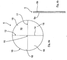
- Fig. 2a is shown, in which the branch duct 4 together with the rupture disk device 5 occluding this is arranged, for example, essentially centrally and / or centrally in the housing 25, so that the branch duct 4 is completely surrounded by a main flow duct 10.
- the branch channel 4 is here exemplarily annular along its entire longitudinal extension direction in the housing 25 surrounded by the arranged in the main flow channel exhaust gas purification element 3, in such a way that the branch channel 4 and the annular surrounding at least one exhaust gas purification element 3 or together the main flow channel 10 in a two housing portions 11, 12 are mutually separated common housing plane.
- the housing may have any arbitrary external geometry, for example, as shown, have a rectangular cross-section. However, it is of course also possible that the housing has a circular or cylindrical cross-section. Like also in the Fig. 2b indicated schematically, a plurality of different emission control elements 3 in the main flow channel 10, which surrounds the branch channel 4 may be arranged.
- the branch channel 4 and thus the rupture disc device closing this is arranged substantially in a rectilinear extension of a feed 27 of the exhaust gas into the housing 25 and a discharge 28 of the exhaust gas from the housing 25.
- This ensures that, for example, in conjunction with gas and dual-fuel engines as internal combustion engines, in an explosion in the exhaust system, the resulting pressure wave runs directly against the rupture disk device 5 and not against the arranged in the housing exhaust gas purification elements 3, whereby the latter be reliably protected against damage.
- a corresponding bursting pressure applied to the bursting disk device 5 the same breaks, so that then again, as in the embodiment according to Fig. 1 , At least a partial flow 7 can flow via the branch channel 4 (exhaust gas flow 8).
- the rupture disk device 5 closes in the mounted basic position an inflow-side mouth region of the branch channel 4, thereby ensuring that there is no undesirable turbulence and turbulence in the area in front of the rupture disk device 5.
- the rupture disk device 5 could also be located further downstream of the orifice opening thereof in the branching channel 4 (seen in the flow direction of the exhaust gas).
- branch duct 4 and the main flow duct 10 having the at least one exhaust gas purification element 3 again flow into a common housing region 11 downstream of the exhaust gas purification element 3, namely, as shown, in a direction to a discharge 28 of the exhaust gas from the housing 25 leading common housing portion 11 open.
- the housing wall portion of the housing 25 extending from the feeder 27 is initially funnel-shaped to direct the exhaust flow 6 in the desired manner toward the main flow passage 10.
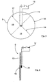
- FIG. 3 an embodiment of an exhaust system 1 according to the invention is shown, in which the branch channel 4 forms a parallel to a main flow channel 10 extending and substantially permeable by a partial flow 7 flow channel.
- One or more exhaust gas purification elements 3 are respectively arranged in the main flow channel 10 and in the branch channel 4, wherein the main flow channel side and the branch channel side exhaust gas purification element seen in the flow direction of the exhaust gas are spatially offset from each other such that the at least one branch channel side exhaust gas purification element 3 seen in the flow direction upstream of the at least one main flow channel side exhaust gas purification element 3 is located.
- the rupture disk device 5 is arranged here in a common wall region 29 of the main flow channel 10 and the branch channel 4 lying between the main flow channel side and branch channel side exhaust gas purification element 3.
- the inflowing exhaust gas stream 6 is divided immediately after the supply 27 to the main flow channel 10 and the branch channel 4, wherein the larger amount of exhaust gas flow through the main flow channel 10, because the upstream of the main flow channel side exhaust gas purification elements 3 upstream branch-side exhaust gas purification elements 3 here form a relatively high flow resistance, which causes just the larger amount of exhaust gas flows over the main flow channel 10.
- both the exhaust gas cleaning elements 3 arranged on the main flow channel side and the exhaust gas purification elements 3 located upstream thereto are correspondingly bypassed, so that the exhaust gas flow through the housing 25 can take place unhindered.
- the exhaust gas purification as in the Fig. 3 is shown schematically and dashed, optionally downstream of the rupture disk device 5 in the branch channel optionally at least one further emission control element 3 may be arranged.
- branch channel 4 and the main flow channel 10 thus open downstream of their respective exhaust gas purification elements 3 again in a common housing portion 11, which leads to a discharge 28 of the exhaust gas from the housing 25.
- the rupture disk device 5 can in principle be formed in different ways, such as by a conventional rupture disk or bursting disk, as for example in the DE 102 06 805 A1 is described.
- rupture disk device 5 A particularly preferred embodiment of the rupture disk device 5 will be described below in connection with FIGS Fig. 4 to 8 described in more detail:
- the rupture disk device 5 as in the Fig. 4a and 4b represented by a single bursting plate or rupture disk to be formed, which has here only by way of example a circular outer geometry, but just as well, as for example in connection with the Fig. 2a and 2b the case would be any other suitable geometry, for example a rectangular outer geometry.
- the rupture disk device formed by a single rupture disk here has predetermined breaking points 14, and although in the form of the bursting disk wall not penetrating notches.
- These predetermined breaking points 14 form a defined predetermined breaking point pattern 17, according to which a plurality of spaced apart and extending from a central rupture disk 15 radially outward to the rupture disk edge 16 toward extending predetermined breaking points 14 are provided, each forming a predetermined breaking point line.
- These predetermined breaking point lines are in the circumferential direction of the rupture disk in each case, for example, uniformly spaced from each other, so that each rupture disk areas lying between two predetermined breaking line forms a displaceable or pivotable bursting disk wall segment 18.
- the rupture disk device 5 can also be formed by two rupture disks 5a, 5b which lie adjacent one another, preferably in a planar abutment connection and which are optionally dimensioned differently or designed differently.
- This electrical heating element 13 is arranged here by way of example centrally or centrally on the rupture disk device 5 formed here by a single rupture disk and causes the associated rupture disk wall region to be heated in the activated state of the electrical heating element 13 and thereby in particular thermally damaged or destroyed.
- the rupture disk of the rupture disk device 5 may again have the predetermined breaking points described above, so that after an initial damage or destruction of the middle rupture disk region 15 by the electric heating element 13 by then applied relatively high exhaust backpressure targeted displacement of the flap-like bursting disk wall segments 18 and thus a controlled release of the branch line 4 for the exhaust gas flow can take place.
- the electric heating element 13 is here coupled to the control device 19, which is shown only by way of example, which then controls the electrical heating element 13 when, generally speaking, it has been determined by means of at least one sensor that the exhaust gas flow 8 is to be released via the branch line 4.
- the differential pressure can be measured.
- temperature and / or NOx sensors can be used or their measurement results can be used to control the activation of the electric heating element 13 as a rupture aid.
- FIG. 2 The previously to Fig. 2 The same applies analogously to the one side view of a rupture disk direction 5 formed by a single rupture disk Fig. 6 in which the central or central rupture disk area 15 is assigned a blasting element 20 with an explosive charge which destroys the assigned bursting disk wall area in the activated state by igniting the explosive charge.
- the rupture aid is shown by way of example and schematically only on one side of the rupture disk, this can of course also be arranged on the other side. A mutual arrangement is also possible, as well as an arrangement of the bursting aids at different locations of the rupture disk.
- FIG. 7 In the sake of clarity greatly exaggerated drawn representation of Fig. 7 an embodiment is shown, in which two spaced apart or substantially parallel rupture discs 5a, 5b form a rupture disk device 5, which have between them, a free space 21 forming gap gap.
- the free space 21 can be charged by means of a feed device 22 with a gaseous (for example compressed air) or liquid (for example water) working medium as a bursting aid, so that a bursting pressure acting on the bursting disk walls from the free space 21 and thus from inside can be established in the Fig. 7 is shown in dashed lines. From a defined bursting pressure then burst the rupture disc assembly of the two rupture discs 5a, 5b, so that then the branch line 4, for example the exhaust gas flow 8 is released. Again, the feeder 22 is in turn driven by the control device 19 accordingly.
- a gaseous for example compressed air
- liquid for example water
- shut-off element 23 can be shut off. This means that ultimately the shut-off element 23 is actuated by means of the control device in order to allow the supply of the working medium, for example compressed air, into the free space 21.
- the double-walled rupture disk arrangement 5 should be designed here so that the supplied working medium can inflate the rupture disks 5a, 5b in the manner shown.
- a defined predetermined predetermined breaking point pattern can be formed in each case.
- Fig. 7 In conjunction with the double-walled rupture disk arrangement of Fig. 7 can of course also be provided between the rupture disks 5a, 5b, for example, substantially centrally and centrally to include or arrange other Berst Anlagenn, for example, the electric heating element 13 or the blasting element 20th
- This construction with a double-walled rupture disc arrangement has the particular advantage that the supply lines or valves or all further required components of the respective rupture aid can not get in contact with the exhaust gas.
- FIG. 8 Another alternative embodiment is shown, in which the rupture disk device formed by a single rupture disk 5 is assigned a Druck Kunststoffzuclass Rhein 26 as a rupture aid, and preferably so that a mouth opening of the compressed air supply means 26 is directed substantially centrally of the rupture disk.
- the compressed air supply means 26 can then be suitably controlled (and in an analogous manner to the previous embodiments) of the control device 19 not shown here one or more compressed air pulses and / or shocks, preferably applied interval or pulse-like manner on the rupture disk and thus destroyed. It is understood that the compressed air supply means 26 can be shut off by means of a shut-off element 23.
Description
Die Erfindung betrifft eine Abgasanlage für Brennkraftmaschinen nach dem Oberbegriff des Anspruchs 1 bzw. ein Fahrzeug oder Wasserfahrzeug, insbesondere Schiff, nach Anspruch 13.The invention relates to an exhaust system for internal combustion engines according to the preamble of
Um die bei der Verbrennung von Kraftstoffen in Brennkraftmaschinen, beispielsweise Dieselmotoren, entstehenden Schadstoffe zu verringern, ist der Einsatz von Abgasreinigungs- bzw. Abgasnachbehandlungseinrichtungen in Form von Abgasreinigungselementen allgemein bekannt. Derartige Abgasreinigungselemente zur Nachbehandlung des Abgases können zum Beispiel Partikelfilter, SCR-Katalysatoren, etc. sein.In order to reduce the resulting in the combustion of fuels in internal combustion engines, such as diesel engines pollutants, the use of Abgasreinigungs- or exhaust aftertreatment devices in the form of exhaust gas purification elements is well known. Such exhaust gas purification elements for aftertreatment of the exhaust gas may be, for example, particulate filters, SCR catalysts, etc.
Immer strengere Abgasvorschriften machen mittlerweise auch bei in Schiffen eingesetzten Motoren eine Abgasnachbehandlung, zum Beispiel in Form von Partikelfiltern, SCR-Katalysatoren zur NOX-Reduzierung und DeSOx-Anlagen erforderlich.Increasingly stringent emission regulations mean that, even in the case of engines used in ships, exhaust after-treatment, for example in the form of particulate filters, SCR catalysts for NOX reduction and DeSOx systems, is now required.
Insbesondere bei relativ geringen Strömungsquerschnitten in den Abgasreinigungselementen, wie dies beispielsweise bei Schiffsmotoren der Fall ist, kann es gegebenenfalls zu einer Verstopfung dieser Abgasreinigungselemente kommen. Dies ist umso mehr der Fall, wenn die Brennkraftmaschine mit Kraftstoffen schlechter Qualität betrieben wird, was ebenfalls relativ häufig bei Schiffsmotoren der Fall ist, aber ebenso bei Brennkraftmaschinen von Fahrzeugen der Fall sein kann.In particular, at relatively low flow cross-sections in the exhaust gas purification elements, as is the case for example in marine engines, it may possibly lead to a clogging of these exhaust gas purification elements. This is all the more the case when the internal combustion engine is operated with poor quality fuels, which is also relatively common in marine engines, but may also be the case with internal combustion engines of vehicles.
Eine derartige fortschreitende Verstopfung eines Abgasreinigungselementes führt zu einem starken Anstieg des Abgasgegendrucks und hat eine eventuelle Motorschädigung zur Folge. Aus diesem Grund werden Bypassleitungen vorgesehen, mittels denen die Abgasreinigungselemente bei Bedarf überbrückt werden können. Dadurch wird somit auch im Störungsfall ein sicherer Betrieb der Brennkraftmaschine und damit der Betrieb eines Fahrzeuges bzw. die Manövrierbarkeit eines Schiffes sichergestellt.Such progressive clogging of an exhaust gas purification element leads to a strong increase of the exhaust gas back pressure and has a possible engine damage to the result. For this reason, bypass lines are provided by means of which the exhaust gas purification elements can be bridged if necessary. As a result, a safe operation of the internal combustion engine and thus the operation of a vehicle or the maneuverability of a ship is thus ensured even in case of failure.
Um die Bypassleitung zu öffnen, werden dabei üblicherweise Absperrvorrichtungen in Form von Abgasklappen oder Abgasschiebern verwendet. Allerdings besteht hier, aufgrund der Tatsache, dass sie nur sehr selten verwendet und zusätzlich permanent dem Abgas ausgesetzt sind, die Gefahr, dass sie sich festsetzen und nicht mehr geöffnet werden können. Zudem ist meist eine Luftspülung an den Wellendurchgängen der Abgasklappe vorzusehen, um einen Abgasaustritt in die Umgebung zu vermeiden. Dies führt zu einem relativ hohen apparativen Aufwand und zu hohen Investitions- und Betriebskosten, da permanent Druckluft zur Verfügung gestellt werden muss.In order to open the bypass line, usually shut-off devices in the form of exhaust valves or exhaust valves are used. However, due to the fact that they are used very rarely and are also permanently exposed to the exhaust gas, there is the danger that they may become stuck and can not be opened. In addition, an air purge is usually provided at the shaft passages of the exhaust valve in order to avoid exhaust gas leakage into the environment. This leads to a relatively high expenditure on equipment and high investment and operating costs, since permanent compressed air must be made available.
Desweiteren ist es aus der
Weiter ist aus der
Demgegenüber ist es Aufgabe der vorliegenden Erfindung, eine Abgasanlage für Brennkraftmaschinen zu schaffen, die die bedarfsweise Freigabe eines, einer Abgasreinigungseinrichtung zugeordneten Bypass- bzw. Abzweigkanals auf baulich einfache und kompakte Weise ermöglicht.In contrast, it is an object of the present invention to provide an exhaust system for internal combustion engines, which enables the need for release of a, an exhaust purification device associated bypass or branch channel in a structurally simple and compact manner.
Diese Aufgabe wird gelöst mit den Merkmalen der unabhängigen Patentansprüche. Vorteilhafte Ausgestaltungen hierzu sind Gegenstand der darauf rückbezogenen Unteransprüche.This object is achieved with the features of the independent claims. Advantageous embodiments thereof are the subject of the dependent claims.
Gemäß Anspruch 1 wird eine Abgasanlage für Brennkraftmaschinen vorgeschlagen, die eine Abgasleitung aufweist, in der wenigstens ein Abgasreinigungselement (zum Beispiel ein Partikelfilter, ein SCR-Katalysator und/oder eine DeSOx-Anlage, etc.) angeordnet ist. Ferner weist die Abgasleitung wenigstens einen parallel zu dem wenigstens einen Abgasreinigungselement angeordneten Abzweigkanal (zum Beispiel wenigstens einen stromauf des wenigstens einen oder stromauf wenigstens eines Abgasreinigungselementes abzweigenden Abzweigkanal) auf, in dem eine bei einem definierten Berstdruck berstende Berstscheibeneinrichtung angeordnet ist. Weiter ist vorgesehen, dass das wenigstens eine Abgasreinigungselement zusammen mit der Berstscheibeneinrichtung in einem Bestandteil der Abgasleitung bildenden gemeinsamen Gehäuse angeordnet sind, wobei die Berstscheibeneinrichtung dergestalt strömungstechnisch parallel zu dem wenigstens einen Abgasreinigungselement angeordnet ist, dass diese bei einem definierten Berstdruck birst und damit die Abgasströmung durch den und/oder zu dem Abzweigkanal freigegeben ist.According to
Erfindungsgemäß ist der Abzweigkanal durch die diesem zugeordnete Berstscheibeneinrichtung in der Grundstellung nicht vollständig verschlossen, sondern bildet der Abzweigkanal einen parallel zu wenigstens einem Hauptströmungskanal verlaufenden und von einer Abgasteilströmung durchströmbaren Strömungskanal aus. Bei dieser Ausführungsform ist bevorzugt sowohl in dem wenigstens einen Hauptströmungskanal als auch in dem Abzweigkanal jeweils wenigstens ein Abgasreinigungselement angeordnet, wobei die hauptströmungskanalseitigen und abzweigkanalseitigen Abgasreinigungselemente in dem Abzweigkanal in Strömungsrichtung dergestalt örtlich zueinander versetzt sind, dass das wenigstens eine abzweigkanalseitige Abgasreinigungselement in Strömungsrichtung gesehen stromauf des wenigstens einen hauptströmungskanalseitigen Abgasreinigungselementes liegt. Durch diese hintereinanderliegende, versetzte Anordnung der hauptströmungskanalseitigen und der abzweigkanalseitigen Abgasreinigungselemente ist sichergestellt, dass im Bereich des Abzweigkanals ein relativ hoher Abgasgegendruck für den einströmenden Abgasstrom vorherrscht, so dass ein Großteil der Abgasströmung über den Hauptströmungskanal strömt, während allenfalls ein Teilstrom über den Abzweigkanal und das dort angeordnete wenigstens eine Abgasreinigungselement strömt. Bei einem derartigen Aufbau ist dann die wenigstens eine Berstscheibeneinrichtung in einem, zwischen den hauptströmungskanalseitigen und abzweigkanalseitigen Abgasreinigungselementen liegenden gemeinsamen Wandbereich des wenigstens einen Hauptströmungskanals und des Abzweigkanals angeordnet, wobei die wenigstens eine Berstschreibeneinrichtung bei einem definierten Berstdruck birst und die Abgasströmung von dem wenigstens einen Hauptströmungskanal in den Abzweigkanal stromab des dortigen wenigstens einen Abgasreinigungselementes freigibt. Das heißt mit anderen Worten, dass durch die versetzte Anordnung der hauptströmungskanalseitigen und abzweigkanalseitigen Abgasreinigungselemente in Verbindung mit der zwischen diesen liegenden Berstscheibeneinrichtung sichergestellt ist, dass für den Fall, dass das wenigstens eine stromauf liegende Abgasreinigungselement des Hauptströmungskanals in einem solchen Maße verstopft sein sollte, dass sich im Hauptströmungskanal ein, einen bestimmten Druckschwellwert übersteigender Berstdruck aufbaut, die Berstscheibeneinrichtung zerstört wird und dann das Überströmen des hauptströmungskanalseitigen Abgasstroms in den dann als Bypass fungierenden Abzweigkanal ermöglicht wird, und zwar stromab des abzweigkanalsseitigen wenigstens einen Abgasreinigungselementes, um das ungehinderte Durchströmen der Abgasleitung mit dem Abgasstrom sicherzustellen.According to the branch channel is not completely closed by the rupture disc associated therewith in the basic position, but forms the branch channel extending parallel to at least one main flow channel and can be flowed through by a flow of exhaust gas flow channel. In this embodiment, at least one exhaust gas purification element is preferably arranged in each of the at least one main flow channel and in the branch channel, wherein the main flow channel side and branch channel side exhaust gas cleaning elements are offset locally in the branch channel in the flow direction such that the at least one branch channel side exhaust gas purification element upstream of the at least one main flow channel side exhaust gas purification element is located. Through this successive staggered arrangement of the main flow channel side and the branch channel side exhaust gas cleaning elements ensures that prevails in the region of the branch channel, a relatively high exhaust back pressure for the inflowing exhaust stream, so that a majority of the exhaust gas flow over the main flow channel, while possibly a partial flow through the branch channel and the arranged there at least one exhaust gas purification element flows. In such a construction, the at least one rupture disk device is then arranged in a common wall region of the at least one main flow channel and the branch channel lying between the main flow channel side and branch channel side exhaust gas cleaning elements, the at least one rupture writing device bursting at a defined rupture pressure and the exhaust flow from the at least one main flow channel the branch channel downstream of the local at least one Emission control element releases. In other words, the staggered arrangement of the main flow passage side and branch passage side exhaust gas purifying devices in conjunction with the rupture disc device therebetween ensures that if the at least one upstream exhaust purification element of the main flow passage should be clogged to such an extent in the main flow channel, builds up a certain pressure threshold bursting pressure, the rupture disk device is destroyed and then the overflow of the main flow channel side exhaust stream is then allowed to bypass the branch passage, namely downstream of the branch channel side at least one exhaust gas purification element to the unimpeded flow through the exhaust pipe with the Ensure exhaust flow.
Gegebenenfalls kann in Verbindung mit diesem Aufbau im Abzweigkanal stromab der Berstscheibeneinrichtung wenigstens ein weiteres Abgasreinigungselement angeordnet sein, wodurch dann auch die weitere Reinigung des Abgasstroms sichergestellt wäre.Optionally, in connection with this construction, at least one further exhaust-gas purification element may be arranged downstream of the rupture disk device in the branch-off conduit, whereby then also the further purification of the exhaust-gas flow would be ensured.
Insgesamt ergibt sich hierdurch eine insbesondere für beengte Einbauverhältnisse geeignete kompakte Bauform. Das Gehäuse kann hierbei integraler Bestandteil der Abgasleitung sein oder aber auch durch ein separates Bauteil gebildet sein, das in die Abgasleitung eingesetzt wird.Overall, this results in a particularly suitable for cramped installation conditions compact design. The housing may in this case be an integral part of the exhaust pipe or else be formed by a separate component which is inserted into the exhaust pipe.
Besonders bevorzugt münden der Abzweigkanal und wenigstens ein das wenigstens eine Abgasreinigungselement aufweisender Hauptströmungskanal stromab des wenigstens einen Abgasreinigungselementes in einen gemeinsamen Gehäusebereich ein, und zwar insbesondere in einen zur Abführung des Abgases aus dem Gehäuse führenden gemeinsamen Gehäusebereich ein. Damit ist sichergestellt, dass sich auch bei einer Abgasströmung über den Abzweigkanal die gewünschten Strömungsverhältnisse im Gehäuse einstellen, und zwar analog zu einer Abgasströmung über den Hauptströmungskanal, in dem das wenigstens eine Abgasreinigungselement angeordnet ist.Particularly preferably, the branch duct and at least one main flow duct having the at least one exhaust gas purification element lead into a common housing region downstream of the at least one exhaust gas purification element, specifically into a common housing region leading out of the housing for the exhaust gas. This ensures that even at a Exhaust flow via the branch channel to set the desired flow conditions in the housing, and analogous to an exhaust gas flow over the main flow channel, in which the at least one exhaust gas purification element is arranged.
Insgesamt ist somit eine Ausführungsform bevorzugt, bei der der Abzweigkanal und der wenigstens eine Hauptströmungskanal stromab ihrer jeweiligen Abgasreinigungselemente in einen gemeinsamen Gehäusebereich einmünden, und zwar insbesondere in einen zu einer Abführung aus dem Gehäuse führenden gemeinsamen Gehäusebereich einmünden. Dies bewirkt eine kompakte Bauweise.Overall, therefore, an embodiment is preferred in which the branch channel and the at least one main flow channel open downstream of their respective exhaust gas cleaning elements in a common housing area, and in particular open into a leading to a discharge from the housing common housing area. This causes a compact design.
Desweiteren kann der, die wenigstens eine Berstscheibeneinrichtung aufweisende Wandbereich wenigstens im Bereich der Berstscheibeneinrichtung winklig bezüglich der Strömungsrichtung ausgerichtet sein, und zwar insbesondere winklig gegen das stromauf liegende wenigstens eine Abgasreinigungselement angestellt sein. Mit einer derartigen winkligen Ausrichtung ist sichergestellt, dass eine ausreichende Berstkraft bei einem Abgasstau stromauf des wenigstens einen hauptströmungskanalseitigen Abgasreinigungselementes auf die Berstscheibeneinrichtung wirkt.Furthermore, the wall region having at least one rupture disk device can be aligned at an angle with respect to the flow direction, at least in the area of the rupture disk device, and in particular at an angle to the upstream at least one exhaust gas cleaning element. With such an angular orientation it is ensured that a sufficient bursting force acts on the rupture disk device upstream of the at least one main flow channel-side exhaust gas purification element in the case of an exhaust gas flow.
Die Berstscheibeneinrichtung selbst kann auf unterschiedlichste Art und Weise ausgebildet sein, so zum Beispiel durch eine einfache, herkömmliche Berstscheibe gebildet sein. Um das Bersten der Berstscheibeneinrichtung noch besser kontrollieren zu können und ein evtl. unerwünschtes Bersten bei einem betriebsbedingt erwünschten Anstieg des Abgasgegendrucks zuverlässig zu vermeiden, kann die Berstscheibeneinrichtung aber durch wenigstens zwei in Strömungsrichtung hintereinander angeordnete, insbesondere in einer flächigen Anlageverbindung aneinanderliegende, Berstscheiben gebildet sein.The rupture disk device itself can be designed in many different ways, for example, be formed by a simple, conventional rupture disk. In order to be able to control the rupture of the rupture disk device even better and to reliably avoid any undesirable bursting in the event of an operationally desired increase in the exhaust counterpressure, the rupture disk device can be formed by at least two rupture disks arranged one behind the other in the flow direction, in particular abutting one another in a planar contact connection.
Im Falle mehrerer Berstscheiben können diese, wie soeben erwähnt, grundsätzlich in einer flächigen Anlageverbindung aneinander anliegen. Gegebenenfalls können diese aber auch einen definiert vorgegebenen Spaltabstand voneinander aufweisen.In the case of multiple rupture discs, these may, as just mentioned, in principle abut each other in a planar abutment connection. Optionally, these can also have a defined predetermined gap distance from each other.
Eine besonders zuverlässige und funktionssichere Aktivierung der Berstscheibeneinrichtung ist dann gegeben, wenn der Berstscheibeneinrichtung eine mittels einer Steuereinrichtung in Abhängigkeit von wenigstens einem definiert vorgegebenen Parameter, insbesondere in Abhängigkeit von einem Erreichen oder Überschreiten eines definiert vorgegebenen Schwellwertes, ansteuerbare und aktivierbare Bersthilfe zugeordnet ist. Diese Bersthilfe kann durch wenigstens ein Heizelement, insbesondere wenigstens ein elektrisches Heizelement, und/oder durch wenigstens ein Sprengelement und/oder durch ein gasförmiges oder flüssiges Arbeitsmedium gebildet sein, mittels dem oder mittels denen die wenigstens eine Berstscheibe zur Freigabe der Abgasströmung durch den und/oder zu dem Abzweigkanal schwächbar und/oder zerstörbar ist.A particularly reliable and functionally reliable activation of the rupture disk device is provided when the rupture disk device is assigned a controllable and activatable rupture aid by means of a control device as a function of at least one defined parameter, in particular depending on reaching or exceeding a defined predetermined threshold value. This rupture aid can be formed by at least one heating element, in particular at least one electric heating element, and / or by at least one explosive element and / or by a gaseous or liquid working medium, by means of which or by which the at least one rupture disk for releasing the exhaust gas flow through the and / or weakenable and / or destructible to the branch channel.
Mit einer derartigen Bersthilfe kann somit die wenigstens eine Berstscheibe der Berstscheibeneinrichtung zum genau gewünschten Zeitpunkt auf kontrollierte Weise zerstört werden und damit zum geeigneten Zeitpunkt die Abgasströmung über bzw. zum Abzweigkanal freigegeben werden. Dies hilft wesentlich, die Betriebssicherheit der Abgasanlage im Hinblick auf die Abgasströmung durch den Abzweigkanal zu erhöhen.With such a rupture aid, the at least one rupture disk of the rupture disk device can thus be destroyed in a controlled manner at the exact desired time and thus the exhaust gas flow can be released via or to the branch duct at the appropriate time. This helps significantly to increase the reliability of the exhaust system with respect to the flow of exhaust gas through the branch channel.
Um die Bersthilfe zum geeigneten Zeitpunkt anzusteuern bzw. zu aktivieren, ist bevorzugt wenigstens ein Sensor stromauf und/oder stromab des wenigstens einen Abgasreinigungselementes im wenigstens einen Hauptströmungskanal angeordnet, mittels dem der wenigstens eine Parameter erfassbar ist, in Abhängigkeit von dem die Bersthilfe ansteuerbar und aktivierbar ist. Beispielsweise kann die Bersthilfe in Abhängig von einer mittels mehrerer Sensoren erfolgten Messung des Abgasgegendrucks über ein Abgasreinigungselement aktiviert werden, um sicherzustellen, dass die Berstscheibe genau dann zum Bersten gebracht wird, wenn dies erforderlich ist. Selbstverständlich kann die Aktivierung der Berstscheibe aber auch in Abhängigkeit von anderen Abgasparametern erfolgen, zum Beispiel in Abhängigkeit einer Abgastemperatur und/oder einer Stoffkonzentration im Abgas, um nur einige weitere Beispiele zu nennen.In order to actuate or activate the bursting aid at the appropriate time, preferably at least one sensor is arranged upstream and / or downstream of the at least one exhaust gas purification element in the at least one main flow channel, by means of which the at least one parameter can be detected, as a function of which the rupture aid can be activated and activated is. For example, the Bersthilfe depending on one by means of several Sensors were made to measure exhaust backpressure via an exhaust gas purifier to ensure that the rupture disc is ruptured at the exact moment it is needed. Of course, the activation of the rupture disk can also be carried out as a function of other exhaust gas parameters, for example as a function of an exhaust gas temperature and / or a substance concentration in the exhaust gas, to name just a few further examples.
Gemäß einer ersten bevorzugten konkreten Ausgestaltung ist die Besthilfe durch wenigstens ein elektrisches Heizelement gebildet, das an einer definierten Stelle der Berstscheibe, insbesondere zentral oder mittig, angeordnet ist und das den zugeordneten Berstscheibenwandbereich im aktivierten Zustand erhitzt, insbesondere thermisch zerstört. Mit einem derartigen elektrischen Heizelement wird eine besonders zuverlässige und funktionssichere Bersthilfe zur Verfügung gestellt.According to a first preferred specific embodiment, the Besthilfe is formed by at least one electric heating element, which is arranged at a defined location of the rupture disk, in particular centrally or centrally, and which heats the associated bursting disk wall area in the activated state, in particular thermally destroyed. With such an electric heating element, a particularly reliable and reliable rupture aid is provided.
Die Bersthilfe kann aber auch durch wenigstens ein Sprengelement gebildet sein, das an einer definierten Stelle der Berstscheibe, insbesondere zentral und/oder mittig, angeordnet ist, und das den zugeordneten Berstscheibenwandbereich im aktivierten Zustand durch Zünden einer Sprengladung zerstört. Auch hier wird eine sehr hohe Funktionssicherheit bei Betätigung der Bersthilfe erzielt, die eine zuverlässige Zerstörung der Berstscheibe bewirkt.The bursting aid can also be formed by at least one blasting element, which is arranged at a defined location of the rupture disk, in particular centrally and / or centrally, and destroys the associated bursting disk wall area in the activated state by igniting an explosive charge. Again, a very high level of functional reliability is achieved upon actuation of the rupture aid, which causes a reliable destruction of the rupture disk.
Gemäß einer weiteren Ausführungsform kann die Berstscheibe wenigstens bereichsweise doppelwandig ausgebildet sein und einen zwischen gegenüberliegenden Wandbereichen liegenden Freiraum aufweisen, wobei der Freiraum mittels einer Zuführeinrichtung dergestalt mit dem gasförmigen oder flüssigen Arbeitsmedium beschickbar ist, dass ein vom Freiraum und damit von Innen her auf die Berstscheibenwände wirkender Berstdruck aufbaubar ist. Besonders bevorzugt sind hier zwei voneinander beabstandete und/oder im Wesentlichen parallel zueinander ausgerichtete Berstscheiben vorgesehen, die zwischen sich einen, den Freiraum ausbildenden Spaltabstand aufweisen.According to a further embodiment, the rupture disk may at least partially be double-walled and have a space lying between opposite wall space, wherein the free space by means of a feeder such with the gaseous or liquid working medium is chargeable that acting from the free space and thus from the inside on the bursting disk walls Bursting pressure is buildable. Particularly preferred here are two spaced apart and / or im Provided substantially parallel rupture discs, which have between them, the free space forming gap distance.
Gemäß einer weiteren alternativen Ausführungsform ist der Berstscheibe eine Druckluftzuführeinrichtung als Bersthilfe zugeordnet, und zwar bevorzugt dergestalt, dass eine Mündungsöffnung der Druckluftzuführeinrichtung im Wesentlichen mittig auf die Berstscheibe gerichtet ist. Mittels einer derartigen Druckluftzuführeinrichtung kann eine definiert vorgegebene Anzahl von Druckluftimpulsen und/oder -stößen, vorzugsweise intervall- oder pulsartig, gesteuert auf einen definierten Bereich der Berstscheibe aufgebracht werden. Bei dieser Ausführungsform handelt es sich bevorzugt um eine einwandige bzw. einlagige Berstscheibenausgestaltung. Anstelle Druckluft kann bei dieser Ausführungsvariante selbstverständlich auch jedwedes andere geeignete gasförmige bzw. ausdrücklich auch flüssige Medium Verwendung finden. Die Begrifflichkeit Druckluft ist hier somit ausdrücklich in einem weiten und nicht auf Druckluft als solche beschränkten Sinne zu verstehen.According to a further alternative embodiment, the rupture disk is assigned a compressed air supply device as a rupture aid, preferably in such a way that an orifice opening of the compressed air supply device is directed substantially centrally onto the rupture disk. By means of such a compressed air supply device, a defined predetermined number of compressed air pulses and / or pulses, preferably in an interval or pulse-like manner, can be applied to a defined region of the rupture disk in a controlled manner. In this embodiment, it is preferably a single-wall or bursting disc design. Instead of compressed air can of course be used in this embodiment, any other suitable gaseous or expressly liquid medium use. The term compressed air here is thus to be understood in a broad and not limited to compressed air as such meaning.
Gemäß einer weiteren alternativen Ausführungsform ist im Abgastrakt der Brennkraftmaschine wenigstens eine Explosionsdruckerfassungseinrichtung, insbesondere wenigstens ein Drucksensor oder wenigstens ein Mikrofon, angeordnet, mittels der eine Explosion und damit ein plötzlicher Druckanstieg detektierbar ist. Die Explosionsdruckerfassungseinrichtung ist mit einer Steuereinrichtung gekoppelt, mittels der bei einer Explosionsdetektion eine Bersthilfe dergestalt ansteuerbar ist, dass mittels der Bersthilfe die wenigstens eine Berstscheibeneinrichtung vor dem Erreichen der Berstscheibeneinrichtung durch die Druckwelle zerstört wird. Die Zerstörung der Berstscheibenrichtung kann dabei grundsätzlich wie vorstehend beschrieben erfolgen, also zum Beispiel durch ein elektrisches Heizelement, durch eine Sprengladung, durch einen Druckluftimpuls, etc..According to a further alternative embodiment, at least one explosion pressure detection device, in particular at least one pressure sensor or at least one microphone, is arranged in the exhaust tract of the internal combustion engine, by means of which an explosion and thus a sudden increase in pressure can be detected. The explosion pressure detection device is coupled to a control device, by means of which a bursting aid can be triggered in an explosion detection in such a way that the at least one bursting disk device is destroyed by the pressure wave before the bursting disk device is reached by means of the bursting aid. The destruction of the bursting disc direction can basically be as described above, that is, for example, by an electric heating element, by an explosive charge, by a compressed air pulse, etc ..
Besonders bevorzugt ist eine konkrete Ausgestaltung, bei der das Gehäuse und das wenigstens eine Abgasreinigungselement so ausgelegt sind, dass diese einem Druckanstieg von wenigstens 300 mbar, bevorzugt von wenigstens 400 mbar und höchst bevorzugt von wenigstens 480 mbar standhalten. Damit ist sichergestellt, dass auch bei einem durch eine Druckwelle bzw. eine Explosion im Abgastrakt bewirkten Druckanstieg keine Beschädigung des Gehäuses bzw. des wenigstens einen Abgasreinigungselementes erfolgt.Particularly preferred is a specific embodiment in which the housing and the at least one exhaust gas cleaning element are designed so that they withstand a pressure increase of at least 300 mbar, preferably of at least 400 mbar and most preferably of at least 480 mbar. This ensures that even with a pressure increase caused by a pressure wave or an explosion in the exhaust tract no damage to the housing or of the at least one exhaust gas purification element takes place.
Zusätzlich oder aber auch alternativ zu einer derartigen Bersthilfe kann die wenigstens eine Berstscheibe oder im Falle mehrerer Berstscheiben wenigstens eine der Berstscheiben, insbesondere wenigstens die stromauf liegende Berstscheibe, wenigstens eine definierte Sollbruchstelle aufweisen. Mit derartigen Sollbruchstellen ist eine individuelle Anpassung und Auslegung der Berstscheibe an bzw. für den jeweiligen Einsatzfall möglich. Zudem können mit derartigen Sollbruchstellen genau diejenigen Bereiche festgelegt und definiert werden, an denen die Berstscheibe letztendlich bersten soll.In addition or as an alternative to such a bursting aid, the at least one bursting disk or, in the case of a plurality of bursting disks, at least one of the bursting disks, in particular at least the upstream bursting disk, can have at least one defined predetermined breaking point. With such predetermined breaking points, an individual adaptation and design of the rupture disk on or for the particular application is possible. In addition, with such predetermined breaking points exactly those areas can be defined and defined, at which the rupture disk should ultimately burst.
Insbesondere in Verbindung mit der Sicherstellung einer Gasdichtheit bei der Anordnung einer einzigen Berstscheibe ist es von Vorteil, wenn die wenigstens eine Sollbruchstelle durch eine, die Berstscheibenwand nicht durchdringende Kerbe gebildet ist. Bevorzugt ist in diesem Fall zudem eine Ausgestaltung, bei der eine Sollbruchstelle aufweisende Berstscheibe mehrere Kerben aufweist, die ein definiert vorgegebene Sollbruchstellenmuster ausbilden. Damit ist es möglich, die Berstscheibe in einer gewünschten Weise aufreißen bzw. aufplatzen zu lassen.In particular, in connection with ensuring a gas tightness in the arrangement of a single rupture disk, it is advantageous if the at least one predetermined breaking point is formed by a not penetrating the rupture disk notch. Also preferred in this case is an embodiment in which a rupture disk having a predetermined breaking point has a plurality of notches, which form a defined predetermined predetermined breaking point pattern. This makes it possible to rupture or burst open the rupture disc in a desired manner.
Das Sollbruchstellenmuster kann grundsätzlich auf unterschiedliche Art und Weise ausgebildet sein. Besonders bevorzugt ist jedoch ein Aufbau, bei dem mehrere voneinander beabstandete und sich von einem mittleren Berstscheibenbereich ausgehend nach radial außen zum Berstscheibenrand hin erstreckende Sollbruchstellen vorgesehen sein, die eine Sollbruchstellenlinie ausbilden. Wenigstens zwei derartiger Sollbruchstellenlinien können dann in Umfangsrichtung der Berstscheibe dergestalt voneinander beabstandet sein, dass die zwischen zwei Sollbruchstellenlinien liegenden Berstscheibenbereiche ein verlagerbares, insbesondere verschwenkbares, Berstscheibenwandsegment ausbilden. Diese Berstscheibenwandsegmente bilden dann nach dem Bersten regelmäßig Lappen aus, die sehr gut und kontrolliert verlagert bzw. verschwenkt werden können zur definierten Freigabe der Abgasströme durch den bzw. zum Abzweigkanal.The predetermined breaking point pattern can basically be designed in different ways. However, particularly preferred is a structure in which a plurality of spaced apart and starting from a middle rupture disk area radially outward to the rupture disk edge outwardly extending predetermined breaking points, which form a predetermined breaking point line. At least two such predetermined breaking line locations can then be spaced apart in the circumferential direction of the rupture disk such that the rupture disk regions lying between two predetermined breaking line lines form a displaceable, in particular pivotable, rupture disk wall segment. These rupture disk wall segments then regularly form rags after bursting, which can be displaced or pivoted very well and in a controlled manner for the defined release of the exhaust gas streams through or to the branch duct.
Die Bersthilfe kann desweiteren grundsätzlich auch zwischen zwei benachbarten und bevorzugt im Wesentlichen flächig aneinander anliegenden Berstscheiben aufgenommen und/oder angeordnet sein, was den Vorteil hat, dass die Bersthilfe durch die beiden Berstscheiben vom heißen und korrosiven Abgas abgetrennt und damit geschützt ist. Hierdurch können wesentlich kostengünstigere Materialien für diese Komponenten eingesetzt werden. Dies gilt sowohl für eine Sprengladung als auch ein elektrisches Heizelement als auch für die bereits beschriebene Zuführung eines Fluids, insbesondere Druckluft oder Wasser als fluides Medium, zwischen zwei benachbarte Berstscheiben.Furthermore, the rupture aid can in principle also be accommodated and / or arranged between two rupture disks which adjoin one another and preferably lie essentially flat, which has the advantage that the rupture aid is separated from the hot and corrosive exhaust gas by the two rupture disks and thus protected. As a result, much cheaper materials for these components can be used. This applies to both an explosive charge and an electric heating element as well as for the already described supply of a fluid, in particular compressed air or water as a fluid medium, between two adjacent rupture discs.
Desweiteren wird ein Fahrzeug oder Schiff mit einer Brennkraftmaschine in einer Abgasanlage beansprucht, wie sie zuvor bereits ausführlich gewürdigt worden ist.Furthermore, a vehicle or ship is claimed with an internal combustion engine in an exhaust system, as has already been extensively appreciated before.
Die Erfindung wird nachfolgend anhand einer Zeichnung näher erläutert.The invention will be explained in more detail with reference to a drawing.
Es zeigen:
- Fig. 1
- schematisch und beispielhaft einen Ausschnitt einer nichterfindungsgemäßen Abgasanlage einer Brennkraftmaschine mit einem in eine Abgasleitung eingesetzten Gehäuse, in dem sowohl die Berstscheibeneinrichtung als auch das wenigstens eine Abgasreinigungselement aufgenommen ist,
- Fig. 2a
- eine zur Ausführungsform gemäß
Fig. 1 alternative nichterfindungsgemäße Ausgestaltung des abgasleitungsseitig eingesetzten Gehäuses, - Fig. 2b
- eine schematische perspektivische Draufsicht auf das Gehäuse der
Fig. 2a , - Fig. 3
- eine erfindungsgemäße Ausführungsvariante eines in eine Abgasleitung einsetzbaren oder eingesetzten Gehäuses,
- Fig. 4a
- beispielhaft eine Ausführungsform einer Berstscheibeeinrichtung in einer Vorderansicht,
- Fig. 4b
- die Berstscheibeneinrichtung der
Fig. 4a in einer Seitenansicht (optional als doppelwandige Berstscheibeneinrichtung ausgebildet), - Fig. 5
- schematisch eine Berstscheibe mit einem elektrischen Heizelement als Bersthilfe,
- Fig. 6
- schematisch eine Seitenansicht einer Berstscheibe mit einem Sprengelement als Bersthilfe,
- Fig. 7
- schematisch eine doppelwandige Berstscheibenanordnung mit einem, mit einem gasförmigen oder flüssigen Arbeitsmedium als Bersthilfe beschickbaren Freiraum,
- Fig. 8
- schematisch eine Berstscheibe mit zugeordneter Druckluftzufuhreinrichtung als Bersthilfe.
- Fig. 1
- schematically and by way of example a detail of a non-inventive exhaust system of an internal combustion engine with a housing inserted into an exhaust pipe, in which both the rupture disk device and the at least one exhaust gas purification element is accommodated,
- Fig. 2a
- one to the embodiment according to
Fig. 1 alternative non-inventive embodiment of the exhaust gas line side housing used - Fig. 2b
- a schematic perspective top view of the housing of
Fig. 2a . - Fig. 3
- an embodiment according to the invention of an insertable or inserted into an exhaust pipe housing,
- Fig. 4a
- an example embodiment of a rupture disk device in a front view,
- Fig. 4b
- the rupture disk device of
Fig. 4a in a side view (optionally designed as a double-wall rupture disk device), - Fig. 5
- schematically a rupture disc with an electric heating element as a rupture aid,
- Fig. 6
- schematically a side view of a rupture disk with a sprinkler as a rupture aid,
- Fig. 7
- 1 schematically shows a double-walled rupture disk arrangement with a free space which can be charged with a gaseous or liquid working medium as a bursting aid,
- Fig. 8
- schematically a bursting disc with associated compressed air supply device as a rupture aid.
In der
Besonders bevorzugt ist jedoch eine Ausgestaltung, wie sie in der
Wie dies aus der
Wie dies insbesondere auch aus der
Ein weiterer besonderer Vorteil des Aufbaus gemäß der
Wie in der
Bei einem derartigen Aufbau wird sichergestellt, dass der Abzweigkanal 4 und der das wenigstens eine Abgasreinigungselement 3 aufweisende Hauptströmungskanal 10 stromab des Abgasreinigungselementes 3 wieder in einen gemeinsamen Gehäusebereich 11 einmünden, und zwar, wie dargestellt, in einem zu einer Abführung 28 des Abgases aus dem Gehäuse 25 führenden gemeinsamen Gehäusebereich 11 einmünden.In such a structure, it is ensured that the
Wie weiter dargestellt, ist der von der Zuführung 27 ausgehende Gehäusewandbereich des Gehäuses 25 anfänglich trichterförmig ausgebildet, um den Abgasstrom 6 in der gewünschten Weise in Richtung zu dem Hauptströmungskanal 10 zu lenken.As further shown, the housing wall portion of the
In der
Sowohl in dem Hauptströmungskanal 10 als auch in dem Abzweigkanal 4 sind jeweils ein oder mehrere Abgasreinigungselemente 3 angeordnet, wobei die hauptströmungskanalseitigen und die abzweigkanalseitigen Abgasreinigungselement in Strömungsrichtung des Abgases gesehen dergestalt örtlich zueinander versetzt sind, dass das wenigstens eine abzweigkanalseitige Abgasreinigungselement 3 in Strömungsrichtung gesehen stromauf des wenigstens einen hauptströmungskanalseitigen Abgasreinigungselementes 3 liegt.One or more exhaust
Die Berstscheibeneinrichtung 5 ist hier in einem, zwischen den hauptströmungskanalseitigen und abzweigkanalseitigen Abgasreinigungselement 3 liegenden gemeinsamen Wandbereich 29 des Hauptströmungskanals 10 und des Abzweigkanals 4 angeordnet.The
Bei einem derartigen Aufbau wird der einströmende Abgasstrom 6 unmittelbar nach der Zuführung 27 auf den Hauptströmungskanal 10 und den Abzweigkanal 4 aufgeteilt, wobei die größere Menge des Abgasstroms durch den Hauptströmungskanal 10 strömt, weil die gegenüber den hauptströmungskanalseitigen Abgasreinigungselementen 3 stromauf angeordneten abzweigkanalseitigen Abgasreinigungselemente 3 hier sofort einen relativ hohen Strömungswiderstand ausbilden, der bewirkt, dass eben die größere Menge an Abgas über den Hauptströmungskanal 10 strömt.In such a structure, the inflowing
Für den Fall dass sich dann, zum Beispiel durch das Zusetzen der hauptströmungskanalseitigen Abgasreinigungselemente 3 ein entsprechend Abgasgegendruck im Bereich stromauf des oder der hauptströmungskanalseitigen Abgasreinigungselemente(s) 3 ausbilden sollte, zum Beispiel durch Verstopfung des Abgasreinigungselementes 3 im Hauptströmungskanal 10, wirkt auf den winklig bezüglich des wenigstens einen hauptströmungskanalseitigen Abgasreinigungselementes 3 angestellten Wandbereich 29 bzw. die dort angeordnete Berstscheibeneinrichtung 5 ein hier durch die Pfeile 30 dargestellter Berstdruck. Übersteigt dieser Berstdruck einen definiert vorgegebenen Schwellwert, birst die Berstscheibeneinrichtung 5 und die Abgasströmung 8 vom Hauptströmungskanal 10 zum Abzweigkanal 4 ist freigegeben. Wie dies aus der
Auch bei dieser Ausführungsform münden der Abzweigkanal 4 und der Hauptströmungskanal 10 somit stromab ihrer jeweiligen Abgasreinigungselemente 3 wieder in einen gemeinsamen Gehäusebereich 11 ein, der zu einer Abführung 28 des Abgases aus dem Gehäuse 25 führt.Also in this embodiment, the
Die Berstscheibeneinrichtung 5 kann grundsätzlich auf unterschiedliche Art und Weise ausgebildet werden, so zum Beispiel durch eine herkömmliche Berstscheibe bzw. Berstplatte, wie sie zum Beispiel in der
Eine besonders bevorzugte Ausführungsform der Berstscheibeneinrichtung 5 wird nachfolgend in Verbindung mit den
Gemäß einer besonders einfachen und bevorzugten Ausführung kann die Berstscheibeneinrichtung 5, wie in den
Wie dies weiter aus der
Grundsätzlich wäre es ausreichend, lediglich Berstscheibeneinrichtungen 5 mit einer derartigen Sollbruchstellenkontur für ein definiertes Aufplatzen der Berstscheibeneinrichtung 5 einzusetzen. Für eine besonders kontrollierte Zerstörung der Berstscheibeneinrichtung 5 ist jedoch eine Ausführungsform vorteilhaft, bei der die Berstscheibeneinrichtung 5 mittels einer Bersthilfe kontrolliert und definiert zum Bersten gebracht wird.In principle, it would be sufficient to use only bursting
Hierzu kann in der Abgasanlage 1, wie dies lediglich beispielhaft in Verbindung mit der Ausführungsform gemäß
Auch hier kann die Berstscheibe der Berstscheibeneinrichtung 5 wiederum die zuvor beschriebenen Sollbruchstellen aufweisen, so dass nach einer anfänglichen Schädigung bzw. Zerstörung des mittleren Berstscheibenbereichs 15 durch das elektrische Heizelement 13 durch den dann weiter anliegenden relativ hohen Abgasgegendruck eine gezielte Verlagerung der lappenartigen Berstscheibenwandsegmente 18 und damit eine kontrollierte Freigabe der Abzweigleitung 4 für den Abgasstrom erfolgen kann.Again, the rupture disk of the
Das elektrische Heizelement 13 ist hier mit der lediglich beispielhaft dargestellten Steuereinrichtung 19 gekoppelt, die das elektrische Heizelement 13 dann ansteuert, wenn, ganz allgemein gesprochen, mittels wenigstens eines Sensors festgestellt worden ist, dass die Abgasströmung 8 über die Abzweigleitung 4 freizugeben ist. Mittels der Sensoren 9a, 9b kann, wie zuvor dargestellt, zum Beispiel der Differenzdruck gemessen werden. Alternativ oder zusätzlich können aber selbstverständlich auch Temperatur- und/oder NOx-Sensoren verwendet bzw. deren Messergebnisse herangezogen werden, um die Aktivierung des elektrischen Heizelementes 13 als Bersthilfe zu steuern.The
Anstelle der Anordnung von zwei Sensoren 9a, 9b kann somit grundsätzlich auch nur ein Sensor stromauf oder stromab des Abgasreinigungselementes 3 vorgesehen sein.Instead of the arrangement of two
Das zuvor zur
Auch wenn bei den Ausführungsformen der
In der aus Übersichtlichkeitsgründen stark übertrieben gezeichneten Darstellung der
Es versteht sich, dass die Zuführeinrichtung 22 mittels eines Absperrelementes 23 absperrbar ist. Das heißt, dass mittels der Steuereinrichtung letztendlich das Absperrelement 23 angesteuert wird, um die Zuführung des Arbeitsmediums, zum Beispiel Druckluft, in den Freiraum 21 hinein zu ermöglichen.It is understood that the
Es versteht sich weiter, dass die doppelwandige Berstscheibeanordnung 5 hier so ausgeführt sein soll, dass das zugeführte Arbeitsmedium die Berstscheiben 5a, 5b in der gezeigten Art und Weise aufblähen kann. Das heißt, dass der Anschluss der Zuführeinrichtung 22 entsprechend dicht auszuführen ist und dass die Berstscheiben 5 zum Beispiel randseitig dicht miteinander verbunden sein müssen, wie dies lediglich beispielhaft mittels der Verbindung 24 in der
Desweiteren kann selbstverständlich auch sowohl bei der Ausführungsform gemäß der
In Verbindung mit der doppelwandigen Berstscheibenanordnung der
Dieser Aufbau mit einer doppelwandigen Berstscheibenanordnung hat insbesondere den Vorteil, dass die Zuführleitungen bzw. Ventile bzw. alle weiter benötigten Bauteile der jeweiligen Bersthilfe nicht mit dem Abgas in Kontakt gelangen können.This construction with a double-walled rupture disc arrangement has the particular advantage that the supply lines or valves or all further required components of the respective rupture aid can not get in contact with the exhaust gas.
In der
Claims (13)
- Exhaust system for internal combustion engines, having an exhaust gas line (2) in which at least one exhaust gas purification element (3) is arranged, and having at least one branch duct (4) which is arranged parallel to the at least one exhaust gas purification element (3) and in which a bursting disc device (5) which bursts at a defined bursting pressure is arranged, wherein the at least one exhaust gas purification element (3) is arranged, together with the bursting disc device (5), in a common housing (25) forming part of the exhaust gas line (2), and wherein the bursting disc device (5) is arranged fluidically parallel to the at least one exhaust gas purification element (3) in such a way that said bursting disc device (5) bursts at a defined bursting pressure and therefore releases the exhaust gas flow through the and/or to the branch duct (4), characterized
in that the branch duct (4) forms a flow duct which runs parallel to at least one main flow duct (10) and through which a partial flow of exhaust gas can flow,
in that at least one exhaust gas purification element (3) is arranged respectively both in the at least one main flow duct (10) and in the branch duct (4), wherein the exhaust gas purification elements (3) on the main flow duct side and on the branch duct side are positionally offset with respect to one another in the direction of flow in such a way that the at least one exhaust gas purification element (3) on the branch duct side lies, when viewed in the direction of flow, upstream of the at least one main flow duct side exhaust gas purification element (3),
in that the at least one bursting disc device (5) is arranged in a common wall region (29), lying between the main flow duct side and branch duct side exhaust gas purification elements (3), of the at least one main flow duct (10) and of the branch duct (4), wherein the at least one bursting disc device (5) bursts at a defined bursting pressure and releases the exhaust gas flow from the at least one main flow duct into the branch duct (4) downstream of the at least one exhaust gas purification element (3) there. - Exhaust system according to Claim 1, characterized in that at least one further exhaust gas purification element (3) is arranged downstream of the bursting disc device (5) in the branch duct (4).
- Exhaust system according to Claim 1 or 2, characterized in that the branch duct (4) and at least one main flow duct (10) having the at least one exhaust gas purification element (3) open, downstream of the at least one exhaust gas purification element (3), into a common housing region, in particular into a common housing region (11) which leads to a discharge line (28) of the exhaust gas from the housing (25).
- Exhaust system according to one of the preceding claims, characterized in that the wall region having the at least one bursting disc device (5) is oriented, at least in the region of the bursting disc device (5), at an angle with respect to the direction of flow, in particular is positioned at an angle with respect to the at least one upstream exhaust gas purification element (3).
- Exhaust system according to one of the preceding claims, characterized in that the bursting disc device (5) is formed by at least one bursting disc, in particular the bursting disc device (5) is formed by at least two bursting discs which are arranged one behind the other in the direction of flow (9) and bear, in particular, in a planar abutting connection.
- Exhaust system according to one of the preceding claims, characterized in that a bursting aid which can be actuated and activated by means of a control device (12) as a function of at least one parameter which is prescribed in a defined fashion, in particular as a function of a threshold value which is prescribed in a defined fashion being reached or exceeded is assigned to the bursting disc device (5), wherein there is preferably provision that the bursting aid is formed by at least one heating element (13) and/or by at least one explosive element (20) and/or by a gaseous or liquid working medium by means of which the at least one bursting disc of the bursting disc device (5) can be weakened and/or destroyed in order to release the flow of exhaust gas through and/or to the branch duct (4).
- Exhaust system according to Claim 6, characterized in that at least one sensor (10, 11) is arranged upstream and/or downstream of the at least one exhaust gas purification element (3), by means of which sensor (10, 11) the at least one parameter can be detected, as a function of which the bursting aid can be actuated and activated.
- Exhaust system according to Claim 6 or 7, characterized in that the bursting aid is formed by at least one electrical heating element (13) which is arranged at a defined location on the bursting disc (5), in particular centrally and/or in the middle, and which, in the activated state, heats the assigned bursting disc wall region, in particular destroys it thermally.
- Exhaust system according to one of Claims 6 to 8, characterized in that the bursting aid is formed by at least one explosive element (20) which is arranged at a defined location on the bursting disc (5), in particular centrally and/or in the middle, and which, in the activated state, destroys the assigned bursting disc wall region by firing an explosive charge.
- Exhaust system according to one of Claims 6 to 9, characterized in that the bursting disc (5) is constructed, at least in certain regions, with a double wall and has a free space (21) which lies between wall regions which lie opposite one another, wherein the free space (21) can be fed, by means of a feed device (22), with the gaseous or liquid working medium in such a way that a bursting pressure which acts from the free space (21), and therefore from inside, on the bursting disc walls can be built up.
- Exhaust system according to one of Claims 6 to 10, characterized in that a compressed air feed device (26) is assigned as a bursting aid to the bursting disc (5), in particular a mouth opening of the compressed air feed device (26) is directed essentially centrally onto the bursting disc (5) and can be used to apply a compressed air pulse and/or blast in a controlled fashion onto a defined region of the bursting disc (5), preferably at intervals or in a pulse-like fashion.
- Exhaust system according to one of Claims 6 to 11, characterized
in that arranged in the exhaust section of the internal combustion engine is at least one explosion pressure-detection device, in particular at least one pressure sensor or at least one microphone, by means of which an explosion can be detected,
in that the explosion pressure-detection device is coupled to a control device by means of which, when an explosion is detected, a bursting aid can be actuated in such a way that by means of the bursting aid the at least one bursting disc device (5) can be destroyed before the bursting disc device (5) is reached by the pressure wave. - Vehicle, in particular utility vehicle or water craft, in particular ship, having an internal combustion engine with an exhaust system (1) according to one of the preceding claims.
Applications Claiming Priority (1)
| Application Number | Priority Date | Filing Date | Title |
|---|---|---|---|
| DE102014009265.8A DE102014009265A1 (en) | 2014-06-25 | 2014-06-25 | Exhaust system for internal combustion engines |
Publications (2)
| Publication Number | Publication Date |
|---|---|
| EP2960452A1 EP2960452A1 (en) | 2015-12-30 |
| EP2960452B1 true EP2960452B1 (en) | 2017-04-05 |
Family
ID=52394891
Family Applications (1)
| Application Number | Title | Priority Date | Filing Date |
|---|---|---|---|
| EP15000204.6A Active EP2960452B1 (en) | 2014-06-25 | 2015-01-23 | Waste gas system for combustion engines |
Country Status (5)
| Country | Link |
|---|---|
| EP (1) | EP2960452B1 (en) |
| KR (1) | KR102488702B1 (en) |
| CN (1) | CN105221225B (en) |
| DE (1) | DE102014009265A1 (en) |
| DK (1) | DK2960452T3 (en) |
Families Citing this family (1)
| Publication number | Priority date | Publication date | Assignee | Title |
|---|---|---|---|---|
| CN109209586A (en) * | 2017-07-03 | 2019-01-15 | 江苏今道投资发展有限公司 | A kind of motor vehicle exhaust emission monitoring device |
Family Cites Families (8)
| Publication number | Priority date | Publication date | Assignee | Title |
|---|---|---|---|---|
| US4625511A (en) * | 1984-08-13 | 1986-12-02 | Arvin Industries, Inc. | Exhaust processor |
| DE4002754C2 (en) * | 1990-01-31 | 1994-03-17 | Daimler Benz Ag | Filter arrangement used in the supply air flow of a heating or air conditioning system of a motor vehicle |
| US5377716A (en) * | 1993-08-16 | 1995-01-03 | Bs&B Safety Systems, Inc. | Pressure surge resistant rupture disk assembly |
| DE10000921B4 (en) * | 2000-01-12 | 2012-03-01 | Volkswagen Ag | Particulate filter system, in particular for diesel engines |
| DE10206805A1 (en) | 2002-02-19 | 2003-08-28 | Bosch Gmbh Robert | Soot filter for cleaning I.C. engine exhaust gases, has device for reducing exhaust gas counter pressure with predetermined breaking point in filter body of filter and/or in by-pass line of filter |
| ATE355197T1 (en) * | 2002-06-27 | 2006-03-15 | Luk Fahrzeug Hydraulik | AIR CONDITIONING WITH RUPTURE DISC DEVICE |
| DE102005038707A1 (en) * | 2005-08-15 | 2007-03-08 | Emitec Gesellschaft Für Emissionstechnologie Mbh | Method and device for treating an exhaust gas of an internal combustion engine |
| KR20140092842A (en) * | 2011-10-26 | 2014-07-24 | 보스하트 오토모티브 테스팅 서비시스, 아이엔씨. | Over temperature / pressure safety device for diesel particulate filters |
-
2014
- 2014-06-25 DE DE102014009265.8A patent/DE102014009265A1/en active Pending
-
2015
- 2015-01-23 DK DK15000204.6T patent/DK2960452T3/en active
- 2015-01-23 EP EP15000204.6A patent/EP2960452B1/en active Active
- 2015-04-24 KR KR1020150057865A patent/KR102488702B1/en active IP Right Grant
- 2015-06-25 CN CN201510355906.XA patent/CN105221225B/en active Active
Non-Patent Citations (1)
| Title |
|---|
| None * |
Also Published As
| Publication number | Publication date |
|---|---|
| KR102488702B1 (en) | 2023-01-17 |
| CN105221225B (en) | 2020-01-17 |
| DE102014009265A1 (en) | 2015-12-31 |
| CN105221225A (en) | 2016-01-06 |
| EP2960452A1 (en) | 2015-12-30 |
| KR20160000832A (en) | 2016-01-05 |
| DK2960452T3 (en) | 2017-07-17 |
Similar Documents
| Publication | Publication Date | Title |
|---|---|---|
| DE112013000011B4 (en) | Mixing device for an aqueous reducing agent solution and exhaust aftertreatment device provided therewith | |
| EP3346103B1 (en) | Exhaust gas system | |
| EP2960450B1 (en) | Exhaust gas system for combustion engines | |
| DE202014009592U1 (en) | Exhaust gas treatment device for the treatment of exhaust gas of an internal combustion engine and internal combustion engine | |
| EP2960451B1 (en) | Waste gas system for combustion engines | |
| EP2960452B1 (en) | Waste gas system for combustion engines | |
| EP1715162B1 (en) | Exhaust discharge system for internal combustion engine and gate valve for an exhaust discharge system | |
| DE19629627C2 (en) | Safety device to prevent fuel leakage | |
| EP1490586B1 (en) | Particle filter and method for purifying exhaust gases | |
| DE102011081569A1 (en) | Device for dividing total airflow for operating exhaust gas burner utilized for burning particulate filter in exhaust system of diesel engine of motor car, has venturi tube with total- and inner air connections for division of total airflow | |
| DE10000921B4 (en) | Particulate filter system, in particular for diesel engines | |
| DE10202005B4 (en) | filtering device | |
| WO2019185555A1 (en) | Apparatus for dehumidifying a pressure sensor inlet line of a particle filter, and motor vehicle having the same | |
| DE102009058379A1 (en) | Internal combustion engine has intake tract, exhaust gas tract, air filter, regulating- and control unit, burner and fuel supply unit communicating with burner, where fuel supply unit comprises pressure sensor and regulating device | |
| WO2009016006A1 (en) | Exhaust system of an internal combustion engine | |
| DE102007063100A1 (en) | Exhaust gas aftertreatment device for internal combustion engine, has filter elements, where storage capacity for soot particles of one of filter elements is larger or equal to storage capacity of another filter element | |
| WO2007025959A1 (en) | Particulate filter with a device for preventing the filter from becoming clogged | |
| EP2796680B1 (en) | Exhaust gas unit for a combustion engine | |
| EP2611999A1 (en) | Pipe | |
| EP1553268B1 (en) | Filter device, especially for an exhaust system of an internal combustion engine | |
| DE102017101923A1 (en) | exhaust system | |
| DE102010008273B4 (en) | particulate filter assembly | |
| WO2016030007A1 (en) | Diffuser for a gas generator, gas generator, airbag module and vehicle safety system with such a diffuser | |
| EP2798166B1 (en) | Metering module and exhaust gas after-treatment device | |
| DE202014102219U1 (en) | Exhaust particle filter system for an internal combustion engine in the exemplary embodiment as a diesel engine and vehicle drive together with appropriately equipped vehicle |
Legal Events
| Date | Code | Title | Description |
|---|---|---|---|
| PUAI | Public reference made under article 153(3) epc to a published international application that has entered the european phase |
Free format text: ORIGINAL CODE: 0009012 |
|
| AK | Designated contracting states |
Kind code of ref document: A1 Designated state(s): AL AT BE BG CH CY CZ DE DK EE ES FI FR GB GR HR HU IE IS IT LI LT LU LV MC MK MT NL NO PL PT RO RS SE SI SK SM TR |
|
| AX | Request for extension of the european patent |
Extension state: BA ME |
|
| 17P | Request for examination filed |
Effective date: 20160629 |
|
| GRAP | Despatch of communication of intention to grant a patent |
Free format text: ORIGINAL CODE: EPIDOSNIGR1 |
|
| INTG | Intention to grant announced |
Effective date: 20161025 |
|
| GRAS | Grant fee paid |
Free format text: ORIGINAL CODE: EPIDOSNIGR3 |
|
| GRAA | (expected) grant |
Free format text: ORIGINAL CODE: 0009210 |
|
| AK | Designated contracting states |
Kind code of ref document: B1 Designated state(s): AL AT BE BG CH CY CZ DE DK EE ES FI FR GB GR HR HU IE IS IT LI LT LU LV MC MK MT NL NO PL PT RO RS SE SI SK SM TR |
|
| REG | Reference to a national code |
Ref country code: GB Ref legal event code: FG4D Free format text: NOT ENGLISH |
|
| REG | Reference to a national code |
Ref country code: CH Ref legal event code: EP |
|
| REG | Reference to a national code |
Ref country code: AT Ref legal event code: REF Ref document number: 882055 Country of ref document: AT Kind code of ref document: T Effective date: 20170415 |
|
| REG | Reference to a national code |
Ref country code: NL Ref legal event code: FP |
|
| REG | Reference to a national code |
Ref country code: IE Ref legal event code: FG4D Free format text: LANGUAGE OF EP DOCUMENT: GERMAN |
|
| REG | Reference to a national code |
Ref country code: DE Ref legal event code: R096 Ref document number: 502015000784 Country of ref document: DE |
|
| REG | Reference to a national code |
Ref country code: DK Ref legal event code: T3 Effective date: 20170706 |
|
| REG | Reference to a national code |
Ref country code: SE Ref legal event code: TRGR |
|
| REG | Reference to a national code |
Ref country code: LT Ref legal event code: MG4D |
|
| PG25 | Lapsed in a contracting state [announced via postgrant information from national office to epo] |
Ref country code: HR Free format text: LAPSE BECAUSE OF FAILURE TO SUBMIT A TRANSLATION OF THE DESCRIPTION OR TO PAY THE FEE WITHIN THE PRESCRIBED TIME-LIMIT Effective date: 20170405 Ref country code: NO Free format text: LAPSE BECAUSE OF FAILURE TO SUBMIT A TRANSLATION OF THE DESCRIPTION OR TO PAY THE FEE WITHIN THE PRESCRIBED TIME-LIMIT Effective date: 20170705 Ref country code: FI Free format text: LAPSE BECAUSE OF FAILURE TO SUBMIT A TRANSLATION OF THE DESCRIPTION OR TO PAY THE FEE WITHIN THE PRESCRIBED TIME-LIMIT Effective date: 20170405 Ref country code: GR Free format text: LAPSE BECAUSE OF FAILURE TO SUBMIT A TRANSLATION OF THE DESCRIPTION OR TO PAY THE FEE WITHIN THE PRESCRIBED TIME-LIMIT Effective date: 20170706 Ref country code: LT Free format text: LAPSE BECAUSE OF FAILURE TO SUBMIT A TRANSLATION OF THE DESCRIPTION OR TO PAY THE FEE WITHIN THE PRESCRIBED TIME-LIMIT Effective date: 20170405 Ref country code: ES Free format text: LAPSE BECAUSE OF FAILURE TO SUBMIT A TRANSLATION OF THE DESCRIPTION OR TO PAY THE FEE WITHIN THE PRESCRIBED TIME-LIMIT Effective date: 20170405 |
|
| PG25 | Lapsed in a contracting state [announced via postgrant information from national office to epo] |
Ref country code: BG Free format text: LAPSE BECAUSE OF FAILURE TO SUBMIT A TRANSLATION OF THE DESCRIPTION OR TO PAY THE FEE WITHIN THE PRESCRIBED TIME-LIMIT Effective date: 20170705 Ref country code: IS Free format text: LAPSE BECAUSE OF FAILURE TO SUBMIT A TRANSLATION OF THE DESCRIPTION OR TO PAY THE FEE WITHIN THE PRESCRIBED TIME-LIMIT Effective date: 20170805 Ref country code: RS Free format text: LAPSE BECAUSE OF FAILURE TO SUBMIT A TRANSLATION OF THE DESCRIPTION OR TO PAY THE FEE WITHIN THE PRESCRIBED TIME-LIMIT Effective date: 20170405 Ref country code: LV Free format text: LAPSE BECAUSE OF FAILURE TO SUBMIT A TRANSLATION OF THE DESCRIPTION OR TO PAY THE FEE WITHIN THE PRESCRIBED TIME-LIMIT Effective date: 20170405 Ref country code: PL Free format text: LAPSE BECAUSE OF FAILURE TO SUBMIT A TRANSLATION OF THE DESCRIPTION OR TO PAY THE FEE WITHIN THE PRESCRIBED TIME-LIMIT Effective date: 20170405 |
|
| REG | Reference to a national code |
Ref country code: DE Ref legal event code: R097 Ref document number: 502015000784 Country of ref document: DE |
|
| REG | Reference to a national code |
Ref country code: FR Ref legal event code: PLFP Year of fee payment: 4 |
|
| PG25 | Lapsed in a contracting state [announced via postgrant information from national office to epo] |
Ref country code: RO Free format text: LAPSE BECAUSE OF FAILURE TO SUBMIT A TRANSLATION OF THE DESCRIPTION OR TO PAY THE FEE WITHIN THE PRESCRIBED TIME-LIMIT Effective date: 20170405 Ref country code: EE Free format text: LAPSE BECAUSE OF FAILURE TO SUBMIT A TRANSLATION OF THE DESCRIPTION OR TO PAY THE FEE WITHIN THE PRESCRIBED TIME-LIMIT Effective date: 20170405 Ref country code: CZ Free format text: LAPSE BECAUSE OF FAILURE TO SUBMIT A TRANSLATION OF THE DESCRIPTION OR TO PAY THE FEE WITHIN THE PRESCRIBED TIME-LIMIT Effective date: 20170405 Ref country code: SK Free format text: LAPSE BECAUSE OF FAILURE TO SUBMIT A TRANSLATION OF THE DESCRIPTION OR TO PAY THE FEE WITHIN THE PRESCRIBED TIME-LIMIT Effective date: 20170405 |
|
| PLBE | No opposition filed within time limit |
Free format text: ORIGINAL CODE: 0009261 |
|
| STAA | Information on the status of an ep patent application or granted ep patent |
Free format text: STATUS: NO OPPOSITION FILED WITHIN TIME LIMIT |
|
| PG25 | Lapsed in a contracting state [announced via postgrant information from national office to epo] |
Ref country code: SM Free format text: LAPSE BECAUSE OF FAILURE TO SUBMIT A TRANSLATION OF THE DESCRIPTION OR TO PAY THE FEE WITHIN THE PRESCRIBED TIME-LIMIT Effective date: 20170405 |
|
| 26N | No opposition filed |
Effective date: 20180108 |
|
| PG25 | Lapsed in a contracting state [announced via postgrant information from national office to epo] |
Ref country code: SI Free format text: LAPSE BECAUSE OF FAILURE TO SUBMIT A TRANSLATION OF THE DESCRIPTION OR TO PAY THE FEE WITHIN THE PRESCRIBED TIME-LIMIT Effective date: 20170405 |
|
| REG | Reference to a national code |
Ref country code: CH Ref legal event code: PL |
|
| PG25 | Lapsed in a contracting state [announced via postgrant information from national office to epo] |
Ref country code: MT Free format text: LAPSE BECAUSE OF FAILURE TO SUBMIT A TRANSLATION OF THE DESCRIPTION OR TO PAY THE FEE WITHIN THE PRESCRIBED TIME-LIMIT Effective date: 20170405 |
|
| PG25 | Lapsed in a contracting state [announced via postgrant information from national office to epo] |
Ref country code: LU Free format text: LAPSE BECAUSE OF NON-PAYMENT OF DUE FEES Effective date: 20180123 |
|
| REG | Reference to a national code |
Ref country code: IE Ref legal event code: MM4A |
|
| REG | Reference to a national code |
Ref country code: BE Ref legal event code: MM Effective date: 20180131 |
|
| PG25 | Lapsed in a contracting state [announced via postgrant information from national office to epo] |
Ref country code: LI Free format text: LAPSE BECAUSE OF NON-PAYMENT OF DUE FEES Effective date: 20180131 Ref country code: CH Free format text: LAPSE BECAUSE OF NON-PAYMENT OF DUE FEES Effective date: 20180131 Ref country code: BE Free format text: LAPSE BECAUSE OF NON-PAYMENT OF DUE FEES Effective date: 20180131 |
|
| PG25 | Lapsed in a contracting state [announced via postgrant information from national office to epo] |
Ref country code: IE Free format text: LAPSE BECAUSE OF NON-PAYMENT OF DUE FEES Effective date: 20180123 |
|
| PG25 | Lapsed in a contracting state [announced via postgrant information from national office to epo] |
Ref country code: MC Free format text: LAPSE BECAUSE OF FAILURE TO SUBMIT A TRANSLATION OF THE DESCRIPTION OR TO PAY THE FEE WITHIN THE PRESCRIBED TIME-LIMIT Effective date: 20170405 |
|
| GBPC | Gb: european patent ceased through non-payment of renewal fee |
Effective date: 20190123 |
|
| REG | Reference to a national code |
Ref country code: DE Ref legal event code: R081 Ref document number: 502015000784 Country of ref document: DE Owner name: MAN TRUCK & BUS SE, DE Free format text: FORMER OWNER: MAN TRUCK & BUS AG, 80995 MUENCHEN, DE |
|
| PG25 | Lapsed in a contracting state [announced via postgrant information from national office to epo] |
Ref country code: GB Free format text: LAPSE BECAUSE OF NON-PAYMENT OF DUE FEES Effective date: 20190123 |
|
| PG25 | Lapsed in a contracting state [announced via postgrant information from national office to epo] |
Ref country code: TR Free format text: LAPSE BECAUSE OF FAILURE TO SUBMIT A TRANSLATION OF THE DESCRIPTION OR TO PAY THE FEE WITHIN THE PRESCRIBED TIME-LIMIT Effective date: 20170405 |
|
| PG25 | Lapsed in a contracting state [announced via postgrant information from national office to epo] |
Ref country code: PT Free format text: LAPSE BECAUSE OF FAILURE TO SUBMIT A TRANSLATION OF THE DESCRIPTION OR TO PAY THE FEE WITHIN THE PRESCRIBED TIME-LIMIT Effective date: 20170405 |
|
| PG25 | Lapsed in a contracting state [announced via postgrant information from national office to epo] |
Ref country code: MK Free format text: LAPSE BECAUSE OF NON-PAYMENT OF DUE FEES Effective date: 20170405 Ref country code: CY Free format text: LAPSE BECAUSE OF FAILURE TO SUBMIT A TRANSLATION OF THE DESCRIPTION OR TO PAY THE FEE WITHIN THE PRESCRIBED TIME-LIMIT Effective date: 20170405 Ref country code: HU Free format text: LAPSE BECAUSE OF FAILURE TO SUBMIT A TRANSLATION OF THE DESCRIPTION OR TO PAY THE FEE WITHIN THE PRESCRIBED TIME-LIMIT; INVALID AB INITIO Effective date: 20150123 |
|
| PG25 | Lapsed in a contracting state [announced via postgrant information from national office to epo] |
Ref country code: AL Free format text: LAPSE BECAUSE OF FAILURE TO SUBMIT A TRANSLATION OF THE DESCRIPTION OR TO PAY THE FEE WITHIN THE PRESCRIBED TIME-LIMIT Effective date: 20170405 |
|
| REG | Reference to a national code |
Ref country code: AT Ref legal event code: MM01 Ref document number: 882055 Country of ref document: AT Kind code of ref document: T Effective date: 20200123 |
|
| PG25 | Lapsed in a contracting state [announced via postgrant information from national office to epo] |
Ref country code: AT Free format text: LAPSE BECAUSE OF NON-PAYMENT OF DUE FEES Effective date: 20200123 |
|
| PGFP | Annual fee paid to national office [announced via postgrant information from national office to epo] |
Ref country code: FR Payment date: 20230124 Year of fee payment: 9 Ref country code: DK Payment date: 20230126 Year of fee payment: 9 |
|
| PGFP | Annual fee paid to national office [announced via postgrant information from national office to epo] |
Ref country code: SE Payment date: 20230124 Year of fee payment: 9 Ref country code: IT Payment date: 20230120 Year of fee payment: 9 Ref country code: DE Payment date: 20230127 Year of fee payment: 9 |
|
| PGFP | Annual fee paid to national office [announced via postgrant information from national office to epo] |
Ref country code: NL Payment date: 20230124 Year of fee payment: 9 |
|
| PGFP | Annual fee paid to national office [announced via postgrant information from national office to epo] |
Ref country code: NL Payment date: 20240125 Year of fee payment: 10 |